1
Austin
1725
er 1938.
~~
=
=
Use Left/R
Page Up /P
Vi
Home or En
La
'i""
,
I
ndbook
!
d on the
had full
s.
HANDBOOK
J
OF THE
11
I
'"
"SEVEN"
~
f
PUBqCATION No.
1725
ONE SHILLING.
PRICE
.'tHE
r
AUSTIN
MOTOR
LONGBRIDGE
j
I
.
CO. LTD.
:: BIRMINGHAM
,
.
t1
-;iT
,
':S'
,
"
'1i%1~
>:
HANDBOOK
OF
THE
,
,>
"SEVEN"
- ONE
PRICE
SHILLING
THE AUSTIN MOTOR CO. LTD.
,
G.P.O. BOX 41
LONGBRIDGE
-
BIRMINGHAM
T.I.,h"" .
PRIORY 2101
Toi.gwm"
"SPEEDILY.TELEX. NORTHFlELD"
C"bl,." "SPEEDILY.BIRMINGHAM.ENGLAND"
Cod" BENTLEY'S
LONDON
SHOWROOMS.
479
483, Oxford Street, W.1.
Tel,ph"".
~
"Tel.gwm"
"AUSTlNETTE. TELEX. LONDON"
AND
MA YFAIR 7620
HOLLAND
PARK HALL
HOLLAND
PARK AVENUE,
Tel"h"",. PARK 8001
W.ll
Repairand ServieeDepotfor "Seven" and "Ten" Cars:-
25, NORTH
ROW,
Toi.ph"",
I, "{"",,
LONDON,
W of", Book
P!eM. quo" {h. "mb"
S.p"mb".
,
1938
'""'m,"
W.!.
MAYFAIR 6211
1725
/
,"'CA'"
~
-
'"
CONTENTS
A .FOREWORD
HE inlormation
T
AMMETER
contained
in this Handbook is intended only
READINGS
ATTENTIONS.
to guide and assist the owner or driv~r 01an Austin car to preserve
the car in its proper satislactory running condition. The publication must not be considered as a complete manual.
...
The handbook does not in any manner vary or extend the liability
01 the Company. which is limited to the Warranty jssued with the car.
Where no inlormation is given for a particular adjustment it may be
regarded as one which the average owner would entrust to a garage.
When the occasion for adjustments 01 this character arises the owner
should seek the aid of the local Austin dealer.
D.ily, W"kly.
M.m,hly. O"",ionolly
.
BATTERY. The
BODYWORK. Co" of
BRAKES, Adi""ing. Rdining. ek
BRAKE GEAR. Luh,i,,'ion of
CABRIOLET
CARBURETTER.
Adj",'men'. ,le.
CHASSIS LUBRICATION
CHART
CLUTCH.
Luh,i,,'iou
of Mech.ni,m
CLUTCH. Taking up wear
COMBUSTION
CHAMBER. CIoanio,
Both owner and dealer are encouraged 10call upon Ihe Service Department 01 the Company lor advice, whether upon the management of the
car, the eHecting 01 adjustment, or methods 01 repair. Owners need
nol suppose that they will have to apply all the attentions given in this
book, but careful notice should be taken 01 the chapters dealing with
maintenance.
CONTROL
OF THE CAR
COOLING
SYSTEM
DYNAMO, The
DOOR KEYS
ELECTRICAL
EQUIPMENT,
ENGINE, Lubri,,',on of
The
..
S'arting,he
CAUTION,
FAN
FUEL SYSTEM
FUSE. Adion 01,he
GEARBOX, Lub,i",ion of
GREASE GUN. How '0 u" ,he
P
arts of genuine Auslin manufacture only should be used when a
replacemenl is made, 10 ensure Ihal Ihe service given by Ihe original
shall be maintained by the replacement. Imilations cannol be relied upon
10 do Ihis.
HOOD (Co" 00
..
..
HUBS (Fmn' ond Road Luh,i",ion of
IGNITION, Timing
"
Sy,'em, The
INFLATING SEAT INTERIORS
If imilations are used, Ihe Company's guarantee is infringed and
becomes null and void.
Always gel your replacemenlsfrom authorised Austin Dealers, as(they
stock only genuine Austin Spare Parts.
Should repairs be executed by other than an authorised Austin Dealer,
for safety's sake always oblain a guarantee Ihat genuine Austin Spare
Paris are used.
LAMPS.
Co"
of
..
See Ihe slalemenl 01 the end of Ihis book with reference 10
Accessories.
LUBRICANTS. Choi" of
LUBRICATION CHART
PETROL PUMP
REAR AXLE, Lub,i,,',on of
ROAD SPRINGS
In correspondencealways quote your car number; body number will
befound on the scuttle under Ihe bonnet 011the nearside, chassis number on
chassis under the bonnel on offside.
RUNNING ADJUSTMENTS
SHOCK ABSORBERS..
SPEEDOMETER DRIVE
STEERING.
AFTER SALES
SERVICE
Every Austin Dealer is under agreement to give to Austin Cars
purchased Irom him "Alter Sales Service" during the period 01 the lirst
1,000 miles running of such <.a(S. (See page 70).
2
.
~
'.
",
Adju,'men'
of
.
STEERING GEAR. Lub,i",ion of
THE NEW CAR
TOOLS
TYRES, Th,
VALVE TAPPETS. Adju,'m,n' 01
WHEEL, Changing a
WIRING. Diagram
PAGE
10,46
14
47
66
54
41
67
22
36 and 37
39
65
58
12
26
44
69
44
36 and 37
7
61
20,22
44,51
39
43
66
41
31
28
68
51
34
36 .nd 37
20
40
41
58
64
42
62
40
7
70
16
58
16
'3
3
.
,
tyre and blank 'number plates. All littings are chromium plated, except
the wheel centres, which are 01 stainless steel.
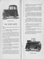
The Austin Seven is particularly suitable lor the woman driver.
It requires little physical ellort to drive and control, and lor that reason
its use enables her to do shopping calls without latigue, visit her lriends,
attend social and other !unctions, or make excursions or trips in any'
direction in any weather.
For the same reasons business men lind it an excellent vehicle, and
commercial travellers and others whose occupation compels Irequent calls
over an extended area have in the little car an embodiment 01 all they
require. Calls can be made in places where trains, trams and 'buses are
inlrequent.
In large establishments, where the instant use 01 a car is 01 vital
importance in cases 01 emergency, such as sudden illness or accident, the
Seven has been installed as a "tender," and in addition to its superiority
over large unwieldy cars lor short runs, has proved a real time and money
saver.
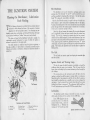
The Au,tin Seveu de lux. Saloou.
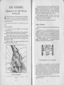
THE AUSTIN SEVEN
T
As 40-42miles per gallon is the average petrol consumption, the cost 01
transit is below the cost 01 lares on any public conveyance.
Its speed, economy, reliability and road-holding qualities have been
admitted beyond dispute.
HE Austin Seven is acknowledged to be the best small car in the
world.
Many thousands of motorists have had their lirst experiences on a
"Seven"; thousands more will lollow them.
It is designed lor, and will carry in comlort, lour adults up to a
weight 01 40 stones and 56 Ibs. 01 luggage.
Having successlully passed through lilteen years 01 severe use and
trial, it has emerged a really success!ul and popular lavourite and its
splendid qualities are internationally recognized.
There are live models made, the Cabriolet, the de luxe Saloon, the
Saloon with lixed head, the Tourer and the Two-Seater.
The closed
models are alike in general lines and general equipment.
Particularly
good leatures are the wide doors and the lour side windowswhich are
~
mechanically raised or lowered.
The large single panel windscreen, which can be opened wide and
secured by an ingenious lever lastening easily reached from the driver's
scat, is another advantage. The Tourer, with its easily operated hood,
and side curtains which open with the doors, provides complete protection
in even the most inclement weather.
'
Both Iront seats are separately adjustable. They tilt lorward and allow
ready access to the rear seats or luggage space.
The Austin Seven has a 4-cylinder, water-cooled engine, synchromesh
gears, and bevel drive. Lubrication is by pump, and cooling is on the
thermo-syphon system assisted by lan.
The complete equipment includes electric starting and lighting
switches, loot operated "dip and switch" lor headlamps, air strangler,
electric horn, speedometer, electric windscreen wiper, automatic return
direction indicators, licence bolder, shock absorbers. spare wheel and
4
"
'I
The Austin Seven T wo.Seater
5
~
7
\
THE NEW
CHASSIS SPECIFICATIONS
'"Engin.
It will Repay YOll to Read these Notes
Carefully.
Th, dim,n,ion, 01 the modd, 'a<y. M.»mum I,ngth 10ft. 7in.
(3,260mm.) Width 4ft.3in.(I,295 mm.); H,ight 5ft.3in. (1,600mm.);
Wh,dh.." 6ft. 9in. (2,057 mm.); Tm,k, fcont, 3ft. 4in. (1.016 mm.)
ma<,3ft. 7in. (1,092 mm.). wound d,a<.n", 6,in., 61in. .nd 7tin.,
mo,ding to mod,1.
Dimensions..
..
I
F
Fom.cylindm, w.t".rool,d, with d,tach,hl, hood.
Bo", 2.2in. (56 mm.); Stook"~3in. (76 mm.) ;
Cuhi, """,ity, 7475 cc.. RAC. mting, 7.8.
B"k, ho",.pow",
17.t 3,800 '.p.m.
Ignition,
Coi!.
Oil ,i"ul.tion,
hy pump: Sump """,ity
Cooling, Th,nno..yphon
with film "di.to,
5 gallon (22.75Ii"",) tank at "".
Start.r
EI,ct,i",!.
Clutch ..
..
Gaarbox
Rear Axl.
Fud ,upply hy A.C. pump.
Fom ,O',d, Io<""d, .nd . 'mm;
Th, top, thi,d .nd ",ond g""
hove ,yn,h,om"h ,ng.g,m,nt. which ,n,u'"
,mouth, noi"I""
wt,in g'" ,h.ng" to ,uit "..,.ing ,O',d,. Fi"t g", i. , Iow on'
to h, used in ,tarting with, lulllo.d, up .n indin,. 0' m,noeuvoing
the m in.n .wkw"d pi.". Th, mtio, of ,ngin"o co.d wheel. ""
top,5.125to I; thi,d, 851 to I; soeond,I353to I,.nd fint, 22.4tiii"
28.8 to 1. B.II hea,ingsthcoughout.Oil",p"ity Iloin".
. . 1.lIo",ing.withdiff",nti.1 .nd 1o<qu,tuh,.
B.1Ih",ings .nd th,.." thcoughout. Fin.1d,ivchy ,h,ft .nd 'pi,,1
hm!.
Oil cop"ity
t pint.
t.dlipti, t"nsvcr" ,p,ing in hont.
Spring...
Qu.rt" dlipti" .t "".
Shock .hso,hm .m fitt,d to f,ont ,nd m".
Frout Axle
.. . Fo,g,d, I "ction.
Brak..
..
On.1Ifomwhool,withindividusl,dj..tm,nt.
Wbeel. ..
..
SO'".I wimd,t"h,hl,. On"p", whooIwithtyre. Ty'" 4.00-17,
.nd 4.75-16 (E.L.P.) Dunlop. V.n" 4.00-18.
Control.
Ligbting
B.II ,h.ng, 'p,od g,a< Im" .nd hook, Im"mountod "n",lIy.
rontcol fo, dip .nd ,witch h"dlight,. Foot .,,01,,",00.
..
Foot
By g",.d,ivcn dyn,,"o, with 6.volt hatt,..,..
Bodywork
Two hu,k,t "", fo, d,iv" .nd p""ng", hoth h,ing hingod to allow
"'y ,nt"n" to the "" ".t. R", "at to ""y two .dul" 0< thm
,hild"n. Ampl, tool ",ommod.tion. Sp", wh,,1 .nd t}T'. On
toming modd, hood, ,ingl, pi", "",n .nd full ,id, ,croon. (tho"
ov" the doo" open with th,m). EI""i, horn, ,p"dom,'", di"ction
indi"to..., dodri, wind"",n wiO'" d,ivin. mino, .nd li"nce
hold,o.
Luggage
Th, m""imump"mi"ihI,lo.d fo, the lugg.g, coni" i, 56Ih..
6
with Austin
cars please read this Handbook
Before running, see the car is
supplied with fuel and water, that the
engine and gearhox have the necessary quantities of oil and that the
battery contains tbe proper amount
of acid.
4 pin".
.nd Ion. Cooling .y,t,m
Cars delivered by road are ready
for running.
There is no oil,
fuel or water in cars crated for overseas and the batteries are empty and
uncharged.
Flexihl, ,ingl,-pI.t" ,p,ingload,d, the pI.t, ""..,.ing the Idction ,ing..
,m'",
you are not familiar
carefully.
Give the new car a general
examination to see that all is in order.
"p"ity 10 pint'. Th", i. . 'p,ing Io.d,d "Ivc in top tank to
p,mnt o",lIow hy ,pl"h.
C,onbhaft h",ing" Fcont,hall; Cout", pl.in; R"" colI"
Fuol Feed
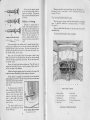
CAR.
j
I
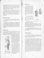
A
A. P,trol Pump Priming Lever.
.
.
Startmg th e E ngme.
B. DrainPlug.
Before attempting to start the engine, make sure that the change speed
lever is in neutral position and the hand brake on.
II the car has been standing for some time, starting should he assisted
by using the hand priming lever on the petrol pump to give the carburetteI
a full supply of petrol.
.Give the engine a few turns with the starting handle to make sure that
the crankshaft is free (pushing the handle in to engage fully with the
starting nut, before turning it). The ignition key is turned to the right
to switch on the ignition and the charging and lighting switch is turned
to "High" or "Low" Charge.
Pull the combined strangler and
throttle control knob on the instrument board to close the carburetter air
inlet, and pttll out the switch to
operate the starter. Be sure to
release the strangler wire after
the engine has started.
Do not
allow the engine to race when first
starting up, as time must he allowed
for the oil to circulate and lubricate
various hearings.
7
.
'}"
\
.
Never leave the ignition switch
on for any lengthy period while the
engine is not running. The warning
lamp on the switch board will remind
you of this.
A
Maximum desirable road speeds during the first 500 miles are:First gear, 7 m.p.h.: second gear, 11 m.p.h.; third gear, 18 m.p.h. and
top gear, 30 m.p.h.
The Starting Handle (Fixed type).
Difficulty in Starting.
."
Str_ler
A-No=.l
,
and Throttle Control.
po.I<ion. B-F.., Idlin"
C-W.=in, Up.
When the engine is running, see that the starting handle is not hanging
down. It should be replaced in a borizontal position at "9 o'clock."
(See page 8).
Difficulty in starting may he
caused either through 'sucking too
much petrol into the cylinders, or too
little. When starting with the throttle
all but closed, a strong suction takes
effect on the slow running jet. If
petrol is passing through the carhuretter the suction can generally be
heard.
There is a catch which will secure it in its proper place there on the
off-sideof the car.
'
The starting handle should be oiled occasionally.
If the engine fails to start quickly and it is thought that the mixture
getting into the cylinders may be too rich, the accelerator pedal should be
depressed half-way to reduce the suction. On firing, the engine will race,
and the throttle should be almost closed. If the engine does not fire, close
the throttle entirely, and try again.
'
After a stop in hot weather, failure of the engine to start is more
likely to be due to a too rich mixture than one too lean, and one should
switch off only after quite closing tbe throttle. Re-start tbe engine with
the throttle closed.
Depress the clutch pedal before switching on. This ;"ill lessen the
starting load and help the starter to turn the engine at higher speed, as
well as save drain on the batteries.
,
If after the foregoing measures have been carried out the engine fails
to start, the reason will probably be faulty ignition or carburation.
If faulty ignition is suspected, first examine the wires and see that the
sparking plugs are connected. Then test the gap of the plug points by means'
of the thick end the gauge provided
in the tool kit. If the points are dirty,
clean them.
a
2
If carburation gives trouble, the
slow running jet may be stopped up
or a main jet cboked. Blow them out
orally or with a tyre pump. Never
attempt to clean them by passing a
wire or other small metal object
through tlrem. This will definitely
injure the jets.
The engine should never be
allowed to run at high speeds during
its first 500 miles.
8
3
4
Au"in
5
0
"Seven" Starting
Oil o""ion.n,
6
9
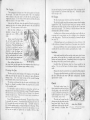
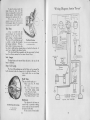
I. Wind"",n Wip",
6. Bmb P,d.!.
2, Ch,ng' Spe,d Lover
3. H,ndbmk, Lover,
8. Horn Button.
In.trumenr.
.0
"SeveD" Controls.
7. Accol,mtor P,d,!.
9. Di"ction
4 Dip ,nd Swilcb Con'm!.
5. Clulcb P,d,!.
H725.
7
Indice'or Swi'ch
10. Vi,",
are lllu.trated ODPage 11.
Handle Position.
" A .nd B.
,.
9
,
--
r
Speedometer.
The figures on the speedometer record up to 100,000 miles or kilo.
metres and they automatically return io zero.
Fuel Gauge.
The flexible shaft of the speedometer drive from the gearbox should be
lubricated by oiling from the speedometer end every 2.000miles. To do
this uncouple the union nut behind the speedometer.
The,luel gauge is electrically operated al)d automatically indicates the
approximate contents 01 the tank when the ignition control is switched on.
When the tank is being relilled, switch 011 and stop the engine and
then switch on again and the needle will record the amount 01 spirit
entering the tank. The capacity is live gallons.
The gauge requires no attention.
The shafting should also be taken down and thoroughly cleaned every
It should be lubricated along its length by applying thin
grease
so
that
when
supply of lubricant. the shaft is replaced in its tubing there will be a good
6.000miles.
Oil Gauge.
The oil gauge indicates that oil is being pumped through the engine
lubrication system and it should be looked at frequently when the engine
is running to ascertain that sullicient pressure is registered.
When the engine is cold high pressure will be recorded, but this is
likely to drop as the oil becomes warmer. If no pressure is registered the
engine should be stopped and the cause 01 the lault ascertained. otherwise
serious damage may be caused.
Flickering 01 the needle may indicate serious shortage 01 oil or a
damaged pipe line.
The gauge may indicate a pressure 0110 Ibs. or more when the engine
is cold or Irom 2 to 10 lbs. when hot. With the engine running at constant
speed the needle should be quite steady.
Wiper,
The windscreen wiper is started by pulling out the handle and swinging
it aside to bring the wiper blade into position on the screen. Then move
the switch to the lelt.
I
On stopping the wiper move the switch to the right and replace the
handle in the top 01 the switch knob so that the blade is held out 01 the
driver's line 01 vision.
.
Ammeter.
I
[
The ammeter indicates the rate 01 discharge 01 the batteries, but does
not indicate current used by the starter motor.
No discharge should be indicated with no electrical equipment in
use or with headlamps on when the car is running at about 20 miles an
hour (30 kms.), or laster.
~
..,
The lighting switch also controls the rate at which the dynamo charges
the battery. "High Charge" should be used in the Winter and when the
car is used very little in the Summer. "Low Charge" is lor Summer use
when the batteries are not used a lot lor lighting, or frequent starting. and
the car is used fairly frequently.
FULL range 01 instruments is provided on all Austin Cars. They
are 01 the highest quality and the lollowing notes explain their uses,
Windscreen
-
When the engine is not'in use the ignition key should be withdrawn
Irom the switchbox. It can be withdrawn only when the ignition is "off."
Fuel and Oil Gauges, Speedometer,
Windscreen Wiper.
'
---
Switch Box.
THE INSTRUMENTS
A
~
Grease should also be smeared round the flange where it rubs the
washer of the key piece wh:ch connects to the speedometer.
T raflic Signals.
"
.
The trallic indicators are con.
trolled lrom the steering wheel.
Normally. after the car has turned a
corner they automatically return. but
when a slight turn has been made it
may be necessary to switch olf.
Panel Lights.
The instruments are illumin.
ated by two lamps controlled by the
same switch. The holders can be
swung aside to facilitate removal of
the bulbs. whichin emergency can
be litted to the side or combinedstop
and tail lamp.
Tb. Im.rumen. PtmeI.
A-S'nn,L".
F-W.rnln, L.mp.
B-oil G.u".
o-I,nl<lon K.,.
C-Amm"...
H-LI,h' Sw""'.
D-D..h L.mp Swl«h. 1- Fu.I G.u,..
E-Sp..dom"",
]-5,..", ConttoL
.
Dip Switch.
The headlamp dipping switch has two lunctions, one to give the
normal driving light and one to dip the near side head.lamp beam and at
the same time switch 011 the ollside headlamp.
If the headlights are on lull, a touch 01 the loot on the switch alters
the lamps to the "dip.and.switch"
position and they remain so until
another touch returns them to the "lull on" position.
Continental headlamps have dual.filament bulbs and are dipped
in the same manner.
Windscreen.
The windscreen is opened by lifting the handle and pushing it lorward.
10
!I
J
.,.
,
\
~
The engine will tb~n belp to retard the speed 01 tbe car. When
using the brake, keep tbe clutcb in, disengaging it at the last moment il
.topping tbe car.
CONTROL OF THE CAR
How
to Change Gear; Some Good
Driving Hints
HE driving
T
seat 01 the Austin Seven is adjustable lor position and
tbis convenience sbould be taken advantage 01 to obtain tbe greatest
comlort.
To engage lirst gear, pusb out the clutcb and move tbe gear lever
into tbe lirst speed position.
.
Sometimes it may bappen tbat wben tbe clutch is let in, tbere
is no apparent drive Irom tbe engine. Tbat is because tbere bas been no
proper engagement 01 tb, gears. Tberelore, pusb out tbe clutcb again,
and it will almost certainly be lound tbat tbe lever can then be moved
so as to give tbe proper gear engagement witbout using any lorce.
Start on'lirst speed, accelerate to about 8 m.p.b., pusb out tbe clutcb,
move tbe lever to neutral, and continue tbe movement 01 the lever steadily
to tbe second speed position and let in tbe clutcb gently.
'
In moving from second to tbird speed, a similar action takes place.
Accelerate to about 18 m.p.b., declutcb, release tbe accelerator, move tbe
lever to neutral and continue tbe movement 01 tbe lever steadily into tbe
tbird speed.
To move from tbird to top, declutch, and move tbe lever steadily
into tbe position desired. It assists tbe cbange Irom top to third, and
tbird to second il tbe accelerator is held down while the change is made.
Skidding.
Skidding is sometimes due to sudden braking on a greasy or loose
surlace and unduly slack tyres contribute to it. If the rear wheels skid,
release the brakes and turn the Iront wbeels towards the direction 01
the skid.
I
I
Synchromesh
.
Change Early.
Always change gear early on a bill. Never allow tbe engine to labour
in any gear and expect it to pick up speed on changing into a lower one
wben the car has nearly stopped. Do not persist in attempting to drive
the car uphill in top gear wben the speed lalls below 18 m.p.h.-cbange
down.
If the car bas been driven back by tbe reverse gear, wait until it is
stationary belore engaging a lorward speed. Do not engage the reverse
gear when the car is travelling lorward. Serious damage to the gears will
be the result.
Keep the loot 011the clutch pedal
except in heavy trallic. Even then
do not allow tbe weight 01 the loot to
be taken by tbe pedal. Tbe slipping
01 the clutcb caused by tbis practice
beats and wears it badly.
When descending a long bill, or
before commencing a steep descent,
engage one 01 the lower gears, and
do not accelerate.
12
Gears.
Tbe gearbox bas lour lorward speeds and a reverse and the second
third and top gears have synchromesh engagement, which ensures silent
positive cbanges.
Cear cbanging may be sligbtly still in a new car until tbe moving
parts bave eased in use. Cbanging sbould not be done burriedly and
no attempt sbould be made to lorce tbe gear lever il engagement is not
made at tbe lirst attempt. Sbould
dilliculty be experienced in engaging a gear wben tbe car is
.tanding, release tbe clutcb lor a
moment and tben try again.
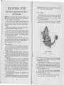
Tbe syncbromesb mecbanism
is governed by a series 01 spring fQtt:',:
loaded balls as illustrated. Tbe
internal cone on tbe inner member
makes contact witb tbe gear
mne to syncbronise tbe speeds 01
botb members belore tbe dog
member, overcoming tbe resistance 01 tbe ball A. moves on to
give positive gear engagement.
Second Speed Synchroni,ing Mecl.anism
A. Spring Ball Re,iotance.
What
I
Not to Do.
Whatever you do, please do not make tbe lollowing mistakes :Do not lorget tbe ignition switcb wben starting up.
Do not make a last run witb tbe radiator mull closed.
Do not be cruel to tbe starter il tbe engine will not lire.
Do not toucb tbe starter switcb wbile a gear is engaged.
Do not leave tbe car in gear and witb tbe bandbrake 011.
Do not coast witb a gear engaged and tbe clutcb beld out.
Do not lill tbe radiator witb cold water wben tbe engine is bot.
Do not leave tbe ignition switcbed on wben tbe car is not running.
On no account run tbe engine in a closed garage.
Tbe exbaust gasses
are bigbly toxic and a very small amount in a restricted atmospbere
The Gear Positi...,.
will produce grave, il not latal results.
13
,
"
"I
REGULAR ATTENTIONS
O
N this and the opposite page is a handy summary of all theattentions
descrihed in this handbook. The attentions under the daily,
weekly, and monthly headings are based on the assumption that the
maximum mileage per week does not exceed 500.
Under more strenuous conditions, for instance, very dusty or very
muddy roads, long distances at high speeds or with heavy loads, It wIll be
advisable to attend to the lubrication of chassis parts more frequently.
After the first few days" use tighten all nuts particularly those on
the engirle cylinder head. These may loosen a little because of the heat
generated, but if they receive this attention both they and the head will
remain !lecure against water leaks or loss of compression.
Waming.-After
the car has been washed, or driven through water.
the hrake linings may be wet. Apply the brakes a number of times for
some distance in order to dry them.
Wet brakes are dangerous.'
Daily
Attentions.
I. Examine water level in radi- .
ator and fill up to within one
inch of the top.
2. Examine oil level in the crankcase and add more oil if
necessary. The dip rod indicates the level of the oil.
Change the oil first at
500 miles, then every 2,000 to
3,000 miles (3,200 to 4,800
km), when the oil reservoir
D.e only recommended Oil..
gauze should be cleaned. The
sump capacity is half a gallon,
3. Fill up' the petrol tank if necessary. Care should be exercised not to overfill the tank, which will contain five gallons.
Weekly
Attentions,
I. With the grease gun chargeFront spring shackle pins (4).
Front wheel swivel pins (2).
Steering cross tube (2).
Steering side tube joints (2).
Rear spring pins (2).
2. Oil the followingClutch release ring.
Foot brake pedal shaft (below steering box),
Brake cross shaft bearings (use a brush).
3, Examine both sets of brakes, and adjust if necessary.
4. Test the tyres for correct pressure and examine them for cuts, flints
and nails.
14
Monthly
Attentions.
I. Examine the oil level in the
gearbox. It should be level
with the filler plug. Capacity,
It pints.
Change at first 1000 and
then every 6,000 miles.
2. Charge the back axle case with
special lubricant, using the
adapter on the grease gun.
Capacity f pint.
.
Change at first 1000 and then
every 6000 miles.
3. Grease all the hubs, as desscribed later.
The Gearbox Oil Filler.
4. Charge the steering box with special lubricant,
5. Oil handbrake gear, pedal gear and joints, engine control joints, and
top of steering column.
6. Examine the battery and see that the connections are tight. (More
frequently in hot weather).
7. Give a charge of the special grease to the nipple on the fan spindle.
8, Give a few drops of oil to the distributor spindle bearing.
9. Grease the front end of the torque tube (behind the front seats).
10. Grease the splined end of the propeller shaft (behind the gear box)
Turn the shaft to expose the nipple.
11. Grease rear brake balance lever,
Occasional
Attentions.
Clean the sparking plugs and check the settings.
Examine all bolts and nuts, such as road spring dips, cylinder head
nuts, wheel nuts, these three especially when the car is new.
Examine other parts, such as steering connections, the radius rod
JUlchorage below the gearbox, and the torque tube socket, neglect of which
might be followed by an expensive repair and inability to use the car for
.a lengthy period.
Occasionally dean the pump and carburetter petrol filters and float
-chamber strainers, and ever 2,000 to 3,000 miles the oil reservoir gauze
(when the engine oil is changed). Also ensure that the oil jets in the
-crankcase are dean.
Flush the radiator with plenty of dean water until it runs through dear.
Clean the ignition distributor, and the contact breaker points (adjust the
latter), the dynamo and starter commutators. Clean the shock absorbers.
.adjust the tappets, and the fan belt, decarbonize the engine and grind-in
the valves. Check the alignment of the front wheels.
15
4
-
..-
,
means of the brace; on some models,
including vans. it is not necessary to
remove them entirely. Pull the wheel
outwards about tin. and turn it a
little to the left so that the large hole
will pass over the nut. The wheel can
now be pulled off the hub.
When replacing these slotted
hubs, make sure that the large holes
in the wheel centre are properly fitted
over their pegs, and tighten the wheel
nuts, each only a few turns at a time,
until they are quite tight and secure.
". .,
Should difficulty b" experienced
upon the first occasion of removing
Do not detach nut.. The wheel
the wheel from the hub. the wheel
will.lide over them.
nuts may be screwed right off. Before
replacing, wipe the outside of the brake drum and inside of the hub
with an oily rag as this will ease removal on future occasions.
WHEELS AND TYRES.
How to use the Jack; Correct Inflation
Pressures
HENit becomes necessary t6 change a wheel hecause of a puncture
or for any other cause. the firstthing to do is to pull the handbrake
"hard on." The spare wheel must be lifted from the rear of the car.
Before it is used test the air pressure and if it is not up to the correct
figure. use the pump to rectify it. The proper pressures are tabulated
on the next page.
It is important~ have the car on
level ground. With the wheel brace
the three nuts of the wheel to be
removed should be slightly slackened.
but only enough for them to unscrew
freely later. The wheel is tb'en
jacked up.
If it is a rear wheel. the jack
should be put in from the'side, between the mudwing and the forward
edge of the. tyre, and should be placed
under the rear spring between the two
clips which embrace the spring leaves.
If a froni wheel is to be attended
to, first slacken the nuts by means of
the wheelbrace. Place the jack under
the front axle neaf but not under the
H' ",.
big nut at the end.
How to use the Jack
The operating bar (which is
on the "Seven."
stored under the rear seat cushion)
fits into the jack by means of a
square tube and 15 secured in that position by a spring loaded ball.
The head of this bar which
engages with the jack must be
pushed well home so that a spring
"".
".'
loaded ball may engage with a slot,
which will prevent the head of the
bar slipping out while the jack is in
use.
W
Care of The Tyres.
""'..
Tyre Size.
4.00-17
4.75-16
4.00-18
4.75-16
~
The jack should be adjusted as
nearly as possible to the required
height by turning the head round by
hand before using the handle to lift
the car.
To detach the wheel from the
hub remove the three nuts by
The Jack, .howing
Extension
16
The key to economical and efficient tyre service is to maintain the
correct pressures and test your tyres at least weekly. Any loss of air
pressure can be made up with very little effort.
A gauge applied to the valve must be used, for it is seldom possible
to detect under-inflation from the tyres' appearance.
Minimum presssures to which tyres should be inflated are :-
(Standard)
(E.L.P.)
(Van)
(Van)
I
I
Rear Tyres.
Front
Tyres.
22
20
22
24
One or two
Passengers.
Fully
Laden.
22
18
-
26
22
26
26
Lbs. per sq. in.
A tyre that loses more than three to four Ibs. per sq. inch in a week
should be regarded as "suspect."
First, make sure that a new valve
"inside" is not required. If the tube is punctured make sure before refitting
that the puncturing object is not still embedded in the cover.
.-1,
It is important that both front tyres be kept at same pressure. If
because of wear or other causes. the steering develops a tendency to wander
or show signs of wobble, the front tyre pressure may temporarily be varied.
17
....
- -
--
--
...
Dirty Tyres.
Oil. paraffin and grease are injurious to rubber. and should be
removed as soon as possible by the
use of a clean cloth and a very little
petrol.
Cuts and Damage.
Damage affecting only the rubber
tread and walls may be plugged with
a good tread cut filling. If this is done.
promptly an extension of the injury T.ght.n.. the and
wheel
nuts alternatdy
..cur.ly.
Wl11 b e prevente d .
Damage of a more serious nature affecting the collon structure should
be entrusted only to an expert tyre repairer or the tyre manu~acturer.
It is essential that the tyre be removed immediately the damage i.
lustained.
.
I
Fitting Hints.
When refitting a tyre attention is called to the following points.
To avoid trapping the tube between the edge of the cover and the
rim, always inflate the tube very slightly before placing it in the cover.
During the final inflation see that the edges of the cover are sea ted
evenly round the edge of the rim. Check this by the moulded line on
the cover. which should be about a quarter of an inch from the rim all
the way round.
Covers are marked with a red spot near the wire edge. This indicates
the lightest part, which should be fitted immediately over the valve.
:::
u
Uneven Wear.
Becausethe front wheelsare .. cambered," or lean outwards, the
'"'
u:> .~
V)
c:
c:P
.~
'"'
'" ....
"
=' ~
~ 0
" ~
..<::
I-<
outer side of the tyre tread wean
more than the inner To minimise
the effect of such wear, turn the tyres,
say every three or four tousand miles,
so that the more worn sides are next
to the car.
.
At the same time, exchange the
near and offside tyres so that the
unequal weight distribution
and
consequent wear caused by road
camber are shared.
~II
Wipe th. inside of th. wheel with
an oily rag.
I
If the front tyres begin to wear
rapidly, have the tracking of the front
wheels checked immediately and, if
necessary, adjusted.
11'
\
18
--
19
-
J
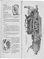
THE PETROL PUMP.
How
P
ETROL is drawn from the tank at the rear'by means 01 an A.C.
petrol pump which advances the Inel in the correct quantity demanded .
by the carburetter, no more and no less.
Service on the petrol pump is available at all Austin Dealers and at all
A.C. service stations, which are prepared with parts and lixtures lor
repairing and adjusting all pumps il any trouble is experienced with the
Inel supply.
Make sure that any dilliculty is not due to causes apart Irom the
pump belore attempting to do anything to the pump.
11 there appears to be lack ollnel at the carburetter. lirst ascertain
if there is any Inel in the tank, and il not. replenish. Make sure that the
pipe and connections between the tank and the pump, and between ,the
pump and the carhuretter, are not leaking. In case 01 broken or damaged
piping replacement should be made.
lt may be that the litter cover of the petrol pump is loose. 11this is
the case, tighten the main nut at the top, lirst ascertaining that the cork
gasket lies lIat in its seat and is not broken or unduly compressed. A
gasket compressed hard may need to be replaced.
~
I
By revolvingshalt (P) the eccentric(0) will jilt rocker arm (Q) which
is pivoted at (S) and which pulls the pull rod (K), together with the
diaphragm (H), downwardagainst the spring pressure U), thus creatinga
vacuum in the pump chamber (C).
Fuellrom the rear tank will enter at (D) into sediment chamber (E)
and through the lilter gauze(A) and suction valve(M) into pump chamber
!
I
I
I
i
E
F
I
G
H
J
Occasionally remove the cover and dean the lilter screen underneath it.
Also remove any sediment Irom the chamher below the lilt er by taking out
the drain plug (F.) Make sure that the libre washer is under the head 01 th.
plug belore replacing.
When re-assembling, take care that the cork gasket is replaced correctly,
under the cover, and that the libre washer is under the head 01 the screw.
11petrol appears to be leaking at the edge 01 the diaphragm tighten
the cover screws alternately and securely, but do not attempt to dismantle
the pump body.
Sometimes there appears to be a leakage 01 luel at the diaphragm
joint. The leakage may actually exist at one 01 the pipe littings, causi~g
the Inel to run down the pump on to the diaphragm lIange.
In hot weather when petrol is likely to evaporate, or when dilliculty
might be expected on cold mornings, it is advisable to lilI the carburetter
by operating the hand priming lever on the pump before attempting to
start the engine. lt will be appreciated that il the engine comes to rest
when the rocker arm is on the high point 01 the eccentric the priming lever
will be inoperative. In the event 01 this the engine should be turned
over one revolution by hand.
The pumping action 01 the diaphragm can be distinctly lelt until
the carburetter bowl is lull.
Alter removal 01 the upper casting on any type 01A.C. Inel pump it is
important that the cover should only be replaced while the pump pull rod
20
-
it works.
11
Clean the Filter.
I.
'"'
is at the top 01its stroke. This is to ensure sullicient lIexing 01the dia.
phragm to allow its normal working movement.
How Fuel is supplied from the Tank to
the Carburetter
,
-~
K
!
,
The A.C. Fuel Pump.
i
I
+
..
F-D"'n
PI",.
L-Prim'n,
lm..
(C). On the return stroke spring pressure U) pushes the diaphragm (H)
upward, lorcing the luel Irom chamber (C) through pressure valve (C)
and opening (B) into the carburetter.
When the carburetter bowl is lilled the lloat in the lloat chamber will
shut 011the inlet needle valve, thus creating a pressure in pump chamber
(G). This pressure will hold diaphragm (H) downward against the spring
pressure U)and it willremain in this positionuntil the carburetter requires
lurther Inel and the needle valve opens.
The rocker arm (Q) is in two pieces, the outer one operating the inner
by making contact at (R) and the movement 01 the eccentric (0) is absorbed
by the "break" when Inel is not required.
Spring (N) is merely lor the purpose 01 keeping the rocker arm (Q)
in constant contact with the eccentric (0) to eliminate noise.
21
;to.
.J
...,..-
.,
A weak mixture may cause difficulty in slow running and this may be
adjusted by turning the regulating screw clockwise to enrich the mixture,
Do not make the mixture too rich or the engine will "hunt," or will tend
to choke when slow running while warm,
ZENITH CARBURETTER
Cleaning and Adjustment for good
Performance
T
Adjustments.
No adjustments should be carried out unless absolutely necessary.
If the engine is positively poor in accelerating when it is running at a
sufficiently warm temperature, and the adjustments described will not
remedy the trouble, it may be desirable to fit a larger compensating jet.
HE carburetter fitted to the Austin Seven is the Zenith "V" type,
embodying the well known principles, of main and compensating
jets.
c
1-
Pelrol from the pump passes through the union, the filter and the
needle seating into the float chamber. As the float rises it will close the
needle on its seating, thus regulating the flow of the petrol.
The float chamber contains the main jet, the compensating jet, the
capacity well, and the slow running jet. Petrol flows through the main
and compensating jets and also rises in the capacity well. From the jets
it flows along two separate channels into a common channel in {he emulsion
block attached to the float chamber. This main channel has its outlet
in a nozzle which projects into the choke tube.
1
Tbe capacity well is in direct communication with the atmosphere,
and the compensating channel in the emulsion block.
.
II
I
i
A
Starting the Engine.
To obtain an easy start from cold the combined throttle and strangler
control on the dashboard should be extended to its third position, and the
engine should be given, by hand, a few turns to free the working parts.
Then pull the self-starter control knob and when the engine is running
release the strangler control to the first notch.
In cold weather it may be, necessary to hold the strangler control
out for a few minutes while the engine warms up, and to run the car for
the first few minutes with the knob in the first notch, As soon as the
engine is warm, however, the control knob should be pushed right in,
otherwise the mixture will be too rich.
I,
!
I:
,I
The V Type Carburetter
A-Pmol
B-Union
C-W"h",
Union
Nm
(without Air.Cleaner).
D-Rm,ning
E-Adjo."n,
F-R"olo"ng
Bol"
Smw
Smw
If the engine does not idle as slowly as desired, turn the screw to the
left to close the throttle slightly,
If there is a lack of power and speed, this may be due to the main jet
being partially choked, or if greater power is desired a larger size rrlliin jet
may be fitted.
Make sure that the strangler flap opens fully, for if this sticks in a
partially closed position it will restrict the speed of the car and increase
petrol consumption.
Do not, however, alter the jets unless you are quite sure that other
parts of the engine, including sparking plugs, ignition and valves are in
order, and that compression is good. There are no moving parts in the
Zenith carburetter, so that nothing can get out of adjustroent when once
set.
22
23
If difficulty in starting the engine is experienced, ascertain that the
strangler flap is closing properly and if necessary adjust the wire.
A choked slow running jet will also cause difficulty. The jet should
be cleaned only by blowing through it, either with a tyre pump or orally.
Trouble can also be experienced if the throttle is not open sufficiently
when the strangler knob ,on the dash is in the first notch. In this case
turn the adjusting screw a little to the right to open the throttle wider. '
ii
"
~~
Standard
Clc"";ing.
The bowl 01 the carburetter should be removed occasionally ./or
cleaning.
Take out the two retaining bolts and the bowl will drop
into the hand. On turning the bowl upside down the float willlall ,out and
reveal the main and compensating jets at the bottom 01 the bowl.
Settings.
Sizes 01 Zenith jets normally run in 5's-the higher the number the
larger the jet.
Settings are likely to be varied to suit certain markets. Standard
settings are :17
Choke
57
Main Jet.
oo
50
Compensating Jet...
60
Slow-running Jet .oo
50
Progression Jet
1.5mm.
Needle Seating
2
Capacity Tube
7
"Leaded" Fuels,
I
~
I
I'
We would recommend this method 01 cleaning lor all valves, whether
they have operated with leaded or ordinary fuels, as it eliminates the
possibility 01 leaving small amounts 01 deposit on the valve seats which
tend to cause damage or prolong the "grinding-in" process.
11
11
3
11
I
li
!
J
ijl
1'[
"'
1
The Carburetter
'I'
2
Bowl.
/
2
4
6
8
l M.in '0<
3 C.",i"
w.ll
5 Emul.lon blo,'
7 Rminin, bol<.
Com,.n.."n,
,0<
Slow.ronn'n, '0<
Non>.
Squm .nd '" 10= '0< «v.
The jets are removed hy litting into them the squared end alone 01
the retaining bolts and using a spanner on the other end. To clean
the jets wash them in petrol, and blow through them to remove obstruction.
Do not me wire.
1
1,.,
j
Air Cleaner.
On export models an oil wetted air cleaner is litted to the carburetter.
At Irequent intervals, say weekly in countries where dust is constantly
experienced, the silencer needs cleaning and re-oiling. It is taken 011
the carburetter by undoing two nuts and it should be swilled in a shallow
pan 01 petrol.
After drying, the metal gauze mesh should be re-oiled with engine oil,
allowing the surplus to drain 011belore relitting the cleaner.
11the air cleaner is neglected it becomes choked with dirt, so that the
cleaning elliciency of the device and its valuable protection against engine
wear are not maintained.
The connection Irom the petrol pump should be dismantled and the
filter thoroughly cleaned in petrol. When reassembling take care that the
washers on either side 01 the union are correctly replaced.
,
111.
Provided that the same reasonahle attention is given to the valves and
other adjustments as with ordinary petrol there will be no trouble when
using "leaded" fuel (petrol containing a small proportion 01 tetraethyl
lead).
'
The appearance 01 the valves when running on "leaded" fuel dillers
Irom that associated with ordinary petrol but this is a well recognised lact
to which no signilicance should be attached.
The deposit from such fuels can be removed by "scrubbing" the
valves and their seats with a still wire brush 01 the type used lor cleaning
liles (a "Iile card"), alter which the valves can he ground-in in the normal
manner.
24
:t
25
~
THE COOLING SYSTEM.
Occasionally flush out the water cooling system by opening the drain
cock at the bottom of the radiator and allowing water to run through until
it comes out clear.
Precautions to take against Freezing and
Overheating
Causes of Overheating.
Overheating may be attributed to onc or more of the following causes :-
T
HE cooling of the engine is maintained by a capacious radiator which
should be filled with rain water if available, up to within about
onc inch of the top of the filler. The capacity of the radiator.
pipes and cylinder jackets is 9-10 pints.
In Winter
an anti-freezing
mixture should be added to the water
in the radiator, because in very
severe weather the water may freeze
and thus damage the cylinder block
or the radiator itself.
Moreover,
when an anti-freeze mixture is used,
there is no need to draw off the water
to prevent damage by frost,
Slack fan belt. The belt can be tightened by turning the fan spindle
in its bracket after loosening the clamping-nut,
Excessive carbon deposit in cylinders.
See "Running Adjustments"
Running with ignition too far retarded.
(See page 31.)
Using oil of poor quality, or lack of oil in the reservoir.
"Engine Lubrication."
l'
The Water Level,
A-M"imum. B-Mioimum.
There is a spring-loaded valve in the top tank of the radiator to prevent
overflow by splash, When emptying the system the filler cap must be
removed or an air lock may prevent complete drainage. This must be
particularly remembered in frosty weather,
Smith's "Bluecol" and Price's "Zero" are suitable.
If such a mixture is not used, care should be taken to see that the water
is drained off completely, for, in case of freezing, it will do harm by lodging
in small spaces, and fracture of the cylinder block may result. In Great
Britain the climate does not very often call for the cooling system to be
drained, but it is well to err on the right side and take due precaution
against damage if frost be threatened.
Partial choking of the oil jets.
Se.
See "Engine Lubrication."
Improper carburetter adjustment, giving a mixture too rich or too
weak. See "The Carburetter."
Failure of water to circulate, because of choked radiator, water
level below the tops of the radiator tubes, or loss of water through
leakage from connections.
Overcooling is almost as bad as overheating,
too cool, use a radiator muff.
If the engine tends to be
Trouble arising from a damaged radiator generally necessitates its
dismantling and despatch to a repair depot.
,.
Freezing.
I;
Kc
11.
I'
In frosty weather freezing may occur first at the bottom of the radiator
or in the lower hose connection. It is sometimes possible to fed ice in the
hOle and break it by squeezing.
Ice in this hose will stop water circulation and may cause boiling.
Before using anti-freeze mixture tighten the cylinder-head nuts to
make sure that none of the mixr.ure gets into the cylinders. The mixture
may do considerable damage if it contaminates the engine oil.
.
Flushing.
!
To prevent the gradual formation of deposits in the cooling system
with consequent impeding of the circulation, the use of hard water should
be avoided. Soft water. rain-water (syphoned from the top of the barrel
where it is clean) or, failing that, water that has been boiled, should be used.
26
Be .ure tbe
road it clear
before opeuU,g
a door.
I \
\ \\
27
-
I
"
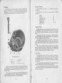
The Distributor,
THE IGNITION SYSTEM
Cleaning the Distributor;
Fault Finding
Lubrication
T
11
HE C,illgnition Equipment is provided with an automati.c advance
mechanism, which relieves the driver of the necessity of constant
adiustment of the hand ignition controL Its advantages are particularly evident when accelerating, and during hill climbing, the danger
of pre-ignition, knocking or "pinking" being very much reduced.
The device is housed in the distributor body and it consists of a
;entrilugally operated mechanism by means of which the ignition is
advanced in proportion to the engine speed.
.
Very little attention is needed to keep the ignition equipment in
first-class condition; we advise that it is inspected occasionally and the
following instructions on lubrication, cleaning and adjustment should be
carried out.
I"
The distributor cover can be removed on springing aside its two
securing clips. The electrodes "A" and "F" and the inside of the cover
are then accessible for cleaning with a dry duster. See that the carbon
brush "B" is clean and moves freely in its holder.
After the first 500 miles running it is usual for the car to be taken to a
service station to have various minor adjustments made to the engine.
As most of the bedding down of the contact breaker heel occurs during this
period the gap between the contacts must be checked and if necessary,
re-set to give a maximum opening of .012 ins.
After this, the gap between the contacts will not require adjustment
until a considerable mileage has been covered, unless the contacts have
burned. The work of re-setting the contacts when this has occurred,
should be left to a skilled mechanic. For the normal adjustment, first turn
the engine by the starting handle until the contacts are seen to be fully open.
. Then, using the ignition screwdriver, slacken the two screws "D" in the
contact plate, and move the plate until the gap is set to the thickness of the
gauge. After making the adjustment care must be taken to tighten the
locking screws.
The CoiL
The coil needs no attention apart from keeping the terminals tight
and the top clean.
I
Ignition
Switch
and
Warning
Lamp.
The key, by means of which the ignition is switched on. should be
withdrawn when the engine is not running. This will ensure that the
battery does not discharge by the current continuing to flow through the
coil windings.
The warning lamp on the instrument panel will light when the
ignition is switched on and the engine is running slowly or is stationary.
Should the bulb of the warning lamp fail this will not affect the ignition,
but it should be replaced as soon as possible so as to act as a safeguard to
the battery. It can be removed from its socket when the small cover plate
holding the red glass is unscrewed. The replacement bulb should be a
2.5 volt 5 wat' screw cap type (Lucas No. C252A) as originally fitted.
11
E
The Contacts,
Lubrication.
1:
Di,tributor
:1
I"
A EI",rod..
B Cubon BMh.
C Con"'"
and Contact Breaker.
D Lo,ki.. Smw.
E Row'n, C,rn
FM.", EI.mod..
28
~\
G Row'n, d",ribu,o, .=
H Cond.no".
J Con"" bmk" plvp,
The distributor spindle bearing is lubricated by means of an oiler
which needs a few drops of thin machine oil every 1,000 miles.
Every 3,000 miles give the cam
and also the pivot "r on which the
contact breaker works, a smear of
Mobilgrease No. 2. Withdraw the
rotating arm "C" from the top of the
~
Ignition Screwdriver
and Gauge
29
,
,
--;>
l
~
spindle by lifting it off and add a few drops of thin oil to the top of .the
spindle. Do not remove the screw exposed to view, as tbere is a clearance
between the screw and the inner face of the spindle tbrough which the oil
passes to luhricate tbe cam bearing. Take care to refit the arm correctly and
to push it on to the shaft as far as possihle.
The moving parts of tbe automatic timing control must he lubricated
with a good grade thin engine oil. To render the control accessible,
remove the distributor moulding and lift off the rotating distributor arm.
Then remove the contact hreaker moulding by withdrawing its two
securing screws. Take care to refit the contact hreaker moulding in its
original position.
.
11
11
B;
I
po'
I
'i.
I
High Tension Leads.
If the high tension cables show signs of perishing or crackmg, they
must be replaced. Use only 7 m.m. rubber covered ignition cable for all
higb tension leads.
To make a connection to tbe distributor or coil terminals. thread
the knurled insulating nut over the lead, bare the end of the cable for about
1 of an inch, thread tbe wire tbrough the hrass washer provided, and bend
back .trand"
When the moulded nut is screwed home, the cable will be
.ecurely clamped, and the nut will support the cable, and prevent vibration
and fracture.
il,
il
il~i
Ii
cH
!"I
'
111
,'"
I:j~
,~~
,."
'
il
'I
"
:,,
30
To test for short circuits in the
Iow tension wiring (the cables from
the switcbboard to the coil, and coil .
to distributor) which would equally
cause irregular running, have the
engine turned while the ignition is
switched on, and watch the ammeter
reading.
It should rise and fall as
the contact breaker points close and
open.
This test will also indicate if
the contact breaker is functioning
correctly.
If the contacts rcmain
open or do not fully close, the readContact Breaker.
ing will not fluctuate.
.
.
A..,mbl",mo"d<O"'O".u<om"',"m'o,.
If the high tension cab Ies fram
the distributor to the plugs are not
.ecurely attached to the distributor, misfiring may occur. Or, if the
rubber insulation on these cables shows signs of perishing and cracking,
there may be leakage of the current giving rise to the same symptom..
Renewing the cables is then the remedy.
If, after verifying the,e points, the trouble remains undiscovered
the equipment should be examined and tested by the nearest service
depot of the makers.
Ignition Faults.
If the engine will not fi<e, or fires erratically, the trouhle may arise
from the carhuretter, or petrol supply.and not the igniton. A partially
cho ked jet, an incorrect petrol level, or air leaks into the induction
system may be tbe faults. Equally, sooted plugs can be suspected, when
dismantling and cleaning them will
remedy the trouble. If the batteries
I
have run down, or the terminals have
worked loose, quite obviously there
will be no spark, and the same results
can be expected if the distributor
electrodes and contact hreaker have
been neglected and are dirty.
The coil can be tested by removing the cable from the centre
socket on the distributor cover, and
holding the end of this cable ahout
c 1 inch from some metal part of the
car while the ignition switch is on and
the engine is turned. A strong and
D
regular spark will result if the coil is
in order. Clean the top of the coil
High T emion Terminal.
A-H.T. C,bl, B-Mould,dT,=io,l
and ensure thatit~ terminals are tight
C-Wuh"
D-C,bl, S,mod.
before making thIS test.
Short Circuits.
Timing
the Ignition.
As it is essential that a spark should occur at the plug points as each
piston reaches the top of its compression stroke, re-timing after dismantling
needs care, but should present no difficulty.
"
.
i
'j
In order to reset the ignition timing remove all sparking plugs excepi
No. I and, using the starting handle, turn the crankshaft until No. I piston
is at top dead centre before a firing stroke. The compression felt at the
handle will denote the correct stroke. Watch the valves, too, as on the
firing stroke both inlet and exhaust valves will be firmly seated. Top dead
centre No. I piston is also marked on the flywheel (1/4), which can be seen
after removing the clutch pit cover (see illustration on page 39), but actually
it is necessary for the ignition to occur somewhat earlier. Therefore turn
the flywheel back about t.in. (12 mm..). Remove the distributor cover,
slacken the screw in the clip of the distributor casing and turn the casing
until the contact breaker points just hegin to open, with the rotating centre
arm pointing to the position of No. I electrode in the distributor cover.
Tbe spark is then correctly timed for No. I cylinder, and of course, for
Nos. 2, 3 and 4.
31
f
"'"
As the distributor cover carries the electrodes for the four cylinders, it
will be realised that it is imperative the rotating arm can pass th'; spark to the
correct sparking plug lead when compression is reached by each piston,
THE SPARKING PLUGS
"
Finally tighten the adjusting screw, refit the distributor cover and test
the car on the road, If the ignition seems too far advanced or retarded it
can be readjusted at the distributor. There is a considerable amount of
latitude for adjustment but only extremely small movement should be
made at one time.
T
HE sparking plugs with which the Seven is now f!tted ~re K.L.G.
"Corundite" type F.50x.
The gaps of these plugs should be maintained between .022-in.
and .025-in. 'If the gap is allowed to become too wide, misfiring at high
speeds is liable to occur, and if too small, bad slow running and idling will
be the results.
If the leads from the distributor to the sparking plugs have been disconnected they must be replaced in ihe firing sequence marked on the
cover, I, 3, 4, 2.
1
I'
To give the maximum strength this type of plug is non-detachable,
but when it is necessary to clean ihem after a few thousand miles' service,
it is a simple matter to take them to a good garage and have them cleaned
on a sandblasting machine. This will have the effect of removing the
unbumt particles which adhere to the internal insulation, as well a. any
soot or oil which may have accumulated during use, and the resultant good
running will amply repay the cost of this quick and simple operation.
"
When putting them
The
the cylinders, make sure that the sparking
When fitting be careful not to knock the top insulation of the plug,
for although it has a strength which is much greater than the ceramic
material usually used for the sparking
plug insulation, a heavy knock might
fracture the insulation and misfiring
will occur.
MAGAZINE
Always remember that cheap oil
and petrol, improper carburetter adjustment and excessive use of the
choke will have the effed of causing
the internal insulation to become foul
and dirty, and also if the high tension
leads are old and the rubber has become hard and cracked, electrical
leakage may occur, with the result that
the plugs will misfire. If the dis.
tributor points are out of adjustment
fouling of the plugs is very liable to
happen.
contains many useful hints designed to help the owner driver to
do those "little attentions" that mean so much toward getting
the best .from his car.
Also there are detailed descriptions of the bigger jobs that can be
tackled at home, explained in" simple language, and properly
illustrated.
E
backinto
plug washer is not defective in any way, and if it looks flat and worn,
fit a new one so that you can be sure of obtaining a gas-tight joint.
There are special features, interesting stories by popular writers,
travel and sports articles, and "motoring miscellanea:'
"
.
~,
.
".
Your Newsagent will deliver the Magazine to you for
4d, a month.
32
If you wish to obtain the maximum efficiency from your engine and
also maintain the good petrol consumption which your car had when it
was new, change your plugs every
10,000 miles, for old plugs are wasteful and give bad and sluggish running.
The .. K.L G." Corundit.
F.50.X. Plug.
33
J
7
m
"1'1
II,
I1'
'I
j,l
jl
"
'I
1
~i
Ij
,1:1\
"I
,I:
1
~I
li!111
1;'
LUBRICATION
Use only the Recommended
Greases
T
Oils and
II
HE correct lubrication of any piece' of machinery is of the utmost
importance, but for ,the modern high-speed automobile engine, which
operates at sustained high temperatures and speeds, it is absolutely
essential that only oils of the highest quality and correct grade be used.
Inferior oils, or unsuitable oils, will almost inevitably cause excessive
wear in an unduly short time.
We cannot over emphasise the
folly of using so-called" cheap"
lubricants.
Modern cars use comparatively
little oil, so that the cost of using a
good lubricant is negligible compared
with the cost of using inferior oil.
Good lubricating oil ensures that you
always get out of your car the best
performance that it can give; it reduces carbon deposit,making frequent
decarbonising unnecessary; it makes
starting easier, thereby avoiding deterioration of the battery; it reduces
engine wear and eliminates avoidable
causes of mechanical breakdown with
Cleaning Ibe Oil Jet..
possible heavy repair bills.
Colloidal
.
.
I
,I,
I,
and consequent wear, to the greatest extent. Nevertheless, it is imperative that the crankcase be drained periodically to remove foreign matter,
and subsequently refilled with fresh clean oil.
Drain the crankcase immediately after a run. when the oil is warm,
and therefore fluid and thoroughly agitated. It will then carry away as
much of the contamination as possible. Never flush the crankcase with
paraffin-'50me will remain in the sump to contaminate the fresh oil, and,
in addition, it may loosen, but not entirely remove, certain deposits which
are best left undisturbed until the engine is overhauled.
.
Rinse gauze filters in petrol and allow to drain before refitting. Do
Dot wipe with fluffy rags,
.
Oil in the gearbox and back axle becomes contaminated with metallic
particles from the gear teeth and these will cause unnecessary wear of the
bearings unless removed. These units should also be drained periodically
and may be flushed with a thin oil. This should be allowed to drain
thorougbly, after which the unit should be filled to the correct level with
fresh oil.
Choice of Lubricants,
Some lubricants are lighter in colour and appear thinner than others.
However, the colour of an oil or its appearance at atmospheric temperatures give no indication as to its efficiency under operating condition.
and temperatures. Therefore, oil should never be judged by colour or
apparent consistency.
The various lubricants which we officially recommend, each of
them having the high grade standard of quality required by our Research
Department, and all of them having proved entirely satisfactory in extended
.ervice, are tabulated on pages 36 and 37. They all have adequate
distribution at garages and filling stations.
Graphite.
Running-in Compound containing colloidal graphite, marketed by
oil companies, is valuable for use during the running-i~ period and is
added to the sump oil in the proportion of one pint to a gallon of any of
the engine oils recommended by the Austin Motor Co.
It is always important, however, to prevent as far as possible oil dilution
by water such'as may be caused by condensation or leaking through the
cylinder head gasket.
Lubricants represent the smallest proportion of your expenditure on
the upkeep of a car, so that it is obviously false economy to use other than
the best.
'
I
I
'[
Impurities.
li
But even the best oil becomes
contaminated with certain impurities
during use. In the engine, these
may be unburnt fuel, carbon, metallic
particles, moisture, etc., and although
the oil itself does not deteriorate the
presence of these impurities must
reduce its efficiency as a lubricant and
in time cause avoidable wear. Oils of
the best quality resist contamination,
34
I
1\
The Anstin "Seven" Engine.
B-oil pump,
C-oil w.".
A-Tho oil Iou.
35
I
....
.
D-To p""u"
'"u",
,
{I
.
~I
~
1
4.ustin
"Seven"
Lubrication
..
. Chart
I
E
I
I:
1I
I
Ilf
HI
I'
n
E
X-BRAKE
A.
R
C.
D.
Crank"",. R,pl,ni,h to full mark on dip."irk daily.
Gearbox. R,pl,nish monthly.
RearAxl, and Ste"ing Box. R,pl,nish monthly~S",rial
Qutrh mthdrawal sl,m. Oil weekly.
Engine:
Summer ..
\1
Oil. ,
St",ing Cro" Tube (2). Steering Side Tube (2). Swivd
Axl" (2). Spring Bu,h" (6. Gr"", weekly.
G. Torque Tube. front end. PI0",11" Shaft, ,plin,d end. R",
B"k, Balan" Lev". Gea" monthly.
H. Top of S""ing Column. @ilmonthly.
I!
il
l
I:
::[
,~
'\
"Prires"
"Duckham',"
"V.cnnm"
Mobiloil
A
Mobiloil
A
Doubl,
Sh,1I
Doubl,
Sh,1I
Pa',nt
E"olube
40
wtrol XL
Patent
E"olub,
Ca,trol XL
30
Motorin,
C
Motorin,
M
Adroidi,ed
NP.\
Adroidi,ed
NPXX
Gear Box ..
Tripl,
Sh,1I
Patent
E,rolub,
40
wtrol XXL
Motorin,
C
Adroidi"d
NP3
Mobiloil
RR
Wheel Huhs
aod
Grease Gnn
'h,1I R.R Ca"rol"",
G"a"
Heavy
Bdmolin'
C
H.B.R
Mobilg"""
No. 4
Wint"
..
'Rear Axle aod E.P. Spi"x Ca,trol
Steeriog Box
Heavy Hi.Pr'"
Gear Oil
E"o
Grea"
Motorin'
E"oleum
E.P.
Exp" 110
36
j, Huhs. Gr"", monthly.
K. Distributor. Oil ,paringlyeverylOoomil".
L. Fan Bearing. Gr"", monthly.
E.
RecommendM
"Shell" "Wakefield" "Essolnbe"
H.7. J4.A.
AD)USTERS.
G"a"
Tripl,
XSp""
Lubricants.
Distrihntor,
00 Cups aod
ooeao
Upper
Cylinder
Lnhrir.tion
Spriogs
Rnsted
Parts or
Squeakx
Mnbiloil
E.P.
M. Brak, and Throttl, Control joints, Starting Handl, and B"ke
Pedal Sbaft. Oil weekly.
"Prires"
"Duckham's"
"V.cnnm"
Hand.iil
Heavy
Adroidi,ed
N.P.O.
Gargoyl,
Vdorit,
D
P,tmix
Motorin,
V.c.L.
Durkham',
Adroid,
Gargoyl,
VCL
E,rolube
30
Price's
P,n,t",ing
Oil
Durkham',
Ea,ing
Oil
Voro
P,n,trating
Oil
"Shell" I"Wakefield"I"Essolube"
E,rolub,
Sh,1I
Oili,
30
Singl,
i
V.CL
Shdl'
Sh,1I
Wak,fidd
Ca,trollo
I
I
Wak,fi,ld
Ca",ol
Penetrating Penetrating
Oil
I
Oil
*Also jaba Oil.
,
37
J
,
'JI
The Engine.
See that the drainplug is screwed up tight, then. fill the crankcase with oil
to the maximum level as shown on the dipper rod. About half a gallon
will be enough to fill.
'
.
The recommended lubricants are of the correct quality and viscosity
for our units. The matter of the proper grade of oil is very important
both in relation to the pump used to circulate the oil. and the gauge to
register the pressure; if a very thick oil were used on a cold day. the pump
might be strained or the gauge broken.
.
After the first 500 miles. drain the original oil from the reservoir by
removing the plug in the bottom. while the engine is hot, and refill with
new oil. The sump capacity is half a gallon.
After the first re.filling it is
advisable to change the oil in the
engine after every 2.000 to, 3.000
miles.
Oil
.
1<
"
Always inspect the level of the
oil, and add enough to fill to the
correct level before starting on a
long journey. The oil level should not
be allowed to go below 1 inch on
the bottom of the dipper rod. It is
advisable to wipe the dipper rod
before taking the reading of the level.
and the reading should only be taken
when the engine is not running and
the car is on the level ground.
:1
~.
After refilling with fresh oil to
Tbe Oil Dip Rod.
the correct level. run the engine for a few moments to check that the OIl
is c;'culating and that the oil pressure gauge reading is correct.
Cleaning
1117",
'<.
W
,\
the Jets.
The front and rear main bearings of the engine are of the ball and
roller type, and the oily vapour in the crankcase is quite sufficient to
lubricate these. The centre main bearing and the camshaft bearings
are lubricated under pressure from the pump.
The pistons are lubricated by the oily vapour. and lubrication of the
big.ends is effected by catching oil from the pump.fed jets in pockets
on the crankshaft webs.
It is advisable to make sure these jets are always clear. and to do so
the plugs over the jets (A) (see illustration on page 35) should be occasion.
ally removed and a piece of stiff wire. not above 18 gauge (I, in. diameter)
inserted through the jets. This prevents foreign matter accumulating in
the oil jets and choking them.
'I
,,'
I
Every 3.000 miles remove the oil reservoir. The gauze oil tray will then
be accessible for removal. Scrupulously clean the gauze and remove all
dirt from inside the reservoir and replace them.
Carefully remake the
joint with the packing washer, covering both sides of it with gre!"e. When
tightening up the nuts holding the oil reservoir to the crankcase, do not
pull up one nut tight, but tighten each nut equally, a little at a time.
38
j
Gauge.
The oil pressure gauge records in pounds per square inch.
The dial will probably record the maximum pressure when the engine
i. started from" cold" but as the engine warms up in running, so the oil
will become more fluid and the pressure may fall quite Iow-it may even
record only one pound. This. however, is sufficient because if the oil i.
circulating that is all that is necessary.
A sudden rise to a higher pressure reading than normal, while the car
is running with .a warm engine, may be an indication of an obstruction
in the oiling system. This fault may be remedied by cleaning the oil jets
(see page 35).
.
A flickering finger may be an indication 01 a serious deficiency of oil
in the crankcase, a damaged oil pipe line or a loose gauge' pipe connection
Any unusual difference from normal registration should be quickly
noticed and the cause of the variations ascertained and set right.
Gearbox.
In the angle formed by the floor and the raised portion which is over
the gearbox, on the near side, is a movable cover secured by a screw.
Unscrew and remove this cover. Immediately below it is the plug of the
hole through which oil is poured into the gearbox.
Carefully follow the lubrication chart for oil most suitable for the
gearbox. Do not use thick gear oil, otherwise seizure of bearings may
result.
Maintain the oil at the correct level, i.e., bottom of the filler plug hole.
The gearbox should be drained. and refilled to the correct level after
the first. 1,000 miles and every 6,000 miles subsequently. Quantity
approximately It pints.
Clutch.
The clutch surfaces being of a
fabric material must be kept Ire~ from
oil and grease, or the clutch will fail
to grip. Lubricate the operating ring
lightly through the oiler, as shown
on the sketch, once a week.
The oiler can be seen from the
driving seat when the rubber mat has
been turned back. Press the clutch
pedal down a little and the oiler will
move forwards to facilitate lubri.
cation.
Austin Seven Flywheel
A-FI,wh,d.
B-Fl,whool Timing Muk
C-Clu"h Rin, Lubri,",o,.
39
i1
"'
)
-
-
..,
Steering Gear..
To obtain easy steering it is important to give regular attention as
regards lubrication. The oil plug
is on the top of the steering box and
if a charge of E. P. lubricant is
given once a month it is sufficient to
lubricate the bearings of the worm and
sector and also lubricate the worm.
If too much is injected at this
point. it will get up the column and
exude round the steering wheel. The
bearing at the top of the column, just
under the steering wheel, can be
given a little oil from the oil-can.
Nipples on each swivel axle, at
'
each end of the steering side tube and
Oilmgteh R ear A...1
.
at each en d 0f t he steenng cross
tube, should be given a charge of grease once a week.
It is advisable to jack up the front axle for this job.
Rear
Axle.
Brake Gear.
All joints, etc., should be oiled once, a week, including a hole
on the brake pedal shaft below the steering box. Use a brush dipped in
oil to lubricate the cross shaft bearings.
The front wheel brake cam spindle is lubricated from the swivel pin.
Front
I
The swivel pins are lubricated with the grease gun and should receive
attention once a week.
Radius Rod Anchorage.
729.'
I
i'
Oil should be applied occasionally to the cups and ball flange fanning
the radius rod anchorage on the front cross member, just 'below the rear
of the gearbox.
Fan.
The fan bearing requires a charge of grease once a month through the
nipple on the fan bracket.
,
For the rear axle, attention every 1,000 miles should be sufficient.
A special oil is used and is injected into the axle casing from the nearside,
using the special adapter. First remove the plug, then place the end of
tbe adapter into the oiling hole. and grasping the barrel of the grease gun,
push. The plug also serves as an oil level indicator.
Therefore do not replace the plug at once, but give time for the
superfluous oil to run out, if too much lubricant has been injected. Thi.
i. most important, because if the back axle is overfilled the lubricant
may leak through on to the brakes and render them ineffective.
Drain the rear axle every 6,000 miles. and replenish to the correct level.
It is most important to use only the correct grade of rear axle lubricant,
Different brands of extreme pressure oils will not mix and it is essential
to use the same brand when "topping up." If the same brand is not
available the axle should be emptied and refilled.
Torque
Axle.
Tube.
There is a raised casing in the centre of the floor. Behind the front
seats, on this casing, is a detachable panel, which is removed to give access to
the greasing point on the front end of the torque tube, which requires
grease monthly. The hole is plugged with a short bolt, which must first
be removed with a spanner (actually the wheel-brace will remove the bolt
very effectively). Use the' grease gun adapter.
Propeller
Shaft.
The front, splined end of the propeller shaft is lubricated through a
Oein the floortunnel on the near side and just behind the gearbox.
A small leather flap covers the hole. Grease should be applied
through the grease nipple monthly. It may be necessaryto movethe car
in order to turn the shaft and exposethe nipple.
40
Road Springs.
The rear ends of the rear road springs where they are attached to the
axle are provided with greasing nipples. and should be given a charge
once a week if the car is continually used. To ensure the best results it is
essential that the road springs should
be Jubricated.
A penetrating oil
should be used. It can be sprayed
from the container or applied with a
brush.
If the rear wheels are removed the springs are fully accessible.
The front spring should be
similarly lubricated, and the shackles
greased at the four nipples provided.
The Hu~s.
Both front and rear hubs require
occasional greasing
Remove the rood wheel. Turn the
hub :mtil the plug "X" is at the top.
Screw out the plug, apply the
adapter of the grease gun and inject
about a quarter of a gun full.
It IS important that the hubs
are not given too much grease otherwise it will penetrate to the brakes
to render them ineffective.
Oncea month, orevery 2,OOOmiles
is often enough for this attention.
.
Austin Seven Rear Huh.
A-Exp.nd" Con, F-Bnk, Drum.
B-B..nns N".
G-Adj"",Con,.
C-Axl, Sh.f< N". H-Adj"", Hood.
D-Axl, Ko,.
K-F", W..h".
E-S" 'mw.
X-o"", PI",
41
~
,I
J
-
,
/
Speedometer
11.
I
II
The shafting should also be taken
down and thoroughly cleaned about
every 6,000 miles. It should then be
I
lubricated along its whole length
~I
II'
'
I1
I
ii
THE GREASE GUN.
Drive.
The flexible shaft of the speedometer drive from the gearbox should
be lubricated by oiling from the
speedometer end every 2.000miles.
To do this uncouple the union nut
behind the speedometer.
Special Adapter for Injecting Rear Axle
and Steering Box Lubricant.
.
Cable,
.by applying thin grease. so that when the shaft is replaced in its tubing
there will be a good supply of lubricant.
Grease should also be smeared round the flange where it rubs the
washer of the key piece which connects to the speedometer.
Upper Cylinder Lubrication.
Upper cylinder lubrication has been found to be beneficial to the
running of the engine.
'
Mixing it with the fuel when refilling the tank is quite satisfactory.
Follow the instructions given with the various brands.
I
!',
,;11
Grease
T
Removingand Oilingthe Speedometer
"
HE type of grease gun supplied in the tool kit of all Austin cars
incorporates features by which the chassis lubrication of the car is
greatly simplified.
Once the gun has been charged all that is necessary is to push the ram
against the nipple until the contents are exhausted. Three or four strokes
for each nipple are sufficient.
The ram is used for forcing grease through nipples, and the adapter
for lubricating the back axle and steering box with special oil. For this
operation remove the end cap from the barrel and charge the gun to about
three-quarters of its capacity. Put the cap of the adapter on the open end
and after removing the plug from the back axle, place the end of the adapter
into the greasing hole, and, grasping the barrel, push. This will inject
a large quantity of lubricant quickly.
When charging the gun with grease it should be filled with lubricant
to about three-quarters of its capacity.
Nipples.
If a grease nipple becomes choked, unscrew and remove it. It can
usually be cleared by soaking it in paraffin or petrol. and syringing either
of these through it. but should it be found impossible to clear it, fit a new
nipple in its place.
Always wipe each nipple with rag and carefully remove dirt and old
grease before applying the gun.
'I
'"
!
'AN
I!
"I
,I
1:
INVITATION
A USTIN
.t"\
OWNERS
and others interested are
invited to visit Britain's largest self-contained motor
works and see how Austin Cars are made.
~
The normal tour of the Works occupies two hours. and
appointments should be made whenever possible.
Tours commence daily, except Saturdays and Sundays
at IQ a.m and 2 p.Q1.
Visitors should ask the Commissionaire for the Reception
Department. or make arrangoments through a local Austin
Dealer.
'!
{,
~
42
43
~
-
"I
ELECTRICAL
,
Cleaning
III
I
Commutators
and Brushes ;
Battery Attention
T
HE lighting and starting units on the Austin Seven car are arranged
for wiring on the single wire system, one path of the current being
provided by the frame instead of a second wire. It is' therelore
essential that all units are in good metallic contact with the frame.
.11
"
I'
EQUIPMENT
1
1
I
1I
I'I
I:
",11
Should difficulties arise that cannot be understood or remedied
from the information given below, application should at once be made
to the Austin Service Department or the nearest service depot of the
makers of the equipment.
Dynamo.
The dynamo is a simple self-regulating third brush machine. The
only parts calling for any attention are the commutator and brushes,
which are readily accessible when the cover is removed.
The commutator surface must be kept clean and free from oil or
brush 'dust. It may be cleaned with ordinary soft rag, but if it has been
neglected use fine glass paper.
Blow away any carbon dust, see that the
carbon brushes are wearing evenly and that they are free to slide in their
holders.
The dynamo bearings are packed with lubricant belore leaving the
works. When the car is overhauled, it is advisable to have the machine
dismantled and the bearings repacked with lubricant. This work is prelerably carried out at a Lucas Service Depot.
,,
'1111
Dynamo
~,
Starting Motor.
The commutator and brush gear are accessible on removing the sheet
metal band cover. The unit requires very little attention beyond keeping
the commutator clean and free from oil, brush dust, etc., as in the case of the
dynamo. Remember that although the starter will turn the engine over,
however stiff, It is advisable when cold, to crank the engine over by
hand for two or three revolutions ~s this will considerably diminish the
load for starting.
If the starter pinion jams in mesh with the flywheel ring when operating the starting motor switch, usually it can be released by putting the
gear lever into top gear, and moving the car bodily backward and forward.
If this plan is ineffectual the starter will have to be dismantled.
Never use the starting motor to propel the car, as it throws too severe
. strain on the battery and the motor.
If the engine does not start at the first attempt, do not press the
.tarter switch until the engine has come to rest. If this precaution is not
adopted, the starter ring teeth on the flywheel, or the starter pinion teeth,
may be damaged.
Switch
Board
A key is provided by means of which the ignition switch is moved
so that the engine can be started. When the slot into which the key fits
is in a vertical position, the key may be withdrawn. The igmtion is then
cut off. To switch on the ignition,
A
insert the key and turn to the right
until the slot is in a horizontal line.
The key cannot be withdrawn while
the ignition is switched on; it must
first be turned off and the slot be in
a vertical position.
The lighting and charging switch
Field Fuse.
A fuse is provided in the dynamo field circuit to protect the machine
in the event of anything being wrong in the charging circuit, e.g., a loose
or broken battery connection. The fuse is of the cartridge type and is
housed with the half charge resistance in the cut-out and fuse unit on the
engine side of the dash (see page 47).
If the dynamo fails to charge the battery at any time (indicated by a
discharge reading being given on the ammeter during daytime running)
inspect the fuse and if it has blown replace it with the spare fuse provided,
after inspecting the charging circuit wiring for loose or broken connections
and remedying. This fuse must not be replaced while the engine is
running. If the new fuse blows after starting up, the tause of the trouble
must be found, and we advise that the equipment is examined at one of
the Service Depots.
,[,',ll
,I
Never fit any fuse other than the Lucas standard fuse as originally
fitted. The size of the fuse is marked on a coloured paper slip which can
be seen inside the fuse.
44
"
positions are:"
Low Charge. -Dynamo
about
half its normal
JII~"
..
'11Jl/IIIJ
gIVIng -r1
output,
V
"High Charge."- Dynamo giv- B
ing its full daytime output.
"Side."-Side
lamp on.
Lamps and tail
"Head."-Head
Lamps, side
lamps, and tail lamp on.
c
The Dynamo
A-Bw,h S.dng,
B-Bw.h.
C--commu","',
The dynamo automatically gives its full output when the headlamps
are switched on.
45
,
..,.
Dipper
I1
'I
Switch.
The dipper switch has two functions-one to give the normal driving
light, and one to dip the near side head lamp beam and at the same time
switch off the offside headlamp.
If the headlights are on full, a touch of the foot on the switch
alters the lights to the "dip and switch" position, and they remain so
until another touch returns them to the "full on" position.
Ammeter.
II
i'lil
The second fuse protects the dynamo. and is connected in the dynamo
field circuit. The indication of a blown dynamo fuse is that the dynamo
will fail to charge, no charge reading being given on the ammeter under
normal daytime running conditions.
Spare fuses are provided for use in cases of emergency. Before
fitting a replacement fuse, examine the wiring of the equipment the fuse
protects for loose connections or short circuits, and remedy. If the new
fuse blows and the cause cannot be found, we advise the owner to have
his equipment examined at a Lucas Service Depot.
The centre zero ammeter indicates the rate at which the battery is
being charged or discharged under all conditions. For instance suppose
2 amperes are consumed when the side and tail lamps are switched on,
and that the ignition coil takes 2 amperes, then if the dynamo is generating
7 amperes the meter will show 3 amperes on the charge side of the scale.
This is the current in e~cess of the lamp and ignition load that is available
for charging purposes.
A
D
The ammeter gives an indication that the system is' functioning
satisfactorily. .For example if no reading is given on the charge side of
the scale when the ignition and charging switch is in tbe "High Charge"
position and the car is running at say 20 m.p.h. with no lights on, then
a fault in the dynamo charging circuit is indicated.
F
To determine the output of the dynamo, switch off all the lights
and add the amount of current used for ignition (about 2 amperes at
normal speeds) to the reading given on the ammeter.
The amount of current used for ignition may be somewhat higher
than the above figure when starting. The ammeter does not indicate
the amount of current used by the starter.
Cut-ont
Unit.
The cut-o;'t is mounted together with two fuses as one unit, which
also forms a junction box and incorporates the half-charge resistance for
the dynamo. The cut-out automatically closes the charging circuit as
soon as the dynamo voltage rises sufficien,ly above that of the battery.
When the dynamo voltage falls below that of the battery the reverse action
take, place, the cut-out opens ami thereby prevents the battery from
discharging itself through the dynamo.
Take care not to close the cut-out contacts when removing or replacing
the cover, as this may cause damage to the equipment.
The two fuses fitted are of the cartridge type. One of them is connected in the accessories circuits, and will blow in the event of a short
circuit in the wiring of the electric horn, windscreen wiper, and other
units connected to the "AUX" terminal, the indication that the fuse has
blown being the failure of these units.
46
tl
Cut Out and Fus. Unit.
A-Co< 00< "mow".
6-Coo,"",.
C-A"",o,'"
fm,.
o-o,o,mo fioldto".
R-A"",o<'" mm",!.
F-S,mfo'...
Never fit any fuse other than the standard Lucas fuse as originally
fitted. The size of the fuse is marked on a coloured paper slip inside the
fuse.
Battery.
The battery is the reservoir of the energy generated by the dynamo
.
and upon its satisfactory functioning depends the starting and running of
the car
The amount of attention needed is small and need take only a few
minutes. Follow the directions given here and your battery will last
longer and give belter service.
When examining the battery, do not hold naked lights near the venl
plugs as lhere is a possible danger of igniting the gas coming from the
plates.
47
,
"
..,..
I
The Electrolyte.
Once a month unscrew the filler
caps and pour a small quantity 01
di.tilled water into each 01 the cells
to bring the acid just level with the
tops of the separators.
i
,I
I
!I.
III
H
1
il
1
B'
The Battery
A-Top of S,p.,,<on.
B-Top
of PI""
C-Add Lml.
Distilled water can be obtained
Irom any chemist and most garages.
Do not use tap water, as it contains
impurities detrimental to the battery.
If any acid is accidentally spilled
from the battery, it must be replaced
by a dilute sulphuric acid solution
of the same specific gravity as the
acid in the cell.
This is measured
by a hydromeier.
Keeptheterminals
clean and tight and well smeared with vaseline.
A liberal smearing 01 vaseline protects the terminals Irom the corrosive
action 01 the acid, which, if allowed to continue. unchecked, mgy eventually
result in a breakage 01 the battery wiring.
Keep the outside 01 the battery clean and dry, particularly the tops 01
the cells. Dirl and moisture will form a conductor of electricity, and il
such a path is allowed to lorm between the positive and negative t"mic,als
01 the battery there will be a leakage 01 current which will ca"'e the battery
to run down. Give the cell tops a regular wipe over and you will avoid this.
Once a month, make a point 01 examining the health of the battery by
taking hydrometer readings. The operation is quite simple and need not
take long. There is r.o better way of ascertaining the state of charge of the
battery .
The specific gravity readings
are :-1.285 to 1.300, battery lully
charged: 1.210. about hall discharged
and 1.150 cOJ1lpletely discharged.
These figures are given assuming the
temperature 01 the solution IS about
60 degrees F.
Do not leave the battery in a.
discharged condition for any length
of time. If the car is to be out 01 use
lor any length of time, see that the
battery is fully charged and about
every lortnight give it a short reIreshing charge to prevent any tendency 01 permanent sulphation of the
plates. In no circumstances must the
electrolyte be removed Irom the
battery and the plates allowed to dry,
as certain changes take. place which
Test
the specif~cgravity
of hattery
e!ectroh'e
wJlh an hydrometer..
result "n Ioss 0 I capaCI ty.
48
('I
When the battery arrives e~pty (as in the case 01 cars sent abroad)
the lirst thing to do is to fill and charge it.
This means that a fluid is prepared composed of one part (by volume)
of pure brimstone concentrated sulphuric acid with three parts (by volume)
01 distilled water. Mix these in a glazed earthenware vessel. Great care
must be taken in this operation. Add the acid in very small quantitites,
almost drop by drop, and stir with a glass rod.
Never add the water to the acid. This is highly dangerous and a
serious explosion may result.
This mixing generates heat, and it is importgnt that the electrolyte
(as the mixture is called) should not be used in the battery before it has
been allowed to cool. Pour the electrolyte into the cells 01 the battery
by means of a lead, glass or celluloid funnel, until it completely fills the
cells to the top 01 the vent hole. Allow the battery to remain in this
condition for 10 minutes or so, then put in more acid solution so that each
cell is again lilled to the same point with electrolyte. The electrolyte will
have a specilic gravity 011.285 when lully charged. Batteries should stand
at least twelve hours alter their first filling belore charging is begun.
01 course if it is de:;ired. the battery can be filled at almost any Service
Station.
Direction
Indicators.
Every two or three months raise the uTrafficatorU arm and, by means
01 a brush or other suitable article, apply a drop 01 thin machine oil, such
as sewing machine or typewriter oil, to the hinge between the arm and
the operating mechanism.
To replace a bulb, switch the
uT rafficator" on and then, supporting the arm, move the switch to the
off position.
Withdraw the screw on the
underside of the arm and slide 011
the metal plate. The burnt-out bulb
can then be replaced. To replace the
metalplate, slide it on in an upwards
direction so that the side plates
engage with the slots on the underside of the spindle bearing. Finally,
secure the plate by means of its
lixing screw.
Bulbs fitted:
\
~
c?
<:
""'
The Direction Indicator.
Lucas No. 255, 6 volt, 3-watt festoon type.
If the direction indicators or electric petrol gauge lail to function,
examine the fuse protecting them. This is litted on the dash near the
cut-out. If it has blown, inspect the wiring for a short circuit.
49
..j
,
"'f'!
{I'
THE LAMPS
If the new luse blows, the cause 01 the trouble must be found, and
we advise that the equipment be examined by a Lucas Service Depot.
Fuel Gauge.
The electric fuel gauge is automatic and registers the contents 01
the'luel tank. It is active only when the ignition is switched on. Consequently when the tank is being replenished, lirst switch off the ignition
to stop the engine, then switch on again and the needle on the dial will
record the amount 01 spirit which is poured 'into the tank.
The gauge is very unlikely to lail, but in this eventuality, Messrs.
S. Smith and Sons (MA), Cricklewood Works, London, N.W.2. (the
makers) or their depots will give prompt service.
Electric Horn.
The horns, belore being passed out 01 the works, are adjusted to
give their best perlormance and will give a long period 01 service without
any attention. No subsequent adjustment is required.
If the horn becomes uncertain
in its action, giving only a choking
sound, or does not vibrate, it does
not lollow that the horn has broken
down.
First ascertain thal the
trouble is not due to some outside
source, e.g., a discharged battery,
a loose connection or short circuit
in the wiring 01 the horn, or a blown
luse.
It is also possible that the
perlormance 01 a horn may be upset
by the horn becoming loose on its
I
!'
Test the horn lead with a hulh to mounting.
ascertaiu if the wiriug is faulty.
This can be .ascertained by re.
moving the horn lrom its mounting,
holding it in the hand and pressing the push. If the note is still un..tislactory. do not attempt to dismantle the horn, but return it to the
makers .
Electric Windscreen Wiper.
11
To start, pull out the curved handle and swing it aside so as to move
the cleaning arm into position on the screen.
Then move the control
switch to the Ielt. To stop the wiper, move the switch to the right. Then
pull out the curved handle to disengage the wiper Irom the gears, and turn
it into the top 01 the switch knob. This locks the arm out 01 the line 01
vision 01 the driver and also ensures that the wiper is switched off.
The wiper requires no attention; all moving parts are packed with
grease during assembly and no lubrication is required.
When cleaning the windscree~, the wiper arm can he easily lifted Irom
the screen, but care must be taken that it is not lorced Irom side to side.
50
~
Dip and Switch Mechanism and How to
Replace Fuses
T
HE head lamps are provided with an electrically operated anti..!azzle
device for operation by the foot switch. When the switch is moved.
to the "dip" position, the near-side headlamp beam is dipped and
turned to the nearside of the road, while at the same time, the offside headlamp is switched off, thus causing no discomfort to drivers of approaching
traffic.
The dipping of the head-lamp
beam is effected by a movement of
the reflector. This is made in two
parts; the centre portion is pivotted
in a fixed rim which is in turn secured
to the body. Movement of the reflector is controlled by means of a
A
solenoid and plunger which, when
the current is switched on, tilts the
reflector to give the dipped beam.
To remove th~ lamp front,
slacken the fixing screw at the hottom
of the lamp and swing it aside from
mpping Headlamp Reflector.
the slot. The front can. then he wIth-
.d
" mm,
.
I
I
A. M
"'
,h . m.no.
pun,..
drawn. When replacmg, press the
o,l;n, ,h. pivouB.of ,h. d'pp'n, ..awo..
front on to the lamp hody, locating
fu.. ,"oubl.".n b. ov",om..
the top of the rim first.
Finally
swing the screw into the slot and tighten it to lock the Iront into DOsition.
To remove the nearside rellector, withdraw the lixing screw at the
back of the lamp. The rellector can then be withdrawn by dislocating
the tongues 01 the two lixing hrackets rivetted to the rellector rim from
the slots in the lamp body. The offside rellector can be removed by
turning back the ends 01 the cork washer and removing the two screws at
the top 01 the lamp.
To replace a bulb in this lamp,
it is lirst necessary to remove the
bulb holder Irom the rear 01 the
rellector by springing back the two
securing spring clips.
To obtain the best results lrom
the lamps it is essential that they are
';{i~~~;,:;:~:
in good alignment and that the bulbs
(../'"
are locussed correctly.
Alternative positions are provided lor the head lamp bulb in ihl
holder. Each position to be tried
How the ;..trument
Lamp
lor the best projection 01 light.
swivels for hulh replacement.
51
.
~
""!"
If
To align' the lamps, slacken the
single fixing nut, then move the
lamp on its adjustable mounting to the
desired position, finally locking the
adjustment by tightening the nut.
If the lamps go dim for no
apparent reason and the batteries are
fully charged, tighten the mounting
nuts to ensure a good "earth."
Wiring
Diagram
Austin
"Seven"
."
,~" Cl"". ..,~,.
~
""""w",,
The Fuse.
A fuse is provided with the
electrical dipper unit to protect the
equipment in the event of the reflector failing to function properly.
Headlamp Fo"",.in..
The fuse is of the cartridge type, and
is carried in spring clips alongside
Th, bolb h.. ,hm 'o,o"'n. po,"'on.
the dipping mechanism.' If the reon oh. b"on.. hold...
flector fails to function, remove the
fuse from its holder and see whether there is a break in the fuse wire. A
spare fuse is clipped to the reflector bracket.
If the fuse should blow repeatedly, and the cause cannot be found,
have the reflector examined at the nearest Service Depot.
III
11
,wo,,'""'
",,
"'"
M'no"
"0"00","
'A~"
"
~,
} t
H21
o"
hs-a
H>
Cf~
.
.
I-""""",
mcow.
---'"""'
W'"o'"'"
.mow .
'°,"
T
"'0", "le ,,",.
Side Lamps.
The lamp front can be removed when the screw. at the top of the
lamp i. slackened.
11,
I
i
i
Stop-Tail
Lamp.
""
The front of the combined stop and tail lamp can be removed for
bulb replacement when the fixing screw is slackened sufficiently. On
some models there are two fixing
screws,
Bulb Sizes.
The sizes of bulbs used are :Head, Lucas No. 74, 6-volt,
18 watts.
Side. Stop, Tail and Instrument Panel Lamps, Lucas
No. 200, 6-volt, 3 watts.
Ignition Warning Lamp, Lucas
No. C252A,2.5-volt, 5 watt.
A
A
B
Reflectors.
Combined stop and rear lamp.
A. C,bl. So,hn.
B. Bolb CO""".
The reflectors of the lamps are
covered with a protective coating,
and any marks can be easily removed
by means of a soft cloth.
On no account use metal polish.
52
\
"""
-ilb'"
!i;J.."".
~
,~" ,"CO'OAO.
OAm~
~
(fJ~
.1~2
~"""
'OA"".
Decw
""'A"O
.
",""'0"".
"",'O,,","",, """""IT"-/~
.""
"""""".
..'~,. ""
"OL'" ...=
"""
POSITIVE
POLE
EARTHED.
53
j
,
."
Individual adjustment is made at each wheel to take up wear on the
brake linings. On no account may cables and linkages be altered.
On each brake back plate is the square head of the brake adjuster.
With a spanner, turn the adjuster clockwise as far as it will go. The brake
shoes are then on, and the adj\jSter should be turned back three full
notches to give the shoes the necessary clearance from the drum. Each
quarter of a turn can be felt and heard when the flat sides of the cone on
the inner end of the adjuster engage with the plungers supporting the shoes.
CARE OF THE BRAKES
Operation,
Adjustment, Maintenance
and Assembly.
I
T is of the utmost importance that
the brakes should be maintained
in good order. They should be
tested frequently and adjusted when
necessary.
"
"
After the car has been washed
(particularly with a high pressure
hose), or driven through water, the
brake linings are likely to be wet.
Wet brakes are likely to be ineffective
and are dangerous. Therefore drive
very carefully and apply the brakes
a number of times in order to
remove the water.
~
~
Cam Operated Front.Brake.
Brake Ad;..ter Unit. front and rear.
A- Cone. B-Hoa,ing.
C-Plange'-
Brake Operation,
I
The rear brakes are actuated by
the expander unit. The cone (I)
when pulled by the rod (2) forces
apart the plungers (3) by means of the
rollers (4). The plungers engage with
the webs of the brake shoes.
The housing (5) is lightly held
on the back plate (6) by nots and
spring washers (7) so that it floats
between the brake shoes, which are
thus self.centring. When the brake
shoes are removed the pins (8) hold
The Expander Unit.
the plungers (3) in the housing.
hm bmk" only)
The adjuster unit, which is held
firmly on the back plate by its
housing (B) has two somewhat similar
plungers (C) held apart by the adjuster (A), a conical ended screw
which provides adjustment to the shoes.
Adjusting
1,1
the brake
any adjustment is being
four brakes should be
Do not attempt to make
with the handbrake on.
Brake Assembly.
the brakes,
Both the hand brake and the foot brake operate on' all four wheels.
They require adjusting when the hand lever can be pulled nearly back to
the full travel on the rack, and when the pedal can be pushed nearly to
the floor.board.
H735'A
,
The car should never be taken out when in this condition, but should
be attended to at once.
li
I1
The arrow indicat..
adj..ter.
When
made all
checked.
adjustment
54
A-H,odbmh
The Brake Controls.
opew'ng [em.
B-Bmk; ao", ,h.h.
D-I'ooe bmko connW'on.
C-Rm
bmke
connw'oo.
55
\l
"
)
IT
In the e"ventof the brake cross shaft assembly or rear brake rods being
dismantled, before re-assembly the shoes on each brake should be adjusted,.
as already described. Then connect the cross rods on the rear axle to the
brake balance lever.
The handbrake lever should be placed fully" off" and the brake cross
shaft turned until the projecting pad on it is against the handbrake roller.
With the croos shaft in this position the rear brake pull rods should be
adjusted by screwing on or off one or both of the fork ends, as required.
The front brake cable should be adjusted until it is almost taut.
Next ascertain that the brake pedal has about a quarter of an inch
free movement. If it has more, or less, adjustment should be made by
slackening the nuts on the brake pedal pull rod (by the side member of the
chassis frame). There should be 1/32 in. clearance between the inner nut
on this pull rod and the cross shaft trunnion pin.
The centre one of the three springs is to hold the brake rods in light
tension and prevent rattle.
.
It is strongly advised that the brake operating mechanism be adjustM
only by authorised Austin Dealers.
Re-lining the Brakes.
Tore-line the rear brakes it is necessary to remove the wheel and
then the brake drum by unscrewing the three screwdriver screws which
secure it to the hub; and, before the shoes can be removed for re-lining
the hub and wheel bearing must be extracted.
For this a special hub extractor is available.
For the rear wheel brakes (see illustration on page 41) remove the
axle shaft nut, haviug first taken out the split pin, and extract the outer
portion of the hub by screwing an extractor on the screwed eud and
turning the extractor bolt, which bears on the end of the axle shaft. Remove
the key from its keyway in the axle shaft.
Reassembling.
To reassemble, replace the shocs, with their springs, in position on the
plungers. Replace the inner portion of the hub or felt housing with the
bearing and packing on the axle easing end and push up home by tightening
the bearing nut, which must be locked by the locking washer in the same
way as before dismantling. Replace the paper joint washer on the felt
housing face, insert the key in the shaft, push the hub over the axle ,haft,
on the key, and draw it up to the felt housing by the wheel nuts on their
studs.
When the joint faces of the hub and the felt housing are together,
replace the axle nut and tighten securely up to the hub boss. Remember
to insert the split pin through the nut. Then remove the wheel nuts from
the hub, fit the brake drum, and insert and tighten the three screwdriver
.crews.
Front
Brakes.
For the front brakes, the operation is somewhat different. Having
removed the wheel, the hub cap and the axle nut, screw on the extractor
and draw off the hub complete with brake drum. The brake shoes are
then clear for removal.
On. reassembling remember to fit a new split pin through the axle
and nut. There is a hole in the end of the hub through which the pin
can be inserted.
It is always necessary to re-line all four brake shoes on the one axle
at the same time, and before or after the re-lining it may be necessary to
slack off the brake adjustment before the brake drum can be removed or
replacM.
After re-lining the brakes, make sure that the hubs contain sufficient
lubricant, and re-adjust the brakes.
Next remove the bearing nut, having first knocked back the tang of
the washer locking it, and prise the inner portion of the hub or felt
housing, together with felt packing and bearing, off the end of the axle
easing. Do not damage the. paper washer between the hub and the felt
housing faces, as it is important to make a good joint on re-assembling
to prevent the hub lubricant penetrating to the brake.
If the inner portion of the hub does not come off the axle easing easily,
the outer half should be refitted as closely as possible, using the wheel
nuts to draw the two halves together.
The use the hub extractor a second time, and so remove the hub
together with bearing and packing. The brake shoes can now be lifted
off the plungers and the springs detached. The old linings can be detached by punching or drilling out the rivets.
The brake linings should be clamped to the shoes while the riveting
is in progress. as it is essential that they should bed down on the shoes
over their whole area. When the linings have been rivetted in position,
bevel off at each end for about inch with a coarse file.
t
56
57
)
,
...",.
dropped on a "live" wire or terminal,
thu" causing a short and possible
e damage. Therefore disconnect the
battery cable at the battery for safety.
First drain the water through
the tap under the radiator. Detach
the top water tube from the head.
Disconnect the high tension wires
from the sparking plugs. Remove
the nuts holding down the head.
Then take hold of the head at each
end and lift it off.
RUNNING ADJUSTMENTS
Decarbonising;
Valve Grinding;
Adjustment
,
Tappet
T
HE adjustments set out below
are all that the owner will find
it necessary to make to keep the
<:ar in good running order.
Unless the work i~ thoroughly
understood. however. it is strongly
recommended that the car be taken
to an Austin Dealer.
.
f
I
I
I
I
I,
I
Tappet Clearance Gange.
Us;"g . Valve Lifter.
Valve Tappet Adjustment.
To ensure that the full power of the engine is obtained ';'d to maintair"ilence in the valve operation, it is essential to keep the tappets correctly
adjusted. To make this adjustment, remove the valve cover. and have the
"ngine turned slowly round with the hand starting crank.
While each valve is closed there should be between the valve stem
A (illustrated) and tappet screw B a clearance equal to the thickness of the
thin blade of the "tappet clearance gauge," ('004 in.) with the engine hot.
If the clearance is other than this. it can be adjusted by loosening the
locknut C and raising or lowering screw B. being careful to tighten up the
lock-nut when the adjustment is completed.
A special spanner is provided in the tool kit for this operation. Check
this adjustment when the engine is hot.
1
I
I
I
II
Decarbonising.
'.
To secure the maximum efficiency from the engine it is necessary
to remove the carbon deposit that
will have formed on the surfaces of
the combustion chamber. This should
be done after the first 2,000 to 3.000
miles running and then every 5.000
to 6.000 miles, as necessary. according to conditions. At the same time'
the work of grinding-in the valves
should be undertaken as the valves
have a tendency to bed down.
When working at the partly.
Tappet Adjustment.
dismantled engine a spanner or
;'-V.lv< S"rn. B-T.p", Smw. C-Lockno'perhaps part of the engine may be
58
"
Removing
This should be fairly easy to do,
without damaging the joint washer
or gasket. which. in the ordinary
course, may be in a condition to be
used again.
If it is damaged or otherwise not
in good condition the gasket should
be replaced by a new one.
the Carbon.
When the head has been removed the valves and tops of pistons
will be exposed to view. All dirt or deposit should be removed by carefully
scraping with a sharp tool.
Before grinding-in valves it will be necessary to remove the inlet and
exhaust manifold and the carburetter.
Then disconnect the carburetter control, and the air strangler wire. The
valve cover with its washer, can be removed byundoingthetwomilled nuts.
Each valve spring must be
lifted by means of a special tool
to allow the split cotters to be
removed. Then remove the spring.
The valve is now free to be
rotated on its seat when the tappet
screw has been lowered clear of the
stem. After the valve is cleaned a
little grinding compound should be
smeared evenly on its face and the
valve rotated backwards and forwards by means of a screwdriver.
advancing it a step at short intervals
until the pitting is removed.
H.I2.'5. A
Split-Type
Cotter.
59
,
T
1
Lift each valve a little from its
seating at the end of each step-this
allows some of the grinding compound to enter between the two faces
and facilitates the cutting action.
When replacing the head. take care to tighten the nuts evenly. It is
advisable to tighten the nuts in the order shown on the sketch. Do not
turn them right up at the first operation. but go over them a second time
and tighten them securely and fully. This method will ensure that the
head has been evenly replaced. and the nuts on the studs uniformly and
securely tightened.
Care should be taken that none
of the compound enters the cylinders
and the valve and seating should be
wiped quite clean after the operation.
Replace the Gasket headed
ed... downwards.
It is essential for' each valve
to be ground-in and refitted on its
own seating. as indicated by the
number on the valvehead. The
valves are numbered from I to 8.
starting from the front.
It is also desirable to clean the
valve guides. This operation can be
done by dipping the valve stem in petrol or paraffin and moving it up and
down. and round. in the guide until any stiffness is removed. Then the valve
should be cleaned. and the stem smeared with graphite grease and reinserted in the guide. the valve spring and cup being fitted up round it.
The valve lifter is then used as before to compress the spring so that the
taper cotters can be refitted.
Valve Cotters.
Tighten Cylinder head Nuts Irom the Centre outwards.
Be sure to replace the dynamo leads on their correct terminals.
Do not forget after replacing the head. to refill the radiator with water.
Lifting the Cylinder
Block.
For access to the pistons (except the piston crowns). and the connecting rods. or for fitting a new tappet plunger or guide. it is necessary
to lift the cylinder block. The three nuts on the distributor side are
easily removed. also the three barrel nuts on the valve side can be removed
without difficulty when the valve cover has been taken off. For access
to the nut at the front of the cylinder block the dynamo and casing. with the
fan bracket and fan. must be lifted clear. First detach the ignition leads
and the lead from the coil from their sockets in the distributor cover.
.
See that the cotters are placed properly on the valve stem. so that the
cup fits evenly. It is easiest to fit the end valves first. and work toward
the centre. The cotters are fitted on the valve stem. and then the lifter
screw is slackened to allow the valve spring cup to come down ove,
them.
.
Disconnect the dynamo. and remove the fan belt. The dynamo casing is
secured by three set screws and a nut. With the. casing removed. the
front cylinder block nut is accessible. For access to the rear nut of the
block. remove the inspection cover of the clutch pit from the toe plate.
Then remove the flywheel housing cover. whicn is secured by two set.
screws to the flywheel housing. Next remove the lower hose connection
and the cylinder block can be lifted.
Check the clearance by means of the tappet clearance gauge, and, as
a measure of caution. repeat the checking after the car has run 100 miles.
as the valves have a tendency to bed down again.
When refitting the block it is necessary to use sleeves on t 1e pistons
to compress the rings. These piston ring sleeves are among the extra
tools obtainable from the Service Department of the Austin Motor Co..
Ltd.
When refitting the manifolds. ensure that the joints are good. The
cylinder head joint washer should be replaced with the beaded edges
downwards. A little grease smeared over each side will make a good joint
and prevent sticking when the head next has to be lifted.
60
It will be necessary to retime the ignition after re-assembling.
page 31).
(See
Pan Adjustment.
Release the clamping pin nut on the fan bracket and then turn the
spindle. which is in the form of a crank. until the necessary tension is
obtained in the fan belt.
61
)
,..
1
THE STEERING
Adjustments
of the Track
Steering Box
Rod and
A
LTHOUGH adjustments to the steering mechanism are not difficult,
considerable experience is necessary before they should be undertaken and we strongly recommend that such work should be done
only by Austin Dealers.
To adjust the mesh of the worm and sector, slightly loosen the three
nuts (I) and the lock-nut (4) and turn screw (3) clockwise to take up slack.
Tighten the screw' and lock-nut and test for mesh. This adjustment
~hould be carried out with the road wheels in the straight ahead position.
{)n this type of steering there is the minimum back-lash in the straight"head position, the back-lash increasing towards the full lock.
Before dismantling the steering it is important to disconnect the
<:ontrol wires and loosen the clip at the bottom of the steering column.
A special guide is necessary for re-assembly.
These adjustments should be made by an Austin Dealer.
.
The steering should he checked by an Austin Dealer once or twice
a year.
The Steering Box.
Tracking
Adjustment.
One of the causes of premature tyre wear is the front wheels being out
The steering box of the Austin "Seven" is of the "hour-glass"
worm and sector type.
.
Facilities are provided to adjust end play at the worm, end play in
the steering cross shaft, and also the mesh of the worm and sector.
To take up end play at the worm, remove the end cover by taking
out screws (2). With a knife blade separate and remove ooe or more.
of the thin shims. Replace the end cover and test for end play, removing
further shims if necessary.
To take up end play at the steering cross shaft, remove the shaft
and add one or more shims, as required.
"f track.
'The wheels, if they are correctly tracking, should not be parallel,
but should be in. closer between the rims in front of the axle than they
"re behind. This difference, or "toe-in" as it is called, allows for working
<:learances of the steering connections and any slight spring of the parts,
~o that when the car is running the wheels are as near parallel as possible.
If this difference is greater or smaller than tin. the tracking should be
<idjusted. This is not difficult to effect. It is necessary to remove the
<:foss tube lever, on the near side, from the swivel axle.
t
-A
6
6
5
FrODt wheels ShODld"toe-iD."
A is ,iD. shorter .haD B.
3
AUStiD "SeveD"
l. 3 ,nd 4. M"h AdjuMmen",
Steering
2, End Com
A-On
Boh
Plug,
62
Box.
5, ThruM
Bm,on.
6. Shim',
It is secured by a nut on the front of the swivel axle, under which
there is a spring washer. With this done, the steering cross tube is freed
.at the near side for the adjustment. On the clamping bolt of the steering
"rm jaw being slackened, the jaw can be screwed further on, or off, the
<:ross tube, for so many complete turns as may be necessary. This movement will enable the correct adjustment to be attained. Then the clamping
bolt,is re-tightened. On refitting the cross tube lever to the axle, tighten
the nut securely, with the spring washer under it.
This adjustment should be made by an Austin agent who is properly
.,quipped for the work,
63
j
,
r
THE CLUTCH
SHOCK ABSORBERS
How
Careful Adjustment to Promote
Easy Riding
F
RICTION shock absorbers are fitted and the front shock absorber
can be adjusted to promote easy ndmg.
The front shock absorber is set to a certain initial tension before
it leaves the factory, and no change in this adjustment should be necessary
for a very considerable time.
.
I
\
'"
Re-adjustment may only become necessary after several thousand
miles of car travel, and should be made only when the spring movement
seems too free. It should be' noted that, nonnally, the full benefit of the
shock absorbers will not be felt when the car is travelling at low speeds,
as under these conditions the spring movement is very limited, but, as the
speed increases their effect becomes more pronounced, especially over bad
roads when the spring action is most severe. Testing should, therefore,
be carried out at comparatively high average touring speeds and adjustment
made to suit these conditions.
The frictional resistance required to effectively control the action
of the springs is comparatively small, and care should be taken not to alter
the pressure, when adjusting, more than is absolutely necessary in order to
obtain the desired results.
When adjustment does become necessary, carefully note the riding
qualities of the car, and if the spring action seems too retarded or stiff,
reduce the frictional resistance of the shock absorbers by turning the
centre adjusting nut to the left, or counter-clockwise, after slackening
the lock-nut. If the spring action seems too free, increase the frictional
resistance by turning the adjusting nut to the right, or clockwise. After
adjusting, tighten the lock-nut.
Careful adjustment in this manner will produce an ideal condition.
The springs wHl have the required amount of flexibility for easy.riding,
but spring vibration will be reduced to a minimum and violent rebound
effectively eliminated.
)
to Avoid Misuse
the Operating
and to Adjust
Pedal
S
OME drivers are inclined to use the clutch instead of changing down
to a lower gear, particularly when they are almost at the top of a hill
and it is only necessary to change down for a few yards. Foot pressure
is applied to the clutch to create a certain amount of slip (see page 12).
This is a bad habit. It highly polishes the frictional surfaces and will
eventually be the cause of persistent slip, finally, in addition to burning out
the fabric rings, probably also distorting the centre plate and making
renewal of this essential.
Removing
OiL
Sometimes clutch slip is due to oil penetrating to the clutch.
In such circumstances it will probably be necessary to renew the
friction rings, but, as a temporary measure to enable the car to be driven,
washing out with petrol may be resorted to.
When injecting the petrol have the engine turned so that the plate
is properly washed and the petrol and oil are given an opportunity to
drain away. Also push the clutch out and let it in by the pedal so that the
petrol is given a washing action. Do not replace the inspection plate
until the petrol has had sufficient time to evaporate, or be drawn off
through a hole in the casing under the flywheel. See that this hole is clear.
After this opcration it is advisable to lubricate the clutch operating
ring (see page 39) as the lubricant in this member may have been removed
by the petrol.
Clutch
Wear
Take-up.
If thi~ precaution is not adopted, the shock absorbers are liable to
become tight-when an excessive load is thrown on the pins and bushes
at the end of the arms, which will cause rapid wear. In addition, great
.train is imposed on the bracket holding the shock absorber to the frame.
After the clutch has been in use for .ome time the wear of the friction
.urfaces will give rise to a need for adjustment in order to ensure the
continued full engagement of the clutch.
The adjustment should be such as to allow at least.lino free movement
of the clutch pedal with one finger. After depressing the pedal to this
extent the stronger resistance of the clutch springs will be obvious, so that
it is easy to ascertain that the amount of free movement is correct. Lack
of this free movement is serious, and does not pennit the clutc~, to engage
fully. It is of the utmost importance to maintain this free movement of
the clutch pedal, and it should be inspected from time to time. Otherwise
damage may be done to the clutch owing to the slipping of the plates.
. The adjustment is obtained by slightly slackening the clamping
screw at the bottom of the clutch pedal lever and depressing' the pedal
sufficiently to give the required free movement. The clamping screw
must now be securely tightened and the adjustment checked.
64
65
The rear shqck absorbers do not require adjustment.
Cleaning
the Shock Absorbers.
Periodically--especially in wet weather when much mud is thrown
on to them-the large end of the shock absorbers should be taken apart,
bv withdrawing the centre bolt, and thoroughly cleansed. The centre
pm and washers should then be slightly smeared with grease.
.J
,
",..
CARE OF THE BODYWORK
The Cabriolet Hood; Touring
Air Cushions
Cars;
F
OR the car to look and keep its beauty and smart appearance, the
body must be given its share 01 attention.
The cellulose linish 01 the car is easily cleaned and polished.
Ir>
the summer weather when the car is only dusty the dust can be lightly
wiped 011 without water and there is no risk 01 damaging the linish.
When the car is muddy, wash 011 well with clean running water. Wash
the mud 011,do not rub it 011. Remove any giease or tar splashes with
petrol.
Do not use the same sponge and cleaning rags lor the chassis and
springs,\d
other greasy parts as are used lor the coachwork.
Polishing.
,
Alter washing and drying use a good cellulose polish. S';ch a preparation imparts a brilliant surlace and preserves and beautilies the bodyOn no account should metal polishes be used.
The more the surlace 01 the cellulose linish is rubbed by the polishing
cloth the smoother and the more lasting is the lustre imparted.
Wash the chromium plating with soap and warm water. Do not use'
metal polish on it.
The upholstery should be polished occasionally with a little saddle
soap 01 good quality.
Remove grease spots with a rag dipped in petrol and do not allow
grease or oil to remain on ruhher parts such as mats and running board
covers.
Door locks, hinges and other small working parts should be giver>
a drop 01 oil occasionally. Door rattles can be cured by adjusting or
renewing the iubber stops and striking plates. Occasionally tighten hinge
screws and the bolts holding the body to the chassis.
Sliding seat runners should be greased occasionally but not the runners
01 the sliding rool. When closed the sliding rool must lit tight; otherwise
wind whistle may occur.
The Cabriolet RooL
The Cabriolet hood is easily
operated, but care must be taken not
to damage the labric and not to roll it
up while wet. Always leave the hood
up to dry alter rain or alter the car
has been washed.
.
To open the hood, first unlasten
the two clips over the windscreen.
Then lilt the hinged stretcher arm
holding the hood to the canopy rail
and separate the leading edge 01 the
hood Irom the arm.
Cabriole' Hood.
A-S"",h" A=. B-P.."nln,..
The hood is now Iree to be pulled
over to the back 01 the car. Standing
behind the car, roll up the hood and secure it by two straps, one on either
side, which turn outward over the roll and lasten on the outside.
Alternatively the hood may be rolled lrom the Iront (i.e.. inside out).
The hood may be lelt in this position il desired.
To lully lower the hood, unlasten the two clips, one over each quarter
window, and lower carelully.
When erecting the hood, take care to see that the edges are in the
channelling on either side 01 the car belore lastening either the rear or the
lorward clips.
.
Storage of the Car.
11 the car is to be laid up for a long period the luel, oil and water
should be drained 011, and the batteries removed. The weight 01 the
car should not be allowed to remain on the tyres, but both axles should
be jacked and supported on blocks.
Belore storage, the car should be thoroughly cleaned and dried, and
it should be lelt with dust sheets over it.
~.
Tbe Cabriole. Hood Rolled Open.
C-Tho
p,on< P,,"nm.
Have the batteries charged lortnightly.
66
'"
67
...
,
'C
Touring Car Hood.
Dust may be brushed from the
hood and oil spots removed with a
cloth damped by petrol. Butter will
remove tar. spots.
Occasiomlly tighten the nuts
holding the rear window to the fabric.
Cabriole. Hood Lowered.
Float-on-Air Seat Interiors.
The essence of comfort with "Moseley Float on Air" upholstery is
Iow pressure-to blow up the cushions at all hard is to destroy their powers
of absorbing vibration. The seat should be quite soft to the touch, the
hand pressed on the surl¥e sinking well in.
If the seats do not give perfect results release air from the valve, as the
usual fault is over inflation. The butt ended portion running round the
sides and front of each interior is separately inflated and should be
moderately well blown up., The centre portion of each interior is also
separately inflated, and the pressure
should be such that the base of the
I
seat can be felt when pressed with the
closed fist.
This gives the ideal
pressure and support when sat upon.
,
To adjust the air pressure open
the flap at the rear of the cushions
exposing the valves. The valve at the
side inflates the butt ended portions
above referred to; the other valve
(or valves in the rear cushion) inflates
the centre section. Draw gently on
the tabs till the fubber valve protrudes
about one inch, do not pull hard
otherwise the valve may be damaged.
Roll back the rubber ring towards
the cushion when the plug can be
readily removed from the tube. Blow
with the mouth or release air as
required.
Moisten plug and reinsert as far
as it will go, roll ring back until it
engages in the depression caused by
slot in plug. Push back the valve till
the cap is flush with the surface and
refasten the flap.
68
J:
-""""",",..
~
.sJD
The Air Cushion Valve.
In order to lower the hood of the
Tourer, disconnect the four pressstuds on either side, holding the hood
to the side-screens, and unfasten the
two knobs at the top of the windscreen.
Standing at the right of the car,
lift the hood with the right hand and
break the frame at the centre with the
left hand. Fold right back on to the
rubber stops and pull out the hood
material to hang in one fold. Turn the
valances under the hood sticks.
Secure the hood frame by means of
the two leather straps on the side of
the body, roll up the hood and tuck
in the ends.
The cover should be pulled on
evenly, with the two fasteners uppermost. Connect the straps on the back
rail of the body to the fasteners on the cover. The straps at the end of the
cover are to secure the cover to the hood frame.
Before raising the hood, undo all the straps and pull out the hood
material. Lift the front rail upwards and forwards and straighten the
frame. Secure the fasteners at the windscreen and fasten the press studs.
Side Screens.
There are two leather loops on the side of the body towards the rear
to hold the pegs of the side-screens if folded back in half. Release the
front peg and lift the front half of the screen.to turn it.
The rear half of front screens may be folded forward and secured by ,
fastener.
The side-screens can be carried in the front doors. To remove them
from the body slacken the setscrews with a coin or a screwdriver and
lift them.
Unbutton the flaps m the doors and insert the pegs of the screens
into the holes in the bottom door rail. Two screens go into each door,
with the hanging cloth and felt between them to prevent rattles.
Door
Keys.
Door locks fitted by the Austin Motor Company are made by
various manufacturers, to whom direct application should be made for
replacement keys.
On every lock are code letters and a number. These should be
quoted when a new key is required. The numbers, and in some cases
the letters, are also stamped on the keys.
Th, I,tt", ,nd th, m,nuf"tu"" 'cc " follow,H&TV.or LL-Th, y,le &TowneM,nuf'duringCo..St,nd"d Worb,Will,nh,ll.St,ff,.
ZENI-Th, W,lo"]lLo,k ,nd C", GeMCo..Ltd., N"le St.. W,J"ll. S"ff,.
ELMO,or E (with, numh" fwm4892to 509I)-M. Mol, ,nd Son, Ltd., Ch,rlotte St.,
Sirmingh,m,3.
.
MRN,MRA,or NAX-WilmotS"d,n Ltd.,Ea""n Worb, c.md,n St., Sirmingh,m.
69
..
AFTER SALES SERVICE
A
USTIN DEALERS are under agreement to give "After Sales
Service." During the period of the first thousand miles running of
Austin cars purchased from them they will without charge :Adjust brakes.
Oil and grease all points of the car.
Check and correct carburetter mixture and reset slow running
adjustment.
Check and correct ignition timing and tappet clearances.
Drain crankcase at 500 miles and the gearbox and back axle at
1.000 miles and refill.
Tighten cylinder bead nuts.
Check front wheel alignment.
Examine battery and bring up to proper level with distilled water
or diluted acid as may be required.
Examine all wires and terminals.
Tighten all nuts and bolts on the body, steering, springs, etc.
Adjust clutch and brake pedals.
Adjust fan belt.
Test the tyres for correct pressure.
Clean dynamo commutator.
All materials will be charged for.
EQUIPMENT
T
HE AUSTIN MOTOR CO., LTD., "copt no Ii,bility under th, term, of th,i,
W.mnty fo, Ty"" Speedomd"" °' th, Eled,i",1 Equipment, °' other Good..
induding eo.,hwo,k. n?t of th,i, own m.nuf"tu".
All daim' "I.ting to .ny of tb"e p"t, or fitting, °' o,d,n fa, "p.in to th,m ,hould
b, .dd"",d tothei,manuf"tu"".
IMPORTANT.-When claim. under guarantee are being made,
it i, ab.olutely neoe"ary to quote tbe type aud number of oar, aDd
aho the comm;..ioniug date.
ELECTRICAL.
(AI,o
Mirro,,)
Hom'
Lamp,
St.rt",
Cutout,
B.tteri"
Dynamo,
T"ffi"'ton
Switchbo"d,
Wind",eenwip'"
"LUCAS" ..
'CAV."
"SMITH" ..
l1rx!.
Box Spanner:
-/Ir x !; '>md
tommy bar.
Adjustable Spanner.
Spanner for tappet .crew.
Combination Pliers.
Sparking Plug and Tappet Clearance Gauge.
Ignition Gauge and Screwdriver.
Ignition Key.
Screwdriver.
Thi. li" i, ,ubjed
'0 modi!i,,'ion
~
S. Smith and Son, (MA), L,d., C,ickl,wood
Wo,h, London. N.W.z.
;mm ,ime to time.
R. T. Sh,ll,y,
CARBURETTERS.
'ZENITH"
A"on Bmok St., Bi,mingh.m
.. IDunlop Rubber Co., Ltd., Fa" Dunlop
,
Bi,mingham.
I. Alliany St., N.W. I.
24-28, Gillingh.m St., S.W.I
1
.. Zenith c.,bu"tter Co.. Ltd., Honoypot
Lane,St.nmo", Middl"".
PETROL PUMP AND Am CLEANER
SPARKING PLUGS.
'K.L.G." CORUNDITE
"A.c." Sphinx Sp"king Plug Co., Ltd..
Dumtable, Bed,.
Deleo-Remy & Hy.n, L,d.. Ill, G'omno,
Ro.d, S.W.I.
..
K.L.G. Sp"king
S.W.IS.
Plug Co.. Ltd., PutneyV.i"
OIL GAUGES("Smn")..
..
D..id H"court, Ltd., Theodo"
Bi,mingh.m, 19.
DRIVING MmRQRS.
Interio, .nd Exte,io,
Interio, only
..
D"mo,Ltd., 31, St.fto,d St" Bi,mingh.m 4,
Pen..nt M.nuh,,",in,
Co.. 3S0, Reddin.,
Al,o
70'
)
Speedom't'"
Petrol Gaug"
Oil Gaug".
TYRES AND TUBES.
"DUNLOP" ..
Envelope containing Austin
Literature.
Lifting Jack.
(Jack handle is carried under rear
seat cushion).
.
Tyre Lever.
Tyre Pump.
Wheel Brace.
Starting Handle (in position on
some models).
Grease Gun complete.
Jo",ph Lu"", Ltd.. G"at Hampton Stred,
~ Do,d,eoht
Bi,mingham
18. V.I" London, WJ.
Ro.d. Acton
.nd B"nch".
INSTRUMENTS.
TOOLS AND ACCESSORIES
-/lrxi; t.xf;
I
LIFTING JACKS
\
Double End Open Spanners :
.
Fo, ou, di,nt, convoni,nco, w, give bolow the n,m" .nd .dd"""
of th, manuf"tu""
0' ,"pplier, of the good, in qu"tion. F",ther info'm"ion may b, obt,in,d
on .ppli",tion to them.
Lane, Acoch G"en, Bi,mingh.m
Jo",ph Lum, Ltd. (.ome mod.!.).
Stred
11
71
"
,.
LUCAS SERVICE DEPOTS
BELFAST.
Tel.p~oD"
Tolegr.....
Smd,p
51/55, Upper Lib",yStroot,
..
25617
BIRMlNGHAM,18.
G,eat Hampton 5"",
..
C,nt,,184O1
BRlGlITON, 485, Old Sho"bam Road, Hoy<
..
Hoy< 1146/49
BRISTOL
345. Bath Road..
.. 76001
Kin,ly
.. 4603
Luoa.
.. 3068
Luoaa
-
Lu=
Lu""v, B,i.hton
CARDIFF.
540. P,narth Road
.
COVENTRY.
Priorys"..t
DUBLIN.
Portland S"..t North, North Ci"ul" Road Duhlin 72601
Lu""v
EDINBURGH, 11.
60. St",n.on Ro.d, Go"i,
Lu.m'
.. 62921
GLASGOW.
Corn" of c.ant St. .nd St. (;,o'g..
Road
Dou,l.. 3075
Lu,",
LEEDS.
.. 28591
64, Ro",vill, Road
LIVERPOOL, 13.
450-456. Ed" Lan,
Old Swan 1408
LONDON.
Do,d",ht Ro.d, Acton Val" W.3
..
757-759, Hi,h Ro.d, Ley'on, E.1O
..
155, M,rton Road, Wand.worth,
S.W.l8..
Lu""d,p
Lu.m
Sh,ph"d. Bu.h 3160. Dynoma,na, Ealux,
LondoH.
Leytonaton, 3361
Lu",rd,p, L'pton"
London,
Putn,y 5131
Lu",<v, Put.. London
\'
MANCHESTER.
T alho. Road, S",tf~,d
..
NEWCASTLE-ON-TYNE,2,
64-68, St. Mary'. Place
.. 25571
TbeAUSTINMOTORCo.,
Ltd.,
Long/o,d 1101
Luoaa,S",tfo,d
Mo.olit,
Longbridge,BIRMINGHAM.
(G.P.O. Box 41).
Td,phon" P,io,y 210I
T de",m" "Speedily,T dex, No<thfidd.'
Cabl" , "Speedily, Bi,mingham, England." Code, Bentley'"
LONDON:
479-483, Oxford Street, W.I. (Dear Marble Arch).
Teleg"m"
"Au"inette, Telex, London."
HollaDd Park Hall, W.II.
T d,phone, P"k 8001.
r.lepho"" Mayfai, 7620
25, North Row, Oxford Street, W.I. ("Seven" aDd "TeD" Repair.).
T d'phone, Ma,l,i, 6271.
72
'"
:,