1
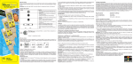
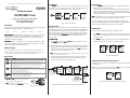
This Instruction Manual is also available for download at: www.eutechinst.com or www.4oakton.com
Switching On
Measurement
Press ON/OFF key to switch on the tester. The LCD shows the power-up sequence
as illustrated in Figure 2. When the tester is on, if you do not press a key for 8.5
minutes, the tester automatically switches off to conserve batteries.
1. Press the ON/OFF key to switch on the tester. The ‘MEAS’ indicators appears
when the tester is in measurement mode.
2. Dip the electrode into the test solution making sure that it is fully immersed.
Stir to clear any trapped air bubbles from the electrode and let the reading
stabilize. For plus models, you can opt for the cup style measurement by filling
the electrode cup with sample of test solution.
INSTRUCTION MANUAL
CAL
MEAS HOLD
EC/TDS/SALT Testr
pH%
ON/OFF
• TDSTestr11+
• SALTTestr11
Plus models (ECTestr11+ & TDSTestr11+) come with the user-replaceable cup type
sensor and have additional features such as Multi-range measurement, up to 3-point
calibration and higher resolution measurement.
Before You Begin
Remove the electrode’s protective cap. Soak the electrode for a few minutes in
alcohol to remove any oil stains on the electrodes which will affect the accuracy of
the tester. Rinse thoroughly with de-ionized water and shake off dry.
Key Functions
°C/°F
HOLD
Function
- Power on and off the tester
(The tester automatically switches of, if no button is pressed for 8.5 seconds)
- In measurement mode, temperature reading switches between Celsius &
Fahrenheit
- In calibration mode, switches the tester to temperature calibration mode
- In temperature calibration mode, exits calibration mode without confirming
calibrated values
- In measurement mode, switches to hold mode freezing the display.
- In hold mode, switches back to measurement mode
- In manual calibration and temperature calibration modes, exits calibration mode
without confirming calibrated values
- In range selection mode, selects a range
- In measurement mode, enters calibration mode
- In calibration mode, adjusts the calibration values
- In hold mode, enters TDS factor setting mode
- In TDS factor setting mode, adjusts TDS factor
Note: INC & DEC keys are located inside the
battery compartment.. Refer figure 1.
Note: For ECTestr11 & ECTestr11+ models, the
caption of HOLD key is ‘HOLD/ENT’
-1-
0.0
uS
ms
Au o
26.8
Selected range &
upper limit of the range
Note: The LCD indicates ‘Or’ (over range) if the reading is outside the selected
range. If this occurs, select an appropriate range to suit the reading.
°C
Measurement
mode
3. The upper display shows the main reading (conductivity/TDS/Salt) of the
solution, automatically temperature compensated (ATC) to normalized temperature
of 25°C. The lower display shows the temperature of the solution.
Figure 2: Power Up Sequence
Non-plus models (ECTestr11, TDSTestr11 & SALTTestr11) come with user-replaceable
two-pin type sensor and have many user friendly features such as Dual-range
measurement, the Hold function, Automatic Temperature Compensation (ATC) and
Self-Diagnostic Messaging capabilities.
K ey
20.00
Model number &
software revision number
Thank you for selecting microprocessor-based waterproof EC / TDS / SALT tester with
large dual line display. You have one of the following models:
• TDSTestr11
Ec.p
°C
°F
Introduction
• ECTestr11+
MEAS
S R.mV °C °F
Large Screen Waterproof Multi Range
Conductivity/TDS/Salt Tester
with Temperature Display
• ECTestr11
ATC
ATC
pp m
Range Selection
Depending on the selected model, you can set the tester to limit its reading to a
particular measuring range (PU, LO or HI) or full scale (AUTO). The default setting
is AUTO. When you select a range other than AUTO, the tester can be calibrated
only for that particular range. If you try to measure a sample which has a higher
conductivity/TDS value than that of the selected measuring range, the LCD shows
ica
tions section for available ranges of the
‘OR’ error message. Refer Specif
Specifica
ications
selected model.
To select a rrang
ang
e:
ange:
1. Switch off the tester. Press and hold °C/°F key and then switch on the tester
using ON/OFF key. Release °C/°F key.
2. The tester goes to range selection mode. The LCD shows the currently selected
Range (the default is AUTO) in the lower display. The upper display shows the
maximum possible reading for the selected range. Press HOLD key repeatedly
until you see the required range (PU, LO or HI).
Note: If no key is pressed within 5 seconds, LCD shows power-up sequence and
tester goes to measurement mode.
3. The tester automatically confirms the last selection if no key is pressed for 5
seconds. Upper display momentarily shows ‘CO’. The LCD shows power-up
sequence and the tester goes to measurement mode.
This feature lets you freeze the display for a delayed observation.
1. Press HOLD key to freeze the measurement. The tester goes to hold mode and
‘HOLD’ indicator is displayed in LCD. The measurements are frozen and the ‘MEAS’
indicator disappears.
2. Press HOLD key again to release the measurement. The ‘HOLD’ indicator is no
longer displayed. The tester goes back to measurement mode.
ATC
MEAS
ppm
1500
26.8
ATC
HOLD
HOLD
ppm
1500
°C
26.8
Measurement
mode
ATC
HOLD
MEAS
ppm
1535
°C
26.2
HOLD mode
°C
Measurement
mode
Figure 4: HOLD Function
Temperature Unit of Measurement Selection
This feature lets you set the unit of measurement of temperature to either Celsius (°C)
or Fahrenheit (°F).
2
1
Tester
Off
2
HOLD
ENT
200.0
2000
Au o
PU
LO
us
2
HOLD
ENT
20.00
ms
ON/OFF
2
HOLD
ENT
°C/ °F
us
Press & hold °C/°F
key and switch on
the tester
20.00
When the tester is in the measurement mode, press °C/°F button. The temperature
display toggles between the Celsius and Fahrenheit reading.
ms
HI
ATC
MEAS
5 seconds
Power-up
Sequence
+
Auto confirmation occurs for
the last selected range
if no key is pressed for 5 sec.
-
HOLD Function
3
CO
HI
ppt
°C/ °F
6.00
25.5
ppt
6.00
°C
78.0
°F
Figure 5: Temperature unit of measurement selection
Figure 3: Range selection sequence from AUTO to HI for ECTestr11+
Figure 1: Battery compartment
-2-
ATC
MEAS
-3-
About Calibration
2
To ensure higher accuracy, the tester must be calibrated on a regular basis.
Calibration can be manual or automatic (only for ECTestr11 & ECTestr11+); calibration
can be 1-point or multi-point. You can choose any combination of the above two
options for calibration. If you calibrate the tester for 1-point, the calibration is applied
for all the measuring ranges. In applications where you need higher accuracy, and
when you intend to measure values in more than one range, it is recommended to
select multi-point calibration.
Tester
Off
ON/OFF
The factory default is Automatic calibration (Auto). You can enable or disable
automatic calibration as described below (for only ECTestr11 & ECTestr11+ models).
Selection of 1-point or Multi-point Calibration
The factory default is 1-point Calibration. For higher accuracy, it is recommended that
you calibrate the tester for multiple ranges if you intend to measure values in multiple
ranges. You can enable or disable multi-point calibration as described below.
Note: If you have selected a specific measuring range for the tester, selecting multipoint calibration has no meaning, as the tester can only be calibrated for 1-point
for the selected range. Set the tester to ‘AUTO’ measuring range if you wish to
calibrate multi-points.
To ena
ulti-point calibr
enabble/disa
le/disabble auto calibr
calibraation and m
multi-point
calibraation:
1. Switch off the tester. Press and hold INC key and then switch on the tester using
ON/OFF key.
2. The tester goes to auto calibration selection mode. The lower display shows ‘A.CAL’
and the upper display blinks the current choice (‘Yes’ or ‘No’).
Note: This mode is available only for ECTestr11 & ECTestr11+ models. For other
models, go directly to 1-point selection mode, described in step 4 below.
Press INC or DEC key to select ‘Yes’ (to enable auto calibration) or ‘No’ (to disable
auto calibration)
Note: Press °C/°F key, if you wish to skip this setting without confirming changes.
Note
Note: Press °C/°F key twice, if you wish to return to measurement mode without
confirming changes.
3. Press HOLD/ENT key to confirm the selection. The display shows ‘CO’.
4. The tester goes to 1-point calibration selection mode. The lower display shows
‘1.Pnt’ and the upper display blinks the current choice (‘Yes’ or ‘No’).
Press INC or DEC key to select ‘Yes’ (to enable 1-point calibration) or ‘No’ (to
disable 1-point calibration, i.e. to enable multi-point calibration).
Note: Press °C/°F key if you wish to skip this setting without confirming.
5. Press HOLD/ENT key to confirm the selection. The display shows ‘CO’ for few
seconds and then shows power-up sequence The tester goes to measurement
mode.
-4-
4
After
1 sec.
YES
CO
A.CAL
A.CAL
5
HOLD
ENT
YES
CO
4
2
Power-up
Sequence
A.CAL
Note: If you have selected a specific measuring range for the tester, the lower display
shows the corresponding calibration standard value that matches the selected
measuring range.
4. Rinse the electrode with the calibration standard that you intend to calibrate and
then dip the electrode in the other beaker with same calibration standard. Swirl
gently to create a homogenous sample and allow time for the reading to stabilize.
Press & hold INC
key and switch on
the tester
Selection of Automatic or Manual Calibration
ECTestr11 & ECTestr11+ models support both automatic & manual calibration while
all other models have to be calibrated manually. In automatic calibration, the tester
automatically detects and verifies known conductivity standard solutions (84uS,
1413uS & 12.88mS) . In manual calibration, you can use non-standard solutions
which may be specific for your application.
3
HOLD
ENT
1
HOLD
ENT
HOLD
ENT
Figure 6: Selecting auto calibrtaion & 1-point calibration for ECTestr11+
Auto Calibration
Auto calibration feature is available only for conductivity in ECTestr11 &
ECTestr11+ models. Make sure that ‘auto calibration’ is enabled as described in
the previous section. Auto calibration is suitable if you use standard conductivity
solutions for calibration process.
If you selected 1-point calibration, you need to choose a calibration standard
corresponds to the selected measuring range of the tester listed below. If you
have selected multi-point calibration & AUTO measuring range, you can choose any
of the calibration standards listed below. During auto calibration, the tester
recognizes the calibration standard if its value is within 50% tolerance. For multipoint calibration (with AUTO measuring range), the tester automatically scans
through all possible calibration points until all of them are calibrated.
Note: For multi-point calibration, the lower display automatically locks at the
calibration standard value that closely matches. The tolerance range is ± 50% of
the calibration standard. The tester shows error message ‘Er.1’ if you try to calibrate
with a solution whose conductivity is outside the tolerance range.
Note: Press INC or DEC key if you wish to exit from auto calibration, during any of
the above steps.
5. Press HOLD/ENT key to confirm the calibration. LCD shows ‘CO’ for 2 seconds. The
calibration is complete and the tester returns to measurement mode, if this is a 1point calibration.
6. For multi-point calibration, the tester goes to the next calibration point, lower
display showing next calibration standard values. Rinse the electrode in de-ionized
water and repeat step 4 & 5 to continue calibrating with next calibration standard
solution.
Note: The tester shows error message ‘Er.0’ and returns to measuring mode if the
temperature of the calibration solution is not within 0°C to 50°C.
Note: The tester shows error message ‘Er.1’ if you press HOLD/ENT key before the
tester recognizes the calibration standard.
2
CAL
1
Selected Measuring Range
Calibration Standard
PU (0 to 200.0 uS/cm)
84 us
LO (0 to 2000 uS/cm)
1413 uS
HI (0 to 20.00 mS/cm)
12.88 mS
AUTO
84 us, 1413 uS, 12.88 mS
Measurement
Mode
OR
3
CAL
ATC
CAL
4
CAL
ATC
ATC
5
CAL
HOLD
ENT
ATC
0.0
1410
1410
1413
1413
CO
uS
Displayed for
2 seconds and
tester goes to
calibration mode
3
CAL
ATC
uS
uS
Confirmation of 1st point
Tester dipped in
displayed for
1413 uS std. solution
2 seconds
and automatically detects
the calibration std.
0.0
uS
To pr
ds:
preepar
paree calibr
calibraation standar
standards:
12.88
The two calibration stds. values
displayed sequentially until
tester finds a matching solution
within ± 50% tolerance.
Use fresh calibration standard solutions listed in the above table. Prepare each
solution in two beakers - one for rinsing and the other for calibration. Rinse the
electrode in de-ionized water before calibration.
6
CAL
To be
gin automa
tic calibr
begin
automatic
calibraation:
1. Switch on the tester. Make sure the tester is in measuring mode. Press INC or
DEC key to enter conductivity calibration mode.
2. ‘CAL’ indicator appears in LCD. The display briefly shows ‘CAL’ and the number
of points the tester will be calibrated.
3. The upper display shows the conductivity reading and the lower display
sequentially shows calibration standard values 1413 uS & 12.88 mS (for
ECTestr11) or 84 uS, 1413 uS & 12.88 mS (for ECTestr11+) if the
measuring range of the tester is set to AUTO.
-5-
ATC
CAL
ATC
CAL
HOLD
ENT
ATC
1410
12.80
12.80
12.88
12.88
CO
mS
mS
mS
Measurement
Mode
Confirmation of 2nd point
Tester dipped in
The next calibration std.
displayed for
displayed until tester finds 12.88 mS std. solution
2 seconds
& automatically detects
a close match within
the calibration std.
± 50% tolerance
Figure 7: Two-point automatic calibration sequence for ECTestr11
-6-
5. For multi-point calibration rinse the electrode in de-ionized water and repeat
step the above steps with another standard solution.
Manual Calibration
In manual calibration, the tester allows 1-point calibration for each measuring range.
You can use customized calibration solutions with known conductivity/TDS values to
calibrate the tester. . The following table shows acceptable conductivity/TDS ranges of
calibration solutions for each measuring range. Make sure your calibration solutions
are within the given ranges.
Selected
Measuring Range
PU
LO
HI
AUTO
2
Measurement
Mode
Acceptable Calibration Standard Range
Conductivity
TDS/Salt
2.0 - 200.0 uS/cm
200 - 2000 uS/cm
2.00 - 20.00 mS/cm
OR
2.0 - 200.0 ppm
200 - 2000 ppm
1.00 - 10.00 ppt
Select a calibration standard nearer to application sample
3
ATC
CAL
ATC
4
After
5 sec.
CAL
1400
1410
1410
Displayed for
2 seconds and
Tester goes to
Calibration mode
Tester dipped in
1413 uS std. solution
Upper display reading
Adjusted to the actual
Conductivity value of
Calibration std. solution
uS
1413
uS
CAL
Temperature calibration need not be performed every time, unless the temperature
reading differs from that of an accurate thermometer. If temperature calibration is
performed, Conductivity/TDS/Salt calibration is mandatory.
ATC
1413
uS
CO
Confirmation
displayed for
2 seconds
1. Switch on the tester. Make sure the tester is in measuring mode. If required,
press °C/°F key to select the desired unit of measurement for temperature
(Celsius or Fahrenheit). Dip the tester into a solution of known temperature
and allow time for the temperature reading to stabilize.
2. Press INC or DEC key to bring the tester to the calibration mode. CAL’ indicator
appears in LCD. Immediately press °C/°F key to switch to the temperature
calibration mode.
Figure 8: One-point manual calibration sequence for ECTestr11+
To pr
ds:
preepar
paree calibr
calibraation standar
standards:
Use fresh calibration solutions. Measure conductivity/TDS values of the solution with a
meter known to be accurate. Prepare each solution in two beakers - one for rinsing
and the other for calibration. Rinse the electrode in de-ionized water before
calibration.
Note: When you enter calibration mode, if the conductivity/TDS/salt reading is outside
the specified range (Or), the tester shows ‘Er.1’ error message. You can still proceed
to the temperature calibration mode by pressing °C/°F key immediately. If the °C/°F
key is not pressed within 2 seconds, the tester exits the calibration mode and returns
to the measurement mode.
TDS Factor Setting
TDS factor is only applicable for TDSTestr11 & TDSTestr11+ models.
The factory default TDS factor is 0.71. You can adjust the TDS factor to suit
different samples of your applications.
To be
gin man
ual calibr
begin
manual
calibraation:
1. Switch on the tester. Make sure the tester is in measuring mode. Rinse the
electrode with the calibration standard that you intend to calibrate and then dip
the electrode in the other beaker with same calibration standard. Swirl gently to
create a homogenous sample and allow time for the reading to stabilize.
2. Press INC or DEC key to enter calibration mode. The ‘CAL’ indicator appears in
LCD. The display briefly shows ‘CAL’ and the number of points the tester will be
calibrated.
3. The upper display shows the measured conductivity/TDS reading of the solution
based on previous calibration (if any) and the lower display shows the default
(uncalibrated) conductivity/TDS reading.
2
2
ATC
1
Measurement
Mode
To cchang
hang
actor
hangee TDS ffactor
actor::
1. Switch on the tester. Make sure the tester in measurement mode. Press HOLD
key to bring the tester to the HOLD mode.
2. Press INC or DEC key to enter the TDS factor setting mode.
3. The upper & lower displays of LCD show the last configured TDS factor. The
upper display is adjustable. Use the INC or DEC key to adjust the TDS factor.
The adjustable range is 0.4 to 1.0
Set required unit of
measurement for
temperature
CAL
4. Wait for 5 seconds for the tester to automatically confirm the new setting by
displaying ‘CO’ and return to the measurement mode.
Use INC and DEC keys to adjust the upper display to the correct conductivity/TDS
value of the calibration solution.
2
1
Measurement
Mode
Note: The calibration adjustment window is ± 50% from the default reading.
HOLD
HOLD
3
ppt
6.35
26.8
Note: If you do not press INC or DEC key within 5 seconds, the tester shows the
confirmation ‘CO’ and returns to the measurement mode. However, the tester is
not calibrated to new values yet. The old calibration is still active. If this happens,
press INC or DEC key once again to enter calibration mode.
3
ATC
HOLD mode
°C
OR
0.71
0.50
7.50
mS
26.8
°C
Dipped in a solution
of known temperature
OR
0.71
0.71
TDS Factor setting mode
Figure 9: TDS Factor setting
CAL
7.50
26.8
7.50
26.8
Calibration
mode
Temperature Calibration mode
mS
°C
OR
27.5
°C
26.8
°C
°C
4
CAL
ATC
MEAS
7.50
mS
27.5
27.5
°C
CO
°C
Measurement
mode
Confirmation
displayed for
2 seconds
0.50
CO
Confirmation
displayed for
2 seconds
3. The upper display shows the measured temperature reading based on the last set
offset (if any) and the lower display shows the default (uncalibrated) temperature
reading based on factory settings. Use INC and DEC keys to adjust the upper
temperature reading to the known temperature value of the solution.
Notes: The temperature adjustment window is ± 5°C (± 9°F) from the default reading.
4. Wait for 5 seconds for the tester to automatically confirm the temperature
calibration value by displaying ‘CO’ and return to the measurement mode.
Note: To exit temperature calibration mode without confirming the calibration, press
°C/°F key or HOLD/ENT key before the automatic confirmation takes place.
.
Note: The tester shows error message ‘Er.0’ and returns to measuring mode if the
temperature of the solution is not within 0°C to 50°C.
Note: To exit calibration mode without confirming the calibration, press HOLD/ENT
key before the automatic confirmation takes place.
Note: The tester shows error message ‘Er.0’ and returns to measuring mode if the
temperature of the calibration solution is not within 0°C to 50°C.
-7-
3
3
CAL
°C/ °F
Figure 10: Temperature calibration sequence
4
After
5 sec.
ATC
MEAS
Note: If you do not press INC or DEC key within 5 seconds, the tester shows the
confirmation ‘CO’ and returns to measurement mode.
Note: The tester shows error message ‘Er.1’ :
(a) If the reading is over range (Or) of selected measuring range of the tester ,
or
(b) If the default (uncalibrated) reading is not within the acceptable calibration
standard range.
4. Wait for 5 seconds for the tester to automatically confirm the calibration by
displaying ‘CO’ and return to the measurement mode.
3
CAL
ATC
1
Temperature Calibration
-8-
-9-
Reset
Electrode Maintenance
Reset option allows you to restore the calibration and other parameters back to
factory default settings.
1. Always keep the sensor electrodes clean. Rinse the electrodes with de-ionized
water and wipe them dry with clean cloth before storing with its protective cap.
For cup type electrodes, remove the white plastic cup and insert to thoroughly
clean viscous solutions. Never scratch electrodes with a hard substance.
1. Switch off the tester. Press and hold the HOLD key and then switch on the tester
using ON/OFF key. Release HOLD key.
2. The lower display shows ‘rSt’ (reset) and the upper display blinks ‘No’. Use INC
or DEC key to select ‘Yes’ (to proceed with resting) or ‘No’ (to quit without
resetting).
Note: Press °C/°F key if you wish to skip to measurement mode without making any
selection.
3. Press HOLD key to confirm your selection. LCD shows ‘CO’. If ‘Yes’ is selected, the
tester resets to its factory default values as listed below. LCD shows power-up
sequence and tester goes to measurement mode.
2
1
HOLD
HOLD
CO
2. For better performance, soak the electrode in alcohol for 10 to 15 minutes
and rinse with de-ionized water before starting any measurement process.
This is to remove dirt and oil stains on the electrode which may affect the
accuracy of the measurements.
Electrode Replacement
When the tester fails to calibrate or gives fluctuating readings in calibration
standards, you need to change the electrode module. You can replace the
electrode module at a fraction of the cost of a new tester.
1. With dry hands, grip the ribbed tester collar with electrode facing you. Twist the
collar counter clockwise (see Figure13-A). Save the ribbed tester collar and
O-ring for later use.
2. Pull the old electrode module away from the tester.
3. Align the four tabs of the new electrode module so that they match the four
slots on the tester (see Figure 13-B).
4. Gently push the module into the slots to sit it in position. Push the smaller
O-ring fully onto the new electrode module. Push the collar over the module
and thread it into place by firmly twisting clockwise.
3
Tester
Off
Accessories
Power-up
Sequence
ON/OFF
Press & hold HOLD
key and switch on
the tester
2
YES
Item
Order Code
ECTESTR, TDSTESTR & SALTESTR
replacement sensor
TDSSENSOR
ECTESTR+ & TDSTESTR+
replacement sensor
TDSSENSORPLUS
Warranty
The waterproof testers are warranted to be free from manufacturing defects for 1 year
and electrode module for 6 months, unless otherwise specified. If repair, adjustment or
replacement is necessary and has not been the result of abuse or misuse within the
time period specified, please return the tester - freight prepaid - and correction will be
made without charge. Out of warranty products will be repaired on a charge basis.
Return of Items
Authorization must be obtained from your distributor before returning items for any
reason.
When applying for authorization, please include information regarding the reason the
item(s) are to be returned.
Note: Eutech Instruments/Oakton Instruments reserve the right to make improvements
in design, construction and appearance of products without notice. Prices are subject
to change without notice.
Note: It is necessary that you recalibrate the tester prior to measurement after
an electrode replacement.
HOLD
A
B
Rotate ribbed collar
away from you
Figure 11: Resetting sequence
Insert Electrode Module
Large
O-Ring
Specifications
Model
Parameter
Factory Default
User calibration (conductivity/TDS/salt)
(Reset)
Temperature unit of measurement
Celsius (°C)
Temperature offset
0
Auto calibration (for ECTestr11 & ECTester11+)
Enable
1-point calibration
Enable
Conductivity calibration factor (for ECTestr11 & ECTester11+)
1.0
TDS factor (for TDSTestr11 & TDSTester11+)
0.71
Range:
Ribbed collar
Small Tab
Large Tab
Self-Diagnostic Messages
3 Bars indicates Battery is full (100%)
Changing Batteries
2 Bars indicates 50% of the battery life is left
1 Bar indicates 25% of the battery life is left
Blinking battery casing indicates the need to replace
batteries with fresh ones as specified by manufacturer
Over range /
Under range
signal
+
-
Or / Ur
(Still)
ATC / Or /
Ur (Blinking)
Plastic
Ribbon
Figure 11: Battery compartment
-10-
Small
O-Ring
Figure 13: Removing collar & inserting electrode
Low battery
indicator
Replace the batteries when the low battery indicator
starts blinking.
1. Open the battery compartment lid (with attached
lanyard loop).
2. Remove old batteries by pulling plastic ribbon.
Replace with fresh ones. Note polarity as shown in
figure 11.
Ribbed collar
Error
Message
Er
.0
Er.0
Er
.1
Er.1
The sensor electrodes short circuited
Replacement sensor is not connected properly to the
tester during sensor replacement
Measured value or temperature value exceeds the specified
maximum or minimum value
Blinking ‘ATC’, ‘Or’ or ‘Ur’ indicates that there is a shor t
or open circuit at the built in temperature sensor
Calibration error due to temperature value not within the
specified range
Calibration error due to Conductivity/TDS/Salt value not
within the specified calibration standard range
-11-
Resolution:
ECT
estr11
ECTestr11
ECT
estr11+
ECTestr11+
TDST
estr11
TDSTestr11
TDST
estr11+
TDSTestr11+
PU
LO 0 to 2000 uS/cm
HI 0 to 20.00 mS/cm
PU
LO
10 uS/cm
HI
0.10 mS/cm
Accuracy
Calibration Type
Calibration Points
Calibration Window
Calibration
PU
Standard Range:LO
(Manual)
HI
Sensor Type
TDS Factor
Temperature
Range in °C
Range in °F
Resolution
Accuracy
Calibration point
Calibration Window
ATC
Temp Coefficient
Normalization Temp
Auto Off
Operating Temp
Power Battery
Battery Life
LCD Display
Dimensions
Weight
0 to 200.0 uS/cm
0 to 200.0 ppm
0 to 2000 uS/cm
0 to 2000 ppm
0 to 2000 ppm
0 to 20.00 mS/cm
0 to 10.00 ppt
0 to 10.00 ppt
0.1 uS/cm
0.1 ppm
1 uS/cm
10 ppm
1 ppm
0.01 mS/cm
0.10 ppt
0.01 ppm
± 1% of Full Scale
Auto or Manual
Auto or Manual
Manual
Manual
1 or 2 points
1, 2 or 3 points
1 or 2 points
1, 2 or 3 points
± 50% from each point
2.0 - 200.0 uS/cm
2.0 - 200.0 ppm
200 - 2000 uS/cm 200 - 2000 uS/cm
200 - 2000 ppm
200 - 2000 ppm
2.00 - 20.00 mS/cm 2.00 - 20.00 mS/cm
1.00 - 10.00 ppt
1.00 - 10.00 ppt
Two-pin
Cup
Two-pin
Cup
0.4 to 1.0 (Default 0.71)-
SAL
TT
estr11
SALTT
TTestr11
0 to 10.00 ppt
0.10 ppt
Manual
1 point
1.00 - 10.00 ppt
Two-pin
0.0 to 50.0°C
32.0 to 122°F
0.1°C (0.1°F)
±0.5°C (±0.9°F)
1 point
± 5°C (± 9°F)from factory default
0 to 50°C
2% per °C
25.0°C
8.5 minutes after last key press
0 to 50°C
4 X 1.5V”A76" micro alkaline battery
>150 hrs
Custom Dual Display27mm(H)X21mm(W)
Tester: 16.5 cm X 3.8 cm; 90g
Boxed: 22cm X 6cmX 5cm; 170 g
68X068056 Rev 2 May 06