1
SCALANCE WLC711
User Guide, V8.11
07/2012
C79000-G8976-C260-03
Legal Information
Warning notice system
This manual contains notices you have to observe in order to ensure your personal safety, as well as to
prevent damage to property. The notices referring to your personal safety are highlighted in the manual by
a safety alert symbol, notices referring only to property damage have no safety alert symbol. These
notices shown below are graded according to the degree of danger.
DANGER
indicates that death or severe personal injury will result if proper precautions are not taken.
WARNING
indicates that death or severe personal injury may result if proper precautions are not taken.
CAUTION
with a safety alert symbol, indicates that minor personal injury can result if proper precautions are not
taken.
CAUTION
without a safety alert symbol, indicates that property damage can result if proper precautions are not
taken.
NOTICE
indicates that an unintended result or situation can occur if the relevant information is not taken into
account.
If more than one degree of danger is present, the warning notice representing the highest degree of danger will be used. A notice warning of injury to persons with a safety alert symbol may also include a warning relating to property damage.
Qualified Personnel
The product/system described in this documentation may be operated only by personnel qualified for the
specific task in accordance with the relevant documentation, in particular its warning notices and safety
instructions. Qualified personnel are those who, based on their training and experience, are capable of
identifying risks and avoiding potential hazards when working with these products/systems.
Proper use of Siemens products
Note the following:
WARNING
Siemens products may only be used for the applications described in the catalog and in the relevant
technical documentation. If products and components from other manufacturers are used, these must be
recommended or approved by Siemens. Proper transport, storage, installation, assembly, commissioning, operation and maintenance are required to ensure that the products operate safely and without any
problems. The permissible ambient conditions must be complied with. The information in the relevant
documentation must be observed
Trademarks
All names identified by ® are registered trademarks of Siemens AG. The remaining trademarks in this
publication may be trademarks whose use by third parties for their own purposes could violate the rights
of the owner.
Disclaimer of Liability
We have reviewed the contents of this publication to ensure consistency with the hardware and software
described. Since variance cannot be precluded entirely, we cannot guarantee full consistency. However,
the information in this publication is reviewed regularly and any necessary corrections are included in subsequent editions.
Siemens AG
Industry Sector
Postfach 48 48
90026 NÜRNBERG
GERMANY
order number:C79000-G8976-C260-03
07/2012
Copyright © Siemens AG 2012
Technical data subject to change
Contents
About This Guide
Intended Audience .............................................................................................................................................xi
How to Use This Guide ......................................................................................................................................xi
Formatting Conventions ................................................................................................................................... xii
Additional Documentation ................................................................................................................................ xiii
Chapter 1: Overview of the SCALANCE WLC711 Solution
Introduction ..................................................................................................................................................... 1-1
The SCALANCE IWLAN Controller .......................................................................................................... 1-1
Conventional Wireless LANs .......................................................................................................................... 1-2
Elements of the SCALANCE WLC711 Solution ............................................................................................. 1-3
SCALANCE WLC711 and Your Network ....................................................................................................... 1-5
Network Traffic Flow ................................................................................................................................ 1-7
Network Security ...................................................................................................................................... 1-8
Virtual Network Services .......................................................................................................................... 1-9
VNS Components .................................................................................................................................. 1-11
Routing ................................................................................................................................................... 1-13
Mobility and Roaming ............................................................................................................................. 1-13
Network Availability ................................................................................................................................ 1-13
Quality of Service (QoS) ........................................................................................................................ 1-14
Chapter 2: Configuring the SCALANCE IWLAN Controller
System Configuration Overview ..................................................................................................................... 2-1
Logging on to the SCALANCE IWLAN Controller .......................................................................................... 2-4
Wireless Assistant Home Screen ................................................................................................................... 2-4
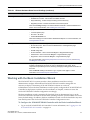
Working with the Basic Installation Wizard ..................................................................................................... 2-7
Configuring the SCALANCE IWLAN Controller for the First Time ................................................................ 2-12
Changing the Administrator Password ................................................................................................... 2-13
Applying Product License Keys .............................................................................................................. 2-13
Setting Up the Data Ports ...................................................................................................................... 2-14
Setting Up Internal VLAN ID and Multicast Support ............................................................................... 2-20
Setting Up Static Routes ........................................................................................................................ 2-21
Setting Up OSPF Routing ...................................................................................................................... 2-23
Configuring Filtering at the Interface Level ............................................................................................ 2-26
Protecting the Controller’s Interfaces and Internal Captive Portal Page ................................................ 2-30
Configuring the Login Authentication Mode ........................................................................................... 2-36
Configuring SNMP ................................................................................................................................. 2-46
Configuring Network Time ...................................................................................................................... 2-49
Configuring Secure Connections ........................................................................................................... 2-52
Configuring DNS Servers for Resolving Host Names of NTP and RADIUS Servers ............................. 2-53
Using an AeroScout/Ekahau Location-based Solution ................................................................................. 2-54
Additional Ongoing Operations of the System .............................................................................................. 2-58
Chapter 3: Configuring the Wireless AP
Wireless AP Overview .................................................................................................................................... 3-1
Siemens Wireless 802.11n AP ................................................................................................................. 3-4
Wireless AP International Licensing ......................................................................................................... 3-8
Wireless AP Default IP Address and First-time Configuration ................................................................. 3-8
Assigning a Static IP Address to the Wireless AP ................................................................................... 3-9
SCALANCE WLC711
User Guide, V8.11, 07/2012, C79000-G8976-C260-03
i
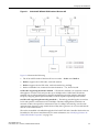
Discovery and Registration Overview ............................................................................................................. 3-9
Wireless AP Discovery ........................................................................................................................... 3-10
Registration After Discovery ................................................................................................................... 3-12
Understanding the Wireless AP LED Status .......................................................................................... 3-12
Configuring the Wireless APs for the First Time .................................................................................... 3-15
Defining Properties for the Discovery Process ....................................................................................... 3-16
Methods of Connecting and Powering a Wireless AP ............................................................................ 3-18
Adding and Registering a Wireless AP Manually ......................................................................................... 3-18
Configuring Wireless AP Settings ................................................................................................................. 3-19
Modifying a Wireless AP’s Status .......................................................................................................... 3-19
Configuring a Wireless AP’s Properties ................................................................................................. 3-21
AP Properties Tab Configuration ........................................................................................................... 3-21
Assigning Wireless AP Radios to a VNS ............................................................................................... 3-25
Configuring Wireless AP Radio Properties ............................................................................................ 3-26
Setting Up the Wireless AP Using Static Configuration ......................................................................... 3-39
Configuring Telnet/SSH Access ............................................................................................................. 3-42
Configuring VLAN Tags for Wireless APs .................................................................................................... 3-44
Setting Up 802.1x Authentication for a Wireless AP .............................................................................. 3-44
Setting Up 802.1x Authentication for Wireless APs Using Multi-edit ..................................................... 3-50
Configuring the Default Wireless AP Settings ........................................................................................ 3-53
Modifying a Wireless AP’s Properties Based on a Default AP Configuration ............................................... 3-66
Modifying the Wireless AP’s Default Setting Using the Copy to Defaults Feature ....................................... 3-66
Configuring Multiple Wireless APs Simultaneously ...................................................................................... 3-66
Configuring Co-located APs in Load Balance Groups .................................................................................. 3-69
How Availability Affects Load Balancing ................................................................................................ 3-74
Load Balance Group Statistics ............................................................................................................... 3-75
Configuring an AP Cluster ............................................................................................................................ 3-75
Performing Wireless AP Software Maintenance ........................................................................................... 3-76
Chapter 4: Configuring Topologies
Topology Overview ......................................................................................................................................... 4-1
Configuring the Admin Port ............................................................................................................................ 4-2
Configuring a Basic Data Port Topology ........................................................................................................ 4-4
Enabling Management Traffic ......................................................................................................................... 4-5
Layer 3 Configuration ..................................................................................................................................... 4-6
IP Address Configuration ......................................................................................................................... 4-6
DHCP Configuration ................................................................................................................................. 4-8
Defining a Next Hop Route and OSPF Advertisement ........................................................................... 4-10
Exception Filtering ........................................................................................................................................ 4-11
Multicast Filtering .......................................................................................................................................... 4-15
Chapter 5: Configuring Policies
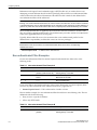
Policy Overview .............................................................................................................................................. 5-1
Configuring VLAN and Class of Service for a Policy ...................................................................................... 5-1
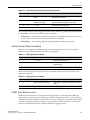
Filtering Rules ................................................................................................................................................. 5-3
Filtering Rules for a Non-authenticated Filter ........................................................................................... 5-3
Non-authenticated Filter Examples .......................................................................................................... 5-4
Authenticated Filter Examples ................................................................................................................. 5-5
ICMP Type Enforcement .......................................................................................................................... 5-5
Filtering Rules for a Default Filter ............................................................................................................. 5-6
Defining Filter Rules for Wireless APs ..................................................................................................... 5-7
Configuring Filter Rules ............................................................................................................................ 5-7
ii
SCALANCE WLC711
C79000-G8976-C260-03, 07/2012, User Guide, V8.11
Chapter 6: Configuring WLAN Services
WLAN Services Overview .............................................................................................................................. 6-1
Third-party AP WLAN Service Type ............................................................................................................... 6-2
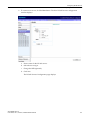
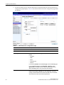
Configuring a Basic WLAN Service ................................................................................................................ 6-2
Configuring Privacy ........................................................................................................................................ 6-8
About Wi-Fi Protected Access (WPA V1 and WPA V2) ........................................................................... 6-9
Wireless 802.11n APs and WPA Authentication .................................................................................... 6-10
WPA Key Management Options ............................................................................................................ 6-11
Configuring WLAN Service Privacy ........................................................................................................ 6-11
Configuring Accounting and Authentication .................................................................................................. 6-14
Vendor Specific Attributes ...................................................................................................................... 6-14
Defining Accounting Methods for a WLAN Service ................................................................................ 6-15
Configuring Authentication for a WLAN Service .................................................................................... 6-17
MAC-Based Authentication for a WLAN Service ................................................................................... 6-18
Assigning RADIUS Servers for Authentication ....................................................................................... 6-18
Defining the RADIUS Server Priority for RADIUS Redundancy ............................................................. 6-21
Configuring Assigned RADIUS Servers ................................................................................................. 6-21
Defining a WLAN Service with No Authentication .................................................................................. 6-24
Configuring Captive Portal for Internal Authentication ........................................................................... 6-25
Configuring the QoS Policy .......................................................................................................................... 6-35
Defining Priority Level and Service Class .............................................................................................. 6-36
Defining the Service Class ..................................................................................................................... 6-37
Configuring the Priority Override ............................................................................................................ 6-38
QoS Modes ............................................................................................................................................ 6-38
Chapter 7: Configuring a VNS
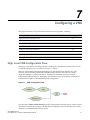
High Level VNS Configuration Flow ............................................................................................................... 7-1
Controller Defaults ................................................................................................................................... 7-2
VNS Global Settings ....................................................................................................................................... 7-3
Defining RADIUS Servers and MAC Address Format ............................................................................. 7-4
Configuring RADIUS Attribute for Hybrid Policy Mode ............................................................................. 7-8
Configuring Dynamic Authorization Server Support ............................................................................... 7-11
Defining Wireless QoS Admission Control Thresholds .......................................................................... 7-12
Working with Bandwidth Control Profiles ............................................................................................... 7-15
Configuring the Global Default Policy .................................................................................................... 7-16
Configuring Egress Filtering Mode ......................................................................................................... 7-17
Using the Sync Summary ....................................................................................................................... 7-19
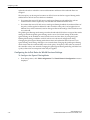
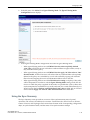
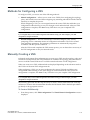
Methods for Configuring a VNS .................................................................................................................... 7-21
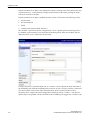
Manually Creating a VNS ............................................................................................................................. 7-21
Creating a VNS Using the Wizard ................................................................................................................ 7-23
Creating a Voice VNS Using the VNS Wizard ....................................................................................... 7-23
Creating a Data VNS Using the VNS Wizard ......................................................................................... 7-32
Creating a Captive Portal VNS Using the VNS Wizard .......................................................................... 7-41
Enabling and Disabling a VNS ..................................................................................................................... 7-70
Renaming a VNS .......................................................................................................................................... 7-71
Deleting a VNS ............................................................................................................................................. 7-71
Chapter 8: Configuring Classes of Service
Classes of Service Overview .......................................................................................................................... 8-1
Configuring Classes of Service ...................................................................................................................... 8-1
CoS Rule Classification .................................................................................................................................. 8-4
Priority and ToS/DSCP Marking ..................................................................................................................... 8-5
Configuring ToS/DSCP Marking .............................................................................................................. 8-5
SCALANCE WLC711
User Guide, V8.11, 07/2012, C79000-G8976-C260-03
iii
Rate Limiting ................................................................................................................................................... 8-6
Chapter 9: Configuring Sites
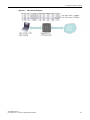
VNS Sites Overview ....................................................................................................................................... 9-1
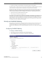
Configuring Sites ............................................................................................................................................ 9-1
Recommended Deployment Guidelines ......................................................................................................... 9-2
Defining Policies, CoS, and RADIUS Servers for Local RADIUS Authentication .................................... 9-2
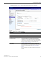
Radius Configuration ...................................................................................................................................... 9-5
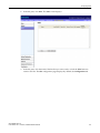
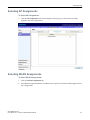
Selecting AP Assignments ............................................................................................................................. 9-7
Selecting WLAN Assignments ........................................................................................................................ 9-7
Chapter 10: Working with a Mesh Network
About Mesh .................................................................................................................................................. 10-1
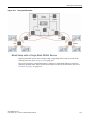
Simple Mesh Configuration .......................................................................................................................... 10-2
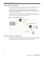
Wireless Repeater Configuration .................................................................................................................. 10-2
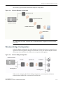
Wireless Bridge Configuration ...................................................................................................................... 10-3
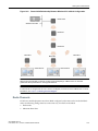
Examples of Deployment .............................................................................................................................. 10-4
Mesh WLAN Services ................................................................................................................................... 10-4
Mesh Setup with a Single Mesh WLAN Service .................................................................................... 10-5
Mesh Setup with Multiple Mesh WLAN Services ................................................................................... 10-6
Key Features of Mesh .................................................................................................................................. 10-7
Self-Healing Network ............................................................................................................................. 10-7
Tree-like Topology ................................................................................................................................. 10-8
Radio Channels ...................................................................................................................................... 10-9
Multi-Root Mesh Topology ................................................................................................................... 10-10
Link Security ......................................................................................................................................... 10-10
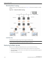
Deploying the Mesh System ....................................................................................................................... 10-10
Planning the Mesh Topology ................................................................................................................ 10-11
Provisioning the Mesh Wireless APs ................................................................................................... 10-11
Mesh Deployment Overview ................................................................................................................ 10-11
Connecting the Mesh Wireless APs to the Enterprise Network for Discovery and Registration .......... 10-11
Configuring the Mesh Wireless APs Through the SCALANCE IWLAN Controller ............................... 10-12
Connecting the Mesh Wireless APs to the Enterprise Network for Provisioning ................................. 10-16
Moving the Mesh Wireless APs to the Target Location ....................................................................... 10-16
Changing the Pre-shared Key in a Mesh WLAN Service ........................................................................... 10-16
Chapter 11: Working with a Wireless Distribution System
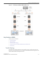
About WDS ................................................................................................................................................... 11-1
Simple WDS Configuration ........................................................................................................................... 11-2
Wireless Repeater Configuration .................................................................................................................. 11-2
Wireless Bridge Configuration ...................................................................................................................... 11-3
Examples of Deployment .............................................................................................................................. 11-4
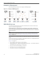
WDS WLAN Services ................................................................................................................................... 11-4
WDS Setup with a Single WDS WLAN Service ..................................................................................... 11-5
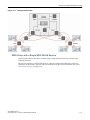
WDS Setup with Multiple WDS WLAN Services .................................................................................... 11-6
Key Features of WDS ................................................................................................................................... 11-7
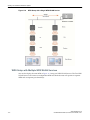
Tree-like Topology ................................................................................................................................. 11-7
Radio Channels ...................................................................................................................................... 11-9
Multi-Root WDS Topology .................................................................................................................... 11-10
Automatic Discovery of Parent and Backup Parent Wireless APs ....................................................... 11-10
Link Security ......................................................................................................................................... 11-11
Deploying the WDS System ....................................................................................................................... 11-11
Planning the WDS Topology ................................................................................................................ 11-11
iv
SCALANCE WLC711
C79000-G8976-C260-03, 07/2012, User Guide, V8.11
Provisioning the WDS Wireless APs .................................................................................................... 11-11
WDS Deployment Overview ................................................................................................................. 11-11
Connecting the WDS Wireless APs to the Enterprise Network for Discovery and Registration .......... 11-12
Configuring the WDS Wireless APs Through the SCALANCE IWLAN Controller ............................... 11-12
Assigning the Satellite Wireless APs’ Radios to the Network WLAN Services .................................... 11-17
Connecting the WDS Wireless APs to the Enterprise Network for Provisioning .................................. 11-18
Moving the WDS Wireless APs to the Target Location ........................................................................ 11-18
Changing the Pre-shared Key in a WDS WLAN Service ............................................................................ 11-19
Chapter 12: Availability and Session Availability
Availability ..................................................................................................................................................... 12-1
Events and Actions in Availability ........................................................................................................... 12-2
Availability Prerequisites ........................................................................................................................ 12-3
Configuring Availability Using the Availability Wizard ............................................................................ 12-3
Configuring Availability Manually ........................................................................................................... 12-5
Session Availability ....................................................................................................................................... 12-9
Events and Actions in Session Availability ........................................................................................... 12-11
Enabling Session Availability ............................................................................................................... 12-12
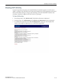
Viewing SLP Activity ................................................................................................................................... 12-19
Chapter 13: Configuring Mobility
Mobility Overview ......................................................................................................................................... 13-1
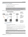
Mobility Domain Topologies ......................................................................................................................... 13-3
Configuring a Mobility Domain ...................................................................................................................... 13-4
Designating a Mobility Manager ............................................................................................................. 13-4
Designating a Mobility Agent .................................................................................................................. 13-5
Chapter 14: Working with Third-party APs
Define Authentication by Captive Portal for the Third-party AP WLAN Service ........................................... 14-1
Define the Third-party APs List ..................................................................................................................... 14-1
Define Filtering Rules for the Third-party APs .............................................................................................. 14-2
Chapter 15: Working with the Mitigator
Mitigator Overview ........................................................................................................................................ 15-1
Analysis Engine Overview ............................................................................................................................ 15-2
Enabling the Analysis Engine ....................................................................................................................... 15-2
Viewing the Mitigator Logs ........................................................................................................................... 15-3
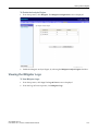
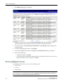
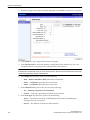
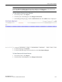
Running Mitigator Scans .............................................................................................................................. 15-4
Working with Mitigator Scan Results ............................................................................................................ 15-7
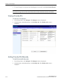
Viewing Mitigator Scan Results .............................................................................................................. 15-7
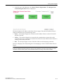
Adding an AP from the Scan Results to the List of Friendly APs ......................................................... 15-11
Deleting an AP from the Scan Results ................................................................................................. 15-11
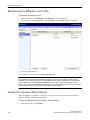
Viewing Friendly APs ........................................................................................................................... 15-12
Adding Friendly APs Manually ............................................................................................................. 15-12
Deleting Friendly APs ........................................................................................................................... 15-13
Modifying Friendly APs ........................................................................................................................ 15-13
Maintaining the Mitigator List of APs .......................................................................................................... 15-14
Viewing the Scanner Status Report ............................................................................................................ 15-14
Chapter 16: Working with Reports and Statistics
Available Reports and Statistics ................................................................................................................... 16-1
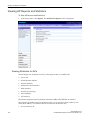
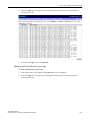
Viewing AP Reports and Statistics ............................................................................................................... 16-2
Viewing Statistics for APs ...................................................................................................................... 16-2
SCALANCE WLC711
User Guide, V8.11, 07/2012, C79000-G8976-C260-03
v
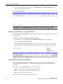
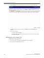
Viewing Load Balance Group Statistics ................................................................................................. 16-6
.Viewing Wireless AP Availability ........................................................................................................... 16-6
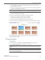
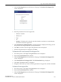
AP Inventory Reports ............................................................................................................................. 16-7
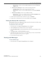
About Radio Preference/Load Control Statistics .................................................................................. 16-10
About Client Balancing Statistics Reports ............................................................................................ 16-11
Viewing Active Clients ................................................................................................................................ 16-12
Viewing Policy Filter Statistics .................................................................................................................... 16-13
Viewing Topology Statistics ........................................................................................................................ 16-14
Viewing Mobility Reports ............................................................................................................................ 16-16
Viewing Controller Status Information ........................................................................................................ 16-19
Viewing Routing Protocol Reports .............................................................................................................. 16-20
Call Detail Records (CDRs) ........................................................................................................................ 16-21
CDR File Naming Convention .............................................................................................................. 16-22
CDR File Types .................................................................................................................................... 16-22
CDR File Format .................................................................................................................................. 16-22
Viewing CDRs ...................................................................................................................................... 16-24
Backing Up and Copying CDR Files to a Remote Server .................................................................... 16-24
Chapter 17: Performing System Administration
Performing Wireless AP Client Management ............................................................................................... 17-1
Disassociating a Client ........................................................................................................................... 17-1
Blacklisting a Client ................................................................................................................................ 17-2
Defining SCALANCE W Wireless Assistant Administrators and Login Groups ............................................ 17-5
Chapter 18: Logs, Traces, Audits and DHCP Messages
SCALANCE IWLAN Controller Messages .................................................................................................... 18-1
Working with Logs ........................................................................................................................................ 18-2
Log Severity Levels ................................................................................................................................ 18-2
Viewing the SCALANCE IWLAN Controller Logs .................................................................................. 18-2
Viewing Wireless AP Logs ..................................................................................................................... 18-3
Viewing Login Logs ................................................................................................................................ 18-4
Working with a Tech Support File .......................................................................................................... 18-6
Viewing Wireless AP Traces ........................................................................................................................ 18-8
Viewing the Wireless 802.11n AP Traces .............................................................................................. 18-9
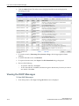
Viewing Audit Messages .............................................................................................................................. 18-9
Viewing the DHCP Messages .................................................................................................................... 18-10
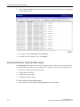
Viewing the NTP Messages ....................................................................................................................... 18-11
Viewing Software Upgrade Messages ........................................................................................................ 18-12
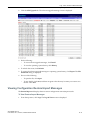
Viewing Configuration Restore/Import Messages ...................................................................................... 18-13
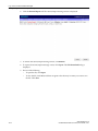
Chapter 19: Working with GuestPortal Administration
About GuestPortals ...................................................................................................................................... 19-1
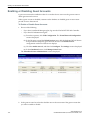
Adding New Guest Accounts ........................................................................................................................ 19-2
Enabling or Disabling Guest Accounts ......................................................................................................... 19-4
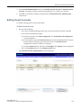
Editing Guest Accounts ................................................................................................................................ 19-5
Removing Guest Accounts ........................................................................................................................... 19-6
Importing and Exporting a Guest File ........................................................................................................... 19-7
Viewing and Printing a GuestPortal Account Ticket ................................................................................... 19-10
Working with the GuestPortal Ticket Page ................................................................................................. 19-12
Working with a Custom GuestPortal Ticket Page ................................................................................ 19-12
Activating a GuestPortal Ticket Page ................................................................................................... 19-13
Uploading a Custom GuestPortal Ticket Page ..................................................................................... 19-13
Deleting a Custom GuestPortal Ticket Page ........................................................................................ 19-13
vi
SCALANCE WLC711
C79000-G8976-C260-03, 07/2012, User Guide, V8.11
Configuring Web Session Timeouts ........................................................................................................... 19-13
Appendix A: Glossary
Networking Terms and Abbreviations .............................................................................................................A-1
Wireless Controller Terms and Abbreviations ..............................................................................................A-15
Appendix B: Default GuestPortal Source Code
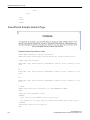
Ticket Page .....................................................................................................................................................B-1
Placeholders Used in the Default GuestPortal Ticket Page .....................................................................B-1
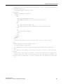
Default GuestPortal Ticket Page Source Code ........................................................................................B-2
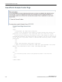
GuestPortal Sample Header Page .................................................................................................................B-4
GuestPortal Sample Footer Page ...................................................................................................................B-6
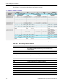
Tables
2-1
2-2
2-3
2-4
3-1
3-2
3-3
3-4
3-5
3-6
3-7
3-8
3-9
3-10
3-11
3-12
3-13
3-14
4-1
5-1
5-2
5-3
5-4
5-5
5-6
5-7
5-8
5-9
5-10
6-1
6-2
6-3
6-4
6-5
6-6
6-7
6-8
6-9
6-10
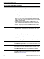
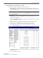
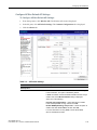
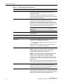
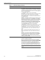
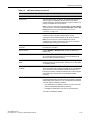
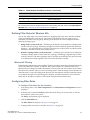
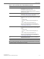
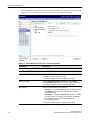
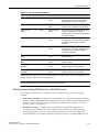
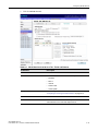
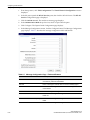
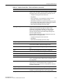
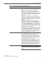
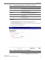
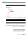
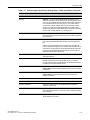
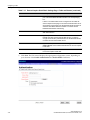
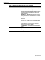
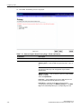
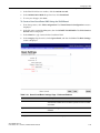
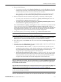
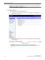
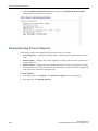
Wireless Assistant Home Screen Headings ....................................................................................... 2-6
Supported Certificate and CA Formats............................................................................................. 2-31
Topologies Page: Certificates Tab Fields and Buttons..................................................................... 2-33
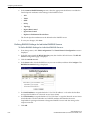
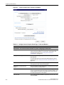
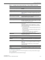
Generate Certificate Signing Request Page - Fields and Buttons.................................................... 2-35
Wireless APs and Antenna Compatibility ........................................................................................... 3-2
CLI Commands to Configure a Static IP Address for a Wireless AP.................................................. 3-9
CLI Commands to Configure a Static IP Address for a Wireless 802.11n AP.................................... 3-9
Siemens Wireless AP LED Status .................................................................................................... 3-13
LEDs Indicating Signal Strength ....................................................................................................... 3-14
LED Operational Modes ................................................................................................................... 3-14
Add Wireless AP window.................................................................................................................. 3-18
AP Properties ................................................................................................................................... 3-21
Radio Properties............................................................................................................................... 3-30
Static Configuration Properties ......................................................................................................... 3-41
AP Default Settings .......................................................................................................................... 3-55
AP Multi-edit Properties .................................................................................................................... 3-68
Maximum Number of Load Balance Groups .................................................................................... 3-70
AP Load Groups ............................................................................................................................... 3-72
Exception Filters page - Fields and Buttons ..................................................................................... 4-13
VLAN & Class of Service Tab - Fields and Buttons............................................................................ 5-2
Filter Types ......................................................................................................................................... 5-3
Non-authenticated Filter Example A ................................................................................................... 5-4
Non-authenticated Filter Example B ................................................................................................... 5-4
Filtering Rules Example A .................................................................................................................. 5-5
Filtering Rules Example B .................................................................................................................. 5-5
Default Filter Example A ..................................................................................................................... 5-6
Default Filter Example B ..................................................................................................................... 5-6
Rules Between Two Wireless Devices ............................................................................................... 5-6
WLC and AP Filters Tabs - Fields and Buttons .................................................................................. 5-9
WLAN Services Configuration Page................................................................................................... 6-4
Advanced WLAN Service Configuration Page ................................................................................... 6-7
WLAN Services Privacy Tab - Fields and Buttons ........................................................................... 6-12
Vendor Specific Attributes ................................................................................................................ 6-15
WLAN Services Auth & Acct Tab - Fields and Buttons .................................................................... 6-19
Configure Internal Captive Portal Page - Fields and Buttons ........................................................... 6-28
Message Configuration Page - Fields and Buttons .......................................................................... 6-30
Captive Portal Editor - Fields and Buttons........................................................................................ 6-32
DSCP Code-Points ........................................................................................................................... 6-35
Service Classes ................................................................................................................................ 6-37
SCALANCE WLC711
User Guide, V8.11, 07/2012, C79000-G8976-C260-03
vii
6-11
6-12
6-13
6-14
7-1
7-2
7-3
7-4
7-5
7-6
7-7
7-8
7-9
7-10
7-11
7-12
7-13
7-14
7-15
7-16
7-17
7-18
7-19
7-20
7-21
7-22
7-23
7-24
8-1
9-1
11-1
16-1
16-2
19-1
A-1
A-2
B-1
Relationship Between Service Class and 802.1D UP ...................................................................... 6-37
Queues ............................................................................................................................................. 6-38
Traffic Prioritization ........................................................................................................................... 6-39
WLAN Services QoS Tab - Fields and Buttons ................................................................................ 6-41
Voice VNS Basic Settings Page - Fields and Buttons ...................................................................... 7-25
Voice VNS Authorization Page - Fields and Buttons ........................................................................ 7-27
Voice VNS DHCP Page - Fields and Buttons................................................................................... 7-29
Voice VNS Radio Assignment Page - Fields and Buttons................................................................ 7-30
Data VNS Basic Settings Page - Fields and Buttons ....................................................................... 7-33
Data VNS Authentication Page - Fields and Buttons ....................................................................... 7-35
Data VNS DHCP Page - Fields and Buttons .................................................................................... 7-37
Data VNS Privacy Page - Fields and Buttons .................................................................................. 7-38
Data VNS Radio Assignment Page - Fields and Buttons ................................................................. 7-40
Captive Portal Basic Settings Page - Fields and Buttons ................................................................. 7-43
Captive Portal Authentication Page - Fields and Buttons ................................................................. 7-45
Captive Portal DHCP Page - Fields and Buttons ............................................................................. 7-46
Captive Portal Privacy Page - Fields and Buttons ............................................................................ 7-48
Captive Portal Radio Assignment Page - Fields and Buttons .......................................................... 7-50
External Captive Portal Basic Settings Page - Fields and Buttons................................................... 7-52
External Captive Portal Authentication Page - Fields and Buttons................................................... 7-55
External Captive Portal DHCP Page - Fields and Buttons ............................................................... 7-56
External Captive Portal Privacy Page - Fields and Buttons.............................................................. 7-58
External Captive Portal Radio Assignment Page - Fields and Buttons ............................................ 7-60
Guest Portal Basic Settings Page - Fields and Buttons ................................................................... 7-63
Guest Portal DHCP Page - Fields and Buttons ................................................................................ 7-65
Guest Portal Privacy Page - Fields and Buttons .............................................................................. 7-67
Guest Portal Radio Assignment Page - Fields and Buttons ............................................................. 7-69
SCALANCE IWLAN Controller Active and Defined VNS Support .................................................... 7-71
General Tab - Fields and Buttons....................................................................................................... 8-3
Configuration Tab - Fields and Buttons .............................................................................................. 9-4
Wireless APs and Their Roles ........................................................................................................ 11-16
AP Inventory Report Columns .......................................................................................................... 16-8
CDR Records and Their Description .............................................................................................. 16-23
Guest Account Import and Export .csv File Values .......................................................................... 19-7
Networking Terms and Abbreviations.................................................................................................A-1
Wireless Controller Terms and Abbreviations ..................................................................................A-15
Default GuestPortal Ticket Page Template Placeholders ..................................................................B-1
Figures
1-1
1-2
1-3
1-4
2-1
2-2
2-3
3-1
3-2
3-3
3-4
5-1
5-2
5-3
viii
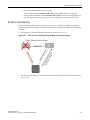
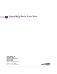
Standard Wireless Network Solution Example ................................................................................... 1-2
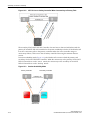
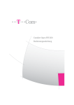
SCALANCE IWLAN Controller Solution ............................................................................................. 1-4
Traffic Flow Diagram .......................................................................................................................... 1-7
VNS as a Binding of Reusable Components .................................................................................... 1-10
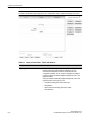
Wireless Assistant Top Menu Bar ...................................................................................................... 2-5
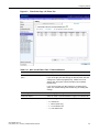
Wireless Assistant Home Screen ....................................................................................................... 2-5
Generate Certificate Signing Request Window ................................................................................ 2-35
SCALANCE W786-2 HPW Outdoor Wireless AP............................................................................... 3-3
MIMO in SCALANCE IWLAN 802.11n AP ......................................................................................... 3-5
SCALANCE IWLAN 802.11n AP’s Baseband .................................................................................... 3-7
Wireless AP Discovery Process ....................................................................................................... 3-10
VLAN & Class of Service Tab............................................................................................................. 5-2
Filter Rules Page - WLC Filters Tab ................................................................................................... 5-8
Filter Rules Page - AP Filters Tab ...................................................................................................... 5-9
SCALANCE WLC711
C79000-G8976-C260-03, 07/2012, User Guide, V8.11
6-1
6-2
6-3
7-1
8-1
10-1
10-2
10-3
10-4
10-5
10-6
10-7
10-8
10-9
10-10
11-1
11-2
11-3
11-4
11-5
11-6
11-7
11-8
11-9
11-10
12-1
12-2
12-3
13-1
16-1
Captive Portal Page Configuration Page for Internal and Guest Splash Modes .............................. 6-27
Captive Portal Page for 802.1x Modes ............................................................................................. 6-27
Captive Portal Page for Guest Portal Mode ..................................................................................... 6-28
VNS Configuration Flow ..................................................................................................................... 7-1
Rate Limiter Example ......................................................................................................................... 8-7
Simple Mesh Configuration .............................................................................................................. 10-2
Wireless Repeater Configuration...................................................................................................... 10-3
Wireless Bridge Configuration .......................................................................................................... 10-3
Examples of Mesh Deployment ........................................................................................................ 10-4
Deployment Example ....................................................................................................................... 10-5
Mesh Setup with a Single Mesh WLAN Service ............................................................................... 10-6
Mesh Setup with Multiple Mesh WLAN Services.............................................................................. 10-7
Parent-Child Relationship Between Wireless APs in Mesh Configuration........................................ 10-9
Multiple-Root Mesh Topology ......................................................................................................... 10-10
Mesh Deployment........................................................................................................................... 10-13
Simple WDS Configuration ............................................................................................................... 11-2
Wireless Repeater Configuration...................................................................................................... 11-3
Wireless Bridge Configuration .......................................................................................................... 11-3
Examples of WDS Deployment ........................................................................................................ 11-4
Deployment Example ....................................................................................................................... 11-5
WDS Setup with a Single WDS WLAN Service................................................................................ 11-6
WDS Setup with Multiple WDS WLAN Services .............................................................................. 11-7
Parent-Child Relationship Between Wireless APs in WDS Configuration ........................................ 11-9
Multiple-root WDS Topology........................................................................................................... 11-10
WDS Deployment ........................................................................................................................... 11-13
AP Fail Over to 2ndary Controller When Primary Goes Down ......................................................... 12-9
AP Fail Over to 2ndary Controller When Connectivity to Primary Fails.......................................... 12-10
Session Availability Mode ............................................................................................................... 12-10
Mobility Domain with Fast Failover and Session Availability Features ............................................. 13-3
Sample .dat File.............................................................................................................................. 16-26
SCALANCE WLC711
User Guide, V8.11, 07/2012, C79000-G8976-C260-03
ix
x
SCALANCE WLC711
C79000-G8976-C260-03, 07/2012, User Guide, V8.11
About This Guide
This guide describes how to install, configure, and manage the SCALANCE WLC711 system. This
guide is also available as an online help system.
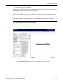
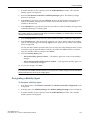
To Access the Online Help System:
1.
In the SCALANCE IWLAN Assistant Top Menu bar, click Help.
2.
The online help system is launched.
Intended Audience
This guide is a reference for system administrators who install and manage the SCALANCE
IWLAN Controller.
Any administrator performing tasks described in this guide must have an account with
administrative privileges.
How to Use This Guide
This preface provides an overview of this guide and a brief summary of each chapter, defines the
conventions used in this document; and instructs how to obtain technical support from Siemens
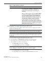
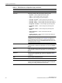
AG. To locate information about various subjects in this guide, refer to the following table.
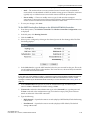
For...
Refer to...
An overview of the product, its features and functionality.
Chapter 1, Overview of the SCALANCE
WLC711 Solution
Information about how to perform the installation, first time
setup and configuration of the SCALANCE IWLAN Controller,
as well as configuring the data ports and defining routing.
Chapter 2, Configuring the SCALANCE
IWLAN Controller
Information on how to install the Wireless AP, how it
discovers and registers with the SCALANCE IWLAN
Controller, and how to view and modify radio configuration.
Chapter 3, Configuring the Wireless AP
An overview of topologies and provides detailed information
about how to configure them.
Chapter 4, Configuring Topologies
An overview of policies and provides detailed information
about how to configure them.
Chapter 5, Configuring Policies
An overview of WLAN services and provides detailed
information about how to configure them.
Chapter 6, Configuring WLAN Services
An overview of Virtual Network Services (VNS), provides
detailed instructions in how to configure a VNS, either using
the Wizards or by manually creating the component parts of a
VNS.
Chapter 7, Configuring a VNS
SCALANCE WLC711
User Guide, V8.11, 07/2012, C79000-G8976-C260-03
xi
About This Guide
Formatting Conventions
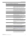
For...
Refer to...
Information about configuring Classes of Service (CoS) which
are a configuration entity containing QoS Marking (802.1p
and ToS/DSCP), Inbound/Outbound Rate Limiting and
Transmit Queue Assignments.
Chapter 8, Configuring Classes of Service
Information about configuring Sites which is a mechanism for
grouping APs and refers to specific Policies, Classes of
Service (CoS) and RADIUS servers that are grouped to form
a single configuration.
Chapter 9, Configuring Sites
An overview of Mesh networks and provides detailed
information about how to create a Mesh network.
Chapter 10, Working with a Mesh Network
An overview of a Wireless Distribution System (WDS)
network configuration and provides detailed information about
how to create a Mesh network.
Chapter 11, Working with a Wireless
Distribution System
Information on how to set up the features that maintain
service availability in the event of a SCALANCE IWLAN
Controller failover.
Chapter 12, Availability and Session
Availability
Information on how to set up the mobility domain that
provides mobility for a wireless device user when the user
roams from one Wireless AP to another in the mobility
domain.
Chapter 13, Configuring Mobility
Information on how to use the SCALANCE WLC711 features
with third-party wireless access points.
Chapter 14, Working with Third-party APs
Information on the security tool that scans for, detects, and
reports on rogue APs.
Chapter 15, Working with the Mitigator
Information on the various reports and displays available in
the SCALANCE WLC711 system.
Chapter 16, Working with Reports and
Statistics
Information on system administration activities, such as
performing Wireless AP client management, defining
management users, configuring the network time, and
configuring Web session timeouts.
Chapter 17, Performing System
Administration
Information on how to view and interpret the logs, traces,
audits and DHCP messages.
Chapter 18, Logs, Traces, Audits and
DHCP Messages
Information on how to configure GuestPortal accounts using
the SCALANCE WLC711.
Chapter 19, Working with GuestPortal
Administration
A list of terms and definitions for the SCALANCE IWLAN
Controller and the Wireless AP as well as standard industry
terms used in this guide.
Appendix A, Glossary
The default GuestPortal ticket page source code.
Appendix B, Default GuestPortal Source
Code
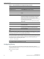
Formatting Conventions
The SCALANCE WLC711 documentation uses the following formatting conventions to make it
easier to find information and follow procedures:
•
xii
Bold text is used to identify components of the management interface, such as menu items
and section of pages, as well as the names of buttons and text boxes.
SCALANCE WLC711
C79000-G8976-C260-03, 07/2012, User Guide, V8.11
About This Guide
Additional Documentation
For example: Click Logout.
•
Monospace font is used in code examples and to indicate text that you type.
For example: Type https://<wlc-address>[:mgmt-port]
Additional Documentation
SCALANCE IWLAN Controller documentation is available at:
www.siemens.com/automation/service&support
SCALANCE WLC711
User Guide, V8.11, 07/2012, C79000-G8976-C260-03
xiii
About This Guide
Additional Documentation
xiv
SCALANCE WLC711
C79000-G8976-C260-03, 07/2012, User Guide, V8.11
1
Overview of the SCALANCE WLC711 Solution
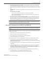
This chapter describes SCALANCE WLC711 concepts, including:
For information about...
Refer to page...
Introduction
1-1
Conventional Wireless LANs
1-2
Elements of the SCALANCE WLC711 Solution
1-3
SCALANCE WLC711 and Your Network
1-5
Introduction
The next generation of Siemens wireless networking devices provides a truly scalable WLAN
solution. SCALANCE IWLAN Controller Access Points (Wireless APs) are fit access points
controlled through a sophisticated network device, the SCALANCE IWLAN Controller. This
solution provides the security and manageability required for huge industrial wireless networks.
The SCALANCE IWLAN Controller provides a secure, highly scalable, cost-effective solution
based on the IEEE 802.11 standard.
This chapter provides an overview of the fundamental principles of the SCALANCE IWLAN
Controller.
The SCALANCE IWLAN Controller
The SCALANCE IWLAN Controller is a network device designed to integrate with an existing
wired Local Area Network (LAN). The SCALANCE IWLAN Controller provides centralized
management, network access, and routing to wireless devices that use Wireless APs to access the
network. It can also be configured to handle data traffic from third-party access points.
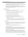
The SCALANCE IWLAN Controller provides the following functionality:
•
Controls and configures Wireless APs, providing centralized management
•
Authenticates wireless devices that contact a Wireless AP
•
Assigns each wireless device to a VNS when it connects
•
Routes traffic from wireless devices, using VNS, to the wired network
•
Applies filtering policies to the wireless device session
•
Provides session logging and accounting capability
SCALANCE WLC711
User Guide, V8.11, 07/2012, C79000-G8976-C260-03
1-1
Overview of the SCALANCE WLC711 Solution
Conventional Wireless LANs
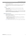
Conventional Wireless LANs
Wireless communication between multiple computers requires that each computer be equipped
with a receiver/transmitter—a WLAN Network Interface Card (NIC)—capable of exchanging
digital information over a common radio frequency. This is called an ad hoc network
configuration. An ad hoc network configuration allows wireless devices to communicate together.
This setup is defined as an independent basic service set (IBSS).
An alternative to the ad hoc configuration is the use of an access point. This may be a dedicated
hardware bridge or a computer running special software. Computers and other wireless devices
communicate with each other through this access point. The 802.11 standard defines access point
communications as devices that allow wireless devices to communicate with a distribution
system. This setup is defined as a basic service set (BSS) or infrastructure network.
To allow the wireless devices to communicate with computers on a wired network, the access
points must be connected to the wired network providing access to the networked computers.
This topology is called bridging. With bridging, security and management scalability is often a
concern.
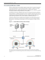
Figure 1-1
Standard Wireless Network Solution Example
RADIUS
Authentication
Server
DHCP Server
Ethernet
Router/Switch
Wireless AP
Wireless AP
Ethernet
Wireless Devices
The wireless devices and the wired networks communicate with each other using standard
networking protocols and addressing schemes. Most commonly, Internet Protocol (IP) addressing
is used.
1-2
SCALANCE WLC711
C79000-G8976-C260-03, 07/2012, User Guide, V8.11
Overview of the SCALANCE WLC711 Solution
Elements of the SCALANCE WLC711 Solution
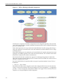
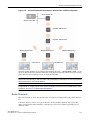
Elements of the SCALANCE WLC711 Solution
The SCALANCE WLC711 solution consists of two devices:
•
SCALANCE IWLAN Controller
•
IWLAN Controller Access Points (Wireless APs)
This architecture allows a single SCALANCE IWLAN Controller to control many Wireless APs,
making the administration and management of large networks much easier.
There can be several SCALANCE IWLAN Controllers in the network, each with a set of registered
Wireless APs. The SCALANCE IWLAN Controllers can also act as backups to each other,
providing stable network availability.
In addition to the SCALANCE IWLAN Controllers and Wireless APs, the solution requires three
other components, all of which are standard for enterprise and service provider networks:
•
RADIUS Server (Remote Access Dial-In User Service) or other authentication server
•
DHCP Server (Dynamic Host Configuration Protocol). If you do not have a DHCP Server on
your network, you can enable the local DHCP Server on the SCALANCE IWLAN Controller.
The local DHCP Server is useful as a general purpose DHCP Server for small subnets. For
more information, see Step 11 of “Setting Up the Data Ports” on page 2-14.
•
SLP (Service Location Protocol)
SCALANCE WLC711
User Guide, V8.11, 07/2012, C79000-G8976-C260-03
1-3
Overview of the SCALANCE WLC711 Solution
Elements of the SCALANCE WLC711 Solution
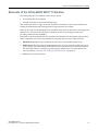
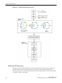
Figure 1-2
SCALANCE IWLAN Controller Solution
RADIUS
Authentication
Server
DHCP Server
Wireless
Controller
Ethernet
Router/Switch
Ethernet
Wireless AP
Wireless AP
Wireless Devices
As illustrated in Figure 1-2, the SCALANCE IWLAN Controller appears to the existing network as
if it were an access point, but in fact one SCALANCE IWLAN Controller controls many Wireless
APs. The SCALANCE IWLAN Controller has built-in capabilities to recognize and manage the
Wireless APs. The SCALANCE IWLAN Controller:
•
Activates the Wireless APs
•
Enables Wireless APs to receive wireless traffic from wireless devices
•
Processes the data traffic from the Wireless APs
•
Forwards or routes the processed data traffic out to the network
•
Authenticates requests and applies access policies
Simplifying the Wireless APs makes them cost-effective, easy to manage, and easy to deploy.
Putting control on an intelligent centralized SCALANCE IWLAN Controller enables:
1-4
•
Centralized configuration, management, reporting, and maintenance
•
High security
•
Flexibility to suit enterprise
•
Scalable and resilient deployments with a few SCALANCE IWLAN Controllers controlling
hundreds of Wireless APs
SCALANCE WLC711
C79000-G8976-C260-03, 07/2012, User Guide, V8.11
Overview of the SCALANCE WLC711 Solution
SCALANCE WLC711 and Your Network
The SCALANCE IWLAN system:
•
Scales up to Enterprise capacity — SCALANCE IWLAN Controllers are scalable:
–
WLC711 — Up to 32 APs
In turn, each Wireless AP can handle up to 254 wireless devices, with each radio supporting a
maximum of 127. With additional SCALANCE IWLAN Controllers, the number of wireless
devices the solution can support can reach into the thousands.
•
Integrates with existing network — A SCALANCE IWLAN Controller can be added to an
existing enterprise network as a new network device, greatly enhancing its capability without
interfering with existing functionality. Integration of the SCALANCE IWLAN Controllers and
Wireless APs does not require any re-configuration of the existing infrastructure (for example,
VLANs).
•
Offers centralized management and control — An administrator accesses the SCALANCE
IWLAN Controller in its centralized location to monitor and administer the entire wireless
network. From the SCALANCE IWLAN Controller the administrator can recognize,
configure, and manage the Wireless APs and distribute new software releases.
•
Provides easy deployment of Wireless APs — The initial configuration of the Wireless APs on
the centralized SCALANCE IWLAN Controller can be done with an automatic “discovery”
technique.
•
Provides security via user authentication — Uses existing authentication (AAA) servers to
authenticate and authorize users.
•
Provides security via filters and privileges — Uses virtual networking techniques to create
separate virtual networks with defined authentication and billing services, access policies, and
privileges.
•
Supports seamless mobility and roaming — Supports seamless roaming of a wireless device
from one Wireless AP to another on the same SCALANCE IWLAN Controller or on a
different SCALANCE IWLAN Controller.
•
Integrates third-party access points — Uses a combination of network routing and
authentication techniques.
•
Prevents rogue devices — Unauthorized access points are detected and identified as either
harmless or dangerous rogue APs.
•
Provides accounting services — Logs wireless user sessions, user group activity, and other
activity reporting, enabling the generation of consolidated billing records.
•
Offers troubleshooting capability — Logs system and session activity and provides reports
to aid in troubleshooting analysis.
•
Offers dynamic RF management — Automatically selects channels and adjusts Radio
Frequency (RF) signal propagation and power levels without user intervention.
SCALANCE WLC711 and Your Network
This section is a summary of the components of the SCALANCE WLC711 solution on your
enterprise network. The following are described in detail in this guide, unless otherwise stated:
•
SCALANCE IWLAN Controller — A network device that provides centralized control over
all access points and manages the network assignment of wireless device clients associating
through access points.
SCALANCE WLC711
User Guide, V8.11, 07/2012, C79000-G8976-C260-03
1-5
Overview of the SCALANCE WLC711 Solution
SCALANCE WLC711 and Your Network
•
IWLAN Controller Access Point (Wireless AP) — A wireless LAN fit access point that
communicates with a SCALANCE IWLAN Controller.
•
RADIUS Server (Remote Access Dial-In User Service) (RFC2865), or other authentication
server — An authentication server that assigns and manages ID and Password protection
throughout the network. Used for authentication of the wireless users in either 802.1x or
Captive Portal security modes. The RADIUS Server system can be set up for certain standard
attributes, such as filter ID, and for the Vendor Specific Attributes (VSAs). In addition,
RADIUS Disconnect (RFC3576) which permits dynamic adjustment of user policy (user
disconnect) is supported.
•
DHCP Server (Dynamic Host Configuration Protocol) (RFC2131) — A server that assigns
dynamically IP addresses, gateways, and subnet masks. IP address assignment for clients can
be done by the DHCP server internal to the SCALANCE IWLAN Controller, or by existing
servers using DHCP relay. It is also used by the Wireless APs to discover the location of the
SCALANCE IWLAN Controller during the initial registration process using Options 43, 60,
and Option 78. Options 43 and 60 specify the vendor class identifier (VCI) and vendor specific
information. Option 78 specifies the location of one or more SLP Directory Agents. For SLP,
DHCP should have Option 78 enabled.
•
Service Location Protocol (SLP) (SLP RFC2608) — Client applications are User Agents and
services that are advertised by a Service Agent. In larger installations, a Directory Agent
collects information from Service Agents and creates a central repository. The Siemens
solution relies on registering “Siemens” as an SLP Service Agent.
•
Domain Name Server (DNS) — A server used as an alternate mechanism (if present on the
enterprise network) for the automatic discovery process. SCALANCE IWLAN Controller,
Access Points and Convergence Software relies on the DNS for Layer 3 deployments and for
static configuration of Wireless APs. The controller can be registered in DNS, to provide DNS
assisted AP discovery. In addition, DNS can also be used for resolving RADIUS server
hostnames.
•
Web Authentication Server — A server that can be used for external Captive Portal and
external authentication. The SCALANCE IWLAN Controller has an internal Captive portal
presentation page, which allows Web authentication (Web redirection) to take place without
the need for an external Captive Portal server.
•
RADIUS Accounting Server (Remote Access Dial-In User Service) (RFC2866) — A server that
is required if RADIUS Accounting is enabled.
•
Simple Network Management Protocol (SNMP) — A Manager Server that is required if
forwarding SNMP messages is enabled.
•
Network infrastructure — The Ethernet switches and routers must be configured to allow
routing between the various services noted above. Routing must also be enabled between
multiple SCALANCE IWLAN Controllers for the following features to operate successfully:
–
Availability
–
Mobility
–
Mitigator for detection of rogue access points
Some features also require the definition of static routes.
1-6
•
Web Browser — A browser provides access to the SCALANCE IWLAN Controller
Management user interface to configure the SCALANCE WLC711.
•
SSH Enabled Device — A device that supports Secure Shell (SSH) is used for remote (IP) shell
access to the system.
SCALANCE WLC711
C79000-G8976-C260-03, 07/2012, User Guide, V8.11
Overview of the SCALANCE WLC711 Solution
SCALANCE WLC711 and Your Network
•
Zone Integrity — The Zone integrity server enhances network security by ensuring clients
accessing your network are compliant with your security policies before gaining access. Zone
Integrity Release 5 is supported.
Network Traffic Flow
Figure 1-3 illustrates a simple configuration with a single SCALANCE IWLAN Controller and two
Wireless APs, each supporting a wireless device. A RADIUS server on the network provides
authentication, and a DHCP server is used by the Wireless APs to discover the location of the
SCALANCE IWLAN Controller during the initial registration process. Network inter-connectivity
is provided by the infrastructure routing and switching devices.
Figure 1-3
Traffic Flow Diagram
Packet transmission
RADIUS
Authentication
Server
DHCP
Server
External
CP Server
External Web
Authentication
Server
Control and Routing
>WLC authenticates wireless user
>WLC forwards IP packet to wired
network
Tunnelling
>AP sends data traffic to WLC
through UDP tunnel called
WASSP
>WLC controls Wireless AP
through WASSP tunnel
>Using WASSP tunnels, WLC
allows wireless clients to roam to
Wireless APs on different WLCs
Wireless
Controller
Router/Switch
802.11 packet transmission
802.11 beacon and probe,
wireless device associates
with a Wireless AP
by its SSID
Wireless APs
Wireless Devices
Each wireless device sends IP packets in the 802.11 standard to the Wireless AP. The Wireless AP
uses a UDP (User Datagram Protocol) based tunnelling protocol. In tunneled mode of operation, it
SCALANCE WLC711
User Guide, V8.11, 07/2012, C79000-G8976-C260-03
1-7
Overview of the SCALANCE WLC711 Solution
SCALANCE WLC711 and Your Network
encapsulates the packets and forwards them to the SCALANCE IWLAN Controller. The
SCALANCE IWLAN Controller decapsulates the packets and routes these to destinations on the
network. In a typical configuration, access points can be configured to locally bridge traffic (to a
configured VLAN) directly at their network point of attachment.
The SCALANCE IWLAN Controller functions like a standard L3 router or L2 switch. It is
configured to route the network traffic associated with wireless connected users. The SCALANCE
IWLAN Controller can also be configured to simply forward traffic to a default or static route if
dynamic routing is not preferred or available.
Network Security
The SCALANCE WLC711 system provides features and functionality to control network access.
These are based on standard wireless network security practices.
Current wireless network security methods provide protection. These methods include:
•
Shared Key authentication that relies on Wired Equivalent Privacy (WEP) keys
•
Open System that relies on Service Set Identifiers (SSIDs)
•
802.1x that is compliant with Wi-Fi Protected Access (WPA)
•
Captive Portal based on Secure Sockets Layer (SSL) protocol
The SCALANCE WLC711 system provides the centralized mechanism by which the
corresponding security parameters are configured for a group of users.
•
Wired Equivalent Privacy (WEP) is a security protocol for wireless local area networks
defined in the 802.11b standard
•
Wi-Fi Protected Access version 1 (WPA1™) with Temporal Key Integrity Protocol (TKIP)
•
Wi-Fi Protected Access version 2 (WPA2™) with Advanced Encryption Standard (AES) and
Counter Mode with Cipher Block Chaining Message Authentication Code (CCMP)
Authentication
The SCALANCE IWLAN Controller relies on a RADIUS server, or authentication server, on the
enterprise network to provide the authentication information (whether the user is to be allowed or
denied access to the network). A RADIUS client is implemented to interact with infrastructure
RADIUS servers.
The SCALANCE IWLAN Controller provides authentication using:
•
Captive Portal — a browser-based mechanism that forces users to a Web page
•
RADIUS (using IEEE 802.1x)
The 802.1x mechanism is a standard for authentication developed within the 802.11 standard. This
mechanism is implemented at the wireless port, blocking all data traffic between the wireless
device and the network until authentication is complete. Authentication by 802.1x standard uses
Extensible Authentication Protocol (EAP) for the message exchange between the SCALANCE
IWLAN Controller and the RADIUS server.
When 802.1x is used for authentication, the SCALANCE IWLAN Controller provides the
capability to dynamically assign per-wireless-device WEP keys (called per session WEP keys in
802.11). In the case of WPA, the SCALANCE IWLAN Controller is not involved in key assignment.
Instead, the controller is involved in the information exchange between RADIUS server and the
user’s wireless device to negotiate the appropriate set of keys. With WPA2 the material exchange
1-8
SCALANCE WLC711
C79000-G8976-C260-03, 07/2012, User Guide, V8.11
Overview of the SCALANCE WLC711 Solution
SCALANCE WLC711 and Your Network
produces a Pairwise Master Key which is used by the AP and the user to derive their temporal
keys. (The keys change over time.)
The SCALANCE WLC711 solution provide a RADIUS redundancy feature that enables you to
define a failover RADIUS server in the event that the active RADIUS server becomes
unresponsive.
Privacy
Privacy is a mechanism that protects data over wireless and wired networks, usually by
encryption techniques.
SCALANCE WLC711 supports the Wired Equivalent Privacy (WEP) standard common to
conventional access points.
It also provides Wi-Fi Protected Access version 1 (WPA v.1) encryption, based on Pairwise Master
Key (PMK) and Temporal Key Integrity Protocol (TKIP). The most secure encryption mechanism
is WPA version 2, using Advanced Encryption Standard (AES).
Virtual Network Services
Virtual Network Services (VNS) provide a versatile method of mapping wireless networks to the
topology of an existing wired network.
A VNS is the binding of reusable components:
•
WLAN Service components that define the radio attributes, privacy and authentication
settings, and QoS attributes of the VNS
•
Policy components that define the topology (typically a VLAN), filter rules, and Class of
Service applied to the traffic of a station.
Figure 1-4 illustrates the transition of the concept of a VNS to a binding of reusable components.
SCALANCE WLC711
User Guide, V8.11, 07/2012, C79000-G8976-C260-03
1-9
Overview of the SCALANCE WLC711 Solution
SCALANCE WLC711 and Your Network
Figure 1-4
VNS as a Binding of Reusable Components
WLAN Service components and Policy components can be configured separately and associated
with a VNS when the VNS is created or modified. Alternatively, they can be configured during the
process of creating a VNS.
When VNS components are set up on the SCALANCE IWLAN Controller, among other things, a
range of IP addresses is set aside for the SCALANCE IWLAN Controller’s DHCP server to assign
to wireless devices.
If the OSPF routing protocol is enabled, the SCALANCE IWLAN Controller advertises the routed
topologies as reachable segments to the wired network infrastructure. The controller routes traffic
between the wireless devices and the wired network.
The SCALANCE IWLAN Controller also supports VLAN-bridged assignment for VNSs. This
allows the controller to directly bridge the set of wireless devices associated with a WLAN service
directly to a specified core VLAN.
Each SCALANCE IWLAN Controller model can support a specified number of active VNSs, as
listed below:
•
WLC711 — Up to 8 VNSs
The Wireless AP radios can be assigned to each of the configured WLAN services and, therefore,
VNSs in a system. Each Wireless AP can be the subject of 16 service assignments — 8 assignments
per radio — which corresponds to the number of SSIDs it can support. Once a radio has all 8 slots
assigned, it is no longer eligible for further assignment.
1-10
SCALANCE WLC711
C79000-G8976-C260-03, 07/2012, User Guide, V8.11
Overview of the SCALANCE WLC711 Solution
SCALANCE WLC711 and Your Network
VNS Components
The distinct constituent high-level configurable umbrella elements of a VNS are:
•
Topology
•
Policy
•
Classes of Service
•
WLAN Service
Topology
Topologies represent the networks with which the SCALANCE IWLAN Controller and its APs
interact. The main configurable attributes of a topology are:
•
Name - a string of alphanumeric characters designated by the administrator.
•
VLAN ID - the VLAN identifier as specified in the IEEE 802.1Q definition.
•
VLAN tagging options.
•
Port of presence for the topology on the SCALANCE IWLAN Controller. (This attribute is not
required for Routed and Bridged at AP topologies.)
•
Interface. This attribute is the IP (L3) address assigned to the SCALANCE IWLAN Controller
on the network described by the topology. (Optional.)
•
Type. This attribute describes how traffic is forwarded on the topology. Options are:
–
“Physical” - the topology is the native topology of a data plane and it represents the actual
Ethernet ports
–
“Management” - the native topology of the SCALANCE IWLAN Controller management
port
–
“Routed” - the controller is the routing gateway for the routed topology.
–
“Bridged at Controller” - the user traffic is bridged (in the L2 sense) between wireless
clients and the core network infrastructure.
–
“Bridged at AP” - the user traffic is bridged locally at the AP without being redirected to
the SCALANCE IWLAN Controller.
•
Exception Filters. Specifies which traffic has access to the SCALANCE IWLAN Controller
from the wireless clients or the infrastructure network.
•
Certificates.
•
Multicast filters. Defines the multicast groups that are allowed on a specific topology segment.
Policy
A Policy is a collection of attributes and rules that determine actions taken user traffic accesses the
wired network through the WLAN service (associated to the WLAN Service's SSID). Depending
upon its type, a VNS can have between one and three Authorization Policies associated with it:
1.
Default non-authorized policy — This is a mandatory policy that covers all traffic from
stations that have not authenticated. At the administrator's discretion the default nonauthorized policy can be applied to the traffic of authenticated stations as well.
SCALANCE WLC711
User Guide, V8.11, 07/2012, C79000-G8976-C260-03
1-11
Overview of the SCALANCE WLC711 Solution
SCALANCE WLC711 and Your Network
2.
Default authorized policy — This is a mandatory policy that applies to the traffic of
authenticated stations for which no other policy was explicitly specified. It can be the same as
the default non-authorized policy.
3.
Third party AP policy — This policy applies to the list of MAC addresses corresponding to the
wired interfaces of third party APs specifically defined by the administrator to be providing
the RF access as an AP WLAN Service. This policy is only relevant when applied to third
party AP WLAN Services.
Classes of Service
In general, Class of Service (CoS) refers to a set of attributes that define the importance of a frame
while it is forwarded through the network relative to other packets, and to the maximum
throughput per time unit that a station or port assigned to a specific policy is permitted. The CoS
defines actions to be taken when rate limits are exceeded.
All incoming packets may follow these steps to determine a CoS:
•
Classification - identifies the first matching rule that defines a CoS.
•
Marking - modifies the L2 802.1p and/or L3 ToS based on CoS definition.
•
Rate limiting (drop) is set.
The system limit for the number of CoS profiles on a controller is identical to the number of
policies. For example, the maximum number of CoS profiles on a WLC711 is 64.
WLAN Services
A WLAN Service represents all the RF, authentication and QoS attributes of a wireless access
service offered by the SCALANCE IWLAN Controller and its APs. A WLAN Service can be one of
the following types:
1-12
•
Standard — A conventional service. Only APs running SCALANCE IWLAN software can be
part of this WLAN Service. This type of service can be used as a Bridged at Controller,
Bridged at AP, or Routed Topology. This type of service provides access for mobile stations.
Policies can be associated with this type of WLAN service to create a VNS.
•
Third Party AP — A Wireless Service offered by third party APs. This type of service provides
access for mobile stations. Policies can be assigned to this type of WLAN service to create a
VNS.
•
Dynamic Mesh and WDS (Static Mesh)— This is to configure a group of APs organized into a
hierarchy for purposes of providing a Wireless Distribution Service. This type of service is in
essence a wireless trunking service rather than a service that provides access for stations. As
such, this service cannot have policies attached to it.
•
Remote — A service that resides on the edge (foreign) SCALANCE IWLAN Controller.
Pairing a remote service with a remoteable service on the designated home SCALANCE
IWLAN Controller allows you to provision centralized WLAN Services in the mobility
domain. This is known as centralized mobility.
SCALANCE WLC711
C79000-G8976-C260-03, 07/2012, User Guide, V8.11
Overview of the SCALANCE WLC711 Solution
SCALANCE WLC711 and Your Network
Routing
Routing can be used on the SCALANCE IWLAN Controller to support the VNS definitions.
Through the user interface you can configure routing on the SCALANCE IWLAN Controller to
use one of the following routing techniques:
•
Static routes — Use static routes to set the default route of a SCALANCE IWLAN Controller
so that legitimate wireless device traffic can be forwarded to the default gateway.
•
Open Shortest Path First (OSPF, version 2) (RFC2328) — Use OSPF to allow the SCALANCE
IWLAN Controller to participate in dynamic route selection. OSPF is a protocol designed for
medium and large IP networks with the ability to segment routes into different areas by
routing information summarization and propagation. Static Route definition and OSPF
dynamic learning can be combined, and the precedence of a static route definition over
dynamic rules can be configured by selecting or clearing the Override dynamic routes option
checkbox.
•
Next-hop routing — Use next-hop routing to specify a unique gateway to which traffic on a
VNS is forwarded. Defining a next-hop for a VNS forces all the traffic in the VNS to be
forwarded to the indicated network device, bypassing any routing definitions of the
controller's route table.
Mobility and Roaming
In typical simple configurations, APs are set up as bridges that bridge wireless traffic to the local
subnet. In bridging configurations, the user obtains an IP address from the same subnet as the AP,
assuming no VLAN trunking functionality. If the user roams between APs on the same subnet, it
is able to keep using the same IP address. However, if the user roams to another AP outside of that
subnet, its IP address is no longer valid. The user's client device must recognize that the IP address
it has is no longer valid and re-negotiate a new one on the new subnet. This mechanism does not
mandate any action on the user. The recovery procedure is entirely client device dependent. Some
clients automatically attempt to obtain a new address on roam (which affects roaming latency),
while others will hold on to their IP address. This loss of IP address continuity seriously affects the
client's experience in the network, because in some cases it can take minutes for a new address to
be negotiated.
The SCALANCE WLC711 solution centralizes the user's network point of presence, therefore
abstracting and decoupling the user's IP address assignment from that of the APs location subnet.
That means that the user is able to roam across any AP without losing its own IP address,
regardless of the subnet on which the serving APs are deployed.
In addition, a SCALANCE IWLAN Controller can learn about other SCALANCE IWLAN
Controllers on the network and then exchange client session information. This enables a wireless
device user to roam seamlessly between different Wireless APs on different SCALANCE IWLAN
Controllers.
Network Availability
The SCALANCE WLC711 solution provides availability against Wireless AP outages, controller
outages, and even network outages. The SCALANCE IWLAN Controller in a VLAN bridged
topology can potentially allow the user to retain the IP address in a failover scenario, if the VNS/
VLAN is common to both controllers. For example, availability is provided by defining a paired
controller configuration by which each peer can act as the backup controller for the other's APs.
APs in one controller are allowed to fail over and register with the alternate controller.
SCALANCE WLC711
User Guide, V8.11, 07/2012, C79000-G8976-C260-03
1-13
Overview of the SCALANCE WLC711 Solution
SCALANCE WLC711 and Your Network
If the primary SCALANCE IWLAN Controller fails, all of its associated Wireless APs can
automatically switch over to another SCALANCE IWLAN Controller that has been defined as the
secondary or backup controller. If an AP reboots, the primary SCALANCE IWLAN Controller is
restored if it is active. However, active APs will continue to be connected to the backup controller
until the administrator releases them back to the primary home controller.
Quality of Service (QoS)
SCALANCE WLC711 solution provides advanced Quality of Service (QoS) management to
provide better network traffic flow. Such techniques include:
•
WMM (Wi-Fi Multimedia) — WMM is enabled per WLAN service. The SCALANCE IWLAN
Controller provides centralized management of the AP features. For devices with WMM
enabled, the standard provides multimedia enhancements for audio, video, and voice
applications. WMM shortens the time between transmitting packets for higher priority traffic.
WMM is part of the 802.11e standard for QoS. In the context of the SCALANCE IWLAN
Solution, the ToS/DSCP field is used for classification and proper class of service mapping,
output queue selection, and priority tagging.
•
IP ToS (Type of Service) or DSCP (Diffserv Codepoint) — The ToS/DSCP field in the IP
header of a frame indicates the priority and class of service for each frame. Adaptive QoS
ensures correct priority handling of client payload packets tunneled between the controller
and AP by copying the IP ToS/DSCP setting from client packet to the header of the
encapsulating tunnel packet.
•
Rate Control — Rate Control for user traffic can also be considered as an aspect of QoS. As
part of Policy definition, the user can specify (default) policy that includes Ingress and Egress
rate control. Ingress rate control applies to traffic generated by wireless clients and Egress rate
control applies to traffic targeting specific wireless clients. The bit-rates can be configured as
part of globally available profiles which can be used by any particular configuration. A global
default is also defined.
Quality of Service (QoS) management is also provided by:
1-14
•
Assigning high priority to a WLAN service
•
Adaptive QoS (automatic and all time feature)
•
Support for legacy devices that use SpectraLink Voice Protocol (SVP) for prioritizing voice
traffic (configurable)
SCALANCE WLC711
C79000-G8976-C260-03, 07/2012, User Guide, V8.11
2
Configuring the SCALANCE IWLAN Controller
This chapter describes the steps involved in the initial configuration and setup, of the SCALANCE
IWLAN Controller, including:
For information about...
Refer to page...
System Configuration Overview
2-1
Logging on to the SCALANCE IWLAN Controller
2-4
Wireless Assistant Home Screen
2-4
Working with the Basic Installation Wizard
2-7
Configuring the SCALANCE IWLAN Controller for the First Time
2-12
Using an AeroScout/Ekahau Location-based Solution
2-54
Additional Ongoing Operations of the System
2-58
System Configuration Overview
The following section provides a high-level overview of the steps involved in the initial
configuration of your system:
1.
Before you begin the configuration process, research the type of WLAN deployment that is
required. For example, topology and VLAN IDs, SSIDs, security requirements, and filter
policies.
2.
Prepare the network servers. Ensure that the external servers, such as DHCP and RADIUS
servers (if applicable) are available and appropriately configured.
3.
Install the SCALANCE IWLAN Controller. For more information, see the documentation for
your SCALANCE IWLAN Controller.
4.
Perform the first time setup of the SCALANCE IWLAN Controller on the physical network,
which includes configuring the IP addresses of the interfaces on the SCALANCE IWLAN
Controller.
–
Create a new physical topology and provide the IP address to be the relevant subnet point
of attachment to the existing network.
–
To manage the SCALANCE IWLAN Controller through the interface configured above,
select the Mgmt checkbox on the Interfaces tab.
–
Configure the data port interfaces to be on separate VLANs, matching the VLANs
configured in Step 3 above. Ensure also that the tagged vs. untagged state is consistent
with the switch port configuration.
SCALANCE WLC711
User Guide, V8.11, 07/2012, C79000-G8976-C260-03
2-1
Configuring the SCALANCE IWLAN Controller
–
Configure the time zone. Because changing the time zone requires restarting the
SCALANCE IWLAN Controller, Siemens recommends that you configure the time zone
during the initial installation and configuration of the SCALANCE IWLAN Controller to
avoid network interruptions. For more information, see “Configuring Network Time” on
page 2-49.
–
Apply an activation key file. If an activation key is not applied, the SCALANCE IWLAN
Controller functions with some features enabled in demonstration mode. Not all features
are enabled in demonstration mode. For example, mobility is not enabled and cannot be
used.
NOTICE
Whenever the licensed region changes on the SCALANCE IWLAN Controller, all Wireless APs are changed
to Auto Channel Select to prevent possible infractions to local RF regulatory requirements. If this occurs, all
manually configured radio channel settings will be lost.
5.
Configure the SCALANCE IWLAN Controller for remote access:
–
Set up an administration station (laptop) on subnet 192.168.10.0/24. By default, the
SCALANCE IWLAN Controller's Management interface is configured with the static IP
address 192.168.10.1.
–
Configure the SCALANCE IWLAN Controller’s management interface.
–
Configure the data interfaces.
–
Set up the SCALANCE IWLAN Controller on the network by configuring the physical
data ports.
–
Configure the routing table.
–
Configure static routes or OSPF parameters, if appropriate to the network.
For more information, see “Configuring the SCALANCE IWLAN Controller for the First
Time” on page 2-12.
6.
Configure the traffic topologies your network must support. Topologies represent the
Controller’s points of network attachment, and therefore VLANs and port assignments need
to be coordinated with the corresponding network switch ports. For more information, see
“Configuring a Basic Data Port Topology” on page 4-4.
7.
Configure policies. Policies are typically bound to topologies. Policy application assigns user
traffic to the corresponding network point.
–
Policies define user access rights (filtering or ACL)
–
Polices reference user's rate control profile.
For more information, see “Configuring Policies” on page 5-1.
8.
Configure WLAN services.
–
Define SSID and privacy settings for the wireless link.
–
Select the set of APs/Radios on which the service is present.
–
Configure the method of credential authentication for wireless users (None, Internal CP,
External CP, GuestPortal, 802.1x[EAP])
For more information, see “Configuring WLAN Services” on page 6-1.
9.
2-2
Create the VNSs.
SCALANCE WLC711
C79000-G8976-C260-03, 07/2012, User Guide, V8.11
Configuring the SCALANCE IWLAN Controller
A VNS binds a WLAN Service to a Policy that will be used for default assignment upon a
user’s network attachment.
You can create topologies, policies, and WLAN services first, before configuring a VNS, or you
can select one of the wizards (such as the VNS wizard), or you can simply select to create new
VNS.
The VNS page then allows for in-place creation and definition of any dependency it may
require, such as:
–
Creating a new WLAN Service
–
Creating a new policy
–
Creating a new class of service (within a policy)
–
Creating a new topology (within a policy)
–
Creating new rate controls, and other Class of Service parameters
The default shipping configuration does not ship any pre-configured WLAN Services, VNSs,
or Policies.
10. Install, register, and assign APs to the VNS.
–
Confirm the latest firmware version is loaded. For more information, see “Performing
Wireless AP Software Maintenance” on page 3-76.
–
Deploy Wireless APs to their corresponding network locations.
–
If applicable, configure a default AP template for common radio assignment, whereby
APs automatically receive complete configuration. For typical deployments where all APs
are to have the same configuration, this feature will expedite deployment, as an AP will
automatically receive full configuration (including VNS-related assignments) upon initial
registration with the SCALANCE IWLAN Controller. If applicable, modify the properties
or settings of the Wireless APs. For more information, see Chapter 3, Configuring the
Wireless AP.
–
Connect the Wireless APs to the SCALANCE IWLAN Controller.
–
Once the Wireless APs are powered on, they automatically begin the Discovery process of
the SCALANCE IWLAN Controller, based on factors that include:
-
Their Registration mode (on the Wireless AP Registration screen)
-
The enterprise network services that will support the discovery process
SCALANCE WLC711
User Guide, V8.11, 07/2012, C79000-G8976-C260-03
2-3
Configuring the SCALANCE IWLAN Controller
Logging on to the SCALANCE IWLAN Controller
Logging on to the SCALANCE IWLAN Controller
1.
Launch your Web browser (Internet Explorer version 6.0 or higher, or FireFox).
See the V8.01 release notes for the supported Web browsers.
2.
In the browser address bar, type the following, using the IP address of your controller:
https://192.168.10.1:5825
This launches the Wireless Assistant. The login screen is displayed.
3.
In the User Name box, type your user name.
4.
In the Password box, type your password.
Note:
The SCALANCE IWLAN Controller default user name is admin. The default password is abc123.
5.
Click Login. The Wireless Assistant Home Screen is displayed.
Wireless Assistant Home Screen
The Wireless Assistant Home Screen provides real-time status information on the current state of
the wireless network. Information is grouped under multiple functional areas (Network Status,
Admin sessions, and so on) and provides a graphical representation of active AP information
(such as the number of wired packets, stations, and total APs).
The top menu bar displays across each page within the Wireless Assistant. Using the top menu
bar, you can access Wireless Controllers, Wireless APs, VNS Configurations, the Mitigator and
online help. Figure 2-1 shows the Wireless Assistant top menu bar.
2-4
SCALANCE WLC711
C79000-G8976-C260-03, 07/2012, User Guide, V8.11
Configuring the SCALANCE IWLAN Controller
Wireless Assistant Home Screen
Figure 2-1
Wireless Assistant Top Menu Bar
Figure 2-2 shows the Wireless Assistant Home Screen. Table 2-1, describes the home screen
headings and descriptions with links to support information within the User Guide.
Figure 2-2
Wireless Assistant Home Screen
SCALANCE WLC711
User Guide, V8.11, 07/2012, C79000-G8976-C260-03
2-5
Configuring the SCALANCE IWLAN Controller
Wireless Assistant Home Screen
Table 2-1
Wireless Assistant Home Screen Headings
Home Screen Heading
Description
Network Status
Includes real-time totals for the following components:
• Local APs - total number of active or inactive local APs. Click the number displayed to
open a separate dialog that lists the AP name, serial number, and IP address.
• Foreign APs - total number of active or inactive foreign APs. Click the number
displayed to open a separate dialog that lists the AP name, serial number, and IP
address.
• Pending APs - total APs pending verification. Click the number displayed to open a
separate dialog that lists the AP name, serial number, and IP address.
• Load Groups - total active load groups. Click Load Groups to display the Active
Wireless Load Groups report.
• Mobile Stations - total number of active mobile stations. Click Mobile Stations to
display the All Active Client report. Within the report, Mobility Tunnels lists the total
number of mobility clients. If mobility is not enabled on the controller, then information
on Mobility Tunnels will not appear.
• VNS - total defined VNSs (enabled and disabled). Click VNS to display the total
number of enabled and disabled VNS assignments, respectively, configured on the
system.
• Availability - status of most recent session. Click Availability to display the state of
availability link (up or down) with indication if fast failover is enabled. If Availability is not
enabled on the controller, then information about Availability will not appear.
Admin Sessions
Displays information on the total number of recent administrative activities including:
• Read/Write sessions - total number of currently active GUI and CLI (either SSH or
serial console ones) Read/Write sessions.
• Read-only sessions - total number of currently active GUI and CLI (either SSH or serial
console ones) Read only sessions.
• Guest Access sessions - total number of currently active GuestPortal Manager
sessions that can only be achieved through the GUI.
• Auth Type - lists the presently configured login mode.
Click each heading to access the Wireless Controller > Login Management screen. For
more information, see Configuring the Login Authentication Mode.
Stations by AP
Displays a graphical representation of the total number of active stations and the number
of APs.
Click the Stations by AP heading to access the Active Clients by Wireless AP Report. For
more information, see Viewing Statistics for APs.
Stations by Protocol
Displays a graphical representation of the total number of active stations grouped by
protocol.
Click the Stations by Protocol heading to access the All Active Clients Report. For more
information, see Viewing Statistics for APs.
Wired Packets by AP
Displays a graphical representation of packet statistics including the total number of
packets sent and received, the total packets discarded, and the total number of unicast,
multicast, and broadcast packets.
Click the Wired Packets by AP heading to access the Wired Ethernet Statistics by
Wireless Report. For more information, see Viewing Statistics for APs.
APs by Channel
Displays a graphical representation of the total number of active APs grouped by channel.
Click the APs by Channel heading to access the Active Wireless APs Report. For more
information, see Viewing Statistics for APs.
2-6
SCALANCE WLC711
C79000-G8976-C260-03, 07/2012, User Guide, V8.11
Configuring the SCALANCE IWLAN Controller
Working with the Basic Installation Wizard
Table 2-1
Wireless Assistant Home Screen Headings (continued)
Home Screen Heading
Description
Licensing
Displays licensing information including:
• Available AP Licenses - total number of available licenses.
• Days Remaining - number of days remaining on this license key.
• Regulatory Domain - Domain information for this license period.
Click the Licensing heading to access the Wireless Controller > Software Maintenance
screen. For more information, see Installing the License Keys.
Health
Displays network health statistics including:
• Local AP Uptime (min)
• APs with > 30 clients
• Failed VNS RADIUS Txs
Click each heading to access the Active Wireless APs Report. For more information, see
Viewing Statistics for APs.
Security
Displays totals for the following security related statistics:
• AP remote access - click to access the Wireless APs > AP Registration page
• WLANs using WEP
• WLANs using TKIP
• Ad Hoc Networks - click to access the Mitigator > Rogue Detection page
• External APs - click to access the Mitigator > Rogue Detection page
• Rogue APs - click to access the Mitigator > Rogue Detection page
For more information, see Defining Properties for the Discovery Process, and Working
with Mitigator Scan Results.
Events
Displays major events that impact network performance and efficiency. Each event listed
includes a timestamp of the event, the type or classification of the event, which
component is impacted by the event, and a log message providing specific information for
the event.
Click the Events heading to access the Logs > Logs & Traces page. For more
information, see Available Reports and Statistics.
Working with the Basic Installation Wizard
The SCALANCE WLC711 system provides a basic installation wizard that can help
administrators configure the minimum SCALANCE IWLAN Controller settings that are
necessary to deploy a functioning SCALANCE IWLAN solution on a network.
Administrators can use the basic installation wizard to quickly configure the SCALANCE IWLAN
Controller for deployment, and then once the installation is complete, continue to revise the
SCALANCE IWLAN Controller configuration accordingly.
The basic installation wizard is automatically launched when an administrator logs on to the
SCALANCE IWLAN Controller for the first time, including when the system has been reset to the
factory default settings. In addition, the basic installation wizard can also be launched at any time
from the left pane of the SCALANCE IWLAN Controller Configuration screen.
To Configure the SCALANCE IWLAN Controller with the Basic Installation Wizard:
1.
Log on to the SCALANCE IWLAN Controller. For more information, see “Logging on to the
SCALANCE IWLAN Controller” on page 2-4.
SCALANCE WLC711
User Guide, V8.11, 07/2012, C79000-G8976-C260-03
2-7
Configuring the SCALANCE IWLAN Controller
Working with the Basic Installation Wizard
2.
From the top menu, click Wireless Controller. The Wireless Controller Configuration screen
is displayed.
3.
In the left pane, click Installation Wizard. The Basic Installation Wizard screen is displayed.
4.
In the Time Settings section, configure the SCALANCE IWLAN Controller timezone:
5.
–
Continent or Ocean — Click the appropriate large-scale geographic grouping for the time
zone.
–
Country — Click the appropriate country for the time zone. The contents of the dropdown list change, based on the selection in the Continent or Ocean drop-down list.
–
Time Zone Region — Click the appropriate time zone region for the selected country.
To configure the SCALANCE IWLAN Controller’s time, do one of the following:
–
To manually set the SCALANCE IWLAN Controller time, use the Year, Month, Day, HR,
and Min. drop-down lists to specify the time.
–
To use the SCALANCE IWLAN Controller as the NTP time server, select the Run local
NTP Server option.
–
To use NTP to set the SCALANCE IWLAN Controller time, select the Use NTP option,
and then type the IP address of an NTP time server that is accessible on the enterprise
network.
The Network Time Protocol is a protocol for synchronizing the clocks of computer systems
over packet-switched data networks.
6.
In the Server field, enter the IP address or Domain Name for the NTP server.
Note:
You can configure up to three DNS servers. The Server Address field supports both IPv4 and IPv6
addresses.
2-8
SCALANCE WLC711
C79000-G8976-C260-03, 07/2012, User Guide, V8.11
Configuring the SCALANCE IWLAN Controller
Working with the Basic Installation Wizard
7.
In the Topology Configuration section, click the physical interface of the SCALANCE
IWLAN Controller you want to assign as a data port. The system assigns default IP Address
and Netmask values for the data port. If applicable, type a different IP address and netmask
for the selected physical interface.
For information on how to obtain a temporary IP address from the network, click How to
obtain a temporary IP address.
8.
Click Next. The Management screen is displayed.
9.
In the Management Port section, confirm the port configuration values that were defined
when the SCALANCE IWLAN Controller was physically deployed on the network. If
applicable, edit these values:
–
Static IP Address — Displays the IPv4 address for the SCALANCE IWLAN Controller’s
management port. Revise this as appropriate for the enterprise network.
–
Netmask — Displays the appropriate subnet mask for the IP address to separate the
network portion from the host portion of the address.
–
Gateway — Displays the default gateway of the network.
–
Static IPv6 Address — Displays the IPv6 address for the SCALANCE IWLAN
Controller’s management port. Revise this as appropriate for the enterprise network.
–
Prefix Length — Length of the IPv6 prefix. Maximum is 64 bits.
–
Gateway — Displays the default gateway of the network.
10. In the SNMP section, click V2c or V3 in the Mode drop-down list to enable SNMP, if
applicable. Only one mode can be supported on the controller at a time.
SCALANCE WLC711
User Guide, V8.11, 07/2012, C79000-G8976-C260-03
2-9
Configuring the SCALANCE IWLAN Controller
Working with the Basic Installation Wizard
If you selected V2c, do the following (these parameters do not apply to V3):
–
Read Community — Type the password that is used for read-only SNMP
communication.
–
Write Community — Type the password that is used for write SNMP communication.
–
Trap Destination — Type the IP address of the server used as the network manager that
will receive SNMP messages.
Note:
The Trap Destination Address field supports both IPv4 and IPv6 addresses.
11. In the OSPF section, select the Enable checkbox to enable OSPF, if applicable. Use OSPF to
allow the SCALANCE IWLAN Controller to participate in dynamic route selection. OSPF is a
protocol designed for medium and large IP networks with the ability to segment routes into
different areas by routing information summarization and propagation.
Do the following:
–
Port — Click the physical interface of the SCALANCE IWLAN Controller you want to
assign as a router port.
–
Area ID — Type the desired area. Area 0.0.0.0 is the main area in OSPF.
12. In the Syslog Server section, select the Enable checkbox to enable the syslog protocol for the
SCALANCE IWLAN Controller, if applicable. Syslog is a protocol used for the transmission of
event notification messages across networks.
In the IP Address box, type the IP address of the syslog server.
Note:
The Syslog Server IP Address field supports both IPv4 and IPv6 addresses.
13. Click Next. The Services screen is displayed.
14. In the RADIUS section, select the Enable checkbox to enable RADIUS login authentication, if
applicable. RADIUS login authentication uses a RADIUS server to authenticate user login
2-10
SCALANCE WLC711
C79000-G8976-C260-03, 07/2012, User Guide, V8.11
Configuring the SCALANCE IWLAN Controller
Working with the Basic Installation Wizard
attempts. RADIUS is a client/server authentication and authorization access protocol used by
a network access server (NAS) to authenticate users attempting to connect to a network
device.
Do the following:
–
Server Alias — Type a name that you want to assign to the RADIUS server. You can type
a name or IP address of the server.
–
IP Address — Type the RADIUS server’s hostname or IP address.
–
Shared Secret — Type the password that will be used to validate the connection between
the SCALANCE IWLAN Controller and the RADIUS server.
15. In the Mobility section, select the Enable checkbox to enable the SCALANCE IWLAN
Controller mobility feature, if applicable. Mobility allows a wireless device user to roam
seamlessly between different Wireless APs on the same or different SCALANCE IWLAN
Controllers.
A dialog is displayed informing you that NTP is required for the mobility feature and
prompting you to confirm you want to enable mobility.
Note:
If the SCALANCE IWLAN Controller is configured as a mobility agent, it will act as an NTP client and use the
mobility manager as the NTP server. If the SCALANCE IWLAN Controller is configured as a mobility
manager, the SCALANCE IWLAN Controller’s local NTP will be enabled for the mobility domain.
Click OK to continue, and then do the following:
Role — Select the role for the SCALANCE IWLAN Controller, Manager or Agent. One
SCALANCE IWLAN Controller on the network is designated as the mobility manager and all
other SCALANCE IWLAN Controllers are designated as mobility agents.
Port — Click the interface on the SCALANCE IWLAN Controller to be used for
communication between mobility manager and mobility agent. Ensure that the selected
interface is routable on the network. For more information, see Chapter 13, Configuring
Mobility.
Manager IP — Type the IP address of the mobility manager port if the SCALANCE IWLAN
Controller is configured as the mobility agent.
16. In the Default VNS section, select the Enable checkbox to enable a default VNS for the
SCALANCE IWLAN Controller. The default VNS parameters are displayed. Refer to “Virtual
Network Services” on page 1-9 for more information about the default VNS.
17. Click Finish. The Success screen is displayed. Siemens recommends that you change the
factory default administrator password. Do the following:
–
New Password — Type a new administrator password.
–
Confirm Password — Type the new administrator password again.
18. Click Save. Your new password is saved.
19. Click OK, and then click Close. The SCALANCE W Wireless Assistant home screen is
displayed.
Note:
The SCALANCE IWLAN Controller reboots after you click Save if the time zone is changed during the Basic
Install Wizard. If the IP address of the management port is changed during the configuration with the Basic
SCALANCE WLC711
User Guide, V8.11, 07/2012, C79000-G8976-C260-03
2-11
Configuring the SCALANCE IWLAN Controller
Configuring the SCALANCE IWLAN Controller for the First Time
Install Wizard, the SCALANCE W Wireless Assistant session is terminated and you will need to log back in
with the new IP address.
Configuring the SCALANCE IWLAN Controller for the First Time
As soon as the SCALANCE IWLAN Controller is deployed, you should perform a series of
configuration tasks. These tasks include:
•
Changing the Administrator Password
•
Applying Product License Keys
•
Setting Up the Data Ports
•
Setting Up Internal VLAN ID and Multicast Support
•
Setting Up Static Routes
•
Setting Up OSPF Routing
•
Configuring Filtering at the Interface Level
•
Protecting the Controller’s Interfaces and Internal Captive Portal Page
•
Configuring the Login Authentication Mode
•
Configuring SNMP
•
Configuring Network Time
•
Configuring DNS Servers for Resolving Host Names of NTP and RADIUS Servers
Although the basic installation wizard has already configured some aspects of the SCALANCE
IWLAN Controller deployment, you can continue to revise the SCALANCE IWLAN Controller
configuration according to your network needs.
2-12
SCALANCE WLC711
C79000-G8976-C260-03, 07/2012, User Guide, V8.11
Configuring the SCALANCE IWLAN Controller
Configuring the SCALANCE IWLAN Controller for the First Time
Changing the Administrator Password
Siemens recommends that you change your default administrator password once your system is
deployed. The SCALANCE IWLAN Controller default password is abc123. When the
SCALANCE IWLAN Controller is installed and you elect to change the default password, the new
password must be a minimum of eight characters.
The minimum eight character password length is not applied to existing passwords. For example,
if a six character password is already being used and an upgrade of the software is performed, the
software does not require the password to be changed to a minimum of eight characters.
However, once the upgrade is completed and a new account is created, or the password of an
existing account is changed, the new password length minimum will be enforced.
To Change the Administrator Password:
1.
From the top menu, click Wireless Controller. The Wireless Controller Configuration screen
is displayed.
2.
In the left pane, click Login Management.
3.
In the Full Administrator table, click the administrator user name.
4.
In the Password box, type the new administrator password.
5.
In the Confirm Password box, type the new administrator password again.
6.
Click Change Password.
Note:
The SCALANCE IWLAN Controller provides you with local login authentication mode, the RADIUS-based
login authentication mode, and combinations of the two authentication modes. The local login authentication
is enabled by default. For more information, see “Configuring the Login Authentication Mode” on page 2-36.
Applying Product License Keys
The SCALANCE IWLAN Controller’s license system works on simple software-based key strings.
A key string consists of a series of numbers and/or letters. Using these key strings, you can
enhance the capacity of the SCALANCE IWLAN Controller to manage additional Wireless APs.
The key strings can be classified into the following variants:
•
Activation Key — Activates the software. The WLC711 is shipped with a preinstalled
activation Key.Option Key — Activates the optional feature:
Note: Capacity Enhancement Key — Enhances the capacity of the SCALANCE IWLAN Controller to
manage 16 additional Wireless APs.
The External Captive Portal Key is not supported in the current version of WLC711.
If the SCALANCE IWLAN Controller detects multiple license violations, such as capacity
enhancement, a grace period counter will start from the moment the first violation occurred. The
SCALANCE IWLAN Controller will generate event logs for every violation. The only way to
leave the grace period is to clear all outstanding license violations.
The SCALANCE IWLAN Controller can be in an unlicensed state for an infinite period. However,
if you install a temporary activation key, the unlicensed state is terminated. After the validity of a
temporary activation key and the related grace period expire, the SCALANCE IWLAN Controller
will generate event logs every 15 minutes, indicating that an appropriate license is required for the
current software version. In addition, you will not be able to edit the Virtual Network Services
(VNS) parameters.
SCALANCE WLC711
User Guide, V8.11, 07/2012, C79000-G8976-C260-03
2-13
Configuring the SCALANCE IWLAN Controller
Configuring the SCALANCE IWLAN Controller for the First Time
Installing the License Keys
This section describes how to install the license key on the SCALANCE IWLAN Controller. It does
not explain how to generate the license key. For information on how to generate the license key,
see the SCALANCE IWLAN License Certificate, which is sent to you via traditional mail.
You have to type the license keys on the SCALANCE IWLAN Assistant GUI.
To Install the License Keys:
1.
From the top menu, click Wireless Controller. The Wireless Controller Configuration screen
is displayed.
2.
In the left pane, click Software Maintenance.
3.
Click the WLC Product Keys tab.
The bottom pane displays the license summary.
4.
If you are installing a capacity enhancement, type the key in the Option Key box, and then
click the Apply Option Key button.
5.
To view installed keys, click View Installed Keys.
Setting Up the Data Ports
A new SCALANCE IWLAN Controller is shipped from the factory with all its data ports set up.
Support of management traffic is disabled on all data ports. By default, data interface states are
enabled. A disabled interface does not allow data to flow (receive/transmit).
Physical ports are represented by the L2 (Ethernet) Ports. The L2 port can be accessed from L2
Ports tabs under SCALANCE IWLAN Controller Configuration. The L2 Ports cannot be removed
2-14
SCALANCE WLC711
C79000-G8976-C260-03, 07/2012, User Guide, V8.11
Configuring the SCALANCE IWLAN Controller
Configuring the SCALANCE IWLAN Controller for the First Time
from the system but their operational status can be changed. Refer to Viewing and Changing the
L2 Ports Information.
Note:
You can redefine a data port to function as a Third-Party AP Port. Refer to Viewing and Changing the
Physical Topologies for more information.
Viewing and Changing the L2 Ports Information
To View and Change the L2 Port Information:
1.
From the top menu, click Wireless Controller. The Wireless Controller Configuration screen
is displayed.
2.
In the left pane, click L2 Ports. The L2 Ports tab is displayed.
The L2 Ports tab presents the Physical (that is, Ethernet) and Link Aggregation LAG (peer to
peer) data ports that exist on the SCALANCE IWLAN Controller. These ports cannot be
deleted and new ones cannot be created.
Physical:
–
WLC711 — One data port, displayed as esa0.
Also an “Admin” port is created by default. This represents a physical port, separate from the
other data ports, being used for management connectivity. For more information, see
“Configuring the Admin Port” on page 4-2.
Parameters displayed for the L2 Ports are:
–
Operational status, represented graphically with a green checkmark (UP) or red X
(DOWN). This is the only configurable parameter.
SCALANCE WLC711
User Guide, V8.11, 07/2012, C79000-G8976-C260-03
2-15
Configuring the SCALANCE IWLAN Controller
Configuring the SCALANCE IWLAN Controller for the First Time
–
Port name, as described above.
–
MAC address, as per Ethernet standard.
–
Untagged VLAN, displays the associated untagged VLAN ID. This ID is unique among
topologies.
–
Tagged VLAN, displays the associated tagged VLAN ID.
Note:
Refer to Viewing and Changing the Physical Topologies for more information about L2 port topologies.
3.
If desired, change the operational status by clicking the Enable checkbox.
You can change the operational state for each port. By default, data interface states are
enabled. If they are not enabled, you can enable them individually. A disabled interface does
not allow data to flow (receive/transmit).
Viewing and Changing the Physical Topologies
To View and Change the L2 Port Topologies:
1.
From the top menu, click Wireless Controller. The Wireless Controller Configuration screen
is displayed.
2.
In the left pane, click Topologies. The Topologies tab is displayed.
An associated topology entry is created by default for each L2 Port with the same name.
2-16
SCALANCE WLC711
C79000-G8976-C260-03, 07/2012, User Guide, V8.11
Configuring the SCALANCE IWLAN Controller
Configuring the SCALANCE IWLAN Controller for the First Time
3.
To change any of the associated parameters, click on the topology entry to be modified. An
“Edit Topology” pop up window appears.
For the data ports predefined in the system, Name and Mode are not configurable.
4.
Optionally, configure one of the physical topologies for Third Party AP connectivity by
clicking the 3rd Party AP Topology checkbox.
You must configure a topology to which you will be connecting third-party APs by checking
this box. Only one topology can be configured for third-party APs.
Third-party APs must be deployed within a segregated network for which the SCALANCE
IWLAN Controller becomes the single point of access (i.e., routing gateway). When you define
a third-party AP topology, the interface segregates the third-party AP from the remaining
network.
5.
To configure an interface for VLAN assignment, configure the VLAN Settings in the Layer 2
box.
When you configure a SCALANCE IWLAN Controller port to be a member of a VLAN, you
must ensure that the VLAN configuration (VLAN ID, tagged or untagged attribute, and Port
ID) is matched with the correct configuration on the network switch.
6.
To replicate topology settings, click Synchronize in the Status box.
7.
If the desired IP configuration is different from the one displayed, change the Interface IP and
Mask accordingly in the Layer 3 box.
For this type of data interface, the Layer 3 check box is selected automatically. This allows for
IP Interface and subnet configuration together with other networking services.
8.
The MTU value specifies the Maximum Transmission Unit or maximum packet size for this
topology. The fixed value is 1500 bytes for physical topologies.
SCALANCE WLC711
User Guide, V8.11, 07/2012, C79000-G8976-C260-03
2-17
Configuring the SCALANCE IWLAN Controller
Configuring the SCALANCE IWLAN Controller for the First Time
If you are using OSPF, be sure that the MTU of all the interfaces in the OSPF link match.
Note:
If the routed connection to an AP traverses a link that imposes a lower MTU than the default 1500 bytes, the
SCALANCE IWLAN Controller and AP participate in automatic MTU discovery and adjust their settings
accordingly.At the SCALANCE IWLAN Controller, MTU adjustments are tracked on a per AP basis. If the
SCALANCE IWLAN software cannot discover the MTU size, it enforces the static MTU size.
9.
To enable AP registration through this interface, select the AP Registration checkbox.
Wireless APs use this port for discovery and registration. Other controllers can use this port to
enable inter-controller device mobility if this port is configured to use SLP or the SCALANCE
IWLAN Controller is running as a manager and SLP is the discovery protocol used by the
agents.
10. To enable management traffic, select the Management Traffic checkbox. Enabling
management provides access to SNMP (v2, V3, get), SSH, and HTTPs management interfaces.
Note:
This option does not override the built-in protection filters on the port.
The built-in protection filters for the port, which are restrictive in the types of packets that are allowed to reach
the management plane, are extended with a set of definitions that allow for access to system management
services through that interface (SSH, SNMP, HTTPS:5825).
11. To enable the local DHCP Server on the SCALANCE IWLAN Controller, in the DHCP box,
select Local Server. Then, click on the Configure button to open the DHCP configuration pop
up window.
Note:
The local DHCP Server is useful as a general purpose DHCP Server for small subnets.
a.
In the Domain Name box, type the name of the domain that you want the Wireless APs to
use for DNS Server’s discovery.
b. In the Lease (seconds) default box, type the time period for which the IP address will be
allocated to the Wireless APs (or any other device requesting it).
2-18
SCALANCE WLC711
C79000-G8976-C260-03, 07/2012, User Guide, V8.11
Configuring the SCALANCE IWLAN Controller
Configuring the SCALANCE IWLAN Controller for the First Time
c.
In the Lease (seconds) max box, type the maximum time period in seconds for which the
IP address will be allocated to the Wireless APs.
d. In the DNS Servers box, type the DNS Server’s IP address if you have a DNS Server.
e.
In the WINS box, type the WINS Server’s IP address if you have a WINS Server.
Note:
You can type multiple entries in the DNS Servers and WINS boxes. Each entry must be separate by a
comma. These two fields are not mandatory to enable the local DHCP feature.
f.
In the Gateway box, type the IP address of the default gateway.
Note:
Since the SCALANCE IWLAN Controller is not allowed to be the gateway for the segment, including Wireless
APs, you cannot use the Interface IP address as the gateway address.
g. Configure the address range from which the local DHCP Server will allocate IP addresses
to the Wireless APs.
-
In the Address Range: from box, type the starting IP address of the IP address range.
-
In the Address Range: to box, type the ending IP address of the IP address range.
h. Click the Exclusion(s) button to exclude IP addresses from allocation by the DHCP Server.
The DHCP Address Exclusion window opens.
The SCALANCE IWLAN Controller automatically adds the IP addresses of the Interfaces
(Ports), and the default gateway to the exclusion list. You cannot remove these IP
addresses from the exclusion list.
-
Select the Range radio button. In the From box, type the starting IP address of the IP
address range that you want to exclude from the DHCP allocation.
-
In the To box, type the ending IP address of the IP address range that you want to
exclude from the DHCP allocation.
SCALANCE WLC711
User Guide, V8.11, 07/2012, C79000-G8976-C260-03
2-19
Configuring the SCALANCE IWLAN Controller
Configuring the SCALANCE IWLAN Controller for the First Time
i.
-
To exclude a single address, select the Single Address radio button and type the IP
address in the adjacent box.
-
In the Comment box, type any relevant comment. For example, you can type the
reason for which a certain IP address is excluded from the DHCP allocation.
-
Click on Add. The excluded IP addresses are displayed in the IP Address(es) to
exclude from DHCP Address Range box.
-
To delete a IP Address from the exclusion list, select it in the IP Address(es) to
exclude from DHCP Range box, and then click Delete.
-
To save your changes, click OK.
Click Close to close the DHCP configuration window.
Note:
The Broadcast (B’cast) Address field is view only. This field is computed from the mask and the IP
addresses.
12. You are returned to the L2 port topology edit window.
Setting Up Internal VLAN ID and Multicast Support
You can configure the Internal VLAN ID, and enable multicast support. The internal VLAN used
only internally and is not visible on the external traffic. The physical topology used for multicast is
represented by a physical topology to/from which the multicast traffic is forwarded in conjunction
with the virtual routed topologies (and VNSs) configured on the controller. Please note that no
multicast routing is available at this time.
To configure the Internal VLAN ID and enable multicast support:
1.
2-20
From the top menu, click Wireless Controller. The Wireless Controller Configuration screen
is displayed.
SCALANCE WLC711
C79000-G8976-C260-03, 07/2012, User Guide, V8.11
Configuring the SCALANCE IWLAN Controller
Configuring the SCALANCE IWLAN Controller for the First Time
2.
In the left pane, click Topologies. The Topologies tab is displayed.
3.
In the Internal VLAN ID box, type the internal VLAN ID.
4.
From the Multicast Support drop-down list, select the desired physical topology.
5.
To save your changes, click Save.
Setting Up Static Routes
When setting up a SCALANCE IWLAN Controller routing protocol, you must define a default
route to your enterprise network, either with a static route or by using the OSPF protocol. A
default route enables the SCALANCE IWLAN Controller to forward packets to destinations that
do not match a more specific route definition.
To Set a Static Route on the SCALANCE IWLAN Controller:
1.
From the top menu, click Wireless Controller. The Wireless Controller Configuration screen
is displayed.
SCALANCE WLC711
User Guide, V8.11, 07/2012, C79000-G8976-C260-03
2-21
Configuring the SCALANCE IWLAN Controller
Configuring the SCALANCE IWLAN Controller for the First Time
2.
In the left pane, click Routing Protocols. The Static Routes tab is displayed.
3.
To add a new route, in the Destination Address box type the destination IP address of a
packet.
To define a default static route for any unknown address not in the routing table, type 0.0.0.0.
4.
In the Subnet Mask box, type the appropriate subnet mask to separate the network portion
from the host portion of the IP address (typically 255.255.255.0). To define the default static
route for any unknown address, type 0.0.0.0.
5.
In the Gateway box, type the IP address of the adjacent router port or gateway on the same
subnet as the SCALANCE IWLAN Controller to which to forward these packets. This is the IP
address of the next hop between the SCALANCE IWLAN Controller and the packet’s ultimate
destination.
6.
Click Add. The new route is added to the list of routes.
7.
Select the Override dynamic routes checkbox to give priority over the OSPF learned routes,
including the default route, which the SCALANCE IWLAN Controller uses for routing. This
option is enabled by default.
To remove this priority for static routes, so that routing is controlled dynamically at all times,
clear the Override dynamic routes checkbox.
Note:
If you enable dynamic routing (OSPF), the dynamic routes will normally have priority for outgoing routing. For
internal routing on the SCALANCE IWLAN Controller, the static routes normally have priority.
8.
2-22
To save your changes, click Save.
SCALANCE WLC711
C79000-G8976-C260-03, 07/2012, User Guide, V8.11
Configuring the SCALANCE IWLAN Controller
Configuring the SCALANCE IWLAN Controller for the First Time
Viewing the Forwarding Table
You can view the defined routes, whether static or OSPF, and their current status in the
forwarding table.
To View the Forwarding Table on the SCALANCE IWLAN Controller:
1.
From the Routing Protocols Static Routes tab, click View Forwarding Table. The Forwarding
Table is displayed.
2.
Alternatively, from the top menu, click Reports. The Available AP Reports screen is
displayed.
3.
In the left pane, click Routing Protocols, then click Forwarding Table. The Forwarding Table
is displayed.
This report displays all defined routes, whether static or OSPF, and their current status.
4.
To update the display, click Refresh.
Setting Up OSPF Routing
To enable OSPF (OSPF RFC2328) routing, you must:
•
Specify at least one topology on which OSPF is enabled on the Port Settings option of the
OSPF tab. This is the interface on which you can establish OSPF adjacency.
•
Enable OSPF globally on the SCALANCE IWLAN Controller.
•
Define the global OSPF parameters.
SCALANCE WLC711
User Guide, V8.11, 07/2012, C79000-G8976-C260-03
2-23
Configuring the SCALANCE IWLAN Controller
Configuring the SCALANCE IWLAN Controller for the First Time
Ensure that the OSPF parameters defined here for the SCALANCE IWLAN Controller are
consistent with the adjacent routers in the OSPF area. This consistency includes the following:
•
If the peer router has different timer settings, the protocol timer settings in the SCALANCE
IWLAN Controller must be changed to match to achieve OSPF adjacency.
•
The MTU of the ports on either end of an OSPF link must match. The MTU for ports on the
SCALANCE IWLAN Controller is fixed at 1500. This matches the default MTU in standard
routers.
To Set OSPF Routing Global Settings on the SCALANCE IWLAN Controller:
1.
From the top menu, click Wireless Controller. The Wireless Controller Configuration screen
is displayed.
2.
In the left pane, click Routing Protocols. The Static Routes tab is displayed by default.
3.
Click the OSPF tab.
4.
From the OSPF Status drop-down list, click On to enable OSPF.
In the Router ID box, type the IP address of the SCALANCE IWLAN Controller. This ID must
be unique across the OSPF area. If left blank, the OSPF daemon automatically picks a router
ID from one of the SCALANCE IWLAN Controller’s interface IP addresses.
5.
In the Area ID box, type the area. 0.0.0.0 is the main area in OSPF.
6.
In the Area Type drop-down list, click one of the following:
–
2-24
Default — The default acts as the backbone area (also known as area zero). It forms the
core of an OSPF network. All other areas are connected to it, and inter-area routing
happens via a router connected to the backbone area.
SCALANCE WLC711
C79000-G8976-C260-03, 07/2012, User Guide, V8.11
Configuring the SCALANCE IWLAN Controller
Configuring the SCALANCE IWLAN Controller for the First Time
7.
–
Stub — The stub area does not receive external routes. External routes are defined as
routes which were distributed in OSPF via another routing protocol. Therefore, stub areas
typically rely on a default route to send traffic routes outside the present domain.
–
Not-so-stubby — The not-so-stubby area is a type of stub area that can import
autonomous system (AS) external routes and send them to the default/backbone area, but
cannot receive AS external routes from the backbone or other areas.
To save your changes, click Save.
To Set OSPF Routing Port Settings on the SCALANCE IWLAN Controller:
1.
From the top menu, click Wireless Controller. The Wireless Controller Configuration screen
is displayed.
2.
In the left pane, click Routing Protocols.
3.
Click the OSPF tab.
4.
Select a port to configure by clicking on the desired port in the Port Settings table. The Edit
Port dialog displays.
5.
In the Link Cost box, type the OSPF standard value for your network for this port. This is the
cost of sending a data packet on the interface. The lower the cost, the more likely the interface
is to be used to forward data traffic.
Note:
If more than one port is enabled for OSPF, it is important to prevent the SCALANCE IWLAN Controller from
serving as a router for other network traffic (other than the traffic from wireless device users on routed
topologies controlled by the SCALANCE IWLAN Controller). For more information, see “Filtering Rules” on
page 5-3.
6.
In the Authentication drop-down list, click the authentication type for OSPF on your
network: None or Password. The default setting is None.
7.
If Password is selected as the authentication type, in the Password box, type the password.
If None is selected as the Authentication type, leave this box empty. This password must
match on either end of the OSPF connection.
8.
Type the following:
–
Hello-Interval — Specifies the time in seconds (displays OSPF default).The default setting
is 10 seconds.
–
Dead-Interval — Specifies the time in seconds (displays OSPF default). The default
setting is 40 seconds.
SCALANCE WLC711
User Guide, V8.11, 07/2012, C79000-G8976-C260-03
2-25
Configuring the SCALANCE IWLAN Controller
Configuring the SCALANCE IWLAN Controller for the First Time
9.
–
Retransmit-Interval — Specifies the time in seconds (displays OSPF default). The default
setting is 5 seconds.
–
Transmit Delay— Specifies the time in seconds (displays OSPF default). The default
setting is 1 second.
To save your changes, click Save.
To Confirm That Ports Are Set for OSPF:
1.
To confirm that the ports are set up for OSPF, and that advertised routes from the upstream
router are recognized, click View Forwarding Table. The Forwarding Table is displayed.
The following additional reports display OSPF information when the protocol is in operation:
2.
–
OSPF Neighbor — Displays the current neighbors for OSPF (routers that have interfaces
to a common network)
–
OSPF Linkstate — Displays the Link State Advertisements (LSAs) received by the
currently running OSPF process. The LSAs describe the local state of a router or network,
including the state of the router’s interfaces and adjacencies.
To update the display, click Refresh.
Configuring Filtering at the Interface Level
The SCALANCE IWLAN solution has a number of built-in filters that protect the system from
unauthorized traffic. These filters are specific only to the SCALANCE IWLAN Controller. These
filters are applied at the network interface level and are automatically invoked. By default, these
filters provide stringent-level rules to allow only access to the system's externally visible services.
In addition to these built-in filters, the administrator can define specific exception filters at the
interface-level to customize network access. These filters depend on Topology Modes and the
configuration of an L3 interface for the topology.
For Bridged at Controller topologies, exception filters are defined only if L3 (IP) interfaces are
specified. For Physical, Routed, and 3rd Party AP topologies, exception filtering is always
configured since they all have an L3 interface presence.
Built-in Interface-based Exception Filters
On the SCALANCE IWLAN Controller, various interface-based exception filters are built in and
invoked automatically. These filters protect the SCALANCE IWLAN Controller from
unauthorized access to system management functions and services via the interfaces. Access to
system management functions is granted if the administrator selects the allow management
traffic option in a specific topology.
Allow management traffic is possible on the topologies that have L3 IP interface definitions. For
example, if management traffic is allowed on a physical topology (esa0), only users connected
through ESA0 will be able to get access to the system. Users connecting on any other topology,
such as Routed or Bridged Locally at Controller, will no longer be able to target ESA0 to gain
management access to the system. To allow access for users connected on such a topology, the
given topology configuration itself must have allow management traffic enabled and users will
only be able to target the topology interface specifically.
On the SCALANCE IWLAN Controller’s L3 interfaces (associated with either physical, Routed, or
Bridged Locally at Controller topologies), the built-in exception filter prohibits invoking SSH,
HTTPS, or SNMP. However, such traffic is allowed, by default, on the management port.
2-26
SCALANCE WLC711
C79000-G8976-C260-03, 07/2012, User Guide, V8.11
Configuring the SCALANCE IWLAN Controller
Configuring the SCALANCE IWLAN Controller for the First Time
If management traffic is explicitly enabled for any interface, access is implicitly extended to that
interface through any of the other interfaces (VNS). Only traffic specifically allowed by the
interface’s exception filter is allowed to reach the SCALANCE IWLAN Controller itself. All other
traffic is dropped. Exception filters are dynamically configured and regenerated whenever the
system's interface topology changes (for example, a change of IP address for any interface).
Enabling management traffic on an interface adds additional rules to the exception filter, which
opens up the well-known IP(TCP/UDP) ports, corresponding to the HTTPS, SSH, and SNMP
applications.
The interface-based built-in exception filtering rules, in the case of traffic from wireless users, are
applicable to traffic targeted directly for the topology L3 interface. For example, a filter specified
by a Policy may be generic enough to allow traffic access to the SCALANCE IWLAN Controller's
management (for example, Allow All [*.*.*.*]). Exception filter rules are evaluated after the user's
assigned filter policy, as such, it is possible that the policy allows the access to management
functions that the exception filter denies. These packets are dropped.
To Enable SSH, HTTPS, or SNMP Access Through a Physical Data Interface:
1.
From the top menu, click Wireless Controller. The Wireless Controller Configuration screen
is displayed.
2.
In the left pane, click Topologies. The Topologies tab is displayed.
3.
On the Topologies tab, click the appropriate data port topology. The Edit Topology window
displays.
4.
Select the Management Traffic checkbox if the topology has specified an L3 IP interface
presence.
5.
To save your changes, click Save.
SCALANCE WLC711
User Guide, V8.11, 07/2012, C79000-G8976-C260-03
2-27
Configuring the SCALANCE IWLAN Controller
Configuring the SCALANCE IWLAN Controller for the First Time
Working with Administrator-defined Interface-based Exception Filters
You can add specific filtering rules at the interface level in addition to the built-in rules. Such rules
give you the capability of restricting access to a port, for specific reasons, such as a Denial of
Service (DoS) attack.
The filtering rules are set up in the same manner as filtering rules defined for a Policy — specify an
IP address, select a protocol if applicable, and then either allow or deny traffic to that address. For
more information, see “Filtering Rules” on page 5-3.
The rules defined for port exception filters are prepended to the normal set of restrictive exception
filters and have precedence over the system's normal protection enforcement (that is, they are
evaluated first).
NOTICE
If defined improperly, user exception rules may seriously compromise the system’s normal security
enforcement rules. They may also disrupt the system's normal operation and even prevent system
functionality altogether. It is advised to only augment the exception-filtering mechanism if absolutely
necessary.
To Define Interface Exception Filters:
2-28
1.
From the top menu, click Wireless Controller. The Wireless Controller Configuration screen
is displayed.
2.
In the left pane, click Topologies. The Topologies screen is displayed.
3.
Select a topology to be configured. The Edit Topology window is displayed.
SCALANCE WLC711
C79000-G8976-C260-03, 07/2012, User Guide, V8.11
Configuring the SCALANCE IWLAN Controller
Configuring the SCALANCE IWLAN Controller for the First Time
4.
If the topology has an L3 interface defined, an Exception Filters tab is available. Select this tab.
The Exception Filter rules are displayed.
SCALANCE WLC711
User Guide, V8.11, 07/2012, C79000-G8976-C260-03
2-29
Configuring the SCALANCE IWLAN Controller
Configuring the SCALANCE IWLAN Controller for the First Time
5.
Add rules by either:
–
Clicking the Add Predefined button, selecting a filter from the drop down list, and
clicking Add.
–
Clicking the Add button, filling in the following fields, then clicking OK:
(1) In the IP / subnet:port box, type the destination IP address. You can also specify an IP
range, a port designation, or a port range on that IP address.
(2) In the Protocol drop-down list, click the protocol you want to specify for the filter.
This list may include UDP, TCP, GRE, IPsec-ESP, IPsec-AH, ICMP. The default is N/
A.
6.
The new filter is displayed in the upper section of the screen.
7.
Click the new filter entry.
8.
To allow traffic, select the Allow checkbox.
9.
To adjust the order of the filtering rules, click Up or Down to position the rule. The filtering
rules are executed in the order defined here.
10. To save your changes, click Save.
Protecting the Controller’s Interfaces and Internal Captive Portal Page
By default, the SCALANCE IWLAN Controller is shipped with a self-signed certificate used to
perform the following tasks:
•
Protect all interfaces that provide administrative access to the SCALANCE IWLAN Controller
•
Protect the internal Captive Portal page
This certificate is associated with topologies that have a configured L3 (IP) interface.
2-30
SCALANCE WLC711
C79000-G8976-C260-03, 07/2012, User Guide, V8.11
Configuring the SCALANCE IWLAN Controller
Configuring the SCALANCE IWLAN Controller for the First Time
If you continue to use the default certificate to secure the SCALANCE IWLAN Controller and
internal Captive Portal page, your Web browser will likely produce security warnings regarding
the security risks of trusting self-signed certificates. To avoid the certificate-related Web browser
security warnings, you can install customized certificates on the SCALANCE IWLAN Controller.
Note:
To avoid the certificate-related Web browser security warnings when accessing the SCALANCE W Wireless
Assistant, you must also import the customized certificates into your Web browser application.
Before Installing a Certificate
Before you create and install a certificate:
1.
Select a certificate format to install. The SCALANCE IWLAN Controller supports several
types of certificates, as shown in Table 2-2.
Table 2-2
Supported Certificate and CA Formats
Certificate Format
Description
PKCS#12
The PKCS#12 certificate (.pfx) file contains both a certificate and
the corresponding private key.
The SCALANCE IWLAN Controller will accept the PKCS#12 file
as long as the format of the private key and certificate are valid.
PEM/DER
The PEM/DER certificate (.crt) file requires a separate PEM/DER
private key (.key) file. The SCALANCE IWLAN Controller uses
OpenSSL PKCS12 command to convert the .crt and .key files into
a single .pfx PKCS#12 certificate file.
The SCALANCE IWLAN Controller will accept the PEM/DER file
as long as the format of the private key and certificate are valid.
PEM-formatted CA public certificate
file
If you choose to install this optional certificate, you must do so
when specifying the PCKCS#12 or PEM/DER certificates.
Note:
When generating the PKCS#12 certificate file or PEM/DER certificate and key files, you must
ensure that the interface identified in the certificate corresponds to the SCALANCE IWLAN
Controller’s interface for which the certificate is being installed.
2.
Understand how the controller monitors the expiration date of installed certificates.
The SCALANCE IWLAN Controller generates an entry in the events information log as the
certificate expiry date approaches, based on the following schedule: 15, 8, 4, 2, and 1 day prior
to expiration. The log messages cease when the certificate expires. For more information, see
the SCALANCE WLC711 Maintenance Guide.
3.
Understand how the controller manages certificates during upgrades and migrations.
Installed certificates will be backed up and restored with the SCALANCE IWLAN Controller
configuration data. Installed certificates will also be migrated during an upgrade and during a
migration.
Installing a Certificate for a SCALANCE IWLAN Controller Interface
You can install a certificate from the Certificates tab available on the Topologies page.
SCALANCE WLC711
User Guide, V8.11, 07/2012, C79000-G8976-C260-03
2-31
Configuring the SCALANCE IWLAN Controller
Configuring the SCALANCE IWLAN Controller for the First Time
To Install a Certificate for a SCALANCE IWLAN Controller Data Interface:
1.
From the top menu, click Wireless Controller. The Wireless Controller Configuration screen
is displayed.
2.
In the left pane, click Topologies. The Topologies tab is displayed.
3.
Click the Certificates tab.
4.
In the Interface Certificates table, click to select the topology (which has an L3 interface) for
which you want to install a certificate.
Note:
There are separate certificates for the Admin for IPv4 and IPv6.
The Configuration for Topologies section and the Generate Signing Request button become
available. Use the field and button descriptions in Table 2-3 to create and install certificates.
Note:
The interface identified in the certificate must correspond to the SCALANCE IWLAN Controller’s interface for
which the certificate is being installed.
The Configuration for Topologies section displays.
2-32
SCALANCE WLC711
C79000-G8976-C260-03, 07/2012, User Guide, V8.11
Configuring the SCALANCE IWLAN Controller
Configuring the SCALANCE IWLAN Controller for the First Time
Table 2-3
Topologies Page: Certificates Tab Fields and Buttons
Field/Button
Description
Interface Certificates
Topology
Topology name
Expiry Date
Date when the certificate expires
CA Cert.
Identifies whether or not a CA certificate has been installed on the
topology.
Name (CN)
Note: The IP address of DNS address associated with the
topology that the certificate applies to.
The Name field supports both IPv4 or IPv6 addresses.
Org Unit (OU)
Name of the organization’s unit.
Organization
Name of the organization
Configuration for Topology
Replace/Install selected Topology’s
certificate
To replace the existing port’s certificate and key using this option,
do the following:
1. From the click the Generate Signing Request button to create
the certificate and key.
2. Download the key and CSR when prompted.
3. Use a 3rd party certificate service to sign the CSR and create a
certificate and a Certificate Authority (CA) file.
4. Save the certificate on your computer.
5. Return to the Certificates tab on the SCALANCE W Wireless
Assistant UI.
6. Select the topology for which you created the certificate and
select Replace/Install selected Topologies certificate.
7. Click Browse next to the Signed certificate to install box.
8. Navigate to the certificate file you want to install for this port,
and then click Open. The certificate file name is displayed in
the Certificate file to install box.
9. (Optional) Click Browse next to the Optional:Enter PEMencoded CA public certificates file box. The Choose file
dialog is displayed.
10.(Optional) Navigate to the certificate file you want to install for
this port, and then click Open. The certificate file name is
displayed in the Optional:Enter PEM-encoded CA public
certificates file box.
Note: If you choose to install a CA public certificate, you must
install it when you install the PEM/DER certificate and key.
SCALANCE WLC711
User Guide, V8.11, 07/2012, C79000-G8976-C260-03
2-33
Configuring the SCALANCE IWLAN Controller
Configuring the SCALANCE IWLAN Controller for the First Time
Table 2-3
Topologies Page: Certificates Tab Fields and Buttons (continued)
Field/Button
Description
Replace/Install selected Topology’s
certificate and key from a single file
To replace the existing port’s certificate and key using this option,
do the following:
1. Click Browse next to the PKCS #12 file to install box. The
Choose file dialog is displayed.
2. Navigate to the certificate file you want to install for this port,
and then click Open. The certificate file name is displayed in
the PKCS #12 file to install box.
3. In the Private key password box, type the password for the
key file. The key file is password protected.
4. (Optional) Click Browse next to the Optional:Enter PEMencoded CA public certificates file box. The Choose file
dialog is displayed.
5. (Optional) Navigate to the certificate file you want to install for
this port, and then click Open. The certificate file name is
displayed in the Optional:Enter PEM-encoded CA public
certificates file box.
Note: If you choose to install a CA public certificate, you must
install it when you install the PEM/DER certificate and key.
Replace/Install selected Topology’s
certificate and key from separate files
To replace the existing port’s certificate and key using this option,
do the following:
1. Click Browse next to the PKCS #12 file to install box. The
Choose file dialog is displayed.
2. Navigate to the certificate file you want to install for this port,
and then click Open. The certificate file name is displayed in
the PKCS #12 file to install box.
3. Click Browse next to the Private key file to install box. The
Choose file dialog is displayed.
4. Navigate to the key file you want to install for this port, and then
click Open. The key file name is displayed in the Private key
file to install box
5. In the Private key password box, type the password for the
key file. The key file is password protected.
6. (Optional) Click Browse next to the Optional:Enter PEMencoded CA public certificates file box. The Choose file
dialog is displayed.
7. (Optional) Navigate to the certificate file you want to install for
this port, and then click Open. The certificate file name is
displayed in the Optional:Enter PEM-encoded CA public
certificates file box.
Note: If you choose to install a CA public certificate, you must
install it when you install the PEM/DER certificate and key.
2-34
Reset selected Topology to the factory
default certificate and key
Select to assign the factory default certificate and key to the
interface.
No change
The default setting.
SCALANCE WLC711
C79000-G8976-C260-03, 07/2012, User Guide, V8.11
Configuring the SCALANCE IWLAN Controller
Configuring the SCALANCE IWLAN Controller for the First Time
Table 2-3
Topologies Page: Certificates Tab Fields and Buttons (continued)
Field/Button
Description
Generate Signing Request
To generate a CSR for the controller, click Generate
Signing Request. The Generate Certificate Signing
Request window displays (Figure 2-3)
Save
Click to save the changes to this Topology.
Note:
To avoid the certificate-related Web browser security warnings when accessing the SCALANCE W Wireless
Assistant, you must also import the customized certificates into your Web browser application.
Figure 2-3
Table 2-4
Generate Certificate Signing Request Window
Generate Certificate Signing Request Page - Fields and Buttons
Field/Button
Description
Country name
The two-letter ISO abbreviation of the name of the country
State or Province name
The name of the State/Province
Locality name (city)
The name of the city.
Organization name
The name of the organization
Organizational Unit name
The name of the unit within the organization.
Common Name
Set the common name to be one of the following:
the IP address of the interface that the CSR applies to.
a DNS address associated with the IP address of the interface that
the CSR applies to.
Email address
The email address of the organization
Generate Signing Request
Click to generate a signing request. A certificate request file is
generated (.csr file extension). The name of the file is the IP
address of the topology you created the CSR for. The File
Download dialog is displayed.
SCALANCE WLC711
User Guide, V8.11, 07/2012, C79000-G8976-C260-03
2-35
Configuring the SCALANCE IWLAN Controller
Configuring the SCALANCE IWLAN Controller for the First Time
Configuring the Login Authentication Mode
You can configure the following login authentication modes to authenticate administrator login
attempts:
•
Local authentication — The SCALANCE IWLAN Controller uses locally configured login
credentials and passwords. See “Configuring the Local Login Authentication Mode and
Adding New Users” on page 2-36.
•
RADIUS authentication — The SCALANCE IWLAN Controller uses login credentials and
passwords configured on a RADIUS server. See “Configuring the RADIUS Login
Authentication Mode” on page 2-38.
•
Local authentication first, then RADIUS authentication — The SCALANCE IWLAN
Controller first uses locally configured login credentials and passwords. If this login fails, the
SCALANCE IWLAN Controller attempts to validate login credentials and passwords
configured on a RADIUS server. See “Configuring the Local, RADIUS Login Authentication
Mode” on page 2-43.
•
RADIUS authentication first, then local authentication — The SCALANCE IWLAN Controller
first uses login credentials and passwords configured on a RADIUS server. If this login fails,
the SCALANCE IWLAN Controller attempts to validate login credentials and passwords
configured locally. See “Configuring the RADIUS, Local Login Authentication Mode” on
page 2-44.
Note:
The SCALANCE WLC711 enables you to recover the SCALANCE IWLAN Controller via the Rescue mode if
you have lost its login password. For more information, see the SCALANCE WLC711 Maintenance Guide.
Configuring the Local Login Authentication Mode and Adding New Users
Local login authentication mode is enabled by default. If the login authentication was previously
set to another authentication mode, you can change it to the local authentication. You can also add
new users and assign them to a login group — as full administrators, read-only administrators, or
as a GuestPortal managers. For more information, see “Defining SCALANCE W Wireless
Assistant Administrators and Login Groups” on page 17-5.
To configure the local login authentication mode:
1.
2-36
From the top menu, click Wireless Controller. The Wireless Controller Configuration screen
is displayed.
SCALANCE WLC711
C79000-G8976-C260-03, 07/2012, User Guide, V8.11
Configuring the SCALANCE IWLAN Controller
Configuring the SCALANCE IWLAN Controller for the First Time
2.
In the left pane, click Login Management. The Login Management screen is displayed.
3.
In the Authentication mode section, click Configure.
The Login Authentication Mode Configuration window is displayed.
4.
Select the Local checkbox.
If the RADIUS checkbox is selected, deselect it.
5.
Click OK.
SCALANCE WLC711
User Guide, V8.11, 07/2012, C79000-G8976-C260-03
2-37
Configuring the SCALANCE IWLAN Controller
Configuring the SCALANCE IWLAN Controller for the First Time
6.
In the Add User section, select one of the following from the Group drop-down list:
–
Full Administrator — Grants the administrator’s access rights to the administrator.
–
Read-only Administrator — Grants read-only access right to the administrator.
–
GuestPortal Manager — Grants the user GuestPortal manager rights.
7.
In the User ID box, type the user’s ID.
8.
In the Password box, type the user’s password.
Notes:
UNICODE characters are not supported in passwords for local and remote RADIUS/TACACS+
authentication.
The password must be 8 to 24 characters long.
9.
In the Confirm Password box, re-type the password.
10. To add the user, click Add User. The new user is added.
11. Click Save.
The Administrator Password Confirmation window is displayed.
12. Select the appropriate option.
–
Yes — Change authentication mode to local. Use the administrator password currently
defined on the controller.
–
Yes, but I want to change administrator’s password first — Change authentication mode
to local and change the administrator password currently defined on the controller.
–
No — Do not change the authentication mode to local.
13. Click Submit.
14. If you chose Yes, but I want to change administrator’s password first, you are prompted to
change the administrator’s password.
Configuring the RADIUS Login Authentication Mode
The local login authentication mode is enabled by default. You can change the local login
authentication mode to RADIUS-based authentication.
Note:
Before you change the default local login authentication to RADIUS-based authentication, you must configure
the RADIUS Server on the Global Settings screen. For more information, see “VNS Global Settings” on
2-38
SCALANCE WLC711
C79000-G8976-C260-03, 07/2012, User Guide, V8.11
Configuring the SCALANCE IWLAN Controller
Configuring the SCALANCE IWLAN Controller for the First Time
page 7-3.
RADIUS is a client/server authentication and authorization access protocol used by a network
access server (NAS) to authenticate users attempting to connect to a network device. The NAS
functions as a client, passing user information to one or more RADIUS servers. The NAS permits
or denies network access to a user based on the response it receives from one or more RADIUS
servers. RADIUS uses User Datagram Protocol (UDP) for sending the packets between the
RADIUS client and server.
You can configure a RADIUS key on the client and server. If you configure a key on the client, it
must be the same as the one configured on the RADIUS servers. The RADIUS clients and servers
use the key to encrypt all RADIUS packets transmitted. If you do not configure a RADIUS key,
packets are not encrypted. The key itself is never transmitted over the network.
Note:
Before you configure the system to use RADIUS-based login authentication, you must configure the ServiceType RADIUS attribute on the RADIUS server.
To configure the RADIUS login authentication mode:
1.
From the top menu, click Wireless Controller. The Wireless Controller Configuration screen
is displayed.
2.
In the left pane, click Login Management. The Login Management screen is displayed.
3.
Click the RADIUS Authentication tab.
SCALANCE WLC711
User Guide, V8.11, 07/2012, C79000-G8976-C260-03
2-39
Configuring the SCALANCE IWLAN Controller
Configuring the SCALANCE IWLAN Controller for the First Time
4.
In the Authentication mode section, click Configure.
The Login Authentication Mode Configuration window is displayed.
5.
Select the RADIUS checkbox.
If the Local checkbox is selected, deselect it.
6.
Click OK.
7.
From the drop-down list, located next to the Use button, select the RADIUS Server that you
want to use for the RADIUS login authentication, and then click Use. The RADIUS Server’s
name is displayed in the Configured Servers box, and in the Auth section, and the following
default values of the RADIUS Server are displayed.
Note:
The RADIUS Servers displayed in the list located against the Use button are defined on Global Settings
screen. For more information, see “VNS Global Settings” on page 7-3.
The following values can be edited:
8.
–
NAS IP address — The IP address of Network Access Server (NAS).
–
NAS Identifier — The Network Access Server (NAS) identifier. The NAS identifier is a
RADIUS attribute that identifies the server responsible for passing information to
designated RADIUS servers, and then acting on the response returned.
–
Auth Type — The authentication protocol type (PAP, CHAP, MS-CHAP, or MS-CHAP2).
–
Set as Primary Server — Specifies the primary RADIUS server when there are multiple
RADIUS servers.
To add additional RADIUS servers, repeat Step 7.
Note:
You can add up to three RADIUS servers to the list of login authentication servers. When you add two or
more RADIUS servers to the list, you must designate one of them as the Primary server. The SCALANCE
IWLAN Controller first attempts to connect to the Primary server. If the Primary Server is not available, it tries
to connect to the second and third server according to their order in the Configured Servers box. You can
change the order of RADIUS servers in the Configured Servers box by clicking on the Up and Down
buttons.
2-40
SCALANCE WLC711
C79000-G8976-C260-03, 07/2012, User Guide, V8.11
Configuring the SCALANCE IWLAN Controller
Configuring the SCALANCE IWLAN Controller for the First Time
9.
Click Test to test connectivity to the RADIUS server.
Note:
You can also test the connectivity to the RADIUS server after you save the configuration.
If you do not test the RADIUS server connectivity, and you have made an error in configuring the RADIUSbased login authentication mode, you will be locked out of the SCALANCE IWLAN Controller when you
switch the login mode to the RADIUS login authentication mode. If you are locked out, access Rescue mode
via the console port to reset the authentication method to local.
The following window is displayed.
10. In the User ID and the Password boxes, type the user’s ID and the password, which were
configured on the RADIUS Server, and then click Test. The RADIUS connectivity result is
displayed.
Note:
To learn how to configure the User ID and the Password on the RADIUS server, refer to your RADIUS
server’s user guide.
SCALANCE WLC711
User Guide, V8.11, 07/2012, C79000-G8976-C260-03
2-41
Configuring the SCALANCE IWLAN Controller
Configuring the SCALANCE IWLAN Controller for the First Time
If the test is not successful, the following message will be displayed:
11. If the RADIUS connectivity test displays “Successful” result, click Save on the RADIUS
Authentication screen to save your configuration.
The following window is displayed:
12. If you tested the RADIUS server connectivity earlier in this procedure (Step 9 and Step 10),
click No. If you click Yes, you will be asked to enter the RADIUS server user ID and password.
See Step 10 for more information.
The following message is displayed:
13. To change the authentication mode to RADIUS authentication, click OK.
You will be logged out of the SCALANCE IWLAN Controller immediately. You must use the
RADIUS login user name and password to log on the SCALANCE IWLAN Controller.
To cancel the authentication mode changes, click Cancel.
2-42
SCALANCE WLC711
C79000-G8976-C260-03, 07/2012, User Guide, V8.11
Configuring the SCALANCE IWLAN Controller
Configuring the SCALANCE IWLAN Controller for the First Time
Configuring the Local, RADIUS Login Authentication Mode
To configure the Local, RADIUS login authentication mode:
1.
From the top menu, click Wireless Controller. The Wireless Controller Configuration screen
is displayed.
2.
In the left pane, click Login Management. The Login Management screen is displayed.
3.
In the Authentication mode section, click Configure.
The Login Authentication Mode Configuration window is displayed.
SCALANCE WLC711
User Guide, V8.11, 07/2012, C79000-G8976-C260-03
2-43
Configuring the SCALANCE IWLAN Controller
Configuring the SCALANCE IWLAN Controller for the First Time
4.
Select the Local and RADIUS checkbox.
5.
If necessary, select Local and use the Move Up button to move Local to the top of the list.
6.
Click OK.
7.
On the Login Management screen, click Save.
For information on setting local login authentication settings, see “Configuring the Local Login
Authentication Mode and Adding New Users” on page 2-36.
For information on setting RADIUS login authentication settings, see “Configuring the RADIUS
Login Authentication Mode” on page 2-38.
Configuring the RADIUS, Local Login Authentication Mode
To configure the RADIUS, Local login authentication mode:
1.
2-44
From the top menu, click Wireless Controller. The Wireless Controller Configuration screen
is displayed.
SCALANCE WLC711
C79000-G8976-C260-03, 07/2012, User Guide, V8.11
Configuring the SCALANCE IWLAN Controller
Configuring the SCALANCE IWLAN Controller for the First Time
2.
In the left pane, click Login Management. The Login Management screen is displayed.
3.
In the Authentication mode section, click Configure.
The Login Authentication Mode Configuration window is displayed.
SCALANCE WLC711
User Guide, V8.11, 07/2012, C79000-G8976-C260-03
2-45
Configuring the SCALANCE IWLAN Controller
Configuring the SCALANCE IWLAN Controller for the First Time
4.
Select the Local and RADIUS checkbox.
5.
If necessary, select RADIUS and use the Move Up button to move RADIUS to the top of the
list.
6.
Click OK.
7.
On the Login Management screen, click Save.
For information on setting RADIUS login authentication settings, see “Configuring the RADIUS
Login Authentication Mode” on page 2-38.
For information on setting local login authentication settings, see “Configuring the Local Login
Authentication Mode and Adding New Users” on page 2-36.
Configuring SNMP
The SCALANCE IWLAN Controller supports the Simple Network Management Protocol (SNMP)
for retrieving statistics and configuration information. If you enable SNMP on the SCALANCE
IWLAN Controller, you can choose either SNMPv3 or SNMPv1/v2 mode. If you configure the
SCALANCE IWLAN Controller to use SNMPv3, then any request other than SNMPv3 request is
rejected. The same is true if you configure the SCALANCE IWLAN Controller to use SNMPv1/v2.
To Configure SNMP:
1.
2-46
From the top menu, click Wireless Controller. The Wireless Controller Configuration screen
is displayed.
SCALANCE WLC711
C79000-G8976-C260-03, 07/2012, User Guide, V8.11
Configuring the SCALANCE IWLAN Controller
Configuring the SCALANCE IWLAN Controller for the First Time
2.
In the left pane, click SNMP. The SNMP screen is displayed.
3.
In the SNMP Common Settings section, configure the following:
4.
–
Mode — Select SNMPv1/v2c or SNMPv3 to enable SNMP.
–
Contact Name — The name of the SNMP administrator.
–
Location — The physical location of the SCALANCE IWLAN Controller running the
SNMP agent.
–
SNMP Port — The destination port for the SNMP traps. Possible ports are
0–65555.
–
Forward Traps — The lowest severity level of SNMP trap that you want to forward.
–
Publish AP as interface of controller — Enable or disable SNMP publishing of the access
point as an interface to the SCALANCE IWLAN Controller.
Continue with the appropriate procedure for configuring SNMPv1/v2c-specific or SNMPv3specific parameters.
–
Configuring SNMPv1/v2c-specific Parameters
–
Configuring SNMPv3-specific Parameters
Configuring SNMPv1/v2c-specific Parameters
1.
Configure the following parameters on the SNMPv1/v2c tab:
–
Read Community Name — The password that is used for read-only SNMP
communication.
SCALANCE WLC711
User Guide, V8.11, 07/2012, C79000-G8976-C260-03
2-47
Configuring the SCALANCE IWLAN Controller
Configuring the SCALANCE IWLAN Controller for the First Time
–
Read/Write Community Name — The password that is used for write SNMP
communication.
–
Manager A — The IP address of the server used as the primary network manager that will
receive SNMP messages.
–
Manager B — The IP address of the server used as the secondary network manager that
will receive SNMP messages.
Note:
Manager A and Manager B address fields support both IPv4 or IPv6 addresses.
2.
Click Save.
Configuring SNMPv3-specific Parameters
1.
Configure the parameters following on the SNMPv3 tab:
–
Context String — A description of the SNMP context.
–
Engine ID — The SNMPv3 engine ID for the SCALANCE IWLAN Controller running the
SNMP agent. The engine ID must be from 5 to 32 characters long.
–
RFC3411 Compliant — The engine ID will be formatted as defined by SnmpEngineID
textual convention (that is, the engine ID will be prepended with SNMP agents' private
enterprise number assigned by IANA as a formatted HEX text string).
2.
Click Add User Account. The Add SNMPv3 User Account window displays.
3.
Configure the following parameters:
–
User — Enter the name of the user account.
–
Security Level — Select the security level for this user account. Choices are: authPriv,
authNoPriv, noAuthnoPriv.
–
Auth Protocol — If you have selected a security level of authPriv or authNoPriv, select
the authentication protocol. Choices are: MD5, SHA, None.
–
Auth Password — If you have selected a security level of authPriv or authNoPriv, enter
an authentication password.
–
Privacy Protocol — If you have selected the security level of authPriv, select the privacy
protocol. Choices are: DES, None
–
Privacy Password — If you have selected the security level of authPriv, enter a privacy
password.
–
Engine ID — If desired, enter an engine ID. The ID can be between 5 and 32 bytes long,
with no spaces, control characters, or tabs.
–
Destination IP — If desired, enter the IP address of a trap destination.
Note:
The Destination IP address field supports both IPv4 or IPv6 addresses.
4.
Click OK. The Add SNMPv3 User Account window closes.
5.
Repeat steps 2 through 4 to add additional users.
6.
In the Trap 1 and Trap 2 sections, configure the following parameters:
–
2-48
Destination IP — The IP address of the machine monitoring SNMPv3 traps
SCALANCE WLC711
C79000-G8976-C260-03, 07/2012, User Guide, V8.11
Configuring the SCALANCE IWLAN Controller
Configuring the SCALANCE IWLAN Controller for the First Time
Note:
The Destination IP address field supports both IPv4 or IPv6 addresses.
–
7.
User Name — The SNMPv3 user to configure for use with SNMPv3 traps
Click Save.
Editing an SNMPv3 User
To Edit an SNMPv3 User:
1.
From the top menu, click Wireless Controller. The Wireless Controller Configuration screen
is displayed.
2.
In the left pane, click SNMP. The SNMP screen is displayed.
3.
Click the SNMPv3 tab.
4.
Select an SNMP user.
5.
Click Edit Selected User. The Edit SNMPv3 User Account window displays.
6.
Edit the user configuration as desired.
7.
Click OK. The Edit SNMPv3 User Account window closes.
8.
Click Save.
Deleting an SNMPv3 User
To Delete an SNMPv3 User:
1.
From the top menu, click Wireless Controller. The Wireless Controller Configuration screen
is displayed.
2.
In the left pane, click SNMP. The SNMP screen is displayed.
3.
Click the SNMPv3 tab.
4.
Select an SNMP user.
5.
Click Delete Selected User. You are prompted to confirm that you want to delete the selected
user.
6.
Click OK.
Configuring Network Time
You should synchronize the clocks of the SCALANCE IWLAN Controller and the Wireless APs to
ensure that the logs and reports reflect accurate time stamps. For more information, see
Chapter 16, Working with Reports and Statistics.
The normal operation of the SCALANCE IWLAN Controller will not be affected if you do not
synchronize the clock. The clock synchronization is necessary to ensure that the logs display
accurate time stamps. In addition, clock synchronization of network elements is a prerequisite for
the following configuration:
•
Mobility Manager
•
Session Availability
SCALANCE WLC711
User Guide, V8.11, 07/2012, C79000-G8976-C260-03
2-49
Configuring the SCALANCE IWLAN Controller
Configuring the SCALANCE IWLAN Controller for the First Time
Network Time Synchronization
Network time is synchronized in one of two ways:
•
Using the system’s time — The system’s time is the SCALANCE IWLAN Controller’s time.
•
Using Network Time Protocol (NTP) — The Network Time Protocol is a protocol for
synchronizing the clocks of computer systems over packet-switched data networks.
The SCALANCE IWLAN Controller automatically adjusts for any time change due to Daylight
Savings time.
Configuring the Network Time Using the System’s Time
To Configure the Network Time, Using the System’s Time:
2-50
1.
From the top menu, click Wireless Controller. The Wireless Controller Configuration screen
is displayed.
2.
In the left pane, click Network Time. The Network Time screen is displayed.
3.
From the Continent or Ocean drop-down list, click the appropriate large-scale geographic
grouping for the time zone.
4.
From the Country drop-down list, click the appropriate country for the time zone. The
contents of the drop-down list change, based on the selection in the Continent or Ocean dropdown list.
5.
From the Time Zone Region drop-down list, click the appropriate time zone region for the
selected country.
6.
Click Apply Time Zone.
7.
In the System Time box, type the system time.
SCALANCE WLC711
C79000-G8976-C260-03, 07/2012, User Guide, V8.11
Configuring the SCALANCE IWLAN Controller
Configuring the SCALANCE IWLAN Controller for the First Time
8.
Click Set Clock.
9.
The WLAN network time is synchronized in accordance with the SCALANCE IWLAN
Controller’s time.
Configuring the Network Time Using an NTP Server
To configure the network time using an NTP server:
1.
From the top menu, click Wireless Controller. The Wireless Controller Configuration screen
is displayed.
2.
In the left pane, click Network Time. The Network Time screen is displayed.
3.
From the Continent or Ocean drop-down list, click the appropriate large-scale geographic
grouping for the time zone.
4.
From the Country drop-down list, click the appropriate country for the time zone. The
contents of the drop-down list change, based on the selection in the Continent or Ocean dropdown list.
5.
From the Time Zone Region drop-down list, click the appropriate time zone region for the
selected country.
6.
Click Apply Time Zone.
7.
In the System Time box, type the system time.
8.
Select the Use NTP checkbox.
Note:
If you want to use the SCALANCE IWLAN Controller as the NTP Server, select the Run local NTP Server
checkbox, and then skip to Step 11.
SCALANCE WLC711
User Guide, V8.11, 07/2012, C79000-G8976-C260-03
2-51
Configuring the SCALANCE IWLAN Controller
Configuring the SCALANCE IWLAN Controller for the First Time
9.
In the Time Server 1 text box, type the IP address or FQDN (Full Qualified Domain Name) of
an NTP time server that is accessible on the enterprise network.
Note:
The Time Server fields supports both IPv4 and IPv6 addresses.
10. Repeat for Time Server2 and Time Server3 text boxes.
If the system is not able to connect to the Time Server 1, it will attempt to connect to the
additional servers that have been specified in Time Server 2 and Time Server 3 text boxes.
11. Click Apply.
12. The WLAN network time is synchronized in accordance with the specified time server.
Configuring Secure Connections
The controllers communicate amongst themselves using a secure protocol. Among other things,
this protocol is used to share between controllers the data required for high availability. The
protocol requires the use of a shared secret for mutual authentication of the end points.
By default the controllers use a well known factory default shared secret. This makes it easy to get
up and running but is not as secure as some sites require.
The controllers allow the administrator to change the shared secret used by the secure protocol. In
fact the controllers can use a different shared secret for each individual end point to which they
connect with the protocol.
To configure the shared secret for a connection on the controller:
1.
2-52
From the top menu, click Wireless Controller. The Wireless Controller Configuration screen
is displayed.
SCALANCE WLC711
C79000-G8976-C260-03, 07/2012, User Guide, V8.11
Configuring the SCALANCE IWLAN Controller
Configuring the SCALANCE IWLAN Controller for the First Time
2.
In the left pane, click Secure Connections. The Secure Connections screen is displayed.
3.
Enter the Server IP address of the other end of the secure protocol tunnel and the shared secret
to use.
4.
Click Add/Update.
5.
Click Save.
Configuring DNS Servers for Resolving Host Names of NTP and
RADIUS Servers
Since the Global Settings screen (top menu > VNS Configuration > Global Settings) allows you
to set up NTP and RADIUS servers by defining their host names, you have to configure your DNS
servers to resolve the host names of NTP and RADIUS servers to the corresponding IP addresses.
Note:
For more information on RADIUS server configuration, see “Defining RADIUS Servers and MAC
Address Format” on page 7-4.
You can configure up to three DNS servers to resolve NTP and RADIUS server host names to their
corresponding IP addresses.
The SCALANCE IWLAN Controller sends the host name query to the first DNS server in the stack
of three configured DNS servers. The DNS server resolves the queried domain name to an IP
address and sends the result back to the SCALANCE IWLAN Controller.
If for some reason, the first DNS server in the stack of configured DNS servers is not reachable, the
SCALANCE IWLAN Controller sends the host name query to the second DNS server in the stack.
SCALANCE WLC711
User Guide, V8.11, 07/2012, C79000-G8976-C260-03
2-53
Configuring the SCALANCE IWLAN Controller
Using an AeroScout/Ekahau Location-based Solution
If the second DNS server is also not reachable, the query is sent to the third DNS server in the
stack.
To configure DNS servers for resolving host names of NTP and RADIUS servers:
1.
From the top menu, click Wireless Controller. The Wireless Controller Configuration screen
is displayed.
2.
In the left pane, click Host Attributes. The Host Attributes screen is displayed.
3.
In the DNS box, type the DNS server’s IP address in the Server Address field and then click
Add Server. The new server is displayed in the DNS servers’ list.
Note:
You can configure up to three DNS servers. The Server Address field supports both IPv4 and IPv6
addresses.
4.
To save your changes, click Save.
Using an AeroScout/Ekahau Location-based Solution
You can deploy your SCALANCE IWLAN Controller and Wireless APs as part of an AeroScout or
Ekahau location-based solution.
On the SCALANCE IWLAN Controller, you configure the AeroScout/Ekahau server IP address
and enable the location-based service. The AeroScout/Ekahau server is aware only of the
SCALANCE IWLAN Controller IP address and is notified of the operational APs by the
Controller.
On the APs that you want to participate in the location-based service, you enable the locationbased service.
2-54
SCALANCE WLC711
C79000-G8976-C260-03, 07/2012, User Guide, V8.11
Configuring the SCALANCE IWLAN Controller
Using an AeroScout/Ekahau Location-based Solution
Note:
Participating Wireless APs must use the 2.4 GHz band.
Once you have enabled the location-based service on the SCALANCE IWLAN Controller and the
participating Wireless APs, at least one of the participating Wireless APs will receive reports from
an AeroScout/Ekahau Wi-Fi RFID tag in the 2.4GHZ band. The tag reports are collected by the AP
and forwarded to the AeroScout/Ekahau server by encapsulating the tag reports in a WASSP
tunnel and routing them as IP packets through the SCALANCE IWLAN Controller.
Note:
Tag reports are marked with UP=CS5, and DSCP = 0xA0. On the SCALANCE IWLAN Controller, tag reports
are marked with UP=CS5 to the core (if 802.1p exists).
An AP’s tag report collection status is reported in the Wireless AP Inventory report. For more
information, see “Viewing Routing Protocol Reports” on page 16-20.
If availability is enabled, tag report transmission pauses on failed over APs until they are
configured and notified by the AeroScout/Ekahau server.
When AeroScout/Ekahau support is disabled on the SCALANCE IWLAN Controller, the
SCALANCE IWLAN Controller does not communicate with the AeroScout/Ekahau server and the
APs do not perform any AeroScout/Ekahau-related functionality.
Ensure that your AeroScout/Ekahau tags are configured to transmit on all non-overlapping
channels (1, 6 and 11) and also on channels above 11 for countries where channels above 11 are
allowed. Refer to AeroScout/Ekahau documentation for proper deployment of the AeroScout/
Ekahau location-based solution.
To Configure a SCALANCE IWLAN Controller for Use with an AeroScout/Ekahau
Solution:
1.
From the top menu, click Wireless Controller. The Wireless Controller Configuration screen
is displayed.
SCALANCE WLC711
User Guide, V8.11, 07/2012, C79000-G8976-C260-03
2-55
Configuring the SCALANCE IWLAN Controller
Using an AeroScout/Ekahau Location-based Solution
2.
In the left pane, click Location-based Service. The Location-based Service screen is
displayed.
3.
From the Location-based Service drop-down list, click the desired location-based service for
the SCALANCE IWLAN Controller.
4.
If Aeroscout is selected, enter the Server IP Address of the AeroScout server in the Aeroscout
Address field.
5.
If Ekahau is selected, enter the Server IP Address, Server Port, and Multicast Address of the
Ekahau server on the Ekahau Address field.
6.
Click Save.
You must now assign Wireless APs to participate in the location-based service.
2-56
SCALANCE WLC711
C79000-G8976-C260-03, 07/2012, User Guide, V8.11
Configuring the SCALANCE IWLAN Controller
Using an AeroScout/Ekahau Location-based Solution
7.
From the top menu, click Wireless APs. The All APs screen is displayed.
8.
Select an AP.
9.
Click Advanced. The Advanced window displays.
10. Select the Enable location-based service field.
11. Click Close. The Advanced window closes.
12. Repeats steps 7 through 10 for each additional AP that you want to participate in the locationbased service.
13. Click Save.
SCALANCE WLC711
User Guide, V8.11, 07/2012, C79000-G8976-C260-03
2-57
Configuring the SCALANCE IWLAN Controller
Additional Ongoing Operations of the System
Note:
You can also enable location based service on APs through the Location-based service field on the AP
Multi-edit screen and the Advanced window of the AP Default Settings screen.
Additional Ongoing Operations of the System
Ongoing operations of the SCALANCE WLC711 system can include the following:
•
SCALANCE IWLAN Controller System Maintenance
•
Wireless AP Maintenance
•
Client Disassociate
•
Logs and Traces
•
Reports and Displays
For more information, see Chapter 17, Performing System Administration or the SCALANCE
WLC711 Maintenance Guide.
2-58
SCALANCE WLC711
C79000-G8976-C260-03, 07/2012, User Guide, V8.11
3
Configuring the Wireless AP
This chapter describes the Wireless Access Point (AP) and the SCALANCE WLC711 solution,
including:
For information about...
Refer to page...
3-1
Discovery and Registration Overview
3-9
Adding and Registering a Wireless AP Manually
3-18
Configuring Wireless AP Settings
3-19
Configuring VLAN Tags for Wireless APs
3-44
Modifying a Wireless AP’s Properties Based on a Default AP Configuration
3-66
Modifying the Wireless AP’s Default Setting Using the Copy to Defaults
Feature
3-66
Configuring Multiple Wireless APs Simultaneously
3-66
Configuring Co-located APs in Load Balance Groups
3-69
Configuring an AP Cluster
3-75
Performing Wireless AP Software Maintenance
3-76
Wireless AP Overview
The Wireless AP uses the 802.11 wireless standards (802.11a/b/g/n) for network communications
and bridges network traffic to an Ethernet LAN. The Wireless AP runs proprietary software that
allows it to communicate only with the SCALANCE IWLAN Controller.
The Wireless AP physically connects to a LAN infrastructure and establishes an IP connection to
the SCALANCE IWLAN Controller, which manages the Wireless AP configuration through the
SCALANCE W Wireless Assistant. The SCALANCE IWLAN Controller also provides centralized
management (verification and upgrade) of the Wireless AP firmware image.
A UDP-based protocol enables communication between the Wireless AP and the SCALANCE
IWLAN Controller. The UDP-based protocol encapsulates IP traffic from the Wireless AP and
directs it to the SCALANCE IWLAN Controller. The SCALANCE IWLAN Controller
decapsulates the packets and routes them to the appropriate destinations, while managing
sessions and applying policies.
SCALANCE WLC711
User Guide, V8.11, 07/2012, C79000-G8976-C260-03
3-1
Configuring the Wireless AP
Deploying a Wireless AP with External Antennas
Some Wireless AP models support external antennas. The external antennas are individually
certified and determine the available channel list and the maximum transmitting power for the
country in which the Wireless AP is deployed. For more details refer to the manuals of the
respective antennas.
The following table shows which Wireless AP models have external or internal antennas.
Table 3-1
Wireless APs and Antenna Compatibility
Model Name
Order Number
Antenna/Connector
802.11n
SCALANCE W786C-2 RJ45
6GK5786-2FC00-1AA0
external / R-SMA
yes
SCALANCE W786C-2IA RJ45
6GK5786-2HC00-1AA0
internal
yes
SCALANCE W788C-2 RJ45
6GK5788-2FC00-1AA0
external / R-SMA
yes
SCALANCE W788C-2 M12
6GK5788-2GD00-1AA0
external / N
yes
SCALANCE W786-2HPW
6GK5786-2AA60-1CA0
external / R-SMA
no
SCALANCE W786-2HPW (FO)
6GK5786-2AB60-1CA0
external / R-SMA
no
SCALANCE W786-2HPW
6GK5786-2BA60-1CA0
internal
no
SCALANCE W786-2HPW (FO)
6GK5786-2BB60-1CA0
internal
no
Note:
An individual Wireless AP cannot support an indoor mounted antenna and an outdoor mounted antenna
simultaneously.
Deploying a Wireless AP with external antennas is part of the Wireless AP configuration process.
For more information, see “Configuring Wireless AP Settings” on page 3-19.
Each model has two radios — Radio 1 and Radio 2. Figure 3-1 shows a block diagram of the
Siemens Outdoor Wireless AP equipped with external antennas.
SCALANCE Outdoor Wireless AP Radios
The SCALANCE W786-2 HPW Outdoor Wireless AP is equipped with two radios — Radio 1 and
Radio 2.
•
Radio 1 supports the 5 GHz radio, with radio mode a.
•
Radio 2 supports the 2.4 GHz radio, with radio modes b, g, and b/g.
Radio 1 and Radio 2 are connected to both external antennas — EA1 and EA2.
The following is a block diagram of the SCALANCE W786-2 HPW Outdoor Wireless AP equipped
with external antennas.
3-2
SCALANCE WLC711
C79000-G8976-C260-03, 07/2012, User Guide, V8.11
Configuring the Wireless AP
Figure 3-1
SCALANCE W786-2 HPW Outdoor Wireless AP
Figure 3-1 illustrates the following:
•
The SCALANCE Outdoor Wireless AP has two radios — Radio 1 and Radio 2.
•
Radio 1 supports the 5 GHz radio, with radio mode a.
•
Radio 2 supports the 2.4 GHz radio, with radio modes b, g, and b/g.
•
Radio 1 and Radio 2 are connected to external antennas — 1A, 1B and 2A, 2B.
5 GHz radio supporting the 802.11a standard — The 802.11a standard is an extension to 802.11
that applies to wireless LANs and provides up to 54 Mbps in the 5-GHz band. The 802.11a
standard uses an orthogonal frequency division multiplexing encoding scheme, rather than
Frequency-Hopping Spread Spectrum (FHSS) or Direct-Sequence Spread Spectrum (DSSS).
2.4 GHz radio supporting the 802.11b/g standards — The 802.11g standard applies to wireless
LANs and specifies a transmission rate of 54 Mbps. The 802.11b (High Rate) standard is an
extension to 802.11 that specifies a transmission rate of 11 Mbps. Since 802.11g uses the same
communication frequency range as 802.11b (2.4 GHz), 802.11g devices can co-exist with 802.11b
devices on the same network.
The radios are enabled or disabled through the SCALANCE IWLAN Controller. Both radios can
be enabled to offer service simultaneously. For more information, see “Modifying Wireless AP
W786-2HPW Radio Properties” on page 3-39.
SCALANCE WLC711
User Guide, V8.11, 07/2012, C79000-G8976-C260-03
3-3
Configuring the Wireless AP
The Unlicensed National Information Infrastructure (U-NII) bands all lie within the 5-GHz band,
designed for short-range, high-speed, wireless networking communication.
The Wireless AP supports the full range of 802.11a:
•
5.15 to 5.25 GHz — U-NII Low Band
•
5.25 to 5.35 GHz — U-NII Middle Band
•
5.47 to 5.725 GHz — UNII 2+
•
5.725 to 5.825 GHz — U-NII High Band
Siemens Wireless 802.11n AP
The SCALANCE IWLAN 802.11n AP delivers total data rates of up to 450Mbps, depending on its
configuration. The improved throughput of 450 Mbps is spread over a number of simultaneous
users so that the Wireless 802.11n AP provides mobile users with an experience similar to that of a
wired 100 Mbps Ethernet connection — the standard for desktop connectivity.
To configure the SCALANCE IWLAN 802.11n AP to achieve this high link rate, see “Achieving
High Throughput with the Wireless 802.11n AP” on page 3-37.
Note:
The Wireless 802.11n AP is backward-compatible with existing
802.11a/b/g networks.
Note:
The Wireless 802.11n AP cannot operate as a stand-alone access point.
MIMO
The mainstay of 802.11 AP is MIMO (multiple input, multiple output) — a technology that uses
advanced signal processing with multiple antennas to improve the throughput. MIMO takes
advantage of multipath propagation to decrease packet retries to improve the fidelity of the
wireless network.
The 802.11n AP’s MIMO radio sends out one or two radio signals through its three antennas. Each
of these signals is called a spatial stream. Because the location of the antennas on the 802.11n AP is
spaced out, each spatial stream follows a slightly different path to the client device. Furthermore,
the two spatial streams get multiplied into several streams as they bounce off the obstructions in
the vicinity. This phenomenon is called multipath. Since these streams are bounced from different
surfaces, they follow different paths to the client device. The client device, which is also 802.11n
compliant, also has multiple antennas. Each of the antennas independently decodes the arriving
signal. Then each antenna’s decoded signal is combined with the decoded signals from the other
antennas. The software algorithm uses the redundancy to extract one or two spatial streams and
enhances the streams' signal to noise ratio.
The client device too sends out one or two spatial streams through its multiple antennas. These
spatial streams get multiplied into several steams as they bounce off the obstructions in the
vicinity en route to the 802.11n AP. The 802.11n AP's MIMO receiver receives these multiple
streams with three antennas. Each of the three antennas independently decodes the arriving
signal. Then each antennas's decoded signal is combined with the decoded signals from the other
antennas. The 802.11n AP's MIMO receiver again uses the redundancy to extract one or two
spatial streams and enhances the streams' signal to noise ratio.
By using the multiple streams, MIMO doubles the throughput.
3-4
SCALANCE WLC711
C79000-G8976-C260-03, 07/2012, User Guide, V8.11
Configuring the Wireless AP
Figure 3-2
MIMO in SCALANCE IWLAN 802.11n AP
Note:
MIMO should not be confused with the Diversity feature. While Diversity is the use of two antennas to
increase the odds that a better radio stream is received on either of the antennas, MIMO antennas radiate
and receive multi-streams of the same packet to achieve the increased throughput.
The Diversity feature is meant to offset the liability of RF corruption, arising out of multipath, whereas MIMO
converts the liability of multipath to its advantage.
Because the 802.11n AP operates with multiple antennas, it is capable of picking up even the
weakest signals from the client devices.
Channel Bonding
In addition to MIMO technology, the 802.11n AP makes a number of additional changes to the
radio to increase the effective throughput of the Wireless LAN. The radios of regular SCALANCE
IWLAN APs use radio channels that are 20 MHz wide. This means that the channels must be
spaced at 20 MHz to avoid interference. The radios of 802.11n AP can use two channels at the
same time to create a 40 MHz wide channel. By using the two 20 MHz channels in this manner, the
802.11n AP achieves more than double the throughput. The 40-MHz channels in 802.11n are two
adjacent 20-MHz channels, bonded together. This technique of using two channels at the same
time is called channel bonding.
SCALANCE WLC711
User Guide, V8.11, 07/2012, C79000-G8976-C260-03
3-5
Configuring the Wireless AP
Shortened Guard Interval
The purpose of the guard interval is to introduce immunity to propagation delays, echoes and
reflections of symbols in orthogonal frequency division multiplexing (OFDM) — a method by
which information is transmitted via a radio signal in Wireless APs.
In OFDM, the beginning of each symbol is preceded by a guard interval. As long as the echoes fall
within this interval, they will not affect the safe decoding of the actual data, as data are only
interpreted outside the guard interval. Longer guard periods reduce the channel efficiency. The
802.11n AP provides reduced guard periods, thereby increasing the throughput.
MAC Enhancements
The 802.11n AP also has an improved MAC layer protocol that reduces overhead (in the MAC
layer protocol) and contention losses. This results in increased throughput.
Models
The Wireless 802.11n AP is available in the following models:
•
SCALANCE W786C-2 RJ45 — Six external antennas
•
SCALANCE W786C-2IA RJ45 — Six internal antennas
•
SCALANCE W788C-2 RJ45 — Six external antennas
•
SCALANCE W788C-2 M12 — Six external antennas
Environment
With the exception of WS-W786C, Wireless 802.11n APs cannot be deployed in an outdoor
environment.
SCALANCE IWLAN 802.11n AP’s Radios
The SCALANCE IWLAN 802.11n AP is equipped with two radios — Radio 1 and Radio 2. The
following is a block diagram of the SCALANCE IWLAN 802.11n AP equipped with external
antennas.
3-6
SCALANCE WLC711
C79000-G8976-C260-03, 07/2012, User Guide, V8.11
Configuring the Wireless AP
Figure 3-3
SCALANCE IWLAN 802.11n AP’s Baseband
Figure 3-3 illustrates the following:
•
The SCALANCE IWLAN 802.11n AP has two radios — Radio 1 and Radio 2.
•
Radio 1 supports the 5 GHz radio, with radio modes a, a/n, and n-strict.
•
Radio 2 supports the 2.4 GHz radio, with radio modes b, g, b/g, b/n, b/g/n, and n-strict.
•
Radio 1 is connected to external antennas R1A1, R1A2, R1A3, and Radio 2 is connected to
external antennas R2A1, R2A2, R2A3.
5 GHz radio supporting the 802.11a/n standard — When in legacy 802.11a mode, the SCALANCE
IWLAN 802.1n AP supports data rates up to 54Mbps. The modulation used is OFDM. In 802.11n
mode there are two supported channel bandwidths, 20MHz and 40MHz. The 802.11n AP supports
up to 450Mbps in 40MHz channels and 216Mbps in 20MHz channels. The modulation used is
MIMO-OFDM with one or two spatial streams.
2.4 GHz radio supporting the 802.11b/g/n standard — When in legacy 802.11b/g mode, the
802.11n APs support data rates up to 54Mbps, identical to the Standard APs. The modulation used
is OFDM for 11g and CCK for 11b. In 802.11n mode there are two supported channel bandwidths,
20MHz and 40MHz. The 802.11n APs support up to 450Mbps in 40MHz channels and 216Mbps in
20MHz channels. The modulation used is MIMO-OFDM with up to threespatial streams.
SCALANCE WLC711
User Guide, V8.11, 07/2012, C79000-G8976-C260-03
3-7
Configuring the Wireless AP
The radios are enabled or disabled through the SCALANCE W Wireless Assistant. For more
information, see “Modifying Wireless 802.11n AP W786C/W788C Radio Properties” on page 3-27.
The Unlicensed National Information Infrastructure (U-NII) bands all lie within the 5-GHz band,
designed for short-range, high-speed, wireless networking communication.
The 802.11n AP supports the full range of frequencies available in the 5GHz band:
•
5150 to 5250 MHz - U-NII Low band
•
5250 to 5350 MHz - U-NII Middle Band
•
5470 to 5700 MHz - U-NII Worldwide
•
5725 to 5825 MHz - U-NII High Band
Note:
The Wireless 802.11n AP can achieve link rates of up to 450Mbps. To achieve this level of high link rates,
specific items need to be configured through the SCALANCE W Wireless Assistant. For more information,
see “Achieving High Throughput with the Wireless 802.11n AP” on page 3-37.
Wireless AP International Licensing
The Wireless AP must be configured to operate on the appropriate radio band in accordance with
the regulations of the country in which it is being used.
To configure the appropriate radio band according to the country of operation, use the
SCALANCE IWLAN Controller. For more information, see the manuals of the respective APs.
Wireless AP Default IP Address and First-time Configuration
The Wireless APs are shipped from the factory with a default IP address — 192.168.1.20. The
default IP address simplifies the first-time IP address configuration process for Wireless APs. If
the Wireless AP fails in its discovery process, it returns to its default IP address. This Wireless AP
behavior ensures that only one Wireless AP at a time can use the default IP address on a subnet.
For more information, see “Discovery and Registration Overview” on page 3-9.
The Wireless APs can acquire their IP addresses by one of two methods:
•
DHCP assignment — When the Wireless AP is powered on, it attempts to reach the DHCP
server on the network to acquire the IP address. If the Wireless AP is successful in reaching
the DHCP server, the DHCP server assigns an IP address to the Wireless AP.
–
If the DHCP assignment is not successful in the first 60 seconds, the Wireless AP returns
to its default IP address.
–
The Wireless AP waits for 30 seconds in default IP address mode before again attempting
to acquire an IP address from the DHCP server.
–
The process repeats itself until the DHCP assignment is successful, or until an
administrator assigns the Wireless AP an IP address, using static configuration.
Note:
DHCP assignment is the default method for the Wireless AP configuration. DHCP assignment is part of the
discovery process. For more information, see “Discovery and Registration Overview” on page 3-9.
•
3-8
Static configuration — You can assign a static IP address to the Wireless AP, using the static
configuration option. For more information, see the following section.
SCALANCE WLC711
C79000-G8976-C260-03, 07/2012, User Guide, V8.11
Configuring the Wireless AP
Discovery and Registration Overview
Note:
You can establish a telnet or SSH session with the Wireless AP during the time window of 30 seconds when
the Wireless AP returns to its default IP address mode. If a static IP address is assigned during this period,
you must reboot the Wireless AP for the configuration to take effect. For more information, see “Assigning a
Static IP Address to the Wireless AP” on page 3-9.
Assigning a Static IP Address to the Wireless AP
Depending upon the network condition, you can assign a static IP address to the Wireless AP
using the SCALANCE W Wireless Assistant (Controller’s GUI). Refer to “Setting Up the Wireless
AP Using Static Configuration” on page 3-39 for more information.
Table 3-2
CLI Commands to Configure a Static IP Address for a Wireless AP
Parameter Name
Description
dhcp disable
By default, the Wireless AP is configured to acquire its IP address via
the DHCP assignment. The command disables the DHCP server.
ipaddr
Specifies the static IP address.
ipmask
Specifies the subnet
Table 3-3
CLI Commands to Configure a Static IP Address for a Wireless 802.11n AP
Parameter Name
Description
dhcp disable
By default, the Wireless AP is configured to acquire its IP address via the
DHCP assignment. The command disables the DHCP server.
ipaddr
Specifies the IP address.
ipmask
Specifies the subnet.
gateway
Specifies the IP address of the network gateway.
capply
Applies the configuration.
csave
Saves the configuration.
Discovery and Registration Overview
When the Wireless AP is powered on, it automatically begins a discovery process to determine its
own IP address and the IP address of the SCALANCE IWLAN Controller (see Figure 3-4 on
page 3-10). When the discovery process is successful, the Wireless AP registers with the
SCALANCE IWLAN Controller.
SCALANCE WLC711
User Guide, V8.11, 07/2012, C79000-G8976-C260-03
3-9
Configuring the Wireless AP
Discovery and Registration Overview
Figure 3-4
Wireless AP Discovery Process
Wireless AP Discovery
Wireless APs discover the IP address of a SCALANCE IWLAN Controller using a sequence of
mechanisms that allow for the possible services available on the enterprise network. The
discovery process is successful when the Wireless AP successfully locates a SCALANCE IWLAN
Controller to which it can register.
3-10
SCALANCE WLC711
C79000-G8976-C260-03, 07/2012, User Guide, V8.11
Configuring the Wireless AP
Discovery and Registration Overview
Ensure that the appropriate services on your enterprise network are prepared to support the
discovery process. The following steps summarize the discovery process:
1.
Use the IP address of the SCALANCE IWLAN Controller to which the AP last connected
successfully
Once a Wireless AP has successfully registered with a SCALANCE IWLAN Controller, it
recalls that controller's IP address, and uses that address on subsequent reboots. The Wireless
AP bypasses discovery and goes straight to registration.
If this discovery method fails, it cycles through the remaining steps.
2.
Use the predefined static IP addresses for the SCALANCE IWLAN Controllers on the
network (if configured).
You can specify a list of static IP addresses of the SCALANCE IWLAN Controllers on your
network. On the Static Configuration tab, add the addresses to the Wireless Controller
Search List.
NOTICE
Wireless APs configured with a static Wireless Controller Search List can only connect to SCALANCE IWLAN
Controllers in the list. Improperly configured Wireless APs cannot connect to a non-existent SCALANCE
IWLAN Controller address, and therefore cannot receive a corrected configuration.
3.
Use Dynamic Host Configuration Protocol (DHCP) Option 60 to query the DHCP server for
available SCALANCE IWLAN Controllers. The DHCP server will respond to the Wireless AP
with Option 43, which will list the available SCALANCE IWLAN Controllers.
For the DHCP server to respond to a Wireless AP’s Option 60 request, you must configure the
DHCP server with the vendor class identifier (VCI) for each Wireless AP. You must also
configure the DHCP server with the IP addresses of the SCALANCE IWLAN Controllers. For
more information, refer to SCALANCE WLC711 Getting Started Guide.
4.
Use a Domain Name Server (DNS) lookup for the host name Controller.domain-name.
The Wireless AP tries the DNS server if it is configured in parallel with SLP unicast and SLP
multicast.
If you use this method for discovery, place an A record in the DNS server for
Controller.<domain-name>. The <domain-name> is optional, but if used, ensure it is listed
with the DHCP server.
5.
Use a multicast SLP request to find SLP SAs
The Wireless AP sends a multicast SLP request, looking for any SLP Service Agents providing
the Siemens service.
The Wireless AP will try SLP multicast in parallel with other discovery methods.
6.
Use DHCP Option 78 to locate a Service Location Protocol (SLP) Directory Agent (DA),
followed by a unicast SLP request to the Directory Agent.
To use the DHCP and unicast SLP discovery method, you must ensure that the DHCP server
on your network supports Option 78 (DHCP for SLP RFC2610). The Wireless APs use this
method to discover the SCALANCE IWLAN Controller.
This solution takes advantage of two services that are present on most networks:
–
DHCP — The standard is a means of providing IP addresses dynamically to devices on a
network.
SCALANCE WLC711
User Guide, V8.11, 07/2012, C79000-G8976-C260-03
3-11
Configuring the Wireless AP
Discovery and Registration Overview
–
SLP — A means of allowing client applications to discover network services without
knowing their location beforehand. Devices advertise their services using a Service Agent
(SA). In larger installations, a Directory Agent (DA) collects information from SAs and
creates a central repository (SLP RFC2608).
The SCALANCE IWLAN Controller contains an SLP SA that, when started, queries the DHCP
server for Option 78 and if found, registers itself with the DA as service type Siemens. The
SCALANCE IWLAN Controller contains a DA (SLPD).
The Wireless AP queries DHCP servers for Option 78 to locate any DAs. The Wireless APs’
SLP User Agent then queries the DAs for a list of Siemens SAs.
Option 78 must be set for the subnets connected to the ports of the SCALANCE IWLAN
Controller and the subnets connected to the Wireless APs. These subnets must contain an
identical list of DA IP addresses.
Registration After Discovery
Any of the discovery steps 2 through 6 can inform the Wireless AP of a list of multiple IP
addresses to which the Wireless AP may attempt to connect. Once the Wireless AP has discovered
these addresses, it sends out connection requests to each of them. These requests are sent
simultaneously. The Wireless AP will attempt to register only with the first which responds to its
request.
When the Wireless AP obtains the IP address of the SCALANCE IWLAN Controller, it connects
and registers, sending its serial number identifier to the SCALANCE IWLAN Controller, and
receiving from the SCALANCE IWLAN Controller a port IP address and binding key.
Once the Wireless AP is registered with a SCALANCE IWLAN Controller, you must configure the
Wireless AP. After the Wireless AP is registered and configured, you can assign it to one or more
Virtual Network Services (VNS) to handle wireless traffic.
Default Wireless AP Configuration
Default Wireless AP configuration acts as a configuration template that can be automatically
assigned to new registering Wireless APs. The default Wireless AP configuration allows you to
specify common sets of radio configuration parameters and VNS assignments for Wireless APs.
For more information, see “Configuring the Default Wireless AP Settings” on page 3-53.
Understanding the Wireless AP LED Status
When you power on and boot the Wireless AP, you can follow its progress through the
registration process by observing the LED sequence as described in the following section
Siemens Wireless AP LED Status
All Siemens Wireless AP models have the LEDs L1, PoE, P1, R1, R2 and F which are used to
indicate the status of the Wireless AP. For the position of the LEDs, refer to the respective AP
manual.
The R1, R2 and F LEDs work in conjunction to indicate the general, high-level and detailed state
respectively. The remaining LEDs indicate link status.
3-12
SCALANCE WLC711
C79000-G8976-C260-03, 07/2012, User Guide, V8.11
Configuring the Wireless AP
Discovery and Registration Overview
Table 3-4 provides a composite view of the R1, R2 and F LEDs:
Table 3-4
Siemens Wireless AP LED Status
R1 LED
R2 LED
F LED
SCALANCE IWLAN Outdoor AP’s detailed
status
Off
Off
Blinking Red
Initialization: Power-on-self test (POST)
Blinking Green
Blinking Red
Initialization: Random delay
Solid Green
Blinking Red
Initialization: Vulnerable Period
Solid Red
Reset to factory defaults
Solid Green
Blinking Red
WDS scanning
Off
Blinking Red
Network discovery: 802.1x authentication
Solid Red
Failed 802.1x authentication
Blinking Green/
Yellow
Blinking Red
Network discovery: DHCP
Solid Red
Default IP address
Solid Green/
Yellow
Blinking Red
Network discovery: WLC discovery/connect
Solid Red
Discovery failed
Off
Blinking Red
Connecting with WLC: Registration
Solid Red
Registration failed
Blinking Green/
Yellow
Blinking Red
Connecting with WLC: Image upgrade
Solid Red
Image upgrade failed
Solid Green/
Yellow
Blinking Red
Connecting with WLC: Configuration
Solid Red
Configuration failed
Blinking Green/
Yellow
Off
AP operating and running normally: Forced
image upgrade
Solid Red
Image upgrade failed
Blinking Green/
Yellow
Solid Green
Note:
After discovery is finished, the R1 and R2 LEDs will be Green for Ethernet uplink, and Yellow for WDS uplink.
Note:
If a fatal AP error occurs, the F LED will be solid Red.
LEDS Indicating WDS Strength
The AP indicates the WDS signal strength as a bar graph. To avoid confusion with startup LED
behavior, the patterns go from right to left and an LED is always blinking at least twice as fast as
the LEDs in normal mode.
Table 3-5 illustrates the behavior of the LED in WDS Signal Strength for AP models.
SCALANCE WLC711
User Guide, V8.11, 07/2012, C79000-G8976-C260-03
3-13
Configuring the Wireless AP
Discovery and Registration Overview
Table 3-5
LEDs Indicating Signal Strength
RSS (dBm)
LED
L1
PoE
P1
R1
R2
F
RSS < -84
Off
Off
Off
Off
Off
Blinking red
-84 < RSS < -77
Off
Off
Off
Off
Off
Fast Blinking red
-77 < RSS < -70
Off
Off
Off
Off
Blinking green
Solid red
-70 < RSS < -63
Off
Off
Off
Blinking green
Solid green
Solid red
-63 < RSS < -56
Off
Off
Blinking green
Solid green
Solid green
Solid red
-56 < RSS < -49
Off
Blinking
green
Solid green
Solid green
Solid green
Solid red
-49 < RSS < -42
Blinking green
Solid green
Solid green
Solid green
Solid green
Solid red
RSS < -42
Fast Blinking
green
Solid green
Solid green
Solid green
Solid green
Solid red
Configuring Wireless AP LED Behavior
You can configure the behavior of the LEDs so that they provide the following information:
Table 3-6
LED Operational Modes
LED Mode
Information Displayed
Off
Displays fault patterns only. LEDs do not light when the AP is fault
free and the discovery is complete.
Normal
Identifies the AP status during the registration process during power
on and boot process.
Identify
All LEDs blink simultaneously approximately two to four times every
second.
WDS Signal Strength
Indicates the WDS signal strength as a bar graph. See Table 3-5 for
a description of LED behavior.
This setting helps to align external antennas in WDS deployments by
correlating the WDS link RSS with the LED pattern. Use this setting
only if the AP operates in WDS mode by being a member of a WDS
VNS.
You can configure the AP LED mode when you configure:
•
An individual Wireless AP.
•
Multiple Wireless APs simultaneously.
•
Default Wireless AP behavior.
Note:
You can configure all four AP LED modes if you configure an individual Wireless AP or multiple Wireless APs
simultaneously. If you configure the default
Wireless AP behavior, the only LED modes available are Off and Normal.
3-14
SCALANCE WLC711
C79000-G8976-C260-03, 07/2012, User Guide, V8.11
Configuring the Wireless AP
Discovery and Registration Overview
To Configure the AP LED Operational Mode When Configuring an Individual
Wireless AP:
1.
From the top menu, click Wireless APs. The Wireless AP screen displays.
2.
In the left-hand pane, click All APs. The AP Configuration page displays with the AP
Properties tab exposed.
3.
In the second column from the left, select the appropriate AP.
4.
On the AP Properties tab, click the Advanced button. The Advanced window displays.
5.
In the LED field, click the arrow and select an LED operational mode. See Table 3-6 on
page 3-14 for a description of each option.
To Set the AP LED Operational Mode When Using the AP Mulit-edit Feature:
1.
From the top menu, click Wireless APs. The Wireless AP window displays.
2.
In the left-hand pane, click AP Multi-edit. The AP Multi-edit window displays.
3.
In the Wireless AP section, select one or more Wireless APs. The AP Configuration screen
displays.
4.
In the AP Configuration section, locate the LED field. Click the arrow and select an LED
operational mode. See Table 3-6 on page 3-14 for a description of each option.
To Set the AP LED Operational Mode When Configuring Default AP Behavior:
1.
From the top menu, click Wireless APs. The Wireless AP screen is displayed.
2.
In the left pane, click AP Default Settings. The AP Default Settings page displays with the
Common Configuration tab exposed.
3.
Click the AP tab that corresponds to the type of AP that you want to configure. The AP
Properties and Radio settings become available.
4.
Click the Advanced button. The Advanced window displays.
5.
In the LED field, click the arrow and select an LED operational mode. See Table 3-6 on
page 3-14 for a description of each option.
Configuring the Wireless APs for the First Time
Before the Wireless AP is configured for the first time, you must first confirm that the following
has already occurred:
•
The SCALANCE IWLAN Controller has been set up. For more information, see Chapter 2,
Configuring the SCALANCE IWLAN Controller.
•
The SCALANCE IWLAN Controller has been configured. For more information, see
Chapter 2, Configuring the SCALANCE IWLAN Controller.
•
The Wireless APs have been installed.
For installation information, refer to the respective access point manual.
Once the installations are completed, you can then continue with the Wireless AP initial
configuration. The Wireless AP initial configuration involves two steps:
1.
Define parameters for the discovery process. For more information, see “Defining Properties
for the Discovery Process” on page 3-16.
SCALANCE WLC711
User Guide, V8.11, 07/2012, C79000-G8976-C260-03
3-15
Configuring the Wireless AP
Discovery and Registration Overview
2.
Connect the Wireless AP to a power source to initiate the discovery and registration process.
For more information, see “Methods of Connecting and Powering a Wireless AP” on
page 3-18.
Adding a Wireless AP Manually Option
You can manually add a Wireless AP to the SCALANCE IWLAN Controller, however, the AP
must still go through the automatic discovery and registration process to locate the controller. The
AP may skip the discovery process if it has a static list, or has previously connected and registered
with the controller. For more information, see “Adding and Registering a Wireless AP Manually”
on page 3-18.
Defining Properties for the Discovery Process
Before a Wireless AP is configured, you must define the following properties for the discovery
process:
•
Security Mode
•
Discovery Timers
The discovery process is the process by which the Wireless APs determine the IP address of the
SCALANCE IWLAN Controller.
Security Mode
Security mode defines how the SCALANCE IWLAN Controller behaves when registering new,
unknown devices. During the registration process, the SCALANCE IWLAN Controller’s approval
of the Wireless AP’s serial number depends on the security mode that has been set:
•
•
3-16
Allow all Wireless APs to connect
–
If the SCALANCE IWLAN Controller does not recognize the registering serial number, a
new registration record is automatically created for the AP (if within MDL license limit).
The AP receives a default configuration. The default configuration can be the default
template assignment.
–
If the SCALANCE IWLAN Controller recognizes the serial number, it indicates that the
registering device is pre-registered with the controller. The controller uses the existing
registration record to authenticate the AP and the existing configuration record to
configure the AP.
Allow only approved Wireless APs to connect (this is also known as secure mode)
–
If SCALANCE IWLAN Controller does not recognize the AP, the AP's registration record
is created in pending state (if within MDL limits). The administrator is required to
manually approve a pending AP for it to provide active service. The pending AP receives
minimum configuration, which only allows it to maintain an active link with the
controller for future state change. The AP's radios are not configured or enabled. Pending
APs are not eligible for configuration operations (VNS Assignment, default template,
Radio parameters) until approved.
–
If the SCALANCE IWLAN Controller recognizes the serial number, the controller uses
the existing registration record to authenticate the AP. Following successful
authentication, the AP is configured according to its stored configuration record.
SCALANCE WLC711
C79000-G8976-C260-03, 07/2012, User Guide, V8.11
Configuring the Wireless AP
Discovery and Registration Overview
Note:
During the initial setup of the network, Siemens recommends that you select the Allow all Wireless APs to
connect option. This option is the most efficient way to get a large number of Wireless APs registered with
the SCALANCE IWLAN Controller.
Once the initial setup is complete, Siemens recommends that you reset the security mode to the Allow only
approved Wireless APs to connect option. This option ensures that no unapproved Wireless APs are
allowed to connect. For more information, see “Configuring Wireless AP Settings” on page 3-19.
Discovery Timers
The discovery timer parameters dictate the number of retry attempts and the time delay between
each attempt.
To Define the Discovery Process Parameters:
1.
From the top menu, click Wireless APs. The Wireless AP screen is displayed.
2.
In the left pane, click AP Registration. The Wireless AP Registration screen is displayed.
3.
In the Security Mode section, select one of the following:
–
Allow all Wireless APs to connect
–
Allow only approved Wireless APs to connect
The Allow all Wireless APs to connect option is selected by default. For more information, see
“Security Mode” on page 3-16.
4.
In the Discovery Timers section, type the discovery timer values in the following boxes:
–
Number of retries
–
Delay between retries
SCALANCE WLC711
User Guide, V8.11, 07/2012, C79000-G8976-C260-03
3-17
Configuring the Wireless AP
Adding and Registering a Wireless AP Manually
The number of retries is limited to 255 for the discovery. The default number of retries is 3,
and the default delay between retries is 3 seconds.
5.
To save your changes, click Save.
Once the discovery parameters are defined, you can connect the Wireless AP to a power source.
Methods of Connecting and Powering a Wireless AP
When a Wireless AP is powered on, it automatically begins the discovery and registration process
with the SCALANCE IWLAN Controller.
For methods of connecting and powering the Wireless AP refer to the corresponding AP manual.
Adding and Registering a Wireless AP Manually
You can manually add and register a Wireless AP to the controller, however, the AP must still go
through the automatic discovery and registration process to locate the controller. The AP may skip
the discovery process if it has a static list, or has previously connected and registered with the
controller. When you manually add and register an AP, the system applies the default settings to
the AP. After the system registers the AP, you can go in and edit its configuration settings. For
more information, see Configuring Wireless AP Settings.
To add and register a Wireless AP manually:
1.
From the top menu, click Wireless APs. The Wireless AP screen is displayed.
Regardless of the tab you click on, the Add Wireless Button displays at the bottom of the page.
2.
Click the Add Wireless AP button.
The Add Wireless AP screen displays.
Table 3-7
3-18
Add Wireless AP window
Field
Description
Serial #
Type the Wireless AP’s unique identifier.
Hardware Type
Select the hardware model of this AP from the drop-down menu
SCALANCE WLC711
C79000-G8976-C260-03, 07/2012, User Guide, V8.11
Configuring the Wireless AP
Configuring Wireless AP Settings
Table 3-7
Add Wireless AP window (continued)
Field
Description
Name
Type a unique name for the Wireless AP that identifies the access
point. The default value is the Wireless AP’s serial number.
Description
Enter a description of this AP.
Add Wireless AP
Click to add the Wireless AP with default settings. You can later
modify these settings.
When a Wireless AP is added manually, it is added to the
controller database only and does not get assigned.
Close
Click to close this window.
Configuring Wireless AP Settings
Wireless APs are added with default settings, which you can adjust and configure according to
your network requirements. In addition, you can modify the properties and the settings for each
radio on the Wireless AP.
You can also locate and select Wireless APs in specific registration states to modify their settings.
For example, this feature is useful when approving pending Wireless APs when there are a large
number of other Wireless APs that are already registered. On the Access Approval screen, click
Pending to select all pending Wireless APs, then click Approve to approve all selected Wireless
APs.
Configuring Wireless AP settings can include the following processes:
•
Modifying a Wireless AP’s Status
•
Configuring a Wireless AP’s Properties
•
Configuring Wireless AP Radio Properties
•
Setting Up the Wireless AP Using Static Configuration
•
Setting Up 802.1x Authentication for a Wireless AP
When configuring Wireless APs, you can choose to configure individual Wireless APs or
simultaneously configure a group of Wireless APs. For more information, see “Configuring
Multiple Wireless APs Simultaneously” on page 3-66.
Modifying a Wireless AP’s Status
If during the discovery process, the SCALANCE IWLAN Controller security mode was Allow
only approved Wireless APs to connect, then the status of the Wireless AP is Pending. You must
modify the security mode to Allow all Wireless APs to connect. For more information, see
“Security Mode” on page 3-16.
To Modify a Wireless AP's Registration Status:
1.
From the top menu, click Wireless APs. The Wireless AP screen is displayed.
SCALANCE WLC711
User Guide, V8.11, 07/2012, C79000-G8976-C260-03
3-19
Configuring the Wireless AP
Configuring Wireless AP Settings
2.
In the left pane, click Access Approval. The Access Approval screen is displayed, along with
the registered Wireless APs and their status.
3.
To select the Wireless APs for status change, do one of the following:
–
For a specific Wireless AP, select the corresponding checkbox.
–
For Wireless APs by category, click one of the Select Wireless APs options.
To clear your Wireless AP selections, click Deselect All.
4.
3-20
Click the appropriate Perform action on selected Wireless APs option:
–
Approved — Change a Wireless AP's status to Approved — a Wireless AP's status
changes from Pending to Approved if the AP Registration screen was configured to
register only approved Wireless APs.
–
Pending — AP is removed from the Active list, and is forced into discovery.
–
Release — Release foreign Wireless APs after recovery from a failover. Releasing an AP
corresponds to the Availability functionality. For more information, see Chapter 12,
Availability and Session Availability.
–
Reboot — Reboot the AP
–
Delete — Releases the Wireless AP from the SCALANCE IWLAN Controller and deletes
the Wireless AP’s entry in the SCALANCE IWLAN Controller's management database.
–
Standalone Mode — Standalone Mode is currently not supported by Siemens Wireless
APs.
SCALANCE WLC711
C79000-G8976-C260-03, 07/2012, User Guide, V8.11
Configuring the Wireless AP
Configuring Wireless AP Settings
Configuring a Wireless AP’s Properties
Once a Wireless AP has successfully registered, you can then continue to configure its properties.
Configuring Wireless AP properties includes working with the following Wireless AP tabs:
•
AP Properties
•
WLAN Assignment
•
Radio 1
•
Radio 2
•
Static Configuration
•
802.1x
AP Properties Tab Configuration
Use the AP Properties tab to view and configure basic Wireless AP properties. Some of the
Wireless AP properties can be viewed and configured via the Advanced dialog.
1.
From the top menu, click Wireless APs. The Wireless AP screen is displayed.
2.
In the Wireless AP list, click the Wireless AP whose properties you want to modify. The AP
Properties tab displays Wireless AP information.
Table 3-8
AP Properties
Field
Description
Serial #
Read-only. Displays a unique identifier that is assigned during the
manufacturing process.
SCALANCE WLC711
User Guide, V8.11, 07/2012, C79000-G8976-C260-03
3-21
Configuring the Wireless AP
Configuring Wireless AP Settings
Table 3-8
AP Properties (continued)
Field
Description
Host Name
Read-only. This value, which is based on AP Name, cannot be
directly edited. This value depicts the AP Host-Name value. If the
AP Name value does begin with a number, for example when it is
the AP's serial number, the AP's model is prepended to the value.
This value is used for tracking purposes on the DHCP server.
Name
Displays the Ethernet port of the SCALANCE IWLAN Controller to
which the Wireless AP is connected.
Location
Define the location of the Wireless AP.
Zone
Select a (Policy) Zone for the specified AP. The Zone identifies the
location-based policy.
Description
Type comments for the Wireless AP.
AP Environment
Click the Wireless AP’s environment — Indoor or Outdoor.
Note:
The AP Environment drop-down is displayed on the AP
Properties tab only if the selected Wireless AP is the Siemens
Outdoor Wireless AP.
The Siemens Outdoor Wireless AP can be deployed in both
indoor and outdoor environments.
Topology
Read only. Displays the Topology name.
Hardware Version
Read-only. Displays the current version of the Wireless AP
hardware.
Application Version
Read-only. Displays the current version of the Wireless AP
software.
Status
Approved — Indicates that the Wireless AP has received its
binding key from the SCALANCE IWLAN Controller after the
discovery process.
If no status is shown, that indicates that the Wireless AP has not
yet successfully been approved for access with the secure
SCALANCE IWLAN Controller.
You can modify the status of a Wireless AP on the Access
Approval screen. For more information, see “Modifying a
Wireless AP’s Status” on page 3-19.
Active Clients
Displays the number of wireless devices currently associated with
the Wireless AP.
Country
Click the country of operation. This option is only available with
some licenses.
Note: The antenna you select determines the available channel
list and the maximum transmitting power for the country in which
the Wireless AP is deployed.
3-22
Middle Antenna Type
Click to select No Antenna or choose an antenna type from the
drop-down list.
Left Antenna Type
Click to select No Antenna or choose an antenna type from the
drop-down list.
SCALANCE WLC711
C79000-G8976-C260-03, 07/2012, User Guide, V8.11
Configuring the Wireless AP
Configuring Wireless AP Settings
Table 3-8
AP Properties (continued)
Field
Description
Right Antenna Type
Click to select No Antenna or choose an antenna type from the
drop-down list.
Advanced Dialog
Poll Timeout
Type the timeout value, in seconds, for the Wireless AP to reestablish the link with the SCALANCE IWLAN Controller if it
(Wireless AP) does not get an answer to its polling. The default
value is 10 seconds.
Note: If you are configuring session availability, the Poll Timeout
value should be 1.5 to 2 times the Detect link failure value on the
AP Properties screen. For more information, see “Session
Availability” on page 12-9.
Enable SSH Access
Click to enable or disable SSH for access to the Wireless AP.
Note: The name of this field depends on type of Wireless AP that
you have selected.
Enable Telnet Access
Click to enable or disable Telnet for access to the Wireless AP.
Note: The name of this field depends on the type of Wireless AP
that you have selected.
Enable Secure Tunnel
Click to Enable or Disable secure tunnel. This feature, when
enabled, provides encryption, authentication, and key
management for data traffic between the AP and/or controllers.
Note: Secure tunnel can only be enabled when a V8.11
compatible AP is added to the network. Secure tunnel must be
disabled for APs running previous versions.
Enable location-based-service
Enable or disable the AeroScout or Ekahau location-based
service for the Wireless AP.
Maintain client session in event of poll
failure
Select this option (if using a bridged at AP VNS) if the Wireless AP
should remain active if a link loss with the controller occurs.This
option is enabled by default.
Restart service in the absence of
controller
Select this option (if using a bridged at AP VNS) to ensure the
Wireless AP’s radios continue providing service if the Wireless
AP’s connection to the SCALANCE IWLAN Controller is lost. If
this option is enabled, it allows the Wireless AP to start a bridged
at AP VNS even in the absence of a SCALANCE IWLAN
Controller.
Use broadcast for disassociation
Select this option if you want the Wireless AP to use broadcast
disassociation when disconnecting all clients, instead of
disassociating each client one by one. This will affect the behavior
of the Wireless AP under the following conditions:
• If the Wireless AP is preparing to reboot or to enter one of the
special modes (DRM initial channel selection).
• If a BSSID is deactivated or removed on the Wireless AP.
This option is disabled by default.
SCALANCE WLC711
User Guide, V8.11, 07/2012, C79000-G8976-C260-03
3-23
Configuring the Wireless AP
Configuring Wireless AP Settings
Table 3-8
AP Properties (continued)
Field
Description
Enable LLDP
Click to enable or disable the Wireless AP from broadcasting
LLDP information. This option is disabled by default.
If SNMP is enabled on the SCALANCE IWLAN Controller and you
enable LLDP, the LLDP Confirmation dialog is displayed.
Select one of the following:
Proceed (not recommended) — Select this option to enable
LLDP and keep SNMP running, and then click OK.
Disable SNMP publishing, and proceed — Select this option to
enable LLDP and disable SNMP, and then click OK.
For more information on enabling SNMP, see the SCALANCE
WLC711 Maintenance Guide.
Announcement Interval
If LLDP is enabled, type how often the Wireless AP advertises its
information by sending a new LLDP packet. This value is
measured in seconds.
If there are no changes to the Wireless AP configuration that
impact the LLDP information, the Wireless AP sends a new LLDP
packet according to this schedule.
Note: The Time to Live value cannot be directly edited. The Time
to Live value is calculated as four times the Announcement
Interval value.
3-24
Announcement Delay
If LLDP is enabled, type the announcement delay. This value is
measured in seconds. If a change to the Wireless AP
configuration occurs which impacts the LLDP information, the
Wireless AP sends an updated LLDP packet. The announcement
delay is the length of time that delays the new packet delivery. The
announcement delay helps minimize LLDP packet traffic.
Real Capture
Click Start to start real capture server on the AP. This feature can
be enabled for each AP individually. Statistics are captured using
an external connection to a Windows WireShark client. In
Wireshark, by selecting the remote APs’ IP address and null
authentication, the wired and enabled wireless interfaces are
listed as available for capture. Default capture server timeout is
set to 300 seconds and the maximum configurable timeout is 1
hour. Capture statistics are found on the Active Wireless APs
report (see Viewing Statistics for APs).
SCALANCE WLC711
C79000-G8976-C260-03, 07/2012, User Guide, V8.11
Configuring the Wireless AP
Configuring Wireless AP Settings
Assigning Wireless AP Radios to a VNS
There are three methods of assigning Wireless AP radios to a VNS:
•
VNS configuration — When a VNS is configured, you can assign Wireless AP radios to the
VNS through its associated WLAN Service. For more information, see “Configuring WLAN
Services” on page 6-1.
Note:
To configure foreign Wireless AP radios to a VNS, use the VNS configuration method. Foreign Wireless APs
are only listed and available for VNS assignment from the WLAN Services tab. For more information, see
Chapter 7, Configuring a VNS.
•
AP Multi-edit — When you configure multiple Wireless APs simultaneously, you can use the
AP Multi-edit feature. For more information, see “Configuring Multiple Wireless APs
Simultaneously” on page 3-66.
•
Wireless AP configuration — When you configure an individual Wireless AP, you can assign
its radios to a specific WLAN Service.
To Assign Wireless AP Radios When Configuring an Individual Wireless AP:
1.
From the top menu, click Wireless APs. The Wireless AP screen is displayed.
2.
Click the appropriate Wireless AP in the list. The AP Properties tab is displayed.
3.
Click the WLAN Assignment tab.
4.
In the Radio 1 and Radio 2 columns, select the Wireless AP radios that you want to assign for
each WLAN Service.
5.
To save your changes, click Save.
SCALANCE WLC711
User Guide, V8.11, 07/2012, C79000-G8976-C260-03
3-25
Configuring the Wireless AP
Configuring Wireless AP Settings
Configuring Wireless AP Radio Properties
Modifying Wireless AP radio properties can vary significantly depending on the model of the
Wireless AP your are configuring:
•
For specific information on modifying a Wireless 802.11n AP, see “Modifying Wireless
802.11n AP W786C/W788C Radio Properties” on page 3-27.
•
For specific information on modifying a W786-2HPW, see “Modifying Wireless AP W7862HPW Radio Properties” on page 3-39.
Dynamic Radio Management (DRM)
When you modify a Wireless AP’s radio properties, the Dynamic Radio Management (DRM)
functionality of the SCALANCE IWLAN Controller can be used to help establish the optimum
radio configuration for your Wireless APs. DRM is enabled by default. The SCALANCE IWLAN
Controller’s DRM:
•
Adjusts transmit power levels to balance coverage between Wireless APs assigned to the same
RF domain and operating on the same channel.
•
Scans and coordinates with other Wireless APs to select an optimal operating channel.
The DRM feature consists of three functions:
•
Auto Channel Selection (ACS) — ACS provides an easy way to optimize channel
arrangement based on the current situation in the field. ACS provides an optimal solution
only if it is triggered on all Wireless APs in a deployment. Triggering ACS on a single Wireless
AP or on a subset of Wireless APs provides a useful but suboptimal solution. Also, ACS only
relies on the information observed at the time it is triggered. Once a Wireless AP has selected a
channel, it will remain operating on that channel until the user changes the channel or triggers
ACS.
ACS can be triggered by one of the following events:
–
A new Wireless AP registers with the SCALANCE IWLAN Controller and the AP Default
Settings channel is Auto.
–
A user selects Auto from the Request New Channel drop-down list on the Wireless AP’s
radio configuration tabs.
–
A user selects Auto from the Channel drop-down list on the AP Multi-edit screen.
–
If Dynamic Channel Selection (DCS) is enabled in active mode and a DCS threshold is
exceeded.
–
A Wireless AP detects radar on its current operating channel and it employs ACS to select
a new channel.
–
Channel Plan — If ACS is enabled, you can define a channel plan for the Wireless AP.
Defining a channel plan allows you to limit which channels are available for use during an
ACS scan. For example, you may want to avoid using specific channels because of low
power, regulatory domain, or radar interference. Select from the following options:
Depending on the radio used, when defining a channel plan you can either create your
customized channel plan by selecting individual channels or you can select a default 3 or 4
channel plan.
You can use the channel plan to avoid transmission overlap on 40MHz channels of the
Wireless 802.11n APs. To avoid channel overlap between Wireless 802.11n APs that
operate on 40MHz channels, configure the channel plan for the 5 GHz radio band to use
every other channel available.
3-26
SCALANCE WLC711
C79000-G8976-C260-03, 07/2012, User Guide, V8.11
Configuring the Wireless AP
Configuring Wireless AP Settings
If using half of the available channels is not an option for your environment, do not
configure a channel plan. Instead, allow ACS to select from all available channels. This
alternate solution may contribute to increased congestion on the extension channels.
Note:
ACS in the 2.4GHz radio band with 40MHz channels is not recommended due to severe co-channel
interference.
•
Dynamic Channel Selection (DCS) — DCS allows a Wireless AP to monitor traffic and noise
levels on the channel on which the Wireless AP is currently operating. DCS can operate in two
modes:
–
Monitor — When DCS is enabled in monitor mode and traffic or noise levels exceed the
configured DCS thresholds, an alarm is triggered and an information log is generated.
The DCS monitor alarm is used for evaluating the RF environment of your deployed
Wireless APs.
–
Active — When DCS is enabled in active mode and traffic or noise levels exceed the
configured DCS thresholds, an alarm is triggered and an information log is generated. In
addition, the Wireless AP will cease operating on the current channel and ACS will be
employed to select an alternate channel for the Wireless AP to operate on. DCS will not
trigger channel changes on neighboring Wireless APs.
Note:
If DCS is enabled, DCS statistics can be viewed in the Wireless Statistics by Wireless APs display. For
more information, see Chapter 16, Working with Reports and Statistics.
•
Auto Tx Power Control (ATPC) — ATPC guarantees your LAN a stable RF environment by
automatically adapting transmission power signals according to the coverage provided by the
Wireless APs. ATPC can be either enabled or disabled.
When you disable ATPC, you are given the option of automatically adjusting the Max Tx
Power setting to match the Current Tx Power Level. In the case of AP Multi-edit, if you reply
yes, then each individual Wireless AP's Max Tx Power setting will be adjusted to correspond
with its Current Tx Power Level in the database.
Modifying Wireless 802.11n AP W786C/W788C Radio Properties
The following section describes how to modify a Wireless 802.11n AP.
For information on how to modify a SCALANCE W786-2HPW, see “Modifying Wireless AP
W786-2HPW Radio Properties” on page 3-39.
Channel Bonding
Channel bonding improves the effective throughput of the wireless LAN. In contrast to the
Wireless AP W786-2HPW which uses radio channel spacings that are only 20MHz wide, the
Wireless 802.11n AP can use two channels at the same time to create a 40MHz wide channel. To
achieve a 40MHz channel width, the Wireless 802.11n AP employs channel bonding — two
20MHz channels at the same time.
The 40MHz channel width is achieved by bonding the primary channel (20MHz) with an
extension channel that is either 20MHz above (bonding up) or 20MHz below (bonding down) of
the primary channel.
Depending on the Radio, channel bonding can be predefined:
•
Radio 1 — Bonding pairs are predefined.
SCALANCE WLC711
User Guide, V8.11, 07/2012, C79000-G8976-C260-03
3-27
Configuring the Wireless AP
Configuring Wireless AP Settings
•
Radio 2 — Channels can bond up or down as long as the band edge is not exceeded, but some
channels have predefined bonding directions.
Channel bonding is enabled by selecting the Channel Width on the Radio tabs. When selecting
Channel Width, the following options are available:
•
•
•
20MHz — Channel bonding is not enabled:
–
802.11n clients use the primary channel (20MHz)
–
Non-802.11n clients, as well as beacons and multicasts, use the 802.11a/b/g radio
protocols.
40MHz — Channel bonding is enabled:
–
802.11n clients that support the 40MHz frequency can use 40MHz, 20MHz, or the 802.11a/
b/g radio protocols.
–
802.11n clients that do not support the 40MHz frequency can use 20MHz or the 802.11a/b/
g radio protocols.
–
Non-802.11n clients, beacons, and multicasts use the 802.11a/b/g radio protocols.
–
If the primary channel allows for both bonding types (up and down), you can select the
channel bonding type from the Channel Bonding drop-down list.
–
If the primary channel allows for only one of the bonding types (up or down), that
channel bond type is displayed in the Channel Bonding drop-down list.
Auto — Channel bonding is automatically enabled or disabled, switching between 20MHz
and 40MHz, depending on how busy the extension channel is. If the extension channel is busy
above a prescribed threshold percentage, which is defined in the 40MHz Channel Busy
Threshold box, channel bonding is disabled.
Channel Selection — Primary and Extension
The primary channel of the Wireless 802.11n AP is selected from the Request New Channel dropdown list. If auto is selected, the ACS feature selects the primary channel. Depending on the
primary channel that is selected, channel bonding may be allowed: up or down.
Guard Interval
The guard intervals ensure that individual transmissions do not interfere with one another. The
Wireless 802.11n AP provides a shorter guard interval that increases the channel throughput.
When a 40MHz channel is used, you can select the guard interval to improve the channel
efficiency. The guard interval is selected from the Guard Interval drop-down list. Longer guard
periods reduce the channel efficiency.
Aggregate MSDU and MPDU
The Wireless 802.11n AP provides aggregate Mac Service Data Unit (MSDU) and aggregate Mac
Protocol Data Unit (MPDU) functionality, which combines multiple frames together into one
larger frame for a single delivery. This aggregation reduces the overhead of the transmission and
results in increased throughput. The aggregate methods are enabled and defined selected from the
Aggregate MSDUs and Aggregate MPDUs drop-down lists.
Antenna Selection
The W786C / W788C APs have 6 antennas: top left, middle, right and bottom left, middle, right.
The top antennas are connected to Radio 1; the bottom antennas are connected to Radio 2. For
details refer to the manual of your respective AP.
3-28
SCALANCE WLC711
C79000-G8976-C260-03, 07/2012, User Guide, V8.11
Configuring the Wireless AP
Configuring Wireless AP Settings
The Wireless 802.11n AP is configured, by default, to transmit on all three antennas. Depending on
your deployment requirements, you can configure the Wireless 802.11n AP to transmit on specific
antennas. You can configure the Wireless 802.11n AP to transmit on specific antennas for both
radios, including all the available modes:
•
Radio 1 — a, a/n modes
•
Radio 2 — b, b/g, b/g/n modes
When you configure the Wireless 802.11n AP to use specific antennas, the following occurs:
•
Transmission power is recalculated — The Current Tx Power Level value for the radio is
automatically adjusted to reflect the recent antenna configuration. It takes approximately 30
seconds for the change to the Current Tx Power Level value to be reflected in the SCALANCE
W Wireless Assistant.
•
Radio is reset — The radio is reset causing client connections on this radio to be lost.
To Modify Wireless 802.11n AP Radio Properties:
1.
From the top menu, click Wireless APs. The Siemens Wireless AP screen is displayed.
2.
Click the appropriate Wireless 802.11n AP in the list. The AP Properties tab is displayed.
3.
Click the Radio tab you want to modify.
SCALANCE WLC711
User Guide, V8.11, 07/2012, C79000-G8976-C260-03
3-29
Configuring the Wireless AP
Configuring Wireless AP Settings
Table 3-9
Radio Properties
Field
Description
Base Settings
BSS Info
BSS Info is read-only. After WLAN Service configuration, the
Basic Service Set (BSS) section displays the MAC address on the
Wireless AP for each WLAN Service and the SSIDs of the WLAN
Services to which this radio has been assigned.
Admin Mode
Select On to enable the radio; select Off to disable the radio.
Radio Mode - Radio 1
Click one of the following radio options for Radio 1:
a — Click to enable the 802.11a mode of Radio 1 without 802.11n
capability.
a/n — Click to enable the 802.11a mode of Radio 1 with 802.11n
capability.
n-strict — Click to enable the 802.11a mode of Radio 1 with
802.11n strict capability.
Note: Depending on the radio modes you select, some of the
radio settings may not be available for configuration. The Wireless
AP hardware version dictates the available radio modes.
Radio Mode - Radio 2
Click one of the following radio options for Radio 2:
b — Click to enable the 802.11b-only mode of Radio 2. If
selected, the AP will use only 11b (CCK) rates with all associated
clients.
g — Click to enable the 802.11g-only mode of Radio 2.
b/g — Click to enable both the 802.11g mode and the 802.11b
mode of Radio 2. If selected, the AP will use 11b (CCK) and
11g-specific (OFDM) rates with all of the associated clients. The
AP will not transmit or receive 11n rates.
g/n — Click to enable both the 802.11g mode and the 802.11nb
mode of Radio 2. If selected, the AP will use 11n and 11g-specific
(OFDM) rates with all of the associated clients. The AP will not
transmit or receive 11b rates.
b/g/n — Click to enable b/g/n modes of Radio 2. If selected, the
AP will use all available 11b, 11g, and 11n rates.
n-strict — Click to enable the 802.11n-strict mode of Radio 2. If
selected, the AP can be configured to use 11n-strict rates with all
of the associated clients. The AP will not transmit or receive 11b or
11g rates.
Note: Depending on the radio modes you select, some of the
radio settings may not be available for configuration.
Basic Radio Settings
RF Domain
3-30
Type a string that uniquely identifies a group of APs that
cooperate in managing RF channels and transmission power
levels. The maximum length of the string is 16 characters. The RF
Domain is used to identify a group of Wireless APs. The RF
Domain feature is part of the Auto Tx Power Control (ATPC)
feature (for more information, see “Configuring Wireless AP Radio
Properties” on page 3-26).
SCALANCE WLC711
C79000-G8976-C260-03, 07/2012, User Guide, V8.11
Configuring the Wireless AP
Configuring Wireless AP Settings
Table 3-9
Radio Properties (continued)
Field
Description
Current Channel
Read-only. The actual channel the ACS has assigned to the
Wireless AP radio. The Current Channel value and the Last
Requested Channel value may be different because the ACS
automatically assigns the best available channel to the Wireless
AP, ensuring that a Wireless AP’s radio is always operating on the
best available channel.
Last Requested Channel
Read-only. The last wireless channel that you had selected to
communicate with the wireless devices.
Request New Channel
Click the wireless channel you want the Wireless AP to use to
communicate with wireless devices.
Click Auto to request the ACS to search for a new channel for the
Wireless AP, using a channel selection algorithm. This forces the
Wireless AP to go through the auto-channel selection process
again.
Note: ACS in the 2.4GHz radio band with 40MHz channels is not
recommended due to severe co-channel interference.
Depending on the regulatory domain (based on country), some
channels may be restricted. The default value is based on North
America. For more information, see Appendix B.
Auto Tx Power Ctrl (ATPC)
Select to enable ATPC. ATPC automatically adapts transmission
power signals according to the coverage provided by the Wireless
APs. After a period of time, the system will stabilize itself based on
the RF coverage of your Wireless APs. The APs should be part of
the same RF Domain to function properly.
Note: If you disable ATPC, you can still choose to maintain using
the current Tx power setting ATPC had established. If you elect to
maintain using the ATPC power setting, the displayed Current Tx
Power Level value becomes the new Max Tx Power value for the
Wireless AP.
Current Tx Power Level
The actual Tx power level used by the Wireless AP radio.
Max Tx Power
Click the maximum Tx power level to which the range of transmit
power can be adjusted: 0 to 24 dBm. Siemens recommends that
you select 24 dBm to use the entire range of potential Tx power.
Note: In reality, the lowest achievable power level is 5 dBm for the
Wireless 802.11n APs. If you assign a lower value, it will
automatically default to the lowest achievable level.
Min Tx Power
If ATPC is enabled, click the minimum Tx power level to which the
range of transmit power can be adjusted. Siemens recommends
that you select the lowest value available to use the entire range
of potential Tx power.
Note: The Minimum Tx Power level is subject to the regulatory
compliance requirement for the selected country.
SCALANCE WLC711
User Guide, V8.11, 07/2012, C79000-G8976-C260-03
3-31
Configuring the Wireless AP
Configuring Wireless AP Settings
Table 3-9
Radio Properties (continued)
Field
Description
Auto Tx Power Ctrl Adjust
If ATPC is enabled, click the Tx power level that can be used to
adjust the ATPC power levels that the system has assigned.
Siemens recommends that you to use 0 dB during your initial
configuration. If you have an RF plan that recommended Tx power
levels for each Wireless AP, compare the actual Tx power levels
your system has assigned against the recommended values your
RF plan has provided. Use the Auto Tx Power Ctrl Adjust value
to achieve the recommended values.
Channel Plan - Radio 1
If ACS is enabled, you can define a channel plan for the Wireless
AP. Defining a channel plan allows you to limit which channels are
available for use during an ACS scan. For example, you may want
to avoid using specific channels because of low power, regulatory
domain, or radar interference. Click one of the following:
All channels — ACS scans all channels for an operating channel
and returns both DFS and non-DFS channels, if available.
All Non-DFS Channels — ACS scans all non-DFS channels for
an operating channel. This selection is always available, but if
there are no DFS Channels available, the list is the same as the
All Channels list.
Custom — To configure individual channels from which the ACS
will select an operating channel, click Configure. The Custom
Channel Plan dialog displays. By default, all channels participate
in the channel plan. Click the individual channels you want to
include in the channel plan. To select contiguous channels, use
the Shift key. To select multiple, non-contiguous channels in the
list, use the CTRL key. Click OK to save the configuration.
Channel Plan - Radio 2
If ACS is enabled, you can define a channel plan for the Wireless
AP. Defining a channel plan allows you to limit which channels are
available for use during an ACS scan. For example, you may want
to avoid using specific channels because of low power, regulatory
domain, or radar interference. Click one of the following:
3 Channel Plan — ACS will scan the following channels: 1, 6, and
11 in North America, and 1, 7, and 13 in most other parts of the
world.
4 Channel Plan — ACS will scan the following channels: 1, 4, 7,
and 11 in North America, and 1, 5, 9, and 13 in most other parts of
the world.
Auto — ACS will scan the default channel plan channels: 1, 6,
and 11 in North America, and 1, 5, 9, and 13 in most other parts of
the world.
Custom — If you want to configure individual channels from
which the ACS will select an operating channel, click Configure.
The Add Channels dialog is displayed. Click the individual
channels you want to add to the channel plan while pressing the
CTRL key, and then click OK.
3-32
SCALANCE WLC711
C79000-G8976-C260-03, 07/2012, User Guide, V8.11
Configuring the Wireless AP
Configuring Wireless AP Settings
Table 3-9
Radio Properties (continued)
Field
Description
Antenna Selection
Click the antenna, or antenna combination, you want to configure
on this radio.
Note: When you configure the Wireless 802.11n AP to use
specific antennas, the transmission power is recalculated; the
Current Tx Power Level value for the radio is automatically
adjusted to reflect the recent antenna configuration. It takes
approximately 30 seconds for the change to the Current Tx
Power Level value to be reflected in the SCALANCE W Wireless
Assistant. Also, the radio is reset which may cause client
connections on this radio to be lost.
Advanced Dialog - Base Settings
DTIM period
Type the desired DTIM (Delivery Traffic Indication Message)
period — the number of beacon intervals between two DTIM
beacons. To ensure the best client power savings, use a large
number. Use a small number to minimize broadcast and multicast
delay. The default value is 5.
Beacon Period
Type the desired time, in milliseconds, between beacon
transmissions. The default value is 100 milliseconds.
RTS/CTS Threshold
Type the packet size threshold, in bytes, above which the packet
will be preceded by an RTS/CTS (Request to Send/Clear to Send)
handshake. The default value is 2346, which means all packets
are sent without RTS/CTS. Reduce this value only if necessary.
Frag. Threshold
Type the fragment size threshold, in bytes, above which the
packets will be fragmented by the Wireless AP prior to
transmission. The default value is 2346, which means all packets
are sent unfragmented. Reduce this value only if necessary.
Max % of non-unicast traffic per
Beacon period
Enter the maximum percentage of time that the AP will transmit
non-unicast packets (broadcast and multicast traffic) for each
configured Beacon Period. For each non-unicast packet
transmitted, the system calculates the airtime used by each
packet and drops all packets that exceed the configured maximum
percentage. By restricting non-unicast traffic, you limit the impact
of broadcasts and multicasts on overall system performance.
Maximum Distance
Enter a value from 100 to 15,000 meters that identifies the
maximum link distance between APs that participate in a WDS.
This value ensures that the acknowledgement of communication
between APs does not exceed the timeout value predefined by the
802.11 standard. The default value is 100 meters. If the link
distance between APs is greater than 100 meters, configure the
maximum distance up to 15,000 meters so that the software
increases the timeout value proportionally with the distance
between APs.
Do not change the default setting for the radio that provides
service to 802.11 clients only.
SCALANCE WLC711
User Guide, V8.11, 07/2012, C79000-G8976-C260-03
3-33
Configuring the Wireless AP
Configuring Wireless AP Settings
Table 3-9
Radio Properties (continued)
Field
Description
Advanced Dialog - Basic Radio Settings
Dynamic Channel Selection
To enable Dynamic Channel Selection, click one of the following:
Off — Disables the feature
Monitor Mode — If enabled, a selection of DCS Interference
Events appears in a separate dialog. If traffic or noise levels
exceed the configured DCS thresholds, an alarm is triggered and
an information log is generated.
Active Mode — If enabled, a selection of DCS Interference
Events appears in a separate dialog. If traffic or noise levels
exceed the configured DCS thresholds, an alarm is triggered and
an information log is generated. In addition, the Wireless AP will
cease operating on the current channel and ACS is employed to
automatically select an alternate channel for the Wireless AP to
operate on.
DCS Noise Threshold
Type the noise interference level, measured in dBm, after which
ACS will scan for a new operating channel for the Wireless AP if
the threshold is exceeded.
DCS Channel Occupancy Threshold
Type the channel utilization level, measured as a percentage,
after which ACS will scan for a new operating channel for the
Wireless AP if the threshold is exceeded.
DCS Update Period
Type the time, measured in minutes that determines the period
during which the Wireless AP averages the DCS Noise
Threshold and DCS Channel Occupancy Threshold
measurements. If either one of these thresholds is exceeded, then
the Wireless AP will trigger ACS.
DCS Interference Event
Enable or disable the following DCS Events:
(appears if Dynamic Channel
Selection is enabled)
• Bluetooth
• Microwave
• Cordless Phone
• Constant Wave
• Video Bridge
Interference Wait Time: Length of the delay (in seconds) before
logging an alarm. Default setting is 10 seconds.
3-34
Protection Mode
Click a protection mode: None, Auto, or Always. The default and
recommended setting is Auto. Click None if 11b APs and clients
are not expected. Click Always if you expect many 11b-only
clients.
Protection Type
Click a protection type, CTS Only or RTS- CTS, when a 40MHz
channel is used. This protects high throughput transmissions on
extension channels from interference from non-11n APs and
clients.
Min. Basic Rate
Click the minimum data rate that must be supported by all stations
in a BSS: 6, 12, or 24 Mbps. If necessary, the Max Basic Rate
choices adjust automatically to be higher or equal to the Min
Basic Rate.
SCALANCE WLC711
C79000-G8976-C260-03, 07/2012, User Guide, V8.11
Configuring the Wireless AP
Configuring Wireless AP Settings
Table 3-9
Radio Properties (continued)
Field
Description
Max Basic Rate
Click the maximum data rate that must be supported by all
stations in a BSS: 6, 12, or 24 Mbps. If necessary, the Max Basic
Rate choices adjust automatically to be higher or equal to the Min
Basic Rate.
Max Operational Rate
Click the maximum data rate that clients can operate at while
associated with the Wireless AP: 24, 36, 48, or 54 Mbps. If
necessary, the Max Operational Rate choices adjust
automatically to be higher or equal to the Max Basic Rate.
Rx Diversity
Click Best for the best signal from both antennas, or Left or Right
to choose either of the two diversity antennas. The default and
recommended selection is Best. If only one antennae is
connected, use the corresponding Left or Right diversity setting.
Do not use Best if two identical antennas are not used.
Tx Diversity
Click Alternate for the best signal from both antennas, or Left or
Right to choose either of the two diversity antennas. The default
selection is Alternate that maximizes performance for most
clients. However, some clients may behave oddly with Tx Diversity
set to Alternate. Under those circumstances, Siemens
recommends that you use either Left or Right for Tx Diversity. If
only one antennae is connected, use the corresponding Left or
Right diversity setting. Do not use Alternate if two identical
antennas are not used.
Total # of Retries for Background BK
Click the number of retries for the Background transmission
queue. The default value is adaptive (multi-rate). The
recommended setting is adaptive (multi-rate).
Total # of Retries for Best Effort BE
Click the number of retries for the Best Effort transmission queue.
The default value is adaptive (multi-rate). The recommended
setting is adaptive (multi-rate).
Total # of Retries for Video VI
Click the number of retries for the Video transmission queue. The
default value is adaptive (multi-rate). The recommended setting
is adaptive (multi-rate).
Total # of Retries for Voice VO
Click the number of retries for the Voice transmission queue. The
default value is adaptive (multi-rate). The recommended setting
is adaptive (multi-rate).
Total # of Retries for Turbo Voice TVO
Click the number of retries for the Turbo Voice transmission
queue. The default value is adaptive (multi-rate). The
recommended setting is adaptive (multi-rate).
Advanced Dialog - 11n Settings
Protection Mode
Click a protection mode: None, Auto, or Always. The default and
recommended setting is Auto. Click None if 11b APs and clients
are not expected. Click Always if you expect many 11b-only
clients.
Protection Type
Click a protection type, CTS Only or RTS- CTS, when a 40MHz
channel is used. This protects high throughput transmissions on
extension channels from interference from non-11n APs and
clients.
SCALANCE WLC711
User Guide, V8.11, 07/2012, C79000-G8976-C260-03
3-35
Configuring the Wireless AP
Configuring Wireless AP Settings
Table 3-9
Radio Properties (continued)
Field
Description
40MHz Channel Busy Threshold
Type the extension channel threshold percentage, which if
exceeded, will disable transmissions on the extension channel
(40MHz).
40MHz Prot. Channel Offset
Select a 20MHz channel offset if the deployment is using channels
that are 20MHz apart (for example, using channels 1, 5, 9, and 13)
or a 25MHz channel offset if the deployment is using channels that
are 25MHz apart (for example, using channels 1, 6, and 11).
Aggregate MSDUs
Click an aggregate MSDU mode: Enabled or Disabled. Aggregate
MSDU increases the maximum frame transmission size.
Aggregate MPDUs
Click an aggregate MPDU mode: Enabled or Disabled. Aggregate
MPDU provides a significant improvement in throughput.
Aggregate MPDU Max Length
Type the maximum length of the aggregate MPDU. The value
range is 1024-65535 bytes.
Agg. MPDU Max # of Sub-frames
Type the maximum number of sub-frames of the aggregate
MPDU. The value range is 2-64.
ADDBA Support
Click an ADDBA support mode: Enabled or Disabled. ADDBA, or
block acknowledgement, provides acknowledgement of a group of
frames instead of a single frame. ADDBA Support must be
enabled if Aggregate APDU is enable.
LDPC
Click an LDPC mode: Enabled or Disabled. LDPC increases the
reliability of the transmission resulting in a 2dB increased
performance compared to traditional 11n coding.
STBC
Click an STBC mode: Enabled or Disabled. STBC is a simple
open loop transmit diversity scheme. When enabled, STBC
configuration is 2x1 (one spatial stream split into two space-time
streams). TXBF will override STBC if both are enabled for single
stream rates.
TXBF
Click an TXBF mode: Enabled or Disabled. Tx Beam Forming
focuses transmission beams directly at the intended receiver while
reducing the overall interference generated by the transmitter.
Advanced Dialog - 11b Settings
Preamble
Click a preamble type for 11b-specific (CCK) rates: Short or
Long. Click Short if you are sure that there is no pre-11b AP or a
client in the vicinity of this Wireless 802.11n AP. Click Long if
compatibility with pre-11b clients is required.
Advanced Dialog - 11g Settings
3-36
Protection Mode
Click a protection mode: None, Auto, or Always. The default and
recommended setting is Auto. Click None if 11b APs and clients
are not expected. Click Always if you expect many 11b-only
clients.
Protection Rate
Click a protection rate: 1, 2, 5.5, or 11 Mbps. The default and
recommended setting is 11. Only reduce the rate if there are many
11b clients in the environment or if the deployment has areas with
poor coverage. For example, rates lower than 11 Mbps are
required to ensure coverage.
SCALANCE WLC711
C79000-G8976-C260-03, 07/2012, User Guide, V8.11
Configuring the Wireless AP
Configuring Wireless AP Settings
Table 3-9
Radio Properties (continued)
Field
Description
Protection Type
Click a protection type: CTS Only or RTS CTS. The default and
recommended setting is CTS Only. Click RTS CTS only if an 11b
AP that operates on the same channel is detected in the
neighborhood, or if there are many 11b-only clients in the
environment.
Note: The overall throughput is reduced when Protection Mode
is enabled, due to the additional overhead caused by the RTS/
CTS. The overhead is minimized by setting Protection Type to
CTS Only and Protection Rate to 11 Mbps. The overhead
causes the overall throughput to be sometimes lower than if just
11b mode is used. If there are many 11b clients, Siemens
recommends that you disable 11g support (11g clients are
backward compatible with 11b APs). An alternate approach,
although potentially a more expensive method, is to dedicate all
APs on a channel for 11b (for example, disable 11g on these APs)
and disable 11b on all other APs. The difficulty with this method is
that the number of APs must be increased to ensure coverage
separately for 11b and 11g clients.
Achieving High Throughput with the Wireless 802.11n AP
To achieve link rates of up to 450Mbps with the Wireless 802.11n AP, configure your system as
described in the following section.
Note:
Maximum throughput cannot be achieved if both 802.11n and legacy client devices are to be supported.
Note:
Some client devices will choose a 2.4GHz radio even when a 5GHz high-speed radio network is available;
you may need to force those client devices to use only 5GHz if you have configured high throughput only on
the 5GHz radio.
To Achieve High Throughput with the Wireless 802.11n AP:
1.
From the top menu, click Wireless APs. The Wireless AP screen is displayed.
2.
In the Wireless AP list, click the Wireless 802.11n AP you want to configure.
3.
Click the Radio 2 tab, and then do the following:
–
In the Radio Mode drop-down list, click b/g/n.
–
In the Channel Width drop-down list, click 40MHz.
Note:
Some client devices do not support 40MHz in b/g/n mode. To accommodate these clients, you must enable a/
n mode on the Radio 1 tab. Otherwise, the client device will connect at only 130Mbps.
–
In the Guard Interval drop-down list, click Short.
–
In the 11g Settings section, click None in the Protection Mode drop-down list.
SCALANCE WLC711
User Guide, V8.11, 07/2012, C79000-G8976-C260-03
3-37
Configuring the Wireless AP
Configuring Wireless AP Settings
Note:
Do not disable 802.11g protection mode if you have 802.11b or 802.11g client devices using this Wireless AP;
instead, configure only Radio 1 for high throughput unless it is acceptable to achieve less than maximum
802.11n throughput on Radio 2.
–
If only 802.11n devices are present, you must disable 11n protection and 40MHz
protection:
-
Protection Mode — Click None.
-
Protection Type — Click CTS only or RTS CTS.
Note:
Do not disable 802.11n protection mode if you have 802.11b or 802.11g client devices using this Wireless AP;
instead, configure only Radio 1 for high throughput unless it is acceptable to achieve less than maximum
802.11n throughput on Radio 2.
4.
–
Aggregate MSDUs — Click Enabled.
–
Aggregate MPDU — Click Enabled.
–
Aggregate MPDU Max Length — Click 65535
–
Agg. MPDU Max # of Sub-frames — Type 64.
–
ADDBA Support — Click Enabled.
Click the Radio 1 tab, and then do the following:
–
In the Admin Mode drop-down list, click the On option.
–
In the Radio Mode drop-down list, click the a/n option.
–
In the Channel Width drop-down list, click 40MHz.
–
In the Guard Interval drop-down list, click Short.
–
If only 802.11n devices are present, you must disable 11n protection and 40MHz
protection:
Protection Mode — Click None.
-
Protection Type — Click CTS only or RTS CTS.
–
Aggregate MSDUs — Click Enabled.
–
Aggregate MPDU — Click Enabled.
–
Aggregate MPDU Max Length — Click Enabled.
–
Agg. MPDU Max # of Sub-frames — Type 64.
–
ADDBA Support — Click Enabled.
5.
From the top menu, click VNS Configuration. The Virtual Network Configuration screen is
displayed.
6.
In the left pane Virtual Networks list, click the VNS you want to configure. The Topology tab
is displayed.
7.
Click the Privacy tab. Some client devices will not use 802.11n mode if they are using WEP or
TKIP for security. Therefore, do one of the following:
–
3-38
-
Select None.
SCALANCE WLC711
C79000-G8976-C260-03, 07/2012, User Guide, V8.11
Configuring the Wireless AP
Configuring Wireless AP Settings
–
Select WPA-PSK, and then clear the WPA v.1 option:
-
Select WPA v.2.
-
In the Encryption drop-down list, click AES only.
Note:
To achieve the strongest encryption protection for your VNS, Siemens recommends that you use WPA v.1 or
WPA v.2.
8.
Click the QoS Policy tab.
9.
In the Wireless QoS section, select the WMM option. Some 802.11n client devices will remain
at 54Mbps unless WMM is enabled.
Modifying Wireless AP W786-2HPW Radio Properties
The following section describes how to modify a Wireless AP W786-2HPW. For information on
how to modify a Wireless 802.11n AP W786C/W788C, see “Modifying Wireless 802.11n AP
W786C/W788C Radio Properties” on page 3-27.
To Modify the Wireless AP’s Radio Properties:
1.
From the top menu, click Wireless APs. The Wireless AP screen is displayed.
2.
Click the appropriate Wireless AP in the list. The AP Properties tab is displayed.
3.
Click the Radio tab you want to modify. For more information on all Radio parameters, see
Table 3-9 on page 3-30.
Setting Up the Wireless AP Using Static Configuration
The Wireless AP static configuration feature provides the SCALANCE WLC711 solution with the
capability for a network with either a central office or a branch office model. The static
configuration settings assist in the setup of branch office support. These settings are not
dependent of branch topology, but instead can be employed at any time if required. In the branch
office model, Wireless APs are installed in remote sites, while the SCALANCE IWLAN Controller
is in a central office. The Wireless APs must be able to interact in both the local site network and
the central network. To achieve this model, a static configuration is used.
Note:
If a Wireless AP with a statically configured IP address (without a statically configured Wireless Controller
Search List) cannot register with the SCALANCE IWLAN Controller within the specified number of retries, the
Wireless AP will use SLP, DNS, and SLP multicast as a backup mechanism.
To Set Up a Wireless AP Using Static Configuration:
1.
From the top menu, click Wireless APs. The Wireless AP screen is displayed.
2.
Click the appropriate Wireless AP in the list.
3.
Click the Static Configuration tab. The Static Configuration page displays.
4.
Configure the settings on the Static Configuration page. You must:
•
Select a VLAN setting for the Wireless AP
SCALANCE WLC711
User Guide, V8.11, 07/2012, C79000-G8976-C260-03
3-39
Configuring the Wireless AP
Configuring Wireless AP Settings
NOTICE
Caution should be exercised when using this feature. For more information, see “Configuring VLAN Tags for
Wireless APs” on page 3-44.
If the Wireless AP VLAN is not configured properly (wrong tag), connecting to the Wireless AP may not be
possible. To recover from this situation, you will need to reset the Wireless AP to its factory default settings.
For more information, see the SCALANCE WLC711 Maintenance Guide.
•
Select a method of IP address assignment for the Wireless AP.
•
For the initial configuration of a Wireless AP to use a static IP address assignment, the
following is recommended:
–
Allow the Wireless AP to first obtain an IP address using DHCP. By default, Wireless APs
are configured to use the DHCP IP address configuration method.
–
Allow the Wireless AP to connect to the SCALANCE IWLAN Controller using the DHCP
assigned IP address.
–
After the Wireless AP has successfully registered to the SCALANCE IWLAN Controller,
use the Static Configuration tab to configure a static IP address for the Wireless AP, and
then save the configuration.
–
Once the static IP address has been configured on the Wireless AP, the Wireless AP can
then be moved to its target location, if applicable. (A branch office scenario is an example
of a setup that may require static IP assignment.)
Note:
For the initial configuration of a Wireless AP to use a static IP address assignment, the following is
recommended:
• Allow the Wireless AP to first obtain an IP address using DHCP. By default, Wireless APs are configured to
use the DHCP IP address configuration method.
• Allow the Wireless AP to connect to the SCALANCE IWLAN Controller using the DHCP assigned IP
address.
• After the Wireless AP has successfully registered to the SCALANCE IWLAN Controller, use the Static
Configuration tab to configure a static IP address for the Wireless AP, and then save the configuration.
• Once the static IP address has been configured on the Wireless AP, the Wireless AP can then be moved to
its target location, if applicable. (A branch office scenario is an example of a setup that may require static IP
assignment.).
3-40
SCALANCE WLC711
C79000-G8976-C260-03, 07/2012, User Guide, V8.11
Configuring the Wireless AP
Configuring Wireless AP Settings
Table 3-10 Static Configuration Properties
Field/Button
Description
VLAN Settings
Tagged
Select if you want to assign this AP to a specific VLAN and type the value in the
box.
Untagged
Select if you want this AP to be untagged. This option is selected by default.
VLAN ID
Enter a VLAN ID. Valid values are 1 to 4094
IP Address Assignment
Use DHCP
Select to enable Dynamic Host Configuration Protocol (DHCP). This option is
enabled by default.
Static Values
Select to specify the IP address of the Wireless AP.
IP Address
Type the IP address of the AP.
Netmask
Type the appropriate subnet mask to separate the network portion from the host
portion of the address.
Gateway
Type the default gateway of the network.
Ethernet Port
Ethernet Speed
If the Wireless AP has an Ethernet port, select values in the Ethernet Speed and
Ethernet Mode drop down lists.
Ethernet Mode
If the Wireless AP has an Ethernet port, select values in the Ethernet Speed and
Ethernet Mode drop down lists.
SCALANCE WLC711
User Guide, V8.11, 07/2012, C79000-G8976-C260-03
3-41
Configuring the Wireless AP
Configuring Wireless AP Settings
Table 3-10 Static Configuration Properties (continued)
Field/Button
Description
Tunnel MTU
Enter a static MTU value, from 600 to 1500, in the Tunnel MTU box. If the
Siemens wireless software cannot discover the MTU size, it enforces the static
MTU size. Set the MTU size to allow the source to reduce the packet size and
avoid the need to fragment data packets in the tunnel.
Wireless Controller Search List
Up
Select a controller and click the Up button to modify the order of the controllers.
When an AP searches for a controller to register with, it begins with the first
controller in the list.
Down
Select a controller and click the Up button to modify the order of the controllers.
When an AP searches for a controller to register with, it begins with the first
controller in the list.
Delete
Click to remove the controller from the list so that it can no longer control the
wireless AP.
Add
In the Add box, type the IP address of the SCALANCE IWLAN Controller that will
control this Wireless AP then click the Add button to add the IP address is added
to the list. Repeat this process to add the IP addresses of up to three controllers.
This feature allows the Wireless AP to bypass the discovery process. If the
Wireless Controller Search List box is not populated, the Wireless AP will use
SLP unicast/multicast, DNS, or DHCP vendor option 43 to discover a
SCALANCE IWLAN Controller.
For the initial Wireless AP deployment, it is necessary to use one of the described
options in “Discovery and Registration Overview” on page 3-9.
Additional Buttons
Copy to Defaults
To make this Wireless AP’s configuration be the system’s default AP settings,
click Copy to Defaults. A pop-up dialog asking you to confirm the configuration
change is displayed.To confirm resetting the system’s default Wireless AP
settings, click OK.
Reset to Defaults
If you have a Wireless AP that is already configured with its own settings, but
would like the Wireless AP to be reset to use the system’s default AP settings,
use the Reset to Defaults feature
Add Wireless AP
Click to manually add and register a Wireless AP to the SCALANCE IWLAN
Controller
Save
Click to save your changes.
Configuring Telnet/SSH Access
Telnet is used for accessing legacy (non-11n) Access Points. SSH is used for accessing NextGeneration (11n) Access Points.
Note:
The new telnet access password that you set up over the controller’s user interface overrides the default
telnet access password.
To enable or disable telnet or SSH access:
1.
3-42
From the top menu, click Wireless APs. The Wireless APs screen is displayed.
SCALANCE WLC711
C79000-G8976-C260-03, 07/2012, User Guide, V8.11
Configuring the Wireless AP
Configuring Wireless AP Settings
2.
In the Wireless AP list, click the Wireless AP for which you want to enable or disable telnet.
3.
Click Advanced. The Advanced dialog is displayed.
4.
In the Telnet Access/SSH Access drop-down list, click one of the following:
–
Enable — Enables telnet/SSH access
–
Disable — Disables telnet/SSH access
Note:
The option to enable or disable telnet access or SSH access will only be displayed if the Wireless AP is a
Standard Wireless AP or Outdoor AP. For 11n Wireless APs, SSH is always enabled by default.
5.
To save your changes, click Save.
To set up a new telnet/SSH access password:
1.
From the top menu, click Wireless APs. The Wireless APs screen is displayed.
2.
In the left pane, click AP Registration. The Wireless AP Registration screen is displayed.
Note:
The SSH Access section on the AP Registration screen is applicable to the 11n Wireless APs. The Telnet
Access section is applicable to the Standard Wireless AP or the SCALANCE IWLAN Outdoor AP.
3.
If you are setting up a new telnet access password for either the Wireless AP or Wireless
Outdoor AP, type the new password in the Password box under the Telnet Access section. If
you are setting up a new SSH access password for the Wireless 802.11n AP, type the new
password in the Password box under the SSH Access section.
4.
In the Confirm Password box, re-type the password.
5.
To save your changes, click Save.
SCALANCE WLC711
User Guide, V8.11, 07/2012, C79000-G8976-C260-03
3-43
Configuring the Wireless AP
Configuring VLAN Tags for Wireless APs
Configuring VLAN Tags for Wireless APs
NOTICE
You must exercise caution while configuring a VLAN ID tag. If a VLAN tag is not configured properly, the
connectivity between the SCALANCE IWLAN Controller and the Wireless AP will be lost.
To configure the VLAN tag for the Wireless AP, you must connect the Wireless AP to a point on
the central office network that does not require VLAN tagging. If the VLAN tagging is configured
correctly and you are still on the central office network, the Wireless AP will lose connection with
the SCALANCE IWLAN Controller after it is rebooted (the Wireless AP reboots when the
configuration settings are saved).
If the Wireless AP does not lose its connection with the SCALANCE IWLAN Controller after the
reboot, the VLAN ID has not been configured correctly. After the VLAN is configured correctly,
you can move the Wireless AP to the target location.
To Configure Wireless APs with a VLAN Tag:
1.
Connect the Wireless AP in the central office to the SCALANCE IWLAN Controller port (or to
a network point) that does not require VLAN tagging.
2.
From the top menu, click Wireless APs. The Wireless APs screen is displayed.
3.
Click the Static Configuration tab.
4.
In the VLAN Settings section, select Tagged - VLAN ID.
5.
In the Tagged - VLAN ID text box, type the VLAN ID on which the Wireless AP will operate.
6.
To save your changes, click Save. The Wireless AP reboots and loses connection with the
SCALANCE IWLAN Controller.
7.
Log out from the SCALANCE IWLAN Controller.
8.
Disconnect the Wireless AP from the central office network and move it to the target location.
9.
Power up the Wireless AP. The Wireless AP connects to the SCALANCE IWLAN Controller.
If the Wireless AP does not connect to the SCALANCE IWLAN Controller, the Wireless AP
was not configured properly. To recover from this situation, you must reset the Wireless AP to
its factory default settings, and reconfigure the static IP address. For more information, see the
SCALANCE WLC711 User Guide.
Setting Up 802.1x Authentication for a Wireless AP
802.1x is an authentication standard for wired and wireless LANs. The 802.1x standard can be
used to authenticate access points to the LAN to which they are connected. 802.1x support
provides security for network deployments where access points are placed in public spaces.
To successfully set up 802.1x authentication of a Wireless AP, the Wireless AP must be configured
for 802.1x authentication before the Wireless AP is connected to a 802.1x enabled switch port.
NOTICE
If the switch port, to which the Wireless AP is connected to, is not 802.1x enabled, the 802.1x authentication
will not take effect.
3-44
SCALANCE WLC711
C79000-G8976-C260-03, 07/2012, User Guide, V8.11
Configuring the Wireless AP
Configuring VLAN Tags for Wireless APs
802.1x authentication credentials can be updated at any time, whether or not the Wireless AP is
connected with an active session. If the Wireless AP is connected, the new credentials are sent
immediately. If the Wireless AP is not connected, the new credentials are delivered the next time
the Wireless AP connects to the SCALANCE IWLAN Controller.
There are two main aspects to the 802.1x feature:
•
Credential management — The SCALANCE IWLAN Controller and the Wireless AP are
responsible for the requesting, creating, deleting, or invalidating the credentials used in the
authentication process.
•
Authentication — The Wireless AP is responsible for the actual execution of the EAP-TLS or
PEAP protocol.
802.1x authentication can be configured on a per-AP basis. For example, 802.1x authentication can
be applied to specific Wireless APs individually or with a multi-edit function.
The 802.1x authentication supports two authentication methods:
•
•
PEAP (Protected Extensible Authentication Protocol)
–
Is the recommended 802.1x authentication method
–
Requires minimal configuration effort and provides equal authentication protection to
EAP-TLS
–
Uses user ID and passwords for authentication of access points
EAP-TLS
–
Requires more configuration effort
–
Requires the use of a third-party Certificate Authentication application
–
Uses certificates for authentication of access points
–
SCALANCE IWLAN Controller can operate in either proxy mode or pass through mode.
-
Proxy mode — The SCALANCE IWLAN Controller generates the public and private
key pair used in the certificate.
-
Pass through mode — The certificate and private key is created by the third-party
Certificate Authentication application.
Note:
Although a Wireless AP can support using both PEAP and EAP-TLS credentials simultaneously, it is not
recommended to do so. Instead, Siemens recommends that you use only one type of authentication and that
you install the credentials for only that type of authentication on the Wireless AP.
Configuring 802.1x PEAP Authentication
PEAP authentication uses user ID and passwords for authentication. To successfully configure
802.1x authentication of a Wireless AP, the Wireless AP must first be configured for 802.1x
authentication before the Wireless AP is deployed on a 802.1x enabled switch port.
To Configure 802.1x PEAP Authentication:
1.
From the top menu, click Wireless APs. The Wireless AP screen displays.
2.
In the Wireless AP list, click the Wireless AP for which you want to configure 802.1x PEAP
authentication.
SCALANCE WLC711
User Guide, V8.11, 07/2012, C79000-G8976-C260-03
3-45
Configuring the Wireless AP
Configuring VLAN Tags for Wireless APs
3.
Click the 802.1x tab.
4.
In the Username drop-down list, click the value you want to assign as the user name
credential:
5.
6.
–
Name — The name of the Wireless AP, which is assigned on the AP Properties tab. The
Wireless AP name can be edited.
–
Serial — The serial number of the Wireless AP. This setting cannot be edited.
–
MAC — The MAC address of the Wireless AP. The setting cannot be edited.
–
Other — Click to specify a custom value. A text box is displayed. In the text box, type the
value you want to assign as the user name credential.
In the Password drop-down list, click the value you want to assign as the password
credential:
–
Name — The name of the Wireless AP, which is assigned on the AP Properties tab. The
Wireless AP name can be edited.
–
Serial — The serial number of the Wireless AP. The setting cannot be edited.
–
MAC — The MAC address of the Wireless AP. The setting cannot be edited.
–
Other — Click to specify a custom value. A text box is displayed. In the text box, type the
value you want to assign as the password credential.
To save your changes, click Save.
The 802.1x PEAP authentication configuration is assigned to the Wireless AP. The Wireless AP
can now be deployed to a 802.1x enabled switch port.
3-46
SCALANCE WLC711
C79000-G8976-C260-03, 07/2012, User Guide, V8.11
Configuring the Wireless AP
Configuring VLAN Tags for Wireless APs
Configuring 802.1x EAP-TLS Authentication
EAP-TLS authentication uses certificates for authentication. A third-party Certificate
Authentication application is required to configure EAP-TLS authentication. Certificates can be
overwritten with new ones at any time.
With EAP-TLS authentication, the SCALANCE IWLAN Controller can operate in the following
modes:
•
Proxy Mode
•
Pass Through Mode
Note: When a Wireless AP configured with 802.1x EAP-TLS authentication is connected to a SCALANCE
IWLAN Controller, the Wireless AP begins submitting logs to the SCALANCE IWLAN Controller thirty days
before the certificate expires to provide administrators with a warning of the impending expiry date.
Proxy Mode
In proxy mode, SCALANCE IWLAN Controller generates the public and private key pair used in
the certificate. You can specify the criteria used to create the Certificate Request. The Certificate
Request that is generated by the SCALANCE IWLAN Controller is then used by the third-party
Certificate Authentication application to create the certificate used for authentication of the
Wireless AP. To successfully configure 802.1x authentication of a Wireless AP, the Wireless AP
must first be configured for 802.1x authentication before the Wireless AP is deployed on a 802.1x
enabled switch port.
To Configure 802.1x EAP-TLS Authentication in Proxy Mode:
1.
From the top menu, click Wireless APs. The Wireless AP screen is displayed.
2.
In the Wireless AP list, click the Wireless AP for which you want to configure 802.1x EAP-TLS
authentication.
3.
Click the 802.1x tab.
4.
Click Generate Certificate Signing Request. The Generate Certificate Signing Request
window is displayed.
SCALANCE WLC711
User Guide, V8.11, 07/2012, C79000-G8976-C260-03
3-47
Configuring the Wireless AP
Configuring VLAN Tags for Wireless APs
5.
Type the criteria to be used to create the certificate request. All fields are required:
–
Country name — The two-letter ISO abbreviation of the name of the country
–
State or Province name — The name of the State/Province
–
Locality name (city) — The name of the city
–
Organization name — The name of the organization
–
Organizational Unit name — The name of the unit within the organization
–
Common name — Click the value you want to assign as the common name of the
Wireless AP:
–
-
Name — The name of the Wireless AP, which is assigned on the AP Properties tab.
The Wireless AP name can be edited.
-
Serial — The serial number of the Wireless AP. The setting cannot be edited.
-
MAC — The MAC address of the Wireless AP. The setting cannot be edited.
-
Other — Click to specify a custom value. A text box is displayed. In the text box, type
the value you want to assign as the common name of the Wireless AP.
Email address — The email address of the organization
6.
Click Generate Certificate Signing Request. A certificate request file is generated (.csr file
extension). The name of the file is the Wireless AP serial number. The File Download dialog is
displayed.
7.
Click Save. The Save as window is displayed.
8.
Navigate to the location on your computer that you want to save the generated certificate
request file, and then click Save.
9.
In the third-party Certificate Authentication application, use the content of the generated
certificate request file to generate the certificate file (.cer file extension).
10. On the 802.1x tab, click Browse. The Choose file window is displayed.
11. Navigate to the location of the certificate file, and click Open. The name of the certificate file is
displayed in the X509 DER / PKCS#12 file box.
12. To save your changes, click Save.
The 802.1x EAP-TLS (certificate and private key) authentication in proxy mode is assigned to
the Wireless AP. The Wireless AP can now be deployed to a 802.1x enabled switch port.
Pass Through Mode
In pass through mode, the certificate and private key are created by the third-party Certificate
Authentication application. To successfully configure 802.1x authentication of a Wireless AP, the
Wireless AP must first be configured for 802.1x authentication before the Wireless AP is deployed
on a 802.1x enabled switch port.
Before you configure 802.1x using EAP-TLS authentication in pass through mode, you must first
create a certificate using the third-party Certificate Authentication application and save the
certificate file in PKCS #12 file format (.pfx file extension) on your system.
To Configure 802.1x EAP-TLS Authentication in Pass Through Mode:
1.
3-48
From the top menu, click Wireless APs. The Wireless AP screen is displayed.
SCALANCE WLC711
C79000-G8976-C260-03, 07/2012, User Guide, V8.11
Configuring the Wireless AP
Configuring VLAN Tags for Wireless APs
2.
In the Wireless AP list, click the Wireless AP for which you want to configure 802.1x EAP-TLS
authentication.
3.
Click the 802.1x tab.
4.
Click Browse. The Choose file window is displayed.
5.
Navigate to the location of the certificate file (.pfx) and click Open. The name of the certificate
file is displayed in the X509 DER / PKCS#12 file box.
6.
In the Password box, type the password that was used to protect the private key.
7.
To save your changes, click Save.
The 802.1x EAP-TLS authentication in pass through mode is assigned to the Wireless AP. The
Wireless AP can now be deployed to a 802.1x enabled switch port.
Viewing 802.1x Credentials
When 802.1x authentication is configured on a Wireless AP, the light bulb icon on the 802.1x tab
for the configured Wireless AP is lit to indicate which 802.1x authentication method is used. A
Wireless AP can be configured to use both EAP-TLS and PEAP authentication methods. For
example, when both EAP-TLS and PEAP authentication methods are configured for the Wireless
AP, both light bulb icons on the 802.1x tab are lit.
Note: You can only view the 802.1x credentials of Wireless APs that have an active session with the
SCALANCE IWLAN Controller. If you attempt to view the credentials of a Wireless AP that does not have an
active session, the Wireless AP Credentials window displays the following message:
Unable to query Wireless AP: not connected.
To View Current 802.1x Credentials:
1.
From the top menu, click Wireless APs. The Wireless AP screen is displayed.
2.
In the Wireless AP list, click the Wireless AP for which you want to view its current 802.1x
credentials.
3.
Select the 802.1x tab.
4.
In the Current Credentials section, click Get Certificate details. The Wireless AP Credentials
window is displayed.
Deleting 802.1x Credentials
NOTICE
Caution: Exercise caution when deleting 802.1x credentials. For example, deleting 802.1x credentials may
prevent the Wireless AP from being authenticated or cause it to lose its connection with the SCALANCE
IWLAN Controller.
To Delete Current 802.1x Credentials:
1.
From the top menu, click Wireless APs. The Wireless AP screen is displayed.
2.
In the Wireless AP list, click the Wireless AP for which you want to delete its current 802.1x
credentials.
SCALANCE WLC711
User Guide, V8.11, 07/2012, C79000-G8976-C260-03
3-49
Configuring the Wireless AP
Configuring VLAN Tags for Wireless APs
3.
Do the following:
–
To delete EAP-TLS credentials, click Delete EAP-TLS credentials.
–
To delete PEAP credentials, click Delete PEAP credentials.
The credentials are deleted and the Wireless AP settings are updated.
Note: If you attempt to delete the 802.1x credentials of a Wireless AP that currently does not have
an active session with the SCALANCE IWLAN Controller, the credentials are only deleted after the
Wireless AP connects with the SCALANCE IWLAN Controller.
Setting Up 802.1x Authentication for Wireless APs Using Multi-edit
In addition to configuring Wireless APs individually, you can also configure 802.1x authentication
for multiple Wireless APs simultaneously by using the AP 802.1x Multi-edit feature.
When you use the AP 802.1x Multi-edit feature, you can choose to:
•
Assign EAP-TLS authentication based on generated certificates to multiple Wireless APs by
uploading a .pfx, .cer, or .zip file.
•
Assign PEAP credentials to multiple Wireless APs based on a user name and password that
you define
To Configure 802.1x EAP-TLS Authentication in Proxy Mode Using Multi-edit:
3-50
1.
From the top menu, click Wireless APs. The Wireless AP screen is displayed.
2.
In the left pane, click AP 802.1x Multi-edit.
SCALANCE WLC711
C79000-G8976-C260-03, 07/2012, User Guide, V8.11
Configuring the Wireless AP
Configuring VLAN Tags for Wireless APs
3.
In the Wireless APs list, click one or more Wireless APs to configure. To select multiple
Wireless APs, click the Wireless APs from the list while pressing the CTRL key.
4.
In the Certificate Signing Request section, type the following:
–
Country name — The two-letter ISO abbreviation of the name of the country
–
State or Province name — The name of the State/Province
–
Locality name (city) — The name of the city
–
Organization name — The name of the organization
–
Organizational Unit name — The name of the unit within the organization
–
Common name — Click the value you want to assign as the common name of the
Wireless AP:
–
-
Name — The name of the Wireless AP, which is assigned on the AP Properties tab.
The Wireless AP name can be edited.
-
Serial — The serial number of the Wireless AP. The Wireless AP serial number cannot
be edited.
-
MAC — The MAC address of the Wireless AP. The Wireless AP MAC address cannot
be edited.
Email address — The email address of the organization
5.
Click Generate Certificates. The AP 802.1x Multi-edit progress window is displayed, which
provides the status of the configuration process. Once complete, the File Download dialog is
displayed.
6.
Click Save. The Save as window is displayed.
7.
Navigate to the location on your computer that you want to save the generated
certificate_requests.tar file, and then click Save.
The certificate_requests.tar file contains a certificate request (.csr) file for each Wireless AP.
8.
9.
Do one of the following:
–
For each certificate request, generate a certificate using the third-party Certificate
Authentication application. This method will produce a certificate for each Wireless AP.
Once complete, zip all the certificates files (.cer) into one .zip file.
–
Use one of the certificate requests and generate one certificate using the Certificate
Authentication application. This method will produce one certificate that can be applied
to all Wireless APs.
In the Bulk Certificate Upload section, click Browse. The Choose file window is displayed.
10. Navigate to the location of the file (.zip or .cer), and then click Open. The name of the file is
displayed in the PFX, CER or ZIP Archive box.
11. Click Upload and Set certificates. Once complete, the Settings updated message is displayed
in the footer of the SCALANCE W Wireless Assistant.
The 802.1x EAP-TLS authentication configuration is assigned to the Wireless APs. The
Wireless APs can now be deployed to 802.1x enabled switch ports.
SCALANCE WLC711
User Guide, V8.11, 07/2012, C79000-G8976-C260-03
3-51
Configuring the Wireless AP
Configuring VLAN Tags for Wireless APs
Configuring 802.1x EAP-TLS Authentication in Pass Through Mode Using Multiedit:
When you configure 802.1x EAP-TLS authentication in pass through mode using Multi-edit, do
one of the following:
•
•
Generate a certificate for each Wireless AP using the third-party Certificate Authentication
application. When generating the certificates:
–
Use the Common name value (either Name, Serial, or MAC) of the Wireless AP to name
each generated certificate.
–
Use a common password for each generated certificate.
–
All .pfx files created by the third-party Certificate Authentication application must be
zipped into one file.
Generate one certificate, using the third-party Certificate Authentication application, to be
applied to all Wireless APs. When generating the certificate, use the Common name value
(either Name, Serial, or MAC) of the Wireless AP to name the generated certificate.
To Configure 802.1x EAP-TLS Authentication in Pass Through Mode Using Multiedit:
1.
From the top menu, click Wireless APs. The Wireless AP screen is displayed.
2.
In the left pane, click AP 802.1x Multi-edit.
3.
In the Wireless APs list, click one or more Wireless APs to configure. To select multiple
Wireless APs, click the Wireless APs from the list while pressing the CTRL key.
4.
In the Bulk Certificate Upload section, click Browse. The Choose file window is displayed.
5.
Navigate to the location of the file (.zip or .pfx), and then click Open. The name of the file is
displayed in the PFX, CER or ZIP Archive box.
6.
In the Password box, type the password used during the certificates generation process.
7.
Click Upload and Set certificates. Once complete, the Settings updated message is displayed
in the footer of the SCALANCE W Wireless Assistant.
The 802.1x EAP-TLS authentication configuration is assigned to the Wireless APs. The
Wireless APs can now be deployed to 802.1x enabled switch ports.
To Configure 802.1x PEAP Authentication Using Multi-edit:
1.
From the top menu, click Wireless AP Configuration. The Wireless AP screen is displayed.
2.
In the left pane, click AP 802.1x Multi-edit.
3.
In the Wireless APs list, click one or more APs to edit. To select multiple APs, click the APs
from the list while pressing the CTRL key.
4.
In the PEAP Authentication section, do the following:
–
3-52
In the Username drop-down list, click the value you want to assign as the user name
credential:
-
Name — The name of the Wireless AP, which is assigned on the AP Properties tab.
The Wireless AP name can be edited.
-
Serial — The serial number of the Wireless AP. The Wireless AP serial number cannot
be edited.
SCALANCE WLC711
C79000-G8976-C260-03, 07/2012, User Guide, V8.11
Configuring the Wireless AP
Configuring VLAN Tags for Wireless APs
–
5.
MAC — The MAC address of the Wireless AP. The Wireless AP MAC address cannot
be edited.
In the Password drop-down list, click the value you want to assign as the password
credential:
-
Name — The name of the Wireless AP, which is assigned on the AP Properties tab.
The Wireless AP name can be edited.
-
Serial — The serial number of the Wireless AP. The Wireless AP serial number cannot
be edited.
-
MAC — The MAC address of the Wireless AP. The Wireless AP MAC address cannot
be edited.
Click Set PEAP credentials. The AP 802.1x Multi-edit progress window is displayed, which
provides the status of the configuration process. Once complete, the Settings updated
message is displayed in the footer of the SCALANCE W Wireless Assistant.
The 802.1x PEAP authentication configuration is assigned to the Wireless APs. The Wireless
APs can now be deployed to 802.1x enabled switch ports.
Configuring the Default Wireless AP Settings
Wireless APs are added with default settings. You can modify the system’s Wireless AP default
settings, and then use these default settings to configure newly added Wireless APs. In addition,
you can base the system’s Wireless AP default settings on an existing Wireless AP configuration or
you can have configured Wireless APs inherit the properties of the default Wireless AP
configuration when they register with the system.
The process of configuring the default Wireless AP settings is divided into up to six tabs:
•
Common Configuration — Configure common configuration, such as WLAN assignments
and static configuration options for all Wireless APs. See “Configure Common Configuration
Default AP Settings” on page 3-53.
•
AP36xx — Configure the default settings for the Wireless 802.11n APs. See “Configure
AP36xx Default AP Settings” on page 3-55.
•
W786 — Configure the default settings for the W786 access points. See “Configure W786
Default AP Settings” on page 3-64.
•
W78xC— Configure the default settings for the Wireless 802.11n APs. See “Configure W78xC
Default AP Settings” on page 3-65.
Configure Common Configuration Default AP Settings
To Configure Common Configuration Default AP Settings:
1.
From the top menu, click Wireless APs. The Wireless AP screen is displayed.
SCALANCE WLC711
User Guide, V8.11, 07/2012, C79000-G8976-C260-03
3-53
Configuring the Wireless AP
Configuring VLAN Tags for Wireless APs
2.
In the left pane, click AP Default Settings. The Common Configuration tab is displayed.
3.
In the Static Configuration section, do one of the following:
–
To allow each Wireless AP to provide its own WLC Search List, select the Learn WLC
Search List from AP checkbox.
–
To specify a common WLC Search List for all Wireless APs, clear the Learn WLC Search
List from AP checkbox.
The Wireless AP is successful when it finds a SCALANCE IWLAN Controller that will allow it
to register.
This feature allows the Wireless AP to bypass the discovery process. If the Wireless
Controller Search List box is not populated, the Wireless AP will use SLP unicast/multicast,
DNS, or DHCP vendor option 43 to discover a SCALANCE IWLAN Controller.
The DHCP function for wireless clients must be provided locally by a local DHCP server,
unless each wireless client has a static IP address.
For the initial Wireless AP deployment, it is necessary to use one of the described options in
“Discovery and Registration Overview” on page 3-9.
3-54
4.
In the WLAN Assignments section, assign the Radios for each VNS in the list by selecting or
clearing the option boxes.
5.
To save your changes, click Save Settings.
SCALANCE WLC711
C79000-G8976-C260-03, 07/2012, User Guide, V8.11
Configuring the Wireless AP
Configuring VLAN Tags for Wireless APs
Configure AP36xx Default AP Settings
To Configure AP36xx Default AP Settings:
1.
From the top menu, click Wireless APs. The Wireless AP screen is displayed.
2.
In the left pane, click AP Default Settings. The Common Configuration tab is displayed.
3.
Click the AP36xx tab.
Table 3-11
AP Default Settings
Field
Description
AP Properties
LLDP
Click to Enable or Disable the Wireless AP from broadcasting
LLDP information. This option is disabled by default.
If SNMP is enabled on the SCALANCE IWLAN Controller and you
enable LLDP, the LLDP Confirmation dialog is displayed.
Select one of the following:
Proceed (not recommended) — Select this option to enable
LLDP and keep SNMP running, and then click OK.
Disable SNMP publishing, and proceed — Select this option to
enable LLDP and disable SNMP, and then click OK.
For more information on using SNMP, see the SCALANCE
WLC711 Maintenance Guide.
SCALANCE WLC711
User Guide, V8.11, 07/2012, C79000-G8976-C260-03
3-55
Configuring the Wireless AP
Configuring VLAN Tags for Wireless APs
Table 3-11
AP Default Settings (continued)
Field
Description
Announcement Interval
If LLDP is enabled, type how often the Wireless AP advertises its
information by sending a new LLDP packet. This value is
measured in seconds.
If there are no changes to the Wireless AP configuration that
impact the LLDP information, the Wireless AP sends a new LLDP
packet according to this schedule.
Announcement Delay
If LLDP is enabled, type the announcement delay. This value is
measured in seconds. If a change to the Wireless AP
configuration occurs which impacts the LLDP information, the
Wireless AP sends an updated LLDP packet. The announcement
delay is the length of time that delays the new packet delivery. The
announcement delay helps minimize LLDP packet traffic.
Note: The Time to Live value cannot be directly edited. The Time
to Live value is calculated as four times the Announcement
Interval value.
Country
Click the country of operation. This option is only available with
certain licenses.
Radio Settings (Radio 1 and Radio 2)
Admin mode
Select On to enable this radio; Select Off to disable this radio.
Radio mode
Click the radio mode based on the type of AP. For more
information on the available Radio modes for:
• 36xx, and W78xC model APs, see “Siemens Wireless 802.11n
AP” on page 3-4.
Depending on the radio modes you select, some of the radio
settings may not be available for configuration.
Channel Width
Click the channel width for the radio:
20MHz — Click to allow 802.11n clients to use the primary
channel (20MHz) and non-802.11n clients, beacons, and
multicasts to use the 802.11b/g radio protocols.
40MHz — Click to allow 802.11n clients that support the 40MHz
frequency to use 40MHz, 20MHz, or the 802.11b/g radio
protocols. 802.11n clients that do not support the 40MHz
frequency can use 20MHz or the 802.11b/g radio protocols and
non-802.11n clients, beacons, and multicasts use the 802.11b/g
radio protocols.
Auto — Click to automatically switch between 20MHz and 40MHz
channel widths, depending on how busy the extension channel is.
3-56
RF Domain
Type a string that uniquely identifies a group of APs that
cooperate in managing RF channels and transmission power
levels. The maximum length of the string is 16 characters. The RF
Domain is used to identify a group of Wireless APs.
Guard Interval
Click a guard interval, Long or Short, when a 40MHz channel is
used. Siemens recommends that you use a short guard interval in
small rooms (for example, a small office space) and a long guard
interval in large rooms (for example, a conference hall).
SCALANCE WLC711
C79000-G8976-C260-03, 07/2012, User Guide, V8.11
Configuring the Wireless AP
Configuring VLAN Tags for Wireless APs
Table 3-11
AP Default Settings (continued)
Field
Description
Auto Tx Power Ctrl
Click to either enable or disable ATPC from the Auto Tx Power
Ctrl drop-down list. ATPC automatically adapts transmission
power signals according to the coverage provided by the Wireless
APs. After a period of time, the system will stabilize itself based on
the RF coverage of your Wireless APs.
Max Tx Power
Click the appropriate Tx power level from the Max TX Power
drop-down list. The values in the Max TX Power drop-down are in
dBm.
Min Tx Power
If ATPC is enabled, click the minimum Tx power level to which the
range of transmit power can be adjusted: 0 to 23 (b/g or b/g/n) or
24 (a or a/n) dBm. Siemens recommends that you use 0 dBm if
you do not want to limit the potential Tx power level range that can
be used.
Auto Tx Power Ctrl Adjust
If ATPC is enabled, click the Tx power level that can be used to
adjust the ATPC power levels that the system has assigned.
Siemens recommends that use 0 dBm during your initial
configuration. If you have an RF plan that recommends Tx power
levels for each Wireless AP, compare the actual Tx power levels
your system has assigned against the recommended values your
RF plan has provided. Use the Auto Tx Power Ctrl Adjust value
to achieve the recommended values.
SCALANCE WLC711
User Guide, V8.11, 07/2012, C79000-G8976-C260-03
3-57
Configuring the Wireless AP
Configuring VLAN Tags for Wireless APs
Table 3-11
AP Default Settings (continued)
Field
Description
Channel Plan
If ACS is enabled you can define a channel plan for the Wireless
AP. Defining a channel plan allows you to limit which channels are
available for use during an ACS scan. For example, you may want
to avoid using specific channels because of low power, regulatory
domain, or radar interference.
For 5 GHz Radio nodes, click one of the following:
All channels — ACS scans all channels for an operating channel
and returns both DFS and non-DFS channels, if available.
All Non-DFS Channels — ACS scans all non-DFS channels for
an operating channel.
Custom — To configure individual channels from which the ACS
will select an operating channel, click Configure. The Custom
Channel Plan dialog displays. By default, all channels participate
in the channel plan. Click the individual channels you want to
include in the channel plan. To select contiguous channels, use
the Shift key. To select multiple, non-contiguous channels in the
list, use the CTRL key. Click OK to save the configuration.
For 2.4 GHz Radio nodes, click one of the following:
3 Channel Plan — ACS will scan the following channels: 1, 6, and
11 in North America, and 1, 7, and 13 in the rest of the world.
4 Channel Plan — ACS will scan the following channels: 1, 4, 7,
and 11 in North America, and 1, 5, 9, and 13 in the rest of the
world.
Auto — ACS will scan the default channel plan channels: 1, 6,
and 11 in North America, and 1, 5, 9, and 13 in the rest of the
world.
Custom — If you want to configure individual channels from
which the ACS will select an operating channel, click Configure.
The Add Channels dialog is displayed. Click the individual
channels you want to add to the channel plan while pressing the
CTRL key, and then click OK.
Antenna Selection
Antenna Selection — Click the antenna, or antenna combination,
you want to configure on this radio.
When you configure the Wireless 802.11n AP to use specific
antennas, the transmission power is recalculated; the Current Tx
Power Level value for the radio is automatically adjusted to reflect
the recent antenna configuration. It takes approximately 30
seconds for the change to the Current Tx Power Level value to
be reflected in the SCALANCE W Wireless Assistant. Also, the
radio is reset causing client connections on this radio to be lost.
Note: Antenna Selection is not applicable to the Outdoor AP
models.
3-58
SCALANCE WLC711
C79000-G8976-C260-03, 07/2012, User Guide, V8.11
Configuring the Wireless AP
Configuring VLAN Tags for Wireless APs
Table 3-11
AP Default Settings (continued)
Field
Description
Advanced dialog - AP Properties
Poll Timeout
Type the timeout value, in seconds. The Wireless AP uses this
value to trigger re-establishing the link with the SCALANCE
IWLAN Controller if the Wireless AP does not get an answer to its
polling. The default value is 10 seconds.
Note: If you are configuring session availability, the Poll Timeout
value should be 1.5 to 2 times of Detect link failure value on AP
Properties screen. For more information, see “Session
Availability” on page 12-9.
Secure Tunnel
Click to Enable or Disable secure tunnel. This feature, when
enabled, provides encryption, authentication, and key
management for data traffic between the AP and/or controllers.
Note: Secure tunnel can only be enabled when a V8.11
compatible AP is added to the network. Secure tunnel must be
disabled for APs running previous versions.
Encrypt control traffic between AP &
Controller
Click to Enable or Disable encryption of the control traffic between
the AP and/or controllers.
Remote Access
Click to Enable or Disable telnet access or SSH to the
Wireless AP
Location-based Service
Click to Enable or Disable location-based service on this Wireless
AP. Location-based service allows you to use this Wireless AP
with an AeroScout or Ekahau solution.
Maintain client sessions in event of poll
failure
Click to Enable or Disable (using a bridged at AP VNS) the AP
remaining active if a link loss with the controller occurs.This option
is enabled by default.
Restart service in the absence of
controller
Click to Enable or Disable (if using a bridged at AP VNS) to
ensure the Wireless AP continues providing service if the Wireless
AP’s connection to the SCALANCE IWLAN Controller is lost. If
this option is enabled, it allows the Wireless AP to start a bridged
at AP VNS even in the absence of a SCALANCE IWLAN
Controller.
Use broadcast for disassociation
Click to Enable or Disable if you want the Wireless AP to use
broadcast disassociation when disconnecting all clients, instead of
disassociating each client one by one. This will affect the behavior
of the AP under the following conditions:
• If the Wireless AP is preparing to reboot or to enter one of the
special modes (DRM initial channel selection).
• If a BSSID is deactivated or removed on the Wireless AP.
This option is disabled by default.
SCALANCE WLC711
User Guide, V8.11, 07/2012, C79000-G8976-C260-03
3-59
Configuring the Wireless AP
Configuring VLAN Tags for Wireless APs
Table 3-11
AP Default Settings (continued)
Field
Description
Real Capture
Click Start to start real capture server on the AP. This feature can
be enabled for each AP individually. Statistics are captured using
an external connection to a Windows WireShark client. In
Wireshark, by selecting the remote APs’ IP address and null
authentication, the wired and enabled wireless interfaces are
listed as available for capture. Default capture server timeout is
set to 300 seconds and the maximum configurable timeout is 1
hour. Capture statistics are found on the Active Wireless APs
report (see Viewing Statistics for APs).
Advanced dialog - Radio Settings
3-60
DTIM
Type the desired DTIM (Delivery Traffic Indication Message)
period — the number of beacon intervals between two DTIM
beacons. To ensure the best client power savings, use a large
number. Use a small number to minimize broadcast and multicast
delay. The default value is 5.
Beacon Period
Type the desired time, in milliseconds, between beacon
transmissions. The default value is 100 milliseconds.
RST/CTS
Type the packet size threshold, in bytes, above which the packet
will be preceded by an RTS/CTS (Request to Send/Clear to Send)
handshake. The default value is 2346, which means all packets
are sent without RTS/CTS. Reduce this value only if necessary.
Frag. Threshold
Type the fragment size threshold, in bytes, above which the
packets will be fragmented by the AP prior to transmission. The
default value is 2346, which means all packets are sent
unfragmented.
Max % of non-unicast traffic per
Beacon period
Enter the maximum percentage of time that the AP will transmit
non-unicast packets (broadcast and multicast traffic) for each
configured Beacon Period. For each non-unicast packet
transmitted, the system calculates the airtime used by each
packet and drops all packets that exceed the configured maximum
percentage. By restricting non-unicast traffic, you limit the impact
of broadcasts and multicasts on overall system performance.
Maximum Distance
Enter a value from 100 to 15,000 meters that identifies the
maximum link distance between APs that participate in a WDS.
This value ensures that the acknowledgement of communication
between APs does not exceed the timeout value predefined by the
802.11 standard. The default value is 100 meters. If the link
distance between APs is greater than 100 meters, configure the
maximum distance up to 15,000 meters so that the software
increases the timeout value proportionally with the distance
between APs.
SCALANCE WLC711
C79000-G8976-C260-03, 07/2012, User Guide, V8.11
Configuring the Wireless AP
Configuring VLAN Tags for Wireless APs
Table 3-11
AP Default Settings (continued)
Field
Description
Dynamic Channel Selection
Click one of the following:
Off — Disables DCS.
Monitor Mode — If traffic or noise levels exceed the configured
DCS thresholds, an alarm is triggered and an information log is
generated.
Active Mode — If traffic or noise levels exceed the configured
DCS thresholds, an alarm is triggered and an information log is
generated. In addition, the Wireless AP will cease operating on
the current channel and ACS will automatically select an alternate
channel for the Wireless AP to operate on.
DCS Noise Threshold — If DCS is enabled, type the noise
interference level, measured in dBm, above which ACS will scan
for a new operating channel for the Wireless AP if the threshold is
exceeded.
DCS Channel Occupancy Threshold — If DCS is enabled, type
the channel utilization level, measured as a percentage, above
which ACS will scan for a new operating channel for the Wireless
AP if the threshold is exceeded.
DCS Update Period — If DCS is enabled, type the time,
measured in minutes that determines the period during which the
Wireless AP averages the DCS Noise Threshold and DCS
Channel Occupancy Threshold measurements. If either one of
these thresholds is exceeded, then the Wireless AP will trigger
ACS.
Rx Diversity
Click Best for the best signal from both antennas, or Left or Right
to choose either of the two diversity receiving antennas. The
default and recommended selection is Best. If only one antenna is
connected, use the corresponding Left or Right diversity setting.
Do not use Best if two identical antennas are not used.
Tx Diversity
Click Alternate for the best signal from both antennas, or Left or
Right to choose either of the two diversity receiving antennas.
The default selection is Alternate that maximizes performance for
most clients. However, some clients may behave oddly with Tx
Diversity set to Alternate. Under those circumstances, Siemens
recommends that you use either Left or Right for Tx Diversity. If
only one antenna is connected, use the corresponding Left or
Right diversity setting. Do not use Alternate if two identical
antennas are not used.
Preamble
Click a preamble type for 11b-specific (CCK) rates: Short, Long,
or Auto. The recommended value is Auto. Click Short if you are
sure that there is no 11b APs or client in the vicinity of this AP.
Click Long if compatibility with 11b clients is required.
Protection Mode
Click a protection mode: None, Auto, or Always. The default and
recommended setting is Auto. Click None if 11b APs and clients
are not expected. Click Always if you expect many 11b-only
clients.
SCALANCE WLC711
User Guide, V8.11, 07/2012, C79000-G8976-C260-03
3-61
Configuring the Wireless AP
Configuring VLAN Tags for Wireless APs
Table 3-11
AP Default Settings (continued)
Field
Description
Protection Rate
Click a protection rate: 1, 2, 5.5, or 11 Mbps. The default and
recommended setting is 11. Only reduce the rate if there are many
11b clients in the environment or if the deployment has areas with
poor coverage. For example, rates lower than 11 Mbps are
required to ensure coverage.
Protection Type
Click a protection type: CTS Only or RTS CTS. The default and
recommended setting is CTS Only. Click RTS CTS only if an 11b
AP that operates on the same channel is detected in the
neighborhood, or if there are many 11b-only clients in the
environment.
Advanced dialog - Enhanced Rate Control
Min. Basic Rate
For each radio, click the minimum data rate that must be
supported by all stations in a BSS:
• Click 1, 2, 5.5, or 11 Mbps for 11b and 11b+11g modes.
• Click 1, 2, 5.5, 6, 11, 12, or 24 Mbps for 11g-only mode.
• Click 6, 12, or 24 Mbps for 11a mode.
If necessary, the Max Basic Rate choices adjust automatically to
be higher or equal to the Min Basic Rate. If both Min Basic Rate
and Max Basic Rate are set to an 11g-specific (OFDM) rate, (for
example, 6, 12, or 24 Mbps) all basic rates will be 11g-specific.
Max. Basic Rate
For each radio, click the maximum data rate that must be
supported by all stations in a BSS:
• Click 1, 2, 5.5, or 11 Mbps for 11b and 11b+11g modes.
• Click 1, 2, 5.5, 6, 11, 12, or 24 Mbps for 11g-only mode.
• Click 6, 12, or 24 Mbps for 11a mode.
If necessary, the Max Basic Rate choices adjust automatically to
be higher or equal to the Min Basic Rate. If both Min Basic Rate
and Max Basic Rate are set to an 11g-specific (OFDM) rate, (for
example, 6, 12, or 24 Mbps) all basic rates will be 11g-specific.
Max. Operational Rate
For each radio, click the maximum data rate that clients can
operate at while associated with the AP:
• Click: 1, 2, 5.5, or 11 Mbps for 11b-only mode.
• Click 1, 2, 5.5, 6, 9, 11, 12, 18, 24, 36, 28, or 54 Mbps for
11b+11g or 11g-only modes.
• Click 6, 9, 12, 18, 24, 36, 48, or 54 Mbps for 11a mode.
If necessary, the Max Operational Rate choices adjust
automatically to be higher or equal to the Min Basic Rate.
Advanced dialog - No of Retries
3-62
Background BK
For each radio, click the number of retries for the Background
transmission queue. The default value is adaptive (multi-rate).
The recommended setting is adaptive (multi-rate).
Best Effort BE
For each radio, click the number of retries for the Best Effort
transmission queue. The default value is adaptive (multi-rate).
The recommended setting is adaptive (multi-rate).
SCALANCE WLC711
C79000-G8976-C260-03, 07/2012, User Guide, V8.11
Configuring the Wireless AP
Configuring VLAN Tags for Wireless APs
Table 3-11
AP Default Settings (continued)
Field
Description
Video VI
For each radio, click the number of retries for the Video
transmission queue. The default value is adaptive (multi-rate).
The recommended setting is adaptive (multi-rate).
Voice VO
For each radio, click the number of retries for the Voice
transmission queue. The default value is adaptive (multi-rate).
The recommended setting is adaptive (multi-rate).
Turbo Voice TVO
For each radio, click the number of retries for the Turbo Voice
transmission queue. The default value is adaptive (multi-rate).
The recommended setting is adaptive (multi-rate).
Advanced dialog - 11n Settings
Protection Mode
Click a protection mode: None, Auto, or Always. The default and
recommended setting is Auto. Click None if 11b APs and clients
are not expected. Click Always if you expect many 11b-only
clients.
Protection Type
Click a protection type, CTS Only or RTS- CTS, when a 40MHz
channel is used. This protects high throughput transmissions on
extension channels from interference from non-11n APs and
clients.
40MHz Prot. Channel Offset
Select a 20MHz channel offset if the deployment is using channels
that are 20MHz apart (for example, using channels 1, 5, 9, and 13)
or a 25MHz channel offset if the deployment is using channels that
are 25MHz apart (for example, using channels 1, 6, and 11).
40MHz Channel Busy Threshold
Type the extension channel threshold percentage, which if
exceeded, will disable transmissions on the extension channel
(40MHz).
Aggregate MSDUs
Click an aggregate MSDU mode: Enabled or Disabled.
Aggregate MSDU increases the maximum frame transmission
size.
Aggregate MPDUs
Click an aggregate MPDU mode: Enabled or Disabled.
Aggregate MPDU provides a significant improvement in
throughput.
Aggregate MPDU Max Length
Type the maximum length of the aggregate MPDU. The value
range is 1024-65535 bytes.
Agg. MPDU Max # of Sub-frames
Type the maximum number of sub-frames of the aggregate
MPDU. The value range is 2-64.
ADDBA Support
Click an ADDBA support mode: Enabled or Disabled. ADDBA, or
block acknowledgement, provides acknowledgement of a group of
frames instead of a single frame. ADDBA Support must be
enabled if Aggregate MPDU is enable.
LDPC
Click an LDPC mode: Enabled or Disabled. LDPC increases the
reliability of the transmission resulting in a 2dB increased
performance compared to traditional 11n coding.
(Available for W78xC APs.)
SCALANCE WLC711
User Guide, V8.11, 07/2012, C79000-G8976-C260-03
3-63
Configuring the Wireless AP
Configuring VLAN Tags for Wireless APs
Table 3-11
AP Default Settings (continued)
Field
Description
STBC
Click an STBC mode: Enabled or Disabled. STBC is a simple
open loop transmit diversity scheme. When enabled, STBC
configuration is 2x1 (one spatial stream split into two space-time
streams). TXBF will override STBC if both are enabled for single
stream rates.
(Available for W78xC APs.)
TxBF
(Available for W78xC APs.)
Click a TxBF mode: Enabled or Disabled. Tx Beam Forming
focuses transmission beams directly at the intended receiver while
reducing the overall interference generated by the transmitter.
Configure W786 Default AP Settings
To Configure W786 Default Access Point Settings:
3-64
1.
From the top menu, click Wireless APs. The Wireless AP screen is displayed.
2.
In the left pane, click AP Default Settings. The Common Configuration tab is displayed.
3.
Click the W786 tab.
4.
Configure the following Default AP Settings as required:
–
AP Properties
–
Radio Settings
–
Advanced Settings
SCALANCE WLC711
C79000-G8976-C260-03, 07/2012, User Guide, V8.11
Configuring the Wireless AP
Configuring VLAN Tags for Wireless APs
For detailed information, see Table 3-11 on page 3-55.
5.
To save your changes, click Save Settings.
Configure W78xC Default AP Settings
To Configure W78xC Default AP Settings:
1.
From the top menu, click Wireless APs. The Wireless AP screen is displayed.
2.
In the left pane, click AP Default Settings. The Common Configuration tab is displayed.
3.
Click the W78xC tab.
4.
Configure the following Default AP Settings as required:
–
AP Properties
–
Radio Settings
–
Advanced Settings
For detailed information, see Table 3-11 on page 3-55.
5.
To save your changes, click Save Settings.
SCALANCE WLC711
User Guide, V8.11, 07/2012, C79000-G8976-C260-03
3-65
Configuring the Wireless AP
Modifying a Wireless AP’s Properties Based on a Default AP Configuration
Modifying a Wireless AP’s Properties Based on a Default AP
Configuration
If you have a Wireless AP that is already configured with its own settings, but would like the
Wireless AP to be reset to use the system’s default AP settings, use the Reset to Defaults feature
on the AP Properties tab.
To Configure a Wireless AP with the System’s Default AP Settings:
1.
From the top menu, click Wireless APs. The Wireless AP screen is displayed.
2.
In the Wireless AP list, click the Wireless AP whose properties you want to modify. The AP
Properties tab displays Wireless AP information.
3.
To have the Wireless AP inherit the system’s default AP settings, click Reset to Defaults. A
pop-up dialog asking you to confirm the configuration change is displayed.
4.
To confirm resetting the Wireless AP to the default settings, click OK.
NOTICE
If you reset an AP to defaults, its Search List will be deleted, regardless of the settings in Common
Configuration.
Modifying the Wireless AP’s Default Setting Using the Copy to
Defaults Feature
You can modify the system’s default AP settings by using the Copy to Defaults feature on the AP
Properties tab. This feature allows the properties of an already configured Wireless AP to become
the system’s default Wireless AP settings.
To Modify the System’s Default AP Settings Based on an Already Configured AP:
1.
From the top menu, click Wireless APs. The Wireless AP screen is displayed.
2.
In the Wireless AP list, click the Wireless AP whose properties you want to become the
system’s default AP settings. The AP Properties tab is displayed.
3.
If applicable, modify the Wireless AP’s properties. For more information, see “Configuring a
Wireless AP’s Properties” on page 3-21.
4.
To make this Wireless AP’s configuration be the system’s default AP settings, click Copy to
Defaults. A pop-up dialog asking you to confirm the configuration change is displayed.
5.
To confirm resetting the system’s default Wireless AP settings, click OK.
Configuring Multiple Wireless APs Simultaneously
In addition to configuring Wireless APs individually, you can also configure multiple Wireless
APs simultaneously by using the AP Multi-edit function. Configuring Wireless APs
simultaneously is similar to modifying the system’s default AP settings or individual Wireless
APs.
When selecting which Wireless APs to configure simultaneously, you can use the following
criteria:
•
3-66
Select the Wireless APs by hardware type
SCALANCE WLC711
C79000-G8976-C260-03, 07/2012, User Guide, V8.11
Configuring the Wireless AP
Configuring Multiple Wireless APs Simultaneously
•
Select the Wireless APs individually
You can select multiple hardware types and individual Wireless APs by pressing the Ctrl key and
selecting the hardware types and specific Wireless APs.
When you configure multiple Wireless APs using the AP Multi-edit screen, it is important to note
that for some Wireless AP settings to be available for configuration, other Wireless AP settings
must be enabled or configured first.
Note:
Only settings and options supported by all of the currently selected hardware types are available for
configuring.
To Configure Wireless APs Simultaneously:
1.
From the top menu, click Wireless APs. The Wireless AP screen is displayed.
2.
In the left pane, click AP Multi-edit.
3.
Do one of the following:
–
In the Hardware Types list, click one or more Wireless AP hardware types.
SCALANCE WLC711
User Guide, V8.11, 07/2012, C79000-G8976-C260-03
3-67
Configuring the Wireless AP
Configuring Multiple Wireless APs Simultaneously
–
In the Wireless APs list, click one or more Wireless APs to edit. To click multiple Wireless
APs, click the APs from the list while pressing the CTRL key. The AP profile page
displays.
Note:
When using the Multi-edit function, any box or option that is not explicitly modified will not be changed by the
update.
The Wireless APs shown in the Wireless APs list can be from any version of the software. Attributes that are
common between software versions are set on all Wireless APs. Attributes that are not common, are only
sent to the AP versions to which the attributes apply. Attempting to set an attribute that does not apply for an
AP will not abort the multi-edit operation.
Table 3-12 AP Multi-edit Properties
Field/Button
Description
Hardware Types
The Wireless AP hardware model.
Wireless APs
The name assigned to the Wireless AP.
AP Properties
For more information, see “Configuring a Wireless AP’s
Properties” on page 3-21.
Radio Settings
For more information, see “Configuring Wireless AP Radio
Properties” on page 3-26.
Static Configuration
3-68
SCALANCE WLC711
C79000-G8976-C260-03, 07/2012, User Guide, V8.11
Configuring the Wireless AP
Configuring Co-located APs in Load Balance Groups
Table 3-12 AP Multi-edit Properties (continued)
Field/Button
Description
WLC Search List
Click one of the following:
• Clear search list — Click to clear previously assigned
SCALANCE IWLAN Controllers that were configured to control
this Wireless AP.
• Re-configure search list — Click to assign SCALANCE
IWLAN Controllers to control this Wireless AP. This causes the
Add box to become available.
Add box
Enter the IP address of the SCALANCE IWLAN Controller that will
control this Wireless AP.
This box is available only if you selected Re-configure search
list when configuring the search list.
Click the Add button to add the IP address to the list. Repeat to
add additional SCALANCE IWLAN Controllers. The maximum is
three SCALANCE IWLAN Controllers.
Click Up and Down to modify the order of the SCALANCE IWLAN
Controllers.
The Wireless AP is successful when it finds a SCALANCE IWLAN
Controller that will allow it to register.
This feature allows the Wireless AP to bypass the discovery
process. If the WLC Search List is not populated, the Wireless
AP will use SLP unicast/multicast, DNS, or DHCP vendor option
43 to discover a SCALANCE IWLAN Controller. For the initial
Wireless AP deployment, it is necessary to use one of the
described options in “Discovery and Registration Overview” on
page 3-9.
Tunnel MTU
Enter a static MTU value, from 600 to 1500. If the Siemens
wireless software cannot discover the MTU size, it enforces the
static MTU size. Set the MTU size to allow the source to reduce
the packet size and avoid the need to fragment data packets in the
tunnel.
WLAN Assignments
WLAN Assignments
From the drop-down list, click one of the following:
• Clear WLAN list — Click to clear previously assigned WLAN
services of the Wireless APs.
• Re-configure WLAN list — Click to assign WLAN services to
the Wireless APs.
In the Radio 1 and Radio 2 columns, select the Wireless AP
radios that you want to assign for each WLAN service.
Save
Click to save your changes.
Configuring Co-located APs in Load Balance Groups
You can configure APs that are co-located in an open area, such as a classroom, a conference hall,
or an entrance lobby, to act as a load balance group. Load balancing distributes clients across the
co-located APs that are members of the load balance group. The co-located APs should provide
the same SSID, have Line-of-Sight (LoS) between each other, and be deployed on multiple
channels with overlapping coverage.
SCALANCE WLC711
User Guide, V8.11, 07/2012, C79000-G8976-C260-03
3-69
Configuring the Wireless AP
Configuring Co-located APs in Load Balance Groups
You must assign an AP’s radio to the load balance group for the client distribution to occur. Load
balancing occurs only among the assigned AP radios of the load balance group. Each radio can be
assigned only to one load balance group. Multiple radios on the same AP do not have to be in the
same load balance group. The radios that you assign to the load balance group must be on APs
that are controlled by the same SCALANCE IWLAN Controller.
The load balance group uses one or more WLAN services for all APs assigned to the load balance
group. You can configure two types of load balance groups:
You can configure two types of load groups:
•
Client Balancing load group – preforms load balancing based on the number of clients across
all APs in the group and only for the WLANs assigned to the load group. This is different
from load control in the Radio Preference group— load control APs make decisions in
isolation from each other.
•
Radio Preference load group – performs band preference steering and load control. Band
preference steering is a mechanism to move 11a-capable clients to the 11a radio on the AP,
relieving congestion on the 11g radio. No balancing is done between the 11a and 11g radios.
Load control is disabled by default. A radio load group executes band preference steering
and/or load control across the radios on each AP in the group. Each AP balances in isolation
from the other APs, but all APs in the load group have the same configuration related to the
band preference and load control.
Client balancing on the SCALANCE IWLAN Controller is AP-centric and requires no input from
the client. The AP radios in the client balance group share information with secure (AES) SIAPP
(Siemens Inter-AP Protocol) messaging using multicast on the wired network. All APs in a client
balance group must be in the same SIAPP cluster to ensure that each AP can reach all other APs in
the client balance group over the wired subnet. If the APs in a client balance group are not in same
SIAPP cluster, client balancing will happen independently within the subgroups defined by
SIAPP clusters.
The benefits of configuring your co-located APs that are controlled by the same SCALANCE
IWLAN Controller as a client balance group are the following:
•
Resource sharing of the balanced AP
•
Efficient use of the deployed 2.4 and 5 GHz channels
•
Reduce client interference by distributing clients on different channels
•
Scalable 802.11 deployment: if more clients need to be served in the area, additional APs can
be deployed on a new channel
You can assign a maximum of 32 APs to a client balance group. Table 3-13 lists the maximum
number of load balance groups for each SCALANCE IWLAN Controller.
Table 3-13 Maximum Number of Load Balance Groups
SCALANCE IWLAN Controller
Number of load balance groups
WLC711
8
Currently, the following Wireless AP models support load balance groups:
3-70
•
SCALANCE W786C-2 RJ45
•
SCALANCE W786C-2IA RJ45
•
SCALANCE W788C-2 RJ45
•
SCALANCE W788C-2 M12
SCALANCE WLC711
C79000-G8976-C260-03, 07/2012, User Guide, V8.11
Configuring the Wireless AP
Configuring Co-located APs in Load Balance Groups
To Create a Load Balance Group
1.
From the top menu, click Wireless APs. The Wireless AP screen is displayed.
2.
In the left pane, click Load Groups. The Wireless AP Load Groups page displays.
3.
Click New. The Add Load Group window displays.
SCALANCE WLC711
User Guide, V8.11, 07/2012, C79000-G8976-C260-03
3-71
Configuring the Wireless AP
Configuring Co-located APs in Load Balance Groups
If you are adding a Radio Preference load balancing group, the Radio Preference tab becomes
available.
Table 3-14 AP Load Groups
Field/Button
Description
Load Group ID
Enter a unique name for the load group. You can create load
groups with the same name on different SCALANCE IWLAN
Controllers; however, the groups will be treated as separate
groups according to the home controller where the group was
originally created.
Type
The type of load group is displayed. Options include:
• Client Balancing - select to perform load balancing based on
the number of clients across all APs in the load balance group
and only for the WLANs assigned to the group.
• Radio Preference - select to perform band preference steering
and enforce load control settings on this load group.
3-72
New
Click to create a new load group. The Add Load Group window.
Delete
Click to delete this load group.
Save
Click to save your changes.
SCALANCE WLC711
C79000-G8976-C260-03, 07/2012, User Guide, V8.11
Configuring the Wireless AP
Configuring Co-located APs in Load Balance Groups
Table 3-14 AP Load Groups (continued)
Field/Button
Description
Radio Assignment tab - this tab is available only for load groups assigned the Client Balancing type
Select AP Radios
From the drop-down menu, select the AP radios that you want to
assign to the load group. Options include:
• All radios
• Radio 1
• Radio 2
• Clear all radios
You can assign a radio to only one load balance group. A radio
that is assigned to another load balance group will have an
asterisk next to it. If you select a radio that has been assigned to
another load balance group, the radio is reassigned to the new
load balance group.
Note:
You can assign each radio of an AP to different load balance
groups.
Radio Preference tab - this tab is available only for load groups assigned the Radio Preference type
Band Preference
Select the Enable checkbox to enable band preference for this
load group.
For the 802.11n models only, you can apply band preference only
to a VNS assigned in the load group. Enabling band preference
enables you to move an 11a-capable client to an 11a radio to
relieve congestion on an 11g radio. A client is considered 11a
capable if the AP receives requests on an 11a VNS that already
belongs to a load group with band preference enabled. After you
configure band preference, if a client tries to reassociate with an
11g radio, it will be rejected if the AP determines that the client is
11a capable.
Load Control
Select the following parameters for each radio assigned to this
load group:
Enable: Select this checkbox to enable Radio Load Control (RLC)
for individual radios (Radio1 and Radio2) associated with this
Load Group.
Max. # of Clients: Enter the maximum number of clients for Radio
1 and Radio 2. The default limit is 60. The valid range is: 5 to 60.
Strict Limit: Select this checkbox to enable a strict limit on the
number of clients allowed on a specific radio, based on the max #
of clients allowed. Limits can be enforced separately for radio1
and radio 2.
AP Assignment
SCALANCE WLC711
User Guide, V8.11, 07/2012, C79000-G8976-C260-03
Select the APs on which you want to enforce the Band Preference
and Load Control settings.
3-73
Configuring the Wireless AP
Configuring Co-located APs in Load Balance Groups
Table 3-14 AP Load Groups (continued)
Field/Button
Description
WLAN Assignment tab
WLAN Name
Click the checkbox of the one or more WLAN services that you
want to assign to all member radios of the load balance group.
You can select up to the radio limit of eight VNSs.
When you assign a radio to a load group, WLAN service
assignment can only be done from the WLAN Assignment tab on
the Wireless AP Load Groups screen. On all other WLAN
Assignment tabs associated with the member AP radios, the
radio checkbox associated with the member AP radios will be
grayed out. When you remove a radio from a load group, the load
group’s WLAN service will remain assigned to the radio, but you
can now assign a different WLAN service to the radio.
Add Load Group Window
Load Group ID
Enter a unique name for this load group.
Type
From the drop-down menu, select the type of load balancing to be
used for this load group. Options are:
• Client Balancing
• Radio Preference
Add
Click to add this new load group. The new load group is the
currently displayed load group in the Wireless AP Load Groups
screen.
After you add the new load group, navigate to the Radio
Preference and WLAN Assignment tabs to assign radios and one
or more WLAN services to the load group.
Cancel
Click to discard the new load group configuration
How Availability Affects Load Balancing
All radios assigned to a load group must belong to APs that are all controlled by the same
SCALANCE IWLAN Controller. If you have enabled availability configuration of a load group is
only possible from the home controller where the load group was created. Load balancing will
continue to operate if member APs fail over to the foreign controller as long as the WLAN service
assignment remains the same.
To ensure that load balancing works properly in availability, you should enable synchronization
of the system configuration and the WLAN services used by the load group when you configure
availability. If you do not enable synchronization, the radios on any AP that fails over may be
removed from their assigned load groups. For more information, see “Configuring Availability
Using the Availability Wizard” on page 12-3.
If you have not configured synchronization, in a failover situation you will be able to change the
load balance group’s WLAN service assignment from the VNS Configuration screens and the
Wireless AP's WLAN Assignment screens on the foreign controller.
Note:
If you have configured synchronization, you cannot change the WLAN assignments from the foreign
controller.
3-74
SCALANCE WLC711
C79000-G8976-C260-03, 07/2012, User Guide, V8.11
Configuring the Wireless AP
Configuring an AP Cluster
If you have not configured synchronization, you must configure the foreign controller to ensure
that all AP radios in the load balance group have the same WLAN services assigned before the AP
fails over, as originally configured for the load group. If the WLAN services assigned do not
match when an AP fails over, the affected AP radios will be removed from the load group. If you
change the WLAN services to match after the AP fails over, the AP radios still will not be allowed
to be in the load group. You must reconnect the AP to the home controller to have the radios
become part of the load group again.
Load Balance Group Statistics
You can view load balance group statistics through the Active Wireless Load Groups report. For
more information, see “Viewing Load Balance Group Statistics” on page 16-6.
Configuring an AP Cluster
APs operating in both fit mode and standalone mode operate in a cluster setup. A cluster is a
group of Wireless APs configured to communicate with each other. Mobile users (MU) can
seamlessly roam between the APs participating in the cluster. The Siemens Wireless AP extends
basic cluster functionality with the following enhancements:
•
Support for fast roaming
•
Automatic Channel Selection (ACS) for all APs in the cluster
•
Cluster member information is available to the user
•
MU statistic history
•
Pre-authentication
A cluster forms when APs operating are within the same subnet and multicast and IGMP
snooping are enabled. The APs in the cluster use a default cluster ID (shared secret) or a cluster ID
that you assign.
An AP cluster can exist at any point in your network. Each cluster member periodically (30
seconds) sends a secure SIAPP (Siemens Inter-AP Protocol) multicast message to update other
cluster members. The SIAPP message includes:
•
The AP name
•
The AP Ethernet MAC address
•
The AP IP address
•
The client count
•
The base BSSIDs for both radios
Each AP caches locally stored information about other cluster members and maintains its own
view of the cluster.
SCALANCE WLC711
User Guide, V8.11, 07/2012, C79000-G8976-C260-03
3-75
Configuring the Wireless AP
Performing Wireless AP Software Maintenance
To Change an AP Cluster’s Configuration:
1.
From the top menu, click Wireless APs. The Wireless AP screen is displayed.
2.
In the left pane, click AP Registration. The AP Registration screen is displayed.
3.
In the Secure Cluster section, enter a cluster shared secret.
4.
Enable cluster encryption by clicking on the User Cluster Encryption checkbox. APs on which
user cluster encryption is disabled cannot participate in the cluster.
5.
Enable or disable support for inter-AP roaming by clicking on the Inter AP Roam checkbox.
6.
Click Save.
Performing Wireless AP Software Maintenance
When a new version of AP software becomes available, you can install it from the SCALANCE
IWLAN Controller.
You can configure each Wireless AP to upload the new software version either immediately, or the
next time the Wireless AP connects to the controller. Part of the Wireless AP boot sequence seeks
and install its software from the SCALANCE IWLAN Controller.
You can modify most of the radio properties on a Wireless AP without requiring a reboot of the
AP.
During upgrade, the Wireless AP keeps a backup copy of its software image. When a software
upgrade is sent to the Wireless AP, the upgrade becomes the Wireless AP's current image and the
previous image becomes the backup. In the event of failure of the current image, the Wireless AP
will run the backup image.
3-76
SCALANCE WLC711
C79000-G8976-C260-03, 07/2012, User Guide, V8.11
Configuring the Wireless AP
Performing Wireless AP Software Maintenance
To Maintain the List of Current Wireless AP Software Images:
1.
From the top menu, click Wireless APs. The Wireless APs screen is displayed.
2.
In the left pane, click AP Maintenance. The AP Software Maintenance tab is displayed.
3.
In the AP Images for Platform drop-down list, click the appropriate platform.
4.
To select an image to be the default image for a software upgrade, click it in the list, and then
click Set as default.
5.
In the Upgrade Behavior section, select one of the following:
6.
–
Upgrade when AP connects using settings from Controlled
Upgrade — The Controlled Upgrade tab is displayed when you click Save. Controlled
upgrade allows you to individually select and control the state of an AP image upgrade:
which APs to upgrade, when to upgrade, how to upgrade, and to which image the
upgrade or downgrade should be done. Administrators decide on the levels of software
releases that the equipment should be running.
–
Always upgrade AP to default image (overrides Controlled Upgrade settings) —
Selected by default. Allows for the selection of a default revision level (firmware image)
for all APs in the domain. As the AP registers with the controller, the firmware version is
verified. If it does not match the same value as defined for the default-image, the AP is
automatically requested to upgrade to the default-image.
To save your changes, click Save.
To Delete a Wireless AP Software Image:
1.
From the top menu, click Wireless APs. The Wireless AP Configuration screen is displayed.
2.
In the left pane, click AP Maintenance. The AP Software Maintenance tab is displayed.
3.
In the AP Images for Platform drop-down list, click the appropriate platform.
SCALANCE WLC711
User Guide, V8.11, 07/2012, C79000-G8976-C260-03
3-77
Configuring the Wireless AP
Performing Wireless AP Software Maintenance
4.
In the AP Images list, click the image you want to delete.
5.
Click Delete. The image is deleted.
To Download a New Wireless AP Software Image:
1.
From the top menu, click Wireless APs. The Wireless AP Configuration screen is displayed.
2.
In the left pane, click AP Maintenance. The AP Software Maintenance tab is displayed.
3.
In the Download AP Images list, type the following:
4.
–
FTP Server — The IP of the FTP server to retrieve the image file from.
–
User ID — The user ID that the controller should use when it attempts to log in to the FTP
server.
–
Password — The corresponding password for the user ID.
–
Confirm — The corresponding password for the user ID to confirm it was typed correctly.
–
Directory — The directory on the server in which the image file that is to be retrieved is
stored.
–
Filename — The name of the image file to retrieve.
–
Platform — The AP hardware type to which the image applies. The are several types of
AP and they require different images.
Click Download. The new software image is downloaded.
To Define Parameters for a Wireless AP Controlled Software Upgrade:
3-78
1.
From the top menu, click Wireless APs. The Wireless AP Configuration screen is displayed.
2.
In the left pane, click AP Maintenance. The AP Software Maintenance tab is displayed.
SCALANCE WLC711
C79000-G8976-C260-03, 07/2012, User Guide, V8.11
Configuring the Wireless AP
Performing Wireless AP Software Maintenance
3.
Click the Controlled Upgrade tab.
Note:
The Controlled Upgrade tab is displayed only when the Upgrade Behavior is set to Upgrade when AP
connects using settings from Controlled Upgrade on the AP Software Maintenance tab.
4.
In the Select AP Platform drop-down list, click the type of AP you want to upgrade.
5.
In the Select an image to use drop-down list, click the software image you want to use for the
upgrade.
6.
In the list of registered Wireless APs, select the checkbox for each Wireless AP to be upgraded
with the selected software image.
7.
Click Apply AP image version. The selected software image is displayed in the Upgrade To
column of the list.
8.
To save the software upgrade strategy to be run later, click Save for later.
9.
To run the software upgrade immediately, click Upgrade Now. The selected Wireless AP
reboots, and the new software version is loaded.
Note:
The Always upgrade AP to default image checkbox on the AP Software Maintenance tab overrides the
Controlled Upgrade settings.
SCALANCE WLC711
User Guide, V8.11, 07/2012, C79000-G8976-C260-03
3-79
Configuring the Wireless AP
Performing Wireless AP Software Maintenance
3-80
SCALANCE WLC711
C79000-G8976-C260-03, 07/2012, User Guide, V8.11
4
Configuring Topologies
This chapter describes topology configuration, including:
For information about...
Refer to page...
Topology Overview
4-1
Configuring the Admin Port
4-2
Configuring a Basic Data Port Topology
4-4
Enabling Management Traffic
4-5
Layer 3 Configuration
4-6
Exception Filtering
4-11
Multicast Filtering
4-15
Topology Overview
There are two types of topologies: Admin port and data port. The Admin port topology is fairly
restrictive to what can be configured (IP address, default gateway and so on). The data port
topology supports more configurations.
A data topology configuration is independent of the WLAN services or Policies that are defined in
the system. You can navigate to the Topologies configuration page from either Wireless Controller
or VNS Configuration options of the SCALANCE W Wireless Assistant top menu. Also, the Policy
definition page allows the user to edit or create a Topology definition at any time.
Data topologies are not activated until they are referenced by a Policy. Creating an interface on a
VLAN will not take effect until a Policy references its usage.
Data topologies cannot be deleted while they are active (that is, referenced by a Policy).
On the Topologies configuration page, the key field is the Mode, which determines some of the
other factors of the topology. When you have completed defining the topology for your VNS, save
the topology settings. Once your topology is saved, you can then access the remaining VNS tabs
and continue configuring your VNS.
On the Topologies configuration page, a number of parameters related to network topology can
be defined:
•
VLAN ID and associated L2 port
•
L3 (IP) interface presence and the associated IP address and subnet range
•
The rules for using DHCP
•
Enabling or disabling the use of the associated interface for management/control traffic
SCALANCE WLC711
User Guide, V8.11, 07/2012, C79000-G8976-C260-03
4-1
Configuring Topologies
Configuring the Admin Port
•
Selection of an interface for AP registration
•
Multicast filter definition
•
Exception filter definition
“Physical Ports” refers to the data plane physical ports. The attributes of a physical port are:
•
Administrative status (read-write)
•
Name (read-only)
•
MAC address (read-only)
•
MTU size
•
Multicast Support for Routed VNS
At most, one physical topology can be enabled for the multicast support for Routed VNS. This can
be configured on the new physical port GUI.
Configuring the Admin Port
The Admin port is a physical ethernet port directly connected to the controller's management
plane. As it's name suggests, it is intended to provide a dedicated connection to a secure
management VLAN. The controller can use the Admin port to interact with RADIUS, SNMP, NTP
and NetSight servers.
4-2
1.
From the top menu, click Wireless Controller. The Wireless Controller Configuration screen
is displayed.
2.
In the left pane, click Topologies. The Topologies tab is displayed.
SCALANCE WLC711
C79000-G8976-C260-03, 07/2012, User Guide, V8.11
Configuring Topologies
Configuring the Admin Port
3.
To change any of the associated Admin parameters, click on the Admin topology entry. An
“Edit Topology” pop up window appears.
4.
Under Core, the Admin port Name and Mode are not configurable.
5.
Under Layer 3 - IPv4, the following settings are available:
6.
•
The Static IP Address specifies the address assigned by the administrator.
•
In the Mask field, type the appropriate subnet mask for the IP address (typically,
255.255.255.0).
•
The MTU value specifies the Maximum Transmission Unit or maximum packet size for
this topology. The fixed value is 1500 bytes for physical topologies.
•
The Gateway field specifies the IP address of the default gateway for the Admin port.
Under Layer 3 - IPv6, the following settings are available:
•
The Static IPv6 Address field specifies the address assigned by the administrator.
•
The Static IPv6 Gateway field specifies the IP address of the default gateway for the
Admin port.
•
The Prefix Length field specifies the length of the IPv6 prefix. Maximum is 64 bits.
•
The MTU value specifies the Maximum Transmission Unit or maximum packet size for
this topology. The fixed value is 1500 bytes for physical topologies.
•
The Dynamic IP Address lists the current auto-generated IPv6 addresses assigned to the
Admin port.
SCALANCE WLC711
User Guide, V8.11, 07/2012, C79000-G8976-C260-03
4-3
Configuring Topologies
Configuring a Basic Data Port Topology
Note:
IPv6 supports multiple addresses on the same port including auto-generated addresses such as a link-local
address, or an address created by combining the Router Advertisement prefix with the interface ID. Autogenerated addresses generated via the Router Advertisement prefix are dynamic and their availability
depends on the existence of the prefix (or lack of) in the Router Advertisement.
•
Click Refresh to refresh the list of Dynamic IP Addresses.
7.
Click Save to save your changes.
8.
Click Cancel to close the Edit Topology dialog without saving any changes to the port
configuration.
Configuring a Basic Data Port Topology
The configuration procedure below is sufficient to create and be able to save a new topology.
Optional configuration options are described in the following sections.
To Configure a Basic Topology:
4-4
1.
From the top menu, click either Wireless Controller or VNS Configuration. Then, in the left
pane, select Topologies. The Topologies window displays.
2.
If you want to edit an existing topology, select the desired topology. If you want to create a
new topology, click the New button. Depending on your selection, two or three tabs are
displayed.
3.
On the General tab, enter a name for the topology in the Name field.
SCALANCE WLC711
C79000-G8976-C260-03, 07/2012, User Guide, V8.11
Configuring Topologies
Enabling Management Traffic
4.
5.
Select a mode of operation from the Mode drop-down list. Choices are:
–
Physical
–
Routed — Routed topologies do not need any Layer 2 configuration, but do require Layer
3 configuration. See “Layer 3 Configuration” on page 4-6 for more information.
–
Bridge Traffic Locally at AP — Requires Layer 2 configuration. Does not require Layer 3
configuration. Bridge Traffic at the AP VNSs do not require the definition of a
corresponding IP address since all traffic for users in that VNS will be directly bridged by
the Wireless AP at the local network point of attachment (VLAN at AP port).
–
Bridge Traffic Locally at WLC — Requires Layer 2 configuration. May optionally have
Layer 3 configuration. Layer 3 configuration would be necessary if services (such as
DHCP, captive portal, etc.) are required over the configured network segment, or if
controller management operations are intended to be done through the configured
interface.
Configure the Layer 2 VLAN Settings, depending on the previously selected Mode.
–
For Physical, enter a VLAN identifier (1 - 4094), with at least one layer 2 member port (no
mu associated).
–
For Bridge Traffic Locally at WLC, enter a VLAN identifier (1 - 4094) that is valid for your
system and enter the port to which this VLAN is attached to, according to the networking
deployment model pre-established during planning.
–
For Bridge Traffic Locally at AP, enter a VLAN identifier (1 - 4094) that is valid for your
system.
–
Specify whether the VLAN configuration is Tagged or Untagged.
–
For Port, select the Physical (Ethernet) or Link Aggregation (LAG) data port. For more
information, see Viewing and Changing the L2 Ports Information.
6.
To replicate topology settings, click Synchronize in the Status box.
7.
Click Save to save your changes.
These steps are sufficient to create and save a topology. The following configuration options are
optional and depend on the mode of the topology.
Enabling Management Traffic
If management traffic is enabled for a VNS, it overrides the built-in exception filters that prohibit
traffic on the SCALANCE IWLAN Controller data interfaces. For more information, see Filtering
Rules.
To Enable Management Traffic for a Topology:
1.
From the top menu, click either Wireless Controller or VNS Configuration. Then, in the left
pane, select Topologies. The Topologies window displays.
2.
Select the desired physical or routed topology. If the Layer 3 parameters are not displayed,
check the Layer 3 checkbox.
3.
Select the Management Traffic checkbox.
4.
To save your changes, click Save.
SCALANCE WLC711
User Guide, V8.11, 07/2012, C79000-G8976-C260-03
4-5
Configuring Topologies
Layer 3 Configuration
Layer 3 Configuration
This section describes configuring IP addresses, DHCP options, Next Hop and OSPF parameters,
for Physical port, Routed, and Bridge Traffic Locally at WLC topologies.
IP Address Configuration
The L3 (IP) address definition is only required for Physical port and Routed topologies. For Bridge
Traffic Locally at WLC topologies, L3 configuration is optional. L3 configuration would be
necessary if services such as DHCP, captive portal, AP registration (with up to 4 toplogies) are
required over the configured network segment or if controller management operations are
intended to be done through the configured interface.
Bridge Traffic Locally at AP VNSs do not require the definition of a corresponding IP address
since all traffic for users in that VNS will be directly bridged by the Wireless AP at the local
network point of attachment (VLAN at AP port).
To Define the IP Address for the Topology:
4-6
1.
From the top menu, click Wireless Controller and then from the left pane select Topologies.
Alternatively, from the top menu select VNS Configuration and then press Topologies
button.
2.
If already defined, click the topology you want to define the IP address for. The Topologies
window is displayed. Alternatively, press the New button to create a new topology.
Depending on the preselected options, two or three tabs are displayed.
3.
For IP interface configuration for Routed topologies, configure the following Layer 3
parameters.
SCALANCE WLC711
C79000-G8976-C260-03, 07/2012, User Guide, V8.11
Configuring Topologies
Layer 3 Configuration
a.
In the Gateway field, type the SCALANCE IWLAN Controller's own IP address in that
VNS. This IP address is the default gateway for the VNS. The SCALANCE IWLAN
Controller advertises this address to the wireless devices when they sign on. For routed
VNSs, it corresponds to the IP address that is communicated to MUs (in the VNS) as the
default gateway for the VNS subnet. (MUs target the SCALANCE IWLAN Controller's
interface in their effort to route packets to an external host).
Note: The Gateway field supports both IPv4 or IPv6 addresses.
b. In the Mask field, type the appropriate subnet mask for the IP address. to separate the
network portion from the host portion of the address (typically, 255.255.255.0).
c.
4.
If desired, enable Management traffic.
For IP interface configuration for Bridge Traffic Locally at WLC topologies, configure the
following Layer 3 parameters.
a.
In the Interface IP field, type the IP address that corresponds to the SCALANCE IWLAN
Controller's own point of presence on the VLAN. In this case, the controller's interface is
typically not the gateway for the subnet. The gateway for the subnet is the infrastructure
router defined to handle the VLAN.
b. In the Mask field, type the appropriate subnet mask for the IP address. to separate the
network portion from the host portion of the address (typically, 255.255.255.0).
c.
Configure Strict Subnet Adherence.
d. If desired, configure AP Registration. If selected, Wireless APs can use this port for
discovery and registration.
e.
If desired, enable Management traffic.
SCALANCE WLC711
User Guide, V8.11, 07/2012, C79000-G8976-C260-03
4-7
Configuring Topologies
Layer 3 Configuration
DHCP Configuration
You can configure DHCP settings for all modes except Bridge Traffic Locally at AP mode since all
traffic for users in that VNS will be directly bridged by the Wireless AP at the local network point
of attachment (VLAN at AP port). DHCP assignment is disabled by default for Bridged to VLAN
mode. However, you can enable DHCP server/relay functionality to have the controller service the
IP addresses for the VLAN (and wireless users).
To Configure DHCP Options:
1.
Navigate to the Topology page.
2.
On the Topology page, click the General tab and enable Layer 3.
3.
From the DHCP drop-down list, select one of the following options and click the Configure
button.
4.
–
Local Server if the SCALANCE IWLAN Controller's local DHCP server is used for
managing IP address allocation.
–
Use Relay if the SCALANCE IWLAN Controller forwards DHCP requests to an external
DHCP server on the enterprise network. DHCP relay bypasses the local DHCP server for
the SCALANCE IWLAN Controller and allows the enterprise to manage IP address
allocation to a VNS from its existing infrastructure.
If you selected Local Server, the following window displays. Configure the following
parameters:
a.
In the Domain Name box, type the external enterprise domain name server to be used.
b. In the Lease default box, type the default time limit. The default time limit dictates how
long a wireless device can keep the DHCP server assigned IP address. The default value is
36000 seconds (10 hours).
c.
In the DNS Servers box, type the IP Address of the Domain Name Servers to be used.
d. In the WINS box, type the IP address if the DHCP server uses Windows Internet Naming
Service (WINS).
4-8
SCALANCE WLC711
C79000-G8976-C260-03, 07/2012, User Guide, V8.11
Configuring Topologies
Layer 3 Configuration
e.
Check the Enable DLS DHCP Option checkbox if you expect optiPoint WL2 wireless
phone traffic on the VNS. DLS is a Siemens application that provides configuration
management and software deployment and licensing for optiPoint WL2 phones.
f.
In the Gateway field, type the SCALANCE IWLAN Controller’s own IP address in that
topology. This IP address is the default gateway for the topology. The Controller
advertises this address to the wireless devices when they sign on. For routed topologies, it
corresponds to the IP address that is communicated to Wireless clients as the default
gateway for the subnet. (wireless clients target the SCALANCE IWLAN Controller's
interface in their effort to route packets to an external host).
For a Bridge traffic locally at the WLC topology, the IP address corresponds to the
SCALANCE IWLAN Controller's own point of presence on the VLAN. In this case, the
controller's interface is typically not the gateway for the subnet. The gateway for the
subnet is the infrastructure router defined to handle the VLAN.
g. The Address Range boxes (from and to) populate automatically with the range of IP
addresses to be assigned to wireless devices using this VNS, based on the IP address you
provided.
–
-
To modify the address in the Address Range from box, type the first available
address.
-
To modify the address in the Address Range to box, type the last available address.
-
If there are specific IP addresses to be excluded from this range, click Exclusion(s).
The DHCP Address Exclusion dialog is displayed.
In the DHCP Address Exclusion dialog, do one of the following:
-
To specify an IP range, type the first available address in the From box and type the
last available address in the to box. Click Add for each IP range you provide.
-
To specify an IP address, select the Single Address option and type the IP address in
the box. Click Add for each IP address you provide.
-
To save your changes, click OK. The DHCP Address Exclusion dialog closes.
h. The Broadcast Address box populates automatically based on the Gateway IP address
and subnet mask of the VNS.
SCALANCE WLC711
User Guide, V8.11, 07/2012, C79000-G8976-C260-03
4-9
Configuring Topologies
Layer 3 Configuration
i.
5.
Click Close.
If you selected Use Relay, a DHCP window displays.
a.
in the DHCP Servers box, type the IP address of the DHCP server to which DHCP
discover and request messages will be forwarded for clients on this VNS. The
SCALANCE IWLAN Controller does not handle DHCP requests from users, but instead
forwards the requests to the indicated DHCP server.
Note:
The DHCP Server must be configured to match the topology settings. In particular for Routed topologies, the
DHCP server must identify the SCALANCE IWLAN Controller's interface IP as the default Gateway (router)
for the subnet. (Users intending to reach devices outside of the subnet will forward the packets to the default
gateway (controller) for delivery upstream.)
6.
To save your changes, click Save.
Defining a Next Hop Route and OSPF Advertisement
The next hop definition allows the administrator to define a specific host as the target for all
non-VNS targeted traffic for users in a VNS. The next hop IP identifies the target device to which
all VNS (user traffic) will be forwarded to. Next-hop definition supersedes any other possible
definition in the routing table.
If the traffic destination from a wireless device on a VNS is outside of the VNS, it is forwarded to
the next hop IP address, where this router applies policy and forwards the traffic. This feature
applies to unicast traffic only. In addition, you can also modify the Open Shortest Path First
(OSPF) route cost.
OSPF is an interior gateway routing protocol developed for IP networks based on the shortest
path first or link-state algorithm. Using OSPF, a host that obtains a change to a routing table or
detects a change in the network immediately distributes the information to all other hosts in the
network so that all will have the same routing table information. The host using OSPF sends only
the part that has changed, and only when a change has taken place.
To Define a Next Hop Route and OSPF Advertisement:
4-10
1.
From the top menu, click VNS Configuration. The Virtual Network Configuration screen is
displayed.
2.
In the left pane, expand the Topologies pane, then click the routed Topology you want to
define a next-hop route for.
SCALANCE WLC711
C79000-G8976-C260-03, 07/2012, User Guide, V8.11
Configuring Topologies
Exception Filtering
3.
In the Layer 3 area, click the Configure button. The DHCP configuration dialog window
displays.
4.
In the Next Hop Address box, type the IP address of the next hop router on the network
through which you wish all traffic on the VNS using this Topology to be directed.
5.
In the OSPF Route Cost box, type the OSPF cost of reaching the VNS subnet.
The OSPF cost value provides a relative cost indication to allow upstream routers to calculate
whether or not to use the SCALANCE IWLAN Controller as a better fit or lowest cost path to
reach devices in a particular network. The higher the cost, the less likely of the possibility that
the SCALANCE IWLAN Controller will be chosen as a route for traffic, unless that
SCALANCE IWLAN Controller is the only possible route for that traffic.
6.
To disable OSPF advertisement on this VNS, select the Disable OSPF Advertisement
checkbox.
7.
Click Close.
8.
To save your changes, click Save.
Exception Filtering
The exception filter provides a set of rules aimed at restricting the type of traffic that is delivered
to the controller. By default, your system is shipped with a set of restrictive filtering rules that help
control access through the interfaces to only those services that are absolutely necessary.
By configuring to allow management on an interface, an additional set of rules is added to the
shipped filter rules that provide access to the system's management configuration framework
(SSH, HTTPS, SNMP Agent). Most of this functionality is handled directly behind the scenes by
the system, rolling and un-rolling canned filters as the system's topology and defined access
privileges for an interface change.
SCALANCE WLC711
User Guide, V8.11, 07/2012, C79000-G8976-C260-03
4-11
Configuring Topologies
Exception Filtering
Note:
An interface for which Allow Management is enabled, can be reached by any other interface. By default,
Allow Management is disabled and shipped interface filters will only permit the interface to be visible directly
from it's own subnet.
The visible exception filter definitions, both in physical ports and topology definitions, allow
administrators to define a set of rules to be prepended to the system's dynamically updated
exception filter protection rules. Rule evaluation is performed top to bottom, until an exact match
is determined. Therefore, these user-defined rules are evaluated before the system’s own
generated rules. As such, these user-defined rules may inadvertently create security lapses in the
system's protection mechanism or create a scenario that filters out packets that are required by the
system.
Note:
Use exception filters only if absolutely necessary. Siemens recommends that you avoid defining general allow
all or deny all rule definitions since those definitions can easily be too liberal or too restrictive to all types of
traffic.
The exception rules are evaluated in the context of referring to the specific controller's interface.
The destination address for the filter rule definition is typically defined as the interface's own IP
address. The port number for the filter definition corresponds to the target (destination) port
number for the applicable service running on the controller's management plane.
The exception filter on an topology applies only to the packets directed to the controller and can
be applied to the destination portion of the packet, or to the source portion of the packet when
filtering is enabled. Traffic to a specified IP address and IP port is either allowed or denied.
Adding exception filtering rules allows network administrators to either tighten or relax the builtin filtering that automatically drops packets not specifically allowed by filtering rule definitions.
The exception filtering rules can deny access in the event of a DoS attack, or can allow certain
types of management traffic that would otherwise be denied. Typically, Allow Management is
enabled.
To Define Exception Filters:
1.
4-12
On the Topologies page, click the Exception Filters tab.
SCALANCE WLC711
C79000-G8976-C260-03, 07/2012, User Guide, V8.11
Configuring Topologies
Exception Filtering
The Exceptions Filter page displays.
2.
Select an existing topology from the right hand pane to edit an existing topology, or click
New. to create a new topology.
The Topologies configuration page displays. The Exception Filters tab is available only if
Layer 3 (L3) configuration is enabled.
3.
Click the Exception Filters tab to display the Exception Filters page.
Table 4-1
Exception Filters page - Fields and Buttons
Field/Button
Description
Rule
Identifies the type of filter rule. Options are:
• D - Default rule
• I - Internal (read-only)
• T - Local interface rule
• U - user-defined rule
In
Identifies the rule that applies to traffic from the network host or
wireless device that is trying to get to a controller. You can change
this setting using the drop-down menu. Options include:
• Destination (dest)
• Source (src) - available in Advanced Filtering Mode only
• None
• Both - available in Advanced Filtering Mode only
SCALANCE WLC711
User Guide, V8.11, 07/2012, C79000-G8976-C260-03
4-13
Configuring Topologies
Exception Filtering
Table 4-1
Exception Filters page - Fields and Buttons (continued)
Field/Button
Description
Allow
Select the Allow checkbox to allow this rule. Otherwise the rule is
denied.
IP:Port
Identifies the IP address and port to which this filter rule applies.
Protocol
In the Protocol drop-down list, click the applicable protocol. The
default is N/A.
Up, Down
Select a filter rule and click to either move the rule up or down in
the list. The filtering rules are executed in the order in which you
define them here
Add
Click to add a filter rule. The fields in the Add Filter area are
enabled.
Delete
Click to remove this filter rule.
Add Predefined
Select a predefined filter rule. Click Add to add the rule to the rule
table, otherwise click Cancel
Save
Click to save the configuration.
Advanced Mode
Advanced filtering mode provides the ability to create bidirectional
filters.
Note: After enabling advanced filtering mode, you cannot switch
back to basic filter mode unless you return the controller to its
default state.
Add Filter section
IP/subnet:port
Type the destination IP address. You can also specify an IP
range, a port designation, or a port range on that IP address
Protocol
In the Protocol drop-down list, click the applicable protocol. The
default is N/A.
In Filter
In the drop-down menu, select an option that refers to traffic from
the network host that is trying to get to a wireless device. Options
include:
• Destination (dest)
• Source (src) - available in Advanced Filtering Mode only
• None
• Both - available in Advanced Filtering Mode only
By default, user-defined rules are enabled on ingress (In), and are
assumed to be Allow rules. To disable the rule in either direction,
or to make it a Deny rule, click the new filter, then de-select the
relevant checkbox.
OK
Click to add the filter rule to the filter group. The information
displays in the filter rule table.
Cancel
Click Cancel to discard your changes.
Note:
For external Captive Portal, you need to add an external server to a non-authentication filter.
4-14
SCALANCE WLC711
C79000-G8976-C260-03, 07/2012, User Guide, V8.11
Configuring Topologies
Multicast Filtering
Multicast Filtering
A mechanism that supports multicast traffic can be enabled as part of a topology definition. This
mechanism is provided to support the demands of VoIP and IPTV network traffic, while still
providing the network access control.
Note:
To use the mobility feature with this topology, you must select the Enable Multicast Support checkbox for
the data port.
Define a list of multicast groups whose traffic is allowed to be forwarded to and from the VNS
using this topology. The default behavior is to drop the packets. For each group defined, you can
enable Multicast Replication by group.
Note:
Before enabling multicast filters and depending on the topology, you may need to define which physical
interface to use for multicast relay. Define the multicast port on the IP Addresses tab. For more information,
see “Setting Up the Data Ports” on page 2-14.
To Enable Multicast for a Topology:
1.
On the Topologies page, click the Multicast Filters tab.
2.
To enable the multicast function, select Multicast Support.
3.
Define the multicast groups by selecting one of the radio buttons:
–
IP Group — Type the IP address range.
–
Defined groups — Click from the drop-down list.
SCALANCE WLC711
User Guide, V8.11, 07/2012, C79000-G8976-C260-03
4-15
Configuring Topologies
Multicast Filtering
4.
Click Add. The group is added to the list above.
5.
To enable the wireless multicast replication for this group, select the corresponding Wireless
Replication checkbox.
6.
To modify the priority of the multicast groups, click the group row, and then click the Up or
Down buttons.
A Deny All rule is automatically added as the last rule, IP = *.*.*.* and the Wireless
Replication checkbox is not selected. This rule ensures that all other traffic is dropped.
7.
To save your changes, click Save.
Note:
The multicast packet size should not exceed 1450 bytes.
4-16
SCALANCE WLC711
C79000-G8976-C260-03, 07/2012, User Guide, V8.11
5
Configuring Policies
This chapter describes policy configuration, including:
For information about...
Refer to page...
Policy Overview
5-1
Configuring VLAN and Class of Service for a Policy
5-1
Filtering Rules
5-3
Policy Overview
Policy configuration defines the binding of a topology (VLAN), ingress and egress rate profiles
applied to the traffic of a station, and filter rules.
Policies don't need to be fully specified; Unspecified attributes are retained by the user or
inherited from Global Policy definitions (see “Configuring the Global Default Policy” on page 7-16
for more information).
Default Global Policy definitions provide a placeholder for completion of incomplete policies for
initial default assignment. If a policy is defined as Default for a particular VNS, the policy inherits
incomplete attributes from Default Global Policy definitions
Configuring VLAN and Class of Service for a Policy
From the VLAN & Class of Service tab you can assign a previously configured topology to a
policy. You can also launch the Topology Configuration page to edit an existing topology or create
a new one. For information about how to configure a topology, refer to Chapter 4, Configuring
Topologies.
In general, Class of Service (CoS) refers to a set of attributes that define the importance of a frame
while it is forwarded through the network relative to other packets, and to the maximum
throughput per time unit that a station or port assigned to the policy is permitted. The CoS defines
actions to be taken when rate limits are exceeded.
To configure VLAN and Class of Service for a policy:
1.
From the top menu, click VNS Configuration.
The Virtual Network Configuration screen displays.
2.
In the left pane expand the Policies pane and click the policy you want to edit, or click the
New button to create a new policy.
The Policy configuration page displays. By default, the VLAN & Class of Service tab displays
(Figure 5-1). Table 5-1 describes the fields and buttons on the VLAN & Class of Service tab.
SCALANCE WLC711
User Guide, V8.11, 07/2012, C79000-G8976-C260-03
5-1
Configuring Policies
Figure 5-1
Table 5-1
VLAN & Class of Service Tab
VLAN & Class of Service Tab - Fields and Buttons
Field/Button
Description
Core
Policy Name
Enter a name to assign to this policy.
Topology
Assigned Topology
Select an existing topology from the Assigned Topology dropdown list, or click the New button to create a new topology.
To edit an existing topology, select the topology and then click the
Edit button. The Edit Topology page displays.
For information about how to configure a topology, go to
“Configuring Topologies” on page 4-1.
Class of Service
Default Class of Service
Select an existing class of service from the Default Class of
Service drop-down list, or click the New button to create a new
topology.
To edit an existing class of service, select the class of service and
then click the Edit button. The Edit Class of Service page
displays.
For information about how to configure a Class of Service, go to
Chapter 8, “Configuring Classes of Service.”
5-2
SCALANCE WLC711
C79000-G8976-C260-03, 07/2012, User Guide, V8.11
Configuring Policies
Filtering Rules
Table 5-1
VLAN & Class of Service Tab - Fields and Buttons (continued)
Field/Button
Description
Status
Synchronize
Click to enable synchronize configuration.
For more information about rate control profiles, go to “Working with Bandwidth Control
Profiles” on page 7-15 for more information.
Filtering Rules
Optionally, you can define filter rules for the policy. The policy name should match filter ID
values set up on the RADIUS servers.
If you do not define filter rules, then the system uses the default filter for authenticated users.
However, if you require user-specific filter definitions, then the filter ID configuration identified
the specific policy that should be applied to the user.
You can configure a filter definition to be static on the SCALANCE IWLAN Controller itself, or to
be dynamically provisioned if RADIUS authentication is used. The standard RADIUS attribute
can be used to identify a specific filter definition to apply to incoming/outgoing user traffic upon
successful authentication of the user during authentication. You can configure up to three types of
filters, depending on your network assignment type.
Table 5-2
Filter Types
Filter Type
AAA Network Assignment
SSID Assignment
Exception filter
Yes
Yes
Non-authenticated filter
-
Yes
Default filter
Yes
Yes
For information about configuring exception filters, refer to go to “Exception Filtering” on
page 4-11
Filtering Rules for a Non-authenticated Filter
Defining non-authenticated filters allows administrators to identify destinations to which a
mobile user is allowed to access without incurring an authentication redirection. Typically, the
recommended default rule is to deny all. Administrators should define a rule set that will permit
users to access essential services:
•
DNS (IP of DNS server)
•
Default Gateway (VNS Interface IP)
Any HTTP streams requested by the client for denied targets will be redirected to the specified
location.
The non-authenticated filter should allow access to the Captive Portal page IP address, as well as
to any URLs for the header and footer of the Captive Portal page. This filter should also allow
network access to the IP address of the DNS server and to the network address—the gateway of
the Topology. The gateway is used as the IP for an internal Captive Portal page.
SCALANCE WLC711
User Guide, V8.11, 07/2012, C79000-G8976-C260-03
5-3
Configuring Policies
Filtering Rules
Redirection and Captive Portal credentials apply to HTTP traffic only. A wireless device user
attempting to reach Websites other than those specifically allowed in the non-authenticated filter
will be redirected to the allowed destinations. Most HTTP traffic outside of that defined in the
non-authenticated filter will be redirected.
Note:
Although non-authenticated filters definitions are used to assist in the redirection of HTTP traffic for restricted
or denied destinations, the non-authenticated filter is not restricted to HTTP operations. The filter definition is
general. Any traffic other than HTTP that the filter does not explicitly allow will be discarded by the controller.
The non-authenticated filter is applied by the SCALANCE IWLAN Controller to sessions until
they successfully complete authentication. The authentication procedure results in an adjustment
to the user's applicable filters for access policy.
Typically, default filter ID access is less restrictive than a non-authenticated profile. It is the
administrator’s responsibility to define the correct set of access privileges.
Note:
Administrators must ensure that the non-authenticated filter allows access to the corresponding
authentication server:
• Internal Captive Portal — IP address of the VNS interface
Non-authenticated Filter Examples
A basic non-authenticated filter for internal Captive Portal should have three rules, in the
following order:
Table 5-3
Non-authenticated Filter Example A
In
Out
Allow
IP / Port
Description
x
x
x
IP address of default
gateway (VNS Interface IP)
Allow all incoming wireless devices access to the
default gateway of the VNS.
x
x
x
IP address of the DNS
Server
Allow all incoming wireless devices access to the
DNS server of the VNS.
x
x
*.*.*.*
Deny everything else.
If you place URLs in the header and footer of the Captive Portal page, you must explicitly allow
access to any URLs mentioned in the authentication server’s page, such as:
•
Internal Captive Portal — URLs referenced in a header or footer
Here is another example of a non-authenticated filter that adds two more filtering rules. The two
additional rules do the following:
•
Deny access to a specific IP address.
•
Allow only HTTP traffic.
Table 5-4
5-4
Non-authenticated Filter Example B
In
Out
Allow
IP / Port
Description
x
x
x
IP address of the default
gateway
Allow all incoming wireless devices access to the
default gateway of the VNS.
SCALANCE WLC711
C79000-G8976-C260-03, 07/2012, User Guide, V8.11
Configuring Policies
Filtering Rules
Table 5-4
Non-authenticated Filter Example B (continued)
In
Out
Allow
IP / Port
Description
x
x
x
IP address of the DNS
Server
Allow all incoming wireless devices access to the
DNS server of the VNS.
x
x
[a specific IP address, or
address plus range]
Deny all traffic to a specific IP address, or to a
specific IP address range (such as:0/24).
x
x
*.*.*.*:80
Allow all port 80 (HTTP) traffic.
x
x
*.*.*.*
Deny everything else.
x
Once a wireless device user has logged in on the Captive Portal page, and has been authenticated
by the RADIUS server, then the following filters will apply:
•
Policy filters — If a filter ID associated with this user is returned by the authentication server,
then the Policy with the same name as the filter ID will be applied.
•
Default filter — If no matching filter ID is returned from the authentication server.
Authenticated Filter Examples
Below are two examples of possible filtering rules for authenticated users. The first example
disallows some specific access before allowing everything else.
Table 5-5
In
Out
x
Filtering Rules Example A
Allow
IP / Port
Description
x
*.*.*.*:22-23
SSH and telnet sessions
x
x
[specific IP address, range]
Deny all traffic to a specific IP address or
address range
x
x
*.*.*.*.
Allow everything else
x
The second example does the opposite of the first example. It allows some specific access and
denies everything else.
Table 5-6
Filtering Rules Example B
In
Out
Allow
IP / Port
Description
x
x
x
[specific IP address, range]
Allow traffic to a specific IP address or address
range.
x
x
*.*.*.*.
Deny everything else.
ICMP Type Enforcement
ICMP filter rules can now be constrained to ICMP type/range. You can define the ICMP type/
range in the Port field using the TCP/UDP port definition nomenclature. That is, define the rule as
a normal IP/subnet:port signature (10.0.0.0/24:8), where the ICMP type is entered in the Port field.
This feature allows for tighter granularity over enforcement of ICMP restrictions. You can allow
redirects and DF/MTU indications, and deny ICMP Echo (pings) for users.
SCALANCE WLC711
User Guide, V8.11, 07/2012, C79000-G8976-C260-03
5-5
Configuring Policies
Filtering Rules
Filtering Rules for a Default Filter
After authentication of the wireless device user, the default filter will apply only after:
•
No filter ID attribute value is returned by the authentication server for this user.
•
No Policy match is found on the SCALANCE IWLAN Controller for the filter ID value.
The final rule in the default filter should be a catch-all rule for any traffic that did not match a
filter. A final Allow All rule in a default filter will ensure that a packet is not dropped entirely if no
other match can be found. VNS Policy is also applicable for Captive Portal and MAC-based
authorization.
Default Filter Examples
The following are examples of filtering rules for a default filter:
Table 5-7
In
Out
x
Default Filter Example A
IP / Port
Description
x
Intranet IP, range
Deny all access to an IP range
x
x
Port 80 (HTTP)
Deny all access to Web browsing
x
x
Intranet IP
Deny all access to a specific IP
x
x
*.*.*.*.
Allow everything else
Table 5-8
In
Out
Allow
x
Default Filter Example B
Allow
IP / Port
Description
Port 80 (HTTP) on host IP
Deny all incoming wireless devices access to
Web browsing the host
Intranet IP 10.3.0.20, ports 1030
Deny all traffic from the network to the wireless
devices on the port range, such as telnet (port
23) or FTP (port 21)
x
Intranet IP 10.3.0.20
Allow all other traffic from the wireless devices
to the Intranet network
x
Intranet IP 10.3.0.20
Allow all other traffic from Intranet network to
wireless devices
*.*.*.*.
Deny everything else
x
x
x
x
x
x
Filtering Rules Between Two Wireless Devices
Traffic from two wireless devices that are on the same VNS and are connected to the same
Wireless AP will pass through the SCALANCE IWLAN Controller and therefore be subject to
filtering policy. You can set up filtering rules that allow each wireless device access to the default
gateway, but also prevent each device from communicating with each other.
Add the following two rules to a filter ID filter, before allowing everything else:
Table 5-9
5-6
Rules Between Two Wireless Devices
In
Out
Allow
IP / Port
Description
x
x
x
[Intranet IP]
Allow access to the Gateway IP address of the VNS only
SCALANCE WLC711
C79000-G8976-C260-03, 07/2012, User Guide, V8.11
Configuring Policies
Filtering Rules
Table 5-9
In
Out
x
x
x
x
Rules Between Two Wireless Devices (continued)
Allow
x
IP / Port
Description
[Intranet IP, range]
Deny all access to the VNS subnet range (such as 0/24)
*.*.*.*.
Allow everything else
Note:
You can also prevent the two wireless devices from communicating with each other by setting Block Mu to
MU traffic. See “Configuring a Basic WLAN Service” on page 6-2.
Defining Filter Rules for Wireless APs
You can also apply filter rules on the Wireless AP. Applying filter rules at the Wireless AP helps
restrict unwanted traffic at the edge of your network. The Wireless APs can support up to a
maximum of 32 filters rules per group. Filtering at the Wireless AP can be configured with the
following Topology types:
•
Bridge Traffic Locally at the AP — If filtering at the Wireless AP is enabled on a Bridge Traffic
Locally at the AP topology, the filtering is applied to traffic in both the uplink and downlink
direction — the uplink direction is from the wireless device to the network, and the downlink
direction is from the network to the wireless device.
•
Routed and Bridge Traffic Locally at the WLC — If filtering at the Wireless AP is enabled on
a Routed or Bridge Traffic Locally at the WLC topology, the filtering is applied only to traffic
in the UL direction. The filters applied in the UL direction at the Wireless AP can be the same
as or different from filters applied at the SCALANCE IWLAN Controller.
Wireless AP Filtering
When filtering at the Wireless AP is enabled, Wireless APs obtain client filter information from the
SCALANCE IWLAN Controller. In addition, direct inter-Wireless AP communication allows
Wireless APs to exchange client filter information as clients roam from one Wireless AP to another.
This allows the system to achieve a very fast roaming time. To take advantage of inter-Wireless AP
communication, you should configure the network such that Wireless APs in the mobility domain
can communicate with each other through the Wireless AP's Ethernet interface. Also, multicast
traffic with an IP address of 224.0.1.178 should be allowed between Wireless APs.
Configuring Filter Rules
To Configure Filter Rules for the Controller:
1.
From the top menu, click VNS Configuration. The Virtual Network Configuration screen is
displayed.
2.
In the left pane, expand the Policies pane and click the Policy you want to edit, or click the
New button to create a new policy.
The Policy configuration page is displayed.
3.
Click the Filter Rules tab.
The WLC Filters tab displays. See Figure 5-2 on page 5-8.
4.
Configure filter rules for the controller. See Table 5-9 on page 5-6.
SCALANCE WLC711
User Guide, V8.11, 07/2012, C79000-G8976-C260-03
5-7
Configuring Policies
Filtering Rules
To configure filter rules for the wireless AP:
1.
Select the AP Filtering checkbox to enable the filter rules defined on the WLC Filters tab to be
applied by Wireless APs. The Custom AP Filters checkbox becomes available.
2.
Select the Custom AP Filters checkbox to configure additional filters for the APs. An AP
Filters tab is added to the window.
3.
Click the AP Filters tab. The AP Filters tab displays. See Figure 5-3 on page 5-9.
4.
Configure filter rules for the APs.
Figure 5-2
5-8
Filter Rules Page - WLC Filters Tab
SCALANCE WLC711
C79000-G8976-C260-03, 07/2012, User Guide, V8.11
Configuring Policies
Filtering Rules
Figure 5-3
Filter Rules Page - AP Filters Tab
Table 5-10 WLC and AP Filters Tabs - Fields and Buttons
Field/Button
Description
Inherit filter rules from currently applied
policy
Select if you do not want to apply new filter settings.
If you do not apply new filter settings, the wireless client uses filter
settings from a previously applied policy. If filters were never
defined, then the system enforces the filters from the Global
Default Policy.
If you choose to apply new filter settings by not selecting this
option, the new filter settings will overwrite any pre-existing filter
settings.
AP Filtering
Select to apply the configured filters to the Wireless AP.
Custom AP Filters
Select to create a new filter definition to apply to the Wireless AP.
Rule
Identifies the type of filter rule. Options are:
• D - Default rule
• I - Internal (read-only)
• T - Local interface rule
• U - User-defined rule
SCALANCE WLC711
User Guide, V8.11, 07/2012, C79000-G8976-C260-03
5-9
Configuring Policies
Filtering Rules
Table 5-10 WLC and AP Filters Tabs - Fields and Buttons (continued)
Field/Button
Description
In
Identifies the rule that applies to traffic from the wireless device
that is trying to get on the network. You can change this setting
using the drop-down menu. Options include:
• Destination (dest) - available in Advanced Filtering Mode only
• Source (src)
• None
• Both - available in Advanced Filtering Mode only
The policy for inbound traffic may be impacted by the selection
(mode) for Egress Filtering. For more information, see Configuring
Egress Filtering Mode.
Out
Identifies the rule that applies to traffic from the network host that
is trying to get to a wireless device. You can change this setting
using the drop-down menu. Options include:
• Destination (dest)
• Source (src) - available in Advanced Filtering Mode only
• None
• Both - available in Advanced Filtering Mode only
The policy for outbound traffic may be impacted by the selection
(mode) for Egress Filtering. For more information, see Configuring
Egress Filtering Mode.
Allow
Select the Allow checkbox to allow this rule. Otherwise the rule is
denied.
IP:Port
Identifies the IP address and port to which this filter rule applies.
Protocol
In the Protocol drop-down list, click the applicable protocol. The
default is N/A.
Up, Down
Select a filter rule and click to either move the rule up or down in
the list. The filtering rules are executed in the order in which you
define them.
Add
Click to add a filter rule. The fields in the Add Filter area are
enabled.
Delete
Click to remove this filter rule.
Save
Click to save the configuration.
Add Filter section
IP/subnet
Select one of the following:
• User Defined, then type the destination IP address and mask.
Use this option to explicitly define the IP/subnet aspect of the
filter rule.
• IP - select to map the rule to the associated Topology IP
address.
• Subnet - select to map the rule to the associated Topology
segment definition (IP address/mask).
5-10
SCALANCE WLC711
C79000-G8976-C260-03, 07/2012, User Guide, V8.11
Configuring Policies
Filtering Rules
Table 5-10 WLC and AP Filters Tabs - Fields and Buttons (continued)
Field/Button
Description
Port
From the Port drop-down list, select one of the following:
User Defined, then type the port number.
Use this option to explicitly specify the port number.
A specific port type. The appropriate port number or numbers are
added to the Port text field.
Protocol
In the Protocol drop-down list, click the applicable protocol. The
default is N/A. “ICMP Type Enforcement” on page 5-5 provides
more information about selecting the ICMP protocol.
In Filter
In the drop-down menu, select an option that refers to traffic from
the network host that is trying to get to a wireless device. Options
include:
• Destination (dest)
• Source (src) - available in Advanced Filtering Mode only
• None
• Both - available in Advanced Filtering Mode only
The policy for inbound traffic filters may be impacted by the
selection (mode) for Egress Filtering. For more information, see
Configuring Egress Filtering Mode.
Out Filter
In the drop-down menu, select an option that refers to traffic from
the wireless device that is trying to get on the network. Options
include:
• Destination (dest)
• Source (src) - available in Advanced Filtering Mode only
• None
• Both - available in Advanced Filtering Mode only
The policy for outbound traffic filters may be impacted by the
selection (mode) for Egree Filtering. For more information, see
Configuring Egress Filtering Mode.
OK
Click to add the filter rule to the filter group. The information is
displayed in the filter rule table.
Cancel
Click Cancel to discard your changes.
Note: For Captive Portal assignment, define a rule to allow access to the default gateway for this controller.
You should also configure a rule denying HTTP on the controller.
SCALANCE WLC711
User Guide, V8.11, 07/2012, C79000-G8976-C260-03
5-11
Configuring Policies
Filtering Rules
5-12
SCALANCE WLC711
C79000-G8976-C260-03, 07/2012, User Guide, V8.11
6
Configuring WLAN Services
This chapter describes WLAN service configuration, including:
For information about...
Refer to page...
WLAN Services Overview
6-1
Third-party AP WLAN Service Type
6-2
Configuring a Basic WLAN Service
6-2
Configuring Privacy
6-8
Configuring Accounting and Authentication
6-14
Configuring the QoS Policy
6-35
WLAN Services Overview
A WLAN Service represents all the RF, authentication and QoS attributes of a wireless access
service. The WLAN Service can be one of the following types:
•
Standard — A conventional service. Only APs running SCALANCE IWLAN software can be
part of this WLAN Service. This type of service may be used as a Bridged @ Controller,
Bridged @ AP, or Routed VNS. This type of service provides access for mobile stations.
Therefore, policies can be assigned to this type of WLAN service to create a VNS.
•
Third Party AP — A wireless service offered by third party APs. This type of service provides
access for mobile stations. Therefore, policies can be assigned to this type of WLAN service to
create a VNS.
•
Dynamic Mesh and WDS (Static Mesh)— A group of APs organized into a hierarchy for the
purposes of providing a Wireless Distribution Service. This type of service is in essence a
wireless trunking service rather than a service that provides access for stations. As such, this
service cannot have policies attached to it.
•
Remote — A service that resides on the edge (foreign) SCALANCE IWLAN Controller.
Pairing a remote service with a remoteable service on the designated home SCALANCE
IWLAN Controller allows you to provision centralized WLAN Services in the mobility
domain. This is known as centralized mobility.
The remote service should have the same SSID name and privacy as the home remoteable
service. Any WLAN Service/VNS can be a remoteable service, though deployment preference
is given to tunneled topologies (Bridged@Controller and Routed).
To reduce the amount of information distributed across the mobility domain, you will
explicitly select which WLAN Services are available from one controller to any other
controller in the mobility domain.
SCALANCE WLC711
User Guide, V8.11, 07/2012, C79000-G8976-C260-03
6-1
Configuring WLAN Services
Third-party AP WLAN Service Type
The WLAN Service remoteable property is synchronized with the availability peer, making
the WLAN service published by both the home and foreign controllers.
The following types of authentication are supported for remote WLAN services:
–
None
–
Internal Captive Portal
–
Guest Portal
–
Guest Splash
–
AAA/802.1x
Third-party AP WLAN Service Type
For more information, see Chapter 14, Working with Third-party APs.
A third-party AP WLAN Service allows for the specification of a segregated subnet by which nonSiemens Wireless APs are used to provide RF services to users while still utilizing the SCALANCE
IWLAN Controller for user authentication and user policy enforcement.
Note:
Third-party AP devices are not fully integrated with the system and therefore must be managed individually to
provide the correct user access characteristics.
The definition of third-party AP identification parameters allows the system to be able to
differentiate the third-party AP device (and corresponding traffic) from user devices on that
segment. Devices identified as third-party APs are considered pre-authenticated, and are not
required to complete the corresponding authentication verification stages defined for users in that
segment (typically Captive Portal enforcement).
In addition, third-party APs have a specific set of filters (third-party) applied to them by default,
which allows the administrator to provide different traffic access restrictions to the third-party AP
devices for the users that use those resources. The third-party filters could be used to allow access
to third-party APs management operations (for example, HTTP, SNMP).
Configuring a Basic WLAN Service
To Configure a WLAN Service:
1.
From the top menu, click VNS Configuration. Then, in the left pane, select WLAN Services.
The WLAN Services window displays.
6-2
SCALANCE WLC711
C79000-G8976-C260-03, 07/2012, User Guide, V8.11
Configuring WLAN Services
Configuring a Basic WLAN Service
2.
To create a new service, click the New button. The New WLAN Services configuration
window displays.
a.
Enter a name for the WLAN service.
b. Select the service type.
c.
Change the SSID (optional).
d. Click Save.
The WLAN Services Configuration page displays.
SCALANCE WLC711
User Guide, V8.11, 07/2012, C79000-G8976-C260-03
6-3
Configuring WLAN Services
Configuring a Basic WLAN Service
3.
To edit an existing service, select the desired service from the left pane. The WLAN Services
Configuration page displays. Table 6-1 describes the WLAN services configuration page fields
and buttons.
Table 6-1
WLAN Services Configuration Page
Field/Button
Description
Core
Name
Enter a name for this WLAN service
Service Type
Select the type of service to apply to this WLAN service. Options
include:
• Standard
• WDS
• Mesh
• Third Party AP
• Remote
If you selected Remote as the Service Type, select the Privacy type.
If you set Service Type as either Standard or Remote, select
Synchronize, in the Status area, if desired. Enabling this feature
allows availability pairs to be synchronized automatically
SSID
6-4
The software automatically populates this field with the WLAN service
name that you supply. Optionally, you can change this. If you are
creating a remote WLAN service, select the SSID of the remoteable
service that this remote service will be paired with.
SCALANCE WLC711
C79000-G8976-C260-03, 07/2012, User Guide, V8.11
Configuring WLAN Services
Configuring a Basic WLAN Service
Table 6-1
WLAN Services Configuration Page (continued)
Field/Button
Description
Default Topology
From the drop-down list, select a preconfigured topology or click New
Topology to create a new one. Refer to “Configuring a Basic Data
Port Topology” on page 4-4 for information about how to create a new
topology.
A WLAN service uses the topology of the policy assigned to the VNS,
if such a topology is defined. If the policy doesn't define a topology,
you can assign an existing topology as the default topology to the
WLAN service. If you choose not to assign a default topology to the
WLAN service, the WLAN service will use the topology of the global
default policy (by default, Bridged at AP Untagged).
Note: You cannot assign a default topology to a WDS, 3rd party, or
remote WLAN service.
Default CoS
From the drop-down list, select a preconfigured CoS or click New
CoS to create a new one. Refer to “Configuring Classes of Service”
on page 8-1 for information on how to create a new CoS.
A WLAN service uses the CoS of the policy assigned to the VNS, if
such a CoS is defined. If the policy doesn't define a CoS, you can
assign an existing CoS as the default CoS to the WLAN service. If
you choose not to assign a default CoS to the WLAN service, the
WLAN service will use the CoS of the global default policy (by default,
Bridged at AP Untagged).
Note: You cannot assign a default CoS to a WDS, 3rd party, or
remote WLAN service.
Status
Enable
SCALANCE WLC711
User Guide, V8.11, 07/2012, C79000-G8976-C260-03
Select the checkbox to enable this WLAN service. Otherwise,
deselect this checkbox. The WLAN service is enabled by default,
unless the number of supported enabled WLAN Services has been
reached.
6-5
Configuring WLAN Services
Configuring a Basic WLAN Service
Table 6-1
WLAN Services Configuration Page (continued)
Field/Button
Description
Wireless APs
Select APs
Select APs and their radios by grouping. Options include:
• all radios — Click to assign all of the APs’ radios.
• radio 1 — Click to assign only the APs’ Radio 1.
• radio 2— Click to assign only the APs’ Radio 2.
• local APs - all radios — Click to assign only the local APs.
• local APs - radio 1 — Click to assign only the local APs’ Radio 1.
• local APs - radio 2 — Click to assign only the local APs’ Radio 2.
• foreign APs - all radios — Click to assign only the foreign APs.
• foreign APs - radio 1 — Click to assign only the foreign APs’
Radio 1.
• foreign APs - radio 2 — Click to assign only the foreign APs’
Radio 2.
• clear all selections — Click to clear all of the AP radio
assignments.
• original selections — Click to return to the AP radio selections
prior to the most recent save.
Note: If two SCALANCE IWLAN Controllers have been paired for
availability (for more information, see “Availability” on page 12-1),
each SCALANCE IWLAN Controller's registered Wireless APs are
displayed as foreign in the list of available Wireless APs on the other
SCALANCE IWLAN Controller
6-6
Radio 1
Assign the Wireless APs’ Radios to the service by selecting the
individual radios’ checkboxes. Alternatively, you can use the Select
APs list.
Radio 2
Assign the Wireless APs’ Radios to the service by selecting the
individual radios’ checkboxes. Alternatively, you can use the Select
APs list.
Advanced
Click to access the WLAN service advanced configuration options.
The Advanced configuration page options are described in Table 6-2
on page 6-7.
New
Click to create a new WLAN service.
Delete
Click to delete this WLAN service.
Save
Click to save the changes to this WLAN service. If you are creating a
new service, the WLAN Services configuration window is displayed,
allowing you to assign Wireless APs to the service.
SCALANCE WLC711
C79000-G8976-C260-03, 07/2012, User Guide, V8.11
Configuring WLAN Services
Configuring a Basic WLAN Service
Table 6-2
Advanced WLAN Service Configuration Page
Field/Button
Description
Timeout
Idle (pre)
Specify the amount of time in minutes that a Mobile user can have
a session on the controller in pre-authenticated state during which
no active traffic is passed. The session will be terminated if no
active traffic is passed within this time. The default value is 5
minutes.
Idle (post)
Specify the amount of time in minutes that a Mobile user can have
a session on the controller in authenticated state during which no
active traffic is passed. The session will be terminated if no active
traffic is passed within this time. The default value is 30 minutes.
Session
Specify the maximum number of minutes of service to be provided
to the user before the termination of the session.
RF - select one or more of the following options:
Suppress SSID
Select to prevent this SSID from appearing in the beacon
message sent by the Wireless AP. The wireless device user
seeking network access will not see this SSID as an available
choice, and will need to specify it.
Enable 11h support
Select to enable 11h support. By default this option is disabled.
Siemens recommends that you enable this option.
Apply power reduction to 11h clients
Select to enable the Wireless AP to use reduced power (as does
the 11h client). By default this option is disabled. Siemens
recommends that you enable this option.
This option is available only if you enable 11h support.
Process client IE requests
Select to enable the Wireless AP to accept IE requests sent by
clients via Probe Request frames and responds by including the
requested IE’s in the corresponding Probe Response frames. By
default this option is disabled. Siemens recommends that you
enable this option.
Energy Save Mode
Select to reduce the number of beacons the AP transmits on a
BSSID when no client is associated with the BSSID. This reduces
both the power consumption of the AP and the interference
created by the AP when no client is associated.
Egress Filtering Mode
Enforce explicitly defined “Out” rules
Traffic is filtered as configured. For more information, see
“Configuring Egress Filtering Mode” on page 7-17.
Apply “In” rules to “out” direction traffic
The role of the source and destination addresses are reversed.
For more information, see “Configuring Egress Filtering Mode” on
page 7-17.
Client Behavior
Block MU to MU traffic
SCALANCE WLC711
User Guide, V8.11, 07/2012, C79000-G8976-C260-03
Select the Block Mu to MU traffic checkbox if you want to
prevent two devices associated with this SSID and registered as
users of the controller, to be able to talk to each other. The
blocking is enforced at the L2 (device) classification level.
6-7
Configuring WLAN Services
Configuring Privacy
Table 6-2
Advanced WLAN Service Configuration Page (continued)
Field/Button
Description
802.1D
8021D Base Port: xxx
The 802.1D Base Port number is read-only.
Remote Service
Remoteable
Select the checkbox if you want to pair this service with a remote
service.
Inter-WLAN Service Roaming
Permit Inter-WLAN Service Roaming
Select to enable a client on a controller to maintain the session,
including the IP address and policy assignment, while roaming
between VNSs having the same SSID and privacy settings. If not
selected, when the client roams among VNSs, the existing
session terminates and a new session starts with the client having
to associated and authenticate again.
The list of VNSs that share the same SSID and privacy settings
displays below.
Unauthenticated Behavior
Discard Unauthenticated Traffic
Select the checkbox to drop all traffic flowing to and from an
unauthenticated station.
Default Non-Authenticated Policy
Select the checkbox to apply the default non-authenticated policy
to all traffic flowing to and from an unauthenticated station.
Close
Click to close this page.
Note:
If two SCALANCE IWLAN Controllers have been paired for availability (for more information, see “Availability”
on page 12-1), each SCALANCE IWLAN Controller's registered Wireless APs are displayed as foreign in the
list of available Wireless APs on the other SCALANCE IWLAN Controller.
After you have assigned a Wireless AP Radio to eight WLAN Services, it will not appear in the list
for another WLAN Service setup. Each Radio can support up to eight SSIDs (16 per AP). Each AP
can be assigned to any of the VNSs defined within the system. The SCALANCE IWLAN
Controller can support the following active VNS:
•
WLC711 — Up to 8 VNSs
Note:
You can assign the Radios of SCALANCE APs to any VNS.
Configuring Privacy
Privacy is a mechanism that protects data over wireless and wired networks, usually by
encryption techniques. The SCALANCE IWLAN Controller provides several privacy mechanism
to protect data over the WLAN.
There are five privacy options:
•
6-8
None
SCALANCE WLC711
C79000-G8976-C260-03, 07/2012, User Guide, V8.11
Configuring WLAN Services
Configuring Privacy
•
Static Wired Equivalent Privacy (WEP) — Keys for a selected VNS, so that it matches the
WEP mechanism used on the rest of the network. Each AP can participate in up to 50 VNSs.
For each VNS, only one WEP key can be specified. It is treated as the first key in a list of WEP
keys.
•
Dynamic Keys — The dynamic key WEP mechanism changes the key for each user and each
session.
•
Wi-fi Protected Access (WPA)
•
–
version 1 with encryption by temporal key integrity protocol (TKIP)
–
version 2 with encryption by advanced encryption standard with counter-mode/CBCMAC protocol (AES-CCMP)
Wi-Fi Protected Access (WPA) Pre-Shared key (PSK) — Privacy in PSK mode, using a PreShared Key (PSK), or shared secret for authentication. WPA-PSK is a security solution that
adds authentication to enhanced WEP encryption and key management. WPA-PSK mode
does not require an authentication server. It is suitable for home or small office.
Note:
Regardless of the Wireless AP model or WLAN Service type, a maximum of 112 simultaneous clients, per
radio, are supported by all of the data protection encryption techniques.
About Wi-Fi Protected Access (WPA V1 and WPA V2)
Note:
To achieve the strongest encryption protection for your VNS, Siemens recommends that you use WPA v.1 or
WPA v.2.
WPA v1 and WPA v2 add authentication to WEP encryption and key management. Key features
of WPA privacy include:
•
Specifies 802.1x with Extensible Authentication Protocol (EAP)
•
Requires a RADIUS or other authentication server
•
Uses RADIUS protocols for authentication and key distribution
•
Centralizes management of user credentials
The encryption portion of WPA v1 is Temporal Key Integrity Protocol (TKIP). TKIP includes:
•
A per-packet key mixing function that shares a starting key between devices, and then
changes their encryption key for every packet (unicast key) or after the specified re-key time
interval (broadcast key) expires
•
An enhanced Initialization Vector (IV) of 48 bits, instead of 24 bits, making it more difficult to
compromise
•
A Message Integrity Check or Code (MIC), an additional 8-byte code that is inserted before
the standard WEP 4-byte Integrity Check Value (ICV). These integrity codes are used to
calculate and compare, between sender and receiver, the value of all bits in a message, which
ensures that the message has not been tampered with.
The encryption portion of WPA v2 is Advanced Encryption Standard (AES). AES includes:
•
A 128-bit key length, for the WPA2/802.11i implementation of AES
•
Four stages that make up one round. Each round is iterated 10 times.
SCALANCE WLC711
User Guide, V8.11, 07/2012, C79000-G8976-C260-03
6-9
Configuring WLAN Services
Configuring Privacy
•
A per-packet key mixing function that shares a starting key between devices, and then
changes their encryption key for every packet or after the specified re-key time interval
expires.
•
The Counter-Mode/CBC-MAC Protocol (CCMP), a new mode of operation for a block cipher
that enables a single key to be used for both encryption and authentication. The two
underlying modes employed in CCM include:
–
Counter mode (CTR) that achieves data encryption
–
Cipher Block Chaining Message Authentication Code (CBC-MAC) to provide data
integrity
The following is an overview of the WPA authentication and encryption process:
1.
The wireless device client associates with Wireless AP.
2.
Wireless AP blocks the client's network access while the authentication process is carried out
(the SCALANCE IWLAN Controller sends the authentication request to the RADIUS
authentication server).
3.
The wireless client provides credentials that are forwarded by the SCALANCE IWLAN
Controller to the authentication server.
4.
If the wireless device client is not authenticated, the wireless client stays blocked from
network access.
5.
If the wireless device client is authenticated, the SCALANCE IWLAN Controller distributes
encryption keys to the Wireless AP and the wireless client.
6.
The wireless device client gains network access via the Wireless AP, sending and receiving
encrypted data. The traffic is controlled with permissions and policy applied by the
SCALANCE IWLAN Controller.
Wireless 802.11n APs and WPA Authentication
Note:
If you configure a WLAN Service to use either WEP or TKIP authentication, any Wireless 802.11n AP
associated to a VNS using that service will be limited to legacy AP performance rates
If a VNS is configured to use WPA authentication, any Wireless 802.11n AP within that VNS will
do the following:
•
WPA v.1 — If WPA v.1 is enabled, the Wireless 802.11n AP will advertise only TKIP as an
available encryption protocol.
•
WPA v.2 — If WPA v.2 is enabled, the Wireless 802.11n AP will do the following:
–
If WPA v.1 is enabled, the Wireless 802.11n AP will advertise TKIP as an available
encryption protocol.
Note:
If WPA v.2 is enabled, the Wireless 802.11n AP does not support the Auto option.
–
If WPA v.1 is disabled, the Wireless 802.11n AP will advertise the encryption cipher AES
(Advanced Encryption Standard).
Note:
The security encryption for some network cards must not to be set to WEP or TKIP to achieve a data rate
beyond 54 Mbps.
6-10
SCALANCE WLC711
C79000-G8976-C260-03, 07/2012, User Guide, V8.11
Configuring WLAN Services
Configuring Privacy
WPA Key Management Options
Wi-Fi Protected Access (WPA v1 and WPA v2) privacy offers you the following key management
options:
•
None — The wireless client device performs a complete 802.1x authentication each time it
associates or tries to connect to a Wireless AP.
•
Opportunistic Keying — Opportunistic Keying or opportunistic key caching (OKC) enables
the client devices to roam fast and securely from one Wireless AP to another in 802.1x
authentication setup.
The client devices that run applications such as video streaming and VoIP require rapid
reassociation during roaming. OKC helps such client devices by enabling them to rapidly
reassociate with the Wireless APs. This avoids delays and gaps in transmission and thus helps
in secure fast roaming (SFR).
Note:
The client devices should support OKC to use the OKC feature in the Siemens WLAN.
•
Pre-authentication — Pre-authentication enables a client device to authenticate
simultaneously with multiple Wireless APs in 802.1x authentication setup. When the client
device roams from one Wireless AP to another, it does not have to perform the complete
802.1x authentication to reassociate with the new Wireless AP as it is already preauthenticated with it. This reduces the reassociation time and thus helps in seamless roaming.
Note:
The client devices should support pre-authentication to use the pre-authentication feature in Siemens WLAN.
•
Opportunistic Keying & Pre-auth — Opportunistic Keying and Pre-auth options is meant for
environments where device clients supporting either authentication method (OKC or PreAuth) may be expected. The method that is used in each case is up to the individual client
device.
Configuring WLAN Service Privacy
To Configure Privacy:
1.
If the WLAN Service configuration page is not already displayed, from the top menu, click
VNS Configuration. Then, in the left pane, select WLAN Services. The WLAN Services
window displays.
2.
Select the desired service to edit from the left pane. The WLAN Service configuration page is
displayed.
SCALANCE WLC711
User Guide, V8.11, 07/2012, C79000-G8976-C260-03
6-11
Configuring WLAN Services
Configuring Privacy
3.
Click the Privacy tab, then select the desired privacy method. The WLAN Services Privacy tab
displays. Table 6-3 describes the WLAN services privacy tab fields and buttons.
.
Table 6-3
WLAN Services Privacy Tab - Fields and Buttons
Field/Button
Description
None
Select to configure a WLAN service with no privacy settings.
Static Keys (WEP)
Select to configure static key (WEP) privacy settings.
WEP Key Index
From the WEP Key Index drop-down list, select the WEP
encryption key index. Options are 1 to 4.
This field is available only when configuring static keys.
WEP Key Length
From the WEP Key Length drop-down list, click the WEP
encryption key length. Options are: 64-bit, 128-bit, and 152-bit.
This field is available only when configuring static keys.
Input Method
Select one of the following input methods:
• Input Hex — If you select Input Hex, type the WEP key input
in the WEP Key box. The key is generated automatically,
based on the input.
• Input String — If you select Input String, type the secret WEP
key string used for encrypting and decrypting in the Strings
box. The WEP Key box is automatically filled by the
corresponding Hex code.
This field is available only when configuring static keys.
WEP Key
6-12
Type the WEP key using the input method chosen above.
SCALANCE WLC711
C79000-G8976-C260-03, 07/2012, User Guide, V8.11
Configuring WLAN Services
Configuring Privacy
Table 6-3
WLAN Services Privacy Tab - Fields and Buttons (continued)
Field/Button
Description
Dynamic Keys (WEP)
Select to configure dynamic keys (WEP) privacy settings.
WPA
Select to configure WPA privacy settings.
WPA - PSK
Select to configure dynamic keys (WEP) privacy settings.
WPA v.1
Select the checkbox to enable WPA v.1 encryption, and then
select an encryption method:
Auto — If you click Auto, the Wireless AP advertises both TKIP
and CCMP (counter mode with cipher block chaining message
authentication code protocol). CCMP is an IEEE 802.11i
encryption protocol that uses the encryption cipher AES
(Advanced Encryption Standard). Auto is the default.
AES only — If you click AES, the Wireless AP advertises CCMP
as an available encryption protocol. It will not advertise TKIP
This field is available only when configuring WPA and WPA - PSK
privacy settings.
WPA v.2
Select the checkbox to enable WPA v.2 encryption, and then
select an encryption method:
• Auto — If you click Auto, the Wireless AP advertises both TKIP
and CCMP (counter mode with cipher block chaining message
authentication code protocol). CCMP is an IEEE 802.11i
encryption protocol that uses the encryption cipher AES
(Advanced Encryption Standard). Auto is the default.
• AES only — If you click AES, the Wireless AP advertises
CCMP as an available encryption protocol. It will not advertise
TKIP
This field is available only when configuring WPA and WPA - PSK
privacy settings.
Key Management Options
Click one of the following key management options:
• None — The mobile units (client devices) perform a complete
802.1x authentication each time they associate or connect to a
Wireless AP.
• Opportunistic Keying — Enables secure fast roaming (SFR)
of mobile units. For more information, see Configuring WLAN
Service Privacy on 6-11.
• Pre-authentication — Enables seamless roaming. For more
information, see Configuring WLAN Service Privacy on 6-11.
• Opportunistic Keying & Pre-auth — For more information,
see Configuring WLAN Service Privacy on 6-11.
Broadcast re-key interval
To enable re-keying after a time interval, select the Broadcast rekey interval box, then type the time interval after which the
broadcast encryption key is changed automatically. The default is
3600 seconds.
If this checkbox is not selected, the Broadcast encryption key is
never changed and the Wireless AP will always use the same
broadcast key for Broadcast/Multicast transmissions which will
reduce the level of security for wireless communications.
SCALANCE WLC711
User Guide, V8.11, 07/2012, C79000-G8976-C260-03
6-13
Configuring WLAN Services
Configuring Accounting and Authentication
Table 6-3
WLAN Services Privacy Tab - Fields and Buttons (continued)
Field/Button
Description
Group Key Power Save Retry
To enable the group key power save retry
The group key power save retry is only supported for W786C/
W788C Wireless APs.
Input Method
Select one of the following input methods:
• Input Hex — If you select Input Hex, type the pre-shared key
as hex characters.
• Input String — If you select Input String, type the pre-shared
key as a string of characters.
Pre-shared key String
In the Pre-Shared Key box, type the shared secret key to be used
between the wireless device and Wireless AP. The shared secret
key is used to generate the 256-bit key.
To proofread your entry before saving the configuration, click
Unmask to display the Pre-Shared Key. To mask the key, click
Mask
Save
Click to save the configuration.
Configuring Accounting and Authentication
The next step in configuring a WLAN Service is to set up the authentication mechanism. There are
various authentication modes available:
•
None
•
Internal Captive Portal
•
•
GuestPortal
•
GuestSplash
802.1x authentication, the wireless device user must be authenticated before gaining network
access
Note:
You cannot configure accounting and authentication for a remote WLAN service. The authentication that you
configure for the corresponding remoteable WLAN service applies to the remote WLAN service as well.
The first step for any type of authentication is to select RADIUS servers for the following:
•
Authentication
•
Accounting
•
MAC-based authentication
Vendor Specific Attributes
In addition to the standard RADIUS message, you can include Vendor Specific Attributes (VSAs).
The SCALANCE WLC711 authentication mechanism provides six VSAs for RADIUS and other
authentication mechanisms (Table 6-4).
6-14
SCALANCE WLC711
C79000-G8976-C260-03, 07/2012, User Guide, V8.11
Configuring WLAN Services
Configuring Accounting and Authentication
Table 6-4
Vendor Specific Attributes
Attribute Name
ID
Type
Messages
Description
Siemens-AP-Name
2
string
Sent to RADIUS
server
The name of the AP the client is
associating to. It can be used to assign
policy based on AP name or location.
Siemens-AP-Serial
3
string
Sent to RADIUS
server
The AP serial number. It can be used
instead of (or in addition to) the AP name.
Siemens-VNSName
4
string
Sent to RADIUS
server
The name of the Virtual Network the client
has been assigned to. It is used in
assigning policy and billing options, based
on service selection.
Siemens-SSID
5
string
Sent to RADIUS
server
The name of the SSID the client is
associating to. It is used in assigning policy
and billing options, based on service
selection.
Siemens-BSS-MAC
6
string
Sent to RADIUS
server
The name of the BSS-ID the client is
associating to. It is used in assigning policy
and billing options, based on service
selection and location.
Siemens-PolicyName
7
string
Sent to RADIUS
server
The name of the policy applied to the
station’s session.
Siemens-TopologyName
8
string
Sent to RADIUS
server
The name of the topology applied to the
station’s session.
Siemens-IngressRC-Name
9
string
Sent to RADIUS
server
The name of the rate limit applied to the
station’s session’s outbound traffic.
Siemens-EgressRC-Name
10
string
Sent to RADIUS
server
The name of the rate limit applied to the
station’s session’s inbound traffic.
The RADIUS message also includes RADIUS attributes Called-Station-Id and Calling-Station-Id to
include the MAC address of the wireless device.
Note:
Siemens-URL-Redirection is supported by MAC-based authentication.
Defining Accounting Methods for a WLAN Service
Accounting tracks the activity of wireless device users. There are two types of accounting
available:
•
Controller accounting — Enables the SCALANCE IWLAN Controller to generate Call Data
Records (CDRs), containing usage information about each wireless session. CDR generation is
enabled on a per VNS basis. For more information on CDRs, refer to section “Call Detail
Records (CDRs)” on page 16-21.
•
RADIUS accounting — Enables the SCALANCE IWLAN Controller to generate an
accounting request packet with an accounting start record after successful login by the
wireless device user, and an accounting stop record based on session termination. The
SCALANCE IWLAN Controller sends the accounting requests to a remote RADIUS server.
SCALANCE WLC711
User Guide, V8.11, 07/2012, C79000-G8976-C260-03
6-15
Configuring WLAN Services
Configuring Accounting and Authentication
SCALANCE IWLAN Controller accounting creates Call Data Records (CDRs). If RADIUS
accounting is enabled, a RADIUS accounting server needs to be specified.
To Define Accounting Methods:
1.
From the top menu, click VNS Configuration. The Virtual Network Configuration screen is
displayed.
2.
In the left pane expand the WLAN Services pane, then click the WLAN Service you want to
define accounting methods for. The WLAN Services configuration page is displayed.
3.
Click the Auth & Acct tab.
4.
To enable Controller accounting, select Collect Accounting Information of Wireless
Controller.
5.
To enable RADIUS accounting, from the RADIUS Servers drop-down list, click the RADIUS
server you want to use for RADIUS accounting, and then click Use.
The server name is added to the Server table of assigned RADIUS servers. The selected server
is no longer available in the RADIUS servers drop-down list.
The RADIUS servers are defined on the Global Settings screen. For more information, see
“Defining RADIUS Servers and MAC Address Format” on page 7-4.
6-16
6.
In the Server table, select the checkbox in the Acct column to enable accounting for each
applicable RADIUS server.
7.
In the Server table click the RADIUS server, and then click Configure.The RADIUS
Parameters dialog is displayed.
SCALANCE WLC711
C79000-G8976-C260-03, 07/2012, User Guide, V8.11
Configuring WLAN Services
Configuring Accounting and Authentication
The configured values for the selected server are displayed in the table at the top.
8.
For NAS IP Address, accept the default of “Use VNS IP address” or de-select the checkbox
and type the IP address of a Network Access Server (NAS).
9.
For NAS Identifier, accept the default of “Use VNS name” or type the Network Access Server
(NAS) identifier. The NAS identifier is a RADIUS attribute that identifies the server
responsible for passing information to designated RADIUS servers and then acting on the
response returned.
10. Click OK.
11. To save your changes, click Save.
Configuring Authentication for a WLAN Service
•
802.1x Authentication — If 802.1x authentication mode is configured, the wireless device must
successfully complete the user authentication verification prior to being granted network
access. This enforcement is performed by both the user's client and the AP. The wireless
device's client utility must support 802.1x. The user's EAP packets request for network access
along with login identification or a user profile is forwarded by the SCALANCE IWLAN
Controller to a RADIUS server.
•
Captive Portal Authentication — For Captive Portal authentication, the wireless device
connects to the network, but can only access the specific network destinations defined in the
non-authenticated filter. For more information, see “Filtering Rules” on page 5-3. One of these
destinations should be a server, either internal or external, which presents a Web login page —
the Captive Portal. The wireless device user must input an ID and a password. This request
for authentication is sent by the SCALANCE IWLAN Controller to a RADIUS server or other
authentication server. Based on the permissions returned from the authentication server, the
SCALANCE IWLAN Controller implements policy and allows the appropriate network
access.
Captive Portal authentication relies on a RADIUS server on the enterprise network. There are
three mechanisms by which Captive Portal authentication can be carried out:
–
•
Internal Captive Portal — The SCALANCE IWLAN Controller displays the Captive
Portal Web page, carries out the authentication, and implements policy.
RADIUS servers — RADIUS servers can perform the following for a WLAN Service:
–
Authentication — RADIUS servers are configured to provide authentication.
SCALANCE WLC711
User Guide, V8.11, 07/2012, C79000-G8976-C260-03
6-17
Configuring WLAN Services
Configuring Accounting and Authentication
–
MAC authentication — RADIUS servers are configured to provide MAC-based
authentication.
–
Accounting — RADIUS servers are configured to provide accounting services.
MAC-Based Authentication for a WLAN Service
•
MAC-based authentication — MAC-based authentication enables network access to be
restricted to specific devices by MAC address. The SCALANCE IWLAN Controller queries a
RADIUS server for a MAC address when a wireless client attempts to connect to the network.
•
MAC-based authentication can be set up on any type of WLAN Service. To set up a RADIUS
server for MAC-based authentication, you must set up a user account with UserID=MAC and
Password=MAC (or a password defined by the administrator) for each user. Specifying a
MAC address format and policy depends on which RADIUS server is being used.
•
If MAC-based authentication is to be used in conjunction with the 802.1x or Captive Portal
authentication, an additional account with a real UserID and Password must also be set up on
the RADIUS server.
MAC-based authentication responses may indicate to the SCALANCE IWLAN Controller what
VNS a user should be assigned to. Authentication (if enabled) can apply on every roam.
Assigning RADIUS Servers for Authentication
To Assign RADIUS Servers for Authentication:
6-18
1.
From the top menu, click VNS Configuration. The Virtual Network Configuration screen is
displayed.
2.
In the left pane expand the WLAN Services pane, then click the WLAN Service. The WLAN
Services configuration page is displayed.
SCALANCE WLC711
C79000-G8976-C260-03, 07/2012, User Guide, V8.11
Configuring WLAN Services
Configuring Accounting and Authentication
3.
Click the Auth & Acct tab.
Table 6-5
WLAN Services Auth & Acct Tab - Fields and Buttons
Field/Button
Description
Authentication
Mode
Select an authentication mode from the drop-down list:
• Disabled
• 802.1x
• Internal
• Guest Portal
• Guest Splash
Configure
Click to configure the selected mode. For more information, see
“Configuring Accounting and Authentication” on page 6-14.
MAC-based Authorization
Enable
Select to enable the RADIUS server to perform MAC-based
authentication for the VNS with Captive Portal.
MAC-based authorization on roam
Select to enable MAC-based authorization on roam.
SCALANCE WLC711
User Guide, V8.11, 07/2012, C79000-G8976-C260-03
6-19
Configuring WLAN Services
Configuring Accounting and Authentication
Table 6-5
WLAN Services Auth & Acct Tab - Fields and Buttons (continued)
Field/Button
Description
Automatically Authenticate Authorized
Users
Select to automatically authenticate authorized users. When set, a
station that passes MAC-based authentication is treated as fully
authorized. For example, its authentication state is set to fully
authenticated. This can trigger a change to the policy applied to
the station. If Captive Portal authentication is also configured on
the WLAN Service, a station that passes MAC-based
authentication will not have to pass Captive Portal authentication
as well.
Allow Un-Authorized Users
Select to allow un-authorized users which permits stations that do
not pass MAC-based authentication to stay on the network in an
un-authorized state. The station can be confined to a “Walled
Garden” by its assigned policy. If Captive Portal authentication is
also configured on the WLAN Service, a station that fails MACbased authentication can still become authorized by passing
Captive Portal authentication.
Note: Only select this checkbox if you want your clients to be
authorized every time they roam to another Wireless AP. If this
option is not enabled, and MAC-based authentication is in use, the
client is authenticated only at the start of a session.
RADIUS Server Timeout Policy
Select a Radius Server Timeout Policy from the drop-down list.
RADIUS Servers
Select the server you want to assign to the WLAN Service from
the drop-down list, then click Use.
The server name is added to the Server table of assigned
RADIUS servers. The selected server is no longer available in the
RADIUS servers drop-down list.
The RADIUS servers are defined on the Global Settings screen.
For more information, see “Defining RADIUS Servers and MAC
Address Format” on page 7-4.
In the Server table, select the checkboxes in the Auth, MAC, or
Acct columns, to enable the authentication or accounting, if
applicable.
Common RADIUS Settings
Select the appropriate checkboxes to include the Vendor Specific
Attributes (VSAs) in the message to the RADIUS server:
• AP’s
• VNS’s
• SSID
• Policy
• Topology
• Ingress Rate Control
• Egress Rate Control
For more information, see “Defining Common RADIUS Settings”
on page 6-21.
Replace Called Station ID with Zone
6-20
Select this checkbox to allow the RADIUS client to send the AP
Zone as the Called-Station ID instead of the radio MAC address.
This feature can be enabled regardless of whether the Site is
using centrally located or local RADIUS servers.
SCALANCE WLC711
C79000-G8976-C260-03, 07/2012, User Guide, V8.11
Configuring WLAN Services
Configuring Accounting and Authentication
Table 6-5
WLAN Services Auth & Acct Tab - Fields and Buttons (continued)
Field/Button
Description
Collect Accounting Information of
Wireless Controller
Select this checkbox to enable Controller accounting.
4.
To save your changes, click Save.
Defining the RADIUS Server Priority for RADIUS Redundancy
If more than one server has been defined for any type of authentication, you can define the
priority of the servers in the case of failover.
In the event of a failover of the main RADIUS server—if there is no response after the set number
of retries—then the other servers in the list will be polled on a round-robin basis until a server
responds.
If all defined RADIUS servers fail to respond, a critical message is generated in the logs.
To Define the RADIUS Server Priority for RADIUS Redundancy:
1.
From the top menu, click VNS Configuration. The Virtual Network Configuration screen is
displayed.
2.
In the left pane expand the WLAN Services pane, then click the WLAN Service. The WLAN
Services configuration page is displayed.
3.
Click the Auth & Acct tab.
4.
In the Server table, click the RADIUS server and then click Move Up or Move Down to
arrange the order. The first server in the list is the active one.
5.
To save your changes, click Save.
Configuring Assigned RADIUS Servers
Configuring assigned RADIUS servers for a VNS can include the following:
•
Defining Common RADIUS Settings
•
Defining RADIUS Settings for Individual RADIUS Servers
•
Testing RADIUS Server Connections
•
Viewing the RADIUS Server Configuration Summary
•
Removing an Assigned RADIUS Server from a WLAN Service
Defining Common RADIUS Settings
To Define Common RADIUS Settings:
1.
From the top menu, click VNS Configuration. The Virtual Network Configuration screen is
displayed.
2.
In the left pane expand the WLAN Services pane, then click the WLAN Service. The WLAN
Services configuration page is displayed.
3.
Click the Auth & Acct tab.
SCALANCE WLC711
User Guide, V8.11, 07/2012, C79000-G8976-C260-03
6-21
Configuring WLAN Services
Configuring Accounting and Authentication
4.
In the Common RADIUS Settings section, select the appropriate checkboxes to include the
Vendor Specific Attributes in the message to the RADIUS server:
–
AP’s
–
VNS’s
–
SSID
–
Policy
–
Topology
–
Ingress Rate Control
–
Egress Rate Control
–
Replace Called Station ID with Zone
The Vendor Specific Attributes must be defined on the RADIUS server.
5.
To save your changes, click Save.
Defining RADIUS Settings for Individual RADIUS Servers
To Define RADIUS Settings for Individual RADIUS Servers:
6-22
1.
From the top menu, click VNS Configuration. The Virtual Network Configuration screen is
displayed.
2.
In the left pane expand the WLAN Services pane, then click the WLAN Service. The WLAN
Services configuration page is displayed.
3.
Click the Auth & Acct tab.
4.
In the Server table, click the RADIUS server you want to define, and then click Configure. The
RADIUS Parameters dialog is displayed.
5.
For NAS IP Address, accept the default of “Use VNS IP address” or de-select the checkbox
and type the IP address of a Network Access Server (NAS).
6.
For NAS Identifier, accept the default of “Use VNS name” or type the Network Access Server
(NAS) identifier. The NAS identifier is a RADIUS attribute that identifies the server
responsible for passing information to designated RADIUS servers and then acting on the
response returned.
7.
Click OK.
SCALANCE WLC711
C79000-G8976-C260-03, 07/2012, User Guide, V8.11
Configuring WLAN Services
Configuring Accounting and Authentication
8.
To save your changes, click Save.
Testing RADIUS Server Connections
To Test RADIUS Server Connections:
1.
From the top menu, click VNS Configuration. The Virtual Network Configuration screen is
displayed.
2.
In the left pane expand the WLAN Services pane, then click the WLAN Service. The WLAN
Services configuration page is displayed.
3.
Click the Auth & Acct tab.
4.
In the Server table, click the RADIUS server whose connection you want to test, and then click
Test. The Test RADIUS Servers screen is displayed.
The RADIUS test is a test of connectivity to the RADIUS server, not of full RADIUS
functionality. The SCALANCE IWLAN Controller’s RADIUS connectivity test initiates an
access-request, to which the RADIUS server will respond. If a response is received (either
access-reject or access-accept), then the test is deemed to have succeeded. If a response is not
received, then the test is deemed to have failed. In either case, the test ends at this point.
If the WLAN Service Authentication mode is Internal Captive Portal, or if MAC-Based
Authorization is selected, then this test can also test a user account configured on the RADIUS
server. In these cases, if proper credentials are filled in for User ID and Password, an accessaccept could be returned.
If the WLAN Service Authentication mode is 802.1x, however, an Access-Reject is expected if
the RADIUS server is accessible, and the test is considered a success.
5.
In the User ID box, type the user ID that you know can be authenticated.
6.
In the Password box, type the corresponding password. A password is not required for a
AAA VNS.
7.
Click Test. The Test Result screen is displayed.
8.
Click Close after reviewing the test results.
9.
To save your changes, click Save.
Viewing the RADIUS Server Configuration Summary
To View the RADIUS Server Configuration Summary:
1.
From the top menu, click VNS Configuration. The Virtual Network Configuration screen is
displayed.
2.
In the left pane expand the WLAN Services pane, then click the WLAN Service. The WLAN
Services configuration page is displayed.
SCALANCE WLC711
User Guide, V8.11, 07/2012, C79000-G8976-C260-03
6-23
Configuring WLAN Services
Configuring Accounting and Authentication
3.
Click the Auth & Acct tab.
4.
In the Server table, click a RADIUS server whose configuration summary you want to view,
and then click Summary. The RADIUS Summary screen is displayed.
5.
Click Close.
6.
To save your changes, click Save.
Removing an Assigned RADIUS Server from a WLAN Service
To Remove an Assigned RADIUS Server from a WLAN Service:
1.
From the top menu, click VNS Configuration. The Virtual Network Configuration screen is
displayed.
2.
In the left pane expand the WLAN Services pane, then click the WLAN Service you want to
define accounting methods for. The WLAN Services configuration page is displayed.
3.
Click the Auth & Acct tab.
4.
In the Server table, click the assigned RADIUS server that you want to remove from the VNS,
and then click Remove. The RADIUS server is removed from the VNS.
5.
To save your changes, click Save.
Defining a WLAN Service with No Authentication
You can set up a WLAN Service that will bypass all authentication mechanisms and run the
SCALANCE WLC711 with no authentication of a wireless device user.
A WLAN Service with no authentication can still control network access using filtering rules. For
more information on how to set up filtering rules that allow access only to specified IP addresses
and ports, see “Filtering Rules” on page 5-3.
To Define a WLAN Service with No Authentication:
6-24
1.
From the top menu, click VNS Configuration. The Virtual Network Configuration screen is
displayed.
2.
In the left pane expand the WLAN Services pane, then click the WLAN Service you want to
configure or click New. The WLAN Services configuration page is displayed.
3.
Configure the service as described in “WLAN Services Overview” on page 6-1.
4.
Click the Auth & Acct tab.
5.
From the Authentication Mode drop-down list, select Disabled.
SCALANCE WLC711
C79000-G8976-C260-03, 07/2012, User Guide, V8.11
Configuring WLAN Services
Configuring Accounting and Authentication
6.
To save your changes, click Save.
Configuring Captive Portal for Internal Authentication
Captive Portal allows you to require network users to complete a defined process, such as logging
in or accepting a network usage policy, before accessing the internet.
The Captive Portal options are:
•
802.1x - Define the parameters of the external Captive Portal page displayed by an external
server. The authentication can be carried out by an external authentication server or by the
SCALANCE IWLAN Controller request to a RADIUS server.
•
Internal Captive Portal — Define the parameters of the internal Captive Portal page
displayed by the SCALANCE IWLAN Controller, and the authentication request from the
SCALANCE IWLAN Controller to the RADIUS server.
•
GuestPortal — Define the parameters for a GuestPortal Captive Portal page. A GuestPortal
provides wireless device users with temporary guest network services.
•
Guest Splash — Define the parameters of the Guest Splash page displayed by the
SCALANCE IWLAN Controller. These parameters are similar to those for an internal Captive
Portal page, except that the options to configure the labels for user id and password fields are
not present since login information is not required when the user is re-directed to the
authorization Web page. This type of Captive Portal could be used where the user is expected
to read and accept some terms and conditions before being granted network access.
Note:
The SCALANCE IWLAN Controller does not support External Captive Portal at this time.
Configuring Basic Captive Portal Settings
When configuring captive portal, different settings become available depending on the captive
portal option you choose.
To Configure the Captive Portal Settings:
1.
From the top menu, click VNS Configuration. The Virtual Network Configuration screen is
displayed.
2.
In the left pane expand the WLAN Services pane, then click the WLAN Service. The WLAN
Services configuration page is displayed.
SCALANCE WLC711
User Guide, V8.11, 07/2012, C79000-G8976-C260-03
6-25
Configuring WLAN Services
Configuring Accounting and Authentication
3.
Click the Auth & Acct tab. The Auth & ACCT page displays.
4.
In the Authentication Mode drop-down list, select a Captive Portal option:
5.
–
Disabled
–
802.1x
–
Internal
–
Guest Portal
–
Guest Splash
Click Configure. The Captive Portal configuration page displays. The page display differs
depending on the mode selected. See Figure 6-1 for Internal and Splash modes,Figure 6-2 for
802.1x mode, and Figure 6-3 for GuestPortal mode. Use the fields and buttons available on
each page to configure Captive Ports.
Table 6-6 describes the internal captive portal configuration fields and buttons. Table 6-8
describes the external captive portal configuration fields and buttons. Use these field and
button descriptions to configure captive portal.
6-26
SCALANCE WLC711
C79000-G8976-C260-03, 07/2012, User Guide, V8.11
Configuring WLAN Services
Configuring Accounting and Authentication
Figure 6-1
Captive Portal Page Configuration Page for Internal and Guest Splash Modes
Figure 6-2
Captive Portal Page for 802.1x Modes
SCALANCE WLC711
User Guide, V8.11, 07/2012, C79000-G8976-C260-03
6-27
Configuring WLAN Services
Configuring Accounting and Authentication
Figure 6-3
Table 6-6
Captive Portal Page for Guest Portal Mode
Configure Internal Captive Portal Page - Fields and Buttons
Field/Button
Description
Guest Portal - this section becomes available only when configuring a Guest Portal.
Manage Guest Users
Click to add and configure guest user accounts. The Manage
Guest Users page displays. For information about adding and
managing guest users, see “Working with GuestPortal
Administration” on page 19-1
Configure Ticket Page
Click to configure the guest portal ticket. The Configure ticket
page displays.
For information about how guest portal ticket pages and how to
activate them, see “Working with GuestPortal Administration” on
page 19-1.
6-28
Account Lifetime
Type the account lifetime, in days, for the guest account. A value
of 0 specifies no limit to the account lifetime.
Guest Admin Can Set Account
Lifetime
Select to enable the guest administrator to set the amount of time
for which this account will be active.
Maximum Session Lifetime
Type the maximum session lifetime, in hours, for the guest
account. The default 0 value does not limit a session lifetime. The
session lifetime is the allowed cumulative total in hours spent on
the network during the account lifetime.
User ID Prefix
Type a prefix that will be added to all guest account user IDs. The
default is Guest.
SCALANCE WLC711
C79000-G8976-C260-03, 07/2012, User Guide, V8.11
Configuring WLAN Services
Configuring Accounting and Authentication
Table 6-6
Configure Internal Captive Portal Page - Fields and Buttons (continued)
Field/Button
Description
Minimum Password Length
Type a minimum password length that will be applied to all guest
accounts.
Message Configuration
Configure
Click to configure error messages that may display on the internal
captive portal page. The Message Configuration page displays
(Table 6-7).
Communication Options
Replace Gateway IP with FDQN
Type the appropriate name if a Fully Qualified Domain Name
(FQDN) is used as the gateway address.
Send Successful Login To:
Manual Settings
Select this option if you want to manually define the elements on
the Captive Portal page. When you select this option, you enable
the Launch Captive Portal Editor button.
Use Zip File
Select this option to upload a zip file that contains custom Captive
Portal content.
The zip file you upload must have a flat structure — it cannot
contain any sub-directories. The contents of the zip must adhere
to the following file formats:
• Content to be used in the captive portal login page must be in a
file named login.htm
• Content to be used in the captive portal index page must be in
a file named index.htm.
• The number of graphics and the size of the graphics is
unlimited, and can be either .gif, .jpg, or .png.
Upload Zip File
Click the Browse button and navigate to the zip file to use for
setting up the captive portal.
View Sample Login Page
Click to view the sample login page for this captive portal.
View Sample Index Page
Click to view the sample index page for this captive portal.
Download
Click to download the specified zip file. The File Download page
displays.
Launch Captive Portal Editor
Click to launch the Captive Portal Editor. Using the Captive Portal
Editor (Figure ), you can configure the elements on the captive
portal page.
This button becomes available when you select the Manual
Setting radio button.
Close
Click to save your changes and close this page.
Cancel
Click to discard your configuration changes and close this page.
Error Message Configuration
You can configure informational and error messages that a user may encounter when trying to
access a captive portal.
To configure the error and informational messages:
SCALANCE WLC711
User Guide, V8.11, 07/2012, C79000-G8976-C260-03
6-29
Configuring WLAN Services
Configuring Accounting and Authentication
1.
From the top menu, click VNS Configuration. The Virtual Network Configuration screen is
displayed.
2.
In the left pane expand the WLAN Services pane, then click the WLAN Service. The WLAN
Services configuration page is displayed.
3.
Click the Auth & Acct tab. The Auth & Accounting page displays.
4.
In the Authentication Mode drop-down list, select a Captive Portal option.
5.
Click Configure. The Captive Portal Configuration page displays.
6.
In the Message Configuration section, click the Configure button. The Message Configuration
page displays. Table 6-7 describes the message configuration fields and buttons.
Table 6-7
Message Configuration Page - Fields and Buttons
Field/Button
Description
Invalid
Enter a message indicating that the user entered an invalid
username or password combination.
Success
Enter a message to indicate when a user successfully logs in.
Access Fail
Enter an error message that indicates the a user login was
unsuccessful.
Fail
Enter a message indicating an internal error.
Timeout
Enter an error message indicating that the user authentication
timed out.
RADIUS shared secret security key fail Enter an error message indicating that RADIUS shared secret
failed.
RADIUS internal error
6-30
Enter an error message indicating an internal RADIUS client error
SCALANCE WLC711
C79000-G8976-C260-03, 07/2012, User Guide, V8.11
Configuring WLAN Services
Configuring Accounting and Authentication
Table 6-7
Message Configuration Page - Fields and Buttons (continued)
Field/Button
Description
Max RADIUS login fail
Enter a message that indicates that the maximum number of
simultaneous captive portal logins have been reached.
Invalid Login parameters
Enter a message indicating that the user entered an invalid
username or password combination.
General failure
Enter a message indicating that a general failure has occurred.
Invalid third party parameters
Enter an error message indicating that one or more parameters
passed from the external captive portal server to the controller is
either invalid or missing.
Authentication in progress fail
Enter a message indicating that the user credentials were not
authenticated.
Topology Change
Enter an error message indicating that the topology failed.
Close
Click to save your changes and close this page.
Cancel
Click to discard your configuration changes and close this page.
Using the Captive Portal Editor
The Captive Portal Editor enables you to configure the look and feel of a captive portal page.
To launch the captive Portal Editor:
1.
From the top menu, click VNS Configuration. The Virtual Network Configuration screen is
displayed.
2.
In the left pane expand the WLAN Services pane, then click the WLAN Service. The WLAN
Services configuration page is displayed.
3.
Click the Auth & Acct tab. The Auth & Accounting page displays.
4.
In the Authentication Mode drop-down list, select a Captive Portal option.
5.
Click Configure. The Captive Portal Configuration page displays.
6.
In the Communications Options section, select Manual Settings and then click the Launch
Captive Portal Editor button. The Captive Portal Editor page displays. Table 6-8 describes the
captive portal editor fields and buttons.
SCALANCE WLC711
User Guide, V8.11, 07/2012, C79000-G8976-C260-03
6-31
Configuring WLAN Services
Configuring Accounting and Authentication
Note:
The Captive Portal Editor page supports only one administrator editing a captive portal page at one time.
-
Table 6-8
Captive Portal Editor - Fields and Buttons
Field/Button
Description
Login Page tab
Click to view and configure the elements that will display on the
Captive Portal login page. By default, widgets for a Login
username and Password, as well as an Accept button are
configured by default. You can accept or change these widgets
using the Captive Portal Editor widget management tools in the
right-hand panel.
Using the Captive Portal Editor widget management tools in the
right-hand pane on this page you can:
• configure the background colors and forms
• add graphics
• add an external cascading style sheet (.CSS)
• VSA attributes
6-32
SCALANCE WLC711
C79000-G8976-C260-03, 07/2012, User Guide, V8.11
Configuring WLAN Services
Configuring Accounting and Authentication
Table 6-8
Captive Portal Editor - Fields and Buttons (continued)
Field/Button
Description
Index Page Tab
Click to view and configure the elements that will display on the
Captive Portal Index page. Using the Captive Portal Editor widget
management tools in the right-hand pane on this page you can:
• configure the background colors and forms
• add graphics
• add a Logoff button. The Logoff button launches a pop-up
logoff page, allowing users to control their logoff.
• add a Status Check button The Status check button launches a
pop-up window, which allows users to monitor session statistics
such as system usage and time left in a session.
• add an external cascading style sheet (.CSS)
Topology Change Tab
Click to view and configure the elements that will display on the
Captive Portal Topology change page. By default, a login
confirmation and informational message, as well as a Close
button, are preconfigured. You can accept or change these
elements using the Captive Portal Editor widget management
tools in the right-hand panel.
Using the Captive Portal Editor widget management tools in the
right-hand pane on this page you can:
• configure the background colors and forms
• add graphics
• add an external cascading style sheet (.CSS)
Design Management
Cached
Select to cache most of the widgets from the design to rescue the
amount of time it takes a captive portal page to load.
Preview
Select to view the way the configured widgets will display to a
user.
Close
Select to close this page without saving the configuration.
Save
Select to save the configuration changes.
Save&Close
Select to save the configuration changes and close this window.
Data Management
Import
Select and click Browse to navigate to the directory and filename
of the a configuration that you want to import. Click OK to import
the configuration.
Export
Select to save this configuration and enter the name of the file you
want to save it in. Click the Browse button to navigate to a
directory where you want to store the configuration file. Click OK.
to save the configuration.
Widget Management
Use the fields in this section to configure the widgets.
Graphics
Click to locate and upload a graphic. The graphic becomes
available in the Show Images section of the Property Editor.
Background
Click to configure the background color of the page
SCALANCE WLC711
User Guide, V8.11, 07/2012, C79000-G8976-C260-03
6-33
Configuring WLAN Services
Configuring Accounting and Authentication
Table 6-8
Captive Portal Editor - Fields and Buttons (continued)
Field/Button
Description
External CSS
Click to identify a cascading style sheet (.CSS) that will determine
the page format.
Session Variables
Click to configure the following VSA attributes:
• AP Serial
• AP Name
• VNS Name
• SSID
• MAC Address
The selections influence what URL is returned in either section.
For example, wireless users can be identified by which Wireless
AP or which VNS they are associated with, and can be presented
with a Captive Portal Web page that is customized for those
identifiers.
Add Widget to Panel
Use the fields in this section to add the configured widgets to the
page.
Graphic
Select to add a graphic to the page. Use the Property Editor select
a preconfigured graphic, and to determine the size and location of
the graphic.
Text
Select to add text to the page. Use the Property Editor to type and
format the text, and to determine the location of the text and the
conditions under which it displays.
Header
Select to add a Header attribute to the panel. Use the Property
Editor to determine the size and position of the Header attribute,
the conditions under which it displays, and identify the link and
type of Header attribute to include.
Session Variables
Use the Property Editor to determine the size and position of the
Header attribute and the conditions under which it displays, select
a Display Option, and select a type of VSA.
External HTML
Select to add an external HTML link to the page. Use the Property
Editor select a preconfigured graphic, and to determine the size
and location of the graphic
Text (Scrollable)
Select to add scrollable text to the page. Use the Property Editor
to type and format the text, and to determine the location of the
text and the conditions under which it displays.
Footer
Select to add a Footer attribute to the panel. Use the Property
Editor to determine the size and position of the Footer attribute,
the conditions under which it displays, and identify the link and
type of Footer attribute to include.
NOTICE
In order for Captive Portal authentication to be successful, all the URLs referenced in the Captive Portal setup
must also be specifically identified and allowed in the non-authenticated filter. For more information, see
“Filtering Rules” on page 5-3.
6-34
SCALANCE WLC711
C79000-G8976-C260-03, 07/2012, User Guide, V8.11
Configuring WLAN Services
Configuring the QoS Policy
NOTICE
If you use logos or graphics, ensure that the graphics or logos are appropriately sized. Large graphics or
logos may force the login section out of view.
Configuring the QoS Policy
The following is an overview of the steps involved in configuring the QoS for WLAN Services.
Step 1 — Define the QoS Mode for the Service:
•
Legacy — Enables DL (downlink) classification for all clients
•
WMM:
•
–
Enables WMM support
–
Enables DL classification for WMM clients
–
Enables UL (uplink) classification in WMM clients
802.11e:
–
Enables 802.11e support
–
Enables DL classification for 802.11e clients
–
Enables UL classification in 802.11e clients
WMM and 802.11e are similar, but they use different signaling (same as WPA and WPA2).
Step 2 — Enable Turbo Voice:
•
Ensures traffic is optimized for voice performance and capacity
•
Can be enabled or disabled on individual WLAN Services
–
If Turbo Voice is enabled, together with QoS modes Legacy, WMM, or 802.11e, DL voice
traffic is sent via Turbo Voice queue instead of voice queue. A separate turbo voice queue
allows for some VNSs to use the Turbo Voice parameters for voice traffic, while other
VNSs use the voice parameters for voice traffic.
–
If WMM mode is also enabled, WMM clients use Turbo Voice-like contention parameters
for UL voice traffic.
–
If 802.11e mode is also enabled, 802.11e clients use Turbo Voice-like contention parameters
for UL voice traffic.
Note:
The Wireless 802.11n AP does not support the Turbo Voice option.
Step 3 — Define the DSCP and Service Class Classifications:
All 64 DSCP code-points are supported. The IETF defined codes are listed by name and code. Undefined codes are listed by code. The following is the default DSCP service class classification
(where SC is Service Class and UP is User Priority):
Table 6-9
DSCP Code-Points
DSCP
SC/UP
DSCP
SC/UP
DSCP
SC/UP
CS0/DE
2/0
AF11
2/0
AF33
4/4
SCALANCE WLC711
User Guide, V8.11, 07/2012, C79000-G8976-C260-03
6-35
Configuring WLAN Services
Configuring the QoS Policy
Table 6-9
DSCP Code-Points (continued)
DSCP
SC/UP
DSCP
SC/UP
DSCP
SC/UP
CS1
0/1
AF12
2/0
AF41
5/5
CS2
1/2
AF13
2/0
AF42
5/5
CS3
3/3
AF21
3/3
AF43
5/5
CS4
4/4
AF22
3/3
EF
6/6
CS5
5/5
AF23
3/3
Others
0/1
CS6
6/6
AF31
4/4
CS7
7/7
AF32
4/4
Step 4 — If Preferred Instead of DSCP Classification, Enable Priority Override:
•
•
Click the applicable service class and implicitly desired UP
–
Updates UP in user packet
–
Updates UP for WASSP frame (if field exists) sent by AP
Select the desired DSCP
–
Updates DSCP for WASSP frames sent by AP
–
Does not change DSCP in user packet
Step 5 — Configure the Advanced Wireless QoS:
•
Enable the Unscheduled Automatic Power Save Delivery (U-APSD) feature
•
Works in conjunction with WMM and/or 802.11e, and it is automatically disabled if both
WMM and 802.11e are disabled
Step 6 — Configure Global Admission Control:
•
Enable admission control. Admission control protects admitted traffic against new bandwidth
demands. Admission control is available for Voice and Video.
•
If admission control is enabled, you can configure the UL and DL policies action.
•
The UL and DL policies act as enforcement of a traffic management system. Depending on the
TSPEC negotiation per traffic class, Voice and Video, you can configure what actions the
Wireless AP takes when admitted traffic has violated its TSPEC.
–
You can configure the UL and DL policers per VNS
–
TSPEC statistics can be viewed in the Admission Control Statistics by Wireless AP
display. For more information, see Chapter 16, Working with Reports and Statistics.
Defining Priority Level and Service Class
Voice over Internet Protocol (VoIP) using 802.11 wireless local area networks are enabling the
integration of internet telephony technology on wireless networks. Various issues including
Quality-of-Service (QoS), call control, network capacity, and network architecture are factors in
VoIP over 802.11 WLANs.
Wireless voice data requires a constant transmission rate and must be delivered within a time
limit. This type of data is called isochronous data. This requirement for isochronous data is in
6-36
SCALANCE WLC711
C79000-G8976-C260-03, 07/2012, User Guide, V8.11
Configuring WLAN Services
Configuring the QoS Policy
contradiction to the concepts in the 802.11 standard that allow for data packets to wait their turn to
avoid data collisions. Regular traffic on a wireless network is an asynchronous process in which
data streams are broken up by random intervals.
To reconcile the needs of isochronous data, mechanisms are added to the network that give voice
data traffic or another traffic type priority over all other traffic, and allow for continuous
transmission of data.
To provide better network traffic flow, the SCALANCE WLC711 provides advanced Quality of
Service (QoS) management. These management techniques include:
•
WMM (Wi-Fi Multimedia) — Enabled on individual WLAN Services, is a standard that
provides multimedia enhancements that improve the user experience for audio, video, and
voice applications. WMM is part of the 802.11e standard for QoS.
•
IP ToS (Type of Service) or DSCP (Diffserv Codepoint) — The ToS/DSCP field in the IP
header of a frame is used to indicate the priority and Quality of Service for each frame.
Adaptive QoS ensures correct priority handling of client payload packets tunneled between
the controller and AP by copying the IP ToS/DSCP setting from client packet to the header of
the encapsulating tunnel packet.
Defining the Service Class
Service class is determined by the combination of the following operations:
•
The class of treatment given to a packet. For example, queuing or per hop behavior (PHB).
•
The packet marking of the output packets (user traffic and/or transport).
Table 6-10 Service Classes
Service class name (number)
Priority level
Network Control (7)
7 (highest priority)
Premium (Voice) (6)
6
Platinum (video) (5)
5
Gold (4)
4
Silver (3)
3
Bronze (2)
2
Best Effort (1)
1
Background (0)
0 (lowest priority)
The service class is equivalent to the 802.1D UP (user priority).
Table 6-11
Relationship Between Service Class and 802.1D UP
SC name
SC Value
802.1d UP
AC
Queue
Network Control
7
7
VO
VO or TVO
Premium (voice)
6
6
VO
VO or TVO
Platinum (video)
5
5
VI
VI
Gold
4
4
VI
VI
SCALANCE WLC711
User Guide, V8.11, 07/2012, C79000-G8976-C260-03
6-37
Configuring WLAN Services
Configuring the QoS Policy
Table 6-11
Relationship Between Service Class and 802.1D UP (continued)
SC name
SC Value
802.1d UP
AC
Queue
Silver
3
3
BE
BE
Bronze
2
0
BE
BE
Best Effort
1
2
BK
BK
Background
0
1
BK
BK
Configuring the Priority Override
Priority override allows you to define and force the traffic to a desired priority level. Priority
override can be used with any combination, as displayed in Table 6-11. You can configure the
service class and the DSCP values.
When Priority Override is enabled, the configured service class overrides the queue selection in
the downlink and uplink direction, the 802.1P UP for the VLAN tagged Ethernet packets, and the
UP for the wireless QoS packets (WMM or 802.11e) according to the mapping in Table 6-10. If
Priority Override is enabled and the VNS is not locally bridged, the configured DSCP value is
used to tag the IP header of the encapsulated packets. The AP does not override the DSCP in the
IP header of the user packet.
QoS Modes
You can enable the following QoS modes for a WLAN Service:
•
Legacy — If enabled, the AP will classify and prioritize the downlink traffic for all clients
according to the same rules.
•
WMM — If enabled, the AP will accept WMM client associations, and will classify and
prioritize the downlink traffic for all WMM clients. WMM clients will also classify and
prioritize the uplink traffic.
•
802.11e — If enabled, the AP will accept WMM client associations, and will classify and
prioritize the downlink traffic for all 802.11e clients. The 802.11e clients will also classify and
prioritize the uplink traffic.
•
Turbo Voice — If any of the above QoS modes are enabled, the Turbo Voice mode is available.
If enabled, all the downlink traffic that is classified to the Voice (VO) AC and belongs to that
VNS is transmitted by the AP via a queue called Turbo Voice (TVO) instead of the normal
Voice (VO) queue. The TVO queue is tailored in terms of contention parameters and number
of retries to maximize voice quality and voice capacity.
The APs are capable of supporting 5 queues. The queues are implemented per radio. For example,
5 queues per radio. The queues are:
Table 6-12 Queues
6-38
Queue Name
Purpose
AC_VO
Voice
AC_VI
Video
AC_BK
Background
SCALANCE WLC711
C79000-G8976-C260-03, 07/2012, User Guide, V8.11
Configuring WLAN Services
Configuring the QoS Policy
Table 6-12 Queues (continued)
Queue Name
Purpose
AC_BE
Best Effort
AC_TVO
Turbo Voice
The SCALANCE IWLAN Controller supports the definition of 8 levels of user priority (UP). These
priority levels are mapped at the AP to the best appropriate access class. Of the 8 levels of user
priority, 6 are considered low priority levels and 2 are considered high priority levels.
WMM clients have the same 4 AC queues. WMM clients will classify the traffic and use these
queues when they are associated with a WMM-enabled AP. WMM clients will behave like
non-WMM clients—map all traffic to the Best Effort (BE) queue—when not associated with
WMM-enabled AP.
The prioritization of the traffic on the downstream (for example, from wired to wireless) and on
the upstream (for example, from wireless to wired) is dictated by the configuration of the WLAN
Service and the QoS tagging within the packets, as set by the wireless devices and the host devices
on the wired network.
Both Layer 3 tagging (DSCP) and Layer 2 (802.1d) tagging are supported, and the mapping
conforms with the WMM specification. If both L2 and L3 priority tags are available, then both are
taken into account and the chosen AC is the highest resulting from L2. If only one of the priority
tags is present, it is used to select the queue. If none is present, the default queue AC_BE is chosen.
Note:
If the wireless packets to be transmitted must include the L2 priority (send to a WMM client from a WMMenabled AP), the outbound L2 priority is copied from the inbound L2 priority if available, or it is inferred from
the L3 priority using the above table if the L2 inbound priority is missing.
.
Table 6-13 Traffic Prioritization
VNS type
Packet Source
Packet type
L2
L3
Tunneled
Wired
Untagged
No
Yes
Branch
Wired
VLAN tagged
Yes
Yes
Branch
Wired
Untagged
No
Yes
Branch or Tunneled
Wireless
WMM
Yes
Yes
Branch or Tunneled
Wireless
non-WMM
No
Yes
To Configure QoS Policy:
1.
From the top menu, click VNS Configuration. The Virtual Network Configuration screen is
displayed.
2.
In the left pane expand the WLAN Services pane, then click the WLAN Service. The WLAN
Services configuration page is displayed.
SCALANCE WLC711
User Guide, V8.11, 07/2012, C79000-G8976-C260-03
6-39
Configuring WLAN Services
Configuring the QoS Policy
3.
6-40
Click the QoS tab.
SCALANCE WLC711
C79000-G8976-C260-03, 07/2012, User Guide, V8.11
Configuring WLAN Services
Configuring the QoS Policy
Table 6-14 WLAN Services QoS Tab - Fields and Buttons
Field/Button
Description
Wireless QoS
From the Wireless QoS list, do the following:
Legacy — Select if your service will support legacy devices.
WMM — Select to enable the AP to accept WMM client
associations, and classify and prioritize the downlink traffic for all
WMM clients. Note that WMM clients will also classify and
prioritize the uplink traffic. WMM is part of the 802.11e standard for
QoS. If selected, the Turbo Voice and Enable U-APSD options
are displayed.
802.11e — Select to enable the AP to accept WMM client
associations, and classify and prioritize the downlink traffic for all
802.11e clients. The 802.11e clients will also classify and prioritize
the uplink traffic. If selected, the Turbo Voice and the Enable UAPSD options are displayed:
Turbo Voice — Select to enable all downlink traffic that is
classified to the Voice (VO) AC and belongs to that VNS to be
transmitted by the AP via a queue called Turbo Voice (TVO)
instead of the normal Voice (VO) queue. When Turbo Voice is
enabled together with WMM or 802.11e, the WMM and/or 802.11e
clients in that VNS are instructed by the AP to transmit all traffic
classified to VO AC with special contention parameters tailored to
maximize voice performance and capacity.
Enable U-APSD — Select to enable the Unscheduled Automatic
Power Save Delivery (U-APSD) feature. This feature can be used
by mobile devices to efficiently sustain one or more real-time
streams while being in power-save mode. This feature works in
conjunction with WMM and/or 802.11e, and it is automatically
disabled if both WMM and 802.11e are disabled.
Admission Control
From the Admission Control list, do the following:
Use Global Admission Control for Voice (VO) - Select to
enable admission control for Voice. With admission control, clients
are forced to request admission to use the high priority access
categories in both downlink and uplink direction. Admission
control protects admitted traffic against new bandwidth demands.
For more information, see VNS Global Settings.
Use Global Admission Control for Video (VI) - This feature is
only available If admission control is enabled for Voice. With
admission control, clients are forced to request admission to use
the high priority access categories in both downlink and uplink
direction. Admission control protects admitted traffic against new
bandwidth demands.Select to provide distinct thresholds for VI
(video). For more information, see VNS Global Settings.
Flexible Client Access
SCALANCE WLC711
User Guide, V8.11, 07/2012, C79000-G8976-C260-03
Note: Select the checkbox to enable flexible client access.
Flexible client access levels are set as part of the VNS global
settings.TSPEC must be disabled when using Flexible Client
Access.
6-41
Configuring WLAN Services
Configuring the QoS Policy
Table 6-14 WLAN Services QoS Tab - Fields and Buttons (continued)
Field/Button
Description
Advanced button
Priority Processing
Priority Override
Select this checkbox to force DSCP and a service class.
Note: When Priority Override is enabled, the configured service
class forces queue selection in the downlink direction, the 802.1P
user priority for the VLAN tagged Ethernet packets and the user
priority for the wireless QoS packets (WMM or 802.11e),
according to the mapping between service class and user priority.
If Priority Override is enabled and the VNS is not locally bridged,
the configured DSCP value is used to tag the IP header of the
encapsulated packets. The AP does not override the DSCP in the
IP header of the user packet.
DSCP
From the drop-down list, click the DSCP value used to tag the IP
header of the encapsulated packets.
Service Class
Select one of the following service classes:
• Network control (7) — The highest priority level.
• Premium (Voice) (6)
• Platinum (5)
• Gold (4)
• Silver (3)
• Bronze (2)
• Best Effort (1)
• Background (0) — The lowest priority level
Note: If you want to assign a service class to each DSCP
marking, clear the Priority Override checkbox and define the
DSCP service class priorities in the DSCP classification table.
Advanced Wireless QoS options
(options are only displayed if the WMM or 802.11e checkboxes are selected)
UL Policer Action
If Use Global Admission Control for Voice (VO) or Use Global
Admission Control for Video (VI) is enabled, click the action you
want the Wireless AP to take when TSPEC violations occurring on
the uplink direction are discovered:
Do nothing — Click to allow TSPEC violations to continue when
they are discovered. Data transmissions will continue and no
action is taken against the violating transmissions.
Send DELTS to Client — Click to end TSPEC violations when it
they are discovered. This action deletes the TSPEC.
6-42
SCALANCE WLC711
C79000-G8976-C260-03, 07/2012, User Guide, V8.11
Configuring WLAN Services
Configuring the QoS Policy
Table 6-14 WLAN Services QoS Tab - Fields and Buttons (continued)
Field/Button
Description
DL Policier Action
If Use Global Admission Control for Voice (VO) or Use Global
Admission Control for Video (VI) is enabled, click the action you
want the Wireless AP to take when TSPEC violations occurring on
the downlink direction are discovered:
Do nothing — Click to allow TSPEC violations to continue when
they are discovered. Data transmissions will continue and no
action is taken against the violating transmissions.
Downgrade — Click to force the transmission’s data packets to
be downgraded to the next priority when a TSPEC violation is
discovered.
Drop — Click to force the transmission’s data packets to be
dropped when a TSPEC violation is discovered.
SCALANCE WLC711
User Guide, V8.11, 07/2012, C79000-G8976-C260-03
6-43
Configuring WLAN Services
Configuring the QoS Policy
6-44
SCALANCE WLC711
C79000-G8976-C260-03, 07/2012, User Guide, V8.11
7
Configuring a VNS
This chapter describes VNS (Virtual Network Services) configuration, including:
For information about...
Refer to page...
High Level VNS Configuration Flow
7-1
VNS Global Settings
7-3
Methods for Configuring a VNS
7-21
Manually Creating a VNS
7-21
Creating a VNS Using the Wizard
7-23
Enabling and Disabling a VNS
7-70
Renaming a VNS
7-71
Deleting a VNS
7-71
High Level VNS Configuration Flow
Setting up a VNS defines a binding between a default policy specified for wireless users and an
associated WLAN Service set, as shown in Figure 7-1 below.
There are conceptually hierarchical dependencies on the configuration elements of a VNS.
However, the provisioning framework is flexible enough that you may select an existing
dependent element or create one on the fly. Therefore, each element can be provisioned
independently (WLAN services, Topologies, and Policies). For service activation, all the pieces
will need to be in place, or defined during VNS configuration.
Figure 7-1
VNS Configuration Flow
You can use the VNS Creation Wizard to guide you through the necessary steps to create a virtual
network service (and the necessary subcomponents during the process). The end result is a fully
resolved set of elements and an active service.
SCALANCE WLC711
User Guide, V8.11, 07/2012, C79000-G8976-C260-03
7-1
Configuring a VNS
The recommended order of configuration events is:
1.
Before you begin, draft out the type of services the system is expected to provide — wireless
services, encryption types, infrastructure mapping (VLANs), and connectivity points (switch
ports). Switch port VLAN configuration/trunks must match the controller's.
2.
Set up basic controller services such as NTP, Routing, DNS, and RADIUS Servers, using one of
the following methods:
–
Run the Basic Configuration Wizard, or
–
Manually define the necessary infrastructure components such as RADIUS Servers.
RADIUS Servers are defined via the VNS Configuration > Global > Authentication tab.
3.
Define Topologies. Topologies represent the controller’s points of network attachment.
Therefore, VLANs and port assignments need to be coordinated with the corresponding
switch ports.
4.
Define Policies. Policies are typically bound to Topologies. Policy application assigns user
traffic to the corresponding network point of attachment.
5.
6.
–
Policies define mobile user access rights by filtering.
–
Polices reference the mobile user's traffic rate control profiles.
Define the WLAN Service.
–
Define SSID and privacy settings for the wireless link.
–
Select the set of APs and Radios on which the service is present.
–
Configure the method of credential authentication for wireless users (None, Internal CP,
GuestPortal, 802.1x[EAP]).
Create a VNS that binds the WLAN Service to the Policy that will be used for default
assignment upon user network attachment.
The VNS configuration page in turn allows for in-place creation of any dependencies it may
require. For example:
–
Create a new WLAN Service.
–
Create a new Policy.
-
Create a new Topology.
-
Create a new Class of Service.
Controller Defaults
The default shipping SCALANCE IWLAN Controller configuration does not include any preconfigured WLAN Services, VNSs, or Policies.
The SCALANCE IWLAN Controller system ships with a Topology entity for an admin interface.
Topology entities representing the controller physical interfaces must be set manually or using the
basic installation wizard.
There are, however, global default settings corresponding to:
7-2
–
A Default Topology named “Bridged @ AP Untagged”
–
An “Unlimited” Rate Control Profile
–
A Filter Definition of “Deny all”
SCALANCE WLC711
C79000-G8976-C260-03, 07/2012, User Guide, V8.11
Configuring a VNS
VNS Global Settings
These entities are simply placeholders for Policy completion, in case policies are incompletely
defined. For example, a Policy may be defined as “no-change” for Topology assignment.
If an incomplete Policy is assigned as the default for a VNS / WLAN Service (wireless port), the
incomplete Policy needs to be fully qualified, at which point the missing values are picked from
the Default Global Policy definitions, and the resulting policy is applied as default.
Note:
You can edit the attributes of the Default Global Policy (in the VNS > Globals tab) to any other parameters of
your choosing (for example, any other topology, more permissive filter sets, more restrictive Rate Control
profile).
It is possible to define a Default Global Policy to refer to a specific Topology (for example,
Topology_VLAN), and then configure every other Policy’s topology simply as “No-change.” This
will cause the default assignment to Topology_VLAN, so that all user traffic, regardless of which
policy they're currently using (with different access rights, different rate controls) will be carried
through the same VLAN.
VNS Global Settings
Before defining a specific VNS, define the global settings that will apply to all VNS definitions.
These global settings include:
•
•
Authentication
–
Configuring RADIUS servers on the enterprise network. The defined servers are
displayed as available choices when you set up the authentication mechanism for each
WLAN Service.
–
Configuring the MAC format.
–
Configuring RFC 3580 (ACCESS -ACCEPT) RADIUS attributes for the selected server. A
Policy Map Table maps each VLAN ID to a Policy ID.
DAS (Dynamic Authorization Service)
–
•
•
Configuring Dynamic Authorization Service (DAS) support. DAS helps secure your
network by providing the ability to disconnect a mobile device from your network.
Wireless QoS, comprising Admission Control Thresholds and Flexible Client Access Fairness
Policy.
–
Admission control thresholds protect admitted traffic against overloads, provide distinct
thresholds for VO (voice) and VI (video), and distinct thresholds for roaming and new
streams.
–
Flexible Client Access provides the ability to adjust media access fairness in five levels
between Packet Fairness and Airtime Fairness.
Bandwidth Control
–
The Bandwidth Control Profiles you define are displayed as available choices in the Rate
Profiles menu when you set up CoS policy.
SCALANCE WLC711
User Guide, V8.11, 07/2012, C79000-G8976-C260-03
7-3
Configuring a VNS
VNS Global Settings
•
Default Policy
The Global Default Policy specifies:
–
A topology to use when a VNS is created using a policy that does not specify a topology
–
A set of filters
The SCALANCE IWLAN Controller ships from the factory with a default “Global Default
Policy” that has the following settings:
–
Topology is set to an Bridged at AP untagged topology. This topology will itself be
defined in SCALANCE IWLAN Controllers by default.
–
Filters - A single “Allow All” filter.
The Global Default Policy is user-configurable. Changes to the Global Default Policy
immediately effect all shadow policies created from it, just as if the administrator had made a
comparable change directly to the incomplete policy.
•
Egress Filtering Mode
The global egress filtering mode setting overrides the individual WLAN service egress filter
mode setting.
•
Sync Summary
The “Sync Summary” screen provides an overview of the synchronization status of paired
controllers. The screen is divided into 4 sections: Virtual Networks, WLAN services, Policies
and Topologies. Each section lists the name of the corresponding configuration object, its
synchronization mode, and the status of last synchronization attempt. For more information,
see “Using the Sync Summary” on page 7-19.
Defining RADIUS Servers and MAC Address Format
The Authentication global settings include configuring RADIUS servers, the MAC format to be
used, the SERVICE-TYPE attribute in the client ACCESS-REQUEST messages, and how long a
notice Web page displays if a topology change occurs during authentication. The notice Web page
indicates that authentication was successful and that the user must restart the browser to gain
access to the network.
Defining RADIUS Servers for VNS Global Settings
To Define RADIUS Servers for VNS Global Settings:
7-4
1.
From the top menu, click VNS Configuration. The Virtual Network Configuration screen is
displayed.
2.
In the left pane, click Global, then Authentication.
SCALANCE WLC711
C79000-G8976-C260-03, 07/2012, User Guide, V8.11
Configuring a VNS
VNS Global Settings
3.
To enable changing RADIUS server settings per WLAN Service, select Strict Mode.
SCALANCE WLC711
User Guide, V8.11, 07/2012, C79000-G8976-C260-03
7-5
Configuring a VNS
VNS Global Settings
4.
To define a new RADIUS server available on the network, click the New button. The RADIUS
Settings pop up window displays.
5.
In the Server Alias box, type a name that you want to assign to the RADIUS server.
Note:
You can also type the RADIUS server’s IP address in the Server Alias box in place of a nickname. The
RADIUS server will identify itself by the value typed in the Server Alias box in the RADIUS Servers drop
down list on the RADIUS Authentication tab of the Login Management screen (top menu > Wireless
Controller > Login Management). For more information, see “Configuring the Login Authentication Mode”
on page 2-36.
6.
In the Hostname/IP box, type either the RADIUS server’s FQDN (fully qualified domain
name) or IP address.
Note:
If you type the host name in the Hostname/IP address box, the SCALANCE IWLAN Controller will send a
host name query to the DNS server for host name resolution. The DNS servers must be appropriately
configured for resolving the RADIUS servers’ host names. For more information, see “Configuring DNS
Servers for Resolving Host Names of NTP and RADIUS Servers” on page 2-53.
7.
In the Shared Secret box, type the password that will be used to validate the connection
between the SCALANCE IWLAN Controller and the RADIUS server.
To proofread your shared secret key, click Unmask. The password is displayed.
Note:
You should always proofread your Shared Secret key to avoid any problems later when the SCALANCE
IWLAN Controller attempts to communicate with the RADIUS server.
8.
7-6
If desired, change the Default Protocol using the drop down list. Choices are PAP, CHAP,
MS-CHAP, or MS-CHAP2.
SCALANCE WLC711
C79000-G8976-C260-03, 07/2012, User Guide, V8.11
Configuring a VNS
VNS Global Settings
9.
If desired, change the pre-defined default values for Authentication and Accounting
operations:
a.
Priority — default is 4
b. Total number of tries — default is 3
c.
RADIUS Request timeout — default is 5 seconds
d. Port — default Authentication port is 1812. Default Accounting port is 1813.
e.
For Accounting operations, the Interim Accounting Interval — default is 30 minutes.
10. To save your changes, click Save. The new server is displayed in the RADIUS Servers list.
Note:
The RADIUS server is identified by its Server Alias.
11. To edit an existing server, click the row containing the server. The RADIUS Settings window
displays, containing the server’s configuration values.
12. To remove a server from the list, select the checkbox next to the server, and then click Delete
Selected. You cannot remove a server that is used by any VNS.
Configuring the Global MAC Address Format for Use with the RADIUS Servers
To Configure the Global MAC Address Format for Use with the RADIUS Servers:
1.
From the top menu, click VNS Configuration. The Virtual Network Configuration screen is
displayed.
2.
In the left pane, click Global, then Authentication.
SCALANCE WLC711
User Guide, V8.11, 07/2012, C79000-G8976-C260-03
7-7
Configuring a VNS
VNS Global Settings
3.
In the MAC Address area, select the MAC Address Format from the drop down list.
4.
Click Save to save your changes.
Including the SERVICE-TYPE Attribute in the Client ACCESS-REQUEST
Messages
To Include the SERVICE-TYPE Attribute in the Client ACCESS-REQUEST
Messages:
1.
From the top menu, click VNS Configuration. The Virtual Network Configuration screen is
displayed.
2.
In the left pane, click Global, then Authentication.
3.
In the MAC Address area, click Advanced.
4.
Select Include Service-Type attribute in Client Access Request messages.
5.
Click Close.
6.
Click Save to save your changes.
Changing the Display Time of the Notice Web Page
To Change How Long the Notice Web Page Displays If a Topology Change Occurs
During Authentication:
1.
From the top menu, click VNS Configuration. The Virtual Network Configuration screen is
displayed.
2.
In the left pane, click Global, then Authentication.
3.
In the MAC Address area, click Advanced.
4.
In the Delay for Client Message for Topology Change field, specify how long, in seconds, the
Web page is displayed to the client when the topology changes as a result of a policy change.
The Web page indicates that authentication was successful and that the user must close all
browser windows and then restart the browser for access to the network.
Currently this is supported for Internal Captive Portal, Guest Portal, and Guest Splash.
5.
Click Close.
6.
Click Save to save your changes.
Configuring RADIUS Attribute for Hybrid Policy Mode
Hybrid Policy mode (RFC 3580 Mapping mode) enables the Wireless Controller to separately
assign different policies or topologies depending on a mobile station location. There are three
available modes of operation:
7-8
•
RADIUS Filter-ID attribute — Controller uses the topology assigned by the policy and
ignores the VLAN tunnel ID.
•
RADIUS Tunnel-Private-Group-ID attribute — Controller selects a policy for the station
based on the VLAN tunnel ID and ignores the filter ID. When selected, a mapping table maps
each VLAN ID to a policy.
SCALANCE WLC711
C79000-G8976-C260-03, 07/2012, User Guide, V8.11
Configuring a VNS
VNS Global Settings
•
Both RADIUS Filter-ID and Tunnel-Private-Group-ID attribute — Controller uses both the
policy identified in the filter ID and the topology associated with the VLAN tunnel ID.
Note:
The selected mode of operation applies to all WLAN Services on the Wireless Controller.
Defining RFC 3580 Mapping Mode for VNS Global Settings
To Define RFC 3580 for VNS Global Settings:
1.
From the top menu, click VNS Configuration. The Virtual Network Configuration screen is
displayed.
2.
In the left pane, click Global, then Authentication.
3.
Click the RFC 3580 (ACCESS-ACCEPT) Options tab.
4.
Select RADIUS Filter - ID attribute to assign both policy and topology when the controller
receives a RADIUS ACCESS-ACCEPT message. To save your changes, click Save.
SCALANCE WLC711
User Guide, V8.11, 07/2012, C79000-G8976-C260-03
7-9
Configuring a VNS
VNS Global Settings
5.
6.
7-10
Select RADIUS Tunnel-Private-Group-ID attribute to assign both policy and topology
(based on the VLAN ID to Policy Mapping table selection) when the controller receives a
RADIUS ACCESS-ACCEPT message.
–
In the VLAN ID Policy Mapping table, select an existing VLAN ID and Policy.
–
Click New to create a new mapping entry. In the Add VLAN Policy dialog, enter a VLAN
ID, and select a Policy from the drop-down list.
–
Click Add.
–
To save your changes, click Save.
Select Both RADIUS Filter-ID and Tunnel-Private-Group-ID attributes to identify the policy
to assign to the station and the topology to assign to the station (based on the VLAN ID to
SCALANCE WLC711
C79000-G8976-C260-03, 07/2012, User Guide, V8.11
Configuring a VNS
VNS Global Settings
Policy Mapping table selection), when the controller receives a RADIUS ACCESS-ACCEPT
message.
–
In the VLAN ID Policy Mapping table, select an existing VLAN ID and Policy.
–
Click New to create a new mapping entry. In the Add VLAN Policy dialog, enter a VLAN
ID, and select a Policy from the drop-down list.
–
Click Add.
–
To save your changes, click Save.
Configuring Dynamic Authorization Server Support
DAS helps secure your network by forcing the disconnection of any mobile device from your
network. Typically, you would want to disconnect any unwelcome or unauthorized mobile device
from your network. The “disconnect message” that is defined in RFC 3576 is enforced by the DAS
support. If an unauthorized mobile device is detected on the network, the DAS client sends a
disconnect packet, forcing the mobile device off the network. Your DAS client can be an
integration with another third-party application, including RADIUS applications.
SCALANCE WLC711
User Guide, V8.11, 07/2012, C79000-G8976-C260-03
7-11
Configuring a VNS
VNS Global Settings
DAS support is available to all physical interfaces of the SCALANCE IWLAN Controller, and by
default DAS listens to the standard-specified UDP port 3799.
To Configure Dynamic Authorization Server Support:
1.
From the top menu, click VNS Configuration. The Virtual Network Configuration screen is
displayed.
2.
In the left pane, click Global, then click DAS.
3.
In the Port box, type the UDP port you want DAS to monitor. By default, DAS is configured
for the standard-specified UDP port 3799. It is unlikely this port value needs to be revised.
4.
In the Replay Interval box, type how long you want DAS to ignore repeated identical
messages. By default, DAS is configured for 300 seconds.
This time buffer helps defend against replay network attacks.
5.
To save your changes, click Save.
Defining Wireless QoS Admission Control Thresholds
Defining the wireless QoS global settings include the following:
7-12
•
Configuring QoS Admission Control Thresholds
•
Configuring QoS Flexible Client Access
SCALANCE WLC711
C79000-G8976-C260-03, 07/2012, User Guide, V8.11
Configuring a VNS
VNS Global Settings
Configuring QoS Admission Control Thresholds
To Define Admission Control Thresholds for VNS Global Settings:
1.
From the top menu, click VNS Configuration. The Virtual Network Configuration screen is
displayed.
2.
In the left pane, click Global, then click Wireless QoS.
3.
In the Admission Control Thresholds area, define the thresholds for the following:
–
Max Voice (VO) BW for roaming streams — The maximum allowed overall bandwidth
on the new AP when a client with an active voice stream roams to a new AP and requests
admission for the voice stream.
–
Max Voice (VO) BW for new streams — The maximum allowed overall bandwidth on an
AP when an already associated client requests admission for a new voice stream.
–
Max Video (VI) BW for roaming streams — The maximum allowed overall bandwidth
on the new AP when a client with an active video stream roams to a new AP and requests
admission for the video stream.
–
Max Video (VI) BW for new streams — The maximum allowed overall bandwidth on an
AP when an already associated client requests admission for a new video stream.
These global QoS settings apply to all APs that serve QoS enabled VNSs with admission
control.
4.
To save your changes, click Save.
SCALANCE WLC711
User Guide, V8.11, 07/2012, C79000-G8976-C260-03
7-13
Configuring a VNS
VNS Global Settings
Configuring QoS Flexible Client Access
This feature allows you to adjust client access policy in multiple steps between “packet fairness”
and “airtime fairness.”
•
Packet fairness is the default 802.11 access policy. Each WLAN participant gets the same
(equal) opportunity to send packets. All WLAN clients will show the same throughput,
regardless of their PHY rate.
•
Airtime fairness gives each WLAN participant the same (equal) time access. WLAN clients’
throughput will be proportional to their PHY rate.
To Define Flexible Client Access for VNS Global Settings:
1.
From the top menu, click VNS Configuration. The Virtual Network Configuration screen is
displayed.
2.
In the left pane, click Global, then click Wireless QoS.
3.
In the Flexible Client Access area, select a policy from the Fairness Policy drop-down list.
Choices range from 100% packet fairness to 100% airtime fairness.
Note:
TSPEC must be disabled when using Flexible Client Access.
4.
7-14
To save your changes, click Save.
SCALANCE WLC711
C79000-G8976-C260-03, 07/2012, User Guide, V8.11
Configuring a VNS
VNS Global Settings
Working with Bandwidth Control Profiles
Bandwidth control limits the amount of bidirectional traffic from a mobile device. A bandwidth
control profile provides a generic definition for the limit applied to certain wireless clients' traffic.
A bandwidth control profile is assigned on a per policy basis. A bandwidth control profile is not
applied to multicast traffic.
A bandwidth control profile consists of the following parameters:
•
Profile Name — Name assigned to a profile
•
Committed Information Rate (CIR) — Rate at which the network supports data transfer
under normal operations. It is measured in kilo bytes per second (Kbps).
The bandwidth control profiles you define on the VNS Global Settings screen are displayed as
available choices in the Bandwidth Control Profiles list on the Classes of Service screen.
To Create a Bandwidth Control Profile:
1.
From the top menu, click VNS Configuration. The Virtual Network Configuration screen is
displayed.
2.
In the left pane, click Global, then click Bandwidth Control.
3.
Create a bandwidth control profile by doing the following:
–
Profile Name — Type a name for the bandwidth control profile.
–
In the Average Rate (CIR) — Type the CIR value for the bandwidth control profile.
4.
Click Add Profile. The profile is created and displayed in the Bandwidth Control Profiles list.
5.
Create additional bandwidth control profiles, if applicable.
SCALANCE WLC711
User Guide, V8.11, 07/2012, C79000-G8976-C260-03
7-15
Configuring a VNS
VNS Global Settings
6.
To save your changes, click Save.
Configuring the Global Default Policy
The SCALANCE IWLAN Controller ships with a Global Default Policy that can be configured.
The Global Default Policy specifies:
•
A topology to use when a VNS is created using a policy that does not specify a topology. The
default assigned topology is named Bridged at AP untagged.
•
A set of filters
Configuring the Topology and Rate Profiles
To Configure the Topology and Rate Profiles:
7-16
1.
From the top menu, click VNS Configuration. The Virtual Network Configuration screen is
displayed.
2.
In the left pane, click Global, then click Default Policy.
3.
Select the VLAN & Class of Service tab.
4.
In the Topology area, select a topology using one of the following methods:
–
Select an existing topology from the Assigned Topology drop-down list.
–
Select an existing topology from the Assigned Topology drop-down list, then click Edit.
The Edit Topology window displays, showing the current values for the selected
topology.
SCALANCE WLC711
C79000-G8976-C260-03, 07/2012, User Guide, V8.11
Configuring a VNS
VNS Global Settings
–
Click the New button. The New Topology window displays.
Edit or create the selected topology as described in “Configuring a Basic Data Port Topology”
on page 4-4.
Configuring the Filters
To Configure the Filters:
1.
Click the Filter Rules tab. The WLC Filters tab displays, allowing you to create filter rules that
will be applied by the controller when default non-authentication policy does not specify
filters.
2.
To add a rule, click Add. The fields in the Add Filter area are enabled.
3.
Configure the fields as desired. For more information, see “Filtering Rules” on page 5-3.
4.
To configure custom AP filters, select the AP Filtering checkbox, then select the Custom AP
Filters checkbox and click the AP Filters tab. Then configure the rules as desired.
For more information, see “Defining Filter Rules for Wireless APs” on page 5-7.
Configuring Egress Filtering Mode
The SCALANCE IWLAN Controller can be configured to support Policy Manager’s Egress Policy
mode. Egress Policy refers to taking the ingress filters assigned to a port, exchanging the source
and destination addresses with each other in each policy rule and applying the result to the traffic
egressing the port.
SCALANCE WLC711 applies egress filtering mode to WLAN services. When egress filtering is
enabled, any policy that is applied to a station on the WLAN service will have its outbound filters
SCALANCE WLC711
User Guide, V8.11, 07/2012, C79000-G8976-C260-03
7-17
Configuring a VNS
VNS Global Settings
replaced with rules in which the source and destination addresses of the inbound filters are
swapped.
The same policy can be assigned to stations on WLAN services that have egress filtering mode
enabled and on WLAN services that have it disabled.
•
For stations that are on WLAN services with egress filtering mode enabled, the policies
outbound filters will be replaced by ones derived from the inbound filter rules.
•
For stations that are on WLAN services with egress filtering disabled, the outbound filters of
the policy will be applied as defined. In other words the same policy can be applied in two
different ways at the same time, based on the egress filter mode settings of the WLAN services
it is used with.
The global egress filtering mode setting overrides the individual WLAN service egress filter mode
setting. By default the global egress filtering mode is set to Use WLAN setting. In this mode,
egress filtering can be enabled for some WLAN services and not others, by using the Egress
Filtering Mode setting available in each WLAN service’s Advanced configuration dialog.
Changing the global egress filtering mode doesn’t alter each individual WLAN service’s own
egress filtering mode setting, although it can override them. Changing the global egress filtering
mode doesn’t alter the outbound filter rules of each policy. Each policy’s filter rules are stored on
the controller as they were entered. Changing the global egress filtering mode flag will affect how
a policy’s filter rules are interpreted when they are applied.
Configuring the In/Out Rules for WLAN Services Settings
To Configure the Egress Filtering Mode:
1.
7-18
From the top menu, click VNS Configuration. The Virtual Network Configuration screen is
displayed.
SCALANCE WLC711
C79000-G8976-C260-03, 07/2012, User Guide, V8.11
Configuring a VNS
VNS Global Settings
2.
In the left pane, click Global, then Egress Filtering Mode. The Egress Filtering Mode
Configuration screen displays.
3.
In the Egress Filtering Mode Configuration area select an egress filtering mode:
–
When egress filtering mode is set to All WLAN Services enforce explicitly defined
“Out” rules, all WLAN services will enforce outbound filters on egress traffic, exactly as
they are defined in the policy.
–
When egress filtering mode is set to All WLAN Services apply “In” filter rules to “Out”
direction traffic, all WLAN services will enforce that any outbound filter rules explicitly
defined in the policy are overridden by a set of rules created by copying each inbound
filter rule and swapping the source and destination address roles in the rule.
–
When egress filtering mode is set to Use WLAN Service setting, each policy’s filter rules
will be interpreted in accordance with the Egress Filtering Mode setting of each WLAN
Service on which the policy is applied. In this mode, it is possible that a policy’s filter rules
can be interpreted in two different ways at the same time, if it is used simultaneously on a
WLAN service that has Enforce explicitly defined “Out” rules enabled and on a WLAN
service that has Apply “In” rules to “Out” direction traffic at the same time.
Using the Sync Summary
The Sync Summary screen provides an overview of the synchronization status of paired
controllers. The screen is divided into five sections: Virtual Networks, WLAN services, Policies,
Classes of Service, and Topologies. Each section lists the name of the corresponding configuration
object, its synchronization mode, and the status of last synchronization attempt.
SCALANCE WLC711
User Guide, V8.11, 07/2012, C79000-G8976-C260-03
7-19
Configuring a VNS
VNS Global Settings
If Synchronization of an object is not enabled, then there is a button in the Status field which says
“Synchronize Now”, which performs a single synchronization of the object, pushing the object
from local controller to the peer.
If Synchronization of an object is enabled, then the “Status” field can have the following values:
•
Synchronized
•
Not Synchronized
•
Failed
•
Conflict (with a button called “Resolve”)
The checkbox “Synchronize System Configuration” acts as a global synchronization flag. When
it's disabled, synchronization is not performed in the background. When it is enabled, only the
objects that have “Sync” enabled are synchronized.
An object may have a synchronization state of “Conflict” if it was updated on both controllers in
the availability pair while the availability link was down. In such a case, the “Resolve” button lets
you choose which version of the object should be taken, local or remote. Please note that
controllers don't compare the actual configuration when they declare a conflict — only the fact
that the object was updated on both controllers in the availability pair triggers the “Conflict” state.
7-20
SCALANCE WLC711
C79000-G8976-C260-03, 07/2012, User Guide, V8.11
Configuring a VNS
Methods for Configuring a VNS
Methods for Configuring a VNS
To configure a VNS, you can use one of the following methods:
•
Manual configuration — Allows you to create a new VNS by first configuring the topology,
policy, and WLAN services and then configuring any remaining individual VNS tabs that are
necessary to complete the process.
When configuring a VNS, you can navigate between the various VNS tabs and define your
configuration without having to save your changes on each individual tab. After your VNS
configuration is complete, click Save on any VNS tab to save your completed VNS
configuration.
Note:
If you navigate away from the VNS configuration tabs without saving your VNS changes, your VNS
configuration changes will be lost.
•
Wizard configuration — The VNS wizard helps create and configure a new VNS by
prompting you for a minimum amount of configuration information. The VNS is created
using minimum parameters. The remaining parameters are automatically assigned in
accordance with best practice standards.
After the VNS wizard completes the VNS creation process, you can then edit or revise any of
the VNS configuration to suit your network needs.
Manually Creating a VNS
Advanced configuration allows administrators to create a new VNS once the topology, policy, and
WLAN services required by the VNS parameters are available. The topology, policy and WLAN
services could be created in advance or could be created at the time of VNS configuration.
When you create a new VNS, additional tabs are displayed depending on the selections made in
the Core box of the main VNS configuration tab.
When configuring a VNS, you can navigate between the various VNS tabs and define your
configuration without having to save your changes on each individual tab. After your VNS
configuration is complete, click Save on any VNS tab to save your complete VNS configuration.
Note:
If you navigate away from the VNS Configuration tabs without saving your VNS changes, your VNS
configuration changes will be lost.
The following procedure lists the steps necessary to create a VNS in advanced mode. Each step
references a section in this document that describes the full details. Follow the links provided to
go directly to the appropriate sections.
To Create a VNS Manually:
1.
From the top menu, click VNS Configuration. The Virtual Network Configuration screen is
displayed.
SCALANCE WLC711
User Guide, V8.11, 07/2012, C79000-G8976-C260-03
7-21
Configuring a VNS
Manually Creating a VNS
2.
In the left pane, expand the Virtual Networks pane and select an existing VNS to edit, or click
the New button.
3.
Enter a name for the VNS.
4.
Select an existing WLAN Service for the VNS, or create a new WLAN Service, or edit an
existing one.
For more information, see “Configuring a Basic WLAN Service” on page 6-2.
5.
Configure the Default Policies for the VNS. Select existing policies, or create new policies, or
edit existing ones.
For more information, see:
6.
7-22
–
“Configuring Policies” on page 5-1.
–
“Configuring Topologies” on page 4-1.
Configure the Status parameters for the VNS:
–
Synchronize — Enable automatic synchronization with its availability peer. Refer to
“Using the Sync Summary” on page 7-19 for information about viewing synchronization
status. If this VNS is part of an availability pair, Siemens recommends that you enable this
feature.
–
Restrict Policy Set — This feature provides backward compatibility for legacy VNSs that
were upgraded from software releases prior to V7.0. When it is enabled, the controller
respects the prior hierarchical view of parent/child VNSs and maps external references to
properly named (that is, hierarchically named) Policies.
–
Enabled — Check to enable the VNS.
SCALANCE WLC711
C79000-G8976-C260-03, 07/2012, User Guide, V8.11
Configuring a VNS
Creating a VNS Using the Wizard
7.
Click Save to save your changes.
Also, as with creating a new VNS, you can:
•
Configure a topology for the VNS
•
Configure a policy for the VNS
•
Configure WLAN services for the VNS
•
Configure additional policies for the VNS
Creating a VNS Using the Wizard
The VNS wizard helps create and configure a new VNS by prompting you for a minimum amount
of configuration information during the sequential configuration process. After the VNS wizard
completes the VNS creation process, you can then continue to configure or revise any of the VNS
configuration to suit your network needs.
When using the VNS wizard to create a new VNS, you can create the following types of VNSs:
•
Voice — Voice-specific VNS that can support various wireless telephones, including optiPoint,
Spectralink, Vocera, and Mobile Connect - Nokia. For more information, see “Creating a Voice
VNS Using the VNS Wizard” on page 7-23.
•
Data — Data-specific VNS, that can be configured to use either SSID or AAA authentication.
For more information, see “Creating a Data VNS Using the VNS Wizard” on page 7-32.
•
Captive Portal — A VNS that employs a Captive Portal page, which requires mobile users to
provide login credentials when prompted to access network services. In addition, use the VNS
wizard to configure a GuestPortal VNS using the Captive Portal option. For more information,
see “Creating a Captive Portal VNS Using the VNS Wizard” on page 7-41.
•
Other — Use this VNS wizard option to create a VNS as you would if you were creating a new
VNS using the advanced configuration method. For more information, see “Enabling and
Disabling a VNS” on page 7-70.
The VNS type dictates the configuration information that is required during the VNS creation
process.
Creating a Voice VNS Using the VNS Wizard
Use the VNS wizard to create a voice-specific VNS that can support various wireless telephones,
including optiPoint, Spectralink, Vocera, and Mobile Connect - Nokia.
When you use the VNS wizard to create a voice-specific VNS, you optimize the voice VNS to
support one wireless telephone vendor. If the voice VNS needs to be optimized for more than one
wireless phone vendor, use the advanced method to create the voice-specific VNS. For more
information, see “Enabling and Disabling a VNS” on page 7-70.
SCALANCE WLC711
User Guide, V8.11, 07/2012, C79000-G8976-C260-03
7-23
Configuring a VNS
Creating a VNS Using the Wizard
When you create a new voice VNS using the VNS wizard, you configure the VNS in the following
stages:
•
Basic settings
•
Authentication settings, if applicable
•
DHCP settings
•
Privacy settings
•
Radio assignment settings
•
Summary
To Configure a Voice VNS Using the VNS Wizard:
7-24
1.
From the top menu, click VNS Configuration. The Virtual Network Configuration screen is
displayed.
2.
In the left pane, expand the New pane, then click START VNS WIZARD. The VNS Creation
Wizard screen is displayed.
3.
Click Start VNS Wizard. The VNS Creation Wizard screen is displayed.
4.
In the Name box, type a name for the voice VNS.
SCALANCE WLC711
C79000-G8976-C260-03, 07/2012, User Guide, V8.11
Configuring a VNS
Creating a VNS Using the Wizard
5.
In the Category drop-down list, click Voice, and then click Next. The Basic Settings screen is
displayed.
Table 7-1
Voice VNS Basic Settings Page - Fields and Buttons
Field/Button
Description
Enabled
By default, the Enabled checkbox for the new VNS is enabled. A
VNS must be enabled for it to be able to provide service for mobile
user traffic.
Synchronize
By default, the Synchronize checkbox for the new VNS is
disabled.
Name
Identifies the name of the VNS.
Category
Identifies the VNS category.
SSID
Identifies the SSID assigned to the VNS.
Type
Click the wireless phone you want to support for the new voice
VNS you are creating.
SCALANCE WLC711
User Guide, V8.11, 07/2012, C79000-G8976-C260-03
7-25
Configuring a VNS
Creating a VNS Using the Wizard
Table 7-1
Voice VNS Basic Settings Page - Fields and Buttons (continued)
Field/Button
Description
Mode
Click the VNS Mode you want to assign:
Routed is a VNS type where user traffic is tunneled to the
SCALANCE IWLAN Controller.
Bridge Traffic Locally at WLC is a VNS type that has associated
with it a Topology with a mode of Bridge Traffic Locally at WLC.
User traffic is tunneled to the SCALANCE IWLAN Controller and is
directly bridged at the controller to a specific VLAN. With this VNS
type, mobile users become a natural extension of a VLAN subnet.
For each Bridge Traffic Locally at WLC VNS that is created, a
VLAN needs to be specified. In addition, the network port on which
the VLAN is assigned must be configured on the switch, and the
corresponding SCALANCE IWLAN Controller interface must
match the correct VLAN.
Routed Voice VNS
Gateway
Type the SCALANCE IWLAN Controller's own IP address of the
topology associated with that VNS. This IP address is also the
default gateway for the VNS. The SCALANCE IWLAN Controller
advertises this address to the wireless devices when they sign on.
For routed VNSs, it corresponds to the IP address that is
communicated to mobile users (in the VNS) as the default
gateway for the VNS subnet. (Mobile users target the SCALANCE
IWLAN Controller's interface in their effort to route packets to an
external host).
Mask
Type the appropriate subnet mask for this IP address to separate
the network portion from the host portion of the address (typically
255.255.255.0).
Gateway/SVP
If the voice VNS is to support Spectralink wireless phones, type
the IP address of the SpectraLink Voice Protocol (SVP) gateway.
Vocera Server
If the voice VNS is to support Vocera wireless phones, type the IP
address of the Vocera server.
PBX
If the voice VNS is to support either WL2 or Mobile Connect Nokia wireless phones, type the PBX IP address.
Enable Authentication
If applicable, select this checkbox to enable authentication for the
new voice VNS.
Enable DHCP
By default, this option is selected.
Bridge Traffic Locally- Voice VNS
7-26
Interface
Click the physical interface that provides the access to the VLAN.
Interface IP address
Type the IP address of the SCALANCE IWLAN Controller’s
interface on the VLAN.
Mask
Type the appropriate subnet mask for this IP address to separate
the network portion from the host portion of the address (typically
255.255.255.0).
VLAN ID
Type the VLAN tag to which the SCALANCE IWLAN Controller
will be bridged for the VNS.
SCALANCE WLC711
C79000-G8976-C260-03, 07/2012, User Guide, V8.11
Configuring a VNS
Creating a VNS Using the Wizard
Table 7-1
Voice VNS Basic Settings Page - Fields and Buttons (continued)
Field/Button
Description
Gateway/SVP
If the voice VNS is to support Spectralink wireless phones, type
the IP address of the SpectraLink Voice Protocol (SVP) gateway.
Vocera Server
If the voice VNS is to support Vocera wireless phones, type the IP
address of the Vocera server.
PBX Server
If the voice VNS is to support either WL2 or Mobile Connect Nokia wireless phones, type the PBX IP address.
Enable Authentication
If applicable, select this checkbox to enable authentication for the
new voice VNS.
Enable DHCP
If applicable, select this checkbox to enable DHCP authentication
for the new voice VNS.
6.
Click Next.
If the Enable Authentication checkbox is selected, you now must configure the
Authentication properties of the new voice VNS. Continue with Step 7.
If the Enable Authentication checkbox is clear, you must now configure the DHCP properties
of the new voice VNS. Continue with Step 8.
7.
The Authentication screen is displayed.
Table 7-2
Voice VNS Authorization Page - Fields and Buttons
Field/Button
Description
Radius Server
Click the RADIUS server you want to assign to the new voice
VNS, or click Add New Server and then do the following
SCALANCE WLC711
User Guide, V8.11, 07/2012, C79000-G8976-C260-03
7-27
Configuring a VNS
Creating a VNS Using the Wizard
Table 7-2
Voice VNS Authorization Page - Fields and Buttons (continued)
Field/Button
Description
Server Alias
Type a name you want to assign to the new RADIUS server.
Hostname/IP
Type either the RADIUS server’s FQDN (fully qualified domain
name) or IP address.
Shared Secret
Type the password that will be used to validate the connection
between the SCALANCE IWLAN Controller and the RADIUS
server.
Mask/Unmask
Click to display or hide your shared secret key.
Roles
Select the authentication role options for the RADIUS server:
MAC-based Authentication — Select to enable the RADIUS
server to perform MAC-based authentication on the voice VNS.
If applicable, and the MAC-based authentication option is
enabled, select to enable MAC-based authorization on roam.
Radius Server
Click the RADIUS server you want to assign to the new data VNS,
or click Add New Server and then do the following
Server Alias
Type a name you want to assign to the new RADIUS server.
8.
7-28
The DHCP screen is displayed.
SCALANCE WLC711
C79000-G8976-C260-03, 07/2012, User Guide, V8.11
Configuring a VNS
Creating a VNS Using the Wizard
Table 7-3
Voice VNS DHCP Page - Fields and Buttons
Field/Button
Description
DHCP Option
From the drop-down list, click one of the following:
Use DHCP Relay — Using DHCP relay forces the SCALANCE
IWLAN Controller to forward DHCP requests to an external DHCP
server on the enterprise network. DHCP relay bypasses the local
DHCP server for the SCALANCE IWLAN Controller and allows the
enterprise to manage IP address allocation to a VNS from its
existing infrastructure.
DHCP Servers — Type the IP address of the DHCP server to
which DHCP discover and request messages will be forwarded
for clients on this VNS. The SCALANCE IWLAN Controller
does not handle DHCP requests from users, but instead
forwards the requests to the indicated DHCP server.
The DHCP server must be configured to match the VNS
settings. In particular for a Routed VNS, the DHCP server must
identify the SCALANCE IWLAN Controller's interface IP as the
default Gateway (router) for the subnet. (Users intending to
reach devices outside of the subnet will forward the packets to
the default gateway (controller) for delivery upstream.)
Local DHCP Server — If applicable, edit the local DHCP server
settings.
DNS Servers
Type the IP Address of the Domain Name Servers to be used.
WINS
Type the IP address if the DHCP server uses Windows Internet
Naming Service (WINS).
9.
Click Next. The Privacy screen is displayed. Most options on this screen are view-only.
SCALANCE WLC711
User Guide, V8.11, 07/2012, C79000-G8976-C260-03
7-29
Configuring a VNS
Creating a VNS Using the Wizard
10. On the Privacy screen, do the following:
–
Pre-shared key — Type the shared secret key to be used between the wireless device and
Wireless AP. The shared secret key is used to generate the 256-bit key.
–
Mask/Unmask — Click to display or hide your shared secret key.
11. Click Next. The Radio Assignment screen is displayed.
Table 7-4
Voice VNS Radio Assignment Page - Fields and Buttons
Field/Button
Description
AP Default Settings
Radio 1 / Radio 2
7-30
Select the radios of the AP default settings profile that you want to
broadcast the voice VNS.
SCALANCE WLC711
C79000-G8976-C260-03, 07/2012, User Guide, V8.11
Configuring a VNS
Creating a VNS Using the Wizard
Table 7-4
Voice VNS Radio Assignment Page - Fields and Buttons (continued)
Field/Button
Description
AP Selection
Select APs
Select the group of APs that will broadcast the voice VNS:
• all radios — Click to assign all of the APs’ radios.
• radio 1 — Click to assign only the APs’ Radio 1.
• radio 2— Click to assign only the APs’ Radio 2.
• local APs - all radios — Click to assign only the local APs.
• local APs - radio 1 — Click to assign only the local APs’ Radio
1.
• local APs - radio 2 — Click to assign only the local APs’ Radio
2.
• foreign APs - all radios — Click to assign only the foreign
APs.
• foreign APs - radio 1 — Click to assign only the foreign APs’
Radio 1.
• foreign APs - radio 2 — Click to assign only the foreign APs’
Radio 2.
WMM
SCALANCE WLC711
User Guide, V8.11, 07/2012, C79000-G8976-C260-03
(Wi-Fi Multimedia), if enabled on an individual VNS, provides
multimedia enhancements that improve the user experience for
audio, video, and voice applications. WMM is part of the 802.11e
standard for QoS. If enabled, the AP will accept WMM client
associations, and will classify and prioritize the downlink traffic for
all WMM clients. WMM clients will also classify and prioritize the
uplink traffic.
7-31
Configuring a VNS
Creating a VNS Using the Wizard
12. Click Next. The Summary screen is displayed.
13. Confirm your voice VNS configuration. To revise your configuration, click Back.
14. To create your VNS, click Finish, and then click Close.
15. If applicable, you can continue to configure or edit the new VNS by clicking the individual
VNS configuration tabs.
Creating a Data VNS Using the VNS Wizard
Use the VNS wizard to create a data-specific VNS that can be configured to use either SSID or
AAA authentication.
When you create a new data VNS using the VNS wizard, you configure the VNS in the following
stages:
7-32
•
Basic settings
•
Authentication settings
•
DHCP settings
•
Filter settings
•
Privacy settings
•
Radio assignment settings
•
Summary
SCALANCE WLC711
C79000-G8976-C260-03, 07/2012, User Guide, V8.11
Configuring a VNS
Creating a VNS Using the Wizard
To configure a data VNS using the VNS wizard:
1.
From the top menu, click VNS Configuration. The Virtual Network Configuration screen is
displayed.
2.
In the left pane, expand the New pane, then click START VNS WIZARD. The VNS Creation
Wizard screen is displayed.
3.
Click Start VNS Wizard. The VNS Creation Wizard screen is displayed.
4.
In the Name box, type a name for the data VNS.
5.
In the Category drop-down list, click Data, and then click Next. The Basic Settings screen is
displayed.
Table 7-5
Data VNS Basic Settings Page - Fields and Buttons
Field/Button
Description
Enabled
By default, the Enabled checkbox for the new VNS is enabled. A
VNS must be enabled for it to be able to provide service for mobile
user traffic.
Synchronize
By default, the Synchronize checkbox for the new VNS is
disabled.
Name
Identifies the name of the VNS.
Category
Identifies the VNS category.
SSID
Identifies the SSID assigned to the VNS.
Authentication Mode
Click the type of network assignment for the VNS. There are two
options for network assignment, Disabled or 802.1x.
SCALANCE WLC711
User Guide, V8.11, 07/2012, C79000-G8976-C260-03
7-33
Configuring a VNS
Creating a VNS Using the Wizard
Table 7-5
Data VNS Basic Settings Page - Fields and Buttons (continued)
Field/Button
Description
Mode
Click the VNS mode you want to assign:
• Routed is a VNS type where user traffic is tunneled to the
SCALANCE IWLAN Controller.
• Bridge Traffic Locally at WLC is a VNS type where user
traffic is tunneled to the SCALANCE IWLAN Controller and is
directly bridged at the controller to a specific VLAN. With this
VNS type, mobile users become a natural extension of a VLAN
subnet. For each Bridge Traffic Locally at WLC VNS that is
created, a VLAN needs to be specified. In addition, the network
port on which the VLAN is assigned must be configured on the
switch, and the corresponding SCALANCE IWLAN Controller
interface must match the correct VLAN.
• Bridge Traffic Locally at AP is a VNS type where user traffic
is directly bridged to a VLAN at the AP network point of access
(switch port).
Routed Data VNS
Gateway
Type the SCALANCE IWLAN Controller's own IP address of the
topology associated with that VNS. This IP address is the default
gateway for the VNS. The SCALANCE IWLAN Controller
advertises this address to the wireless devices when they sign on.
For routed VNSs, it corresponds to the IP address that is
communicated to mobile users (in the VNS) as the default
gateway for the VNS subnet. (Mobile users target the SCALANCE
IWLAN Controller's interface in their effort to route packets to an
external host).
Mask
Type the appropriate subnet mask for this IP address to separate
the network portion from the host portion of the address (typically
255.255.255.0).
Enable Authentication
This option is enabled by default if the Type is 802.1x.
Enable DHCP
By default, this option is enabled for a routed data VNS.
Bridged Traffic Locally @ AP Data VNS
Tagged
Select if you want to assign this VNS to a specific VLAN.
VLAN ID
Type the VLAN tag to which the SCALANCE IWLAN Controller
will be bridged for the data VNS.
Untagged
Select if you want this VNS to be untagged. This option is selected
by default.
Enable Authentication
If applicable, select this checkbox to enable authentication for the
new data VNS. This option is enabled by default if the Type is
802.1x.
Bridge Traffic Locally at WLC Data VNS
7-34
Interface
Click the physical port that provides the access to the VLAN.
Interface IP address
Type the IP address of the SCALANCE IWLAN Controller’s
interface on the VLAN.
SCALANCE WLC711
C79000-G8976-C260-03, 07/2012, User Guide, V8.11
Configuring a VNS
Creating a VNS Using the Wizard
Table 7-5
Data VNS Basic Settings Page - Fields and Buttons (continued)
Field/Button
Description
Mask
Type the appropriate subnet mask for this IP address to separate
the network portion from the host portion of the address (typically
255.255.255.0).
VLAN ID
Type the VLAN tag to which the SCALANCE IWLAN Controller
will be bridged for the VNS.
Enable Authentication
If applicable, select this checkbox to enable authentication for the
new data VNS. This option is enabled by default if the Type is
802.1x.
Enable DHCP
If applicable, select this checkbox to enable DHCP authentication
for the new data VNS.
6.
Click Next. The Authentication screen is displayed.
Table 7-6
Data VNS Authentication Page - Fields and Buttons
Field/Button
Description
Radius Server
Click the RADIUS server you want to assign to the new data VNS,
or click Add New Server and then do the following
Server Alias
Type a name you want to assign to the new RADIUS server.
Hostname/IP
Type either the RADIUS server’s FQDN (fully qualified domain
name) or IP address.
SCALANCE WLC711
User Guide, V8.11, 07/2012, C79000-G8976-C260-03
7-35
Configuring a VNS
Creating a VNS Using the Wizard
Table 7-6
Data VNS Authentication Page - Fields and Buttons (continued)
Field/Button
Description
Shared Secret
Type the password that will be used to validate the connection
between the SCALANCE IWLAN Controller and the RADIUS
server.
Mask/Unmask
Click to display or hide your shared secret key.
Roles
Select the authentication role options for the RADIUS server:
MAC-based Authentication — Select to enable the RADIUS
server to perform MAC-based authentication on the data VNS.
If applicable, and the MAC-based authentication option is
enabled, select to enable MAC-based authorization on roam.
7.
7-36
Click Next. The DHCP screen is displayed, if DHCP was enabled previously.
SCALANCE WLC711
C79000-G8976-C260-03, 07/2012, User Guide, V8.11
Configuring a VNS
Creating a VNS Using the Wizard
Table 7-7
Data VNS DHCP Page - Fields and Buttons
Field/Button
Description
DHCP Option
In the DHCP Option drop-down list, click one of the following:
Use DHCP Relay — Using DHCP relay forces the SCALANCE
IWLAN Controller to forward DHCP requests to an external DHCP
server on the enterprise network. DHCP relay bypasses the local
DHCP server for the SCALANCE IWLAN Controller and allows the
enterprise to manage IP address allocation to a VNS from its
existing infrastructure.
DHCP Servers — If Use DHCP Relay was selected, type the IP
address of the DHCP server to which DHCP discover and request
messages will be forwarded for clients on this VNS. The
SCALANCE IWLAN Controller does not handle DHCP requests
from users, but instead forwards the requests to the indicated
DHCP server.
The DHCP server must be configured to match the VNS settings.
In particular for a Routed VNS, the DHCP server must identify the
SCALANCE IWLAN Controller's interface IP as the default
Gateway (router) for the subnet. (Users intending to reach devices
outside of the subnet will forward the packets to the default
gateway (controller) for delivery upstream.)
Local DHCP Server — If applicable, edit the local DHCP server
settings.
DNS Server
Type the IP Address of the Domain Name Servers to be used.
WINS
Type the IP address if the DHCP server uses Windows Internet
Naming Service (WINS).
8.
Click Next. The Filtering screen is displayed.
9.
On the Filtering screen, do the following:
–
In the Filter ID drop-down list, click one of the following:
-
Default — Controls access if there is no matching filter ID for a user.
-
Exception — Protects access to the SCALANCE IWLAN Controller’s own interfaces,
including the VNSs own interface. VNS exception filters are applied to user traffic
intended for the SCALANCE IWLAN Controller's own interface point on the VNS.
These filters are applied after the user's specific VNS state assigned filters.
10. In the Filter table, select the Allow or Deny option buttons for each filter if applicable, and
then select the Enable checkbox accordingly.
SCALANCE WLC711
User Guide, V8.11, 07/2012, C79000-G8976-C260-03
7-37
Configuring a VNS
Creating a VNS Using the Wizard
11. Click Next. The Privacy screen is displayed.
Table 7-8
Data VNS Privacy Page - Fields and Buttons
Field/Button
Description
Static Keys (WEP)
Select to configure static keys. Then enter:
WEP Key Index — Click the WEP encryption key index: 1, 2, 3, or
4.
Note:
Specifying the WEP key index is supported only for W78xC
Wireless APs.
WEP Key Length — Click the WEP encryption key length: 64 bit,
128 bit, or 152 bit.
Select an Input Method:
Input Hex — type the WEP key input in the WEP Key box. The
key is generated automatically based on the input.
Input String — type the secret WEP key string used for
encrypting and decrypting in the WEP Key String box. The WEP
Key box is automatically filled by the corresponding Hex code.
Dynamic Keys
7-38
Select to allow the dynamic key WEP mechanism to change the
key for each user and each session.
SCALANCE WLC711
C79000-G8976-C260-03, 07/2012, User Guide, V8.11
Configuring a VNS
Creating a VNS Using the Wizard
Table 7-8
Data VNS Privacy Page - Fields and Buttons (continued)
Field/Button
Description
WPA
Select to configure Wi-Fi Protected Access (WPA v1 and WPA
v2), a security solution that adds authentication to enhanced WEP
encryption and key management.
To enable WPA v1 encryption, select WPA v.1. In the Encryption
drop-down list, select one of the following encryption types:
Auto — The Wireless AP will advertise both TKIP and CCMP
(Counter Mode with Cipher Block Chaining Message
Authentication Code Protocol) for WPAv1. CCMP is an IEEE
802.11i encryption protocol that uses the encryption cipher AES
(Advanced Encryption Standard).
TKIP only — The AP will advertise TKIP as an available
encryption protocol for WPAv1. It will not advertise CCMP.
To enable WPA v2 encryption, select WPA v.2. In the Encryption
drop-down list, click one of the following encryption types:
Auto — The AP advertises both TKIP and CCMP (counter mode
with cipher block chaining message authentication code protocol).
CCMP is an IEEE 802.11i encryption protocol that uses the
encryption cipher AES (Advanced Encryption Standard).
WPA-PSK
AES only — The AP advertises CCMP as an available encryption
protocol. It will not advertise TKIP.
To enable re-keying after a time interval, select Broadcast re-key
interval, then type the time interval after which the broadcast
encryption key is changed automatically. The default is 3600.
If this checkbox is not selected, the Broadcast encryption key is
never changed and the Wireless AP will always use the same
broadcast key for Broadcast/Multicast transmissions. This will
reduce the level of security for wireless communications.
To enable the group key power save retry, select Group Key
Power Save Retry.
Note:
The group key power save retry is supported only for W78xC
Wireless APs.
In the Pre-shared key box, type the shared secret key to be used
between the wireless device and Wireless AP. The shared secret
key is used to generate the 256-bit key.
Mask/Unmask — Click to display or hide your shared secret key.
SCALANCE WLC711
User Guide, V8.11, 07/2012, C79000-G8976-C260-03
7-39
Configuring a VNS
Creating a VNS Using the Wizard
12. Click Next. The Radio Assignment screen is displayed.
Table 7-9
Data VNS Radio Assignment Page - Fields and Buttons
Field/Button
Description
AP Default Settings
Radio 1 / Radio 2
Select the radios of the AP default settings profile that you want to broadcast
the data VNS.
AP Selection
Select APs
Select the group of APs that will broadcast the data VNS:
• all radios — Click to assign all of the APs’ radios.
• radio 1 — Click to assign only the APs’ Radio 1.
• radio 2— Click to assign only the APs’ Radio 2.
• local APs - all radios — Click to assign only the local APs.
• local APs - radio 1 — Click to assign only the local APs’ Radio 1.
• local APs - radio 2 — Click to assign only the local APs’ Radio 2.
• foreign APs - all radios — Click to assign only the foreign APs.
• foreign APs - radio 1 — Click to assign only the foreign APs’ Radio 1.
• foreign APs - radio 2 — Click to assign only the foreign APs’ Radio 2.
WMM
7-40
(Wi-Fi Multimedia), if enabled on an individual VNS, provides multimedia
enhancements that improve the user experience for audio, video, and voice
applications. WMM is part of the 802.11e standard for QoS. If enabled, the
AP will accept WMM client associations, and will classify and prioritize the
downlink traffic for all WMM clients. WMM clients will also classify and
prioritize the uplink traffic.
SCALANCE WLC711
C79000-G8976-C260-03, 07/2012, User Guide, V8.11
Configuring a VNS
Creating a VNS Using the Wizard
13. Click Next. The Summary screen is displayed.
14. Confirm your data VNS configuration. To revise your configuration, click Back.
15. To create your VNS, click Finish, and then click Close.
The data VNS is created and saved.
16. If applicable, you can continue to configure or edit the new VNS by clicking the individual
VNS configuration tabs.
If the SCALANCE IWLAN Controller is configured to be part of an availability pair, you can
chose to synchronize the VNS on the secondary SCALANCE IWLAN Controller. See
Chapter 12, Availability and Session Availability for more information.
Creating a Captive Portal VNS Using the VNS Wizard
Use the VNS wizard to create a Captive Portal VNS. A Captive Portal VNS employs an
authentication method that uses a Web redirection which directs a mobile user's Web session to an
authentication server. Typically, the mobile user must provide their credentials (user ID,
password) to be authenticated. You can create the following types of Captive Portal VNSs:
•
Internal Captive Portal — The SCALANCE IWLAN Controller’s own Captive Portal
authentication page — configured as an editable form — is used to request user credentials.
The redirection triggers the locally stored authentication page where the mobile user must
provide the appropriate credentials, which then is checked against what is listed in the
configured RADIUS server.
•
External Captive Portal — An entity outside of the SCALANCE IWLAN Controller is
responsible for handling the mobile user authentication process, presenting the credentials
SCALANCE WLC711
User Guide, V8.11, 07/2012, C79000-G8976-C260-03
7-41
Configuring a VNS
Creating a VNS Using the Wizard
request forms and performing user authentication procedures. The external Web server
location must be explicitly listed as an allowed destination in the non-authenticated filter.
•
GuestPortal — A GuestPortal VNS provides wireless device users with temporary guest
network services.
When you create a new captive portal VNS using the VNS wizard, you configure the VNS in the
following stages:
•
Basic settings
•
Authentication settings
•
DHCP settings
•
Filter settings
•
Privacy settings
•
Radio assignment settings
•
Summary review
Creating an Internal Captive Portal VNS
To Configure an Internal Captive Portal VNS Using the VNS Wizard:
7-42
1.
From the top menu, click VNS Configuration. The Virtual Network Configuration screen is
displayed.
2.
In the left pane, expand the New pane, then click START VNS WIZARD. The VNS Creation
Wizard screen is displayed.
3.
In the Name box, type a name for the Captive Portal VNS.
SCALANCE WLC711
C79000-G8976-C260-03, 07/2012, User Guide, V8.11
Configuring a VNS
Creating a VNS Using the Wizard
4.
In the Category drop-down list, click Captive Portal, and then click Next. The Basic Settings
screen is displayed.
Table 7-10 Captive Portal Basic Settings Page - Fields and Buttons
Field/Button
Description
Enabled
By default, the Enabled checkbox for the new VNS is enabled. A
VNS must be enabled for it to be able to provide service for mobile
user traffic.
Name
Identifies the name of the VNS.
Category
Identifies the VNS category.
SSID
Identifies the SSID assigned to the VNS.
Authentication Mode
Click Internal Captive Portal
Mode
Click the VNS Mode you want to assign:
Routed is a VNS type where user traffic is tunneled to the
SCALANCE IWLAN Controller.
Bridge Traffic Locally at WLC is a VNS type where user traffic is
tunneled to the SCALANCE IWLAN Controller and is directly
bridged at the controller to a specific VLAN. With this VNS type,
mobile users become a natural extension of a VLAN subnet. For
each Bridge Traffic Locally at WLC VNS that is created, a VLAN
needs to be specified. In addition, the network port on which the
VLAN is assigned must be configured on the switch, and the
corresponding SCALANCE IWLAN Controller interface must
match the correct VLAN.
Routed Internal Captive Portal
SCALANCE WLC711
User Guide, V8.11, 07/2012, C79000-G8976-C260-03
7-43
Configuring a VNS
Creating a VNS Using the Wizard
Table 7-10 Captive Portal Basic Settings Page - Fields and Buttons (continued)
Field/Button
Description
Gateway
Gateway — Type the SCALANCE IWLAN Controller's own IP
address in that VNS. This IP address is the default gateway for the
VNS. The SCALANCE IWLAN Controller advertises this address
to the wireless devices when they sign on. For routed VNSs, it
corresponds to the IP address that is communicated to mobile
users (in the VNS) as the default gateway for the VNS subnet.
(Mobile users target the SCALANCE IWLAN Controller's interface
in their effort to route packets to an external host).
Mask
Type the appropriate subnet mask for this IP address to separate
the network portion from the host portion of the address (typically
255.255.255.0).
Message
Type a brief message that will be displayed above the Login
button that greets the mobile device user.
Enable Authentication
By default, this option is selected if the VNS Type is Internal
Captive Portal, which enables authentication for the new Captive
Portal VNS.
Enable DHCP
By default, this option is selected if the VNS Type is Internal
Captive Portal, which enables DHCP authentication for the new
Captive Portal VNS.
Bridge Traffic Locally- Voice VNS
7-44
Interface
Click the physical interface that provides the access to the VLAN.
Interface IP address
Type the IP address of the SCALANCE IWLAN Controller’s
interface on the VLAN.
Mask
Type the appropriate subnet mask for this IP address to separate
the network portion from the host portion of the address (typically
255.255.255.0).
VLAN ID
Type the VLAN tag to which the SCALANCE IWLAN Controller
will be bridged for the VNS.
Message
Type a brief message that will be displayed above the Login
button that greets the mobile device user.
Enable Authentication
By default, this option is selected if the VNS Type is Internal
Captive Portal, which enables authentication for the new Captive
Portal VNS.
Enable DHCP
If applicable, select this checkbox to enable DHCP authentication
for the new Captive Portal VNS.
SCALANCE WLC711
C79000-G8976-C260-03, 07/2012, User Guide, V8.11
Configuring a VNS
Creating a VNS Using the Wizard
5.
Click Next. The Authentication screen is displayed.
Table 7-11
Captive Portal Authentication Page - Fields and Buttons
Field/Button
Description
Radius Server
Click the RADIUS server you want to assign to the new Captive
Portal VNS, or click Add New Server and then do the following
Server Alias
Type a name you want to assign to the new RADIUS server.
Hostname/IP
Type either the RADIUS server’s FQDN (fully qualified domain
name) or IP address.
Shared Secret
Type the password that will be used to validate the connection
between the SCALANCE IWLAN Controller and the RADIUS
server.
Mask/Unmask
Click to display or hide your shared secret key.
Roles
Select the authentication role options for the RADIUS server:
Authentication — By default, this option is selected if the VNS
Type is Internal Captive Portal, which enables the RADIUS
server to perform authentication on the Captive Portal VNS.
MAC-based Authentication — Select to enable the RADIUS
server to perform MAC-based authentication on the Captive Portal
VNS.
If the MAC-based authentication option is enabled, select to
enable MAC-based authorization on roam, if applicable.
Accounting — Select to enable the RADIUS server to perform
accounting on the Captive Portal VNS.
SCALANCE WLC711
User Guide, V8.11, 07/2012, C79000-G8976-C260-03
7-45
Configuring a VNS
Creating a VNS Using the Wizard
6.
Click Next. The DHCP screen is displayed.
Table 7-12 Captive Portal DHCP Page - Fields and Buttons
Field/Button
Description
DHCP Option
In the DHCP Option drop-down list, click one of the following:
Use DHCP Relay — Using DHCP relay forces the SCALANCE
IWLAN Controller to forward DHCP requests to an external DHCP
server on the enterprise network. DHCP relay bypasses the local
DHCP server for the SCALANCE IWLAN Controller and allows the
enterprise to manage IP address allocation to a VNS from its
existing infrastructure.
DHCP Servers — If Use DHCP Relay was selected, type the IP
address of the DHCP server to which DHCP discover and request
messages will be forwarded for clients on this VNS. The
SCALANCE IWLAN Controller does not handle DHCP requests
from users, but instead forwards the requests to the indicated
DHCP server.
The DHCP server must be configured to match the VNS settings.
In particular for a Routed VNS, the DHCP server must identify the
SCALANCE IWLAN Controller's interface IP as the default
Gateway (router) for the subnet. (Users intending to reach devices
outside of the subnet will forward the packets to the default
gateway (controller) for delivery upstream.)
Local DHCP Server — If applicable, edit the local DHCP server
settings.
DNS Server
7-46
Type the IP Address of the Domain Name Servers to be used.
SCALANCE WLC711
C79000-G8976-C260-03, 07/2012, User Guide, V8.11
Configuring a VNS
Creating a VNS Using the Wizard
Table 7-12 Captive Portal DHCP Page - Fields and Buttons
Field/Button
Description
WINS
Type the IP address if the DHCP server uses Windows Internet
Naming Service (WINS).
7.
Click Next. The Filtering screen is displayed.
8.
On the Filtering screen, do the following:
–
9.
In the Filter ID drop-down list, click one of the following:
-
Default — Controls access if there is no matching filter ID for a user.
-
Exception — Protects access to the SCALANCE IWLAN Controller’s own interfaces,
including the VNSs own interface. VNS exception filters are applied to user traffic
intended for the SCALANCE IWLAN Controller's own interface point on the VNS.
These filters are applied after the user's specific VNS state assigned filters.
-
Non-Authenticated — Controls network access and also used to direct mobile users
to a Captive Portal Web page for login.
In the Filter table, select the Allow or Deny option buttons for each filter if applicable, and
then select the Enable checkbox accordingly.
SCALANCE WLC711
User Guide, V8.11, 07/2012, C79000-G8976-C260-03
7-47
Configuring a VNS
Creating a VNS Using the Wizard
10. Click Next. The Privacy screen is displayed.
Table 7-13 Captive Portal Privacy Page - Fields and Buttons
Field/Button
Description
None
Select if you do not want to assign any privacy mechanism.
Static Keys (WEP)
Select to configure static keys. Then enter:
WEP Key Index — Click the WEP encryption key index: 1, 2, 3, or
4.
Note:
Specifying the WEP key index is supported only for W78xC
Wireless APs.
WEP Key Length — Click the WEP encryption key length: 64 bit,
128 bit, or 152 bit.
Select an Input Method:
Input Hex — type the WEP key input in the WEP Key box. The
key is generated automatically based on the input.
Input String — type the secret WEP key string used for
encrypting and decrypting in the WEP Key String box. The WEP
Key box is automatically filled by the corresponding Hex code.
7-48
SCALANCE WLC711
C79000-G8976-C260-03, 07/2012, User Guide, V8.11
Configuring a VNS
Creating a VNS Using the Wizard
Table 7-13 Captive Portal Privacy Page - Fields and Buttons (continued)
Field/Button
Description
WPA-PSK
Select to use a Pre-Shared Key (PSK), or shared secret for
authentication. WPA-PSK (Wi-Fi Protected Access Pre-Shared
key) is a security solution that adds authentication to enhanced
WEP encryption and key management. WPA-PSK mode does not
require an authentication server. It is suitable for home or small
office.
To enable WPA v1 encryption, select WPA v.1. In the Encryption
drop-down list, select one of the following encryption types:
Auto — The Wireless AP will advertise both TKIP and CCMP
(Counter Mode with Cipher Block Chaining Message
Authentication Code Protocol) for WPAv1. CCMP is an IEEE
802.11i encryption protocol that uses the encryption cipher AES
(Advanced Encryption Standard).
TKIP only — The AP will advertise TKIP as an available
encryption protocol for WPAv1. It will not advertise CCMP.
To enable WPA v2 encryption, select WPA v.2. In the Encryption
drop-down list, click one of the following encryption types:
Auto — The AP advertises both TKIP and CCMP (counter mode
with cipher block chaining message authentication code protocol).
CCMP is an IEEE 802.11i encryption protocol that uses the
encryption cipher AES (Advanced Encryption Standard).
AES only — The AP advertises CCMP as an available encryption
protocol. It will not advertise TKIP.
To enable re-keying after a time interval, select Broadcast re-key
interval. If this checkbox is not selected, the Broadcast encryption
key is never changed and the Wireless AP will always use the
same broadcast key for Broadcast/Multicast transmissions. This
will reduce the level of security for wireless communications.
In the Broadcast re-key interval box, type the time interval after
which the broadcast encryption key is changed automatically.
To enable the group key power save retry, select Group Key
Power Save Retry.
Note:
The group key power save retry is supported only for W78xC
Wireless APs.
In the Pre-shared key box, type the shared secret key to be used
between the wireless device and Wireless AP. The shared secret
key is used to generate the 256-bit key.
Mask/Unmask — Click to display or hide your shared secret key.
SCALANCE WLC711
User Guide, V8.11, 07/2012, C79000-G8976-C260-03
7-49
Configuring a VNS
Creating a VNS Using the Wizard
11. Click Next. The Radio Assignment screen is displayed.
Table 7-14 Captive Portal Radio Assignment Page - Fields and Buttons
Field/Button
Description
AP Default Settings
Radio 1 / Radio 2
Select the radios of the AP default settings profile that you want to broadcast
the Captive Portal VNS.
AP Selection
Select APs
Select the group of APs that will broadcast the Captive Portal VNS:
• all radios — Click to assign all of the APs’ radios.
• radio 1 — Click to assign only the APs’ Radio 1.
• radio 2— Click to assign only the APs’ Radio 2.
• local APs - all radios — Click to assign only the local APs.
• local APs - radio 1 — Click to assign only the local APs’ Radio 1.
• local APs - radio 2 — Click to assign only the local APs’ Radio 2.
• foreign APs - all radios — Click to assign only the foreign APs.
• foreign APs - radio 1 — Click to assign only the foreign APs’ Radio 1.
• foreign APs - radio 2 — Click to assign only the foreign APs’ Radio 2.
WMM
7-50
(Wi-Fi Multimedia), if enabled on an individual VNS, provides multimedia
enhancements that improve the user experience for audio, video, and voice
applications. WMM is part of the 802.11e standard for QoS. If enabled, the
AP will accept WMM client associations, and will classify and prioritize the
downlink traffic for all WMM clients. WMM clients will also classify and
prioritize the uplink traffic.
SCALANCE WLC711
C79000-G8976-C260-03, 07/2012, User Guide, V8.11
Configuring a VNS
Creating a VNS Using the Wizard
12. Click Next. The Summary screen is displayed.
13. Confirm your data VNS configuration. To revise your configuration, click Back.
14. To create your VNS, click Finish, and then click Close.
15. If applicable, you can continue to configure or edit the new VNS by clicking the individual
VNS configuration tabs.
Creating an External Captive Portal VNS
To configure an external Captive Portal VNS using the VNS wizard:
1.
From the top menu, click VNS Configuration. The Virtual Network Configuration screen is
displayed.
2.
In the left pane, expand the New pane, then click START VNS WIZARD. The VNS Creation
Wizard screen is displayed.
3.
In the Name box, type a name for the Captive Portal VNS.
SCALANCE WLC711
User Guide, V8.11, 07/2012, C79000-G8976-C260-03
7-51
Configuring a VNS
Creating a VNS Using the Wizard
4.
In the Category drop-down list, click Captive Portal, and then click Next. The Basic Settings
screen is displayed.
Table 7-15 External Captive Portal Basic Settings Page - Fields and Buttons
Field/Button
Description
Enabled
By default, the Enabled checkbox for the new VNS is enabled. A
VNS must be enabled for it to be able to provide service for mobile
user traffic.
Name
Identifies the name of the VNS.
Category
Identifies the VNS category.
SSID
Identifies the SSID assigned to the VNS.
Authentication Mode
Click External Captive Portal
Mode
Click the VNS Mode you want to assign:
Routed is a VNS type where user traffic is tunneled to the
SCALANCE IWLAN Controller.
Bridge Traffic Locally at WLC is a VNS type where user traffic is
tunneled to the SCALANCE IWLAN Controller and is directly
bridged at the controller to a specific VLAN. With this VNS type,
mobile users become a natural extension of a VLAN subnet. For
each Bridge Traffic Locally at WLC VNS that is created, a VLAN
needs to be specified. In addition, the network port on which the
VLAN is assigned must be configured on the switch, and the
corresponding SCALANCE IWLAN Controller interface must
match the correct VLAN.
7-52
SCALANCE WLC711
C79000-G8976-C260-03, 07/2012, User Guide, V8.11
Configuring a VNS
Creating a VNS Using the Wizard
Table 7-15 External Captive Portal Basic Settings Page - Fields and Buttons (continued)
Field/Button
Description
Routed External Captive Portal
Gateway
Gateway — Type the SCALANCE IWLAN Controller's own IP
address in that VNS. This IP address is the default gateway for the
VNS. The SCALANCE IWLAN Controller advertises this address
to the wireless devices when they sign on. For routed VNSs, it
corresponds to the IP address that is communicated to mobile
users (in the VNS) as the default gateway for the VNS subnet.
(Mobile users target the SCALANCE IWLAN Controller's interface
in their effort to route packets to an external host).
Mask
Type the appropriate subnet mask for this IP address to separate
the network portion from the host portion of the address (typically
255.255.255.0).
HWC Connection
Click the SCALANCE IWLAN Controller IP address. Also type the
port of the SCALANCE IWLAN Controller in the accompanying
box.
If there is an authentication server configured for this VNS, the
external Captive Portal page on the external authentication server
will send the re0quest back to the SCALANCE IWLAN Controller
to allow the SCALANCE IWLAN Controller to continue with the
RADIUS authentication and filtering.
Redirection URL
Type the URL to which the wireless device user will be directed to
after authentication.
Shared Secret
Type the password that is common to both the SCALANCE
IWLAN Controller and the external Web server if you want to
encrypt the information passed between the SCALANCE IWLAN
Controller and the external Web server.
Enable Authentication
By default, this option is selected if the VNS Type is External
Captive Portal, which enables authentication for the new Captive
Portal VNS.
Enable DHCP
By default, this option is selected if the VNS Type is External
Captive Portal, which enables DHCP services for the new
Captive Portal VNS.
HWC External Captive Portal VNS
Interface
Click the physical interface that provides the access to the VLAN.
Interface IP address
Type the IP address of the SCALANCE IWLAN Controller’s
interface on the VLAN.
Mask
Type the appropriate subnet mask for this IP address to separate
the network portion from the host portion of the address (typically
255.255.255.0).
VLAN ID
Type the VLAN tag to which the SCALANCE IWLAN Controller
will be bridged for the VNS.
SCALANCE WLC711
User Guide, V8.11, 07/2012, C79000-G8976-C260-03
7-53
Configuring a VNS
Creating a VNS Using the Wizard
Table 7-15 External Captive Portal Basic Settings Page - Fields and Buttons (continued)
Field/Button
Description
HWC Connection
Click the SCALANCE IWLAN Controller IP address. Also type the
port of the SCALANCE IWLAN Controller in the accompanying
box.
If there is an authentication server configured for this VNS, the
external Captive Portal page on the external authentication server
will send the request back to the SCALANCE IWLAN Controller to
allow the SCALANCE IWLAN Controller to continue with the
RADIUS authentication and filtering.
Redirection URL
Type the URL to which the wireless device user will be directed to
after authentication.
Shared Secret
Type the password that is common to both the SCALANCE
IWLAN Controller and the external Web server if you want to
encrypt the information passed between the SCALANCE IWLAN
Controller and the external Web server.
Enable Authentication
By default, this option is selected if the VNS Type is External
Captive Portal, which enables authentication for the new Captive
Portal VNS.
Enable DHCP
If applicable, select this checkbox to enable DHCP authentication
for the new Captive Portal VNS.
5.
7-54
Click Next. The VNS wizard displays the appropriate configuration screens, depending on
your selection of the Enable Authentication and Enable DHCP checkboxes.
SCALANCE WLC711
C79000-G8976-C260-03, 07/2012, User Guide, V8.11
Configuring a VNS
Creating a VNS Using the Wizard
Table 7-16 External Captive Portal Authentication Page - Fields and Buttons
Field/Button
Description
Radius Server
Click the RADIUS server you want to assign to the new Captive
Portal VNS, or click Add New Server and then do the following
Server Alias
Type a name you want to assign to the new RADIUS server.
Hostname/IP
Type either the RADIUS server’s FQDN (fully qualified domain
name) or IP address.
Shared Secret
Type the password that will be used to validate the connection
between the SCALANCE IWLAN Controller and the RADIUS
server.
Mask/Unmask
Click to display or hide your shared secret key.
Roles
Select the authentication role options for the RADIUS server:
Authentication — By default, this option is selected if the VNS
Type is External Captive Portal, which enables the RADIUS
server to perform authentication on the Captive Portal VNS.
MAC-based Authentication — Select to enable the RADIUS
server to perform MAC-based authentication on the Captive Portal
VNS.
If the MAC-based authentication option is enabled, select to
enable MAC-based authorization on roam, if applicable.
Accounting — Select to enable the RADIUS server to perform
accounting on the Captive Portal VNS.
6.
Click Next. The DHCP screen is displayed.
SCALANCE WLC711
User Guide, V8.11, 07/2012, C79000-G8976-C260-03
7-55
Configuring a VNS
Creating a VNS Using the Wizard
Table 7-17 External Captive Portal DHCP Page - Fields and Buttons
Field/Button
Description
DHCP Option
In the DHCP Option drop-down list, click one of the following:
Use DHCP Relay — Using DHCP relay forces the SCALANCE
IWLAN Controller to forward DHCP requests to an external DHCP
server on the enterprise network. DHCP relay bypasses the local
DHCP server for the SCALANCE IWLAN Controller and allows the
enterprise to manage IP address allocation to a VNS from its
existing infrastructure.
DHCP Servers — If Use DHCP Relay was selected, type the IP
address of the DHCP server to which DHCP discover and request
messages will be forwarded for clients on this VNS. The
SCALANCE IWLAN Controller does not handle DHCP requests
from users, but instead forwards the requests to the indicated
DHCP server.
The DHCP server must be configured to match the VNS settings.
In particular for a Routed VNS, the DHCP server must identify the
SCALANCE IWLAN Controller's interface IP as the default
Gateway (router) for the subnet. (Users intending to reach devices
outside of the subnet will forward the packets to the default
gateway (controller) for delivery upstream.)
Local DHCP Server — If applicable, edit the local DHCP server
settings.
7-56
DNS Server
Type the IP Address of the Domain Name Servers to be used.
WINS
Type the IP address if the DHCP server uses Windows Internet
Naming Service (WINS).
SCALANCE WLC711
C79000-G8976-C260-03, 07/2012, User Guide, V8.11
Configuring a VNS
Creating a VNS Using the Wizard
7.
Click Next. The Filtering screen is displayed.
8.
On the Filtering screen, do the following:
–
9.
In the Filter ID drop-down list, click one of the following:
-
Default — Controls access if there is no matching filter ID for a user.
-
Exception — Protects access to the SCALANCE IWLAN Controller’s own interfaces,
including the VNSs own interface. VNS exception filters are applied to user traffic
intended for the SCALANCE IWLAN Controller's own interface point on the VNS.
These filters are applied after the user's specific VNS state assigned filters.
-
Non-Authenticated — Controls network access and also used to direct mobile users
to a Captive Portal Web page for login.
In the Filter table, select the Allow or Deny option buttons for each filter if applicable, and
then select the Enable checkbox accordingly.
SCALANCE WLC711
User Guide, V8.11, 07/2012, C79000-G8976-C260-03
7-57
Configuring a VNS
Creating a VNS Using the Wizard
10. Click Next. The Privacy screen is displayed.
Table 7-18 External Captive Portal Privacy Page - Fields and Buttons
Field/Button
Description
None
Select if you do not want to assign any privacy mechanism.
Static Keys (WEP)
Select to configure static keys. Then enter:
WEP Key Index — Click the WEP encryption key index: 1, 2, 3, or
4.
Note:
Specifying the WEP key index is supported only for W78xC
Wireless APs.
WEP Key Length — Click the WEP encryption key length: 64 bit,
128 bit, or 152 bit.
Select an Input Method:
Input Hex — type the WEP key input in the WEP Key box. The
key is generated automatically based on the input.
Input String — type the secret WEP key string used for
encrypting and decrypting in the WEP Key String box. The WEP
Key box is automatically filled by the corresponding Hex code.
7-58
SCALANCE WLC711
C79000-G8976-C260-03, 07/2012, User Guide, V8.11
Configuring a VNS
Creating a VNS Using the Wizard
Table 7-18 External Captive Portal Privacy Page - Fields and Buttons (continued)
Field/Button
Description
WPA-PSK
Select to use a Pre-Shared Key (PSK), or shared secret for
authentication. WPA-PSK (Wi-Fi Protected Access Pre-Shared
key) is a security solution that adds authentication to enhanced
WEP encryption and key management. WPA-PSK mode does not
require an authentication server. It is suitable for home or small
office.
To enable WPA v1 encryption, select WPA v.1. In the Encryption
drop-down list, select one of the following encryption types:
Auto — The Wireless AP will advertise both TKIP and CCMP
(Counter Mode with Cipher Block Chaining Message
Authentication Code Protocol) for WPAv1. CCMP is an IEEE
802.11i encryption protocol that uses the encryption cipher AES
(Advanced Encryption Standard).
TKIP only — The AP will advertise TKIP as an available
encryption protocol for WPAv1. It will not advertise CCMP.
To enable WPA v2 encryption, select WPA v.2. In the Encryption
drop-down list, click one of the following encryption types:
Auto — The AP advertises both TKIP and CCMP (counter mode
with cipher block chaining message authentication code protocol).
CCMP is an IEEE 802.11i encryption protocol that uses the
encryption cipher AES (Advanced Encryption Standard).
AES only — The AP advertises CCMP as an available encryption
protocol. It will not advertise TKIP.
To enable re-keying after a time interval, select Broadcast re-key
interval. If this checkbox is not selected, the Broadcast encryption
key is never changed and the Wireless AP will always use the
same broadcast key for Broadcast/Multicast transmissions. This
will reduce the level of security for wireless communications.
In the Broadcast re-key interval box, type the time interval after
which the broadcast encryption key is changed automatically.
To enable the group key power save retry, select Group Key
Power Save Retry.
Note:
The group key power save retry is supported only for W78xC
Wireless APs.
In the Pre-shared key box, type the shared secret key to be used
between the wireless device and Wireless AP. The shared secret
key is used to generate the 256-bit key.
Mask/Unmask — Click to display or hide your shared secret key.
SCALANCE WLC711
User Guide, V8.11, 07/2012, C79000-G8976-C260-03
7-59
Configuring a VNS
Creating a VNS Using the Wizard
11. Click Next. The Radio Assignment screen is displayed.
Table 7-19 External Captive Portal Radio Assignment Page - Fields and Buttons
Field/Button
Description
AP Default Settings
Radio 1 / Radio 2
Select the radios of the AP default settings profile that you want to
broadcast the Captive Portal VNS.
AP Selection
Select APs
Select the group of APs that will broadcast the Captive Portal VNS:
• all radios — Click to assign all of the APs’ radios.
• radio 1 — Click to assign only the APs’ Radio 1.
• radio 2— Click to assign only the APs’ Radio 2.
• local APs - all radios — Click to assign only the local APs.
• local APs - radio 1 — Click to assign only the local APs’ Radio 1.
• local APs - radio 2 — Click to assign only the local APs’ Radio 2.
• foreign APs - all radios — Click to assign only the foreign APs.
• foreign APs - radio 1 — Click to assign only the foreign APs’
Radio 1.
• foreign APs - radio 2 — Click to assign only the foreign APs’
Radio 2.
7-60
SCALANCE WLC711
C79000-G8976-C260-03, 07/2012, User Guide, V8.11
Configuring a VNS
Creating a VNS Using the Wizard
Table 7-19 External Captive Portal Radio Assignment Page - Fields and Buttons
Field/Button
Description
WMM
(Wi-Fi Multimedia), if enabled on an individual VNS, provides
multimedia enhancements that improve the user experience for audio,
video, and voice applications. WMM is part of the 802.11e standard
for QoS. If enabled, the AP will accept WMM client associations, and
will classify and prioritize the downlink traffic for all WMM clients.
WMM clients will also classify and prioritize the uplink traffic.
12. Click Next. The Summary screen is displayed.
13. Confirm your data VNS configuration. To revise your configuration, click Back.
14. To create your VNS, click Finish, and then click Close.
15. If applicable, you can continue to configure or edit the new VNS by clicking the individual
VNS configuration tabs.
Creating a GuestPortal VNS
A GuestPortal provides wireless device users with temporary guest network services. A
GuestPortal is serviced by a GuestPortal-dedicated VNS. An SCALANCE IWLAN Controller is
allowed only one GuestPortal-dedicated VNS at a time. GuestPortal user accounts are
administered by a GuestPortal manager. A GuestPortal manager is a login group — GuestPortal
managers must have their accounts created for them on the SCALANCE IWLAN Controller. For
more information, see “Working with GuestPortal Administration” on page 19-1
The GuestPortal VNS is a Captive Portal authentication-based VNS that uses a database on the
SCALANCE IWLAN Controller for managing user accounts. The database is administered
through a simple, user-friendly graphic user interface that can be used by non-technical staff.
SCALANCE WLC711
User Guide, V8.11, 07/2012, C79000-G8976-C260-03
7-61
Configuring a VNS
Creating a VNS Using the Wizard
The GuestPortal VNS can be a Routed or a Bridge Traffic Locally at the WLC VNS, with SSIDbased network assignment. The GuestPortal VNS is a simplified VNS. It does not support the
following:
•
RADIUS authentication or accounting
•
MAC-based authorization
•
Child VNS support
The GuestPortal VNS can be created as a new VNS or can be configured from an already existing
VNS. When you create a new VNS using the VNS wizard, you configure the VNS in the following
stages:
•
Basic settings
•
DHCP settings
•
Filter settings
•
Privacy settings
•
Radio assignment settings
•
Summary
Use the following high-level description to set up a GuestPortal on your system:
1.
Create a GuestPortal VNS.
The GuestPortal VNS can be created as a new VNS or can be configured from an already
existing VNS.
2.
Configure the GuestPortal ticket.
A GuestPortal account ticket is a print-ready form that displays the guest account information,
system requirements, and instructions on how to log on to the guest account. For more
information, see “Working with the GuestPortal Ticket Page” on page 19-12.
3.
Configure availability, if applicable.
Availability maintains service availability in the event of a SCALANCE IWLAN Controller
outage. For more information, see Chapter 12, Availability and Session Availability.
4.
Create GuestPortal manager and user accounts.
For more information, see “Working with GuestPortal Administration” on page 19-1
5.
Manage your guest accounts and GuestPortal logs.
For more information, see the SCALANCE WLC711 Maintenance Guide.
The GuestPortal VNS can be created as a new VNS or can be configured from an already existing
VNS. A SCALANCE IWLAN Controller is allowed only one GuestPortal-dedicated VNS at a time.
To Create a GuestPortal VNS from an Already Existing VNS:
7-62
1.
From the top menu, click VNS Configuration. The Virtual Network Configuration screen is
displayed.
2.
In the left pane, select and expand the Virtual Networks pane.
3.
Click on the VNS you want to configure as a GuestPortal VNS. The VNS configuration
window Core tab is displayed.
4.
Select a preconfigured WLAN Service and click Edit, or press New to create a new WLAN
Service.
SCALANCE WLC711
C79000-G8976-C260-03, 07/2012, User Guide, V8.11
Configuring a VNS
Creating a VNS Using the Wizard
5.
In the Edit WLAN Service window, click the Auth & Acct tab.
6.
In the Authentication Mode drop-down list, click GuestPortal.
7.
To save your changes, click Save.
To Create a New GuestPortal VNS Using the VNS Wizard:
1.
From the top menu, click VNS Configuration. The Virtual Network Configuration screen is
displayed.
2.
In the left pane, expand the New pane, then click START VNS WIZARD. The VNS Creation
Wizard screen is displayed.
3.
In the Name box, type a name for the GuestPortal VNS.
4.
In the Category drop-down list, click Captive Portal, and then click Next. The Basic Settings
screen is displayed.
Table 7-20 Guest Portal Basic Settings Page - Fields and Buttons
Field/Button
Description
Enabled
By default, the Enabled checkbox for the new VNS is enabled. A
VNS must be enabled for it to be able to provide service for mobile
user traffic.
Synchronize
By default, the Synchronize checkbox for the new VNS is
disabled.
Name
Identifies the name of the VNS.
Category
Identifies the VNS category.
SCALANCE WLC711
User Guide, V8.11, 07/2012, C79000-G8976-C260-03
7-63
Configuring a VNS
Creating a VNS Using the Wizard
Table 7-20 Guest Portal Basic Settings Page - Fields and Buttons (continued)
Field/Button
Description
SSID
Identifies the SSID assigned to the VNS.
Authentication Mode
Click Guest Portal
Mode
Click the VNS Mode you want to assign:
Routed is a VNS type where user traffic is tunneled to the
SCALANCE IWLAN Controller.
Bridge Traffic Locally at WLC is a VNS type where user traffic is
tunneled to the SCALANCE IWLAN Controller and is directly
bridged at the controller to a specific VLAN. With this VNS type,
mobile users become a natural extension of a VLAN subnet. For
each Bridge Traffic Locally at WLC VNS that is created, a VLAN
needs to be specified. In addition, the network port on which the
VLAN is assigned must be configured on the switch, and the
corresponding SCALANCE IWLAN Controller interface must
match the correct VLAN.
Routed
Gateway
Gateway — Type the SCALANCE IWLAN Controller's own IP
address in that VNS. This IP address is the default gateway for the
VNS. The SCALANCE IWLAN Controller advertises this address
to the wireless devices when they sign on. For routed VNSs, it
corresponds to the IP address that is communicated to mobile
users (in the VNS) as the default gateway for the VNS subnet.
(Mobile users target the SCALANCE IWLAN Controller's interface
in their effort to route packets to an external host).
Mask
Type the appropriate subnet mask for this IP address to separate
the network portion from the host portion of the address (typically
255.255.255.0).
Bridge Traffic Locally at WLC
7-64
Interface
Click the physical interface that provides the access to the VLAN.
Interface IP address
Type the IP address of the SCALANCE IWLAN Controller’s
interface on the VLAN.
Mask
Type the appropriate subnet mask for this IP address to separate
the network portion from the host portion of the address (typically
255.255.255.0).
VLAN ID
Type the VLAN to which the SCALANCE IWLAN Controller will be
bridged for the VNS. Then, select either Untagged or Tagged.
Enable DHCP
If applicable, select this checkbox to enable DHCP.
SCALANCE WLC711
C79000-G8976-C260-03, 07/2012, User Guide, V8.11
Configuring a VNS
Creating a VNS Using the Wizard
5.
Click Next. The DHCP screen is displayed. If DHCP is disabled, continue with step 6 on
page 7-66
Table 7-21 Guest Portal DHCP Page - Fields and Buttons
Field/Button
Description
DHCP Option
In the DHCP Option drop-down list, click one of the following:
Use DHCP Relay — Using DHCP relay forces the SCALANCE
IWLAN Controller to forward DHCP requests to an external DHCP
server on the enterprise network. DHCP relay bypasses the local
DHCP server for the SCALANCE IWLAN Controller and allows the
enterprise to manage IP address allocation to a VNS from its
existing infrastructure.
DHCP Servers — If Use DHCP Relay was selected, type the IP
address of the DHCP server to which DHCP discover and request
messages will be forwarded for clients on this VNS. The
SCALANCE IWLAN Controller does not handle DHCP requests
from users, but instead forwards the requests to the indicated
DHCP server.
The DHCP server must be configured to match the VNS settings.
In particular for a Routed VNS, the DHCP server must identify the
SCALANCE IWLAN Controller's interface IP as the default
Gateway (router) for the subnet. (Users intending to reach devices
outside of the subnet will forward the packets to the default
gateway (controller) for delivery upstream.)
Local DHCP Server — If applicable, edit the local DHCP server
settings.
DNS Server
SCALANCE WLC711
User Guide, V8.11, 07/2012, C79000-G8976-C260-03
Type the IP Address of the Domain Name Servers to be used.
7-65
Configuring a VNS
Creating a VNS Using the Wizard
Table 7-21 Guest Portal DHCP Page - Fields and Buttons
Field/Button
Description
WINS
Type the IP address if the DHCP server uses Windows Internet
Naming Service (WINS).
6.
Click Next. The Filtering screen is displayed.
7.
Configure the VNS filtering settings:
8.
In the Filter ID drop-down list, click one of the following:
9.
–
Authenticated — Controls network access after the user has been authenticated.
–
Non-authenticated — Controls network access and to direct users to a Captive Portal Web
page for login.
In the Filter table, select the Enable checkbox for the desired filters, then select the Allow or
Deny option buttons for each filter as needed.
10. At the bottom of the Filter list, select Allow or Deny for All Other Traffic.
7-66
SCALANCE WLC711
C79000-G8976-C260-03, 07/2012, User Guide, V8.11
Configuring a VNS
Creating a VNS Using the Wizard
11. Click Next. The Privacy screen is displayed.
Table 7-22 Guest Portal Privacy Page - Fields and Buttons
Field/Button
Description
None
Select if you do not want to assign any privacy mechanism.
Static Keys (WEP)
Select to configure static keys. Then enter:
WEP Key Index — Click the WEP encryption key index: 1, 2, 3, or
4.
Note:
Specifying the WEP key index is supported only for W78xC
Wireless APs.
WEP Key Length — Click the WEP encryption key length: 64 bit,
128 bit, or 152 bit.
Select an Input Method:
Input Hex — type the WEP key input in the WEP Key box. The
key is generated automatically based on the input.
Input String — type the secret WEP key string used for
encrypting and decrypting in the WEP Key String box. The WEP
Key box is automatically filled by the corresponding Hex code.
SCALANCE WLC711
User Guide, V8.11, 07/2012, C79000-G8976-C260-03
7-67
Configuring a VNS
Creating a VNS Using the Wizard
Table 7-22 Guest Portal Privacy Page - Fields and Buttons (continued)
Field/Button
Description
WPA-PSK
Select to use a Pre-Shared Key (PSK), or shared secret for
authentication. WPA-PSK (Wi-Fi Protected Access Pre-Shared
key) is a security solution that adds authentication to enhanced
WEP encryption and key management. WPA-PSK mode does not
require an authentication server. It is suitable for home or small
office.
To enable WPA v1 encryption, select WPA v.1. In the Encryption
drop-down list, select one of the following encryption types:
Auto — The Wireless AP will advertise both TKIP and CCMP
(Counter Mode with Cipher Block Chaining Message
Authentication Code Protocol) for WPAv1. CCMP is an IEEE
802.11i encryption protocol that uses the encryption cipher AES
(Advanced Encryption Standard).
TKIP only — The AP will advertise TKIP as an available
encryption protocol for WPAv1. It will not advertise CCMP.
To enable WPA v2 encryption, select WPA v.2. In the Encryption
drop-down list, click one of the following encryption types:
Auto — The AP advertises both TKIP and CCMP (counter mode
with cipher block chaining message authentication code protocol).
CCMP is an IEEE 802.11i encryption protocol that uses the
encryption cipher AES (Advanced Encryption Standard).
AES only — The AP advertises CCMP as an available encryption
protocol. It will not advertise TKIP.
To enable re-keying after a time interval, select Broadcast re-key
interval. If this checkbox is not selected, the Broadcast encryption
key is never changed and the Wireless AP will always use the
same broadcast key for Broadcast/Multicast transmissions. This
will reduce the level of security for wireless communications.
In the Broadcast re-key interval box, type the time interval after
which the broadcast encryption key is changed automatically.
To enable the group key power save retry, select Group Key
Power Save Retry.
Note:
The group key power save retry is supported only for W78xC
Wireless APs.
In the Pre-shared key box, type the shared secret key to be used
between the wireless device and Wireless AP. The shared secret
key is used to generate the 256-bit key.
Mask/Unmask — Click to display or hide your shared secret key.
7-68
SCALANCE WLC711
C79000-G8976-C260-03, 07/2012, User Guide, V8.11
Configuring a VNS
Creating a VNS Using the Wizard
12. Click Next. The Radio Assignment screen is displayed.
Table 7-23 Guest Portal Radio Assignment Page - Fields and Buttons
Field/Button
Description
AP Default Settings
Radio 1 / Radio 2
Select the radios of the AP default settings profile that you want to
broadcast the Captive Portal VNS.
AP Selection
Select APs
Select the group of APs that will broadcast the Captive Portal VNS:
• all radios — Click to assign all of the APs’ radios.
• radio 1 — Click to assign only the APs’ Radio 1.
• radio 2— Click to assign only the APs’ Radio 2.
• local APs - all radios — Click to assign only the local APs.
• local APs - radio 1 — Click to assign only the local APs’ Radio 1.
• local APs - radio 2 — Click to assign only the local APs’ Radio 2.
• foreign APs - all radios — Click to assign only the foreign APs.
• foreign APs - radio 1 — Click to assign only the foreign APs’
Radio 1.
• foreign APs - radio 2 — Click to assign only the foreign APs’
Radio 2.
SCALANCE WLC711
User Guide, V8.11, 07/2012, C79000-G8976-C260-03
7-69
Configuring a VNS
Enabling and Disabling a VNS
Table 7-23 Guest Portal Radio Assignment Page - Fields and Buttons (continued)
Field/Button
Description
WMM
(Wi-Fi Multimedia), if enabled on an individual VNS, provides
multimedia enhancements that improve the user experience for audio,
video, and voice applications. WMM is part of the 802.11e standard
for QoS. If enabled, the AP will accept WMM client associations, and
will classify and prioritize the downlink traffic for all WMM clients.
WMM clients will also classify and prioritize the uplink traffic.
13. Click Next. The Summary screen is displayed.
14. Confirm your VNS configuration. To revise your configuration, click Back.
15. To create your VNS, click Finish, and then click Close.
If the SCALANCE IWLAN Controller is configured to be part of an availability pair, you can
chose to synchronize the VNS on the secondary SCALANCE IWLAN Controller.
16. If applicable, you can continue to configure or edit the new VNS by clicking the individual
VNS configuration tabs.
Enabling and Disabling a VNS
By default, when a new VNS is created, the VNS is added to the system as an enabled VNS. A
VNS can be enabled or disabled. Disabling a VNS provides the ability to temporarily stop wireless
service on a VNS. The disabled VNS configuration remains in the database for future use.
7-70
SCALANCE WLC711
C79000-G8976-C260-03, 07/2012, User Guide, V8.11
Configuring a VNS
Renaming a VNS
The SCALANCE IWLAN Controller can support the following VNSs:
Table 7-24 SCALANCE IWLAN Controller Active and Defined VNS Support
Platform
Active VNSs
Defined VNSs
WLC711
8
16
To Enable or Disable a VNS:
1.
From the top menu, click VNS Configuration. The Virtual Network Configuration screen is
displayed.
2.
In the left pane, expand the Virtual Networks pane and select the VNS to enable or disable.
3.
On the Core tab, in the Status box, select or de-select the Enable checkbox.
4.
Click Save. The VNS is enabled or disabled accordingly.
Renaming a VNS
To Rename a VNS:
1.
From the top menu, click VNS Configuration. The Virtual Network Configuration screen is
displayed.
2.
In the left pane expand the Virtual Networks pane, then select the VNS you want to rename.
3.
On the Core tab, in the VNS Name field, enter the new name.
4.
Click Save. The VNS is renamed.
Deleting a VNS
You can delete a VNS that is no longer necessary.
To delete a VNS:
1.
From the top menu, click VNS Configuration. The Virtual Network Configuration screen is
displayed.
2.
In the left pane expand the Virtual Networks pane, then select the VNS you want to rename.
3.
On the Core tab, click the Delete button. A pop-up window prompts you to confirm you want
to delete the VNS. Click OK.
4.
Click Save. The VNS is deleted.
SCALANCE WLC711
User Guide, V8.11, 07/2012, C79000-G8976-C260-03
7-71
Configuring a VNS
Deleting a VNS
7-72
SCALANCE WLC711
C79000-G8976-C260-03, 07/2012, User Guide, V8.11
8
Configuring Classes of Service
his chapter describes classes of service configuration, including:
For information about...
Refer to page...
Classes of Service Overview
8-1
Configuring Classes of Service
8-1
CoS Rule Classification
8-4
Priority and ToS/DSCP Marking
8-5
Rate Limiting
8-6
Classes of Service Overview
In general, Class of Service (CoS) refers to a set of attributes that define the importance of a frame
while it is forwarded through the network relative to other packets, and to the maximum
throughput per time unit that a station or port assigned to a specific policy is permitted. For more
information on configuring policies, see “Configuring VLAN and Class of Service for a Policy” on
page 5-1.
The CoS defines actions to be taken when rate limits are exceeded.
All incoming packets may follow these steps to determine a CoS:
•
Classification - identifies the first matching rule that defines a CoS.
•
Marking - modifies the L2 802.1p and/or L3 ToS based on CoS definition.
•
Rate limiting (drop) is set.
The system limit for the number of CoS profiles on a controller is identical to the number of
policies.
Configuring Classes of Service
The Classes of Service (CoS) feature is a configuration entity containing QoS Marking (802.1p and
ToS/DSCP), Inbound/Outbound Rate Limiting and Transmit Queue Assignments. The CoS ToS
marking capability allows for NAC-based redirection to different captive portals on the same
WLAN Service.
The supported CoS attributes are enforced on the Wireless Controller (data plane) and on the APs.
To configure Classes of Service:
1.
From the top menu, click VNS Configuration.
The Virtual Network Configuration screen displays.
SCALANCE WLC711
User Guide, V8.11, 07/2012, C79000-G8976-C260-03
8-1
Configuring Classes of Service
Configuring Classes of Service
2.
In the left pane click Classes of Service.
The Classes of Service screen displays.
Note:
"No CoS" means that the traffic to which it is assigned will not be remarked, the controller software will decide
the appropriate transmit queue and no rate limits will be applied on traffic traveling to or from the station to
which the CoS is applied. The "No CoS" CoS is predefined and cannot be removed.
3.
8-2
In the left pane, click the name of the Classes of Service that you want to edit, or click the New
button to create a new CoS. The Class of Service configuration page displays. By default, the
SCALANCE WLC711
C79000-G8976-C260-03, 07/2012, User Guide, V8.11
Configuring Classes of Service
Configuring Classes of Service
General tab displays. Table 8-1 describes the fields and buttons on the General tab.
Table 8-1
General Tab - Fields and Buttons
Field/Button
Description
Core
Name
Enter a name to assign to this class of service.
Marking
Use Legacy Priority Override defined
in the WLAN Service
Priority override allows you to define and force the traffic to a
desired priority level. Priority override can be used with any
combination. You can configure the service class and the DSCP
values. Select this checkbox to use Priority Override defined in the
WLAN as in previous releases. For more information, see
Configuring the Priority Override.
802.1p Priority
Select this checkbox to define how the Layer 2 priority of the
packet will be marked. From the drop-down list, select Priority 0 to
Priority 7. For more information, see Priority and ToS/DSCP
Marking.
Note: This selection is not available if Legacy Priority Override is
checked.
SCALANCE WLC711
User Guide, V8.11, 07/2012, C79000-G8976-C260-03
8-3
Configuring Classes of Service
CoS Rule Classification
Table 8-1
General Tab - Fields and Buttons (continued)
Field/Button
Description
ToS/DSCP Marking
Select this checkbox to define how the Layer 3 ToS/DSCP will be
marked.
Enter a hexadecimal value in the 0x (DSCP:) field,
or
Click the Select button to open the ToS/DSCP Configuration
dialog. For more information, see Configuring ToS/DSCP Marking.
Note: This selection is not available if Legacy Priority Override is
checked.
Mask: 0x
Displays the hexadecimal value to use for the ToS/DSCP value.
For example, if the mask is 0xF0, then only the four most
significant bits of the ToS of the received packets are marked. So,
if the received ToS is 0x33 and the ToS marking is set to 0x2A,
then the resulting ToS is 0x23.
Rate Limiting
Inbound Rate Limit
Select this checkbox, and then select an inbound rate limit from
the drop-down list or click the New button to create a new inbound
rate limit profile.
To edit an existing inbound rate limit profile, select the profile from
the drop-down list and then click the Edit button.
For more information, see Rate Limiting.
Outbound Rate Limit
Select this checkbox, and then select an outbound rate limit from
the drop-down list or click the New button to create a new
outbound rate limit profile.
To edit an existing outbound rate limit profile, select the profile
from the drop-down list and then click the Edit button.
For more information, see Rate Limiting.
Transmit Queue Assignment
Transmit Queue
Select this checkbox, and select a Transmit Queue from the dropdown list.
The Transmit Queue assignment is an override to the default TXQ
assignment specified in the 802.1p priority, but without remarking
the actual 802.1p field.
Status
Synchronize
Click to enable synchronization of this CoS to the peer controller in
the availability pair.
CoS Rule Classification
Classification is the process of finding the first matching rule that defines a CoS for an incoming
packet. The order of classification is as follows:
8-4
1.
Use the CoS assigned by the first policy rule matched by the packet that explicitly assigns a
CoS.
2.
If no CoS found, use the default CoS of the Policy.
SCALANCE WLC711
C79000-G8976-C260-03, 07/2012, User Guide, V8.11
Configuring Classes of Service
Priority and ToS/DSCP Marking
3.
If still no CoS found, use the default CoS of the WLAN (for non-auth policy).
For inbound traffic, classification is done at the AP (if AP Filtering is enabled), otherwise it is done
at the controller. For outbound traffic, classification is always done at the controller.
The Rule that assigns authorization (Access Control) may not be the same rule that assigns CoS.
Therefore, up to two passes are made through the filter rules for each packet. If the first pass
results in the packet being allowed a second pass will take place to classify the packet for CoS.
•
The first pass looks for authorization (allow, deny)
•
The second pass classifies and assigns the CoS.
The number of rules reported to Policy Manager are limited to the number of rules allowed on the
controller. On the controller, a single rule can contain different classification types whereas for
Policy Manger this rule may be split into several rules. For example, if a rule defines an IP source
address and also a ToS value, then this rule would be split into an IP type and a ToS type. Rules
exceeding the limit after splitting will be dropped.
Priority and ToS/DSCP Marking
After packets are classified, they are assigned a final User Priority (UP) value. The Priority and
ToS/DSCP Marking bits to be applied to the packet is taken from the CoS and if not set, the
received value (ToS/DSCP) is used. ToS/DSCP Marking rewrites the Layer 3 Type of Service (ToS)
byte.
Configuring ToS/DSCP Marking
To Configure ToS/DSCP Marking:
1.
From the Class of Service General tab, click ToS/DSCP Marking.
2.
Click the Select button. The ToS/DSCP Configuration dialog displays:
SCALANCE WLC711
User Guide, V8.11, 07/2012, C79000-G8976-C260-03
8-5
Configuring Classes of Service
Rate Limiting
Note:
Select either Type of Service (ToS) or Diffserv Codepoint (DSCP) from this dialog. You cannot configure both
types.
3.
4.
5.
Click Type of Service (ToS):
•
Select a Precedence value from the drop-down list,
•
Select a specific ToS from the following list:
-
Delay Sensitive
-
High Throughput
-
High Reliability
-
Explicit Congestion Notification
Click Diffserv Codepoint (DSCP):
•
Select a Well-known Value or
•
Enter a Raw Binary Value.
Close the Configuration dialog.
The logic used to find the final User Priority (UP) depends on the CoS, the received UP, or the final
ToS/DSCP value. Here are the steps followed to determine the final UP:
1.
Use UP markings defined in CoS (directly or via Legacy UP override).
2.
If still no UP, use UP from the received packet.
3.
If still no UP, use DSCP marking defined in CoS and map to UP with WLANs DSCP-to-UP
mapping table.
4.
If still no UP, use received DSCP value and map to UP with WLANs DSCP-to-UP mapping
table.
Rate Limiting
The Inbound and Outbound Rate Limit is enforced on a per-station basis whether the rate limit is
assigned to a rule, policy or WLAN. Each station has its own set of counters that are used to
monitor its wireless network utilization. Traffic from other stations never count against a station's
rate limits.
•
Controllers support up to 128 system wide rate profiles when managed from the controller.
•
Each policy can use a maximum of 9 inbound rate profiles and 9 outbound rate profiles. For
each direction there can be one rate profile assigned by the policy's default CoS and 8 other
rate profiles assigned by the policy's rules.
•
There is no limit to how many rules allow CoS assignments as long as there are never more
than 8 + 8 rate profiles assigned by Classes of Service.
If two or more rules in the same policy assign the same named rate profile to a station's packets,
then those rules "share" the rate profile. In Figure 8-1, a policy's rules assign both HTTP and FTP
traffic to the same rate limiter. The sum of the amounts of HTTP and FTP traffic determine
whether the rate limit is being exceeded. Each station gets its own set of rate limiters. So the HTTP
and FTP traffic of other stations never gets counted against a station's own rate profile limits.
8-6
SCALANCE WLC711
C79000-G8976-C260-03, 07/2012, User Guide, V8.11
Configuring Classes of Service
Rate Limiting
Figure 8-1
Rate Limiter Example
SCALANCE WLC711
User Guide, V8.11, 07/2012, C79000-G8976-C260-03
8-7
Configuring Classes of Service
Rate Limiting
8-8
SCALANCE WLC711
C79000-G8976-C260-03, 07/2012, User Guide, V8.11
9
Configuring Sites
This chapter describes Sites configuration, including:
For information about...
Refer to page...
VNS Sites Overview
9-1
Configuring Sites
9-1
Recommended Deployment Guidelines
9-2
Radius Configuration
9-5
Selecting AP Assignments
9-7
Selecting WLAN Assignments
9-7
VNS Sites Overview
A Site is a mechanism for grouping APs and refers to specific Policies, Classes of Service (CoS) and
RADIUS servers that are grouped to form a single configuration. Sites allow for deployment
where the authentication server is local and provides the ability to associate a new 802.1x client
and to allow 802.1x clients to roam with Fast Roaming when the AP’s home controller is
unreachable.
When configuring a Site profile, two additional tabs are included:
•
An AP Assignments tab provides a list of APs that can be assigned to a specific Site. Only
specific thin series APs to a Site, and once an AP is assigned, the controller will preload the
APs with server configuration used by the Site.
•
A WLAN Assignments tab lists available WLANs and specific Radio assignments. WLAN
Services can be assigned in the same way as AP Load Groups (see “Configuring Co-located
APs in Load Balance Groups” on page 3-69).
Configuring Sites
A Site can use any Policy or CoS defined on the SCALANCE IWLAN Controller. A Site can also
use any Bridged at AP, Bridged at Controller or Routed Topology defined in the controller. Once
an AP is assigned to a Site, the controller will preload the AP with Topologies, Policies, CoS and
RADIUS server configuration used by the Site. The AP will then be able to use these configuration
items even when the controller is unreachable.
An AP that is part of a Site which has local RADIUS client services enabled will use its own
RADIUS client to:
•
Perform all MAC-based authentication for all stations associated with it on any of the WLAN
Services assigned to it.
SCALANCE WLC711
User Guide, V8.11, 07/2012, C79000-G8976-C260-03
9-1
Configuring Sites
Recommended Deployment Guidelines
•
Perform all RADIUS server interactions for 802.1x authentications for all stations associated
with it on any 802.1x WLAN Service assigned to it.
Recommended Deployment Guidelines
The Sites feature introduces new and complex interactions between hardware and software
components. Sites are recommended for customers who have an AP-to-controller link (in a normal
deployment) which they expect will be disconnected for long periods of time, but still expect to
give service to users.
Note:
For best performance and maintainability, do not use the Site feature if the AP-AC link is normally connected.
The following guidelines are recommended to configure a secure and easy-to-maintain Site:
•
Use 802.1x and WPA2 Enterprise authentication and privacy.
•
Do not use MAC-based authentication (MBA) unless absolutely required.
•
Do not use more than 32 filter rules within a single AP filter.
•
Do not configure a Sites AP Session Availability function without an AP-to-controller link.
•
Do not configure the following features in a Sites configuration since they rely on a consistent
AP-to-controller link:
-
Tunneled/Routed topologies
-
RADIUS accounting
-
Captive Portal
Defining Policies, CoS, and RADIUS Servers for Local RADIUS
Authentication
1.
9-2
From the top menu, click VNS Configuration. The Virtual Network Configuration screen is
displayed.
SCALANCE WLC711
C79000-G8976-C260-03, 07/2012, User Guide, V8.11
Configuring Sites
Recommended Deployment Guidelines
2.
In the left pane, click Sites. The Sites screen displays.
3.
In the left pane, click the name of the Site that you want to edit, or click the New button to
create a new Site. The Site configuration page displays. By default, the Configuration tab
SCALANCE WLC711
User Guide, V8.11, 07/2012, C79000-G8976-C260-03
9-3
Configuring Sites
Recommended Deployment Guidelines
displays. Table 9-1 describes the fields and buttons on the Configuration tab.
Table 9-1
9-4
Configuration Tab - Fields and Buttons
Field/Button
Description
Site Name
Enter a name to assign to this Site.The name is unique among
Sites on the controller. AP load group names and Site names are
part of the same space so a load group and a Site cannot have the
same name.
Local Radius Authentication
Select this checkbox to choose a local RADIUS Server for login
credentials and authentication.
Default DNS Server
This field is used to resolve RADIUS server names to IP
addresses if necessary.
Enable Secure Tunnel
Select this checkbox to provide encryption, authentication, and
key management for data traffic between APs and/or controllers.
Policies to download to member APs
Select policies that will be applied to APs with this specific Site
configuration. Physical topologies and third party AP enabled
topologies cannot be assigned to a Site.
CoS to download to member APs
Displays the Class of Service that will be applied to APs with this
specific Site configuration.
RADIUS Server used
Displays the list of available RADIUS servers used for this Site (for
more information, see “Radius Configuration” on page 9-5). The
RADIUS servers assigned to a Site override the list of RADIUS
servers in the WLAN Service definition for APs that are part of the
Site.
SCALANCE WLC711
C79000-G8976-C260-03, 07/2012, User Guide, V8.11
Configuring Sites
Radius Configuration
Table 9-1
Configuration Tab - Fields and Buttons (continued)
Field/Button
Description
Status:
Select this checkbox to enable automatic synchronization with an
availability peer. Refer to “Using the Sync Summary” on page 7-19
for information about viewing synchronization status. If this Site is
part of an availability pair, Siemens recommends that you enable
this feature.
Synchronize: (unknown)
Advanced Button
Tunnel Encryption
Select a method for secure tunnel encryption. Supports encryption
between an AP and Controller and/or between APs.
Band Preference
Select this checkbox to enable APs to become members of both
this Site and a load group at the same time.
Load Control
Select the following parameters for each radio assigned to this
Site:
Enable: Select this checkbox to enable Radio Load Control (RLC)
for individual radios (Radio1 and Radio2) associated with this Site.
Max. # of Clients: Enter the maximum number of clients for Radio
1 and Radio 2. The default limit is 60. The valid range is: 5 to 60.
Strict Limit: Select this checkbox to enable a strict limit on the
number of clients allowed on a specific radio, based on the max #
of clients allowed. Limits can be enforced separately for radio1
and radio 2.
RADIUS Authentication:
Replace Called Station ID with Zone
Select this checkbox to allow the RADIUS client to send the AP
Zone as the Called-Station ID instead of the radio MAC address.
This feature can be enabled regardless of whether the Site is
using centrally located or local RADIUS servers.
Radius Configuration
A single Site definition can be configured with 1 or 2 RADIUS servers. The RADIUS servers
assigned to a Site can only be selected from the list of servers displayed on the RADIUS
configuration dialog.
SCALANCE WLC711
User Guide, V8.11, 07/2012, C79000-G8976-C260-03
9-5
Configuring Sites
Radius Configuration
To Select Site RADIUS Servers:
1.
From the Configuration tab, under RADIUS Server used, click Configure. The RADIUS
Configuration dialog displays.
2.
Select a RADIUS server from the list of available servers and click the right-arrow button.
The server will be moved under the RADIUS Servers used list.
3.
Click the Move UP or Move Down buttons to change the order of the RADIUS Servers used.
4.
Click the Advanced button. The RADIUS Advanced Configuration dialog appears.
5.
The following values can be edited:
6.
9-6
–
NAS IP Address — Click the checkbox to use the existing IP address of the VNS server, or
enter an alternate IP Address in the box provided.
–
NAS Identifier — Click the checkbox to use the name of the existing VNS server, or enter
an alternate name in the box provided.
–
Auth. type — Select an authorization protocol from the drop-down list (PAP, CHAP, MSCHAP, or MS-CHAP2).
–
Password — To override the default password (see “VNS Global Settings” on page 7-3)
for MBA - MAC Based authorization only. Select Mask to display the password, and
select Unmask to hide the entry.
Click Close.
SCALANCE WLC711
C79000-G8976-C260-03, 07/2012, User Guide, V8.11
Configuring Sites
Selecting AP Assignments
Selecting AP Assignments
To Select AP Assignments:
1.
Click the AP Assignments tab. The tab displays, allowing you to select APs that will be
applied to this Site configuration.
Selecting WLAN Assignments
To Select WLAN Assignments:
1.
Click the WLAN Assignments tab.
2.
Select Radio assignments (Radio 1 and Radio 2) for specific WLANs that will be applied to this
Site configuration.
SCALANCE WLC711
User Guide, V8.11, 07/2012, C79000-G8976-C260-03
9-7
Configuring Sites
Selecting WLAN Assignments
3.
9-8
Click Save.
SCALANCE WLC711
C79000-G8976-C260-03, 07/2012, User Guide, V8.11
10
Working with a Mesh Network
This chapter describes a Wireless Distribution System (Mesh), including:
For information about...
Refer to page...
About Mesh
10-1
Simple Mesh Configuration
10-2
Wireless Repeater Configuration
10-2
Wireless Bridge Configuration
10-3
Examples of Deployment
10-4
Mesh WLAN Services
10-4
Key Features of Mesh
10-7
Deploying the Mesh System
10-10
Changing the Pre-shared Key in a Mesh WLAN Service
10-16
About Mesh
Mesh networks enable you to expand the wireless network by interconnecting the Wireless APs
through wireless links in addition to the traditional method of interconnecting Wireless APs via a
wired network. In a Mesh deployment, each node not only captures and disseminates its own
data, but it also serves as a relay for other nodes, that is, it collaborates to propagate the data in the
network.
A Mesh deployment is ideally suited for locations where installing Ethernet cabling is too
expensive, or physically impossible.
The Mesh network can be deployed in three configurations:
•
Simple Mesh Configuration
•
Wireless Repeater Configuration
•
Wireless Bridge Configuration
Note:
Mesh is supported on all W786C/W788C access points.
SCALANCE WLC711
User Guide, V8.11, 07/2012, C79000-G8976-C260-03
10-1
Working with a Mesh Network
Simple Mesh Configuration
Simple Mesh Configuration
In a typical Mesh configuration, the Wireless APs are connected to the distribution system via an
Ethernet network, which provides connectivity to the SCALANCE IWLAN Controller.
However, when a Wireless AP is installed in a remote location and can’t be wired to the
distribution system, an intermediate Wireless AP is connected to the distribution system via the
Ethernet link. This intermediate Wireless AP forwards and receives the user traffic from the
remote Wireless AP over a radio link.
The intermediate Wireless AP that is connected to the distribution system via the Ethernet
network is called Mesh portal, and the Wireless AP that is remotely located is called the Mesh AP.
The following figure illustrates the Simple Mesh configuration:
Figure 10-1
Simple Mesh Configuration
Mesh Portal
Wireless Controller
Mesh AP
Client Devices
Wireless Repeater Configuration
In Wireless Repeater configuration, a Mesh AP is installed between the Mesh Portal and the
destination Mesh AP. The Mesh AP relays the user traffic between the Mesh Portal and the
destination Mesh AP. This increases the WLAN range.
10-2
SCALANCE WLC711
C79000-G8976-C260-03, 07/2012, User Guide, V8.11
Working with a Mesh Network
Wireless Bridge Configuration
The following figure illustrates the Wireless Repeater configuration:
Figure 10-2
Wireless Repeater Configuration
Mesh Portal
Mesh AP
Wireless Controller
Mesh AP
Client Devices
Note:
You should restrict the number of repeater hops in a Wireless Repeater configuration to three for optimum
performance.
Wireless Bridge Configuration
In Wireless Bridge configuration, the traffic between two Wireless APs that are connected to two
separate wired LAN segments is bridged via Mesh link. You may also install a Mesh AP between
the two Wireless APs connected to two separate LAN segments.
Figure 10-3
Wireless Bridge Configuration
Wireless Controller
Mesh Portal
Mesh AP
Mesh AP
LAN Segment 1
LAN Segment 2
When you are configuring the Wireless Bridge configuration, you must specify on the user
interface that the Mesh AP is connected to the wired LAN.
SCALANCE WLC711
User Guide, V8.11, 07/2012, C79000-G8976-C260-03
10-3
Working with a Mesh Network
Examples of Deployment
Examples of Deployment
The following illustration depicts a few examples of Mesh deployment.
Figure 10-4
Examples of Mesh Deployment
Mesh WLAN Services
In a traditional WLAN deployment, each radio of the Wireless AP can interact with the client
devices on a maximum of eight networks.
In Mesh deployment, one of the radios of every Mesh Wireless AP establishes a Mesh link on an
exclusive WLAN Service. The Mesh Wireless AP is therefore limited to seven network WLAN
Services on the Mesh radio. The other radio can interact with the client-devices on a maximum of
eight WLAN Services.
The WLAN Service on which the Wireless APs establish the Mesh link is called the Mesh WLAN
Service.
A Mesh can be setup either by using either a single Mesh WLAN Service or multiple Mesh WLAN
Services. The following figures illustrate the point.
In Figure 10-5 on page 10-5:
10-4
•
The rectangular enclosure denotes an office building.
•
The four Wireless APs — Minoru, Yosemite, Bjorn and Lancaster — are within the confines of
the building and are connected to the wired network.
•
The space around the office building is a warehouse.
•
The solid arrows point towards Current Parents.
•
The dotted arrows point towards Alternative Parents.
SCALANCE WLC711
C79000-G8976-C260-03, 07/2012, User Guide, V8.11
Working with a Mesh Network
Mesh WLAN Services
Figure 10-5
Deployment Example
Mesh Setup with a Single Mesh WLAN Service
Deploying the Mesh for the above example using a single Mesh WLAN Service results in the
following structure shown in Figure 10-6 on page 10-6.
The tree will operate as a single Mesh entity. It will have a single Mesh SSID and a single preshared key for Mesh links. This tree will have multiple roots. For more information, see “MultiRoot Mesh Topology” on page 10-10.
SCALANCE WLC711
User Guide, V8.11, 07/2012, C79000-G8976-C260-03
10-5
Working with a Mesh Network
Mesh WLAN Services
Figure 10-6
Mesh Setup with a Single Mesh WLAN Service
Wireless Controller
Mesh Setup with Multiple Mesh WLAN Services
You can also deploy the same Mesh in Figure 10-5 using two Mesh WLAN Services. The Two
Mesh WLAN Services will create two independent Mesh trees. Both the trees will operate on
separate SSIDs and use separate pre-shared keys.
10-6
SCALANCE WLC711
C79000-G8976-C260-03, 07/2012, User Guide, V8.11
Working with a Mesh Network
Key Features of Mesh
Figure 10-7
Mesh Setup with Multiple Mesh WLAN Services
Wireless Controller
Lancaster
Minoru
Ion
Urso
Dave
Theodore
Client Devices
Key Features of Mesh
Some key features of Mesh are:
•
Self-Healing Network
•
Tree-like Topology
•
Radio Channels
•
Multi-Root Mesh Topology
•
Link Security
Self-Healing Network
Data in a Mesh network propagates along a path, by hopping from node to node until the
destination is reached. To ensure that all its paths' availability, the Mesh network allows for
continuous connections and reconfiguration around broken or blocked paths, referred to as self-
SCALANCE WLC711
User Guide, V8.11, 07/2012, C79000-G8976-C260-03
10-7
Working with a Mesh Network
Key Features of Mesh
healing. The self-healing capability enables a routing based network to operate when one node
breaks down or a connection goes bad.
Tree-like Topology
The Wireless APs in Mesh configuration can be regarded as nodes, and these nodes form a treelike structure. The tree builds in a top down manner with the Mesh Portal being the tree root, and
the Mesh AP being the tree leaves.
The nodes in the tree-structure have a parent-child relationship. The Mesh AP dynamically selects
the best parent for connecting to the Mesh portal. A Mesh AP can have the role of both parent and
child at the same time and the AP’s role can change dynamically.
Figure 10-8 illustrates the parent-child relationship between the nodes in a Mesh topology.
•
Mesh Portal is the parent of Mesh AP 1.
•
Mesh AP 1 is the child of Mesh Portal.
•
Mesh AP 1 is the parent of Mesh AP 2.
•
Mesh AP 2 is the child of Mesh AP 1.
•
Mesh AP 2 is the parent of the following Wireless APs:
•
10-8
–
Mesh AP 5
–
Mesh AP 4
–
Mesh AP 3
All the three Mesh APs are the children of Mesh AP 2.
SCALANCE WLC711
C79000-G8976-C260-03, 07/2012, User Guide, V8.11
Working with a Mesh Network
Key Features of Mesh
Figure 10-8
Parent-Child Relationship Between Wireless APs in Mesh Configuration
Mesh Portal
Wireless Controller
Mesh AP1
Mesh AP2
Mesh AP5
Mesh AP3
Mesh AP4
Client Devices
Client Devices
Note:
Siemens recommends that you limit the number of APs participating in a Mesh tree to 50. This limit
guarantees decent performance in most typical situations.
Note:
If a Wireless AP is configured to serve as a scanner in Mitigator, it cannot be used in a Mesh tree. For more
information, see Chapter 15, Working with the Mitigator.
Radio Channels
All APs in a mesh deployment must have Mesh configured on the same radio. On the backhaul
radio, the following settings must be set the same way for all APs in the Mesh:
•
Radio mode
•
Minimum Basic Rate
SCALANCE WLC711
User Guide, V8.11, 07/2012, C79000-G8976-C260-03
10-9
Working with a Mesh Network
Deploying the Mesh System
Multi-Root Mesh Topology
A Mesh topology can have multiple Mesh Portals. Figure 10-9 illustrates the multiple-root Mesh
topology.
Figure 10-9
Multiple-Root Mesh Topology
Wireless Controller
Mesh Portal 2
Mesh Portal 3
Mesh Portal 1
Mesh AP 2
Mesh AP 1
Mesh AP 4
Mesh AP 3
Mesh AP 6
Mesh AP 5
Wireless
Devices
Wireless
Devices
Link Security
The Mesh link is encrypted using Advance Encryption Standard (AES).
Note:
The keys for AES are configured prior to deploying the Repeater or Mesh APs.
Deploying the Mesh System
Before you start configuring the Mesh Wireless APs, you must ensure the following:
10-10
•
The Wireless APs that are part of the wired WLAN are connected to the wired network.
•
The wired Wireless APs that will serve as the Mesh Portal of the proposed Mesh topology are
operating normally.
•
The WLAN is operating normally.
SCALANCE WLC711
C79000-G8976-C260-03, 07/2012, User Guide, V8.11
Working with a Mesh Network
Deploying the Mesh System
Planning the Mesh Topology
You may sketch the proposed WLAN topology on paper before you start the Mesh deployment
process. You should clearly identify the following in the sketch:
•
Mesh Wireless APs with their names
•
Radios that you will choose to link the Wireless APs
Provisioning the Mesh Wireless APs
This step is of crucial importance and involves connecting the Mesh Wireless APs to the enterprise
network via the Ethernet link. This is done to enable the Mesh Wireless APs to connect to the
SCALANCE IWLAN Controller so that they can derive their Mesh configuration.
The Mesh Wireless AP’s configuration includes pre-shared key and its role, preferred parent name
and the backup parent name.
Note:
The provisioning of Mesh Wireless APs must be done before they are deployed at the target location. If the
Wireless APs are not provisioned, they will not work at their target location.
Mesh Deployment Overview
The following is the high-level overview of the Mesh deployment process:
1.
Connecting the Mesh Wireless APs to the enterprise network via the Ethernet network to
enable them to discover and register themselves with the SCALANCE IWLAN Controller. For
more information, see “Discovery and Registration Overview” on page 3-9.
2.
Disconnecting the Mesh Wireless APs from the enterprise network after they have discovered
and registered with the SCALANCE IWLAN Controller.
3.
Creating a Mesh VNS.
4.
Assigning roles, parents and backup parents to the Mesh Wireless APs.
5.
Assigning the Mesh APs’ radios to the network VNSs.
6.
Connecting the Mesh Wireless APs to the enterprise network via the Ethernet link for
provisioning. For more information, see “Provisioning the Mesh Wireless APs” on page 10-11.
7.
Disconnecting the Mesh Wireless APs from the enterprise network and moving them to the
target location.
Note:
During the Mesh deployment process, the Mesh Wireless APs are connected to the enterprise network on
two occasions — first to enable them to discover and register with the SCALANCE IWLAN Controller, and
then the second time to enable them to obtain the provisioning from the SCALANCE IWLAN Controller.
Connecting the Mesh Wireless APs to the Enterprise Network for
Discovery and Registration
Connect each Mesh Wireless AP to the enterprise network to enable it to discover and register
itself with the SCALANCE IWLAN Controller.
SCALANCE WLC711
User Guide, V8.11, 07/2012, C79000-G8976-C260-03
10-11
Working with a Mesh Network
Deploying the Mesh System
Note:
Before you connect the Mesh Wireless APs to the enterprise network for discovery and registration, you must
ensure that the Security mode property of the SCALANCE IWLAN Controller is defined according to your
security needs. The Security mode property dictates how the SCALANCE IWLAN Controller behaves when
registering new and unknown devices. For more information, see “Defining Properties for the Discovery
Process” on page 3-16.
If the Security mode is set to Allow only approved Wireless APs to connect (this is also known as secure
mode), you must manually approve the Mesh Wireless APs after they are connected to the network for the
discovery and registration. For more information, see “Adding and Registering a Wireless AP Manually” on
page 3-18.
Depending upon the number of Ethernet ports available, you may connect one or more Mesh
Wireless APs at a time, or you may connect all of them together.
Once a Mesh Wireless AP has discovered and registered itself with the SCALANCE IWLAN
Controller, disconnect it from the enterprise network.
Configuring the Mesh Wireless APs Through the SCALANCE IWLAN
Controller
Configuring the Mesh Wireless APs involves the following steps:
1.
Creating a Mesh WLAN Service.
2.
Defining the SSID name and the pre-shared key.
For ease of understanding, the Mesh configuration process is explained with an example.
Figure 10-10 depicts a site with the following features:
10-12
•
An office building, denoted by a rectangular enclosure.
•
Four Wireless APs — Ardal, Arthur, Athens and Auberon — are within the confines of the
building, and are connected to the wired network.
•
The space around the building is the warehouse.
•
The solid arrows point toward Current Parents.
•
The dotted arrows point toward Alternative Parents.
SCALANCE WLC711
C79000-G8976-C260-03, 07/2012, User Guide, V8.11
Working with a Mesh Network
Deploying the Mesh System
Figure 10-10
Mesh Deployment
Note:
With the single Mesh VNS, the tree structure for the Mesh deployment will be as depicted on the bottom right
of Figure 10-10. You can also implement the same deployment using four Mesh VNSs, each for a set of
Wireless APs in the four corners of the building. Each set of Wireless APs will form an isolated topology and
will operate using a separate SSID and a separate Pre-shared key. For more information, see “Mesh WLAN
Services” on page 10-4
To Configure the Mesh Wireless APs Through the SCALANCE IWLAN Controller:
Before configuring Mesh, be sure that the following conditions are met:
•
Energy Save is set to Off
•
Beacon Interval is set to 100 msec
•
AP names are 32 characters or less for statistics display purposes
•
ATPC and DCS are both disabled.
If possible, follow these guidelines for the backhaul radio to achieve a balance of stability,
throughput, and latency:
•
Use a 5.2 GHz band for backhaul
•
Select a non-DFS channel for the Mesh Portal
•
Use a 40 MHz Channel Width and Short guard interval
•
Disable Aggregate MSDUs
•
Enable Aggregate MPDUs
•
Enable ADDBA support
SCALANCE WLC711
User Guide, V8.11, 07/2012, C79000-G8976-C260-03
10-13
Working with a Mesh Network
Deploying the Mesh System
10-14
•
Configure the settings on the Radio configuration page the same for all APs in the Mesh.
•
Set the Poll Timeout to be at least 60 seconds.
1.
From the top menu, click VNS Configuration. The Virtual Network Configuration screen is
displayed.
2.
In the left pane, expand the WLAN Services pane and select a Mesh service to edit or click the
New button.
3.
Enter a name for the service in the Name field.
4.
The SSID field is automatically filled in with the name, but you can change it if desired.
5.
For Service Type, select Mesh.
SCALANCE WLC711
C79000-G8976-C260-03, 07/2012, User Guide, V8.11
Working with a Mesh Network
Deploying the Mesh System
6.
To save your changes, click Save. The WLAN configuration window is re-displayed to show
additional configuration fields.
7.
In the Mesh Pre-shared Key box, type the key.
Note:
The pre-shared key must be 8 to 63 characters long.
The Mesh Wireless APs use this pre-shared key to establish a Mesh link between them
Note:
Changing the pre-shared key after the Mesh is deployed can be a lengthy process. For more information, see
“Changing the Pre-shared Key in a Mesh WLAN Service” on page 10-16.
8.
Assign a backhaul radio.
Note:
After you save the configuration, you cannot change the backhaul radio. Please configure this setting wisely.
9.
To save your changes, click Save.
Note:
The Mesh Bridge feature on the user interface relates to Mesh Bridge configuration. When you are
configuring the Mesh Bridge topology, you must select Mesh Bridge for Mesh AP that is connected to the
wired network. For more information, see “Wireless Bridge Configuration” on page 10-3.
SCALANCE WLC711
User Guide, V8.11, 07/2012, C79000-G8976-C260-03
10-15
Working with a Mesh Network
Changing the Pre-shared Key in a Mesh WLAN Service
Connecting the Mesh Wireless APs to the Enterprise Network for
Provisioning
You must connect the Mesh Wireless APs to the enterprise network once more to enable them to
obtain their configuration from the SCALANCE IWLAN Controller. The configuration includes
the pre-shared key, preferred parent and backup parent. For more information, see Provisioning
the Mesh Wireless APs on 10-11.
NOTICE
If you skip this step, the Mesh Wireless APs will not work at their target location.
Moving the Mesh Wireless APs to the Target Location
1.
Disconnect the Mesh Wireless APs from the enterprise network, and move them to the target
location.
2.
Install the Mesh Wireless APs at the target location.
3.
Connect the Wireless APs to a power source. The discovery and registration processes are
initiated.
Note:
If you change any of the following radio properties of a Mesh Wireless AP, the Mesh Wireless AP will reject
the change:
• Disabling the radio on which the Mesh link is established
• Changing the radio’s Tx Power of a radio on which the Mesh link is established
• Changing the country
Changing the Pre-shared Key in a Mesh WLAN Service
To Change the Pre-shared Key in a Mesh WLAN Service
10-16
1.
Create a new Mesh WLAN Service with a new pre-shared key.
2.
Assign the RF of the Wireless APs from the old Mesh to the new Mesh WLAN Service.
3.
Wait at least 30 seconds to ensure that all APs got the configuration, then disable the old Mesh
WLAN service.
4.
Check the Mesh Statistics report page to ensure that all the Mesh Wireless APs have
connected to the SCALANCE IWLAN Controller via the new Mesh VNS. For more
information, see “Viewing Statistics for APs” on page 16-2.
5.
Delete the old Mesh WLAN Service. For more information, see “Deleting a VNS” on
page 7-71.
SCALANCE WLC711
C79000-G8976-C260-03, 07/2012, User Guide, V8.11
11
Working with a Wireless Distribution System
This chapter describes a Wireless Distribution System (WDS), including:
For information about...
Refer to page...
About WDS
11-1
Simple WDS Configuration
11-2
Wireless Repeater Configuration
11-2
Wireless Bridge Configuration
11-3
Examples of Deployment
11-4
WDS WLAN Services
11-4
Key Features of WDS
11-7
Deploying the WDS System
11-11
Changing the Pre-shared Key in a WDS WLAN Service
11-19
About WDS
The Wireless Distribution System (WDS) enable you to expand the wireless network by
interconnecting the Wireless APs through wireless links in addition to the traditional method of
interconnecting Wireless APs via a wired network.
A WDS deployment is ideally suited for locations, where installing Ethernet cabling is too
expensive, or physically impossible.
The WDS can be deployed in three configurations:
•
Simple WDS Configuration
•
Wireless Repeater Configuration
•
Wireless Bridge Configuration
SCALANCE WLC711
User Guide, V8.11, 07/2012, C79000-G8976-C260-03
11-1
Working with a Wireless Distribution System
Simple WDS Configuration
Simple WDS Configuration
In a typical WDS configuration, the Wireless APs are connected to the distribution system via an
Ethernet network, which provides connectivity to the SCALANCE IWLAN Controller.
However, when a Wireless AP is installed in a remote location and can’t be wired to the
distribution system, an intermediate Wireless AP is connected to the distribution system via the
Ethernet link. This intermediate Wireless AP forwards and receives the user traffic from the
remote Wireless AP over a radio link.
The intermediate Wireless AP that is connected to the distribution system via the Ethernet
network is called Root AP, and the Wireless AP that is remotely located is called the Satellite AP.
The following figure illustrates the Simple WDS configuration:
Figure 11-1
Simple WDS Configuration
Root Wireless AP
Satellite Wireless AP
Wireless Controller
Client Devices
Wireless Repeater Configuration
In Wireless Repeater configuration, a Repeater Wireless AP is installed between the Root Wireless
AP and the Satellite Wireless AP. The Repeater Wireless AP relays the user traffic between the
Root Wireless AP and the Satellite Wireless AP. This increases the WLAN range.
11-2
SCALANCE WLC711
C79000-G8976-C260-03, 07/2012, User Guide, V8.11
Working with a Wireless Distribution System
Wireless Bridge Configuration
The following figure illustrates the Wireless Repeater configuration:
Figure 11-2
Wireless Repeater Configuration
Root Wireless AP
Repeater Wireless AP
Wireless Controller
Satellite Wireless AP
Client Devices
Note:
You should restrict the number of repeater hops in a Wireless Repeater configuration to three for optimum
performance.
Wireless Bridge Configuration
In Wireless Bridge configuration, the traffic between two Wireless APs that are connected to two
separate wired LAN segments is bridged via WDS link. You may also install a Repeater Wireless
AP between the two Wireless APs connected to two separate LAN segments.
Figure 11-3
Wireless Bridge Configuration
Wireless Controller
Root AP
Repeater AP
Satellite AP
LAN Segment 1
LAN Segment 2
When you are configuring the Wireless Bridge configuration, you must specify on the user
interface that the Satellite AP is connected to the wired LAN.
SCALANCE WLC711
User Guide, V8.11, 07/2012, C79000-G8976-C260-03
11-3
Working with a Wireless Distribution System
Examples of Deployment
Examples of Deployment
The following illustration depicts a few examples of WDS deployment.
Figure 11-4
Examples of WDS Deployment
WDS WLAN Services
In a traditional WLAN deployment, each radio of the Wireless AP can interact with the client
devices on a maximum of eight networks.
In WDS deployment, one of the radios of every WDS Wireless AP establishes a WDS link on an
exclusive WLAN Service. The WDS Wireless AP is therefore limited to seven network WLAN
Services on the WDS radio. The other radio can interact with the client-devices on a maximum of
eight WLAN Services.
Note:
The Root Wireless AP and the Repeater Wireless APs can also be configured to interact with the clientdevices. For more information, see “Assigning the Satellite Wireless APs’ Radios to the Network WLAN
Services” on page 11-17.
The WLAN Service on which the Wireless APs establish the WDS link is called the WDS WLAN
Service.
A WDS can be setup either by using either a single WDS WLAN Service or multiple WDS WLAN
Services. The following figures illustrate the point.
Figure 11-5 on page 11-5:
11-4
•
The rectangular enclosure denotes an office building.
•
The four Wireless APs — Minoru, Yosemite, Bjorn and Lancaster — are within the confines of
the building and are connected to the wired network.
•
The space around the office building is a ware house.
•
The solid arrows point towards Preferred Parents.
•
The dotted arrows point towards Backup Parents.
SCALANCE WLC711
C79000-G8976-C260-03, 07/2012, User Guide, V8.11
Working with a Wireless Distribution System
WDS WLAN Services
Figure 11-5
Deployment Example
WDS Setup with a Single WDS WLAN Service
Deploying the WDS for the above example using a single WDS WLAN Service results in the
following structure.
The tree will operate as a single WDS entity. It will have a single WDS SSID and a single preshared key for WDS links. This tree will have multiple roots. For more information, see “MultiRoot WDS Topology” on page 11-10.
SCALANCE WLC711
User Guide, V8.11, 07/2012, C79000-G8976-C260-03
11-5
Working with a Wireless Distribution System
WDS WLAN Services
Figure 11-6
WDS Setup with a Single WDS WLAN Service
Wireless Controller
WDS Setup with Multiple WDS WLAN Services
You can also deploy the same WDS in Figure 11-5 using two WDS WLAN Services. The Two WDS
WLAN Services will create two independent WDS trees. Both the trees will operate on separate
SSIDs and use separate pre-shared keys.
11-6
SCALANCE WLC711
C79000-G8976-C260-03, 07/2012, User Guide, V8.11
Working with a Wireless Distribution System
Key Features of WDS
Figure 11-7
WDS Setup with Multiple WDS WLAN Services
Wireless
Controller
Lancaster
Minoru
Urso
Ion
Dove
Theodore
Client Devices
Key Features of WDS
Some key features of WDS are:
•
Tree-like Topology
•
Radio Channels
•
Multi-Root WDS Topology
•
Automatic Discovery of Parent and Backup Parent Wireless APs
•
Link Security
Tree-like Topology
The Wireless APs in WDS configuration can be regarded as nodes, and these nodes form a treelike structure. The tree builds in a top down manner with the Root Wireless AP being the tree root,
and the Satellite Wireless AP being the tree leaves.
SCALANCE WLC711
User Guide, V8.11, 07/2012, C79000-G8976-C260-03
11-7
Working with a Wireless Distribution System
Key Features of WDS
The nodes in the tree-structure have a parent-child relationship. The Wireless AP that provides the
WDS service to the other Wireless APs in the downstream direction is a parent. The Wireless APs
that establish a link with the Wireless AP in the upstream direction for WDS service are children.
Note:
If a parent Wireless AP fails or stops to act a parent, the children Wireless APs will attempt to discover their
backup parents. If the backup parents are not defined, the children Wireless APs will be left stranded.
The following figure illustrates the parent-child relationship between the nodes in a WDS
topology. In Figure 11-8:
•
Root Wireless AP is the parent of Repeater Wireless AP 1.
•
Repeater Wireless AP 1 is the child of Root Wireless AP.
•
Repeater Wireless AP 1 is the parent of Repeater Wireless AP 2.
•
Repeater Wireless AP 2 is the child of Repeater Wireless AP 1.
•
Repeater Wireless AP 2 is the parent of the following Wireless APs:
•
11-8
–
Satellite Wireless AP 1
–
Satellite Wireless AP 2
–
Satellite Wireless AP 3
All the three Satellite APs are the children of Repeater Wireless AP 2.
SCALANCE WLC711
C79000-G8976-C260-03, 07/2012, User Guide, V8.11
Working with a Wireless Distribution System
Key Features of WDS
Figure 11-8
Parent-Child Relationship Between Wireless APs in WDS Configuration
Root Wireless AP
Wireless Controller
Repeater Wireless AP 1
Repeater Wireless AP 2
Satellite Wireless AP 1
Client Devices
Satellite Wireless AP 2
Satellite Wireless AP 3
Client Devices
The WDS system enables you to configure the Wireless AP’s role — parent, child or both — from
the SCALANCE IWLAN Controller’s interface. If the WDS Wireless AP will be serving as a parent
and a child in a given topology, its role is configured as both.
Note:
Siemens recommends that you limit the number of APs participating in a WDS tree to 8. This limit guarantees
decent performance in most typical situations.
Note:
If a Wireless AP is configured to serve as a scanner in Mitigator, it cannot be used in a WDS tree. For more
information, see Chapter 15, Working with the Mitigator.
Radio Channels
The radio channel on which the child Wireless AP operates is determined by the parent Wireless
AP.
A Wireless AP may connect to its parent Wireless AP and children Wireless APs on the same
radio, or on different radios. Similarly, a Wireless AP can have two children operating on two
different radios.
SCALANCE WLC711
User Guide, V8.11, 07/2012, C79000-G8976-C260-03
11-9
Working with a Wireless Distribution System
Key Features of WDS
Note:
When a Wireless AP is connecting to its parent Wireless AP and children APs on the same radio, it uses the
same channel for both the connections.
Multi-Root WDS Topology
A WDS topology can have multiple Root Wireless APs. Figure 11-9 illustrates the multiple-root
WDS topology.
Figure 11-9
Multiple-root WDS Topology
Wireless Controller
Root Wireless AP 1
Root Wireless AP 2
Root Wireless AP 3
Repeater AP 1
Repeater AP 2
Repeater AP 3
Satellite AP 1
Satellite AP 2
Wireless
Devices
Satellite AP 3
Wireless
Devices
Automatic Discovery of Parent and Backup Parent Wireless APs
The children Wireless APs, including the Repeater Wireless AP and the Satellite Wireless APs,
scan for their respective parents at a startup.
You can manually configure a parent and backup parent for the children Wireless APs or you can
enable the children Wireless APs to automatically select the best parent out of all of the available
APs. If you choose automatic parent Wireless AP selection, a child Wireless AP selects a parent
Wireless AP based on its received signal strength and the number of hops to the root Wireless AP.
After a parent Wireless AP and backup parent Wireless AP is selected, the Wireless controller will
first try to negotiate a WDS link with the parent Wireless controller. If the WDS link negotiation is
unsuccessful, the Wireless controller will try to negotiate a link with the backup parent.
11-10
SCALANCE WLC711
C79000-G8976-C260-03, 07/2012, User Guide, V8.11
Working with a Wireless Distribution System
Deploying the WDS System
Link Security
The WDS link is encrypted using Advance Encryption Standard (AES).
Note:
The keys for AES are configured prior to deploying the Repeater or Satellite Wireless APs.
Deploying the WDS System
Before you start configuring the WDS Wireless APs, you must ensure the following:
•
The Wireless APs that are part of the wired WLAN are connected to the wired network.
•
The wired Wireless APs that will serve as the Root AP/Root APs of the proposed WDS
topology are operating normally.
•
The WLAN is operating normally.
Planning the WDS Topology
You may sketch the proposed WLAN topology on paper before you start the WDS deployment
process. You should clearly identify the following in the sketch:
•
WDS Wireless APs with their names
•
Parent-child relationships between Wireless APs
•
Radios that you will choose to link the Wireless AP’s parents and children
Provisioning the WDS Wireless APs
This step is of crucial importance and involves connecting the WDS Wireless APs to the enterprise
network via the Ethernet link. This is done to enable the WDS Wireless APs to connect to the
SCALANCE IWLAN Controller so that they can derive their WDS configuration.
The WDS Wireless AP’s configuration includes pre-shared key, its role, preferred parent name and
the backup parent name.
Note:
The provisioning of WDS Wireless APs must be done before they are deployed at the target location. If the
Wireless APs are not provisioned, they will not work at their target location.
WDS Deployment Overview
The following is the high-level overview of the WDS deployment process:
1.
Connecting the WDS Wireless APs to the enterprise network via the Ethernet network to
enable them to discover and register themselves with the SCALANCE IWLAN Controller. For
more information, see “Discovery and Registration Overview” on page 3-9.
2.
Disconnecting the WDS Wireless APs from the enterprise network after they have discovered
and registered with the SCALANCE IWLAN Controller.
3.
Creating a WDS VNS.
4.
Assigning roles, parents and backup parents to the WDS Wireless APs.
SCALANCE WLC711
User Guide, V8.11, 07/2012, C79000-G8976-C260-03
11-11
Working with a Wireless Distribution System
Deploying the WDS System
5.
Assigning the Satellite Wireless APs’ radios to the network VNSs.
6.
Connecting the WDS Wireless APs to the enterprise network via the Ethernet link for
provisioning. For more information, see “Provisioning the WDS Wireless APs” on page 11-11.
7.
Disconnecting the WDS Wireless APs from the enterprise network and moving them to the
target location.
Note:
During the WDS deployment process, the WDS Wireless APs are connected to the enterprise network on two
occasions — first to enable them to discover and register with the SCALANCE IWLAN Controller, and then
the second time to enable them to obtain the provisioning from the SCALANCE IWLAN Controller.
Connecting the WDS Wireless APs to the Enterprise Network for
Discovery and Registration
Connect each WDS Wireless AP to the enterprise network to enable it to discover and register
itself with the SCALANCE IWLAN Controller.
Note:
Before you connect the WDS Wireless APs to the enterprise network for discovery and registration, you must
ensure that the Security mode property of the SCALANCE IWLAN Controller is defined according to your
security needs. The Security mode property dictates how the SCALANCE IWLAN Controller behaves when
registering new and unknown devices. For more information, see “Defining Properties for the Discovery
Process” on page 3-16.
If the Security mode is set to Allow only approved Wireless APs to connect (this is also known as secure
mode), you must manually approve the WDS Wireless APs after they are connected to the network for the
discovery and registration. For more information, see “Adding and Registering a Wireless AP Manually” on
page 3-18.
Depending upon the number of Ethernet ports available, you may connect one or more WDS
Wireless APs at a time, or you may connect all of them together.
Once a WDS Wireless AP has discovered and registered itself with the SCALANCE IWLAN
Controller, disconnect it from the enterprise network.
Configuring the WDS Wireless APs Through the SCALANCE IWLAN
Controller
Configuring the WDS Wireless APs involves the following steps:
1.
Creating a WDS WLAN Service.
2.
Defining the SSID name and the pre-shared key.
3.
Assigning roles, parents and backup parents to the WDS Wireless APs.
For ease of understanding, the WDS configuration process is explained with an example.
Figure 11-10 depicts a site with the following features:
11-12
•
An office building, denoted by a rectangular enclosure.
•
Four Wireless APs — Ardal, Arthur, Athens and Auberon — are within the confines of the
building, and are connected to the wired network.
•
The space around the building is the warehouse.
•
The solid arrows point toward Preferred Parents.
SCALANCE WLC711
C79000-G8976-C260-03, 07/2012, User Guide, V8.11
Working with a Wireless Distribution System
Deploying the WDS System
•
Figure 11-10
The dotted arrows point toward Backup Parents.
WDS Deployment
Note:
With the single WDS VNS, the tree structure for the WDS deployment will be as depicted on the bottom right
of Figure 11-10. You can also implement the same deployment using four WDS VNSs, each for a set of
Wireless APs in the four corners of the building. Each set of Wireless APs will form an isolated topology and
will operate using a separate SSID and a separate Pre-shared key. For more information, see “WDS WLAN
Services” on page 11-4.
To Configure the WDS Wireless APs Through the SCALANCE IWLAN Controller:
Note:
You must identify and mark the Preferred Parents, Backup Parents and the Child Wireless APs in the
proposed WDS topology before starting the configuration process.
1.
From the top menu, click VNS Configuration. The Virtual Network Configuration screen is
displayed.
2.
In the left pane, expand the WLAN Services pane and select a WDS service to edit or click the
New button.
3.
Enter a name for the service in the Name field.
4.
The SSID field is automatically filled in with the name, but you can change it if desired.
SCALANCE WLC711
User Guide, V8.11, 07/2012, C79000-G8976-C260-03
11-13
Working with a Wireless Distribution System
Deploying the WDS System
5.
11-14
For Service Type, select WDS.
SCALANCE WLC711
C79000-G8976-C260-03, 07/2012, User Guide, V8.11
Working with a Wireless Distribution System
Deploying the WDS System
6.
To save your changes, click Save. The WLAN configuration window is re-displayed to show
additional configuration fields.
7.
In the WDS Pre-shared Key box, type the key.
Note:
The pre-shared key must be 8 to 63 characters long.
The WDS Wireless APs use this pre-shared key to establish a WDS link between them.
Note:
Changing the pre-shared key after the WDS is deployed can be a lengthy process. For more information, see
“Changing the Pre-shared Key in a WDS WLAN Service” on page 11-19.
8.
Assign the roles, preferred parents and backup parents to the Wireless AP Radios.
Note:
The roles — parent, child, and both — are assigned to the Radios of the Wireless APs. A Wireless AP may
connect to its parent Wireless AP and children Wireless APs on the same Radio, or on a different Radio.
Similarly, a Wireless AP can have two children operating on two different Radios.
The Radio on which the child Wireless AP operates is determined by the parent Wireless AP.
If the Wireless AP will be serving both as parent and child, you must select both as its role.
SCALANCE WLC711
User Guide, V8.11, 07/2012, C79000-G8976-C260-03
11-15
Working with a Wireless Distribution System
Deploying the WDS System
To configure the WDS as illustrated in Figure 11-10 with a single WDS VNS, you must assign
the roles, preferred parents and backup parents to the Wireless APs according to Table 11-1.
Table 11-1
Wireless APs and Their Roles
Wireless AP
Radio b/g
Radio a
Preferred Parent
Backup Parent
Ardal
Parent
Parent
See the note below.
See the note below.
Arthur
Parent
Parent
See the note below.
See the note below.
Athens
Parent
Parent
See the note below.
See the note below.
Auberon
Parent
Parent
See the note below.
See the note below.
Bawdy
Both
Child
Ardal
Arthur
Bern
Both
Child
Arthur
Ardal
Barend
Both
Child
Athens
Auberon
Barett
Both
Child
Auberon
Athens
Osborn
Child
Child
Bawdy
Ardal
Oscar
Child
Child
Bern
Arthur
Orson
Child
Child
Barend
Athens
Oswald
Child
Child
Barett
Auberon
Note:
Since the Root Wireless APs — Ardal, Arthur, Athens and Auberon —are the highest entities in the tree
structure, they do not have parents. Therefore, the Preferred Parent and Backup Parent drop-down lists of
the Root Wireless APs do not display any Wireless AP. You must leave these two fields blank.
Note:
You must first assign the ‘parent’ role to the Wireless APs that will serve as the parents. Unless this is done,
the Parent Wireless APs will not be displayed in the Preferred Parent and Backup Parent drop-down lists of
other Wireless APs.
Note:
The WDS Bridge feature on the user interface relates to WDS Bridge configuration. When you are
configuring the WDS Bridge topology, you must select WDS Bridge for Satellite Wireless AP that is
connected to the wired network. For more information, see “Wireless Bridge Configuration” on page 11-3.
To assign the roles, preferred parent and backup parent:
a.
From the radio b/g drop-down list of the Root Wireless APs — Ardal, Arthur, Athens and
Auberon, click Parent.
b. From the radio a drop-down list of the Root Wireless APs — Ardal, Arthur, Athens and
Auberon, click Parent.
c.
From the radio a and radio b/g drop-down list of other Wireless APs, click the roles
according to Table 11-1.
d. From the Preferred Parent drop-down list of other Wireless APs, click the parents
according to Table 11-1.
e.
11-16
From the Backup Parent drop-down list of other Wireless APs, click the backup parents
according to Table 11-1.
SCALANCE WLC711
C79000-G8976-C260-03, 07/2012, User Guide, V8.11
Working with a Wireless Distribution System
Deploying the WDS System
9.
To save your changes, click Save.
Assigning the Satellite Wireless APs’ Radios to the Network WLAN
Services
You must assign the Satellite Wireless APs’ radios to the network WLAN Services.
Note:
Network WLAN Services are the typical WLAN Services on which the Wireless APs service the client
devices: Routed, Bridge Traffic Locally at WLC, and Bridge Traffic Locally at AP. For more information,
see “VNS Global Settings” on page 7-3.
To Assign the Satellite Wireless APs’ Radios to the Network WLAN Service:
1.
From the top menu, click VNS Configuration. The Virtual Network Configuration screen is
displayed.
2.
In the left pane, expand the WLAN Services pane and select a network WDS service to edit
SCALANCE WLC711
User Guide, V8.11, 07/2012, C79000-G8976-C260-03
11-17
Working with a Wireless Distribution System
Deploying the WDS System
3.
In the Wireless APs list, select the radios of the Satellite APs — Osborn, Oscar, Orson and
Oswald.
Note:
If you want the Root Wireless AP and the Repeater Wireless APs to service the client devices, you must
select their radios in addition to the radios of the Satellite Wireless APs.
4.
To save your changes, click Save.
5.
Log out from the SCALANCE IWLAN Controller.
Connecting the WDS Wireless APs to the Enterprise Network for
Provisioning
You must connect the WDS Wireless APs to the enterprise network once more to enable them to
obtain their configuration from the SCALANCE IWLAN Controller. The configuration includes
the pre-shared key, preferred parent and backup parent. For more information, see Provisioning
the WDS Wireless APs on 11-11.
NOTICE
Warning: If you skip this step, the WDS WWireless APs will not work at their target location.
Moving the WDS Wireless APs to the Target Location
1.
Disconnect the WDS Wireless APs from the enterprise network, and move them to the target
location.
2.
Install the WDS Wireless APs at the target location.
3.
Connect the Wireless APs to a power source. The discovery and registration processes are
initiated.
Note:
If you change any of the following configuration parameters of a WDS Wireless AP, the WDS Wireless AP will
reject the change:
• Reassigning the WDS Wireless AP’s role from Child to None
• Reassigning the WDS Wireless AP’s role from Both to Parent
• Changing the Preferred Parent of the WDS Wireless AP
However, the SCALANCE IWLAN Controller will display your changes, as these changes will be saved in the
database. To enable the WDS Wireless AP to obtain your changes, you must remove it from the WDS
location and then connect it to the SCALANCE IWLAN Controller via the wired network.
Note:
If you change any of the following radio properties of a WDS Wireless AP, the WDS Wireless AP will reject
the change:
• Disabling the radio on which the WDS link is established
• Changing the radio’s Tx Power of a radio on which the WDS link is established
• Changing the country
11-18
SCALANCE WLC711
C79000-G8976-C260-03, 07/2012, User Guide, V8.11
Working with a Wireless Distribution System
Changing the Pre-shared Key in a WDS WLAN Service
Changing the Pre-shared Key in a WDS WLAN Service
To Change the Pre-shared Key in a WDS WLAN Service
1.
Create a new WDS WLAN Service with a new pre-shared key.
2.
Assign the RF of the Wireless APs from the old WDS to the new WDS WLAN Service.
3.
Check the WDS Wireless AP Statistics report page to ensure that all the WDS Wireless APs
have connected to the SCALANCE IWLAN Controller via the new WDS VNS. For more
information, see “Viewing Statistics for APs” on page 16-2.
4.
Delete the old WDS WLAN Service. For more information, see “Deleting a VNS” on page 7-71.
SCALANCE WLC711
User Guide, V8.11, 07/2012, C79000-G8976-C260-03
11-19
Working with a Wireless Distribution System
Changing the Pre-shared Key in a WDS WLAN Service
11-20
SCALANCE WLC711
C79000-G8976-C260-03, 07/2012, User Guide, V8.11
12
Availability and Session Availability
This chapter describes the availability feature, including:
For information about...
Refer to page...
Availability
12-1
Session Availability
12-9
Viewing SLP Activity
12-19
Viewing SLP Activity
12-19
Availability
The SCALANCE IWLAN Controller Software system provides the availability feature to maintain
service availability in the event of a SCALANCE IWLAN Controller outage.
Note:
During the failover event, the maximum number of failover APs the secondary controller can accommodate is
equal to the maximum number of APs supported by the hardware platform.
Wireless APs that attempt to connect to the secondary controller during a failover event are
assigned to the WLAN Service that is defined in the system’s default AP configuration, provided
the administrator has not assigned the failover Wireless APs to one or more VNSs. If a system
default AP configuration does not exist for the controller (and the administrator has not assigned
the failover Wireless APs to any WLAN Service), the APs will not be assigned to any WLAN
Service during the failover.
A SCALANCE IWLAN Controller will not accept a connection by a foreign AP if the SCALANCE
IWLAN Controller believes its availability partner controller is in service.
Also, the default Wireless AP configuration assignment is only applicable to new APs that failover
to the backup controller. Any Wireless AP that has previously failed over and is already known to
the backup system will receive the configuration already present on that system. For more
information, see “Configuring the Default Wireless AP Settings” on page 3-53.
During the failover event when the Wireless AP connects to the secondary controller, the users are
disassociated from the Wireless AP. Consequently, the users must log on again and be
authenticated on the secondary controller before the wireless service is restored.
Note:
If you want the mobile user’s session to be maintained, you must use the ‘session availability’ feature that
enables the primary controller’s Wireless APs to failover to the secondary controller fast enough to maintain
the session availability (user session). For more information, see “Session Availability” on page 12-9.
SCALANCE WLC711
User Guide, V8.11, 07/2012, C79000-G8976-C260-03
12-1
Availability and Session Availability
The availability feature provides Wireless APs with a list of local active interfaces for the active
controller as well as the active interfaces for the backup controller. The list is sorted by top-down
priority.
If the connection with an active controller link is lost (poll failure), the Wireless AP automatically
scans (pings) all addresses in its availability interface list. The Wireless AP then connects to the
highest priority interface that responds to its probe.
Events and Actions in Availability
If one of the SCALANCE IWLAN Controllers in a pair fails, the communication between the two
SCALANCE IWLAN Controllers stops. This triggers a failover condition and a critical message is
displayed in the information log of the secondary SCALANCE IWLAN Controller.
After a Wireless AP on the failed SCALANCE IWLAN Controller loses its connection, it will try to
connect to all enabled interfaces on both controllers without rebooting. If the Wireless AP is not
successful, it will begin the discovery process. If the Wireless AP is not successful in connecting to
the SCALANCE IWLAN Controller after five minutes of attempting, the Wireless AP will reboot if
there is no Bridge traffic locally at the AP topology associated to it.
All mobile user’s sessions using the failover Wireless AP will terminate except those associated to
a Bridge traffic locally at the AP and if the Maintain client sessions in event of poll failure
option is enabled on the AP Properties tab or AP Default Settings screen.
When the Wireless APs connect to the second SCALANCE IWLAN Controller, they are either
assigned to the VNS that is defined in the system’s default AP configuration or manually
configured by the administrator. The mobile users log on again and are authenticated on the
second SCALANCE IWLAN Controller.
When the failed SCALANCE IWLAN Controller recovers, each SCALANCE IWLAN Controller in
the pair goes back to normal mode. They exchange information including the latest lists of
registered Wireless APs. The administrator must release the Wireless APs manually on the second
12-2
SCALANCE WLC711
C79000-G8976-C260-03, 07/2012, User Guide, V8.11
Availability and Session Availability
SCALANCE IWLAN Controller, so that they may re-register with their home SCALANCE
IWLAN Controller. Foreign APs can now all be released at once by using the Foreign button on
the Access Approval screen to select all foreign APs, and then clicking Release.
To support the availability feature during a failover event, you need to do the following:
1.
Monitor the critical messages for the failover mode message, in the information log of the
remaining SCALANCE IWLAN Controller (in the Logs & Traces section of the SCALANCE
W Wireless Assistant).
2.
After recovery, on the SCALANCE IWLAN Controller that did not fail, select the foreign
Wireless APs, and then click Release on the Access Approval screen.
Availability Prerequisites
Before you configure availability, you must do the following:
•
Choose the primary and secondary SCALANCE IWLAN Controllers.
•
Verify the network accessibility for the UDP connection between the two controllers. The
availability link is established as a UDP session on port 13911.
•
Set up a DHCP server for AP subnets to support Option 78 for SLP, so that it points to the IP
addresses of the physical interfaces on both the SCALANCE IWLAN Controllers.
•
Ensure that the Poll Timeout value on the AP Properties tab Advanced dialog is set to 1.5 to 2
times of Detect link failure value on the SCALANCE IWLAN Controller > Availability
screen. For more information, see “Configuring a Wireless AP’s Properties” on page 3-21.
If the Poll Timeout value is less than 1.5 to 2 times of Detect link failure value, the Wireless
AP failover will not succeed because the secondary controller will not be 'ready' to accept the
failover APs.
On the other hand, if the Poll Timeout value is more than 1.5 to 2 times of Detect link failure
value, the Wireless APs failover will be unnecessarily delayed, because the Wireless APs will
continue polling the primary controller even though the secondary controller is ready to
accept them as the failover APs.
•
To achieve ideal availability behavior, you must set the Poll Timeout value for all Wireless
APs to 15 seconds, and the Detect link failure on the SCALANCE IWLAN Controller >
Availability screen to ten seconds.
Configuring Availability Using the Availability Wizard
The availability wizard allows you to create an availability pair from one of the SCALANCE
IWLAN Controllers that will be in the availability pair. When creating the availability pair, you
also have the option to synchronize VNS definitions and GuestPortal user accounts between the
paired SCALANCE IWLAN Controllers.
To Configure Availability Using the Availability Wizard:
1.
From the top menu, click Wireless Controller. The SCALANCE IWLAN Controller
Configuration screen is displayed.
2.
In the left pane, click Availability. The availability configuration screen is displayed.
SCALANCE WLC711
User Guide, V8.11, 07/2012, C79000-G8976-C260-03
12-3
Availability and Session Availability
3.
In the Availability Wizard section, click Start. The Availability Pair Wizard screen is
displayed.
4.
In the Connection Details section, do the following:
5.
–
Select Port — Select the port and IP address of the primary controller that is to be used to
establish the availability link.
–
Peer Controller IP — Type the IP address of the peer (secondary) controller.
–
User — Type the login user name credentials of an account that has full administrative
privileges on the peer controller.
–
Password — Type the login password used with the user ID to login to the peer controller.
–
Enable Fast Failover — Select this checkbox to enable Fast Failover for the availability
pair.
In the Synchronize Options section, do the following:
–
Synchronize System Configuration — Select this checkbox to push the configured
Routed and Bridge Traffic Locally at Controller VNS definitions from the primary
controller to the peer controller. WDS and 3rd Party AP VNS definitions are ignored and
not synchronized.
Note:
Synchronizing the VNS definitions will delete and replace existing VNS definitions on the peer controller.
–
6.
12-4
Synchronize Guest Portal Accounts — Select this checkbox to push GuestPortal user
accounts to the peer controller.
Click Next.
SCALANCE WLC711
C79000-G8976-C260-03, 07/2012, User Guide, V8.11
Availability and Session Availability
7.
If you are synchronizing topology definitions, the Topology Definitions screen is displayed.
Do the following:
a.
In the Synchronization Settings section, complete the topology properties that are
missing. Any topology that did not already exist on the peer controller will have missing
properties on the Topology Definitions screen.
The fields configured are actual parameter values that are configured at the remote
Controller with respect to associated topologies chosen for synchronization. Some of these
parameters are: Interface IP address, Netmask, L2 port, VLAN ID, DHCP range, etc.
b. Click Finish.
8.
If you are not synchronizing topology definitions, the availability wizard completes the
configuration.
9.
Click Close.
This operation marks the desired topologies for synchronization. The two controllers exchange
information and the configuration is applied to the remote controller.
On the local controller, the “Enable Synchronization of System Configuration” becomes selected.
This can be double checked by navigating to VNS Configuration, Global and then Sync Summary.
This tab also lists all topologies, policies, WLAN Services and VNSes with their synchronization
status (on or off).
The Sync status for any of these elements can also be changed from this tab.
All these configurable elements have a Synchronize check box (on their main/general
configuration tab) that allows for individual control and selection of availability from the main
element configuration page.
Configuring Availability Manually
When configuring availability manually, you configure each SCALANCE IWLAN Controller
separately.
1.
On the SCALANCE IWLAN Controller Configuration Availability screen, set up the
SCALANCE IWLAN Controller in Paired Mode.
2.
On the VNS configuration window, define a VNS (through topology, WLAN service, policy
and VNS configuration) on each SCALANCE IWLAN Controller with the same SSID. The IP
addresses must be unique. For more information, see “Manually Creating a VNS” on
page 7-21. A SCALANCE IWLAN Controller VLAN Bridged topology can permit two
controllers to share the same subnet. This setup provides support for mobility users in a
VLAN Bridged VNS.
3.
On both SCALANCE IWLAN Controllers, on the Wireless AP Registration screen, select the
Security Mode Allow only approved Wireless APs to connect option so that no more Wireless
APs can register unless they are approved by the administrator.
4.
On each SCALANCE IWLAN Controller, on the Wireless AP configuration Access Approval
screen, check the status of the Wireless APs and approve any APs that should be connected to
that controller.
System AP defaults can be used to assign a group of VNSs to the foreign APs:
–
If the APs are not yet known to the system, the AP will be initially configured according to
AP default settings. To ensure better transition in availability, Siemens recommends that
the AP default settings match the desired assignment for failover APs.
SCALANCE WLC711
User Guide, V8.11, 07/2012, C79000-G8976-C260-03
12-5
Availability and Session Availability
–
AP assignment to WLAN Services according to the AP default settings can be overwritten
by manually modifying the AP assignment. (For example, select and assign each WLAN
service that the AP should connect to.)
–
If specific foreign APs have been assigned to a WLAN service, those specific foreign AP
assignments are used.
An alternate method to setting up APs includes:
1.
Add each Wireless AP manually to each SCALANCE IWLAN Controller.
2.
On the AP Properties screen, click Add Wireless AP.
3.
Define the Wireless AP, and then click Add Wireless AP.
Manually defined APs will inherit the default AP configuration settings.
NOTICE
If two SCALANCE IWLAN Controllers are paired and one has the Allow All option set for Wireless AP
registration, all Wireless APs will register with that SCALANCE IWLAN Controller.
Setting the Primary or Secondary SCALANCE IWLAN Controllers for Availability
To Set the Primary or Secondary SCALANCE IWLAN Controllers for Availability:
12-6
1.
From the top menu, click Wireless Controller. The Wireless Controller Configuration screen
is displayed.
2.
In the left pane, click Availability.
3.
To enable availability, select the Paired option.
SCALANCE WLC711
C79000-G8976-C260-03, 07/2012, User Guide, V8.11
Availability and Session Availability
4.
5.
Do one of the following:
–
For a primary controller, in the Wireless IP Address box, type the IP address of the data
interface of the secondary SCALANCE IWLAN Controller. This IP address must be on a
routable subnet between the two SCALANCE IWLAN Controllers.
–
For a secondary controller, in the Wireless IP Address box, type the IP address of the
Management port or data interface of the primary SCALANCE IWLAN Controller.
Set this SCALANCE IWLAN Controller as the primary or secondary connection point:
–
To set this SCALANCE IWLAN Controller as the primary connection point, select the
Current Wireless is primary connect point checkbox.
–
To set this SCALANCE IWLAN Controller as the secondary connection point, clear the
Current Wireless is primary connect point checkbox.
If the Current Wireless is primary connect point checkbox is selected, the specified controller
sends a connection request. If the Current Wireless is primary connect point checkbox is
cleared, the specified controller waits for a connection request. Confirm that one controller has
this checkbox selected, and the second controller has this checkbox cleared, since improper
configuration of this option will result in incorrect network configuration.
6.
On both the primary and secondary controllers, type the Detect link failure value.
Note:
Ensure that the Detect link failure value on both the controllers is identical.
7.
On both the primary and secondary controllers, select the Synchronize GuestPortal Guest
Users option to synchronize GuestPortal guest accounts between the controllers.
8.
From the top menu, click Wireless APs. The SCALANCE IWLAN AP Configuration screen is
displayed.
9.
In the left pane, click AP Registration. To set the security mode for the SCALANCE IWLAN
Controller, select one of the following options:
–
Allow all Wireless APs to connect — If the SCALANCE IWLAN Controller does not
recognize the serial number, it sends a default configuration to the Wireless AP. Or, if the
SCALANCE IWLAN Controller recognizes the serial number, it sends the specific
configuration (port and binding key) set for that Wireless AP.
–
Allow only approved Wireless APs to connect — If the SCALANCE IWLAN Controller
does not recognize the serial number, the Wireless APs will be in pending mode and the
administrator must manually approve them. Or, if the SCALANCE IWLAN Controller
recognizes the serial number, it sends the configuration for that Wireless AP.
Note:
During the initial setup of the network, Siemens recommends that you select the Allow all Wireless APs to
connect option. This option is the most efficient way to get a large number of Wireless APs registered with
the SCALANCE IWLAN Controller.
Once the initial setup is complete, Siemens recommends that you reset the security mode to the Allow only
approved Wireless APs to connect option. This option ensures that no unapproved Wireless APs are
allowed to connect. For more information, see “Configuring Wireless AP Settings” on page 3-19.
10. To save your changes, click Save.
Note:
When two SCALANCE IWLAN Controllers have been paired as described above, each SCALANCE IWLAN
SCALANCE WLC711
User Guide, V8.11, 07/2012, C79000-G8976-C260-03
12-7
Availability and Session Availability
Controller's registered Wireless APs will appear as foreign on the other controller in the list of available
Wireless APs when configuring a VNS topology.
11. Verify that availability is configured correctly.
Verifying Availability
To verify that availability is configured correctly:
a.
From the top menu of either of the two controllers, click Reports. The Available AP
Reports screen is displayed.
b. From the Reports and Displays menu, click AP Availability. The Wireless Availability
Report is displayed.
12-8
SCALANCE WLC711
C79000-G8976-C260-03, 07/2012, User Guide, V8.11
Availability and Session Availability
Session Availability
c.
Check the statement at the top of the screen.
If the statement reads Availability link is up, the availability feature is configured
correctly. If the statement reads Availability link is down, check the configuration error
logs. For more information on logs, see the SCALANCE WLC711 Maintenance Guide.
Session Availability
Session availability enables Wireless APs to switch over to a standby (secondary) SCALANCE
IWLAN Controller fast enough to maintain the mobile user’s session availability in the following
scenarios:
•
The primary SCALANCE IWLAN Controller goes down (Figure 12-1).
Figure 12-1
•
AP Fail Over to 2ndary Controller When Primary Goes Down
The Wireless AP’s network connectivity to the primary SCALANCE IWLAN Controller fails
(Figure 12-2).
SCALANCE WLC711
User Guide, V8.11, 07/2012, C79000-G8976-C260-03
12-9
Availability and Session Availability
Session Availability
Figure 12-2
AP Fail Over to 2ndary Controller When Connectivity to Primary Fails
The secondary SCALANCE IWLAN Controller does not have to detect its link failure with the
primary SCALANCE IWLAN Controller for the session availability to kick in. If the Wireless AP
loses five consecutive polls to the primary controller either due to the controller outage or
connectivity failure, it fails over to the secondary controller fast enough to maintain the user
session.
In session availability mode (Figure 12-3), the Wireless APs connect to both the primary and
secondary SCALANCE IWLAN Controllers. While the connectivity to the primary SCALANCE
IWLAN Controller is via the “active” tunnel, the connectivity to the secondary SCALANCE
IWLAN Controller is via the “backup” tunnel.
Figure 12-3
Session Availability Mode
Primary Controller
Secondary Controller
Wireless AP
12-10
SCALANCE WLC711
C79000-G8976-C260-03, 07/2012, User Guide, V8.11
Availability and Session Availability
Session Availability
The following is the traffic flow of the topology illustrated in Figure 12-3:
•
The Wireless AP establishes the active tunnel to connect to the primary SCALANCE IWLAN
Controller.
•
The SCALANCE IWLAN Controller sends the configuration to the Wireless AP. This
configuration also contains the port information of the secondary SCALANCE IWLAN
Controller.
•
On the basis of the secondary SCALANCE IWLAN Controller’s port information, the Wireless
AP connects to the secondary controller via the backup tunnel.
•
After the connection is established via the backup tunnel, the secondary SCALANCE IWLAN
Controller sends the backup configuration to the Wireless AP.
•
The Wireless AP receives the backup configuration and stores it in its memory to use it for
failing over to the secondary controller. All this while, the Wireless AP is connected to the
primary SCALANCE IWLAN Controller via the ‘active’ tunnel.
Session availability applies only to the following topologies:
•
Bridge Traffic Locally at Controller
•
Bridge Traffic Locally at AP
Note:
Session availability is not supported in a VNS that is configured for AAA network assignment
Events and Actions in Session Availability
In the event of a primary SCALANCE IWLAN Controller outage, or the network connectivity
failure to the primary controller, the Wireless AP:
•
Sends a ‘tunnel-active-req’ request message to the secondary SCALANCE IWLAN Controller.
•
The secondary SCALANCE IWLAN Controller accepts the request by sending the ‘tunnelactivate-response’ message.
•
The Wireless APapplies the backup configuration and starts sending the data. The client
devices’ authentication state is not preserved during failover.
When the fast failover takes place, a critical message is displayed in the information log of the
secondary SCALANCE IWLAN Controller.
Note:
In session availability, the maximum number of failover APs that the secondary controller can accommodate
is equal to the maximum number of APs supported by the hardware platform.
When the failed SCALANCE IWLAN Controller recovers, each SCALANCE IWLAN Controller in
the pair goes back to normal mode. They exchange information that includes the latest lists of
registered Wireless APs. The administrator must release the Wireless APs manually on the second
SCALANCE IWLAN Controller, so that they may re-register with their home SCALANCE
IWLAN Controller. Foreign APs can now all be released at once by using the Foreign button on
the Access Approval screen to select all foreign APs, and then clicking Released.
To support the availability feature during a failover event, administrators need to do the
following:
1.
Monitor the critical messages for the failover mode message, in the information log of the
secondary SCALANCE IWLAN Controller (in the Logs & Traces section of the SCALANCE
SCALANCE WLC711
User Guide, V8.11, 07/2012, C79000-G8976-C260-03
12-11
Availability and Session Availability
Session Availability
W Wireless Assistant).
2.
After recovery, on the secondary SCALANCE IWLAN Controller, select the foreign Wireless
APs, and then click Release on the Access Approval screen.
After the Wireless APs are released, they establish the active tunnel to their home controller and
backup tunnel to the secondary controller.
Enabling Session Availability
Session availability is supported when fast failover is enabled and when “Synchronize System
Configuration” is selected. For more information, see “Configuring Fast Failover and Enabling
Session Availability” on page 12-12.
In session availability, mobile user devices are able to retain their IP address. In addition, the
mobile user device does not have to have to re-associate after the failover. These characteristics
ensure that the failover is achieved within 5 seconds, which is fast enough to maintain the mobile
user’s session.
Note:
In session availability, the fast failover is achieved within 5 seconds only if there is at least one client device
(mobile unit) associated to the Wireless AP. In the absence of any client device, the Wireless AP takes more
time to failover since there is no need to preserve the user session.
The authentication state is not preserved during fast failover. If a WLAN Service requires
authentication, the client device must re-authenticate. However, in such a case, the session
availability is not guaranteed because authentication may require additional time during which
the user session may be disrupted.
Session availability is not supported in a WLAN Service that uses Captive Portal (CP)
authentication.
Session availability does not support user-specific filters as these filters are not shared between the
primary and secondary SCALANCE IWLAN Controllers.
Configuring Fast Failover and Enabling Session Availability
Before you configure the fast failover feature, ensure the following:
12-12
•
The primary and secondary SCALANCE IWLAN Controllers are properly configured in
availability mode. For more information, see “Availability” on page 12-1.
•
Both the primary and secondary SCALANCE WLC711 Controllers are running the most
recent SCALANCE WLC711 Convergence Software releases.
•
A network connection exists between the two SCALANCE IWLAN Controllers.
•
The Wireless APs are operating in availability mode.
•
The deployment is designed in such a way that the service provided by the Wireless APs is
not dependent on which SCALANCE IWLAN Controller the APs associate with. For example,
the fast failover feature will not support the deployment in which the two SCALANCE
IWLAN Controllers in availability mode are connected via a WAN link.
•
Both the primary and secondary SCALANCE IWLAN Controllers have equivalent upstream
access to the servers on which they depend. For example, both the controllers must have
access to the same RADIUS and DHCP servers.
•
The users (client devices) that use DHCP must obtain their addresses from a DHCP Server
that is external to the SCALANCE IWLAN Controller.
SCALANCE WLC711
C79000-G8976-C260-03, 07/2012, User Guide, V8.11
Availability and Session Availability
Session Availability
•
Time on all the network elements (both the SCALANCE IWLAN Controllers in availability
pair, Wireless APs, DHCP and RADIUS servers etc.) is synchronized. For more information,
see “Configuring Network Time” on page 2-49.
Note:
The fast failover feature works optimally in fast networks (preferably switched networks).
To Configure Fast Failover and Enable Session Availability:
1.
Log on to both the primary and secondary SCALANCE IWLAN Controllers.
2.
From the top menu of the primary SCALANCE IWLAN Controller, click Wireless Controller.
The Wireless Controller Configuration screen is displayed.
3.
In the left pane, click Availability.
4.
Under Controller Availability Settings, select Paired.
5.
Select the Fast Failover checkbox.
6.
Type the appropriate value in the Detect link failure box.
The Detect link failure field specifies the period within which the system detects link failure
after the link has failed. For fast failover configuration, this parameter is tied closely to the
Poll Timeout parameter on the AP Properties tab Advanced dialog. The Poll Timeout field
specifies the period for which the Wireless AP waits before re-attempting to establish a link
when its polling to the primary SCALANCE IWLAN Controller fails.
For the fast failover feature to work within 5 seconds, the Poll Timeout value should be 1.5 to
2 times the Detect link failure value. For example, if you have set the Detect link failure
value to 2 seconds, the Poll Timeout value should be set to 3 or 4 seconds.
SCALANCE WLC711
User Guide, V8.11, 07/2012, C79000-G8976-C260-03
12-13
Availability and Session Availability
Session Availability
7.
In the Synchronization Option area, select Synchronize System Configuration.
This is a global parameter that enables synchronization of VNS configuration components
(topology, policy, WLAN Service, VNS) on both controllers paired for availability and/or fast
failover.
For more information about synchronization, see “Using the Sync Summary” on page 7-19.
8.
Click Save.
9.
Set the Wireless APs’ Poll Timeout value for fast failover.
a.
From the top menu of the primary SCALANCE IWLAN Controller, click Wireless APs.
The Wireless APs Properties screen is displayed.
b. In the left pane, click AP Multi-edit. The AP Multi-edit screen is displayed.
c.
In the Hardware Types list, select the hardware type of the Wireless APs that are part of
your deployment. You can select multiple hardware types by pressing the CTRL key and
clicking the hardware in the Hardware Types list.
d. In the Wireless APs list, select the Wireless APs for which you want to set the Poll
Timeout value. You can select multiple Wireless APs by pressing the CTRL key and
clicking the Wireless APs in the Wireless APs list.
e.
In the Poll Timeout box, type/edit the appropriate value.
f.
To save your changes, click Save.
Note:
The fast failover configuration must be identical on both the primary and secondary SCALANCE IWLAN
Controllers. Logs are generated if the configuration is not identical. For more information, see the SCALANCE
WLC711 Maintenance Guide.
12-14
SCALANCE WLC711
C79000-G8976-C260-03, 07/2012, User Guide, V8.11
Availability and Session Availability
Session Availability
After you have configured fast failover, you can verify session availability to preserve the user
session during the failover.
Verifying Session Availability
To have session availability, you must ensure the following:
•
The primary and secondary SCALANCE IWLAN Controllers are properly configured in
‘availability’ mode. For more information, see “Availability” on page 12-1.
•
The fast failover feature is properly configured. For more information, see “Configuring Fast
Failover and Enabling Session Availability” on page 12-12.
Note:
If you haven’t configured the fast failover feature, the Enable Session Availability checkbox is not displayed.
•
Time on all the network elements — both the SCALANCE IWLAN Controllers in availability
pair, Wireless APs, DHCP and RADIUS servers etc.— is synchronized. For more information,
see “Configuring Network Time” on page 2-49.
•
Both the SCALANCE IWLAN Controllers in fast failover mode must be running the most
recent SCALANCE IWLAN Convergence Software release.
•
If you are using Bridge Traffic Locally at Controller topology, you must select None from the
DHCP Option drop-down menu.
•
The Bridge Traffic Locally at Controller must be mapped to the same VLAN on both the
primary and secondary SCALANCE IWLAN Controllers.
SCALANCE WLC711
User Guide, V8.11, 07/2012, C79000-G8976-C260-03
12-15
Availability and Session Availability
Session Availability
To Verify the Session Availability Feature Is Configured Correctly:
1.
12-16
From the top menu of either of the two controllers, click Reports. The Available AP Reports
screen is displayed.
SCALANCE WLC711
C79000-G8976-C260-03, 07/2012, User Guide, V8.11
Availability and Session Availability
Session Availability
2.
From the Reports and Displays menu, click Wireless AP Availability. The Wireless
Availability Report is displayed.
3.
Check the statement at the top of the screen.
If the statement reads Availability link is up, the availability feature is configured correctly. If
the statement reads Availability link is down, check the configuration error in logs. For more
information on logs, see the SCALANCE WLC711 Maintenance Guide.
Verify Synchronization
To verify that all elements have been synchronized correctly, navigate to the VNS tab on both the
primary and secondary SCALANCE IWLAN Controllers, and confirm that the topologies, WLAN
services, policies and desired VNSs are displayed as [synchronized].
SCALANCE WLC711
User Guide, V8.11, 07/2012, C79000-G8976-C260-03
12-17
Availability and Session Availability
Session Availability
You can verify this by selecting the appropriate tabs and then inspecting the Synchronized flags or
by navigating to VNS Configuration > Global > Sync Summary.
Configuration synchronization:
•
VNS configuration related synchronization will be supported with legacy or fast failover
availability configuration as long as there is an availability link established.
•
Synchronization for VNS, WLAN Services, Policies, Topologies, and Rate Limit Profiles can be
enabled/disabled individually.
•
VNS, WLAN Service, Policy, Topology, and Rate Limit Profile configuration will be
dynamically synchronized when synchronization is enabled individually between a pair of
SCALANCE IWLAN Controllers.
MU session synchronization:
12-18
•
MU session synchronization will be supported only when there is fast failover configured
between two SCALANCE IWLAN Controllers.
•
If mobility is disabled, MU session with Bridge Traffic Locally at AP, Bridge Traffic Locally at
Controller, and Routed topologies will all be synchronized between a pair of SCALANCE
IWLAN Controllers.
•
If mobility is enabled, an MU session with Routed topologies will not be synchronized.
SCALANCE WLC711
C79000-G8976-C260-03, 07/2012, User Guide, V8.11
Availability and Session Availability
Viewing SLP Activity
Viewing SLP Activity
In normal operations, the primary SCALANCE IWLAN Controller registers as an SLP service
called ac_manager. The controller service directs the Wireless APs to the appropriate SCALANCE
IWLAN Controller. During an outage, if the remaining SCALANCE IWLAN Controller is the
secondary controller, it registers as the SLP service ru_manager.
To View SLP Activity:
1.
From the top menu, click Wireless APs. The Wireless APs screen is displayed.
2.
In the left pane, click AP Registration. The Wireless AP Registration screen is displayed.
3.
To confirm SLP registration, click View SLP Registration. A pop-up screen displays the
results of the diagnostic slpdump tool, to confirm SLP registration.
SCALANCE WLC711
User Guide, V8.11, 07/2012, C79000-G8976-C260-03
12-19
Availability and Session Availability
Viewing SLP Activity
12-20
SCALANCE WLC711
C79000-G8976-C260-03, 07/2012, User Guide, V8.11
13
Configuring Mobility
This chapter describes the mobility concept, including:
For information about...
Refer to page...
Mobility Overview
13-1
Mobility Domain Topologies
13-3
Configuring a Mobility Domain
13-4
Mobility Overview
The SCALANCE WLC711 system allows up to 12 SCALANCE IWLAN Controllers on a network
to discover each other and exchange information about a client session. This technique enables a
wireless device user to roam seamlessly between different Wireless APs on different SCALANCE
IWLAN Controllers.
The solution introduces the concept of a mobility manager; one SCALANCE IWLAN Controller
on the network is designated as the mobility manager and all others are designated as mobility
agents.
The wireless device keeps the IP address, and the service assignments it received from its home
SCALANCE IWLAN Controller—the SCALANCE IWLAN Controller that it first connected to.
The WLAN Service on each SCALANCE IWLAN Controller must have the same SSID and RF
privacy parameter settings.
You have two options for choosing the mobility manager:
•
Rely on SLP with DHCP Option 78
•
Define at the agent the IP address of the mobility manager. By explicitly defining the IP
address, the agent and the mobility manager are able to find each other directly without using
the SLP discovery mechanisms. Direct IP definition is recommended to provide tighter control
of the registration steps for multi-domain installations.
The SCALANCE IWLAN Controller designated as the mobility manager:
•
Is explicitly identified as the manager for a specific mobility domain. Agents will connect to
this manager to establish a mobility domain.
•
Defines at the agent the IP address of the mobility manager, which allows for the bypass of
SLP. Agents directly find and attempt to register with the mobility manager.
•
Uses SLP, if this method is preferred, to register itself with the SLP Directory Agent as
SiemensNet.
SCALANCE WLC711
User Guide, V8.11, 07/2012, C79000-G8976-C260-03
13-1
Configuring Mobility
•
Defines the registration behavior for a multi-controller mobility domain set:
–
Open mode — A new agent is automatically able to register itself with the mobility
manager and immediately becomes part of the mobility domain
–
Secure mode — The mobility manager does not allow a new agent to automatically
register. Instead, the connection with the new agent is placed in pending state until the
administrator approves the new device.
•
Listens for connection attempts from mobility agents.
•
Establishes connections and sends a message to the mobility agent specifying the heartbeat
interval, and the mobility manager's IP address if it receives a connection attempt from the
agent.
•
Sends regular heartbeat messages containing wireless device session changes and agent
changes to the mobility agents and waits for a returned update message
The SCALANCE IWLAN Controller designated as a mobility agent does the following:
•
Uses SLP or a statically configured IP address to locate the mobility manager
•
Defines at the agent the IP address of the mobility manager, which allows for the bypass of
SLP. Agents directly find and attempt to register with the mobility manager.
•
Attempts to establish a TCP/IP connection with the mobility manager
•
Sends updates, in response to the heartbeat message, on the wireless device users and the data
tunnels to the mobility manager.
If a controller configured as the mobility manager is lost, the following occurs:
•
Agent to agent connections remain active.
•
Mobility agents continue to operate based on the mobility information last coordinated before
the manager link was lost. The mobility location list remains relatively unaffected by the
controller failure. Only entries associated with the failed controller are cleared from the
registration list, and users that have roamed from the manager controller to other agents are
terminated and required to re-register as local users with the agent where they are currently
located.
•
The data link between active controllers remains active after the loss of a mobility manager
•
Mobility agents continue to use the last set of mobility location lists to service known users
•
Existing users remain in the mobility scenario, and if the users are known to the mobility
domain, they continue to be able to roam between connected controllers
•
New users become local at attaching controller
•
Roaming to another controller resets session
The mobility network that includes all the SCALANCE IWLAN Controllers and the Wireless APs
is called the Mobility Domain.
Note:
The mobility feature is not backward compatible. This means that all the SCALANCE IWLAN Controllers in
the mobility domain must be running the most recent SCALANCE IWLAN Convergence Software release.
13-2
SCALANCE WLC711
C79000-G8976-C260-03, 07/2012, User Guide, V8.11
Configuring Mobility
Mobility Domain Topologies
Mobility Domain Topologies
You can configure a mobility domain in the following scenarios:
•
Mobility domain without any availability
•
Mobility domain with availability
•
Mobility domain with session availability
Note:
If you are configuring mobility, you must synchronize time on all the SCALANCE IWLAN Controllers that are
part of the mobility domain. For more information, see “Configuring Network Time” on page 2-49.
Figure 13-1
Mobility Domain with Fast Failover and Session Availability Features
• Controller1 and
Controller 2 are
configured for
session availability.
• Controller1,
Controller2,
Controller3, Wireless
AP1, Wireless AP2
and Wireless AP3
form a Mobility
Domain
• Controller3 is the
Mobility Manager
whereas Controller1
and Controller2 are
Mobility Agents
•
The user’s home session is with Controller1.
•
When the user roams from Wireless AP 1 to Wireless AP 2, he establishes his home session
with Controller2.
•
When the user roams, the Wireless AP 1 receives a notification that the user has roamed away
following which it marks the user session as “inactive”. Consequently, no statistics are sent to
the Controller1 for that user.
•
In response to the heart beat message from the mobility manager (Controller3), the
Controller2 sends updates that the user has a new home on Controller2. Upon receiving the
updates, the mobility manager updates its own tables.
Note:
The mobility manager’s heart beat time is configurable. If you are configuring a mobility domain with session
availability, you should configure the heart beat time as one second to enable the mobility manager to update
its tables quickly.
SCALANCE WLC711
User Guide, V8.11, 07/2012, C79000-G8976-C260-03
13-3
Configuring Mobility
Configuring a Mobility Domain
•
•
If a failover takes place, and the user is still associated with Wireless AP1:
–
The Wireless AP 1 fails over, and establishes an active session with Controller2.
–
In response to the heart beat message from the mobility manager (Controller3), the
Controller2 sends updates to the mobility manager on the failover Wireless AP and its
user.
If a failover takes place, and the user has roamed to Wireless AP 2:
–
As part of roaming, the user’s home session moves from Controller1 to Controller2.
–
Wireless AP 1 establishes active session with Controller2. Wireless AP 2 is not impacted
by the failover.
Configuring a Mobility Domain
If you are configuring a mobility domain with availability or session availability, you must
synchronize time on all the SCALANCE IWLAN Controllers that are part of your mobility
domain. For more information, see “Configuring Network Time” on page 2-49.
Designating a Mobility Manager
To Designate a Mobility Manager:
13-4
1.
From the top menu, click Wireless Controller. The Wireless Controller Configuration screen
is displayed.
2.
In the left pane, click Mobility Manager. The Mobility Manager Settings screen is displayed.
SCALANCE WLC711
C79000-G8976-C260-03, 07/2012, User Guide, V8.11
Configuring Mobility
Configuring a Mobility Domain
3.
To enable mobility for this controller, select the Enable Mobility checkbox. The controller
mobility options are displayed.
4.
Select the This Wireless Controller is a Mobility Manager option. The mobility manager
options are displayed.
5.
In the Port drop-down list, select the interface on the SCALANCE IWLAN Controller to be
used for the mobility manager process. Ensure that the selected interface’s IP address is
routable on the network.
6.
In the Heartbeat box, type the time interval (in seconds) at which the mobility manager sends
a Heartbeat message to a mobility agent.
Note:
If the mobility domain is configured for fast failover and session availability, you should configure the mobility
manager’s heart beat time as one second.
7.
In the SLP Registration drop-down list, select whether to enable or disable SLP registration.
8.
In the Permission list, select the agent IP addresses you want to approve that are in pending
state, by selecting the agent and clicking Approve. New agents are only added to the domain
if they are approved.
You can also add or delete controllers that you want to be part of the mobility domain. To add
a controller, type the agent IP address in the box, and then click Add. To delete a controller,
click the controller in the list, and then click Delete.
9.
Select the Security Mode option:
–
Allow all mobility agents to connect — All mobility agents can connect to the mobility
manager.
–
Allow only approved mobility agents to connect — Only approved mobility agents can
connect to the mobility manager.
10. To save your changes, click Save.
Note:
If you set up one SCALANCE IWLAN Controller on the network as a mobility manager, all other SCALANCE
IWLAN Controllers must be set up as mobility agents.
Designating a Mobility Agent
To Designate a Mobility Agent:
1.
From the top menu, click Wireless Controller. The Wireless Controller Configuration screen
is displayed.
2.
In the left pane, click Mobility Manager. The Mobility Manager Settings screen is displayed.
3.
To enable mobility for this controller, select the Enable Mobility checkbox. The controller
mobility options are displayed.
SCALANCE WLC711
User Guide, V8.11, 07/2012, C79000-G8976-C260-03
13-5
Configuring Mobility
Configuring a Mobility Domain
4.
Select the This Wireless Controller is a Mobility Agent option. The mobility agent options
are displayed.
5.
From the Port drop-down list, select the port on the SCALANCE IWLAN Controller to be
used for the mobility agent process. Ensure that the port selected is routable on the network.
6.
From the Discovery Method drop-down list, select one of the following:
–
SLPD — Service Location Protocol Daemon, a background process acting as an SLP
server, provides the functionality of the Directory Agent and Service Agent for SLP. Use
SLP to support the discovery of SiemensNET service to attempt to locate the area mobility
manager controller.
–
Static Configuration — You must provide the IP address of the mobility manager
manually. Defining a static configuration for a mobility manager IP address bypasses SLP
discovery.
In the Mobility Manager Address box, type the IP address for the designated mobility
manager.
7.
To save your changes, click Save.
For information about viewing mobility manager displays, see “Viewing Mobility Reports” on
page 16-16.
13-6
SCALANCE WLC711
C79000-G8976-C260-03, 07/2012, User Guide, V8.11
14
Working with Third-party APs
You can set up the SCALANCE IWLAN Controller to handle wireless device traffic from thirdparty APs, while still providing policy and network access control. This process requires the
following steps:
For information about...
Refer to page...
Define Authentication by Captive Portal for the Third-party AP WLAN
Service
14-1
Define the Third-party APs List
14-1
Define Filtering Rules for the Third-party APs
14-2
Define Authentication by Captive Portal for the Third-party AP
WLAN Service
802.1x Authentication is not supported directly by the SCALANCE IWLAN Controller. However,
this type of authentication can be supported by the actual third-party AP. All other options for
authentication are supported at the controller.
1.
On the WLAN configuration window for the third-party WLAN Service, click the Auth &
Acct tab.
2.
In the Authentication Mode drop-down list, click Internal or External, then click the
Configure button.
3.
Define the Captive Portal configuration as described in “Configuring Captive Portal for
Internal Authentication” on page 6-25.
Define the Third-party APs List
1.
In the WLAN Services panel, select the third-party WLAN Service.
2.
In the IP Address field, type the IP address of a third-party AP.
3.
In the Wired MAC Address field, type the MAC address of the AP.
4.
Click the Add button to add the AP to the list.
5.
Repeat for all third-party APs to be assigned to this WLAN Service.
SCALANCE WLC711
User Guide, V8.11, 07/2012, C79000-G8976-C260-03
14-1
Working with Third-party APs
Define Filtering Rules for the Third-party APs
1.
Because the third-party APs are mapped to a physical topology, you must define the
Exception filters on the physical topology, using the Exception Filters tab. For more
information, see “Exception Filtering” on page 4-11.
2.
Define filtering rules that allow access to other services and protocols on the network such as
HTTP, FTP, telnet, SNMP.
3.
On the Multicast Filters tab, select Enable Multicast Support and configure the multicast
groups whose traffic is allowed to be forwarded to and from the VNS using this topology. For
more information, see “Multicast Filtering” on page 4-15.
In addition, modify the following functions on the third-party AP:
•
Disable the AP's DHCP server, so that the IP address assignment for any wireless device on
the AP is from the DHCP server at the SCALANCE IWLAN Controller with VNS information.
•
Disable the third-party AP's layer-3 IP routing capability and set the access point to work as a
layer-2 bridge.
The following are the differences between third-party APs and Wireless APs on the SCALANCE
IWLAN Controller system:
14-2
•
A third-party AP exchanges data with the SCALANCE IWLAN Controller's data port using
standard IP over Ethernet protocol. The third-party access points do not support the
tunnelling protocol for encapsulation.
•
For third-party APs, the VNS is mapped to the physical data port and this is the default
gateway for mobile units supported by the third-party access points.
•
A SCALANCE IWLAN Controller cannot directly control or manage the configuration of a
third-party access point.
•
Third-party APs are required to broadcast an SSID unique to their segment. This SSID cannot
be used by any other VNS.
•
Roaming from third-party APs to Wireless APs and vice versa is not supported.
SCALANCE WLC711
C79000-G8976-C260-03, 07/2012, User Guide, V8.11
15
Working with the Mitigator
This chapter describes Mitigator concepts, including:
For information about...
Refer to page...
Mitigator Overview
15-1
Analysis Engine Overview
15-2
Enabling the Analysis Engine
15-2
Viewing the Mitigator Logs
15-3
Running Mitigator Scans
15-4
Working with Mitigator Scan Results
15-7
Maintaining the Mitigator List of APs
15-14
Viewing the Scanner Status Report
15-14
Mitigator Overview
The Mitigator is a mechanism that assists in the detection of rogue APs.
Mitigator functionality on the Wireless AP does the following:
•
Runs a radio frequency (RF) scanning task.
•
Alternating between scan functions, providing its regular service to the wireless devices on
the network.
Note:
If a Wireless AP is part of a WDS/Mesh link you cannot configure it to act as a scanner in Mitigator.
Mitigator functionality on the SCALANCE IWLAN Controller does the following:
•
Runs a data collector application that receives and manages the RF scan messages sent by the
Wireless AP. RF data collector data includes lists of all connected Wireless APs, third-party
APs, and the RF scan information that has been collected from the Wireless APs selected to
perform the scan.
•
Runs an Analysis Engine that processes the scan data from the data collector through
algorithms that make decisions about whether any of the detected APs or clients are rogue
APs or are running in an unsecure environment (for example, ad-hoc mode).
Note:
In a network with more than one SCALANCE IWLAN Controller, it is not necessary for the data collector to be
running on the same controller as the Analysis Engine. One controller can be a dedicated Analysis Engine
SCALANCE WLC711
User Guide, V8.11, 07/2012, C79000-G8976-C260-03
15-1
Working with the Mitigator
Analysis Engine Overview
while the other controllers run data collector functionality. No more than one Analysis Engine can be running
at a time. You must ensure that the controllers are all routable.
Analysis Engine Overview
The Analysis Engine relies on a database of known devices on the SCALANCE WLC711 system.
The Analysis Engine compares the data from the RF Data Collector with the database of known
devices.
This database includes the following:
•
Wireless APs — Registered with any SCALANCE IWLAN Controller with its RF Data
Collector enabled and associated with the Analysis Engine on this SCALANCE IWLAN
Controller.
•
Third-party APs — Defined and assigned to a VNS.
•
Friendly APs — A list created in the Mitigator user interface as potential rogue access points
are designated by the administrator as Friendly.
•
Wireless devices — Registered with any SCALANCE IWLAN Controller that has its RF Data
Collector enabled and has been associated with the Analysis Engine on this SCALANCE
IWLAN Controller.
The Analysis Engine identifies AP security threats and classifies them based on one or more of the
following threat types:
•
Rogue AP which includes:
–
Unknown MAC, with a valid SSID - a known SSID is being broadcast by the unknown
access point (major alarm)
–
Known MAC, with an unknown SSID - a rogue may be spoofing a MAC address (major
alarm)
–
Inactive Wireless AP with valid SSID (major alarm)
–
Inactive Wireless AP with unknown SSID (major alarm)
–
Known Wireless AP with an unknown SSID (major alarm)
•
External AP - Unknown MAC address and unknown SSID (major alarm)
•
Device in ad-hoc mode - major alarm
Note:
In the current release, there is no capability to initiate a DoS attack on the detected rogue access point.
Containment of a detected rogue requires an inspection of the geographical location of its Scan Group area,
where its RF activity has been found.
Enabling the Analysis Engine
Before using the Mitigator, you must enable the Analysis engine.
15-2
SCALANCE WLC711
C79000-G8976-C260-03, 07/2012, User Guide, V8.11
Working with the Mitigator
Viewing the Mitigator Logs
To Enable the Analysis Engine:
1.
From the top menu, click Mitigator. The Mitigator Configuration screen is displayed.
2.
Enable the Mitigator Analysis Engine, by selecting the Mitigator Analysis Engine checkbox.
Viewing the Mitigator Logs
To View Mitigator Logs:
1.
From the top menu, click Logs. The Logs & Traces screen is displayed.
2.
From the Logs & Traces top menu, click Mitigator: Logs.
SCALANCE WLC711
User Guide, V8.11, 07/2012, C79000-G8976-C260-03
15-3
Working with the Mitigator
Running Mitigator Scans
3.
The Mitigator Logs page is displayed.
4.
To filter the log events by severity, Critical, Major, Minor, Info, All, and Trace, click the
appropriate log severity. The log messages are displayed in chronological order.
5.
To sort the events by Timestamp, Type, Component, or Log Message, click the appropriate
column heading.
6.
To refresh the Mitigator log screen, click Refresh.
7.
To export the Mitigator log screen, click Export. The File Download dialog is displayed.
8.
Do one of the following:
–
To open the log file, click Open.
–
To save the log file, click Save and then navigate to the directory location you want to save
the file. The file is saved as a .log file. Click Save.
Running Mitigator Scans
The Mitigator feature allows you to run the following scans:
•
Scan Groups
•
Scan APs
•
Friendly APs
Note:
A scan will not run on an inactive AP, even though it is displayed as part of the Scan Group. If it becomes
active, it will be sent a scan request during the next periodic scan.
15-4
SCALANCE WLC711
C79000-G8976-C260-03, 07/2012, User Guide, V8.11
Working with the Mitigator
Running Mitigator Scans
To Run the Mitigator Scan Task Mechanism:
1.
From the top menu, click Mitigator. The Mitigator screen is displayed.
2.
From the left pane, click Scan Groups.
SCALANCE WLC711
User Guide, V8.11, 07/2012, C79000-G8976-C260-03
15-5
Working with the Mitigator
Running Mitigator Scans
3.
Select an existing Scan Group from the list displayed, or click New to create a new scan group.
4.
In the Name box, type a unique name for this scan group.
5.
In the Wireless APs list, select the checkbox corresponding to the Wireless APs you want
included in the new scan group, which will perform the scan function.
Note:
A Wireless AP can participate in only one Scan Group at a time. Siemens recommends that the Scan Groups
represent geographical groupings of Wireless APs.
6.
7.
8.
15-6
In the Radio drop-down list, click one of the following:
–
Both — Radio 1 and Radio 2 both perform the scan function.
–
radio 1 — Only Radio 1 performs the scan function.
–
radio 2 — Only Radio 2 performs the scan function.
In the Channel List drop-down list, click one of the following:
–
All — Scanning is performed on all channels.
–
Current — Scanning is performed on only the current channel.
In the Scan Type drop-down list, click one of the following:
–
Active — The Wireless AP sends out ProbeRequests and waits for ProbeResponse
messages from any access points.
–
Passive — The Wireless AP listens for 802.11 beacons.
SCALANCE WLC711
C79000-G8976-C260-03, 07/2012, User Guide, V8.11
Working with the Mitigator
Working with Mitigator Scan Results
9.
In the Channel Dwell Time box, type the time (in milliseconds) for the scanner to wait for a
response from either 802.11 beacons in passive scanning, or ProbeResponse in active scanning.
10. In the Scan Time Interval box, type the time (in minutes) to define the frequency at which a
Wireless AP within the Scan Group will initiate a scan of the RF space. The range is between
10 minutes and 120 minutes.
11. Select the Security Scan and/or Spectrum Analysis checkbox to induce the following
behavior on the AP (selecting the checkbox turns the feature ON):
•
When Spectrum Analysis is OFF and Security Scan is ON, the AP will perform security/
rogue scanning as in previous releases.
•
When Spectrum Analysis is ON and Security Scan is OFF, the AP will perform spectrum
analysis scanning on the current channel.
•
When Spectrum Analysis is ON and Security Scan is ON (for the current channel), the AP
will perform spectrum analysis scanning on the current channel at all times (whether the
security/rogue scanning is in progress or not.)
•
When Spectrum Analysis is ON and Security Scan is ON (for all channels), the AP will
perform spectrum analysis scanning on the current channel whenever the security/rogue
scanning is not in progress (between scan intervals) and on the channel that is being
scanned during the security/rogue scanning (service disruptive channel switching).
12. To initiate a scan using the periodic scanning parameters defined above, click Start Scan.
13. To initiate an immediate scan that will run only once, click Run Now.The Scan Activity box
displays the current state of the scan engine.
14. To view a pop-up report displaying the timeline of scan activity and scan results, click Show
Details.
15. To save your changes, click Save.
Working with Mitigator Scan Results
When viewing the Mitigator scan results, you can delete individual or all of the access points from
the scan results. You can also add access points from the scan results to the Friendly AP list.The
Mitigator report separates the scanned results into one of the following tabs:
•
Rogue APs
•
Ad Hoc Devices
•
External APs
•
Interference Threats
Viewing Mitigator Scan Results
To View Rogue AP Scan Results
1.
From the top menu, click Reports.
SCALANCE WLC711
User Guide, V8.11, 07/2012, C79000-G8976-C260-03
15-7
Working with the Mitigator
Working with Mitigator Scan Results
15-8
2.
In the left pane, under Mitigator, click Mitigator Information. The Mitigator Reports screen is
displayed.
3.
To modify the page’s refresh rate, type a time (in seconds) in the Refresh every __ seconds
box.
4.
Click Apply. The new refresh rate is applied.
5.
To view the Rogue Summary report, click Rogue Summary. The Rogue Summary report is
displayed in a pop-up window.
6.
To clear all detected rogue devices from the list, click Clear Detected Rogues.
SCALANCE WLC711
C79000-G8976-C260-03, 07/2012, User Guide, V8.11
Working with the Mitigator
Working with Mitigator Scan Results
Note:
To avoid the Mitigator's database becoming too large, Siemens recommends that you either delete Rogue
APs or add them to the Friendly APs list, rather than leaving them in the Rogue list.
To View Ad Hoc Devices Scan Results
1.
From the top menu, click Reports.
2.
In the left pane, under Mitigator, click Mitigator Information.
3.
On the Mitigator Report page, click the Ad Hoc Devices tab. The Ad Hoc screen is displayed.
4.
To refresh the page, click Refresh.
5.
To clear all detected rogue devices from the list, click Clear Detected Rogues.
To View External APs Scan Results
1.
From the top menu, click Reports.
2.
In the left pane, under Mitigator, click Mitigator Information.
SCALANCE WLC711
User Guide, V8.11, 07/2012, C79000-G8976-C260-03
15-9
Working with the Mitigator
Working with Mitigator Scan Results
3.
On the Mitigator Report page, click the External APs tab. The External APs screen is
displayed.
4.
To refresh the page, click Refresh.
5.
To clear all detected rogue devices from the list, click Clear Detected Rogues.
To View Interference Threats Scan Results
15-10
1.
From the top menu, click Reports.
2.
In the left pane, under Mitigator, click Mitigator Information.
SCALANCE WLC711
C79000-G8976-C260-03, 07/2012, User Guide, V8.11
Working with the Mitigator
Working with Mitigator Scan Results
3.
On the Mitigator Report page, click the Interference Threats tab. The Interference Threats
screen is displayed.
4.
To refresh the page, click Refresh.
5.
To clear all detected rogue devices from the list, click Clear Detected Rogues.
Adding an AP from the Scan Results to the List of Friendly APs
To Add an AP from the Mitigator Scan Results to the List of Friendly APs:
1.
From the top menu, click Reports.
2.
In the left pane, under Mitigator, click Mitigator Information. The Mitigator Reports screen is
displayed.
3.
On the Mitigator Reports page, click the Rogue APs tab.
4.
To add a Wireless AP to the Friendly APs list, click Add to Friendly List. The AP is removed
from this list and is displayed in the Friendly AP Definitions section of the Friendly AP’s tab.
Deleting an AP from the Scan Results
To Delete an AP from the Mitigator Scan Results:
1.
From the top menu, click Reports.
2.
In the left pane, under Mitigator, click Mitigator Information. The Mitigator Reports screen is
displayed.
3.
On the Mitigator Reports page, click the Rogue APs tab.
4.
To delete a specific AP from the Mitigator scan results, click the corresponding Delete button.
The AP is removed from the list.
SCALANCE WLC711
User Guide, V8.11, 07/2012, C79000-G8976-C260-03
15-11
Working with the Mitigator
Working with Mitigator Scan Results
5.
To clear all rogue access points from the Mitigator scan results, click Clear Detected Rogues.
Note:
Only detected rogue APs will be cleared from the list. Other interference threats will remain.
Viewing Friendly APs
To View the Friendly APs:
1.
From the top menu, click Mitigator. The Mitigator screen is displayed.
2.
In the left pane, under Maintenance, click Friendly APs. The Friendly APs screen is
displayed.
Adding Friendly APs Manually
To Add Friendly APs Manually:
15-12
1.
From the top menu, click Mitigator. The Mitigator screen is displayed.
2.
In the left pane, under Maintenance, click Friendly APs. The Friendly APs screen is
displayed.
SCALANCE WLC711
C79000-G8976-C260-03, 07/2012, User Guide, V8.11
Working with the Mitigator
Working with Mitigator Scan Results
3.
To add friendly access points manually to the Friendly AP Definitions list, click New.The
Edit Friendly AP dialog displays.
4.
In the Edit Friendly AP dialog, type the following:
5.
–
MAC Address — Specifies the MAC address for the friendly AP
–
SSID — Specifies the SSID for the friendly AP
–
Channel — Specifies the current operating channel for the friendly AP
–
Description — Specifies a brief description for the friendly AP
Click Save. The new access point is displayed in the Friendly APs list.
Deleting Friendly APs
To Delete a Friendly AP:
1.
From the top menu, click Mitigator. The Mitigator screen is displayed.
2.
In the left pane, under Maintenance, click Friendly APs. The Friendly APs screen is
displayed.
3.
In the Friendly APs list, click the access point you want to delete.
4.
Click Delete Selected. The selected access point is removed from the Friendly APs list.
5.
To save your changes, click Save.
Modifying Friendly APs
To Modify a Friendly AP:
1.
From the top menu, click Mitigator. The Mitigator screen is displayed.
2.
In the left pane, under Maintenance, click Friendly APs. The Friendly APs screen is
displayed.
3.
In the Friendly APs list, click the access point you want to modify.
4.
Modify the access point by making the appropriate changes.
Note:
The MAC Address field cannot be modified.
5.
To save your changes, click Save.
SCALANCE WLC711
User Guide, V8.11, 07/2012, C79000-G8976-C260-03
15-13
Working with the Mitigator
Maintaining the Mitigator List of APs
Maintaining the Mitigator List of APs
To Maintain the Wireless APs:
1.
From the top menu, click Mitigator. The Mitigator screen is displayed.
2.
In the left pane, under Maintenance, click Scan APs. The Scan APs screen is displayed.
3.
Select the applicable APs.
4.
To delete the selected APs, click Delete marked APs
Note:
The selected APs are deleted from the Mitigator database, not from the SCALANCE IWLAN Controller
database. You can delete the APs from the SCALANCE IWLAN Controller database after you delete them
from the Wireless AP Configuration Access Approval screen of the corresponding RF Data Collector
Engine. You can also delete the selected third-party APs if they are removed from the corresponding VNS in
the RF Collector Engine, or if that VNS has been deleted from the VNS list.
Viewing the Scanner Status Report
When the Mitigator is enabled, you can view a report on the connection status of the RF Data
Collector Engines with the Analysis Engine.
To View the Mitigator Scanner Engine Status Display:
1.
15-14
From the top menu, click Reports.
SCALANCE WLC711
C79000-G8976-C260-03, 07/2012, User Guide, V8.11
Working with the Mitigator
Viewing the Scanner Status Report
2.
In the left pane, under Mitigator, click Data Collection Engine Status. The Mitigator Data
Collection Engine Status screen is displayed.
The boxes display the IP address of the Data Collector engine. The status of the Data Collector
engine is indicated by one of the following colors:
•
Green — The Analysis Engine has connection with the Data Collector on that SCALANCE
IWLAN Controller.
•
Yellow — The Analysis Engine has connected to the communication system of the other
controller, but has not synchronized with the Data Collector. Ensure that the Data Collector is
running on the remote controller.
•
Red — The Analysis Engine is aware of the Data Collector and attempting connection.
If no box is displayed, the Analysis Engine is not attempting to connect with that Data Collector
Engine.
Note:
If the box is displayed red and remains red, ensure your IP address is correctly set up to point to an active
controller. If the box remains yellow, ensure the Data Collector is running on the remote controller.
SCALANCE WLC711
User Guide, V8.11, 07/2012, C79000-G8976-C260-03
15-15
Working with the Mitigator
Viewing the Scanner Status Report
15-16
SCALANCE WLC711
C79000-G8976-C260-03, 07/2012, User Guide, V8.11
16
Working with Reports and Statistics
This chapter describes the various reports and statistics available in the SCALANCE WLC711
system.
For information about...
Refer to page...
Available Reports and Statistics
16-1
Viewing AP Reports and Statistics
16-2
Viewing Active Clients
16-12
Viewing Policy Filter Statistics
16-13
Viewing Topology Statistics
16-14
Viewing Mobility Reports
16-16
Viewing Controller Status Information
16-19
Viewing Routing Protocol Reports
16-20
Call Detail Records (CDRs)
16-21
Available Reports and Statistics
The following reports and statistics are available:
•
AP Reports
•
Active Clients Reports
•
Filter Statistics Reports
•
Topology Reports
•
Mobility Reports
•
Controller Status Reports
•
Routing Protocols Reports
SCALANCE WLC711
User Guide, V8.11, 07/2012, C79000-G8976-C260-03
16-1
Working with Reports and Statistics
Viewing AP Reports and Statistics
Viewing AP Reports and Statistics
To View AP Reports and Statistics:
1.
From the top menu, click Reports. The Available AP Reports screen is displayed.
Viewing Statistics for APs
Several displays are snapshots of activity at that point in time on available APs:
•
Active APs
•
Wired Ethernet Statistics
•
Wireless Statistics
•
Admission Control Statistics
•
Mesh Statistics
•
Wireless Load Groups
•
AP Availability
•
AP Inventory
The statistics displayed are those defined in the 802.11 MIB, in the IEEE 802.11 standard.
The following Available Active Clients Reports allow you to search for clients, either by user
name, MAC address, or IP address that are associated to the Wireless APs.
•
16-2
Active Clients by AP
SCALANCE WLC711
C79000-G8976-C260-03, 07/2012, User Guide, V8.11
Working with Reports and Statistics
Viewing AP Reports and Statistics
•
Active Clients by VNS
•
All Active Clients
You can also use the Select All and Deselect All buttons for selecting the active Wireless APs on
those displays.
To View Active Wireless APs
1.
From the top menu, click Reports. The Available AP Reports screen is displayed.
2.
Click the Active APs display option. The Active Wireless APs display opens in a new browser
window.
Note: Statistics are expressed in respect to the AP. Therefore, Packets Sent indicates the packets the AP
has sent to a client and Packets Rec’d indicates the packets the AP has received from a client.
To View Wired Ethernet Statistics:
1.
From the top menu, click Reports. The Available AP Reports screen is displayed.
SCALANCE WLC711
User Guide, V8.11, 07/2012, C79000-G8976-C260-03
16-3
Working with Reports and Statistics
Viewing AP Reports and Statistics
2.
Click the Wired Ethernet Statistics display option. The Wired Ethernet Statistics by Wireless
APs display opens in a new browser window.
3.
In the Wired Ethernet Statistics by Wireless APs display, click a registered Wireless AP to
display its information.
To View Wireless Statistics:
16-4
1.
From the top menu, click Reports. The Available AP Reports screen is displayed.
2.
Click the Wireless Statistics display option. The Wireless Statistics by Wireless APs display
opens in a new browser window.
SCALANCE WLC711
C79000-G8976-C260-03, 07/2012, User Guide, V8.11
Working with Reports and Statistics
Viewing AP Reports and Statistics
3.
In the Wireless Statistics by Wireless APs display, click a registered Wireless AP to display
its information.
4.
Click the appropriate tab to display information for each Radio on the Wireless AP
To View Admission Control Statistics by Wireless AP:
1.
From the top menu, click Reports. The Available AP Reports screen is displayed.
2.
Click the Admission Control Statistics display option. The Admission Control Statistics by
Wireless AP display opens in a new browser window.
3.
In the Admission Control Statistics by Wireless AP display, click a registered Wireless AP to
display its information:
4.
The Admission Control Statistics by Wireless AP lists the TSPEC statistics associated with this
Wireless AP:
–
AC — Access class where TSPEC is applied,
–
Direction — Uplink, Downlink or Bidirectional,
–
MDR — Mean Data Rate
–
NMS — Nominal Packet Size
–
SBA — Surplus Bandwidth (ratio)
The following statistics are of measured traffic:
–
Rate — Rate in 30 second intervals (uplink and downlink)
–
Violation — Number of bits in excess in the last 30 seconds (uplink and downlink)
To View Mesh VNS Wireless AP Statistics:
1.
From the top menu, click Reports. The Available AP Reports screen is displayed.
SCALANCE WLC711
User Guide, V8.11, 07/2012, C79000-G8976-C260-03
16-5
Working with Reports and Statistics
Viewing AP Reports and Statistics
2.
From the Available AP Reports screen, click Mesh Statistics. The Mesh Statistics display
opens in a new browser window.
Note:
The Rx RSS value on the Mesh Statistics display represents the received signal strength (in dBm).
Viewing Load Balance Group Statistics
The Active Wireless Load Groups report lists all load groups, and for the selected load group, all
active AP radios.
To View the Active Wireless Load Groups Report:
1.
From the top menu, click Reports. The Available AP Reports screen is displayed.
2.
Click the Wireless Load Groups report.
The Active Wireless Load Groups report opens in a new browser window. Reports display
differently when reporting on client balance load groups and radio preference load groups.
.Viewing
Wireless AP Availability
In session availability, the Wireless Availability report displays the state of both the tunnels —
active tunnel and backup tunnel — on both the primary and secondary SCALANCE IWLAN
Controllers.
The report uses the Color Legend to indicate the tunnel state:
•
Green — Wireless AP has established an active tunnel.
•
Blue — Wireless AP has established a backup tunnel.
•
Red — Wireless AP is not connected.
In the report, each Wireless AP is represented by a box.
16-6
SCALANCE WLC711
C79000-G8976-C260-03, 07/2012, User Guide, V8.11
Working with Reports and Statistics
Viewing AP Reports and Statistics
•
The label, Foreign or Local, indicates whether the Wireless AP is local or foreign on the
SCALANCE IWLAN Controller.
•
The color in the upper pane of the box represents the state of the tunnel that is established to
the current SCALANCE IWLAN Controller.
Note:
The current SCALANCE IWLAN Controller is the one on which the Wireless AP Availability report is viewed.
•
The color in the lower pane of the box represents the state of the tunnel that is established with
the other SCALANCE IWLAN Controller.
For the ease of understanding, take the example of the following scenario:
•
Controller1 and Controller2 are paired in session availability
•
A Wireless AP has established an active tunnel to Controller1.
•
The same Wireless AP has established a backup tunnel to Controller2.
If you open the Wireless AP Availability report on Controller2, the report will appear as follows:
In the above example, the circled Wireless AP has established a backup tunnel to the foreign
(secondary) SCALANCE IWLAN Controller, and an active tunnel to the local (Primary)
SCALANCE IWLAN Controller.
AP Inventory Reports
To View Reports:
1.
From the top menu, click Reports. The Available AP Reports screen is displayed.
2.
In the Available AP Reports list, click the report you want to view.
Note:
The AP Inventory report opens in a new browser window. All other reports appear in the current browser
window.
Note:
If you open only automatically refreshed reports, the Web management session timer will not be updated or
reset. Your session will eventually time out.
SCALANCE WLC711
User Guide, V8.11, 07/2012, C79000-G8976-C260-03
16-7
Working with Reports and Statistics
Viewing AP Reports and Statistics
The following is an example of the Wireless AP Inventory report:
Table 16-1 lists the column names and abbreviations found in the AP Inventory report:
Table 16-1
16-8
AP Inventory Report Columns
Column Name
Description
Topology
Ethernet port and associated IP address of the interface on the
SCALANCE IWLAN Controller through which the Wireless AP
communicates.
HW
Hardware version of the Wireless AP.
SW
Software version executing on the Wireless AP.
Country
Country in which the AP is deployed
Antennas
Antennas used
Telnet/SSH
Telnet or SSH access (enabled or disabled)
LBS
Location-based service (enabled or disabled)
BD
Broadcast disassociation (enabled or disabled).
Persistence
Enabled or disabled
P/To
Poll timeout. If polling is enabled, a numeric value.
P/I
Poll interval. If polling is enabled, a numeric value.
Wired MAC
The physical address of the Wireless AP's wired Ethernet interface.
Description
As defined on the AP Properties screen.
Rdo
Radios: 1 or 2.
SCALANCE WLC711
C79000-G8976-C260-03, 07/2012, User Guide, V8.11
Working with Reports and Statistics
Viewing AP Reports and Statistics
Table 16-1
AP Inventory Report Columns (continued)
Column Name
Description
Ra
802.11a radio. The data entry for an Wireless AP indicates whether the a
radio is on or off.
Rb
802.11b protocol enabled. Possible values are on or off.
Rg
802.11g protocol enabled. Possible values are on or off.
Rn
802.11n protocol enabled. Possible values are on or off.
DP
DTIM period
BP
Beacon Period
RT
RTS Threshold
FT
Fragmentation Threshold
Req Ch
Channel served by the corresponding radio.
Ch / Tx
Channel Tx
Aj
Tx power level, in decibels
TxMn
Minimum Tx power, in decibels
TxMx
Maximum Tx power, in decibels
Dom
RF domain
MnBR
Minimum Basic Rate (For more information, see the Wireless AP radio
configuration tabs.)
MxBR
Maximum Basic Rate
MxOR
Maximum Operational Rate
RxDV
Receive Diversity
TxDV
Tx Diversity
Pmb
Preamble (long, short)
PM
Protection Mode
PR
Protection Rate
PT
Protection Type
VNS Name: MAC
Also called BSSID, this is the MAC address of a (virtual) wireless
interface on which the Wireless AP serves a BSS/VNS. There could be
8 per radio.
11n Channel Width
20MHz, 40MHz, or auto
11n Guard Interval
If 11n Channel Width is 40MHz, long or short
11n Channel Bonding
Enabled only if 11n Channel Width is 40MHz
11n Protection Mode
Protects high throughput transmissions on primary channels from non11n APs and clients. Enabled or disabled.
Failure Maintn.
Maintain MU sessions on Wireless AP when the Wireless AP loses the
connection to the SCALANCE IWLAN Controller.
Assn
Assignment (address assignment method)
SCALANCE WLC711
User Guide, V8.11, 07/2012, C79000-G8976-C260-03
16-9
Working with Reports and Statistics
Viewing AP Reports and Statistics
Table 16-1
AP Inventory Report Columns (continued)
Column Name
Description
IP Address
Wireless AP's IP address if statically configured (same as the Static
Values radio button on the AP Static Configuration screen).
Netmask
If the Wireless AP's IP address is configured statically, the net mask that
is statically configured for the Wireless AP.
Gateway
If the Wireless AP's IP address is configured statically, the IP address of
the gateway router that the Wireless AP will use.
TLS
802.1x EAP-TLS authentication configuration
PEAP
802.1x PEAP authentication configuration
WLC Search List
The list of IP addresses that the Wireless AP is configured to try to
connect to in the event that the current connection to the SCALANCE
IWLAN Controller is lost.
About Radio Preference/Load Control Statistics
The statistics reported for each radio preference load balance group are:
•
Members — The number of AP members
The statistics reported for each member of the load balance group are:
•
AP — AP name
•
Band Preference
•
–
Status —The operational status: enabled or disabled
–
Probes Declined —The number of probes declined
–
Auth/Assoc Requests Declined —The number of authentications or associations declined
Load Control
–
–
Radio 1
-
Status —The operational status: enabled or disable
-
Rejected —The number of clients declined at the first association attempt
Radio 2
-
Status —The operational status: enabled or disabled
-
Rejected —The number of clients declined at the first association attempt
-
Returned —The number of clients declined at the second association attempt
Load balance group statistics are reported on the foreign controller when APs fail over with load
groups from a different controller indicated with an “(F)” following the load group name.
16-10
SCALANCE WLC711
C79000-G8976-C260-03, 07/2012, User Guide, V8.11
Working with Reports and Statistics
Viewing AP Reports and Statistics
About Client Balancing Statistics Reports
In a client balancing/load control statistics report, the statistics reported for each client balancing
load balance group are:
•
Members — Number of radio members
•
Clients — Total number of clients for all radio members
•
Average Load — Average load for the group
The reported average load may not be correct in a failover situation. If some APs in the load
balance group fail over the foreign controller, those APs will report to the foreign controller.
The member APs will continue to use the member count for the whole group, but the member
count displayed on the controller will be for only those APs that are reporting. Since the
member count reported on the controller is not the complete set, the average will not be
consistent with what the APs are using for the state determination.
The statistics reported for each member of the load balance group are:
•
AP — AP name
•
Radio — Radio number
•
Load — Load value (number of clients currently associated with the AP)
•
State — Load state
•
Probes Declined
•
Auth/Assoc Requests Declined
•
Rebalance Event — Clients removed because of an over-loaded state
The report identifies SIAPP sub-groupings and provide separate group statistics for each subgroup.
When the load group includes sub-groups, Average Load, in red, is the average of the entire
group. The average for each sub-group is also reported. The sub-group average is reported in red
when group membership changes and not all members have been updated with the new member
count.
SCALANCE WLC711
User Guide, V8.11, 07/2012, C79000-G8976-C260-03
16-11
Working with Reports and Statistics
Viewing Active Clients
Load balance group statistics are reported on the foreign controller when APs fail over with load
groups from a different controller indicated with an “(F)” following the load group name.
Viewing Active Clients
1.
From the top menu, click Reports. The Available AP Reports screen is displayed.
2.
In the left pane, click Clients.
3.
Under Available Active Clients Reports, click By AP. The Active Clients by Wireless APs
display opens in a new browser window.
4.
16-12
–
The green circle icon in the first column indicates that the client is authenticated.
–
The RSS (received signal strength) of a client is the average of the transmitted and
received RSS on hardware platforms where both values are available.
Under Available Active Clients Reports, click By VNS. The Active Clients by VNS display
opens in a new browser window.
SCALANCE WLC711
C79000-G8976-C260-03, 07/2012, User Guide, V8.11
Working with Reports and Statistics
Viewing Policy Filter Statistics
5.
Under Available Active Clients Reports, click All Active Clients. The All Active Clients
display opens in a new browser window.
Viewing Policy Filter Statistics
1.
From the top menu, click Reports. The Available AP Reports screen is displayed.
2.
In the left pane, click Filter Statistics.
3.
Under Available Filter Statistics Reports, click Policy Filter Statistics. The Policy Filter
Statistics display opens in a new browser window.
SCALANCE WLC711
User Guide, V8.11, 07/2012, C79000-G8976-C260-03
16-13
Working with Reports and Statistics
Viewing Topology Statistics
4.
–
Statistics are expressed in respect to the AP. Therefore, Packets Allowed indicates the
packets the AP has received from a client and Packets Denied indicates the packets the
AP has rejected.
–
A client is displayed as soon as the client connects (or after a refresh of the screen). The
client disappears as soon as it times out.
Under Available Filter Statistics Reports, click Topology Filter Statistics. The Topology Filter
Statistics display opens in a new browser window.
–
Statistics are expressed in respect to the AP. Therefore, Packets Allowed indicates the
packets the AP has received from a client and Packets Denied indicates the packets the
AP has rejected.
–
A client is displayed as soon as the client connects (or after a refresh of the screen). The
client disappears as soon as it times out.
Viewing Topology Statistics
Topology Statistics — Displays statistics for total sent and received packets, octects, multicast
packets, and broadcast packets.
RADIUS Statistics — Displays the total number of requests for each VNS including failed and
rejected attempts.
WLC Reports — Displays port statistics for active Topologies including current status and totals
for frames, octects, multicast frames and broadcast frames sent and received.
16-14
1.
From the top menu, click Reports. The Available AP Reports screen is displayed.
2.
In the left pane, click Topology.
SCALANCE WLC711
C79000-G8976-C260-03, 07/2012, User Guide, V8.11
Working with Reports and Statistics
Viewing Topology Statistics
3.
Under Available Topology Reports, click Topology Statistics. The Topology Statistics display
opens in a new browser window.
4.
Under Available Topology Reports, click RADIUS Statistics. The RADIUS Statistics display
opens in a new browser window.
SCALANCE WLC711
User Guide, V8.11, 07/2012, C79000-G8976-C260-03
16-15
Working with Reports and Statistics
Viewing Mobility Reports
5.
Under Available Topology Reports, click WLC Port Statistics. The WLC Port Statistics
display opens in a new browser window.
–
Statistics are expressed in respect to the AP. Therefore, Frames Sent indicates packets sent
to the AP from a client and Frames Received indicates the packets received from the AP.
Viewing Mobility Reports
When a SCALANCE IWLAN Controller has been configured as a mobility manager, two
additional displays appear as options in the left pane:
16-16
•
Client Location in Mobility Zone — Displays the active wireless clients and their status
•
Mobility Tunnel Matrix — Displays a cross-connection view of the state of inter-controller
tunnels, as well as relative loading for user distribution across the mobility domain
•
Remotable VNS — Displays the active remotable VNSs and their status
SCALANCE WLC711
C79000-G8976-C260-03, 07/2012, User Guide, V8.11
Working with Reports and Statistics
Viewing Mobility Reports
Note: The Client Location in Mobility Zone and Mobility Tunnel Matrix displays only appear if the mobility
manager function has been enabled for the controller. Otherwise, the Agent Mobility Tunnel Matrix display
is listed.
To View Mobility Manager Displays:
1.
From the top menu, click Reports. The Available AP Reports screen is displayed.
2.
In the left pane, click Mobility.
3.
Click the appropriate mobility manager display:
–
Client Location in Mobility Zone
–
Mobility Tunnel Matrix
–
Remotable VNS
The colored status indicates the following:
•
Green — The mobility manager is in communication with an agent and the data tunnel has
been successfully established.
•
Yellow — The mobility manager is in communication with an agent but the data tunnel is not
yet successfully established.
•
Red — The mobility manager is not in communication with an agent and there is no data
tunnel.
SCALANCE WLC711
User Guide, V8.11, 07/2012, C79000-G8976-C260-03
16-17
Working with Reports and Statistics
Viewing Mobility Reports
Client Location in Mobility Zone
You can do the following:
•
Sort this display by home or foreign controller
•
Search for a client by MAC address, user name, or IP address, and typing the search criteria in
the box
•
Define the refresh rates for this display
•
Export this information as an xml file
Mobility Tunnel Matrix
•
Provides connectivity matrix of mobility state
•
Provides a view of:
–
Tunnel state
–
If a tunnel between controllers is reported down, it is highlighted in red
–
If only a control tunnel is present, it is highlighted in yellow
–
If data and control tunnels are fully established, it is highlighted in green
–
Tunnel Uptime
–
Number of clients roamed (Mobility loading)
–
Local controller loading
–
Mobility membership list
A SCALANCE IWLAN Controller is only removed from the mobility matrix if it is explicitly
removed by the administrator from the Mobility permission list. If a particular link between
controllers, or the controller is down, the corresponding matrix connections are identified in red
color to identify the link.
The Active Clients by VNS report for the controller on which the user is home (home controller)
will display the known user characteristics (IP, statistics, etc.). On the foreign controller, the
Clients by VNS report does not show users that have roamed from other controllers, since the
users remain associated with the home controller's VNS.
The Active Clients by AP report on each controller will show both the loading of local and foreign
users (users roamed from other controllers) that are taking resources on the AP.
Note:
Although you can set the screen refresh period less than 30 seconds, the screen will not be refreshed quicker
than 30 seconds. The screen will be refreshed according to the value you set only if you set the value above
30 seconds.
Remotable VNS
You can do the following:
16-18
•
Sort this display by home or foreign controller
•
Search for a client by MAC address, user name, or IP address, and typing the search criteria in
the box
•
Define the refresh rates for this display
•
Export this information as an xml file.
SCALANCE WLC711
C79000-G8976-C260-03, 07/2012, User Guide, V8.11
Working with Reports and Statistics
Viewing Controller Status Information
Viewing Controller Status Information
External Connection Statistics— Displays connection information including security level.
System Information — Displays system information including memory usage and CPU and
board temperatures.
Manufacturing Information — Displays manufacturing information including the card serial
number and CPU type and frequency.
To View System Information:
1.
From the top menu, click Reports. The Available AP Reports screen is displayed.
2.
In the left pane, click Controller Status. The Available Controller Status Reports screen is
displayed.
3.
Click the System Information display option. The System Information display opens in a
new browser window.
To View Manufacturing Information:
1.
From the top menu, click Reports. The Available AP Reports screen is displayed.
2.
In the left pane, click Controller Status. The Available Controller Status Reports screen is
displayed.
SCALANCE WLC711
User Guide, V8.11, 07/2012, C79000-G8976-C260-03
16-19
Working with Reports and Statistics
Viewing Routing Protocol Reports
3.
Click the Manufacturing Information display option. The Manufacturing Information
display opens in a new browser window.
Viewing Routing Protocol Reports
The following reports are available in the SCALANCE WLC711 system:
•
Forwarding Table — Displays the defined routes, whether static or OSPF, and their current
status.
•
OSPF Neighbor — Displays the current neighbors for OSPF (routers that have interfaces to a
common network).
•
OSPF Linkstate — Displays the Link State Advertisements (LSAs) received by the currently
running OSPF process. The LSAs describe the local state of a router or network, including the
state of the router’s interfaces and adjacencies.
To View Reports:
16-20
1.
From the top menu, click Reports. The Available AP Reports screen is displayed.
2.
In the left pane, click Routing Protocols.
SCALANCE WLC711
C79000-G8976-C260-03, 07/2012, User Guide, V8.11
Working with Reports and Statistics
Call Detail Records (CDRs)
3.
Click the appropriate Routing Protocol Report:
The following is an example of a Forwarding Table report:
Note:
If you open only automatically refreshed reports, the Web management session timer will not be updated or
reset. Your session will eventually time out.
To Export and Save a Report in XML:
1.
On the report screen, click Export. A Windows File Download dialog is displayed.
2.
Click Save. A Windows Save As dialog is displayed.
Note:
If your default XML viewer is Internet Explorer or Netscape, clicking Open will open the exported data to your
display screen. You must right-click to go back to the export display. The XML data file will not be saved to
your local drive.
3.
Browse to the location where you want to save the exported XML data file, and in the File
name box enter an appropriate name for the file.
4.
Click Save. The XML data file is saved in the specified location.
Call Detail Records (CDRs)
You can configure the SCALANCE IWLAN Controller to generate Call Detail Records (CDRs),
which contain usage information about each wireless session per VNS. For more information on
how to configure the SCALANCE IWLAN Controller to generate CDRs, refer to “Defining
Accounting Methods for a WLAN Service” on page 6-15.
CDRs are located in a CDR directory on the SCALANCE IWLAN Controller. To access the CDR
file, you must first back up the file on the local drive, and then upload it to a remote server. After
SCALANCE WLC711
User Guide, V8.11, 07/2012, C79000-G8976-C260-03
16-21
Working with Reports and Statistics
Call Detail Records (CDRs)
the CDR file is uploaded to a remote server, you can work with the file to view CDRs or import the
records to a reporting tool.
You can back up and upload the file on the remote server either via the SCALANCE IWLAN
Assistant (GUI) or CLI.
CDR File Naming Convention
CDRs are written to a file on the SCALANCE IWLAN Controller. The filename is based on the
creation time of the CDR file with the following format: YYYYMMDDhhmmss.<ext>
•
YYYY — Four digit year
•
MM — Two digit month, padded with a leading zero if the month number is less than 10
•
DD — Two digit day of the month, padded with a leading zero if the day number is less than
10
•
hh — Two digit hour, padded with a leading zero if the hour number is less than 10
•
mm — Two digit minute, padded with a leading zero if the minute number is less than 10
•
ss — Two digit second, padded with a leading zero if the second number is less than 10
•
<ext> — File extension, either .work or .dat
CDR File Types
Two types of CDR files exist in the CDR directory on the SCALANCE IWLAN Controller:
•
.work — The active file that is being updated by the accounting system. The file is closed and
renamed with the .dat extension when it attains its maximum size (16 MB) or it has been open
for the maximum allowed duration (12 hours). You can back up and copy the .work file from
the SCALANCE IWLAN Controller to a remote server.
•
.dat — The inactive file that contains the archived account records. You can back up and copy
the .dat file from the SCALANCE IWLAN Controller to a remote server.
Note:
The CDR directory on the SCALANCE IWLAN Controller only has two files — a .work file and a .dat file.
When the .work file attains its maximum size of 16 MB, or it has been open for 12 hours, it is saved as a .dat
file. This new .dat file overwrites the existing .dat file. If you want to copy the existing .dat file, you must do so
before it is overwritten by the new .dat file.
CDR File Format
A CDR file contains a sequence of CDR records. The file is a standard ASCII text file. Records are
separated by a sequence of dashes followed by a line break. The individual fields of a record are
reported one per line, in “field=value’ format.
The following table describes the records that are displayed in a CDR file.
Note:
Most of the CDR records are typical RADIUS server attributes. For more information, refer to the user manual
of your RADIUS server.
16-22
SCALANCE WLC711
C79000-G8976-C260-03, 07/2012, User Guide, V8.11
Working with Reports and Statistics
Call Detail Records (CDRs)
Table 16-2
CDR Records and Their Description
CDR Records
Description
Acct-Session-ID
A unique CDR ID
User-Name
The name of the user, who was authenticated.
Filter-ID
The name of the filter list for the user.
Acct-Interim-Interval
The number of seconds between interim accounting updates.
Session-Timeout
The maximum number of seconds of service to be provided to the
user before termination of the session.
Class
This field is copied from the access-accept message sent by the
RADIUS server during authentication.
Acct-Status-Type
Indicates whether this Accounting-Request marks the beginning of the
user service (Start) or the end (Stop).
Acct-Delay-Time
Indicates how many seconds the client tried to authenticate send this
record for, and can be subtracted from the time of arrival on the server
to find the approximate time of the event generating this AccountingRequest.
Acct-Authentic
Indicates how the user was authenticated, whether by RADIUS (AAA),
Local (Internal CP) or Remote (External CP). The field displays one of
the following values:
• 1 — AAA authentication
• 2 — Internal CP authentication
• 3 — External CP authentication
Framed-IP-Address
Indicates the address to be configured for the user
Connect-Info
This field is sent from the NAS to indicate the nature of the users’
connection — 802.11b for Radio b/g or 802.11a for radio a.
NAS-Port-Type
Indicates RADIUS NAS Port Type is Wireless 802.11
Called-Station-ID
The Wireless AP’s MAC address.
Calling-Station-ID
The client’s MAC address.
Siemens-AP-Serial
The Wireless AP’s serial number.
Siemens-AP-Name
The Wireless AP’s name.
Siemens-VNS-Name
The VNS name on which the session took place.
Siemens-SSID
The SSID name on which the session took place.
Acct-Session-Time
The number of seconds the user has received the service.
Acct-Output-Packets
The number of packets that were sent to the port in the course of
delivering this service to a framed user.
Acct-Input-Packets
The number of packets that have been received from the port over the
course of this service being provided to a Framed User.
Acct-Output-Octets
The number of octets that were sent to the port in the course of
delivering the service.
Acct-Input-Octets
The number of octets that were received from the port over the course
of the service.
SCALANCE WLC711
User Guide, V8.11, 07/2012, C79000-G8976-C260-03
16-23
Working with Reports and Statistics
Call Detail Records (CDRs)
Table 16-2
CDR Records and Their Description (continued)
CDR Records
Description
Acct-Terminate-Cause
Indicates how the session was terminated. The field displays one of
the following values:
• 1 — User Request
4 — Idle Timeout
• 5 — Session Timeout
• 6 — Admin Reset
• 11 — NAS Reboot
• 16 — Callback
• 17 — User Error
Authenticated_time
Indicates the time at which the client was authenticated. The time is in
the following format: Date hh:mm:ss. For example, April 21 2008
14:50:24
Disassociation_time
Indicates the time at which the client was disassociated from the
Wireless AP. The time is in the following format: Date hh:mm:ss. For
example, April 21 2008 14:57:20.
Viewing CDRs
The following is a high-level overview of how to view CDRs:
1.
Back up the CDR files on the local drive of the SCALANCE IWLAN Controller.
2.
Copy the CDR files from the SCALANCE IWLAN Controller to the remote server.
3.
Unzip the file.
4.
Download the CDR files from the remote server to view CDRs.
Note:
You cannot access the CDR files directly from the CDR directory.
When you back up CDRs, both the .work and .dat files are zipped into a single .zip file. This .zip
file is uploaded on the remote server. You can unzip this file from the remote server to extract the
.work and .dat files.
You can back up and upload the files on the remote server either via the SCALANCE IWLAN
Assistant (GUI) or CLI.
This section describes how to back up and copy the CDR files to a remote server via the
SCALANCE IWLAN Assistant (GUI). For more information on how to copy the CDR file to the
remote server via CLI, refer to the SCALANCE WLC711 CLI Reference Guide.
Backing Up and Copying CDR Files to a Remote Server
To Back Up and Copy the CDR Files to a Remote Server:
16-24
1.
From the top menu, click Wireless Controller. The Wireless Controller Configuration screen
is displayed.
2.
In the left pane, click Software Maintenance. The Software Maintenance screen is displayed.
SCALANCE WLC711
C79000-G8976-C260-03, 07/2012, User Guide, V8.11
Working with Reports and Statistics
Call Detail Records (CDRs)
3.
Click the Backup tab.
4.
From the Select what to backup drop-down menu, click CDRs only, and then click Backup
Now. The following window displays the backup status.
5.
To close the window, click Close. The backed up file is displayed in the Available Backups
box.
Note:
The .work and .dat files are zipped into a single file.
SCALANCE WLC711
User Guide, V8.11, 07/2012, C79000-G8976-C260-03
16-25
Working with Reports and Statistics
Call Detail Records (CDRs)
6.
To upload a backup, in the Upload Backup section, do the following:
–
Protocol — Select the file transfer protocol you want to use to upload the backup file, SCP
or FTP.
–
Server — Type the IP address of the server where the backup will be stored.
Note:
The Server Address field supports both IPv4 and IPv6 addresses.
–
User ID — Type the user ID to log in to the server.
–
Password — The password to log in to the server.
–
Confirm — The password to confirm the password.
–
Directory — The directory in which you want to upload the CDR file.
–
Filename — Type the zipped CDR file name.
Note:
After you back up CDRs, the zipped CDR file name is selected by default in the Filename box.
7.
In the Upload Backup section, click Upload. The .zip file is uploaded on to the server.
8.
Unzip the file. The two CDR files — .work and .dat — are visible on the server.
9.
To view CDRs, download the files.
Figure 16-1
16-26
Sample .dat File
SCALANCE WLC711
C79000-G8976-C260-03, 07/2012, User Guide, V8.11
17
Performing System Administration
This chapter describes system administration processes, including:
For information about...
Refer to page...
Performing Wireless AP Client Management
17-1
Defining SCALANCE W Wireless Assistant Administrators and Login
Groups
17-5
Performing Wireless AP Client Management
There are times when for business, service, or security reasons you want to cut the connection
with a particular wireless device. You can view all the associated wireless devices, by MAC
address, on a selected Wireless AP and do the following:
•
Disassociate a selected wireless device from its Wireless AP.
•
Add a selected wireless device's MAC address to a blacklist of wireless clients that will not be
allowed to associate with the Wireless AP.
•
Backup and restore the SCALANCE IWLAN Controller database. For more information, see
the SCALANCE WLC711 Maintenance Guide.
Disassociating a Client
In addition to the following procedure below, you can also disassociate wireless users directly
from the Active Clients by VNS screen. For more information, see Chapter 16, Working with
Reports and Statistics.
To Disassociate a Wireless Device Client:
1.
From the top menu, click Wireless APs. The Wireless AP Configuration screen is displayed.
SCALANCE WLC711
User Guide, V8.11, 07/2012, C79000-G8976-C260-03
17-1
Performing System Administration
2.
In the left pane, click Client Management. The Disassociate tab is displayed.
3.
In the Select AP list, click the AP that is connected to the client that you want to disassociate.
4.
In the Select Client(s) list, select the checkbox next to the client you want to disassociate.
Note:
You can search for a client by MAC Address, IP Address or User ID, by selecting the search parameters from
the drop-down lists and typing a search string in the Search box and clicking Search. You can also use the
Select All or Clear All buttons to help you select multiple clients.
5.
Click Disassociate. The client's session terminates immediately.
Blacklisting a Client
The Whitelist/Blacklist tab displays the current list of MAC addresses that are not allowed to
associate. A client is added to the blacklist by selecting it from a list of associated APs or by typing
its MAC address.
To Blacklist a Wireless Device Client:
1.
17-2
From the top menu, click Wireless APs. The Wireless AP Configuration screen is displayed.
SCALANCE WLC711
C79000-G8976-C260-03, 07/2012, User Guide, V8.11
Performing System Administration
2.
In the left pane, click Client Management. The Disassociate tab is displayed.
3.
In the Select AP list, click the AP that is connected to the client that you want to blacklist.
4.
In the Select Client(s) list, select the checkbox next to the client you want to blacklist, if
applicable.
Note:
You can search for a client by MAC Address, IP Address or User ID, by selecting the search parameters from
the drop-down lists and typing a search string in the Search box and clicking Search. You can also use the
Select All or Clear All buttons to help you select multiple clients.
5.
Click Add to Blacklist. The selected wireless client's MAC address is added to the blacklist.
To Blacklist a Wireless Device Client Using Its MAC Address:
1.
From the top menu, click Wireless APs. The Wireless AP Configuration screen is displayed.
2.
In the left pane, click Client Management. The Disassociate tab is displayed.
SCALANCE WLC711
User Guide, V8.11, 07/2012, C79000-G8976-C260-03
17-3
Performing System Administration
3.
Click the Whitelist/Blacklist tab.
4.
To add a new MAC address to the blacklist, in the MAC Address box type the client’s MAC
address.
5.
Click Add. The client is displayed in the MAC Addresses list.
Note:
You can use the Select All or Clear All buttons to help you select multiple clients.
6.
To save your changes, click Save.
To Clear an Address from the Blacklist:
1.
From the top menu, click Wireless APs. The Wireless AP Configuration screen is displayed.
2.
In the left pane, click Client Management. The Disassociate tab is displayed.
3.
Click the Whitelist/Blacklist tab.
4.
To clear an address from the blacklist, select the corresponding checkbox in the MAC
Addresses list.
5.
Click Remove Selected. The selected client is removed from the list.
Note:
You can use the Select All or Clear All buttons to help you select multiple clients.
6.
To save your changes, click Save.
To Import a List of MAC Addresses for the Blacklist:
1.
17-4
From the top menu, click Wireless APs. The Wireless AP Configuration screen is displayed.
SCALANCE WLC711
C79000-G8976-C260-03, 07/2012, User Guide, V8.11
Performing System Administration
Defining SCALANCE W Wireless Assistant Administrators and Login Groups
2.
In the left pane, click Client Management. The Disassociate tab is displayed.
3.
Click the Whitelist/Blacklist tab.
4.
Click Browse and navigate to the file of MAC addresses you want to import and add to the
blacklist.
5.
Click the file, and then click Import. The list of MAC addresses is imported.
To Export a List of MAC Addresses for the Blacklist:
1.
From the top menu, click Wireless APs. The Wireless AP Configuration screen is displayed.
2.
In the left pane, click Client Management. The Disassociate tab is displayed.
3.
Click the Whitelist/Blacklist tab.
4.
Click Export. The saved blacklist file is exported.
5.
To export the current blacklist, use the browser’s save option to save the file as a text (.txt) file.
It is recommend that a descriptive file name is used.
Defining SCALANCE W Wireless Assistant Administrators and
Login Groups
You can define the login user names and passwords for administrators that have access to the
SCALANCE W Wireless Assistant. You can also assign them to a login group — as full
administrators, read-only administrators, or as GuestPortal managers. For each user added, you
can define and modify a user ID and password.
•
Full administrators — Users assigned to this login group have full administrator access rights
on the SCALANCE IWLAN Controller. Full administrators can manage all aspects of the
SCALANCE IWLAN Controller, including GuestPortal user accounts.
•
Read-only administrators — Users assigned to this login group have read-only access rights
on the SCALANCE IWLAN Controller, including the GuestPortal user accounts.
•
GuestPortal managers — Users assigned to this login group can only manage GuestPortal
user accounts. Any user who logs on to the SCALANCE IWLAN Controller and is assigned to
this group can only access the GuestPortal Guest Administration page of the SCALANCE W
Wireless Assistant.
Note:
When adding or modifying a user, note the following password character constraints:
• Allowed characters include A-Z a-z 0-9 ~!@#$%^&*()_+|-=\{}[];<>?,.
• Characters not allowed include / ` ' " : and space is not valid
To Add a SCALANCE IWLAN Controller Administrator to a Login Group:
1.
From the top menu, click Wireless Controller. The Wireless Controller Configuration screen
is displayed.
SCALANCE WLC711
User Guide, V8.11, 07/2012, C79000-G8976-C260-03
17-5
Performing System Administration
Defining SCALANCE W Wireless Assistant Administrators and Login Groups
2.
In the left pane, click Login Management. The Local Authentication tab is displayed.
3.
In the Group drop-down list, click one of the following:
–
Full Administrator — Users assigned to this login group have full administrator access
rights on the SCALANCE IWLAN Controller.
Full administrators can manage GuestPortal user accounts.
–
Read-only Administrator — Users assigned to this login group have read-only access
rights on the SCALANCE IWLAN Controller.
Read-only administrators have read access to the GuestPortal user accounts.
–
GuestPortal Manager — Users assigned to this login group can only manage GuestPortal
user accounts. Any user who logs on to the SCALANCE IWLAN Controller and is
assigned to this group can only access the GuestPortal Guest Administration page of the
SCALANCE W Wireless Assistant. For more information, see “Working with GuestPortal
Administration” on page 19-1.
4.
In the User ID box, type the user ID for the new user. A user ID can only be used once, in only
one category.
5.
In the Password box, type the password for the new user.
6.
In the Confirm Password, re-type the password.
7.
Click Add User. The new user is added to the appropriate login group list.
To Modify a SCALANCE IWLAN Controller Administrator’s Password:
1.
17-6
From the top menu, click Wireless Controller. The Wireless Controller Configuration screen
is displayed.
SCALANCE WLC711
C79000-G8976-C260-03, 07/2012, User Guide, V8.11
Performing System Administration
Defining SCALANCE W Wireless Assistant Administrators and Login Groups
2.
In the left pane, click Login Management. The Local Authentication tab is displayed.
3.
Click the user whose password you want to modify.
4.
In the Password box, type the new password for the user.
5.
In the Confirm Password, re-type the new password.
6.
To change the password, click Change Password.
To Remove a SCALANCE IWLAN Controller Administrator:
1.
From the top menu, click Wireless Controller. The Wireless Controller Configuration screen
is displayed.
2.
In the left pane, click Login Management. The Local Authentication tab is displayed.
3.
Click the user you want to remove.
4.
Click Remove user. The user is removed from the list.
SCALANCE WLC711
User Guide, V8.11, 07/2012, C79000-G8976-C260-03
17-7
Performing System Administration
Defining SCALANCE W Wireless Assistant Administrators and Login Groups
17-8
SCALANCE WLC711
C79000-G8976-C260-03, 07/2012, User Guide, V8.11
18
Logs, Traces, Audits and DHCP Messages
This chapter describes SCALANCE IWLAN Controller logs, traces, audits, and DHCP messages,
including:
For information about...
Refer to page...
SCALANCE IWLAN Controller Messages
18-1
Working with Logs
18-2
Viewing Wireless AP Traces
18-8
Viewing Audit Messages
18-9
Viewing the DHCP Messages
18-10
Viewing Software Upgrade Messages
18-12
Viewing Configuration Restore/Import Messages
18-13
SCALANCE IWLAN Controller Messages
The SCALANCE IWLAN Controller generates four types of messages:
•
Logs (including alarms) – Messages that are triggered by events
•
Traces – Messages that display activity by component, for system debugging,
troubleshooting, and internal monitoring of software
NOTICE
In order for the Debug Info option on the Wireless AP Traces screen to return trace messages, this option
must be enabled while Wireless AP debug commands are running. To do so, you need to run a Wireless AP
CLI command to turn on a specific Wireless AP debug. Once the CLI command is run, select the Debug Info
option, and then click Retrieve Traces. For more information, see the SCALANCE IWLAN Controller CLI
Reference Guide.
Because Wireless AP debugging can affect the normal operation of Wireless AP service, enabling debugging
is not recommended unless specific instructions are provided.
•
Audits – Messages that record administrative changes made to the system
•
DHCP – Messages that record DHCP service events
SCALANCE WLC711
User Guide, V8.11, 07/2012, C79000-G8976-C260-03
18-1
Logs, Traces, Audits and DHCP Messages
Working with Logs
Working with Logs
The log messages contain the time of event, severity, source component, and any details generated
by the source component. Log messages are divided into three groups:
•
Controller logs
•
Wireless AP logs
•
Login logs
Log Severity Levels
Log messages are classified at four levels of severity:
•
Information (the activity of normal operation)
•
Minor (alarm)
•
Major (alarm)
•
Critical (alarm)
The alarm messages (minor, major or critical log messages) are triggered by activities that meet
certain conditions that should be known and dealt with. The following are examples of events on
the SCALANCE IWLAN Controller that generate an alarm message:
•
Reboot due to failure
•
Software upgrade failure on the SCALANCE IWLAN Controller
•
Software upgrade failure on the Wireless AP
•
Detection of rogue access point activity without valid ID
•
Availability configuration not identical on the primary and secondary SCALANCE IWLAN
Controller
If SNMP is enabled on the SCALANCE IWLAN Controller, alarm conditions will trigger a trap in
SNMP (Simple Network Management Protocol). An SNMP trap is an event notification sent by the
managed agent (a network device) to the management system to identify the occurrence of
conditions.
Note:
The log statements Low water mark level was reached and Incoming message dropped, because of the
rate limiting mechanism indicate that there is a burst of log messages coming to the event server and the
processing speed is slower than the incoming rate of log messages. These messages do not indicate that the
system is impaired in any way.
Viewing the SCALANCE IWLAN Controller Logs
To View SCALANCE IWLAN Controller Logs:
1.
18-2
From the top menu, click Logs. The Logs & Traces screen is displayed.
SCALANCE WLC711
C79000-G8976-C260-03, 07/2012, User Guide, V8.11
Logs, Traces, Audits and DHCP Messages
Working with Logs
2.
Click the WLC: Events tab. The SCALANCE IWLAN Controller log screen is displayed and
the events are displayed in chronological order.
3.
To sort the events by Timestamp, Type, or Component, click the appropriate column heading.
4.
To filter the events by severity, Critical, Major, Minor, Info, and All, click the appropriate log
severity.
5.
To refresh the SCALANCE IWLAN Controller log screen, click Refresh.
6.
To export the SCALANCE IWLAN Controller log screen, click Export. The File Download
dialog is displayed.
7.
Do one of the following:
–
To open the log file, click Open.
–
To save the log file, click Save, and then navigate to the directory location you want to
save the file. Click Save.
Note:
The component ‘Langley’ is the term for the inter-process messaging infrastructure on the SCALANCE
IWLAN Controller.
Viewing Wireless AP Logs
To View Wireless AP Logs:
1.
From the top menu, click Logs. The Logs & Traces screen is displayed.
2.
Click the AP: Logs tab. The Wireless AP log screen is displayed and the events are displayed
in chronological order.
SCALANCE WLC711
User Guide, V8.11, 07/2012, C79000-G8976-C260-03
18-3
Logs, Traces, Audits and DHCP Messages
Working with Logs
3.
In the Wireless AP list, click a Wireless AP to view the log events for that particular Wireless
AP.
4.
To sort the events by WLC time or Sev (Severity), click the appropriate column heading.
5.
To filter the events by severity, Critical, Major, Minor, Information, and All, click the
appropriate log severity.
6.
To refresh the SCALANCE IWLAN Controller log screen, click Refresh.
7.
To export the SCALANCE IWLAN Controller logs, click Export. The File Download dialog is
displayed.
8.
Do one of the following:
–
To open the log file, click Open.
–
To save the log file, click Save, and then navigate to the directory location you want to
save the file. Click Save.
Viewing Login Logs
To View Administrator Login Logs:
1.
18-4
From the top menu, click Logs. The Logs & Traces screen is displayed.
SCALANCE WLC711
C79000-G8976-C260-03, 07/2012, User Guide, V8.11
Logs, Traces, Audits and DHCP Messages
Working with Logs
2.
Click the Login tab. The Login screen is displayed and the login events are displayed in
chronological order.
3.
To refresh the Login screen, click Refresh.
Working with GuestPortal Login Logs
To View GuestPortal Login Logs:
1.
From the top menu, click Logs. The Logs & Traces screen is displayed.
2.
Click the Login tab. The Login screen is displayed and the login events are displayed in
chronological order.
SCALANCE WLC711
User Guide, V8.11, 07/2012, C79000-G8976-C260-03
18-5
Logs, Traces, Audits and DHCP Messages
Working with Logs
3.
Click GuestPortal. The GuestPortal login events are displayed in chronological order.
4.
To export the GuestPortal log information, click Export. The File Download dialog is
displayed.
5.
Do one of the following:
–
To open the log file, click Open.
–
To save the log file, click Save, and then navigate to the directory location you want to
save the file. Click Save.
Working with a Tech Support File
To Generate a Tech Support File:
18-6
1.
From the top menu, click Logs. The Logs & Traces screen is displayed.
2.
Ensure that the WLC:Events tab is selected.
SCALANCE WLC711
C79000-G8976-C260-03, 07/2012, User Guide, V8.11
Logs, Traces, Audits and DHCP Messages
Working with Logs
3.
Click the Tech Support button at the bottom of the page. The Generate Tech Support File
screen is displayed.
4.
Select the parameters for the tech support file:
–
Wireless Controller
–
Wireless AP
–
Logs
–
All
–
No Stats – If Wireless AP is selected, select this checkbox to include or exclude Wireless
AP statistics in the tech support file.
5.
Click Generate New Tech Support File. A warning message is displayed informing you that
this operation may temporarily affect system performance.
6.
Click OK to continue. The tech support file generation status is displayed.
7.
When the file generation has completed, click Close.
To Download the Last Generated Tech Support File:
1.
From the top menu, click Logs. The Logs & Traces screen is displayed.
2.
Ensure that the WLC:Events tab is selected.
3.
Click the Tech Support button at the bottom of the page. The Generate Tech Support File
screen is displayed.
4.
Click Download Last Tech Support File. The File Download dialog is displayed.
5.
Click Save. The Save as window is displayed.
6.
Navigate to the location you want to save the generated tech support file, and then click Save.
To Delete a Tech Support File:
1.
From the top menu, click Logs. The Logs & Traces screen is displayed.
2.
Ensure that the WLC:Events tab is selected.
3.
Click the Tech Support button at the bottom of the page. The Generate Tech Support File
screen is displayed.
SCALANCE WLC711
User Guide, V8.11, 07/2012, C79000-G8976-C260-03
18-7
Logs, Traces, Audits and DHCP Messages
Viewing Wireless AP Traces
4.
Click List All Tech Support Files.
5.
In the drop-down list, click the tech support file you want to delete. The tech support file is
deleted.
6.
Click Close.
Viewing Wireless AP Traces
To View Wireless AP Traces:
1.
From the top menu, click Logs. The Logs & Traces screen is displayed.
2.
Click the AP: Traces tab. The Wireless AP trace screen is displayed.
NOTICE
In order for the Debug Info option on the Wireless AP Traces screen to return trace messages, this option
must enabled while Wireless AP debug commands are running. To do so, you need to run a Wireless AP CLI
command to turn on a specific Wireless AP debug. Once the CLI command is run, select the Debug Info
option, and then click Retrieve Traces. For more information, see the SCALANCE IWLAN Controller CLI
Reference Guide.
Because Wireless AP debugging can affect the normal operation of Wireless AP service, enabling debugging
is not recommended unless specific instructions are provided.
3.
In the Wireless AP list, click the Wireless AP whose trace messages you want to view.
4.
In the Tracing section, do the following:
a.
Collect traces for: Configurations – Select to collect trace configuration information.
-
18-8
Start/Stop Tracing – Click to start or stop the collection of traces.
SCALANCE WLC711
C79000-G8976-C260-03, 07/2012, User Guide, V8.11
Logs, Traces, Audits and DHCP Messages
Viewing Audit Messages
-
Retrieve Traces – Click to view the available configuration traces in the Trace Log
Output section.
b. Collect traces for: Debug info – Select to collect trace debug information.
c.
-
Start/Stop Tracing – Click to start or stop the collection of traces.
-
Retrieve Traces – Click to view the available debug traces in the Trace Log Output
section.
Collect traces for: Reports – Select to view available crash files.
-
Retrieve Traces – Click to view available crash files in the Trace Log Output section.
-
Delete all crash reports – Click to delete all crash reports.
5.
To refresh the SCALANCE IWLAN Controller trace screen, click Refresh.
6.
To export and view the Wireless AP trace screen in HTML format, click Export.
Viewing the Wireless 802.11n AP Traces
Wireless 802.11n AP traces are combined into a single .tar.gz file and can only be viewed by saving
the .tar.gz file to a directory on your computer.
To View Wireless 802.11n AP Traces:
1.
From the top menu, click Logs. The Logs & Traces screen is displayed.
2.
Click the AP Traces tab. The Wireless AP trace screen is displayed.
3.
In the Active Wireless AP list, click the Wireless 802.11n AP whose trace messages you want
to view.
4.
Click Retrieve Traces. The File Download dialog appears.
5.
Click Save and navigate to the location on your computer that you want to save the Wireless
802.11n AP trace report. The file is saved as a .tar.gz file.
6.
To view the file, unzip the .tar.gz file.
Viewing Audit Messages
To View Audit Messages:
1.
From the top menu, click Logs. The Logs & Traces screen is displayed.
SCALANCE WLC711
User Guide, V8.11, 07/2012, C79000-G8976-C260-03
18-9
Logs, Traces, Audits and DHCP Messages
Viewing the DHCP Messages
2.
Click the Audit: UI tab. The audit screen is displayed and the events are displayed in
chronological order.
3.
To sort the events by Timestamp, User, Section, or Page, click the appropriate column
heading.
4.
To refresh the audit screen, click Refresh.
5.
To export the audit screen, click Export. The File Download dialog is displayed.
6.
Do one of the following:
–
To open the audit file, click Open.
–
To save the audit file, click Save, and then navigate to the directory location you want to
save the file. Click Save.
Viewing the DHCP Messages
To View DHCP Messages:
1.
18-10
From the top menu, click Logs. The Logs & Traces screen is displayed.
SCALANCE WLC711
C79000-G8976-C260-03, 07/2012, User Guide, V8.11
Logs, Traces, Audits and DHCP Messages
Viewing the NTP Messages
2.
Click the Service: DHCP tab. The DHCP message screen is displayed and the events are
displayed in chronological order.
3.
To sort the events by timestamp, click Timestamp.
4.
To refresh the DHCP message screen, click Refresh.
Viewing the NTP Messages
To View NTP Messages:
1.
From the top menu, click Logs. The Logs & Traces screen is displayed.
SCALANCE WLC711
User Guide, V8.11, 07/2012, C79000-G8976-C260-03
18-11
Logs, Traces, Audits and DHCP Messages
Viewing Software Upgrade Messages
2.
Click the Service: NTP tab. The NTP message screen is displayed and the events are displayed
in chronological order.
3.
To sort the events by timestamp, click Timestamp.
4.
To refresh the NTP message screen, click Refresh.
Viewing Software Upgrade Messages
The S/W Upgrade tab displays the most recent upgrade actions, either success or failure, and the
operating system patch history. Some examples of the upgrade actions that can be displayed are:
•
FTP failure during backup of system image
•
Configuration reset failure
•
Configuration export failure
•
Configuration import details
To View Software Upgrade Messages:
1.
18-12
From the top menu, click Logs. The Logs & Traces screen is displayed.
SCALANCE WLC711
C79000-G8976-C260-03, 07/2012, User Guide, V8.11
Logs, Traces, Audits and DHCP Messages
Viewing Configuration Restore/Import Messages
2.
Click the S/W Upgrade tab. The software upgrade message screen is displayed.
3.
Do the following:
–
To view software upgrade messages, click Detail.
–
To view the operating system history, click History.
4.
To refresh the screen, click Refresh.
5.
To export the software upgrade messages or operating system history, click Export. The File
Download dialog is displayed.
6.
Do one of the following:
–
To open the file, click Open.
–
To save the file, click Save, and then navigate to the directory location you want to save
the file. Click Save.
Viewing Configuration Restore/Import Messages
The Restore/Import tab displays the most recent configuration restore/import results.
To View Restore/Import Messages:
1.
From the top menu, click Logs. The Logs & Traces screen is displayed.
SCALANCE WLC711
User Guide, V8.11, 07/2012, C79000-G8976-C260-03
18-13
Logs, Traces, Audits and DHCP Messages
Viewing Configuration Restore/Import Messages
18-14
2.
Click the Restore/Import tab. The restore/import message screen is displayed.
3.
To refresh the restore/import message screen, click Refresh.
4.
To export the restore/import message screen, click Export. The File Download dialog is
displayed.
5.
Do one of the following:
–
To open the file, click Open.
–
To save the file, click Save, and then navigate to the directory location you want to save
the file. Click Save.
SCALANCE WLC711
C79000-G8976-C260-03, 07/2012, User Guide, V8.11
19
Working with GuestPortal Administration
This chapter describes GuestPortal administration, including:
For information about...
Refer to page...
About GuestPortals
19-1
Adding New Guest Accounts
19-2
Enabling or Disabling Guest Accounts
19-4
Editing Guest Accounts
19-5
Removing Guest Accounts
19-6
Importing and Exporting a Guest File
19-7
Viewing and Printing a GuestPortal Account Ticket
19-10
Working with the GuestPortal Ticket Page
19-12
Configuring Web Session Timeouts
19-13
About GuestPortals
A GuestPortal provides wireless device users with temporary guest network services. A
GuestPortal is serviced by a GuestPortal-dedicated VNS. The GuestPortal-dedicated VNS is
configured by an administrator with full administrator access rights. For more information, see
“Creating a GuestPortal VNS” on page 7-61.
A GuestPortal administrator is assigned to the GuestPortal Manager login group and can only
create and manage guest user accounts — a GuestPortal administrator cannot access any other
area of the SCALANCE W Wireless Assistant. For more information, see “Defining SCALANCE
W Wireless Assistant Administrators and Login Groups” on page 17-5.
From the GuestPortal Guest Administration page of the SCALANCE W Wireless Assistant, you
can add, edit, configure, and import and export guest accounts.
SCALANCE WLC711
User Guide, V8.11, 07/2012, C79000-G8976-C260-03
19-1
Working with GuestPortal Administration
Adding New Guest Accounts
Adding New Guest Accounts
To Add a New Guest Account:
1.
Do one of the following:
–
If you have GuestPortal Manager rights, log onto the SCALANCE IWLAN Controller.
–
If you have full administrator rights:
(1) From the top menu, click VNS Configuration. The Virtual Network Configuration
screen is displayed.
(2) In the left pane, expand the WLAN Services pane, click the dedicated WLAN Service
that provides the temporary guest network services. The WLAN Services
configuration window for that service displays.
(3) Click the Auth & Acct tab.
(4) Make sure the Mode is set to GuestPortal and then click Configure. The
Configuration page displays.
(5) In the GuestPortal section, click Manage Guest Users.
The GuestPortal Guest Administration screen is displayed.
Note:
You have 3 minutes to add new guest user accounts. If that time expires, close the GuestPortal Guest
Administration screen and click Manage Guest Users again. You can also increase the Start date time to
be within 3 minutes of the current network time.
19-2
SCALANCE WLC711
C79000-G8976-C260-03, 07/2012, User Guide, V8.11
Working with GuestPortal Administration
Adding New Guest Accounts
2.
In the Account Management section, click Add Guest Account. The Add Guest User screen is
displayed.
3.
To enable the new guest account, select the Enabled checkbox. For more information, see
“Enabling or Disabling Guest Accounts” on page 19-4.
4.
In the Credentials section, do the following:
–
User Name — Type a user name for the person who will use this guest account.
–
User ID — Type a user ID for the person who will use this guest account. The default user
ID can be edited.
–
Password — Type a password for the person who will use this guest account. The default
password can be edited.
Toggle between Mask/Unmask to hide or see the password.
–
5.
6.
7.
Description — Type a brief description for the new guest account.
In the Account Settings section, do the following:
–
Start date — Specify the start date and time for the new guest account.
–
Account lifetime — Specify the account lifetime, in days, for the new guest account. The
default 0 value specifies no limit to the account lifetime. Only a user with administrative
privileges can change the value of the Account lifetime.
In the Session Settings section, do the following:
–
Session lifetime — Specify a session lifetime, in hours, for the new guest account. The
default 0 value specifies no limit to the session lifetime. The session lifetime is the allowed
cumulative total in hours spent on the network during the account lifetime.
–
Start Time — Specify a start time for the session for the new guest account.
–
End Time — Specify an end time for the session for the new guest account.
To save your changes, click OK.
SCALANCE WLC711
User Guide, V8.11, 07/2012, C79000-G8976-C260-03
19-3
Working with GuestPortal Administration
Enabling or Disabling Guest Accounts
Enabling or Disabling Guest Accounts
A guest account must be enabled in order for a wireless device user to use the guest account to
obtain guest network services.
When a guest account is disabled, it remains in the database. A disabled guest account cannot
provide access to the network.
To Enable or Disable Guest Accounts:
1.
Do one of the following:
–
If you have GuestPortal Manager rights, log onto the SCALANCE IWLAN Controller.
–
If you have full administrator rights:
(1) From the top menu, click VNS Configuration. The Virtual Network Configuration
screen is displayed.
(2) In the left pane, expand the WLAN Services pane, click the dedicated WLAN Service
that provides the temporary guest network services. The WLAN Services
configuration window for that service displays.
(3) Click the Auth & Acct tab, and then click Configure. The Settings screen is displayed.
(4) In the GuestPortal section, click Manage Guest Users.
The GuestPortal Guest Administration screen is displayed.
2.
19-4
In the guest account list, select the checkbox next to the user name of the guest account that
you want to enable or disable.
SCALANCE WLC711
C79000-G8976-C260-03, 07/2012, User Guide, V8.11
Working with GuestPortal Administration
Editing Guest Accounts
3.
In the Account Enable/Disable section, click Enable Selected Accounts or Disable Selected
Accounts accordingly. A dialog is displayed requesting you to confirm your selection.
4.
Click Ok. A confirmation message is displayed in the GuestPortal Guest Administration
screen footer.
Editing Guest Accounts
An already existing guest account can be edited.
To Edit a Guest Account:
1.
Do one of the following:
–
If you have GuestPortal Manager rights, log onto the SCALANCE IWLAN Controller.
–
If you have full administrator rights:
(1) From the top menu, click VNS Configuration. The Virtual Network Configuration
screen is displayed.
(2) In the left pane, expand the WLAN Services pane, click the dedicated WLAN Service
that provides the temporary guest network services. The WLAN Services
configuration window for that service displays.
(3) Click the Auth & Acct tab, and then click Configure. The Settings screen is displayed.
(4) In the GuestPortal section, click Manage Guest Users.
The GuestPortal Guest Administration screen is displayed.
SCALANCE WLC711
User Guide, V8.11, 07/2012, C79000-G8976-C260-03
19-5
Working with GuestPortal Administration
Removing Guest Accounts
2.
In the guest account list, select the checkbox next to the user name of the guest account that
you want to edit.
3.
In the Account Management section, click Edit Selected Accounts. The Edit Guest User
screen is displayed.
4.
Edit the guest account accordingly. For more information on guest account properties, see
“Adding New Guest Accounts” on page 19-2.
5.
To save your changes, click OK. A confirmation message is displayed in the GuestPortal
Guest Administration screen footer.
Removing Guest Accounts
An already existing guest account can be removed from the database.
To Remove a Guest Account:
1.
Do one of the following:
–
If you have GuestPortal Manager rights, log onto the SCALANCE IWLAN Controller.
–
If you have full administrator rights:
(1) From the top menu, click VNS Configuration. The Virtual Network Configuration
screen is displayed.
(2) In the left pane, expand the WLAN Services pane, click the dedicated WLAN Service
that provides the temporary guest network services. The WLAN Services
configuration window for that service displays.
(3) Click the Auth & Acct tab, and then click Configure. The Settings screen is displayed.
(4) In the GuestPortal section, click Manage Guest Users.
19-6
SCALANCE WLC711
C79000-G8976-C260-03, 07/2012, User Guide, V8.11
Working with GuestPortal Administration
Importing and Exporting a Guest File
The GuestPortal Guest Administration screen is displayed.
2.
In the guest account list, select the checkbox next to the user name of the guest account that
you want to remove.
3.
In the Account Management section, click Remove Selected Accounts. A dialog is displayed
requesting you to confirm your removal.
4.
Click OK. A confirmation message is displayed in the GuestPortal Guest Administration
screen footer.
Importing and Exporting a Guest File
To help administrators manage large numbers of guest accounts, you can import and export .csv
(comma separated value) guest files for the SCALANCE IWLAN Controller.
The following describes the column values of the .csv guest file.
Table 19-1
Guest Account Import and Export .csv File Values
Column
Value
A
User ID
B
User name
C
Password
D
Description
E
Account activation date
SCALANCE WLC711
User Guide, V8.11, 07/2012, C79000-G8976-C260-03
19-7
Working with GuestPortal Administration
Importing and Exporting a Guest File
Table 19-1
Guest Account Import and Export .csv File Values (continued)
Column
Value
F
Account lifetime, measured in days
G
Session lifetime, measured in hours
H
Is the account enabled (1) or disabled (0)
I
Time of day, start time
J
Time of day, duration
K
Total time of the session lifetime that has been used, measured in minutes
L
Is the guest user account synchronized on a secondary SCALANCE
IWLAN Controller in an availability pair, yes (1) no (0)
To Export a Guest File
1.
Do one of the following:
–
If you have GuestPortal Manager rights, log onto the SCALANCE IWLAN Controller.
–
If you have full administrator rights:
(1) From the top menu, click VNS Configuration. The Virtual Network Configuration
screen is displayed.
(2) In the left pane, expand the WLAN Services pane, click the dedicated WLAN Service
that provides the temporary guest network services. The WLAN Services
configuration window for that service displays.
(3) Click the Auth & Acct tab, and then click Configure. The Settings screen is displayed.
(4) In the GuestPortal section, click Manage Guest Users.
19-8
SCALANCE WLC711
C79000-G8976-C260-03, 07/2012, User Guide, V8.11
Working with GuestPortal Administration
Importing and Exporting a Guest File
The GuestPortal Guest Administration screen is displayed.
2.
In the File Management section, click Export Guest File. A File Download dialog is
displayed.
3.
Click Save. The Save As dialog is displayed.
4.
Name the guest file, and then navigate to the location where you want to save the file. By
default, the exported guest file is named exportguest.csv.
5.
Click Save. The File Download dialog is displayed as the file is exported.
6.
Click Close. A confirmation message is displayed in the GuestPortal Guest Administration
screen footer.
To Import a Guest File
1.
Do one of the following:
–
If you have GuestPortal Manager rights, log onto the SCALANCE IWLAN Controller.
–
If you have full administrator rights:
(1) From the top menu, click VNS Configuration. The Virtual Network Configuration
screen is displayed.
(2) In the left pane, expand the WLAN Services pane, click the dedicated WLAN Service
that provides the temporary guest network services. The WLAN Services
configuration window for that service displays.
(3) Click the Auth & Acct tab, and then click Configure. The Settings screen is displayed.
(4) In the GuestPortal section, click Manage Guest Users.
SCALANCE WLC711
User Guide, V8.11, 07/2012, C79000-G8976-C260-03
19-9
Working with GuestPortal Administration
Viewing and Printing a GuestPortal Account Ticket
The GuestPortal Guest Administration screen is displayed.
2.
In the File Management section, click Import Guest File. The Import Guest File dialog is
displayed.
3.
Click Browse to navigate to the location of the .csv guest file that you want to import, and then
click Open.
4.
Click Import. The file is imported and a confirmation message is displayed in the Import
Guest File dialog.
5.
Click Close.
Viewing and Printing a GuestPortal Account Ticket
You can view and print a GuestPortal account ticket from the GuestPortal Guest Administration
screen. A GuestPortal account ticket is a print-ready form that displays the guest account
information, system requirements, and instructions on how to log on to the guest account.
The SCALANCE IWLAN Controller is shipped with a default template for the GuestPortal
account ticket. The template is an html page that is augmented with system placeholders that
display information about the user.
You can also upload a custom GuestPortal ticket template for the SCALANCE IWLAN Controller.
To upload a custom GuestPortal ticket template you need full administrator access rights on the
SCALANCE IWLAN Controller. The filename of a custom GuestPortal ticket template must be
.html. For more information, see “Working with the GuestPortal Ticket Page” on page 19-12.
19-10
SCALANCE WLC711
C79000-G8976-C260-03, 07/2012, User Guide, V8.11
Working with GuestPortal Administration
Viewing and Printing a GuestPortal Account Ticket
To View Print a GuestPortal Account Ticket:
1.
Do one of the following:
–
If you have GuestPortal Manager rights, log onto the SCALANCE IWLAN Controller.
–
If you have full administrator rights:
(1) From the top menu, click VNS Configuration. The Virtual Network Configuration
screen is displayed.
(2) In the left pane, expand the WLAN Services pane, click the dedicated WLAN Service
that provides the temporary guest network services. The WLAN Services
configuration window for that service displays.
(3) Click the Auth & Acct tab, and then click Configure. The Settings screen is displayed.
(4) In the GuestPortal section, click Manage Guest Users.
The GuestPortal Guest Administration screen is displayed.
2.
In the guest account list, select the checkbox next to the user name whose guest account ticket
you want to print a ticket, and then click Print Ticket for Selected Account. The GuestPortal
ticket is displayed.
SCALANCE WLC711
User Guide, V8.11, 07/2012, C79000-G8976-C260-03
19-11
Working with GuestPortal Administration
Working with the GuestPortal Ticket Page
3.
Click Print. The Print dialog is displayed.
4.
Click Print.
Note:
The default GuestPortal ticket page uses placeholder tags. For more information, see Appendix B, Default
GuestPortal Source Code.
Working with the GuestPortal Ticket Page
Working with the GuestPortal ticket page can include activating a GuestPortal ticket page,
uploading a customized GuestPortal ticket page to the SCALANCE IWLAN Controller, and
deleting a customized GuestPortal ticket page.
Note:
The default GuestPortal ticket page cannot be deleted.
To work with the GuestPortal account ticket page, you need full administrator rights. You can
work with the guest account ticket page from the Settings screen. A guest account ticket is a printready form that displays the guest account information, system requirements, and instructions on
how to log on to the guest account.
Working with a Custom GuestPortal Ticket Page
A customized GuestPortal ticket page can be uploaded to the SCALANCE IWLAN Controller.
When designing your customized GuestPortal ticket page, be sure to use the guest account
information placeholder tags that are depicted in the default GuestPortal ticket page. For more
information, see Appendix B, Default GuestPortal Source Code.
19-12
SCALANCE WLC711
C79000-G8976-C260-03, 07/2012, User Guide, V8.11
Working with GuestPortal Administration
Configuring Web Session Timeouts
Activating a GuestPortal Ticket Page
To Activate a GuestPortal Ticket Page:
1.
From the top menu, click VNS Configuration. The Virtual Network Configuration screen is
displayed.
2.
In the left pane, expand the WLAN Services pane, click the dedicated WLAN Service that
provides the temporary guest network services. The WLAN Services configuration window
for that service displays.
3.
Click the Auth & Acct tab, and then click Configure. The Settings screen is displayed.
4.
In the GuestPortal section, click Configure Ticket Page. The Ticket Settings dialog is
displayed.
5.
In the Active Template list, click the GuestPortal ticket page you want to activate, and then
click Apply.
This list includes all GuestPortal ticket pages that have been uploaded to the SCALANCE
IWLAN Controller.
Uploading a Custom GuestPortal Ticket Page
To Upload a Custom GuestPortal Ticket Page:
1.
On the Ticket Settings dialog, click Browse. The Choose file dialog is displayed.
2.
Navigate to the .html GuestPortal ticket page file that you want to upload to the SCALANCE
IWLAN Controller, and then click Open. The file name is displayed in the Upload Template
box.
3.
Click Apply. The file is uploaded to the SCALANCE IWLAN Controller.
The Active Template list includes all GuestPortal ticket pages that have been uploaded to the
SCALANCE IWLAN Controller.
Deleting a Custom GuestPortal Ticket Page
To Delete a Custom GuestPortal Ticket Page:
1.
On the Ticket Settings dialog, in the Active Template list, click the GuestPortal ticket page
you want to delete, and then click Delete. A dialog prompts you to confirm you want to delete
the GuestPortal ticket page.
2.
To delete the file, click OK, and then click Apply.,
Configuring Web Session Timeouts
You can configure the time period to allow Web sessions to remain inactive before timing out.
To Configure Web Session Timeouts:
1.
From the top menu, click Wireless Controller. The Wireless Controller Configuration screen
is displayed.
SCALANCE WLC711
User Guide, V8.11, 07/2012, C79000-G8976-C260-03
19-13
Working with GuestPortal Administration
Configuring Web Session Timeouts
2.
In the left pane, click Web Settings The Wireless Controller Web Management Settings
screen is displayed.
3.
In the Web Session Timeout box, type the time period to allow the Web session to remain
inactive before it times out. This can be entered as hour:minutes, or as minutes. The range is 1
minute to 168 hours.
4.
In the GuestPortal Manager Web Session Timeout box, type the time period to allow the
GuestPortal Web session to remain inactive before it times out. This can be entered as
hour:minutes, or as minutes. The range is 1 minute to 168 hours.
5.
Select the Show WLAN names on the Wireless AP SSID list checkbox to allow the names of
the WLAN services to appear in the SSID list for Wireless APs.
6.
To save your settings, click Save.
Note:
Screens that auto-refresh will time-out unless a manual action takes place prior to the end of the timeout
period.
19-14
SCALANCE WLC711
C79000-G8976-C260-03, 07/2012, User Guide, V8.11
A
Glossary
For information about...
Refer to page...
Networking Terms and Abbreviations
A-1
Wireless Controller Terms and Abbreviations
A-15
Networking Terms and Abbreviations
Table A-1
Networking Terms and Abbreviations
Term
Explanation
AAA
Authentication, Authorization and Accounting. A system in IP-based networking to control
what computer resources users have access to and to keep track of the activity of users over
a network.
Access Point (AP)
A wireless LAN transceiver or ‘base station’ that can connect a wired LAN to one or many
wireless devices.
Ad-hoc mode
An 802.11 networking framework in which devices or stations communicate directly with
each other, without the use of an access point (AP). (Compare Infrastructure Mode)
AES
Advanced Encryption Standard (AES) is an algorithm for encryption that works at multiple
network layers simultaneously. As a block cipher, AES encrypts data in fixed-size blocks of
128 bits. AES was created by the National Institute of Standards and Technology (NIST).
AES is a privacy transform for IPSec and Internet Key Exchange (IKE). AES has a variable
key length - the algorithm can specify a 128-bit key (the default), a 192-bit key, or a 256-bit
key.
For the WPA2/802.11i implementation of AES, a 128 bit key length is used. AES encryption
includes 4 stages that make up one round. Each round is then iterated 10, 12 or 14 times
depending upon the bit-key size. For the WPA2/802.11i implementation of AES, each round
is iterated 10 times.
AES-CCMP
AES uses the Counter-Mode/CBC-MAC Protocol (CCMP). CCM is a new mode of operation
for a block cipher that enables a single key to be used for both encryption and
authentication. The two underlying modes employed in CCM include Counter mode (CTR)
that achieves data encryption and Cipher Block Chaining Message Authentication Code
(CBC-MAC) to provide data integrity.
ARP
Address Resolution Protocol. A protocol used to obtain the physical addresses (such as
MAC addresses) of hardware units in a network environment. A host obtains such a physical
address by broadcasting an ARP request, which contains the IP address of the target
hardware unit. If the request finds a unit with that IP address, the unit replies with its physical
hardware address.
Association
A connection between a wireless device and an Access Point.
SCALANCE WLC711
User Guide, V8.11, 07/2012, C79000-G8976-C260-03
A-1
Glossary
Table A-1
Networking Terms and Abbreviations (continued)
Term
Explanation
asynchronous
Asynchronous transmission mode (ATM). A start/stop transmission in which each character
is preceded by a start signal and followed by one or more stop signals. A variable time
interval can exist between characters. ATM is the preferred technology for the transfer of
images.
BSS
Basic Service Set. A wireless topology consisting of one Access Point connected to a wired
network and a set of wireless devices. Also called an infrastructure network. See also IBSS.
Captive Portal
A browser-based authentication mechanism that forces unauthenticated users to a Web
page. Sometimes called a ‘reverse firewall’.
CDR
Call Data (Detail) Record
In Internet telephony, a call detail record is a data record that contains information related to
a telephone call, such as the origination and destination addresses of the call, the time the
call started and ended, the duration of the call, the time of day the call was made and any toll
charges that were added through the network or charges for operator services, among other
details of the call.
In essence, call accounting is a database application that processes call data from your
switch (PBX, iPBX, or key system) via a CDR (call detail record) or SMDR (station message
detail record) port. The call data record details your system's incoming and outgoing calls by
thresholds, including time of call, duration of call, dialing extension, and number dialed. Call
data is stored in a PC database
CHAP
Challenge-Handshake Authentication Protocol. One of the two main authentication protocols
used to verify a user's name and password for PPP Internet connections. CHAP is more
secure than PAP because it performs a three-way handshake during the initial link
establishment between the home and remote machines. It can also repeat the
authentication anytime after the link has been established.
CLI
Command Line Interface.
Collision
Two Ethernet packets attempting to use the medium simultaneously. Ethernet is a shared
media, so there are rules for sending packets of data to avoid conflicts and protect data
integrity. When two nodes at different locations attempt to send data at the same time, a
collision will result. Segmenting the network with bridges or switches is one way of reducing
collisions in an overcrowded network.
Datagram
A datagram is ”a self-contained, independent entity of data carrying sufficient information to
be routed from the source to the destination computer without reliance on earlier exchanges
between this source and destination computer and the transporting network.” (RFC1594).
The term has been generally replaced by the term packet. Datagrams or packets are the
message units that the Internet Protocol deals with and that the Internet transports.
dBm
An abbreviation for the power ratio in decibels (dB) of the measured power referenced to
one milliwatt.
Decapsulation
See tunnelling.
Device Server
A specialized, network-based hardware device designed to perform a single or specialized
set of server functions. Print servers, terminal servers, remote access servers and network
time servers are examples of device servers.
A-2
SCALANCE WLC711
C79000-G8976-C260-03, 07/2012, User Guide, V8.11
Glossary
Table A-1
Networking Terms and Abbreviations (continued)
Term
Explanation
DHCP
Dynamic Host Configuration Protocol. A protocol for assigning dynamic IP addresses to
devices on a network. With dynamic addressing, a device can have a different IP address
every time it connects to the network. In some systems, the device's IP address can even
change while it is still connected. DHCP also supports a mix of static and dynamic IP
addresses.
DHCP consists of two components: a protocol for delivering host-specific configuration
parameters from a DHCP server to a host and a mechanism for allocation of network
addresses to hosts. (IETF RFC1531.)
Option 78 specifies the location of one or more SLP Directory Agents. Option 79 specifies
the list of scopes that a SLP Agent is configured to use.(RFC2610 - DHCP Options for
Service Location Protocol)
Directory Agent (DA)
A method of organizing and locating the resources (such as printers, disk drives, databases,
e-mail directories, and schedulers) in a network. Using SLP, networking applications can
discover the existence, location and configuration of networked devices.
With Service Location Protocol, client applications are 'User Agents' and services are
advertised by 'Service Agents'. The User Agent issues a multicast 'Service Request'
(SrvRqst) on behalf of the client application, specifying the services required. The User
Agent will receive a Service Reply (SrvRply) specifying the location of all services in the
network which satisfy the request.
For larger networks, a third entity, called a 'Directory Agent', receives registrations from all
available Service Agents. A User Agent sends a unicast request for services to a Directory
Agent (if there is one) rather than to a Service Agent.
(SLP version 2, RFC2608, updating RFC2165)
Diversity antenna and
receiver
The AP has two antennae. Receive diversity refers to the ability of the AP to provide better
service to a device by receiving from the user on which ever of the two antennae is receiving
the cleanest signal. Transmit diversity refers to the ability of the AP to use its two antenna to
transmit on a specific antenna only, or on a alternate antennae. The antennae are called
diversity antennae because of this capability of the pair.
DNS
Domain Name Server
DSSS
Direct-Sequence Spread Spectrum. A transmission technology used in Local Area Wireless
Network (LAWN) transmissions where a data signal at the sending station is combined with
a higher data rate bit sequence, or chipping code, that divides the user data according to a
spreading ratio. The chipping code is a redundant bit pattern for each bit that is transmitted,
which increases the signal's resistance to interference. If one or more bits in the pattern are
damaged during transmission, the original data can be recovered due to the redundancy of
the transmission. (Compare FHSS)
DTIM
DTIM delivery traffic indication message (in 802.11 standard)
Dynamic WEP
The IEEE introduced the concept of user-based authentication using per-user encryption
keys to solve the scalability issues that surrounded static WEP. This resulted in the 802.1x
standard, which makes use of the IETF's Extensible Authentication Protocol (EAP), which
was originally designed for user authentication in dial-up networks. The 802.1x standard
supplemented the EAP protocol with a mechanism to send an encryption key to a Wireless
AP. These encryption keys are used as dynamic WEP keys, allowing traffic to each
individual user to be encrypted using a separate key.
SCALANCE WLC711
User Guide, V8.11, 07/2012, C79000-G8976-C260-03
A-3
Glossary
Table A-1
Networking Terms and Abbreviations (continued)
Term
Explanation
EAP-TLS
EAP-TTLS
EAP-TLS Extensible Authentication Protocol - Transport Layer Security. A general protocol
for authentication that also supports multiple authentication methods, such as token cards,
Kerberos, one-time passwords, certificates, public key authentication and smart cards. IEEE
802.1x specifies how EAP should be encapsulated in LAN frames.
In wireless communications using EAP, a user requests connection to a WLAN through an
access point, which then requests the identity of the user and transmits that identity to an
authentication server such as RADIUS. The server asks the access point for proof of
identity, which the access point gets from the user and then sends back to the server to
complete the authentication.
EAP-TLS provides for certificate-based and mutual authentication of the client and the
network. It relies on client-side and server-side certificates to perform authentication and can
be used to dynamically generate user-based and session-based WEP keys.
EAP-TTLS (Tunneled Transport Layer Security) is an extension of EAP-TLS to provide
certificate-based, mutual authentication of the client and network through an encrypted
tunnel, as well as to generate dynamic, per-user, per-session WEP keys. Unlike EAP-TLS,
EAP-TTLS requires only server-side certificates.
(See also PEAP)
Encapsulation
See tunnelling.
ESS
Extended Service Set (ESS). Several Basic Service Sets (BSSs) can be joined together to
form one logical WLAN segment, referred to as an extended service set (ESS). The SSID is
used to identify the ESS. (See BSS and SSID.)
FHSS
Frequency-Hopping Spread Spectrum. A transmission technology used in Local Area
Wireless Network (LAWN) transmissions where the data signal is modulated with a
narrowband carrier signal that ‘hops’ in a random but predictable sequence from frequency
to frequency as a function of time over a wide band of frequencies. This technique reduces
interference. If synchronized properly, a single logical channel is maintained. (Compare
DSSS)
Fit, thin and fat APs
A thin AP architecture uses two components: an access point that is essentially a strippeddown radio and a centralized management controller that handles the other WLAN system
functions. Wired network switches are also required.
A fit AP, a variation of the thin AP, handles the RF and encryption, while the central
management controller, aware of the wireless users' identities and locations, handles secure
roaming, quality of service, and user authentication. The central management controller also
handles AP configuration and management.
A fat (or thick) AP architecture concentrates all the WLAN intelligence in the access point.
The AP handles the radio frequency (RF) communication, as well as authenticating users,
encrypting communications, secure roaming, WLAN management, and in some cases,
network routing.
FQDN
Fully Qualified Domain Name. A ‘friendly’ designation of a computer, of the general form
computer.[subnetwork.].organization.domain. The FQDN names must be translated into an
IP address in order for the resource to be found on a network, usually performed by a
Domain Name Server.
FTM
Forwarding Table Manager
FTP
File Transfer Protocol
Gateway
In the wireless world, an access point with additional software capabilities such as providing
NAT and DHCP. Gateways may also provide VPN support, roaming, firewalls, various levels
of security, etc.
A-4
SCALANCE WLC711
C79000-G8976-C260-03, 07/2012, User Guide, V8.11
Glossary
Table A-1
Networking Terms and Abbreviations (continued)
Term
Explanation
Gigabit Ethernet
The high data rate of the Ethernet standard, supporting data rates of 1 gigabit (1,000
megabits) per second.
GUI
Graphical User Interface
Heartbeat message
A heartbeat message is a UDP data packet used to monitor a data connection, polling to see
if the connection is still alive.
In general terms, a heartbeat is a signal emitted at regular intervals by software to
demonstrate that it is still alive. In networking, a heartbeat is the signal emitted by a Level 2
Ethernet transceiver at the end of every packet to show that the collision-detection circuit is
still connected.
Host
(1) A computer (usually containing data) that is accessed by a user working on a remote
terminal, connected by modems and telephone lines.
(2) A computer that is connected to a TCP/IP network, including the Internet. Each host has
a unique IP address.
HTTP
Hypertext Transfer Protocol is the set of rules for transferring files (text, graphic images,
sound, video, and other multimedia files) on the World Wide Web. A Web browser makes
use of HTTP. HTTP is an application protocol that runs on top of the TCP/IP suite of
protocols. (RFC2616: Hypertext Transfer Protocol -- HTTP/1.1)
HTTPS
Hypertext Transfer Protocol over Secure Socket Layer, or HTTP over SSL, is a Web protocol
that encrypts and decrypts user page requests as well as the pages that are returned by the
Web server. HTTPS uses Secure Socket Layer (SSL) as a sublayer under its regular HTTP
application layering. (HTTPS uses port 443 instead of HTTP port 80 in its interactions with
the lower layer, TCP/IP.) SSL uses a 40-bit key size for the RC4 stream encryption
algorithm, which is considered an adequate degree of encryption for commercial exchange.
IBSS
Independent Basic Service Set. See BSS. An IBSS is the 802.11 term for an adhoc network.
See adhoc network.
ICMP
Internet Control Message Protocol, an extension to the Internet Protocol (IP) defined by
RFC792. ICMP supports packets containing error, control, and informational messages. The
PING command, for example, uses ICMP to test an Internet connection.
ICV
ICV (Integrity Check Value) is a 4-byte code appended in standard WEP to the 802.11
message. Enhanced WPA inserts an 8-byte MIC just before the ICV. (See WPA and MIC)
IE
Internet Explorer.
IEEE
Institute of Electrical and Electronics Engineers, a technical professional association,
involved in standards activities.
IETF
Internet Engineering Task Force, the main standards organization for the Internet.
Infrastructure Mode
An 802.11 networking framework in which devices communicate with each other by first
going through an Access Point (AP). In infrastructure mode, wireless devices can
communicate with each other or can communicate with a wired network. (See ad-hoc mode
and BSS.)
Internet or IP telephony
IP or Internet telephony are communications, such as voice, facsimile, voice-messaging
applications, that are transported over the Internet, rather than the public switched telephone
network (PSTN). IP telephony is the two-way transmission of audio over a packet-switched
IP network (TCP/IP network).
An Internet telephone call has two steps: (1) converting the analog voice signal to digital
format, (2) translating the signal into Internet protocol (IP) packets for transmission over the
Internet. At the receiving end, the steps are reversed. Over the public Internet, voice quality
varies considerably. Protocols that support Quality of Service (QoS) are being implemented
to improve this.
SCALANCE WLC711
User Guide, V8.11, 07/2012, C79000-G8976-C260-03
A-5
Glossary
Table A-1
Networking Terms and Abbreviations (continued)
Term
Explanation
IP
Internet Protocol is the method or protocol by which data is sent from one computer to
another on the Internet. Each computer (host) on the Internet has at least one IP address
that uniquely identifies it. Internet Protocol specifies the format of packets, also called
datagrams, and the addressing scheme. Most networks combine IP with a higher-level
protocol called Transmission Control Protocol (TCP), which establishes a virtual connection
between a destination and a source.
IPC
Interprocess Communication. A capability supported by some operating systems that allows
one process to communicate with another process. The processes can be running on the
same computer or on different computers connected through a network.
IPsec
IPsec-ESP
IPsec-AH
Internet Protocol security (IPSec)
Internet Protocol security Encapsulating Security Payload (IPsec-ESP). The encapsulating
security payload (ESP) encapsulates its data, enabling it to protect data that follows in the
datagram.Internet Protocol security Authentication Header (IPsec-AH). AH protects the
parts of the IP datagram that can be predicted by the sender as it will be received by the
receiver.IPsec is a set of protocols developed by the IETF to support secure exchange of
packets at the IP layer. IPsec has been deployed widely to implement Virtual Private
Networks (VPNs). IPsec supports two encryption modes: Transport and Tunnel. Transport
mode encrypts only the data portion (payload) of each packet, but leaves the header
untouched. The more secure Tunnel mode encrypts both the header and the payload. On
the receiving side, an IPSec-compliant device decrypts each packet. For IPsec to work, the
sending and receiving devices must share a public key. This is accomplished through a
protocol known as Internet Security Association and Key Management Protocol/Oakley
(ISAKMP/Oakley), which allows the receiver to obtain a public key and authenticate the
sender using digital certificates.
isochronous
Isochronous data is data (such as voice or video) that requires a constant transmission rate,
where data must be delivered within certain time constraints. For example, multimedia
streams require an isochronous transport mechanism to ensure that data is delivered as fast
as it is displayed and to ensure that the audio is synchronized with the video. Compare:
asynchronous processes in which data streams can be broken by random intervals, and
synchronous processes, in which data streams can be delivered only at specific intervals.
ISP
Internet Service Provider.
IV
IV (Initialization Vector), part of the standard WEP encryption mechanism that concatenates
a shared secret key with a randomly generated 24-bit initialization vector. WPA with TKIP
uses 48-bit IVs, an enhancement that significantly increases the difficulty in cracking the
encryption. (See WPA and TKIP)
LAN
Local Area Network.
LSA
Link State Advertisements received by the currently running OSPF process. The LSAs
describe the local state of a router or network, including the state of the router's interfaces
and adjacencies. See also OSPF.
MAC
Media Access Control layer. One of two sublayers that make up the Data Link Layer of the
OSI model. The MAC layer is responsible for moving data packets to and from one Network
Interface Card (NIC) to another across a shared channel.
MAC address
Media Access Control address. A hardware address that uniquely identifies each node of a
network.
A-6
SCALANCE WLC711
C79000-G8976-C260-03, 07/2012, User Guide, V8.11
Glossary
Table A-1
Networking Terms and Abbreviations (continued)
Term
Explanation
MIB
Management Information Base is a formal description of a set of network objects that can be
managed using the Simple Network Management Protocol (SNMP). The format of the MIB is
defined as part of the SNMP. A MIB is a collection of definitions defining the properties of a
managed object within a device. Every managed device keeps a database of values for
each of the definitions written in the MIB. Definition of the MIB conforms to RFC1155
(Structure of Management Information).
MIC
Message Integrity Check or Code (MIC), also called ‘Michael’, is part of WPA and TKIP. The
MIC is an additional 8-byte code inserted before the standard 4-byte integrity check value
(ICV) that is appended in by standard WEP to the 802.11 message. This greatly increases
the difficulty in carrying out forgery attacks.
Both integrity check mechanisms are calculated by the receiver and compared against the
values sent by the sender in the frame. If the values match, there is assurance that the
message has not been tampered with. (See WPA, TKIP and ICV).
MTU
Maximum Transmission Unit. The largest packet size, measured in bytes, that a network
interface is configured to accept. Any messages larger than the MTU are divided into smaller
packets before being sent.
MU
Mobile Unit, a wireless device such as a PC laptop.
multicast, broadcast, unicast Multicast: transmitting a single message to a select group of recipients. Broadcast: sending
a message to everyone connected to a network. Unicast: communication over a network
between a single sender and a single receiver.
NAS
Network Access Server, a server responsible for passing information to designated RADIUS
servers and then acting on the response returned. A NAS-Identifier is a RADIUS attribute
identifying the NAS server. (RFC2138)
NAT
Network Address Translator. A network capability that enables a group of computers to
dynamically share a single incoming IP address. NAT takes the single incoming IP address
and creates new IP address for each client computer on the network.
Netmask
In administering Internet sites, a netmask is a string of 0's and 1's that mask or screen out
the network part of an IP address, so that only the host computer part of the address
remains. A frequently-used netmask is 255.255.255.0, used for a Class C subnet (one with
up to 255 host computers). The “.0” in the “255.255.255.0” netmask allows the specific host
computer address to be visible.
NIC
Network Interface Card. An expansion board in a computer that connects the computer to a
network.
NMS
Network Management System. The system responsible for managing a network or a portion
of a network. The NMS talks to network management agents, which reside in the managed
nodes.
NTP
Network Time Protocol, an Internet standard protocol (built on top of TCP/IP) that assures
accurate synchronization to the millisecond of computer clock times in a network of
computers. Based on UTC, NTP synchronizes client workstation clocks to the U.S. Naval
Observatory Master Clocks in Washington, DC and Colorado Springs CO. Running as a
continuous background client program on a computer, NTP sends periodic time requests to
servers, obtaining server time stamps and using them to adjust the client's clock. (RFC1305)
SCALANCE WLC711
User Guide, V8.11, 07/2012, C79000-G8976-C260-03
A-7
Glossary
Table A-1
Networking Terms and Abbreviations (continued)
Term
Explanation
OFDM
Orthogonal frequency division multiplexing, a method of digital modulation in which a signal
is split into several narrowband channels at different frequencies. OFDM is similar to
conventional frequency division multiplexing (FDM). The difference lies in the way in which
the signals are modulated and demodulated. Priority is given to minimizing the interference,
or crosstalk, among the channels and symbols comprising the data stream. Less importance
is placed on perfecting individual channels.
OFDM is used in European digital audio broadcast services. It is also used in wireless local
area networks.
OID
Object Identifier.
OS
Operating system.
OSI
Open System Interconnection. An ISO standard for worldwide communications that defines
a networking framework for implementing protocols in seven layers. Control is passed from
one layer to the next, starting at the application layer in one station, down through the
presentation, session, transport, network, data link layer to the physical layer at the bottom,
over the channel to the next station and back up the hierarchy.
OSI Layer 2
At the Data Link layer (OSI Layer 2), data packets are encoded and decoded into bits. The
data link layer has two sublayers:
• the Logical Link Control (LLC) layer controls frame synchronization, flow control and error
checking
• The Media Access Control (MAC) layer controls how a computer on the network gains
access to the data and permission to transmit it.
OSI Layer 3
The Network layer (OSI Layer 3) provides switching and routing technologies, creating
logical paths, known as virtual circuits, for transmitting data from node to node. Routing and
forwarding are functions of this layer, as well as addressing, internetworking, error handling,
congestion control and packet sequencing.
OSPF
Open Shortest Path First, an interior gateway routing protocol developed for IP networks
based on the shortest path first or link-state algorithm. Routers use link-state algorithms to
send routing information to all nodes in an internetwork by calculating the shortest path to
each node based on a topography of the Internet constructed by each node. Each router
sends that portion of the routing table (keeps track of routes to particular network
destinations) that describes the state of its own links, and it also sends the complete routing
structure (topography). Using OSPF, a host that obtains a change to a routing table or
detects a change in the network immediately multicasts the information to all other hosts in
the network so that all will have the same routing table information. The host using OSPF
sends only the part that has changed, and only when a change has taken place. (RFC2328)
OUI
Organizationally Unique Identifier (used in MAC addressing).
Packet
The unit of data that is routed between an origin and a destination on the Internet or any
other packet-switched network. When any file is sent from one place to another on the
Internet, the Transmission Control Protocol (TCP) layer of TCP/IP divides the file into
packets. Each packet is separately numbered and includes the Internet address of the
destination. The individual packets for a given file may travel different routes through the
Internet. When they have all arrived, they are reassembled into the original file (by the TCP
layer at the receiving end).
PAP
Password Authentication Protocol is the most basic form of authentication, in which a user's
name and password are transmitted over a network and compared to a table of namepassword pairs. Typically, the passwords stored in the table are encrypted. (See CHAP).
A-8
SCALANCE WLC711
C79000-G8976-C260-03, 07/2012, User Guide, V8.11
Glossary
Table A-1
Networking Terms and Abbreviations (continued)
Term
Explanation
PDU
Protocol Data Unit. A data object exchanged by protocol machines (such as management
stations, SMUX peers, and SNMP agents) and consisting of both protocol control
information and user data. PDU is sometimes used as a synonym for “packet''.
PEAP
PEAP (Protected Extensible Authentication Protocol) is an IETF draft standard to
authenticate wireless LAN clients without requiring them to have certificates. In PEAP
authentication, first the user authenticates the authentication server, then the authentication
server authenticates the user. If the first phase is successful, the user is then authenticated
over the SSL tunnel created in phase one using EAP-Generic Token Card (EAP-GTC) or
Microsoft Challenged Handshake Protocol Version 2 (MSCHAP V2). (See also EAP-TLS).
PHP server
Hypertext Preprocessor
PKI
Public Key Infrastructure
PoE
Power over Ethernet. The Power over Ethernet standard (802.3af) defines how power can
be provided to network devices over existing Ethernet connection, eliminating the need for
additional external power supplies.
POST
Power On Self Test, a diagnostic testing sequence performed by a computer to determine if
its hardware elements are present and powered on. If so, the computer begins its boot
sequence.
push-to-talk (PTT)
The push-to-talk (PTT) is feature on wireless telephones that allows them to operate like a
walkie-talkie in a group, instead of standard telephone operation. The PTT feature requires
that the network be configured to allow multicast traffic.
A PTT call is initiated by selecting a channel and pressing the ‘talk’ key on the wireless
telephone. All wireless telephones on the same network that are monitoring the channel will
hear the transmission. On a PTT call you hold the button to talk and release it to listen.
QoS
Quality of Service. A term for a number of techniques that intelligently match the needs of
specific applications to the network resources available, using such technologies as Frame
Relay, Asynchronous Transfer Mode (ATM), Ethernet and 802.1 networks, SONET, and
IP-routed networks. QoS features provide better network service by supporting dedicated
bandwidth, improving loss characteristics, avoiding and managing network congestion,
shaping network traffic, setting traffic priorities across the network.
Quality-of-Service (QoS): A set of service requirements to be met by the network while
transporting a flow. (RFC2386)
RADIUS
Remote Authentication Dial-In User Service. An authentication and accounting system that
checks User Name and Password and authorizes access to a network. The RADIUS
specification is maintained by a working group of the IETF (RFC2865 RADIUS, RFC2866
RADIUS Accounting, RFC2868 RADIUS Attributes for Tunnel Protocol Support).
RF
Radio Frequency, a frequency in the electromagnetic spectrum associated with radio wave
propagation. When an RF current is supplied to an antenna, an electromagnetic field is
created that can propagate through space. These frequencies in the electromagnetic
spectrum range from Ultra-low frequency (ULF) -- 0-3 Hz to Extremely high frequency (EHF)
-- 30GHz - 300 GHz. The middle ranges are: Low frequency (LF) -- 30 kHz - 300 kHz,
Medium frequency (MF) -- 300 kHz - 3 MHz, High frequency (HF) -- 3MHz - 30 MHz, Very
high frequency (VHF) -- 30 MHz - 300 MHz, Ultra-high frequency (UHF)-- 300MHz - 3 GHz.
RFC
Request for Comments, a series of notes about the Internet, submitted to the Internet
Engineering Task Force (IETF) and designated by an RFC number, that may evolve into an
Internet standard. The RFCs are catalogued and maintained on the IETF RFC website:
www.ietf.org/rfc.html.
SCALANCE WLC711
User Guide, V8.11, 07/2012, C79000-G8976-C260-03
A-9
Glossary
Table A-1
Networking Terms and Abbreviations (continued)
Term
Explanation
Roaming
In 802.11, roaming occurs when a wireless device (a station) moves from one Access Point
to another (or BSS to another) in the same Extended Service Set (ESS) -identified by its
SSID.
RP-SMA
Reverse Polarity-Subminiature version A, a type of connector used with wireless antennas
RSN
Robust Security Network. A new standard within IEEE 802.11 to provide security and privacy
mechanisms. The RSN (and related TSN) both specify IEEE 802.1x authentication with
Extensible Authentication Protocol (EAP).
RSSI
RSSI received signal strength indication (in 802.11 standard)
RTS / CTS
RTS request to send, CTS clear to send (in 802.11 standard)
Segment
In Ethernet networks, a section of a network that is bounded by bridges, routers or switches.
Dividing a LAN segment into multiple smaller segments is one of the most common ways of
increasing available bandwidth on the LAN.
SLP
Service Location Protocol. A method of organizing and locating the resources (such as
printers, disk drives, databases, e-mail directories, and schedulers) in a network. Using SLP,
networking applications can discover the existence, location and configuration of networked
devices.
With Service Location Protocol, client applications are 'User Agents' and services are
advertised by 'Service Agents'. The User Agent issues a multicast 'Service Request'
(SrvRqst) on behalf of the client application, specifying the services required. The User
Agent will receive a Service Reply (SrvRply) specifying the location of all services in the
network which satisfy the request.
For larger networks, a third entity, called a 'Directory Agent', receives registrations from all
available Service Agents. A User Agent sends a unicast request for services to a Directory
Agent (if there is one) rather than to a Service Agent.
(SLP version 2, RFC2608, updating RFC2165)
SMI
Structure of Management Information. A hierarchical tree structure for information that
underlies Management Information Bases (MIBs), and is used by the SNMP protocol.
Defined in RFC1155 and RFC1442 (SNMPv2).
SMT (802.11)
Station ManagemenT. The object class in the 802.11 MIB that provides the necessary
support at the station to manage the processes in the station such that the station may work
cooperatively as a part of an IEEE 802.11 network. The four branches of the 802.11 MIB are:
• dot11smt - objects related to station management and local configuration
• dot11mac - objects that report/configure on the status of various MAC parameters
• dot11res - Objects that describe available resources
• dot11phy - Objects that report on various physical items.
SNMP
Simple Network Management Protocol. A set of protocols for managing complex networks.
SNMP works by sending messages, called protocol data units (PDUs), to different parts of a
network. SNMP-compliant devices, called agents, store data about themselves in
Management Information Bases (MIBs) and return this data to the SNMP requesters.
SNMP includes a limited set of management commands and responses. The management
system issues Get, GetNext and Set messages to retrieve single or multiple object variables
or to establish the value of a single variable. The managed agent sends a Response
message to complete the Get, GetNext or Set.
SNMP trap
An event notification sent by the SNMP managed agent to the management system to
identify the occurrence of conditions (such as a threshold that exceeds a predetermined
value).
A-10
SCALANCE WLC711
C79000-G8976-C260-03, 07/2012, User Guide, V8.11
Glossary
Table A-1
Networking Terms and Abbreviations (continued)
Term
Explanation
SSH
Secure Shell, sometimes known as Secure Socket Shell, is a Unix-based command
interface and protocol for securely getting access to a remote computer. SSH is a suite of
three utilities - slogin, ssh, and scp - secure versions of the earlier UNIX utilities, rlogin, rsh,
and rcp. With SSH commands, both ends of the client/server connection are authenticated
using a digital certificate, and passwords are protected by being encrypted.
SSID
Service Set Identifier. A 32-character unique identifier attached to the header of packets sent
over a Wireless LAN that acts as a password when a wireless device tries to connect to the
Basic Service Set (BSS). Several BSSs can be joined together to form one logical WLAN
segment, referred to as an extended service set (ESS). The SSID is used to identify the
ESS.
In 802.11 networks, each Access Point advertises its presence several times per second by
broadcasting beacon frames that carry the ESS name (SSID). Stations discover APs by
listening for beacons, or by sending probe frames to search for an AP with a desired SSID.
When the station locates an appropriately-named Access Point, it sends an associate
request frame containing the desired SSID. The AP replies with an associate response
frame, also containing the SSID.
Some APs can be configured to send a zero-length broadcast SSID in beacon frames
instead of sending their actual SSID. The AP must return its actual SSID in the probe
response.
SSL
Secure Sockets Layer. A protocol developed by Netscape for transmitting private documents
via the Internet. SSL works by using a public key to encrypt data that's transferred over the
SSL connection. URLs that require an SSL connection start with https: instead of http.
SSL uses a program layer located between the Internet's Hypertext Transfer Protocol
(HTTP) and Transport Control Protocol (TCP) layers. The ‘sockets’ part of the term refers to
the sockets method of passing data back and forth between a client and a server program in
a network or between program layers in the same computer. SSL uses the public-andprivate key encryption system from RSA, which also includes the use of a digital certificate.
SSL has recently been succeeded by Transport Layer Security (TLS), which is based on
SSL.
Subnet mask
(See netmask)
Subnets
Portions of networks that share the same common address format. A subnet in a TCP/IP
network uses the same first three sets of numbers (such as 198.63.45.xxx), leaving the
fourth set to identify devices on the subnet. A subnet can be used to increase the bandwidth
on the network by breaking the network up into segments.
SVP
SpectraLink Voice Protocol, a protocol developed by SpectraLink to be implemented on
access points to facilitate voice prioritization over an 802.11 wireless LAN that will carry
voice packets from SpectraLink wireless telephones.
Switch
In networks, a device that filters and forwards packets between LAN segments. Switches
operate at the data link layer (layer 2) and sometimes the network layer (layer 3) of the OSI
Reference Model and therefore support any packet protocol. LANs that use switches to join
segments are called switched LANs or, in the case of Ethernet networks, switched Ethernet
LANs.
syslog
A protocol used for the transmission of event notification messages across networks,
originally developed on the University of California Berkeley Software Distribution (BSD)
TCP/IP system implementations, and now embedded in many other operating systems and
networked devices. A device generates a messages, a relay receives and forwards the
messages, and a collector (a syslog server) receives the messages without relaying them.
Syslog uses the user datagram protocol (UDP) as its underlying transport layer mechanism.
The UDP port that has been assigned to syslog is 514. (RFC3164)
SCALANCE WLC711
User Guide, V8.11, 07/2012, C79000-G8976-C260-03
A-11
Glossary
Table A-1
Networking Terms and Abbreviations (continued)
Term
Explanation
TCP / IP
Transmission Control Protocol. TCP, together with IP (Internet Protocol), is the basic
communication language or protocol of the Internet. Transmission Control Protocol
manages the assembling of a message or file into smaller packets that are transmitted over
the Internet and received by a TCP layer that reassembles the packets into the original
message. Internet Protocol handles the address part of each packet so that it gets to the
right destination.
TCP/IP uses the client/server model of communication in which a computer user (a client)
requests and is provided a service (such as sending a Web page) by another computer (a
server) in the network.
TFTP
Trivial File Transfer Protocol. An Internet software utility for transferring files that is simpler to
use than the File Transfer Protocol (FTP) but less capable. It is used where user
authentication and directory visibility are not required. TFTP uses the User Datagram
Protocol (UDP) rather than the Transmission Control Protocol (TCP). TFTP is described
formally in Request for Comments (RFC) 1350.
TKIP
Temporal Key Integrity Protocol (TKIP) is an enhancement to the WEP encryption technique
that uses a set of algorithms that rotates the session keys. TKIPs’ enhanced encryption
includes a per-packet key mixing function, a message integrity check (MIC), an extended
initialization vector (IV) with sequencing rules, and a re-keying mechanism. The encryption
keys are changed (rekeyed) automatically and authenticated between devices after the
rekey interval (either a specified period of time, or after a specified number of packets has
been transmitted).
TLS
Transport Layer Security. (See EAP, Extensible Authentication Protocol)
ToS / DSCP
ToS (Type of Service) / DSCP (Diffserv Codepoint). The ToS/DSCP box contained in the IP
header of a frame is used by applications to indicate the priority and Quality of Service (QoS)
for each frame. The level of service is determined by a set of service parameters which
provide a three way trade-off between low-delay, high-reliability, and high-throughput. The
use of service parameters may increase the cost of service.
TSN
Transition Security Network. A subset of Robust Security Network (RSN), which provides an
enhanced security solution for legacy hardware. The Wi-Fi Alliance has adopted a solution
called Wireless Protected Access (WPA), based on TSN. RSN and TSN both specify IEEE
802.1x authentication with Extensible Authentication Protocol (EAP).
Tunnelling
Tunnelling (or encapsulation) is a technology that enables one network to send its data via
another network's connections. Tunnelling works by encapsulating packets of a network
protocol within packets carried by the second network. The receiving device then
decapsulates the packets and forwards them in their original format.
UDP
User Datagram Protocol. A connectionless protocol that, like TCP, runs on top of IP
networks. Unlike TCP/IP, UDP/IP provides very few error recovery services, offering instead
a direct way to send and receive packets over an IP network. It is used primarily for
broadcasting messages over a network.
U-NII
Unlicensed National Information Infrastructure. Designated to provide short-range, highspeed wireless networking communication at low cost, U-NII consists of three frequency
bands of 100 MHz each in the 5 GHz band: 5.15-5.25GHz (for indoor use only), 5.25-5.35
GHz and 5.725-5.825GHz. The three frequency bands were set aside by the FCC in 1997
initially to help schools connect to the Internet without the need for hard wiring. U-NII devices
do not require licensing.
A-12
SCALANCE WLC711
C79000-G8976-C260-03, 07/2012, User Guide, V8.11
Glossary
Table A-1
Networking Terms and Abbreviations (continued)
Term
Explanation
URL
Uniform Resource Locator. the unique global address of resources or files on the World
Wide Web. The URL contains the name of the protocol to be used to access the file
resource, the IP address or the domain name of the computer where the resource is located,
and a pathname -- a hierarchical description that specifies the location of a file in that
computer.
VLAN
Virtual Local Area Network. A network of computers that behave as if they are connected to
the same wire when they may be physically located on different segments of a LAN. VLANs
are configured through software rather than hardware, which makes them extremely flexible.
When a computer is physically moved to another location, it can stay on the same VLAN
without any hardware reconfiguration.
The standard is defined in IEEE 802.1Q - Virtual LANs, which states that 'IEEE 802 Local
Area Networks (LANs) of all types may be connected together with Media Access Control
(MAC) Bridges, as specified in ISO/IEC 15802-3. This standard defines the operation of
Virtual LAN (VLAN) Bridges that permit the definition, operation and administration of Virtual
LAN topologies within a Bridged LAN infrastructure.”
VNS
Virtual Network Services (VNS). A Siemens specific technique that provides a means of
mapping wireless networks to a wired topology.
VoIP
Voice Over Internet Protocol. An internet telephony technique. With VoIP, a voice
transmission is cut into multiple packets, takes the most efficient path along the Internet and
is reassembled when it reaches the destination.
VPN
Virtual Private Network. A private network that is constructed by using public wires to
connect nodes. These systems use encryption and other security mechanisms to ensure
that only authorized users can access the network and that the data cannot be intercepted.
VSA
Vendor Specific Attribute, an attribute for a RADIUS server defined by the
manufacturer.(compared to the RADIUS attributes defined in the original RADIUS protocol
RFC2865). A VSA attribute is defined in order that it can be returned from the RADIUS
server in the Access Granted packet to the Radius Client.
Walled Garden
A restricted subset of network content that wireless devices can access.
WEP
Wired Equivalent Privacy. A security protocol for wireless local area networks (WLANs)
defined in the 802.11b standard. WEP aims to provide security by encrypting data over radio
waves so that it is protected as it is transmitted from one end point to another.
Wi-Fi
Wireless fidelity. A term referring to any type of 802.11 network, whether 802.11b, 802.11a,
dual-band, etc. Used in reference to the Wi-Fi Alliance, a nonprofit international association
formed in 1999 to certify interoperability of wireless Local Area Network products based on
IEEE 802.11 specification.
WINS
Windows Internet Naming Service. A system that determines the IP address associated with
a particular network computer, called name resolution. WINS supports network client and
server computers running Windows and can provide name resolution for other computers
with special arrangements. WINS supports dynamic addressing (DHCP) by maintaining a
distributed database that is automatically updated with the names of computers currently
available and the IP address assigned to each one.
DNS is an alternative system for name resolution suitable for network computers with fixed
IP addresses.
WLAN
Wireless Local Area Network.
SCALANCE WLC711
User Guide, V8.11, 07/2012, C79000-G8976-C260-03
A-13
Glossary
Table A-1
Networking Terms and Abbreviations (continued)
Term
Explanation
WMM
Wi-Fi Multimedia (WMM), a Wi-Fi Alliance certified standard that provides multimedia
enhancements for Wi-Fi networks that improve the user experience for audio, video, and
voice applications. This standard is compliant with the IEEE 802.11e Quality of Service
(QoS) extensions for 802.11 networks. WMM provides prioritized media access by
shortening the time between transmitting packets for higher priority traffic. WMM is based on
the Enhanced Distributed Channel Access (EDCA) method.
WPA
Wireless Protected Access, or Wi-Fi Protected Access is a security solution adopted by the
Wi-Fi Alliance that adds authentication to WEPs’ basic encryption. For authentication, WPA
specifies IEEE 802.1x authentication with Extensible Authentication Protocol (EAP). For
encryption, WPA uses the Temporal Key Integrity Protocol (TKIP) mechanism, which shares
a starting key between devices, and then changes their encryption key for every packet.
Certificate Authentication (CA) can also be used. Also part of the encryption mechanism are
802.1x for dynamic key distribution and Message Integrity Check (MIC) a.k.a. Michael.
WPA requires that all computers and devices have WPA software.
WPA-PSK
Wi-Fi Protected Access with Pre-Shared Key, a special mode of WPA for users without an
enterprise authentication server. Instead, for authentication, a Pre-Shared Key is used. The
PSK is a shared secret (passphrase) that must be entered in both the Wireless AP or router
and the WPA clients.
This preshared key should be a random sequence of characters at least 20 characters long
or hexadecimal digits (numbers 0-9 and letters A-F) at least 24 hexadecimal digits long.
After the initial shared secret, the Temporal Key Integrity Protocol (TKIP) handles the
encryption and automatic rekeying.
A-14
SCALANCE WLC711
C79000-G8976-C260-03, 07/2012, User Guide, V8.11
Glossary
Wireless Controller Terms and Abbreviations
Wireless Controller Terms and Abbreviations
Table A-2
Wireless Controller Terms and Abbreviations
Term
Explanation
DRM (dynamic radio/RF
management)
Dynamic Radio Management (DRM) functionality of the SCALANCE IWLAN Controller is
used to help establish the optimum radio configuration for your Wireless APs. DRM is
enabled by default. The SCALANCE IWLAN Controller’s DRM:
• Adjusts power levels to balance coverage if another Wireless AP, which is assigned to
the same SSID and is on the same channel, is added to or leaves the network.
• Allows wireless clients to be moved to another Wireless AP if the load is too high.
• Scans automatically for a channel, using a channel selection algorithm.
• Avoids other WLANs by reducing transmit power whenever other Wireless APs with the
same channel, but different SSIDs are detected.
The DRM feature is comprised of two functions:
• Auto Channel Selection (ACS) — ACS provides an easy way to optimize channel
arrangement based on the current situation in the field. ACS provides an optimal
solution only if it is triggered on all Wireless APs in a deployment. Triggering ACS on a
single Wireless AP or on a subset of Wireless APs provides a useful but suboptimal
solution. Also, ACS only relies on the information observed at the time it is triggered.
Once a Wireless AP has selected a channel, it will remain operating on that channel until
the user changes the channel or triggers ACS.
• Auto Tx Power Control (ATPC) — ATPC guarantees your LAN a stable RF environment
by automatically adapting transmission power signals according to the coverage
provided by the Wireless APs. ATPC can be either enabled or disabled.
SCALANCE IWLAN
Controller
The SCALANCE IWLAN Controller is a rack-mountable network device designed to be
integrated into an existing wired Local Area Network (LAN). It provides centralized control
over all access points (both Wireless APs and third-party access points) and manages the
network assignment of wireless device clients associating through access points.
Langley
Langley is a SCALANCE WLC711 term for the inter-process messaging infrastructure on
the SCALANCE IWLAN Controller.
Mitigator
The Mitigator is a mechanism that assists in the detection of rogue access points. The
feature has three components: (1) a radio frequency (RF) scanning task that runs on the
Wireless AP, (2) an application called the Data Collector on the SCALANCE IWLAN
Controller that receives and manages the RF scan messages sent by the Wireless AP, (3)
an Analysis Engine on the SCALANCE IWLAN Controller that processes the scan data.
Mobility manager (and
mobility agent)
The technique by which multiple SCALANCE IWLAN Controllers on a network can discover
each other and exchange information about a client session. This enables a wireless
device user to roam seamlessly between different Wireless APs on different SCALANCE
IWLAN Controllers, to provide mobility to the wireless device user.
One SCALANCE IWLAN Controller on the network must be designated as the mobility
manager. All other SCALANCE IWLAN Controllers are designated as mobility agents.
Relying on SLP, the mobility manager registers with the Directory Agent and the mobility
agents discover the location of the mobility manager.
Data Collector
The Data Collector is an application on the SCALANCE IWLAN Controller that receives and
manages the Radio Frequency (RF) scan messages sent by the Wireless AP. This
application is part of the Mitigator technique, working in conjunction with the scanner
mechanism and the Analysis Engine to assist in detecting rogue access points.
SCALANCE WLC711
User Guide, V8.11, 07/2012, C79000-G8976-C260-03
A-15
Glossary
Wireless Controller Terms and Abbreviations
Table A-2
Wireless Controller Terms and Abbreviations (continued)
Term
Explanation
Virtual Network Services
(VNS)
The Virtual Network Services (VNS) technique is Siemenss means of mapping wireless
networks to the topology of an existing wired network. When you set up Virtual Network
Services (VNS) on the SCALANCE IWLAN Controller, you are defining subnets for groups
of wireless users. This VNS definition creates a virtual IP subnet where the SCALANCE
IWLAN Controller acts as a default gateway for wireless devices. This technique enables
policies and authentication to be applied to the groups of wireless users on a VNS, as well
as the collecting of accounting information. When a VNS is set up on the SCALANCE
IWLAN Controller, one or more Wireless APs (by radio) are associated with it. A range of IP
addresses is set aside for the SCALANCE IWLAN Controller's DHCP server to assign to
wireless devices.
Wireless AP
The Wireless AP is a wireless LAN thin access point (IEEE 802.11) provided with unique
software that allows it to communicate only with a SCALANCE IWLAN Controller. (A thin
access point handles the radio frequency (RF) communication but relies on a controller to
handle WLAN elements such as authentication.) The Wireless AP also provides local
processing such as encryption. The Wireless AP is a dual-band access point, with 802.11a/
b/g/n radios.
A-16
SCALANCE WLC711
C79000-G8976-C260-03, 07/2012, User Guide, V8.11
B
Default GuestPortal Source Code
For information about...
Refer to page...
Ticket Page
B-1
GuestPortal Sample Header Page
B-4
GuestPortal Sample Footer Page
B-6
Ticket Page
Placeholders Used in the Default GuestPortal Ticket Page
Table B-1
Default GuestPortal Ticket Page Template Placeholders
Placeholder tag
Description
!GuestName
Guest Name
!GuestComment
Guest Comment
!TimeOfDayStart
Time-of-day start
!TimeOfDayDuration
Time-of-day session duration
!SessionLifeTime
Maximum session time
SCALANCE WLC711
User Guide, V8.11, 07/2012, C79000-G8976-C260-03
B-1
Default GuestPortal Source Code
Table B-1
Default GuestPortal Ticket Page Template Placeholders (continued)
Placeholder tag
Description
!UserID
User ID for the guest
!Password
Password for the guest
!SSID
SSID to connect to
!AccountActivationTime
Account available time
!AccountLifeTime
Account life time
Default GuestPortal Ticket Page Source Code
Note:
The GuestPortal account information placeholders used in the html code are preceded by the ! character.
<HTML>
<HEAD>
<title></title>
<meta content="text/html;charset=utf-8" http-equiv="Content-Type"/>
</HEAD>
<body style="text-align:center">
<table cellspacing="0" cellpadding="0" border="0" align="center"
width="790">
<tr>
<td style="background-color:#6666b0;color:white;fontweight:bold;font-size:30;padding:5px"
align="center" width="790">GuestPortal</td>
</tr>
</table>
<table cellspacing="5" cellpadding="0" border="0" style="margin:0 auto">
<tr>
<td align="right"><b>Guest Name:</b></td>
<td align="left">!GuestName</td>
</tr>
<tr>
<td align="right"><b>User ID:</b></td>
<td align="left">!UserID</td>
</tr>
<tr>
<td align="right"><b>Password:</b></td>
<td align="left">!Password</td>
</tr>
B-2
SCALANCE WLC711
C79000-G8976-C260-03, 07/2012, User Guide, V8.11
Default GuestPortal Source Code
<tr>
<td align="right"><b>Account Start:</b></td>
<td align="left">!AccountActivationTime</td>
</tr>
<tr>
<td align="right"><b>Duration:</b></td>
<td align="left">!AccountLifeTime</td>
</tr>
<tr>
<td align="right"><b>Valid Daily Login Time:</b></td>
<td align="left">!TimeOfDayStart -- !TimeOfDayDuration</td>
</tr>
<tr>
<td align="right"><b>Comment:</b></td>
<td align="left">!GuestComment</td>
</tr>
</table>
<div style="width:790px;margin:0 auto;text-align:left">
<b>System Requirements:</b>
<hr width=790 size=2 noshade>
<div style="padding-left:30px">
<ul>
<li>A laptop with WLAN capabilities (801.11a/b/
g). This functionality can be either embedded into your device or via a PCMCIA
card.
<li>Web browser software. You can use any standard
Internet browser (ie, Internet Explorer, Netscape, etc).
</ul>
</div>
</div>
<div style="width:790px;margin:10px auto;text-align:left">
<b>Instructions:</b>
<hr width=790 size=2 noshade>
<div style="padding-left:30px;">
<ul>
<li>Enable your wireless device to connect to the
'!SSID' SSID.
<li>Once connected, launch your Internet browser
and you will be redirected to the Guest Access webpage.
<li>Enter the user ID and password supplied above.
By logging into the network, you are accepting the terms and conditions below.
<li>You're connected!
</ul>
SCALANCE WLC711
User Guide, V8.11, 07/2012, C79000-G8976-C260-03
B-3
Default GuestPortal Source Code
GuestPortal Sample Header Page
</div>
</div>
</div>
</body>
</HTML>
GuestPortal Sample Header Page
Sample Header Page Source Code
<HTML><HEAD><TITLE>your company name</TITLE>
<META http-equiv=Content-Type content="text/html; charset=windows-1252">
<STYLE type=text/css>BODY {
FONT-SIZE: 11px; COLOR: #000000; FONT-FAMILY: Verdana, Arial, Helvetica, sansserif
}
TD {
FONT-SIZE: 11px; COLOR: #000000; FONT-FAMILY: Verdana, Arial, Helvetica, sansserif
}
H3 {
FONT-SIZE: 14px; COLOR: #000066; FONT-FAMILY: Verdana, Arial, Helvetica, sansserif
}
</STYLE>
<META content="Microsoft FrontPage 5.0" name=GENERATOR></HEAD>
<BODY>
<SPAN id=0 style="DISPLAY: none;">
<CENTER>
<span id="1" style="DISPLAY: true;"><span id="1">
<img border="0" src="your_logo.gif" width="198" height="49"></span></span>
</CENTER>
<H3>Wireless Guest Access Login</H3>
<BR>
B-4
SCALANCE WLC711
C79000-G8976-C260-03, 07/2012, User Guide, V8.11
Default GuestPortal Source Code
GuestPortal Sample Header Page
Please enter the <strong>Username and Password</strong> you were assigned from
the Receptionist. <br>
<INPUT type=hidden value=wba_login
name=fname>
<TABLE cellPadding=3 border=0>
<TBODY>
<TR>
<TD align=right>Username:</TD>
<TD><INPUT maxLength=32 size=15 name=username></TD>
</TR>
<TR>
<TD align=right>Password:</TD>
<TD><INPUT type=password maxLength=32 size=15 name=key></TD>
</TR>
<TR>
<TD align=right colSpan=2>
</TD>
</TR>
</TBODY>
</TABLE>
<br>
For assistance please contact our Operations Center at 555.555.5555
<BR>
</SPAN> <SPAN id=1 style="DISPLAY: true;">
<p align="center"><span id="1">
<img border="0" src="your_logo.gif" width="198" height="49"></span><br>
<br>
As a guest of our company, you have the ability to access our guest wireless
network.
This service is provided as a benefit of visiting our Executive Briefing Center.
Please respect our rules and regulations while you are using our network. You
may also visit our Demo Area to see our complete suite of products and solutions.
</p>
SCALANCE WLC711
User Guide, V8.11, 07/2012, C79000-G8976-C260-03
B-5
Default GuestPortal Source Code
GuestPortal Sample Footer Page
GuestPortal Sample Footer Page
Sample Footer Page Source Code
<html>
<body>
<strong>Terms and Conditions</strong><br>
Access to the information and contents available through this network are
proprietary and confidential. Only authorized users may access this system.
You may use the information and contents solely in the manner for which it is
intended and authorized. We reserve the right to monitor your use of this network
at any time and in any manner. Misuse or unauthorized access may result in legal
prosecution.
<BR>
<BR>
<input type="checkbox" name="agree" value="on">
I Agree to the Terms and Conditions <SPAN id=2 style="DISPLAY: none; FONTWEIGHT: bold; FONT-SIZE: x-small; COLOR: red">Required</SPAN>
<br>
<br>
<br>
<br>
For assistance please contact the Operations Center at 555.555.5555
</p>
</SPAN>
</BODY></HTML>
B-6
SCALANCE WLC711
C79000-G8976-C260-03, 07/2012, User Guide, V8.11