1
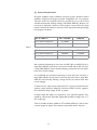
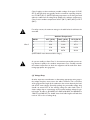
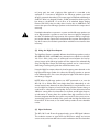
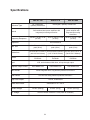
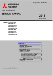
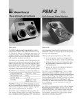
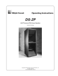
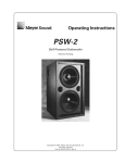
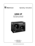
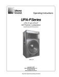
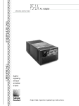
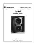
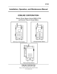
APL-10, APL-12, & APL-SB
SELF-POWERED CONCERT
SUBWOOFER SYSTEM MANUAL
© 2003 Apogee Sound International, LLC
Specifications subject to change without notice.
A 42-0835 / B 55-0040-01C Printed in U.S.A.
0308
Notice
Every effort was made to ensure that the information in this guide was complete and accurate at the time of
printing. However, information is subject to change.
IMPORTANT SAFETY INFORMATION
WARNING: To Reduce The Risk of Fire Or Electric Shock, Do Not Expose This Apparatus To Rain Or
Moisture.
Always
1.
2.
3.
4.
5.
6.
7.
8.
9.
10.
11.
12.
13.
follow these basic safety precautions when installing and using the unit:
Read these instructions.
Keep these instructions.
Heed all warnings.
Follow all instructions.
Do not use this apparatus near water.
Clean only with dry cloth.
DO NOT block any ventilation openings. Install in accordance with the manufacturer's instructions.
Do not install near any heat sources such as radiators, heat registers, stoves, or other apparatus
(including amplifiers) that produce heat.
Do not defeat the safety purpose of the polarized or grounding-type plug. A polarized plug has two
blades with one wider than the other. A grounding-type plug has two blades and a third grounding
prong.The wide blade, or the third prong, are provided for your safety. If the provided plug does not
fit into your outlet, consult an electrician for replacement of the obsolete outlet.
Protect the power cord from being walked on or pinched, particularly at plugs, convenience
receptacles, and the point where they exit from the apparatus.
Only use attachments/accessories specified by the manufacturer.
Unplug this apparatus during lightning storms or when unused for long periods of time.
Refer all servicing to qualified service personnel. Servicing is required when the apparatus has been
damaged in any way, such as power-supply cord or plug is damaged, liquid has been spilled or objects
have fallen into the apparatus, the apparatus has been exposed to rain or moisture, does not operate
normally, or has been dropped.
CAUTION
RISK OF ELECTRIC SHOCK
DO NOT OPEN
CAUTION: TO PREVENT THE RISK OF ELECTRIC
SHOCK, DO NOT REMOVE COVER (OR BACK). NO
USER-SERVICEABLE PARTS INSIDE. REFER SERVICING
TO QUALIFIED PERSONNEL.
The lightning flash with arrowhead symbol, within an equilateral triangle, is intended to alert the user to the presence of uninsulated
"dangerous voltage" within the product's enclosure that may be of
sufficient magnitude to constitute a risk of electric shock to persons.
The exclamation point within an equilateral triangle is intended to
alert the user to the presence of important operating and maintenance (servicing) instructions in the literature accompanying the
appliance.
2
Table of Contents
Precautions & Safety Notes . . . . . . . . . . . . . . . . . . . . . . . . . . 4
Introduction . . . . . . . . . . . . . . . . . . . . . . . . . . . . . . . . . . . . . . . 7
The Concept of Integration. . . . . . . . . . . . . . . . . . . . . . . . . . . 7
AC Power Requirements . . . . . . . . . . . . . . . . . . . . . . . . . . . . 9
Audio Signals . . . . . . . . . . . . . . . . . . . . . . . . . . . . . . . . . . . . . 14
Amplifiers . . . . . . . . . . . . . . . . . . . . . . . . . . . . . . . . . . . . . . . . 17
Installation . . . . . . . . . . . . . . . . . . . . . . . . . . . . . . . . . . . . . . . 18
Signal Processing. . . . . . . . . . . . . . . . . . . . . . . . . . . . . . . . . . 19
Using the APL-10, -12, and -SB . . . . . . . . . . . . . . . . . . . . . . . 21
Troubleshooting & Field Repairs . . . . . . . . . . . . . . . . . . . . . . 29
Troubleshooting Chart . . . . . . . . . . . . . . . . . . . . . . . . . . . . . . 32
Amplifier Panel Details . . . . . . . . . . . . . . . . . . . . . . . . . . . . . . 33
Specifications . . . . . . . . . . . . . . . . . . . . . . . . . . . . . . . . . . . . . 34
Line Drawings. . . . . . . . . . . . . . . . . . . . . . . . . . . . . . . . . . . . . 35
Warranty Information . . . . . . . . . . . . . . . . . . . . . . . . . . . . . . . IBC
3
Precautions &
Safety Notes
English
• To reduce the risk of electric shock, disconnect the AC mains power cable
before installing audio cable. Reconnect the power cord only after making all
signal connections.
• Connect the loudspeaker only to a three-pole, three-wire grounding mains
receptacle. The receptacle must be connected to a fuse or circuit breaker.
Connection to any other type of receptacle poses a shock hazard and may
violate local electrical codes.
• Do not install the speaker in wet or humid locations without using weather protection equipment from Apogee Sound.
• Do not allow water or any foreign object to get inside the loudspeaker. Do
not put objects containing liquid on, or near, the unit.
• To reduce the risk of overheating the loudspeaker, avoid exposing it to
direct sunlight. Do not install the unit near heat-emitting devices or appliances, such as a room heater or stove.
• The loudspeaker contains potentially hazardous voltages. Do not attempt to
disassemble the unit. The unit contains no user-serviceable parts. Repairs
should be performed only by factory trained service personnel.
Francais
• Pour réduire le risqué d’électrocution, débrancher la prose principale de
l’haut-parleur, avant d’installer le cable d’interface allant à l’audio. Ne
rebrancher le bloc d’alimentation qu’après avoir effectué toutes les connections.
• Branchez l’haut-parleur dans une prise de courant à 3 dérivations (deux
pôles et la terre). Cette prose doit être munie d’une protection adéquate
(fusible ou coupe-circuit). Le branchement dans tout autre genre de prose
pourrait entraîner un risqué d’électrocution et peut constituer une infraction
à la réglementation locale concernant les installations électriques.
• Ne pas installer l’haut-parleur dans un endroit où il y a de l’eau humidité
excessive.
• Ne pas laisser de l’eau ou tout objet pénétrer dans l’haut-parleur. Ne pas
placer decipients contenant un liquide sur cet appareil, ni à proximité de
celuici.
• Pour éviter une surchauffe de l’haut-parleur, conserver-la à l’abri du soleil.
Ne pas installer à proximité d’appareils dégageant de la chaleur tells que radiateurs ou appareils de chauffage.
4
• Ce haut-parleur contient des circuits haute tension présentant un danger.
Ne jamais essayer de le démonter. Il n’y a aucun composant qui puisse être
réparé par l’utilisateur.Toutes les reparations doivent être effectuées par du
personnel qualifié et agree par le constructeur.
Deutsch
• Um die Gefahr eines slektrischen Schlages auf ein Minimum zu reduzieren,
den Lautsprecher vom Stromnetz trennen, bevor ggf. Ein AudioSchnittstellensignalkabel angeschlossen wird. Das Netzkabel erst nach
Herstellung aller Signalverbindungen wieder einstecken.
• Der Lautsprecher an eine geerdete zweipolige Dreiphasen-Netzsteckdose
anschließen. Die Steckdose muß mit einem geeigneten Abzweigschutz
(Sicherung oder Leistungsschalter) verbunden sein. Der Anschluß der unterbrechungsfreien Stromversorgung an einen anderen Steckdosentyp kann zu
Stromschlägen führen und gegen die örtlichen Vorschriften verstoßen.
• Der Lautsprecher nict an einem Ort aufstellen, an dem sie mit Wasser oder
übermäßig hoher Luftfeuchtigkeit in Berührung kommen könnte.
• Darauf achet, daß weder Wasser noch Fremdkörper in das Innere den
Lautsprecher eindringen. Keine Objekte, die Flüssigkeit enthalten, auf oder
neben die unterbrechungsfreie Stromversorgung stellen.
• Um ein Überhitzen dem Lautsprecher zu verhindern, das Gerät vor direkter Sonneneinstrahlung fernhalten und nicht in der Nähe von wämeabstrahlenden Haushaltsgeräten (z.B. Heizgerät oder Herd) aufstellen.
• Im Inneren diesem Lautsprecher herrschen potentiell gefährliche
Spannungen. Nicht versuchen, das Gerät zu öffnen. Es enthält keine vom
Benutzer reparierbaren Teile. Reparaturen dürfen nur von ausgebildetem
Kundenienstpersonal durchgeführt werden.
Español
• Para reducir el riesgo de descarga eléctrica, desconecte de la red el altoparlante antes de instalar el cable de señalización de interfaz de la segnale.Vuelva
a conectar el conductor flexible de alimentación solamente una vez efectuadas todas las interconexiones de señalizatción.
• Conecte el altoparlante a un tomacorriente bipolar y trifilar con neutro de
puesta a tierra. El tomacorriente debe estar conectado a la protección de
derivación apropiada (ya sea un fusible o un disyuntor). La conexión a
cualquier otro tipo de tomacorriente puede constituir peligro de descarga
eléctrica y violar los códigos eléctricos locales.
5
• No instale el altoparlante en lugares donde haya agua o humedad excesiva.
• No deje que en el altoparlante entre agua ni ningún objeto extraño. No
ponga objetos con líquidos encima de la unidad ni cerca de ella.
• Para reducir el riesgo de sobrecalentamiento, no exponga la inidad a los
rayos directos del sol ni la instale cerca de artefactos que emiten calor, como
estufas o cocinas.
• Este altoparlante contiene niveles de voltaje peligrosos en potencia. No
intente desarmar la unidad, pues no contiene piezas que puedan ser repardas por el usuario. Las reparaciones deben efectuarse únicamente por parte
del personal de mantenimiento capacitado en la fábrica.
6
Introduction
Apogee Powered Loudspeaker Systems are highly-engineered products that
combine advanced-technology amplifiers, sophisticated signal processing, and
state-of-the-art drivers housed in rugged, roadworthy loudspeaker enclosures. They are suitable for a wide variety of applications, ranging from
portable use for shows and events in all types of venues to permanent installations in auditoriums, churches, theaters, stadiums, meeting rooms, boardrooms, and similar locations.
The APL-10,APL-12, and APL-SB are large format, high-powered subwoofers,
capable of providing clean, undistorted low frequency sound at very high output levels.They form powerful arrays when used in multiples with like units.
The enclosures are designed for easy truck-packing and handling, and can be
safely flown from their built-in rigging points. They are designed to augment
Apogee’s full-range powered speaker family, but they are equally effective
when used with conventional, non-powered loudspeakers. The APL
-10, -12, and -SB feature extended bass down to 38 Hz, 32 Hz, and 35 Hz,
respectively, rapid transient response, and exceptionally low distortion, making them capable of fulfilling a wide range of professional sound reinforcement requirements.
Apogee powered products are exhaustively engineered and finely crafted.
They will provide years of trouble-free service if care is taken in their use and
maintenance. It is recommended that you read this manual and retain it in a
convenient location for future reference.
The Concept
of Integration
Why a Powered Loudspeaker?
Apogee’s powered speaker systems further the company’s original concept
of processor-based loudspeakers. By combining advanced electronic signal
processing with precisely matched amplifiers and integrating this package into
the speaker enclosure itself, a number of engineering improvements result.
Some of these are:
• The internal signal processor corrects driver and enclosure anomalies, and
provides required crossovers, time-domain alignment, and protection circuits.
• The amplifier’s power output, headroom, frequency response and dynamic
range are optimized for each model of loudspeaker system.
• The gain structure of the signal processor and amplifiers are always perfectly matched.
7
• An integrated speaker system is able to use current sensors as well as voltage sensors (VIProtect™) to provide information to the processor’s protection circuits. The result is more accurate control of the drivers’ mechanical
and thermal limits, and therefore better protection under abusive conditions.
• The amplifier output cables are kept to very short lengths, thereby reducing cable losses to nearly zero.
These engineering advancements result in the following benefits:
• All aspects of the loudspeaker system’s performance are maximized. Sonic
quality, power output capability, flatness of response, distortion, and behavior
under abusive conditions meet remarkably high standards.
• Reliability is increased because the internal amplifiers deliver appropriate
power levels to the drivers, without danger of over-powering or under-powering.
• Setup is quick and easy - all key circuitry is self-contained and factory-interconnected.There is no longer a need for the time-consuming mounting and
wiring of processors and amplifiers in outboard rack enclosures.
• Powered speakers save valuable truck and stage space previously allocated
for amplifier racks. Load-ins and load-outs are quicker and easier than with
conventional systems.
• Powered speakers weigh less than equivalent non-powered speakers and
amp racks, resulting in easier handling and reduced shipping costs.
• Powered speakers cost less and offer higher value than the equivalent nonpowered speaker, processor, amplifier, and rack combination.
8
AC Power
Requirements
(1) AC Power Connector and Cable
The APL-10, -12, and -SB use a PowerCon® 3-pole AC mains connector for
their power inlet (see Figure #1). When joined to the mating PowerCon
connector supplied with the AC line cord, the connector pair locks in place
to prevent inadvertent disconnection. PowerCon connectors are durable,
inexpensive, and readily obtainable.
Figure 1
The AC PowerCon cable assembly provided with your APL-10, -12, or -SB is
equipped with an AC mains plug compatible with the power service in the
country of sale. If you need to change this plug or to construct special purpose power cables, the wiring must follow the convention shown in Figure #2.
Brown - Hot
Blue - Neutral
Figure 2
Yellow/Green - Earth Ground
9
Hot
Ground
Figure 3
Neutral
Interior of PowerCon connector showing the wiring terminal
All AC power plugs must always be of the 3-pole grounding type.
DO NOT DEFEAT THE GROUND CONNECTION BY USING
AN AC GROUND LIFT ADAPTER, OR BY CUTTING THE
GROUND PIN OF THE AC POWER PLUG.
(2) Voltage Range
The APL-10, -12, and -SB are manufactured for nominal line voltages of either
120V AC or 230V AC.
NOTE:The 120V AC model is suitable for use at 100V AC with only a small
reduction in power capability.
Before applying power, carefully check the Line Voltage Label on the rear
panel located by the AC Mains Power Input connector to insure compatibility with the local AC mains supply. If your conditions of use change, the APL10, -12, and -SB can be modified for alternate line voltage by a qualified service technician.You will need to contact your Apogee dealer or distributor and
request a powered subwoofer line voltage adapter kit for each powered subwoofer that you wish to change. These kits are available in two versions: to
adapt a unit manufactured for 120V AC to 230V AC, or, to adapt a unit manufactured for 230V AC to 120V AC.
The 120V AC version will function safely within a range of 90V to 132V.
The 230V AC version will function safely within a range of 200V to 253V.
Voltages above the rated maximum should be avoided at all times or damage
may occur!
10
(3) Current Requirements
All power amplifiers require sufficient current for proper operation and the
amplifiers designed into Apogee powered loudspeakers are no exception.
Chart #1 shows the required current for one APL-10, -12, or -SB at three
standard international working voltages (120, 240, & 100V AC). Because current drain is ultimately a function of the program source, Chart #1 shows
both the theoretical maximum, and what can be expected under typical highlevel program conditions:
APL-10 / APL-12
Max. Continuous Amperes
Typical Program Conditions
100 / 120V AC
240V AC
19.6 ARMS
9.8 ARMS
14 ARMS (OR
LESS)
7 ARMS (OR
LESS)
Chart 1
APL-SB
Max. Continuous Amperes
Typical Program Conditions
100 / 120V AC
240V AC
9.8 ARMS
4.9 ARMS
7 ARMS (OR
LESS)
3.5 ARMS (OR
LESS)
We recommend powering no more than one APL-10 or one APL-12 from a
single 20A, 120V AC circuit, and no more than two APL-10s or APL-12s from
a single 20A, 240V AC circuit, thereby allowing a margin for line loss and/or
lower than normal voltages.
For the APL-SB, we recommend powering no more than two units from a
single 20A, 120V AC circuit, and no more than four units from a single 20A,
240V AC circuit, thereby allowing a margin for line loss and/or lower than
normal voltages.
To determine the total current requirement for a system of powered loudspeakers, simply add their Maximum Continuous RMS Currents together,
then calculate a safety margin of 25% or greater.
If special length AC cables are required for your powered speakers, they
should be constructed of durable, high-quality portable cordage such as S,
SO, or SJO type.
Chart 2 provides the basic guidelines of The National Electric Code for four
common gauges of copper wire related to permissible load in amperes.
11
Chart 2 applies to three-conductor portable cordage of the types S, SO, SP,
SPT, SJ, and SJO, which are typically rated at a maximum operating temperature of 140°F (60° C). (NOTE: Operating temperature is the heat generated
within the cable from the voltage drop added to the ambient temperature.)
Chart 2 covers ambient temperatures of 86°F (30°C), 104°F (40°C), & 122°F
(50°C).
For safety reasons, the maximum ratings in the table below should never be
exceeded.
Ambient Temperature
86°F (30°C)
104°F (40°C)
122°F (50°C)
14
15 A
12.3 A
6.9 A
12
20 A
16.4 A
8.7 A
10
25 A
20.5 A
14.5 A
8
35 A
28.7 A
20.3 A
AWG#
Chart 2
(NOTE: AWG means American Wire Gauge.)
As you can readily see from Chart 2, the maximum permissible current ratings decrease rapidly as the ambient temperature rises. Carefully consider
the ambient temperature in which the equipment will be used when determining appropriate wire gauge size.
(4) Voltage Drop
Another important consideration in determining appropriate wire gauge is
the voltage drop that occurs across the cable’s resistance. This is a function
of the gauge and the length of the conductors, the current drawn by the load,
and the AC mains voltage. Generally speaking, the permissible voltage drop
should not exceed 2.5% of the working voltage for audio loads. Chart 3
shows voltage drop as a percentage of the nominal working voltage for typical lengths of cables in #14 AWG, #12 AWG, #10 AWG, and #8 AWG at
120V AC and 240V AC.The shaded areas show cable lengths and loads that
result in 2.5% or less of voltage drop.
12
POWER CABLE VOLTAGE DROP (IN PERCENTAGE OF NOMINAL VOLTAGE)
Chart 3
#14 AWG, 120V AC
Length in Feet 5A
25'
0.6%
50'
1.2%
75'
1.8%
100'
2.4%
125'
3.0%
150'
3.6%
175'
4.3%
200'
4.9%
225'
5.5%
250'
6.1%
275'
6.7%
300'
7.3%
10A
1.2%
2.4%
3.6%
4.9%
6.1%
7.3%
8.5%
9.7%
10.9%
12.2%
13.4%
14.6%
15A
1.8%
3.6%
5.5%
7.3%
9.1%
10.9%
12.8%
14.6%
16.4%
18.2%
20.1%
21.9%
20A
2.4%
4.9%
7.3%
9.7%
12.2%
14.6%
17.0%
19.5%
21.9%
24.3%
26.8%
29.2%
#14 AWG, 240V AC
Length in Feet 5A
25'
0.3%
50'
0.6%
75'
0.9%
100'
1.2%
125'
1.5%
150'
1.8%
175'
2.1%
200'
2.4%
225'
2.7%
250'
3.0%
275'
3.3%
300'
3.6%
10A
0.6%
1.2%
1.8%
2.4%
3.0%
3.6%
4.3%
4.9%
5.5%
6.1%
6.7%
7.3%
15A
0.9%
1.8%
2.7%
3.6%
4.6%
5.5%
6.4%
7.3%
8.2%
9.1%
10.0%
10.9%
20A
1.2%
2.4%
3.6%
4.9%
6.1%
7.3%
8.5%
9.7%
10.9%
12.2%
13.4%
14.6%
#12 AWG, 120V AC
Length in Feet 5A
25'
0.4%
50'
0.8%
75'
1.1%
100'
1.5%
125'
1.9%
150'
2.3%
175'
2.7%
200'
3.1%
225'
3.4%
250'
3.8%
275'
4.2%
300'
4.6%
10A
0.8%
1.5%
2.3%
3.1%
3.8%
4.6%
5.4%
6.1%
6.9%
7.7%
8.4%
9.2%
15A
1.1%
2.3%
3.4%
4.6%
5.7%
6.9%
8.0%
9.2%
10.3%
11.5%
12.6%
13.8%
20A
1.5%
3.1%
4.6%
6.1%
7.7%
9.2%
10.7%
12.3%
13.8%
15.3%
16.8%
18.4%
#12 AWG, 240V AC
Length in Feet 5A
25'
0.2%
50'
0.4%
75'
0.6%
100'
0.8%
125'
1.0%
150'
1.1%
175'
1.3%
200'
1.5%
225'
1.7%
250'
1.9%
275'
2.1%
300'
2.3%
10A
0.4%
0.8%
1.1%
1.5%
1.9%
2.3%
2.7%
3.1%
3.4%
3.8%
4.2%
4.6%
15A
0.6%
1.1%
1.7%
2.3%
2.9%
3.4%
4.0%
4.6%
5.2%
5.7%
6.3%
6.9%
20A
0.8%
1.5%
2.3%
3.1%
3.8%
4.6%
5.4%
6.1%
6.9%
7.7%
8.4%
9.2%
#10 AWG, 120V AC
Length in Feet 5A
25'
0.2%
50'
0.5%
75'
0.7%
100'
1.0%
125'
1.2%
150'
1.4%
175'
1.7%
200'
1.9%
225'
2.2%
250'
2.4%
275'
2.6%
300'
2.9%
10A
0.5%
1.0%
1.4%
1.9%
2.4%
2.9%
3.4%
3.8%
4.3%
4.8%
5.3%
5.8%
15A
0.7%
1.4%
2.2%
2.9%
3.6%
4.3%
5.0%
5.8%
6.5%
7.2%
7.9%
8.7%
20A
1.0%
1.9%
2.9%
3.8%
4.8%
5.8%
6.7%
7.7%
8.7%
9.6%
10.6%
11.5%
#10 AWG, 240V AC
Length in Feet 5A
25'
0.1%
50'
0.2%
75'
0.4%
100'
0.5%
125'
0.6%
150'
0.7%
175'
0.8%
200'
1.0%
225'
1.1%
250'
1.2%
275'
1.3%
300'
1.4%
10A
0.2%
0.5%
0.7%
1.0%
1.2%
1.4%
1.7%
1.9%
2.2%
2.4%
2.6%
2.9%
15A
0.4%
0.7%
1.1%
1.4%
1.8%
2.2%
2.5%
2.9%
3.2%
3.6%
4.0%
4.3%
20A
0.5%
1.0%
1.4%
1.9%
2.4%
2.9%
3.4%
3.8%
4.3%
4.8%
5.3%
5.8%
#8 AWG, 120V AC
Length in Feet 5A
25'
0.2%
50'
0.3%
75'
0.5%
100'
0.6%
125'
0.8%
150'
0.9%
175'
1.1%
200'
1.2%
225'
1.4%
250'
1.5%
275'
1.7%
300'
1.8%
10A
0.3%
0.6%
0.9%
1.2%
1.5%
1.8%
2.1%
2.4%
2.7%
3.0%
3.3%
3.6%
15A
0.5%
0.9%
1.4%
1.8%
2.3%
2.7%
3.2%
3.6%
4.1%
4.5%
5.0%
5.5%
20A
0.6%
1.2%
1.8%
2.4%
3.0%
3.6%
4.2%
4.8%
5.5%
6.1%
6.7%
7.3%
#8 AWG, 240V AC
Length in Feet 5A
25'
0.1%
50'
0.2%
75'
0.2%
100'
0.3%
125'
0.4%
150'
0.5%
175'
0.5%
200'
0.6%
225'
0.7%
250'
0.8%
275'
0.8%
300'
0.9%
10A
0.2%
0.3%
0.5%
0.6%
0.8%
0.9%
1.1%
1.2%
1.4%
1.5%
1.7%
1.8%
15A
0.2%
0.5%
0.7%
0.9%
1.1%
1.4%
1.6%
1.8%
2.0%
2.3%
2.5%
2.7%
20A
0.3%
0.6%
0.9%
1.2%
1.5%
1.8%
2.1%
2.4%
2.7%
3.0%
3.3%
3.6%
13
It’s useful to note the benefit of operating a powered loudspeaker system at
higher voltages (when possible). At 240V AC, current consumption is half
that of 120V AC and the resultant voltage drop for a given cable size and
length decreases by a factor of 4.This means that the cable can be four times
longer when used at 240V AC than at 120V AC. Higher voltages are
more efficient!
Audio Signals
(1) Input Impedance and Level
The APL-10, -12, and -SB were designed to receive a balanced-line signal on
their 3-pin female XLR type connector.They are also equipped with a 3-pin
Male XLR output connector, labeled “loop-through,” intended for the purpose of daisy-chaining multiple powered speakers together on a common signal feed.These input and output connectors are hard-wired in parallel; that is
to say, no active or passive buffer exists between the two connectors, they
are simply wired in parallel.This means that the loop-through connector will
always remain functional, even if AC power is interrupted to a speaker
“upstream” of other speaker(s) on the same feed circuit.
The input impedance is 10k-ohm, active balanced, and is intended to receive
a nominal +4 dBv input level (+4 dBv = full power). Because it’s common
practice to loop quite a few powered speakers together on a shared feeder
circuit, care must be taken to insure that the signal source is capable of driving the group of powered loudspeakers. For example, ten APL-12s present a
1k-ohm load to the signal source. This is well within the capability of most
line-level output drivers, but depending on the output impedance of the
source, some loss in level may occur.The formula to calculate such loss is:
RIx
Voltage Loss (dB) = 20 * Log (RIx +RS)
[
RS
VS
VI
RIx
]
Where: RS = Source Equipment Output Impedance
RIx = Combined Input Impedance of all APL Speakers
Note: VS = Unloaded Source Equipment Signal Voltage
VI = Loaded Signal Input Voltage to APL Speakers
For example, let’s say you’re driving ten APL-12s with a 100-ohm source
impedance.The formula to calculate loss would then be:
1000
Voltage Loss (dB) = 20 * Log (1000+100 ) = – 0.83 dB
[
]
NOTE: It is important to be aware of the potential losses that may occur
from combining multiple powered speakers on the same feed circuit.This is
particularly important when attempting to adjust audio levels among a large
system that employs multiple feed circuits with different numbers of powered speakers on each feed.
14
(2) Input and Output Connectors
The input and output connectors are wired as follows:
XLR Pin #
Function
Pin 1
Earth & Chassis Ground
Pin 2 Signal +
DIFFERENTIAL INPUT
Pin 3 Signal DIFFERENTIAL INPUT
Connector Case
Earth & Chassis Ground
A positive signal applied to pin 2 of the XLR will result in a positive acoustic
pressure wave (excursion) appearing at the front of the drivers in the speaker system. Conversely, a positive signal appearing at pin 3 of the XLR will
result in a negative acoustic pressure wave (recursion) appearing at the front
of the speaker system’s drivers.
(3) Phase Reverse Switch
The APL-10, -12, and -SB are equipped with an input polarity-reversal switch
(also called a phase reverse switch), located adjacent to its XLR input connector.When this switch is in the UP position (labeled Pin 2+), the description in Section 2 - "Input and Output Connectors" is correct. With this
switch in the DOWN position (labeled Pin 3+), the phase relationship will be
reversed.When the switch is DOWN, a positive signal applied to pin 2 of the
XLR will result in a negative acoustic pressure wave (recursion) appearing at
the front of the drivers in the speaker system. Conversely, a positive signal
appearing at pin 3 of the XLR will result in a positive acoustic pressure wave
(excursion) appearing at the front of the speaker system. More about the
appropriate use of this switch can be found in the, "Using the APL-10, -12,
and -SB" section.
Except in highly unusual circumstances, all subwoofers used in a common
sound system should have their Phase-Reverse Switches set in identical positions.
It is important to be aware of the position of the Phase Reverse Switch when
preparing to place the speaker in a difficult-to-reach location, such as when
flown. If by chance the APL-10, -12, or -SB is placed in an inaccessible location and the Phase Reverse Switch is in the opposite position from that
which is desired, a common phase-reverse barrel-type line adapter can be
used to swap the polarity of pin 1 and pin 2, thereby achieving the same
result as changing the position of the switch.
(4) High-Pass Output
The APL-10, -12, and -SB are equipped with a 100 Hz, 24 dB/octave High-Pass
Output.This output produces a signal that is identical in gain to the input sig-
15
nal (unity gain), but with a high-pass filter applied. It is intended to be
employed as a crossover, if desired, for the full-range speakers used with
Apogee’s powered subwoofer(s).The output signal is balanced and filtered to
avoid DC offset. It is designed to feed a +4 dBv (nominal) line-level input.The
line driver in the APL-10, -12, and -SB is of an advanced design (Analog
Devices SSM 2141) that can easily drive a load as low as 1000 ohms. This
means that quite a few full-range speakers can be fed from this output simultaneously.
If multiple subwoofers are present in a system and the full-range speakers are
to be high-passed, it is prudent to use more than one high-pass output for
the sake of redundancy. If a large portion of the system is fed by a single highpass output and that output ceases to function due to power interruption or
any other reason, the resultant system failure would be more extensive than
necessary.
(5) Using the High-Pass Output
The High-Pass Output is especially effective when full-range speakers, such as
APL-500s,APL-220s, or APL-800s, are positioned on or adjacent to the APL10, -12, or -SB. In such a case, an overlap will occur between the low frequency output of the full-range speaker and the output of the subwoofer. By
using the High-Pass Output, the full-range speakers can be “crossed over,”
eliminating a low frequency peak that would otherwise occur.
Using the High-Pass output reduces the low frequency power demand on the
high-passed full-range speaker; this allows the full-range speaker to operate
more efficiently, and in most cases, be played at higher levels before protective limiting is engaged.
NOTE: When the full-range speakers are NOT positioned on or near the
APL-10, -12, or -SB but flown some height above the subwoofer(s) or otherwise located some distance from the subwoofer(s), it may be better not to
use the High-Pass Output to feed the full-range speakers because doing so
could result in a ‘disjointed’ sound quality. If most of the information below
100 Hz is coming from the subwoofers on the floor and all higher frequency information is coming from the speakers flown high overhead, a loss of
acoustic integration between the systems may result. For this reason, we recommend that you listen carefully to the system with the High-Pass filter both
IN and OUT of the circuit, to see which mode provides the most desirable
results.
(6) Signal Indicator
The APL-10, 12 and SB are all equipped with a green LED Signal Indicator.
This indicator receives its signal from the VIProtect™ voltage and current
sensor circuit, and is intended to be used for verification that the subwoofers
16
are working properly.The LED will illuminate only if the following three conditions are met: audio is present at the input connector; the amplifier(s) are
operating properly, and the LF drivers are functioning properly.This indicator
is especially useful as an aid in visually checking large systems, where failure
of one subwoofer might otherwise go unnoticed.
Amplifiers
(1) Overview
The internal amplification package in both the APL-10 and -12 consists of
dual, fully-independent power supplies and dual, fully-independent 1000-watt
power amplifiers.
The APL-SB includes one power supply and one 1000-watt power amplifier.
These amplifiers and power supplies use numerous, proprietary design features that result in extremely low distortion, high reliability, and a very low
heat by-product. No fans are used or needed, eliminating the risk of a
mechanical device becoming noisy during a quiet performance due to bearing wear or contamination. The absence of fans also greatly simplifies maintenance, by eliminating the need to regularly check and clean air intake filters.
Patented Primary Drive Control™ power supplies drastically reduce the
overall size and weight of each speaker. Each 1000-watt amplifier, also patented, uses an output configured as class A/B but with the advantage of integrated, continuously tracking supply rails, thereby maintaining minimal voltage
drop through the output devices regardless of amplitude. The result is efficiency that rivals a switching-type amplifier, but with the sound quality of a
linear amp.
The unique design of the amplifiers also results in the ability to provide
exceptional transient response. This equates to a wider dynamic range and
more low-frequency “punch” than that of conventional amplifiers of a similar
power rating.
(2) Special Functions
The APL-10, -12, and -SB are equipped with a SLEEP mode. After initial activation, the system constantly seeks an input signal. If no signal is present for
approximately 30 minutes, the SLEEP circuitry will shut down the main
power supplies, the amplifier, and all but one section of the processor.When
in sleep mode, the yellow LED labeled SLEEP will illuminate on the rear panel.
Whenever a signal does occur, the system will rapidly “wake up,” ready for
use.The system awakens with a signal of any nature, from 20 Hz to 10 kHz,
applied at a level of -20 dBu or greater.
17
SLEEP mode greatly extends the life of the components, and reduces power
consumption at idle. It makes APL-10, -12, and -SB products appropriate for
locations where it may be difficult to access the speaker for routine powerup and power-down.
NOTE: If the system is to be left for long periods of time without use, it is
recommended that power be removed as a safety measure. In some regions,
power lines are subject to large voltage spikes from electrical storms or generator malfunction. If the power cable is removed, such occurrences cannot
damage the unit.
Installation
When installing and using the APL-10, -12, or -SB, some simple precautions
should be followed.These include:
(1) Maintain Proper Air Flow
The APL-10, -12, and -SB are radiant- and convection-cooled devices.The aluminum heat-exchanger mounted on the rear surfaces provides primary cooling of the system. Care must be taken to locate the units away from heat registers, heat-generating appliances, lighting equipment, and any other apparatus that could raise the temperature of the nearby air.
The APL-10, -12, and -SB require unimpeded air circulation in order to function properly (this is especially important when multiple units are used in
stacked and/or tight-pack configurations). The APL’s rear surface should be
located at least 18" away from walls and/or ceilings. Lamps, especially of the
high intensity or theatrical type, should never be allowed to shine directly on
the heat exchanger.
(2) Ambient Temperature
The APL-10, -12, and -SB are designed to be used in ambient temperatures
ranging from 32°F - 113°F (0°C - 45°C). Higher or lower temperatures
could cause system shutdown or result in early component failure. When
used outdoors on a hot day, take precautions to avoid direct sunlight on the
rear heat exchanger. Direct, intense sunlight can raise the temperature of the
heat exchanger to a point where the amplifiers may be required to shutdown to avoid permanent damage.
(3) More About Heating and Cooling
The APL-10, -12, and -SB have a relatively complex thermal dynamic system.
They contain several heat sources (amplifiers, power supplies, and drivers)
that generate significant heat but only when program material is being reproduced.They are cooled primarily through heat radiation from the rear panel
18
as well as by convection; and secondarily, by a small degree of air movement
generated by the cone drivers.
Because the heat output of the system is directly proportional to the duration and nature of the program material, the system may not reach thermal
stability for several hours after it is activated. For this reason, it is important
to test the system under actual conditions of use if questionable conditions
are present. Questionable conditions include:
(a) ambient temperature at or above the maximum rating
(b) intense sunlight or artificial light shining on the heat exchanger
(c) program material that runs for many hours without pause
(d) combinations of the above
Here’s a hypothetical example of what to look out for. An APL-12
might be set up outdoors in 85°F (29°C) temperature with sunlight shining
partially on the rear panel. Let’s assume it is tested during a 30-minute sound
check and all is well. Later that day, the ambient temperature rises to 99°F
(37°C) and the sunlight is now shining directly on the rear of the loudspeaker.The show starts, featuring dance tracks with no pause between song titles.
Under such extreme conditions, it is entirely possible that after a period of
service, the loudspeaker will shut off to protect itself from excessive heat.
Problems, such as the one described above, can be avoided by shading the
heat exchanger from direct sunlight.
Signal Processing
(1) Basic Concept
The APL-10, -12, and -SB use a highly-advanced signal processor contained
entirely within the unit. The processor provides the functions of an asymmetrical electronic crossover (36 dB/octave low-pass and 24 dB/octave highpass), fixed equalization to compensate for driver/enclosure anomalies, and
advanced protective limiting circuits. It also provides a low-frequency alignment circuit that acts synergistically with the enclosure’s ports.This serves to
extend the bass response well below that of a conventional enclosure of a
similar size. All circuits in the audio path utilize the highest quality, most upto-date semi-conductor technologies available today.
The processor is the key to the extraordinary sound quality of the loudspeaker system. Unlike generic crossovers, either digital or analog, the APL
processor was carefully designed in tandem with the drivers and the
enclosure, to provide optimum performance.
(2) Driver Protection
Apogee APL-Series speakers utilize a specialized, highly-evolved Command
19
Control limiting system.This system comprises three separate layers of protection triggered by an infinite variation of possible program conditions. Data
is received on four independent sensor circuits, including Apogee’s exclusive
VIProtect™ current sensors, and is processed by an analog computer to prohibit the drivers from over-excursion, excessive RMS levels, and excessive
instantaneous peak levels. By sensing voltage and current, the limiter circuits
can compensate for changes in voice coil temperature, ensuring that accurate
protection levels are always maintained.
All of this occurs without compromising dynamic range or otherwise unnaturally compressing the program material. The protection circuits only act
when the drivers would otherwise be damaged and, therefore, are exceptionally transparent. They are effectively “out of circuit” when below the
threshold of engagement.The result is an extremely clean sound quality, with
effective control of potential damage to the drivers from abusive conditions.
A limiter LED is located on the rear panel of the APL-10, -12, and -SB, intended to indicate the deployment of the limiters. It is not uncommon to see this
LED illuminate regularly, such as on downbeats and crescendos.
If the LED appears to be "on" more than "off" (i.e., if it is continuously flashing or glowing at a steady state), the loudspeaker system is being pushed too
hard for its size and power output capability.To correct this, reduce the drive
level to the speaker system, or install additional speakers to achieve the SPL
(Sound Pressure Level) required for the application.
(3) A Word About Limiters
Properly designed protective limiters can do wonders to help prevent driver damage and extend normal driver life, but are by no means a panacea.
Apogee limiters do not exhibit “brick-wall” characteristics, as these type of
limiters seriously degrade sound quality. Apogee’s intelligently engineered
limiter circuits provide an excellent measure of protection, while maintaining
sonic purity.
These limiter circuits are capable of effectively reducing program levels that
would otherwise damage the system’s drivers.This takes place with little or
no loss of sonic quality or dynamic range, because the circuits are designed
so that they only engage when driver non-linearity or driver damage would
otherwise occur. However, when a limiter is pushed well past its threshold of
engagement to the point where it is continually “in circuit”, by nature, it
increases the duty-cycle of the program material. This happens because, as
the limiter decreases peak amplitudes, RMS values increase, causing the drivers to heat beyond normal. Additional circuits could be employed to reduce
levels and “clamp” the output of the system, but such circuits would represent a high level of intervention and be very audible in their action.The proper solution is for the operator to recognize that the system is being pushed
past its capabilities and either reduce operating levels or add additional
speaker systems to provide the desired Sound Pressure Level (SPL).
20
Using the APL-10,
-12, and -SB
(1) Overview
The APL-10, -12, and -SB can be used in many ways and for many applications. In its simplest form, one APL-10, -12, or -SB placed at each side of the
stage will add dramatic low frequency impact to a typical full-range system in
a club, church, or theatre.
A full-blown array of fifty or sixty APL-10, -12, or -SBs, properly positioned,
can provide intense low-frequency power for large-scale concerts, both
indoors and out.
The nature of low-frequency sound waves and how they behave in space
should be understood, at least in rudimentary form, to operate an APL-10,
-12, or -SB system to your best advantage. Low frequency waves are very
long. A 30 Hz wavelength is approximately 35 feet in length and a 100 Hz
wavelength is approximately 11.3 feet in length (varying a bit with temperature).
Because low-frequency waves are significantly greater in length than higher
frequency waves, they behave quite differently than other wavelengths.
First, a long waveform does not ‘see’ a small or moderate-sized obstruction
as an obstacle; it simply diffracts around the barrier as if it’s not there.
Second, the substantial length of low frequency waves makes it difficult to distinguish their source direction. (This is why a single subwoofer can often be
used to augment a stereo pair of full-range speakers, without sacrificing
stereo separation and image.)
Third, low frequency waves tend to join together very graciously (if they are
in phase and in time with one another), even if their sources are separated
by a considerable distance. Most professional sound engineers have experienced an intense bass elevation in the middle of certain rooms, generated by
a stack of speakers placed at either side of the stage.
Understanding how low-frequency waves transmit can be very helpful in
planning and designing optimum sound systems.There are many useful texts
available on this subject. Recommended reading: "Fundamentals of Sound"
and "Psychoacoustics" by F. Alton Everest in the "Handbook for Sound
Engineers" published by Howard Sams & Co.
To help you get the most from your APL-10, -12, or -SB powered loudspeakers, here are some basic guidelines.
(2) Placement
The APL-10, -12, and -SB will benefit greatly in terms of power output by
being placed adjacent to a boundary surface (or surfaces). In practical terms,
this means putting the APL-10, -12, or -SB on the floor, on the ground, by a
21
rear wall or ceiling (being careful not to restrict air flow to the heat exchanger), or in a corner.
When located by a wall (half space), power output will increase by 3 dB (see
Figure 4) when compared to placement in a free-field environment (see
Figure 5).When located at the junction of two walls (quarter space), power
output will increase by 6 dB over that of a free-field environment (see Figure
6). Finally, when located at the junction of three walls (eighth space), power
output increase a full 9 dB (see Figure 7).
It’s not always possible to utilize walls and corners for extra power. The nearest wall or corner might result in the subwoofer being positioned behind the
microphones, causing feedback, or, too far out of time sync with the full-range
speakers. Sometimes the sound quality from a subwoofer located in a corner
is not desirable due to other aspects of the room’s acoustics. However, when
wall and corner positions are appropriate to use, they offer a tremendous
increase in power output.
Figure 4 - Half Space
Figure 5 - Free Space
l
l
3dB
0dB
Figure 6 - Quarter Space
Figure 7 - Eighth Space
l
l
6dB
9dB
22
(3) Configurations of Multiple Units
When APL-10, -12, or -SBs are used in multiples, certain techniques can be
applied to help achieve the desired results. To start with, the enclosures
should be placed touching one another. Separating them, even a little, limits
their power summation and can generate lobes and unwanted response
anomalies.
Multiple units configured in a line will exhibit increased directionality in the
axis of the line. For example, placing four or more APL-10, -12, or -SBs horizontally end-to-end narrows their horizontal coverage pattern without
changing the vertical pattern (NOTE: dispersion is essentially omni-directional for a single unit). Such a configuration can be used to increase the coverage distance in a large venue, such as a deep shed. Conversely, stacking four
APL-10, -12, or -SBs in a vertical line will narrow their vertical coverage angle
without changing their horizontal dispersion.This configuration could be useful to penetrate long distances in a flat outdoor space, such as a soccer field.
RULE OF THUMB:Whenever the coverage angle is narrowed, on-axis power
is also increased. The greater the number of enclosures placed in a line, the
narrower the dispersion angle will be, with a corresponding increase in summation and forward-radiated power. The lowest frequency that will exhibit
such behavior is directly a function of the array size.
The length of the array must be at least a 1/4 wavelength of the frequency of
interest for any semblance of directional control to occur.At 1/2 wavelength,
directional control starts to become effective.As the length of the line grows,
directional control (i.e., narrowing of the dispersion pattern) increases continually, becoming more and more effective.
Chart 4 depicts wavelength vs. frequency (at ISO preferred frequencies)
throughout the operating range of the APL-10, -12, or -SB, in relation to the
number of APL-10, -12, or -SBs that would approximate a 1/2 wavelength of
the frequency of interest when arrayed end-to-end and top-to-bottom:
Chart 4
APL-10
APL-12
APL-SB
Frequency
in Hz
Wavelength
feet / meters
No. end-to-end/
No. top to bottom
No. end-to-end/
No. top to bottom
No. end-to-end/
No. top to bottom
25
44.8 / 13.7
9 / 12
6/9
9 / 12
31.6
35.6 / 10.9
7 / 9.5
5/7
7 / 9.5
40
28.3 / 8.6
5 / 7.5
4/6
5 / 7.5
50
22.5 / 6.9
4/6
3 / 4.5
4/6
63
17.9 / 5.4
3.5 / 5
2 / 3.5
3.5 / 5
80
14.2 / 4.3
3/4
2/3
3/4
100
11.3 / 3.4
2/3
2/2
2/3
23
APL-10, -12, and -SBs can also be combined in an L-format (See Figure 8).
The L-format exhibits directional control in both axes, and is often the best
choice for deploying a large number of speakers in sizeable venues.
Figure 8
Finally, APL-10, -12, and -SBs can be configured into a block arrangement (See
Figure 9).This arrangement also exhibits directional control in both axes, but
it does not take full advantage of the boundary surface effect (see "Using the
APL-10, -12, and -SB – 2-Placement" (pg. 21). Although this configuration is
certainly more effective than scattering the units about at random, it has a
tendency to produce unwanted lobing, sometimes leading to a muddy bass
response.
Figure 9
24
(4) Polarity (Phase)
The optimum polarity for the APL-10, -12, or -SB subwoofer is a function of
its placement in relation to the full-range speaker(s) it is augmenting.This is
known as the phase relationship of the two systems although absolute phase
also plays a role in the equation, as we’ll see later.
If the APL-10, -12, or -SB are directly under or over the full-range speaker(s),
in nearly all cases the polarity should be normal; that is, the same as the fullrange speaker. (NOTE: A positive signal applied to pin 2 of the XLR input
connector will result in a positive wavefront appearing at the front of the
APL-10, -12, or -SB if the Phase Reverse Switch is set in the normal position).
As long as the full-range speaker system exhibits a like response (i.e., produces a positive wavefront when excited with a positive signal on pin 2 of its
amplifier’s input), both systems will be in-phase with each other. Often,
depending on the characteristics of full-range speaker(s), when both systems
are in-phase with each other, a low frequency peak will occur in the region
where the two systems overlap.This is normal and can be dealt with by one
of the following:
(a) The low frequency peak in the overlap region can be filtered out with an
equalizer. (NOTE: Usually equalizing only the full-range system is sufficient.To
this end, Apogee’s powered full-range speakers are equipped with a 100 Hz
high-pass switch, making it easy to adapt them for use with subwoofers.)
However, in some situations (such as when a large number of subwoofers
and full-range speakers are deployed), it may be necessary to equalize both
the full-range system and the subwoofer system to achieve a perfectly flat
response through the overlap region.
(b) The full-range speaker system can be driven from the APL-10, -12, or
-SB’s high-pass output. This output effectively attenuates the energy to the
full-range speaker system in the overlap region, eliminating the low-frequency build-up. It behaves in a like manner to the 100 Hz high-pass switch supplied on Apogee’s full-range powered loudspeakers.
(c) The APL-10, -12, and -SB can be switched out-of-phase with the full-range
system.This will cause a deep cancellation through the overlap region and is
not recommended. It may sound better than the low-frequency accentuation
generated by the overlap, but it can (and will) adversely affect the system’s
impulse and phase response, as well as causing the drivers to work harder
for less output (because of the cancellations taking place). It is far better
practice to properly equalize the system than to take a shortcut by using cancellation to shape the frequency response of the system.
If an APL-10, -12, or -SB is NOT located directly over or under the full-range
system, but rather some distance away from it, the proper phase relationship
will need to be determined.This is also true if the APL-10, -12, or -SB is offset in depth, such as in front of, or behind, the full-range system.
25
An easy way to determine the best phase relationship is to listen to a lowfrequency source while standing in front of the system and have someone
change the setting of the Phase Reverse Switch from normal to reverse while
you listen. In one setting you should hear a distinct increase in mid-bass, and
in the other setting you should hear a distinct reduction in mid-bass. It’s
important to listen in front of the speaker system for accurate acoustic evaluation.
If you do not hear a change in the bass response, it’s because either:
(a) The full-range system that the subwoofer is being used with does not
reproduce enough bass output to cause either a cancellation or addition with
the subwoofer’s output, or
(b) The full-range and subwoofer systems are displaced by a distance of
around 1/4 wavelength of the frequency region where they both provide the
most output. In such a case, neither polarity position will result in addition or
cancellation, hence the lack of change in response.
The solution to situation ‘a’ is to leave the subwoofer in the normal position.
No harm will come if the full-range system simply cannot reproduce energy
low enough to compete (either positively or negatively) with the subwoofer’s
output.
The solution to situation ‘b’ is to either change the physical relationship of
the two speaker systems, or delay one of the two systems (whichever one is
positioned closer to the listeners) with a digital delay unit. A good quality
measurement system that can read and depict phase response and/or
impulse response would be very useful in such a situation. However, without
such a system, you can determine an effective delay time by trial and error.
Simply increment the delay time in small steps (1 ms) until the action of
changing the Phase Reverse Switch produces the maximum cancellation in
one setting, and maximum addition in the opposite setting. With the switch
set for maximum acoustic addition, the two systems should be in time and in
phase with one another.You will have preserved optimum impulse and phase
response and can now filter out any objectionable mid-bass overlap with an
equalizer.
(5) Absolute Phase
Quite a bit has been written about absolute phase, particularly in regard to
studio recording and hi-fi sound reproduction.The subject is, however, often
ignored in the field of sound reinforcement.
Essentially, absolute phase refers to configuring the system so that the electro-acoustic drivers move toward the listener and produce a positive wavefront upon the first cycle of excitation by source material.This means that at
the instant of impact, when the head of the kick drum moves outward
towards the microphone, the speaker cones also move outward.
26
Obviously, the phase integrity of the entire signal processing chain must be
maintained for this to occur. Is absolute phase audible? Should you be concerned? Yes, it is audible and although subtle, it makes a big enough difference
to warrant taking the time needed to insure that the signal chain is phasepositive throughout.You’ll hear an improvement in sonic impact, especially in
the lower frequencies.We recommend that absolute phase be kept positive
in all low-frequency devices whenever possible. This can be checked with a
small handheld style phase response test unit, available from numerous manufacturers.Although it’s simple and easy to use the Phase Reverse Switch on
the subwoofer to determine its best phase relationship to the full-range
speaker system it is being used with; if the best position turns out to be
reversed, we recommend that you instead reverse the full-range system(s)
with phase reversal adapters, so that the subwoofer(s) can remain in a positive absolute phase state.
(6) Flying the APL-10, -12, and -SB
For many applications, the APL-10, -12, or -SB subwoofer may need to be
flown. This commonly occurs with television award shows, political conventions, and other events where the audience is located too close to the stage
to allow the subwoofers to be placed in the typical side or front-of-stage
position. APL-10, -12, and -SBs perform perfectly well when flown; in fact, the
sound quality is often perceived as being superior when the speakers are in
the air as opposed to on the ground. This is usually because they integrate
better with the flown full-range speakers when they are in close proximity to
them, although it can also be because of the acoustical characteristics of a
given room, or a combination of both. However, be aware that the same number of units that performed satisfactorily on the ground or in a corner will
have to be doubled or tripled to achieve the same power output level when
they are flown.
The APL-10 and -12 are equipped with four rigging points – two on the top
and bottom of the APL-10 – and two on either side for the APL-12. The APLSB is equipped with two rigging points – one on either side.These points are
supplied with either Apogee nutplates or Aeroquip pan-fittings, as specified at
purchase (fitting types can be changed easily in the field to accommodate
changing requirements). If the rigging fittings are to be changed, always use the
screws that are supplied from the factory – never use generic screws purchased
at a hardware store because they are unsafe for this application!
Nutplates are circular steel plates with a welded 3/8-16 threaded fastener in
the center, designed to accept 3/8-16 threaded bolts (also available in Metric
M-10 version). Each nutplate can sustain a straight-line-of-force load of 2500
lbs. (1136 kg) before failure. An APL-12 weighs 214 lbs. (97 kg), so if only two
nutplates are used to suspend the speaker, the safety factor is 23:1 (NOTE:
OSHA requires a 5:1 safety factor, whereas most theatrical rigging shops have
voluntarily adopted a 7:1 safety factor.).
27
It is vitally important that all hardware used to suspend the APL-10, -12, or
-SB be of the highest grade materials and construction.All bolts must be SAE
Grade 7 or better. The American bolt-grade rating system is often depicted
by a number of linear hash marks on the head of the bolt – five marks mean
Grade 7, six marks mean Grade 8.
If eyebolts are used, they must be forged and of the shoulder-type. Eyebolts
are designed for a straight-line-of-force. They de-rate rapidly and become
unsafe as the load angle deviates from the 0 degree axis (in line with the
length of the threaded bolt).
All bolts must be tightened securely, but not over-tightened (5-7 ft. lbs. of
torque is generally sufficient for 3/8" bolts). Over-tightening can cause much
of the tensile strength of the bolt to be used up, before any external load is
placed on it.An exception to this rule is when the bolt is used in sheer, such
as when rigging plates are attached to the side of a speaker. In sheer, the friction provided by tightening and preloading the bolt actually increases the
strength of the joint and decreases cyclic failure of the fastener.
Consult an experienced rigger or engineer when it comes to rigging practices, methods, required materials, or other details. The
kinetic energy from a 214 lb. object falling 40 feet onto a solid surface is truly
astounding. Injury or loss of life could occur, even to those who are not in
close proximity, let alone the injuries or deaths that may result from a panicked crowd. Safety is the most important part of the job! Take the extra time
to obtain the proper rigging materials and components, or keep the system on
the ground! All rigging fittings, slings, Spansets™, shackles, bolts, and other
equipment should be inspected carefully before each use. Questionable components or materials should immediately be discarded where they won’t be
found and re-used by someone else. In particular, forged eyebolts, shackles,
pins, and other high-carbon steel components are susceptible to fracture, if
they fall even a few feet onto a hard surface like a concrete floor. Play it safe
and do not use any questionable components or materials!
The optional Aeroquip™ fittings provide a convenient way to suspend the
APL-10, -12, or -SB .They are available with hanging rings, studs that accept
a ‘jaw’ style attachment, and a combination of both ring and stud.
An Aeroquip fitting can sustain a straight-line-of-force load of 5000 lbs.
before failure.This means that if suspended from only two Aeroquip fittings,
the APL-10, -12, or -SB will exhibit at least a 46:1 safety factor. However, like
the nutplate,Aeroquip fittings de-rate rapidly as the load angle changes from
straight to oblique. It's vitally important to be absolutely sure that any and all
methods of suspending the loudspeaker do not result in the application of any significant stress to either the nutplate fittings or the Aeroquip fittings in an oblique
line-of-force. Lives are at stake, possibly your own!
28
(7) Using the Built-in Mast Fitting
Models APL-10, -12, and -SB are all equipped with a built-in stand fitting on
their top surface. This fitting is designed to accept an adjustable mast, available from Apogee.The adjustable mast threads into the fitting and provides a
means of support for an Apogee full-range loudspeaker, such as the AE-3,AE4,AE-5, FH-1, FH-2,APL-500,APL-220, and others.The mast is equipped with
a crank to elevate and lower the full-range speaker, plus both a friction and
pin-type safety lock. Adjustable masts provide a convenient way to support
full-range speakers without having to lift the speaker to its final trim height
manually.
As with any device that is supported above floor level and adjacent to where
people may gather, use common sense when setting up and installing the system.The subwoofer should be on a stable, level surface capable of supporting the combined weight of the subwoofer and the full-range speaker. The
mast must not be cranked up so high as to create an imbalance that might
pose a safety hazard. Make sure to test the speaker by moving it gently from
side to side, to determine if it appears to be stable. If in doubt, lower the mast
or discontinue use. In areas where earthquakes are possible, the area around
the speaker system must be cordoned off so that no one can come close to
the speaker and possibly be harmed by it falling, due to seismic activity. The
weight of most full-range speakers is great enough to cause serious injury or
death, if one were to fall on someone from the height of the adjustable mast
assembly. Use extreme care! If doubtful about the safety of the installation, it
is better to be prudent and discontinue use!
Troubleshooting &
Field Repairs
(1) General
Troubleshooting the APL-10, -12, or -SB is a simple process. With an integrated system, there’s really not much that can go wrong. If a problem does
arise, it usually can be solved quickly by performing the processes described
below.
All repair work that involves dismantling the APL-10, -12, or -SB must be performed by a qualified, trained service technician. The power cable must be
disconnected before attempting any repair work. Lethal voltages are present
inside the APL-10, -12, and -SB when the power cable is connected!
(2) Drivers
The APL-10 employs dual 15" high power cone drivers, the APL-12 dual 18"
high power cone drivers, and the APL-SB a single 18" cone driver. All are
treated with Ferrofluid™ as a dampening and heat conduction agent.
Additionally, the cone surfaces are treated with a proprietary compound that
29
makes them highly resistant to water damage.This compound has an important secondary purpose: the cones will not change mass due to moisture
absorption in humid weather, making the system’s sonic qualities exceptionally stable when used in varying climactic conditions.
Occasionally, due to mechanical shock or abusive operation, a driver may
become dysfunctional. Drivers can fail completely, or they can fail in such a
way that they continue to reproduce sound but their output becomes
noticeably distorted. The latter is usually due to deformation of the voice
coil, resulting in the coil rubbing against the gap. In either case, driver replacement is warranted.
To verify if a driver has failed, remove the front grille and listen to the system
at a moderate level. By lightly touching each driver while playing program
material, you can readily tell if it is actively radiating or passively responding
to the other driver’s pressure.
Before attempting to replace any parts in the APL-10, -12, or -SB, be certain
to disconnect the power cable from the unit. Lethal voltages are present
inside the enclosure when the unit is connected to an AC mains supply!
The drivers in the APL-10, -12, and -SB can be changed in just a few minutes.
To gain access, first remove the front protective grille with a Phillips screwdriver. After the grille is removed, the driver itself can be removed by simply
loosening the eight (8) Allen-drive fasteners that retain it, and lifting it out of
the enclosure. If possible, perform this task with the enclosure resting on its
rear surface. This will ease the process and minimize the force that would
otherwise be placed on the driver as the fasteners are loosed, if the enclosure were upright.To remove the driver after the eight Allen-drive fasteners
have been taken out, reach through the nearest bass port with your hand and
push the driver upwards. The gasket sometimes sticks a bit, so do not hesitate to use a little force to unseat the driver from the gasket.
Once the driver has been removed from the enclosure, disconnect the
speaker wires from the terminals. To replace the driver, simply reverse the
disassembly process, making sure to connect the speaker wires properly.The
black wire goes to the black terminal on the driver, and the red or white wire
goes to the red terminal on the driver.
NOTE: If the driver is connected backwards (out of phase), it will not function properly and could be damaged rapidly. In dual driver models (APL-10
and -12) it could also damage the other driver in the enclosure.
After the driver is connected, place it carefully over the opening and rotate
it to align its holes with the eight threaded inserts in the enclosure. Then,
install the fasteners, being careful to tighten them gradually in a cross-pattern
so as to equalize the force placed on the driver’s rim. Do not over-tighten
the fasteners or the driver’s rim may become warped! Two to three footpounds of torque is sufficient.
30
After replacing the driver, power up the speaker system and play some program material through it before replacing the grille.Verify that the new driver is operating properly. If the system still exhibits problems, it may need
additional service work.
(3) Amplifier Removal & Replacement
Before attempting service work, be certain to disconnect the power cable
from the unit. Lethal voltages are present inside the enclosure when the unit
is connected to an AC mains supply!
The amplifier package is attached to the inside of a large rear plate, accessible only from the rear of the loudspeaker. The plate is held in place by sixteen (16) 10-32 Torx drive fasteners.
CAUTION: These are not Allen-drive fasteners! You will need the proper
sized Torx driver to remove and replace the fasteners.
Once the fasteners are free, the plate can be removed. Because the gasket
tends to stick, two threaded holes are provided at each side near the centerline. By threading a fastener into each of these holes, the panel will be
forced outwards and will break its seal with the gasket. The fasteners can
then be used to lift the panel away from the enclosure.
Once free, the amplifier assembly can be easily disconnected from the drivers. All other cables and connections are contained within the panel assembly.The entire assembly can be replaced in a matter of minutes by reversing
the removal process. Make sure to tighten the fasteners gradually in a crosspattern, to avoid warping the enclosure material.
The two integrated amplifier/power supply assemblies can be removed and
replaced easily (there is only one assembly present in the APL-SB).They are
held in place by six (6) 6-32 Torx drive fasteners. Each amplifier and power
supply assembly connects to the processor housing through signal and power
cables that plug into associated sockets on the amplifier and power supply.
Normally, the processor should not be removed under field conditions. If the
processor is determined to be malfunctioning, replace the entire panel
assembly.
31
Troubleshooting
SUGGESTIONS
PROBLEM
• Check to be sure that the signal feed cable has audio present.
This can be done by plugging it into a speaker/amplifier that is
known to work, or, by using a portable powered
headphone/amplifier test set such as the Shure™ FP22.
• Make sure the signal feed cable is securely mated with the
XLR input connector.
POWER LED illuminates but
audio is not present
• Substitute an alternate cable to determine if the cable is at
fault.
• If signal is known to be present at the cable but still no audio
is heard, check to see if the SLEEP LED is illuminated. If the system is in the SLEEP mode, try increasing the drive level of the
program source.
If the SLEEP LED is not illuminated and there’s still no audio, the
problem is likely to be damaged driver(s) or amplifier(s).
• Disconnect the input cable. If the hum or noise ceases, the
problem is either in the source, or it may be caused by a
ground loop created when the source is connected to the APL10, -12, or -SB. Listen to the source with an alternate
speaker/amplifier or a headphone test set, to determine if the
source is clean.
The system exhibits hum or noise
• If the source is clean, try installing an XLR ground lift adapter
to the input cable.
DO NOT, UNDER ANY CIRCUMSTANCES,
ATTEMPT TO LIFT THE AC GROUND CONNECTION! LIFTING THE AC GROUND COULD
RESULT IN INJURY OR DEATH!
• Check the input source with an alternate speaker/amplifier or
a headphone test set, to determine if the source is clean.
The audio sounds compressed or
distorted and the limit light is
NOT registering.
• Check to be sure the input cable is properly mated.
• Listen to an alternate source with the same APL-10, -12, or
-SB to determine if the source or the loudspeaker is malfunctioning.
• Reduce the drive level to the speaker system.
The audio sounds compressed or
distorted and the limit light is
registering.
• Increase the number of loudspeakers used in the system if the
desired level cannot be obtained with the present number of
loudspeakers.
32
Amplifier panel of an Apogee APL Subwoofer
TM
1
2
POWER
BREAKERS
3
MADE IN USA
4
STATUS
REV
INPUT
LOOP THRU
HI-PASS
CAUTION
HAZARDOUS VOLTAGE
MAY BE PRESENT
INSIDE. NO USER
SERVICEABLE PARTS.
REFER SERVICE TO
QUALIFIED PERSONNEL
LIMIT
PIN 2+
SIGNAL
SLEEP
POWER
5
PIN 3+
6
7
8
9
1
POWER - Neutrik Powercon® AC Inlet connector.
2
BREAKERS - Individual AC circuit protection for each amplifier.
3
SIGNAL LED - Indicates presence of audio input signal.
4
LIMIT LED - Indicates VIProtect™ driver safeguard has been engaged.
5
SLEEP LED - Illuminates when power-saving sleep mode is activated.
6
POWER LED - Indicates AC voltage applied.
7
PHASE REVERSE SWITCH - Allows inversion of input signal phase.
8
INPUT - 20k ohms, active balanced signal input.
9
LOOP THRU - Daisy-chain audio signal output to next self-powered speaker.
10
10
HI-PASS OUT - 100 Hz, 24 dB/ octave, filtered signal to feed full-range speakers.
33
Specifications
APL-10
Enclosure Type
Format
Frequency Response
APL-12
20° Trapezoidal,
optimally-vented bass
Dispersion
Max. SPL
Dimensions
Drivers
Input
Amplifier Output Power
Rectangular, optimally-vented bass
Self-contained dual power amplifiers with
integrated processing electronics
38 Hz to 100 Hz ± 3 dB
(on axis)
APL-SB
32 Hz to 100 Hz ± 3 dB
(on axis)
Self-contained single
power amplifier with
integrated processing
electronics
35 Hz to 100 Hz
(on axis)
131 dB cont./ 137 dB
peak (@1m)
134 dB cont./ 140 dB
peak (@1m)
128 dB cont./ 134 dB
peak (@1m)
32" W X 22.5" H X 24" D 44.75" W X 30" H X 22.5" D 30" W X 22.5" H X 21" D
(813 X 572 X 610mm)
(1137 X 762 X 572mm)
(762 X 572 X 533mm)
Dual Apogee 15" with
Ferrofluid®
Dual Apogee 18" with
Ferrofluid®
Single Apogee 18" with
Ferrofluid®
XLR, active balanced 20k ohms, w/ loop-through output
2000 WRMS total
2000 WRMS total
1000 WRMS total
100ms integration time, long duration protection,VIProtect™
Peak Limiter
3 to 5ms fast-acting transient protection,VIProtect™
High-Pass Output
100 Hz, 24 dB/octave
Phase Rev Switch
Switchable Pin 2+ / Pin 3+
AC Voltage
3 dB
Omni-directional
RMS Limiter
Product Weight
±
145 lbs. (65.8 kg)
214 lbs. (97 kg)
127 lbs. (57.6 kg)
120V AC Neutrik Powercon™ inlet (230V AC available)
34
35
22.500 [571.50]
24.000 [609.60]
FRONT VIEW
W/GRILLE REMOVED
32.000 [812.80]
16.000 [406.40]
24.594 [624.70]
OVERHEAD VIEW
[266.70]
10.500
.750 [19.05]
21.000
[533.40]
NUTPLATE
MAST FITTING
15.500 [393.70]
2.625 [66.68]
SIDE VIEW
AMPLIFIER PANEL
HANDLE
HAZARDOUS VOLTAGE
MAY BE PRESENT
INSIDE. NO USER
SERVICABLE PARTS.
REFER SERVICE TO
QUALIFIED PERSONNEL
CAUTION
MADE IN USA
0 000 000 00
SERIAL NO. ---------
APL-10 SUBWOOFER
BREAKERS
LIMIT
STATUS
SLEEP
SIGNAL
POWER
REV
PIN 3+
PIN 2+
INPUT
TM
LOOP THRU
REAR VIEW
POWER
120 VAC
APL-10
POWERED SUBWOOFER
HI-PASS
36
30.000 [762.00]
22.563 [573.07]
44.750 [1136.65]
FRONT VIEW
W/GRILLE REMOVED
24.250 [615.95]
OVERHEAD VIEW
.750 [19.05]
28.500
[723.90]
MAST FITTING
9.000 [228.59]
SIDE VIEW
14.000 [355.60]
15.000
[381.00]
AMPLIFIER PANEL
NUTPLATE
0 000 000 00
SERIAL NO. ---------
HAZARDOUS VOLTAGE
MAY BE PRESENT
INSIDE. NO USER
SERVICABLE PARTS.
REFER SERVICE TO
QUALIFIED PERSONNEL
CAUTION
MADE IN USA
APL-12 SUBWOOFER
BREAKERS
LIMIT
STATUS
SLEEP
SIGNAL
POWER
TM
REV
PIN 3+
PIN 2+
INPUT
TM
LOOP THRU
REAR VIEW
POWER
120 VAC
MADE IN USA
HI-PASS
APL-12
POWERED SUBWOOFER
37
22.500 [571.50]
21.000 [533.40]
30.000 [762.00]
FRONT VIEW
W/GRILLE REMOVED
15.000 [381.00]
OVERHEAD VIEW
1.500 [38.10]
19.500 [495.29]
MAST FITTING
9.500 [241.30]
SIDE VIEW
10.125 [257.18]
AMPLIFIER PANEL
11.250 [285.74]
NUTPLATE
HAZARDOUS VOLTAGE
MAY BE PRESENT
INSIDE. NO USER
SERVICABLE PARTS.
REFER SERVICE TO
QUALIFIED PERSONNEL
CAUTION
MADE IN USA
0 000 000 00
SERIAL NO. ---------
APL-SB SUBWOOFER
BREAKERS
LIMIT
STATUS
SLEEP
SIGNAL
POWER
REAR VIEW
POWER
120 VAC
APL-SB
POWERED SUBWOOFER
REV
PIN 3+
PIN 2+
INPUT
TM
LOOP THRU
HI-PASS
LIMITED WARRANTY
Apogee Sound International products are warranted to be free from defects in materials and workmanship, under normal use and service, when installed and operated in accordance with product specifications, from the date of original purchase for a period of three (3) years.
If any part of the equipment covered by this warranty malfunctions, it will be repaired or replaced, at our
option, provided the equipment is shipped prepaid to an authorized Apogee Service Facility.
This warranty does not extend to finish; appearance items; or any product malfunctions due to abuse,
accident, misuse, negligence, misapplication or operation under other than specified conditions, or if
altered in any way; nor does it extend to incidental or consequential damages of any kind.
THIS LIMITED WARRANTY IS OUR SOLE AND EXCLUSIVE WARRANTY AND THE
PURCHASER'S SOLE AND EXCLUSIVE REMEDY. APOGEE SOUND INTERNATIONAL
MAKES NO OTHER WARRANTIES OF ANY KIND, EXPRESS OR IMPLIED, AND ALL
IMPLIED WARRANTIES OF MERCHANTABILITY AND FITNESS FOR A PARTICULAR
PURPOSE ARE HEREBY DISCLAIMED AND EXCLUDED.
Before returning products for warranty or non-warranty repair or replacement, call the Customer
Service Department to obtain a factory-issued Return Merchandise Authorization (RMA) number, and
make sure the freight charges are prepaid. Merchandise returned without an RMA on the outside of the
box will not be accepted.
Apogee Sound International, LLC
Customer Service Department
2180 S. McDowell Blvd.
Petaluma CA 94954, USA
Tel: 707-778-8887
Fax: 707-778-6923
The salespersons or agents of Apogee Sound International, or its dealers, are not authorized to make any
representations, promises, or warranties regarding products on behalf of Apogee Sound International or
in any manner obligate Apogee Sound International to the purchaser.
This warranty applies only to products sold in the United States. Please consult your Apogee Sound
International distributor for warranty information, service, and parts outside of the United States.
2180 S. McDowell Blvd., Petaluma, CA 94954, USA
Tel. 707-778-8887, Fax: 707-778-6923
www.apogee-sound.com