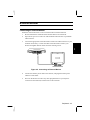
1
Notice for Users in the USA
FCC Statement
WARNING - FCC Regulations state that any unauthorized changes or modifications
to this equipment not expressly approved by the manufacturer could void the user’s
authority to operate this equipment.
Note: This equipment has been tested and found to comply with the limits for a Class
B digital device pursuant to Part 15 of the FCC Rules.
These limits are designed to provide reasonable protection against harmful
interference in a residential installation. This equipment generates, uses and can
radiate radio frequency energy and, if not installed and used in accordance with the
instructions, may cause harmful interference to radio communications. However,
there is no guarantee that interference will not occur in a particular installation. If
this equipment does cause harmful interference to radio or television reception,
which can be determined by turning the equipment off and on, the user is encouraged
to try to correct the interference by one or more of the following measures:
•
•
•
Reorient or relocate the receiving antenna.
Increase the distance between the equipment and receiver.
Connect the equipment into an outlet on a circuit different from that to which the
receiver is connected.
• Consult the dealer or an experienced radio / TV technician for help.
A shielded I/F cable is required to insure compliance with FCC regulation for Class
B computing equipment.
* As an Energy Star Partner, SHARP has determined that this product meets the
Energy Star guidelines for energy efficiency.
Declaration of Conformity
SHARP PERSONAL COMPUTER, PC-W100 Series
This device complies with part 15 of the FCC rules. Operation is subject to the following
conditions:(1)this device may not cause harmful interference, and (2) this device must
accept any interference recieved, including interference that may cause undesired
operation.
Responsible Party:
SHARP ELECTRONICS CORPORATION
Sharp Plaza, Mahwah, New Jersey 07430
TEL: 1-800-BE-SHARP
i
About the Modem
This equipment PC-W100 Series complies with Part 68 of FCC rules. On the bottom
of this equipment is a label that contains, among other information, the FCC
registration number and ringer equivalence number (REN) for this equipment. If
requested, this information must be provided to the telephone company.
The modem jack of this equipment complies with Sub-part F of Part 68 of FCC
rules.
The REN is used to determine the quantity of devices which may be connected to the
telephone line. Excessive RENs on the telephone line may result in the devices not
ringing in response to an incoming call. In most, but not all areas, the sum of the
RENs should not exceed five (5.0). To be certain of the number of devices that may
be connected to the line, as determined by the total RENs contact the telephone
company to determine the maximum REN for the calling areas.
If the terminal equipment causes harm to the telephone network, the telephone
company will notify you in advance that temporary discontinuance of service may be
required. But if advance notice isn't practical, the telephone company will notify the
customer as soon as possible. Also, you will be advised of your right to file a
compliant with the FCC if you believe it necessary.
The telephone company may mark changes in its facilities, equipment, operations, or
procedures that could affect the operation of the equipment. If this happens, the
telephone company will provide advance notice in order for you to make the
necessary modifications in order to maintain uninterrupted service.
If trouble is experience with this equipment, please contact Sharp Electronics Corp.
for repair and (or) warranty information (Refer to the end of this section). If the
trouble is causing harm to the telephone network, the telephone company may
request you remove the equipment from the network until the problem is resolved.
The equipment cannot be used on public coin service provided by the telephone
company. Connection to Party Line Service is subject to state tariffs. (Contact the
state public utility commission, public service commission or corporation
commission for information.)
ii
The Telephone Consumer Protection Act of 1991 marks it unlawful for any person to
use a computer or other electronic device, including fax machines, to send any
message unless such message clearly contains in a margin at the top or bottom of
each transmitted page or on the first page of the transmission, the date and time it is
sent and an identification of the business or other entity, or other individual sending
the message and the telephone number of the sending machine or such business,
other entity, or individual. (The telephone number provided may not be a 900
number or any other number for which charges exceed local or long-distance
transmission charges.) To program this information, refer to the manual of the
communication software.
CAUTION
Danger of explosion if battery is incorrectly replaced. Replace only with the same or
equivalent type recommended by the manufacturer. Discard used batteries according
to the manufacturer's instructions.
Copyright
It is the intent of Sharp that this product be used in full compliance with the
copyright laws of the United States and that prior permission be obtained from
copyright owners whenever necessary.
Product Information and Customer Assistance
For Product Information and Customer Assistance:
Call: 1-800-BE-SHARP (237-4277)
Sharp Electronics Corp.
Sharp Plaza
Mahwah, NJ
07430
iii
Notice for Users in Canada
About Modem
The Load Number of your modem is 6.
The Industry Canada label identifies certified equipment.
This certification means that the equipment meet certain telecommunications
network protective, operational and safety requirements. The department does not
guarantee the equipment will operate to the user's satisfaction.
Before installing this equipment, users should ensure that it is permissible to be
connected to the facilites of the local telecommunications company.
The equipment must also be installed using an acceptable method of connection. In
some cases, the company's inside writing associated with a single line individual
service may be extended by means of a certified connector assembly (telephone
extension cord). The customer should be aware that compliance with the above
conditions may not prevent degradation of service in some situations.
Repairs to certified equipment should be made by an authorized Canadian
maintenance facility designated by the supplier. Any repairs or alterations made by
the user to this equipment, or equipment malfunctions, may give the
telecommunications company cause to request the user to disconnect the equipment.
Users should ensure for their own protection that the electrical ground connections
of the power utility, telephone lines and internal metallic water pipe system, if
present, are connected together. This precaution may be particularly important in
rural areas.
CAUTION Users should not attempt to make such connections themselves, but
should contact the approprlate electric inspection authrity, or electrician, as
appropriate.
iv
“The Load Number (LN) assigned to each terminal device denotes the percentage
of the total load to be connected to a telephone loop which is used by the device. To
prevent overloading, the termination on a loop may consist of any combination of
devise subject only to the requirement that the total of the Load Numbers of all the
devices does not exceed 100.”
This digital apparatus does not exceed the Class A Limits for radio noise emissions
from digital apparatus as set out in the Radio Interference Regulation of the
Canadian Department to Communications.
Product Information and Customer Assistance
For Product Information and Customer Assistance:
Call: 1-905-890-2100
Sharp Electronics of Canada Ltd.
335 Britannia Road East,
Mississauga, Ontario, L4Z 1W9
Canada
v
Notice for Users in Australia
Service Inquiries
Please contact your dealer for service if required or contact Sharp Corporation of
Australia on 1-800-807820 (free call) for referral to your nearest Sharp authorised
Service Centre. Details can be found on the warranty card inserted with the
documentation.
CAUTION
Danger of explosion if battery is incorrectly replaced. Replace only with the same or
equivalent type recommended by the manufacturer. Do not dispose of large
quantities of used Lithium batteries at the same time.
Copyright
Copyright may exist in material you wish to record. Copying or broadcasting such
material without permission of the relevant licensees or owners of the copyright is
prohibited by law.
SHARP is not in a position to authorise the copying or broadcasting of copyright
materials and nothing in this OPERATION MANUAL should be implied as giving
that authority.
vi
Notice for Users in the UK
IMPORTANT
The wires in this mains lead are coloured in accordance with the following code:
BLUE:
Neutral
BROWN: Live
As the colours of the wires in the mains lead of this apparatus may not
correspond with the coloured markings identifying the terminals in your plug
proceed as follows.
The wire which is coloured BLUE must be connected to the terminal which is
marked with the letter N or coloured black.
The wire which is coloured BROWN must be connected to the terminal which
is marked with the letter L or coloured red.
This apparatus must be protected by a 3A fuse in the mains plug or
distribution board.
“WARNING: THIS APPARATUS MUST BE EARTHED”
This apparatus is approved under approval number NS/G 1234/J/100003 for indirect
connection to the public telecommunication system in the United Kingdom.
Copyright
Recording and playback of any material may require consent, which SHARP is
unable to give. Please refer particularly to the provisions of the Copyright Act 1956,
the Dramatic and Musical Performers Protection Act 1958, the Performers
Protection Acts 1963 and 1972 and to any subsequent statutory enactments and
orders.
vii
Notice for Users in Europe
This equipment complies with the requirements of Directives
89/336/EEC and 73/23/EEC as amended by 93/68/EEC.
Dieses Gerät entspricht den Anforderungen der EG-Richtlinien
89/336/EWG und 73/23/EWG mit Änderung 93/68/EWG.
Ce matériel répond aux exigences contenues dans les directives
89/336/CEE et 73/23/CEE modifiées par la directive 93/68/CEE.
Dit apparaat voldoet aan de eisen van de richtlijnen 89/336/EEG en
73/23/EEG, gewijzigd door 93/68/EEG.
Dette udstyr overholder kravene i direktiv nr. 89/336/EEC og
73/23/EEC med tillæg nr. 93/68/EEC.
Quest' apparecchio è conforme ai requisiti delle direttive 89/336/EEC e
73/23/EEC, come emendata dalla direttiva 93/68/EEC.
´
´
´
´
Η εγκατασταση
αυτη ´ανταποκρινεται
στιζ απαιτησειζ
των οδηγιων τηζ
´
Ευρωπαïκηζ Ενωσηζ 89/336/EOK κατ 73/23/EOK, óπωζ οι κανονισµοι
´
´
´
αυτοι συµπληρωθηκαν
απó την
οδηγια 93/68/EOK.´
Este equipamento obedece às exigências das directivas 89/336/CEE e
73/23/CEE, na sua versão corrigida pela directiva 93/68/CEE.
Este aparato satisface las exigencias de las Directivas 89/336/CEE y
73/23/CEE, modificadas por medio de la 93/68/CEE.
Denna utrustning uppfyller kraven enligt riktlinjerna 89/336/EEC och
73/23/EEC så som komplette ras av 93/68/EEC.
Dette produktet oppfyller betingelsene i direktivene 89/336/EEC og
73/23/EEC i endringen 93/68/EEC.
Tämä laite täyttää direktiivien 89/336/EEC ja 73/23/EEC vaatimukset,
joita on muutettu direktiivillä 93/68/EEC.
viii
CAUTION:
TO PREVENT ELECTRICAL SHOCK, DISCONNECT THE AC CORD AND
THE BATTERY BEFORE SERVICING.
CAUTION:
FOR A COMPLETE ELECTRICAL DISCONNECTION, PULL OUT THE MAIN
PLUG AND THE BATTERY.
VORSICHT:
UM DIE STROMZUFUHR VOLLSTÄNDIG ZU UNTERBRECHEN, DEN
NETZSTECKER HERAUSZIEHEN UND DIE BATTERIE ÈNTFERNEN.
ATTENTION:
POUR UN ARRET TOTAL DU SYSTEME, DECONNECTEZ LE FIL DE LA
BATTERIE.
VARNING:
FÖR TOTAL ELEKTRISK URKOPPLING, KOPPLA UR KONTAKTEN OCH
TA UR BATTERIET.
PRECAUCION:
PARA UNA COMPLETA DESCONEXION ELECTRICA DESENCHUFE LA
CLAVIJA DE LA RED Y LA BATERIA.
ix
Safety Precautions
•
•
•
•
•
•
•
•
•
•
x
When locating the notebook, slots and openings are provided for ventilation. To
protect the notebook from over heating, these openings must not be blocked or
covered.
Follow all cautions and instructions which may be marked on the notebook.
Except as described elsewhere in this manual, refer all servicing to qualified
personnel. Immediately shut off the notebook and refer for servicing under the
following conditions:
• when the power cord or plug is damaged or frayed
• if liquid has been spilled on the notebook
• if the notebook has been dropped or the cabinet has been damaged
Never push any objects of any kind into cabinet openings. They may touch
dangerous voltage points or short parts that could result in fire or electrical shock.
Turn off the notebook before installing or removing a peripheral device.
Turn off the notebook and disconnect the AC cord before cleaning.
Do not expose the notebook to direct sunlight.
Keep the notebook away from any magnetic devices and TVs.
Do not drop the notebook.
Since this product is not waterproof, do not use it or store it where fluids, for
example water, can splash onto it. Raindrops, water spray, juice, coffee, steam,
perspiration, etc. will also cause malfunction.
Battery Precautions
Handling
•
•
•
•
•
•
•
•
Never put the battery pack in a fire, as it could explode and cause injury.
Do not attempt to open or alter the battery pack.
Do not place the battery where it might get hotter than 60°C (140°F).
Do not allow metal objects such as jewelry to short across the battery terminals, as
it could heat up and explode.
The battery includes a circuit breaker to help protect against short circuiting.
However, covering or pressing this breaker switch hard could cause the battery to
malfunction.
Do not allow liquids to come in contact with the battery pack.
Avoid dropping the pack, or other violent shock.
Do not solder to the battery terminals.
Charging
•
Charge the battery pack only with the notebook’s built-in AC adapter.
Discharging
•
Do not use the battery pack for any purpose other than powering the notebook
computer.
Storage
•
•
Store the battery pack in a cool and dry place. Never allow the temperature to
exceed 60°C (140°F) during storage.
Recharge the battery pack after storage, before use.
xi
About This Manual
Notice
Information in this manual is subject to change without notice and does not represent a
commitment on the part of Sharp Corporation.
Sharp Corporation shall not be liable for technical or editorial errors or omissions contained
herein; nor for incidental or consequential damages resulting from the furnishing,
performance, or use of this material.
Sharp strongly recommends that separate permanent written records be kept of all important
data. Data may be lost or altered in virtually any electronic memory product under certain
circumstances. Therefore, Sharp assumes no responsibility for data lost or otherwise rendered
unusable whether as a result of improper use, repairs, defects, battery replacement, use after
the specified battery life has expired, or any other causes.
Sharp assumes no responsibility directly or indirectly, for financial losses or claims from
third persons resulting from the use of this product and any of its functions, such as stolen
credit card numbers, the loss of or alteration of stored data, etc.
Edition
1st Edition, August 1996.
Copyright
© 1996 Sharp Corporation
This document contains or refers to proprietary information which is protected by copyright. All rights
are reserved. Copying or other reproduction of this document is prohibited without the prior written
permission of Sharp Corporation.
Trademarks
Pentium is a registered trademark of Intel Corporation.
IBM and PS/2 are trademarks of International Business Machines Corporation.
IntelliLink is a registered trademark of IntelliLink Corporation.
Microsoft, MS-DOS, Windows, and the Windows Logo are registered trademarks of Microsoft
Corporation.
GlidePoint is a registered trademark of Cirque Corporation.
Sound Blaster is a trademark of Creative Technology Ltd.
TranXit is a trademark of Puma Technology.
Netscape Navigator is a trademark of Netscape Communications Corporation.
SuperVoice is a trademark of Pacific Image Communications, Incorporated.
PC-cillin ‘95 Virus Scanner is a registered trademark of Trend Micro Devices, Incorporated.
All other brand and product names are trademarks or registered trademarks of their respective holders.
xii
Recording Important Information
For future reference, please record the following information in the spaces provided
below.
Model Number:
Serial Number:
BIOS Version
Number:
Date of purchase:
Dealer’s Name:
Place of purchase:
Password:
The serial number is printed on a sticker located on the bottom of the notebook. You
will see the BIOS Version number on the middle line of the LCD screen when you
turn on the notebook.
xiii
Contents
Chapter 1
Quick Setup
Provides step-by-step instructions to help you setup and begin using the notebook as
quickly as possible. You should read this chapter first before you do any operations.
Chapter 2
Basic Operations
Explains the basic operations of power sources, GlidePoint, keyboard, online help
and floppy disks,
Chapter 3
Power Management and Battery
Describes how to effectively manage power and use the battery packs.
Chapter 4
Peripherals
Provides detailed instructions on expanding the capabilities of the notebook. Topics
cover printer, external monitor, keyboard/mouse, and audio equipment.
Chapter 5
Communication Functions
Discusses the infrared communication and the modem.
Chapter 6
Hardware Expansion
Describes using PCMCIA cards and increasing memory.
Chapter 7
Using the Passwords
Discusses how to use the password to protect data stored in your notebook.
Chapter 8
Setup Utilities
Describes how to run the Setup Utility to change system settings.
Appendixes
Provides advice on the routine care and maintenance of the notebook, application
notes, self test, system mapping, pin assignment, and technical specifications.
Troubleshooting
Guides you in troubleshooting problems that may arise in the use of the notebook.
xiv
Manual Conventions
Throughout this manual we have used a set of style conventions. These conventions
are described below.
Keyboard Keys
Key labels, when referred to in the instructions, are shown in boldface as below:
Press Enter to continue.
When more than one key are pressed simultaneously, the key labels are separated by
a plus (+) sign, as shown below:
Restart your notebook by pressing Ctrl+Alt+Del.
This means hold down the Ctrl and Alt keys, and press Del simultaneously.
Important key combinations are highlighted throughout this manual by enlarged and
iconic representations of the keys you must press to perform an operation, e.g.,
Fn
F5
Notes and Cautions
Icons and italicized text are used for notes and cautions, to make important
information stand out.
An information icon alerts you to a special technique or information that
may help you perform a task or better understand a process.
A caution icon alerts you to something that may cause problems or
damage to hardware, software or data.
xv
Words/Texts on Screen
Words and texts displayed on the screen, such as window titles or possible
paramenters, are italicized in this manual. For example,
Double-check this icon to display the Power Properties window.
Set the item to Enabled.
Sample Entries/Screens
In the following case, press the Enter key after you type the command.
C:\>FORMAT A: Enter
Note that the screens reproduced in this manual may differ slightly from the screens
you see on your notebook.
File Names
References to commands, utilities, device drivers, directory and file names in this
manual are printed in upper case, as shown below:
Type in the PHDISK command.
Section Titles
Section titles in other parts of the manual are italicized, as shown below:
Refer to Infrared Communication section in Chapter 5.
xvi
CHAPTER
1
Quick Setup
Your notebook is designed and pre-configured for easy setup and use. This chapter
describes the steps you should follow to get up and run the notebook as quickly as
possible.You should read this chapter first.
Connecting to AC Power
The notebook can be powered by either the rechargeable battery pack or AC adapter.
See the next chapter for more information on power sources. The first time you use
the notebook, be sure to perform the steps below:
1.
Make sure the notebook is turned off.
2.
Connect the AC adapter cord to the notebook. (À)
3.
Connect the AC power cord to the AC adapter. (Á)
• Always use the AC adapter supplied with the notebook (EA-W100V).
Using other AC adapters may damage the notebook.
• Always hold the AC adapter cord by its plug.
4.
Plug the AC power cord into a wall outlet. (Â)
Figure 1-1. Connecting to AC Power
Before using the battery pack, be sure to initialize and fully charge it.
Quick Setup 1-1
1
Opening the Notebook
1
At the front of the notebook you will find a locking latch at the front end of the
screen cover. The latch locks the cover in the closed position when the notebook is
not in use. To raise the cover follow these steps:
1.
Slide the display lock latch until the screen cover releases, and then raise the
cover.
2.
Tilt the cover to a comfortable viewing position.
Figure 1-2. Opening the Screen Cover
1-2 Opening the Notebook
Turning Power On
To turn on the power following these steps:
1.
1
Connect the notebook to AC Power.
When using the notebook the first time, be sure to connect it to an AC
power. If you use the battery instead, the Windows 95 setup may not be
able to finish when the battery does not have enough power.
2.
3.
Open the screen cover.
Press the power switch.
Power Switch
Figure 1-3. Turning Power On
• While "Starting Windows 95..." appears, pressing F8 allows you to
choose how to start Windows 95. For details see the Windows 95
documentation as well as the Windows 95 Help files.
• Do not turn power off immediately after turning it on. Instead, wait
several seconds.
When the power is turned on, the power indicator ( ) lights and the notebook goes
through a self test to detect any problems. When this is completed, Windows 95
starts. The first time you use the notebook the Windows 95 Setup screen appears to
guide you to set up Windows 95 properly.
Figure 1-4. Windows 95 Setup
Quick Setup 1-3
Making Adjustments
1
You can adjust the screen brightness and sound volume to provide confortable
usage while operating the notebook.
Adjusting the Screen Brightness
decreases the screen brightness.
increases the screen brightness.
turns the LCD backlighting on or off.
Adjusting Sound Volume
Use the audio volume control (on the right side of the notebook) to adjust the
speaker volume. Turn it away from you to increase the volume, or towards you to
decrease the volume.
1-4 Making Adjustments
Setting up Windows 95
The first screen lets you know what is happening by the following steps:
•
•
•
Gathering information
Configuring your computer
Restarting your computer
It takes approx. 20 minutes to complete all of the Setup procedures.
1.
Regional Settings Many Windows programs support international settings.
These settings affect how these programs display and sort numbers, currency,
the time and the date. Select the regional setting that most closely matches
where you live. The default is English (American).
2.
Keyboard Layout Select the keyboard. The default is United States.
3.
User Information Enter your name, and if you like, the name of your company.
4.
Windows 95 License The screen displays the license of Windows 95. Proceed
to the next screen by clicking Next.
5.
License Agreement Read the license agreement displayed in the screen. Click I
accept the agreement if you accept. Then click Next.
6.
Certificate of Authenticity See the Certificate of Authenticity on the front
cover of the Microsoft Windows 95 manual which came with your notebook.
Type the number shown above the bar code on your Certificate of Authenticity,
and then click Next to continue.
7.
Configuring the Computer Now Setup has enough information to start
configuring your notebook. If you want to review or change any settings, click
the Back button. If you want to continue, click Next. Setup will configure your
notebook. This process may take several minutes.
8.
Finishing Setup Setup has finished configuring your notebook and is ready to
restart, to load the just-configured Windows 95. Click the Finish button and
then the OK button to restart your notebook. The notebook restarts.
9.
The Windows 95 Setup wallpaper appears. It may take several minutes to detect
your hardware.
10. The items which Setup is configuring are automatically displayed one by one.
Quick Setup 1-5
1
1
11. Set Up Printer You must select a printer before you can print from Windows.
Click the manufacture and model of your printer. If your printer is not listed,
consult your printer documentation for a compatible printer. Then select the
port you want to use with this printer, and then click Next. All your Windowsbased programs will use this printer as the default printer.
12. Print a test page After your printer is installed, Windows can print a test page
so you can confirm that the printer is set up properly. Then, Setup installs the
printer driver which is appropriate for the selected printer.
13. Time Zone Select the time zone where you are.
All the Setup procedures of Windows 95 are now complete.
1-6 Setting up Windows 95
Creating the Setup Disks
The notebook proceeds to the next step "Microsoft Create System Disks ".
This program backs up most of the pre-installed software including Windows 95 on
your hard disk by creating Setup disks. These disks will help protect your software
investment. They can be used to reinstall Windows 95 and other software on your
hard disk in case of the following:
•
•
If the contents of your hard disk are accidentally damaged in any way
If you need to recreate the suspend-to-disk partition in the hard disk
• These Setup Disks serve as a backup for your factory installed
software. If you experience a problem and do not have these disks, you
may not be able to recover your system or personal data.
• We strongly recommend that you use high quality floppy disks and
store these disks in a secure place.
Creating System and Application Disks
Creating disks for Windows 95 and pre-installed applications
Application floppy disks generated by MSCSD (Microsoft Create System Disks) are
as follows.
• Microsoft Windows 95 Setup Disks
31 disks
•
•
•
•
•
•
•
•
•
•
•
•
•
Netscape Navigator Setup Disks
3 disks
Zrlink Setup Disk
1 disk
Sharp Import/Export Setup Disks
2 disks
TranXit Setup Disks
2 disks
Super Voice Setup Disks
2 disks
PC-cillin ‘95 Scanner Setup Disk
1 disk
Power Panel Setup Disks
2 disks
Audio Driver Setup Disks
4 disks
Windows 95 S3 Driver Disk
1 disk
ALPS GlidePoint Driver Disk
1 disk
Sharp Support Disk
2 disks; Driver, Utility
Sharp Data Disk
1 disk; Online Manual,
Windows 95 Startup Disk
1 disk
54 disks total
Quick Setup 1-7
1
Microsoft Windows 95 Setup Disks Use to restore Windows 95 from disks if the
software is damaged on your computer.
1
Netscape Navigator Setup Disks Use to restore Netscape Navigator program for
accessing to the Internet.
Zrlink Setup Disks Use to restore Sharp ZR link program for communicating with
the Sharp electronic organizer.
Sharp Import/Export Setup Disks Use to restore Sharp Import/Export program for
communicating with the Sharp electronic organizer.
TranXit Setup Disks Use to restore TranXit program for transferring files between
Pcs.
Super Voice Setup Disks(U.S. and Canada only) Use to restore Super Voice program
for voice/fax/data communication.
PC-cillin ‘95 Scanner Setup Disk Use to restore PC-cillin ‘95 Scanner program for
virus scanning.
PowerPanel Setup Disk Use to restore Phoenix PowerPanel program for managing
the power management.
Audio Driver Setup Disks Use to restore audio driver appropriate for your notebook.
Windows 95 S3 Driver Disk Use to restore S3 display driver.
ALPS GlidePoint Driver Disk Use to restore ALPS GlidePoint Driver.
Sharp Support Disks Use to restore the GlidePoint Control utility, Infrared driver,
and PCM+3.2 PCMCIA Card driver for MS-DOS.
Sharp Data Disk Use to restore the Sharp Online Manual and wallpaper data.
Windows 95 Startup Disk Windows 95 Startup Disk can be used to start up the
notebook if the notebook cannot start for any reason. The Disk starts up the
notebook and displays A:\> prompt.
You can choose not to create system disks this time by clicking Cancel. Until you
create all the system disks, Windows 95 will remind you at startup to do so. Select
the counter. If the counter is set to 5, you'll be reminded every 5th time you start
Windows. To prevent this warning from appearing again, set the counter to 0. You
also have an option to create the Setup Disks by clicking Programs, accessories,
Systems Tools, then Create System Disks.
1-8 Creating the Setup Disks
You can choose one of the items from the lists for creating the Setup Disks, then
follow the on-screen prompt to create all the Setup Disks.You can use the lables
provided in the shrinks pack of the Windows 95 manual to label the 31 pcs of
Windows 95 Setup Disks, but the labels of the other Setup Disks are not provided
with your notebook. After you completed to make all the Setup Disks except the
Windows 95 Startup Disk, you will see the dialog box to finish creating system disks,
then click Finish and the Microsoft Create System Disks will appear nowhere.
Windows 95 Startup Disk can be made from the Control Panel. From the Control
Panel, double-click Add/Remove Programs. Then click the Startup Disk tab then
Create Disk.
Quick Setup 1-9
1
Setting Initial Condition
1
After setting up Windows 95, you need to set the initial condition of this notebook
in the following procedure.
1.
Double-click the Sharp Startup icon at the upper right corner of the screen.
2.
When the message appears, click OK.
The next time the computer is restarted, several programs are set in the StartUp
folder, and the SHARP original wallpaper is displayed on the screen as default.
The instructions in the documents attached to the notebook assume that
you have set the initial condition.
1-10 Setting Initial Condition
Shutting Down the System
To power off the notebook, from the Start menu, select Shut Down and then click
Yes. The notebook turns off automatically.
If a file is not saved yet, then a dialog box will appear asking you if you
want to save it or not.
• While the hard disk or floppy disk drive indicator is lit, do not turn off
the power or reset the notebook. Doing so may damage or even wipe
out the data.
• To protect the screen, always close the screen cover when the power is
turned off.
• Before turning it back on, wait at least 10 seconds after turning off the
notebook. Turning the power off and on in rapid succession can
damage the notebook’s electrical circuitry.
Quick Setup 1-11
1
Resetting the System
1
Software Reset
You can reset the software if you encounter software problems which lock up the
notebook. To reset the system or “reboot,” press the Ctrl+Alt+Del keys
simultaneously. Then, follow the instructions on the screen: press the Ctrl+Alt+Del
keys again. The notebook restarts. This is known as a “warm boot.”
Resetting may cause data loss. Use the software reset only if the normal
Windows 95 Shut Down does not work because of software malfunction.
Although resetting will not damage the system, you may lose the data
you are processing.
Power Switch
You can turn off the notebook with the power switch if you encounter hardware or
software problems which lock up the system. Press the power switch for more than
five seconds. The notebook will shut down.
Hardware Reset
You should use the hardware reset switch only if the power switch does not turn off
the notebook. The switch is in the small hole at the bottom of the notebook. Press
this switch with the tip of a pencil or ballpoint pen. The notebook will shut down.
Before turning it back on, wait at least 10 seconds after turning off the
notebook. Turning the power off and on in rapid succession can damage
the notebook’s electrical circuitry.
1-12 Resetting the System
CHAPTER
Basic Operations
This chapter describes the basic operations you can perform on the notebook.
2
Choosing a Power Source
The notebook is designed to operate with one of the following power sources:
•
•
AC power from a wall outlet
Lithium-ion battery pack
Use AC power whenever possible, relying on the battery pack only when AC power
is unavailable.
About the Power Indicator (
)
The power indicator shows the power status of your notebook.
Power Indicator
On
Blinking
Off
Meaning
Power is on.
The notebook is in Suspend to RAM mode.
The notebook is in Suspend to Disk mode or the
power is off.
For more information, see Chapter 3 on Suspend to RAM and Suspend to
Disk modes.
Using the AC Adapter
The AC adapter provides power for operation and to charge the battery when the AC
adapter is connected to a wall outlet. The AC input voltage can range anywhere from
100 to 240 volts, making it suitable for use virtually anywhere in the world with the
appropriate plug adapter.
The AC power cord provided with the notebook is appropriate for the
voltage of your local area. If you attempt to connect the notebook to a
wall outlet other than your local area, check the voltage of the outlet
and use an AC power cord appropriate for the outlet.
Basic Operations 2-1
2
Using the Battery Pack
The rechargeable lithium-ion battery pack allows you to operate the notebook
without an external power source. When fully charged, a battery pack can supply
power to your notebook for up to 2 hours; much longer periods of time may be
possible if the notebook’s advanced power management features have been
activated.
2
The amount of time a battery charge will last will depend on the
notebook usage. Applications which heavily use the peripherals, like
the floppy disk drive, will experience shorter power on time.
Initializing the Battery Pack
The first time you use the battery pack, be sure to initialize it, as follows:
1.
Turn on the notebook without connecting it to the AC adapter. Use the
notebook until it beeps to indicate that it is fully discharged and shuts down
automatically.
2.
Connect the notebook to the AC adapter and fully charge the battery pack.
• In step 1, if the notebook does not function even after you plug in into
a wall outlet, this means the battery pack is not charged yet. Simply
proceed to step 2 immediately.
• Also, if "Press <F1> to resume, <F2> to SETUP" appears after the
notebook is turned on, this means the setup contents have changed.
Press F2, then press Enter. When the Setup Utility screen appears,
press Esc, then Enter twice to restart the system again.
Charging the Battery
To recharge the battery, connect the AC adapter to the notebook as described in the
previous section and turn off the notebook. Approximately 3 hours are required to
fully charge a low battery. The battery indicator lights in orange while the battery is
charging. The indicator flashing in orange in the recharge may indicate some trouble.
Disconnect the notebook, remove the battery pack, re-insert it, and connect the
notebook to the AC adapter again. If the indicator still flickers, the system has a
problem.
• If you have not used the notebook for a long time, the battery may
become completely discharged. In such a case, recharging will take
more time than usual.
• If you use the notebook for a while, the battery will become hot. The
notebook starts recharging after returning a normal temperature.
2-2 Choosing a Power Source
About the Battery Indicator (
)
The battery indicator shows you the status of the battery pack.
Battery
Indicator
On (green)
On (orange)
Blinking
(orange)
On (red)
Operating
Environment
AC power or
battery
AC power
AC power or
battery
Battery
Blinking (red)
Status
The battery pack is fully charged.
The battery pack is being charged.
An error has occurred.
The battery power will last for only few
more minutes.
The warning beeps continues for 10
seconds.
The battery power is almost gone.
The warning beeps continues while the
notebook automatically enters the
suspend-to-disk mode.
Checking the Battery Level
Check the battery level as follows:
1.
From the Start menu, select Control Panel.
2.
Double-click Power and read the battery level.
• The remaining battery amount and remaining time are estimates based
upon calculated values. Depending on the actual usage, the
remaining time may be shorter than that indicated.
• However, if the remaining time is significantly shorter than that
indicated, re-initialize the battery.
Basic Operations 2-3
2
2
Low Battery Indication
When your notebook senses that the battery only has enough charge to continue
for a few minutes, it will alert you to a low battery condition by blinking red the
battery indicator and sounding a battery low warning beep. The remaining operating
time depends on the power you are consuming: if you are using the audio system,
PCMCIA slot or hard and floppy disk drives, your notebook might run out of charge
very quickly. You should always respond to the battery low indication by
connecting to AC power or turning off your notebook, or suspending your notebook
to disk. If you do not do so, the notebook will automatically suspend to disk
(regardless of the setting of the Suspend Mode option in the Setup Utility) and turn
off. The contents of the memory will be stored in the suspend-to-disk partition. You
will be unable to restart the notebook until you have connected to AC or installed a
fresh, charged battery.
If the notebook is in the Suspend to RAM mode when the battery is
critically low, the notebook will attempt to Suspend to Disk (if enabled
in the Setup Utility), and then turn off.
Maintaining the Battery Pack
You should discharge the battery pack if you do not use the notebook for a long time
and should recharge it fully before use. If the battery is fully charged and left unused
for a long time.
• The battery will discharge itself slowly, and
• The life of the battery will be shortened.
Lithium-ion batteries do not have so-called “memory effect,”and you do
not have to deep discharge the battery pack before charging it.
Disposing of Battery Packs
The capacity of a battery pack is gr
adually decreasing while used repeatedly. Although the deterioration rate depends
on the operating temperature and environments, the pack can sufficiently be used for
500 times, after which you should consider purchasing a replacement battery pack
that is identical to the battery pack.
Your local area may have rules which you should follow regarding battery disposal.
In addition to the main lithium-ion battery, you should remember the small backup
battery located under the keyboard. Bring your notebook to a local dealer for
replacement of this backup battery if your notebook begins to lose its time and date
setting.
Backup batteries
The notebook has two backup batteries. The rechargeable NiMH battery prevents
loss of data during replacement of the lithium-ion battery while in the suspend mode.
However, this will not work if the battery level of the NiMH battery is low. Therefore,
power-off or suspend to disk is recommended when replacing the lithium-ion battery.
The other backup battery is a non-rechargeable coin type Lithium battery for RTC.
2-4 Choosing a Power Source
Operating the GlidePoint
Your notebook features GlidePoint, an integrated pointing device, connected
internally to a PS/2 port and compatible with the Microsoft Mouse and IBM PS/2
mouse. The GlidePoint combines high resolution fingertip control and an ergonomic
design equally suitable for left-handed and right-handed users. Most software
applications will require use of the “left” button.
• Do not hit or scratch the surface of the GlidPoint with pointed objects
(such as ballpoint pen).
• Do not operate the GlidePoint with wet or sweaty hand; otherwise the
GlidePoint may not operate correctly.
Using the GlidePoint
Take a moment to become familiar with how the GlidePoint works.
Figure 2-1. The Integrated GlidePoint
Place Your Fingertip
Place your left or right hand next to the GlidePoint, resting your wrist naturally in a
relaxed manner. Place your thumb or forefinger on the GlidePoint.
Basic Operations 2-5
2
Move Your Fingertip
The rectangular pad of the GlidePoint acts like a miniature duplicate of your display.
As you slide your fingertip across the pad, the pointer on the screen, moves in the
same direction across the screen as your fingertip moves across the pad. The
GlidePoint is very sensitive and you don’t need to exert much pressure on the pad at
all. You’ll get the best results by sliding your fingertip over the pad very lightly.
2
Point and Click
When you have placed the pointer over the icon, menu item or command that you
wish to execute, you can press the left button once or twice to execute the command.
This procedure is called “point and click” or “point and double-click”. On the
GlidePoint, you can execute point and clicking even more rapidly. Instead of clicking
by pressing the left button, you can just tap gently anywhere on the rectangular pad
of the GlidePoint. Tap twice rapidly to execute a double-click. Unlike a traditional
pointing device, the whole pad acts as if it were a left button and each tap on the pad
is equivalent to pressing the left button.
If you swap the left and right buttons, “tapping” on the GlidePoint as an
alternative method of pressing the left button will no longer function.
Drag and Drop
You can execute commands or move files by using “drag and drop”. In drag and
drop, you activate a file by pointing to it and clicking. However, when you click the
button, you do not release the button but instead hold it down. You can then drag
the active file around the screen by moving your finger around the pad. When you
have placed the file where you want it, for example in a new directory, release the left
button. The file will drop into the new location. You can also do drag and drop
operations using the GlidePoint as a large left button. Position the pointer over the
item that you want to drag. Gently tap twice on the pad. On the second tap, keep
your finger in contact with the pad. You can then drag the selected object around the
screen by moving your fingertip across the pad. When you lift your fingertip from
the pad, the selected object will drop into place.
2-6 Operating the GlidePoint
Understanding the Keyboard Layout
The notebook provides all the functionality of a full-sized desktop 101- or 102-key
keyboard. You should familiarize yourself with the special notebook function
keystrokes which allow you to quickly and easily control and adjust such features as
display brightness and access to power management.
2
Figure 2-2. Keyboard Layouts
Windows Logo Keys
opens the Windows Start menu.
provides application-specific short-cut menu equivalent to the
right button.
Basic Operations 2-7
System Function Keys
The notebook has special system function keys which activate key functions printed
on keys serving dual functions. When pressed in conjunction with the Fn key, these
keys set specific system parameters and are sometimes referred to as “hot keys”.
2
toggles between video display output to the LCD screen,
SimulScan (display on the LCD and external CRT monitor), and
the CRT.
decreases the LCD screen brightness.
increases the LCD screen brightness.
Fn + F8 and Fn + F9 do not function.
turns the screen backlighting on or off.
puts the notebook in suspend mode (to RAM or to Disk,
according to the setup selection). To resume normal operation
from Suspend to RAM, press any key. To resume from Suspend
to Disk, press the power switch.
2-8 Understanding the Keyboard Layout
Using Floppy Disks
Floppy disks used by the notebook are made of magnetic material and enclosed in a
protective plastic case. The case protects the magnetic surface of the disk against
scratches, bending and dust. A shutter on the case opens automatically when
inserted into a floppy disk drive, exposing the disk to the drive's read/write head,
which can then retrieve, record or erase data on the disk's magnetic surface. When
the system attempts to access a floppy disk, the disk starts to spin within its plastic
casing, and the read/write head moves to the proper position on the disk and
performs the operation you requested. You can use double-density (2DD) 720KB or
high-density (2HD) 1.44MB floppy disk.
Handling Floppy Disks
• Do not open the shutter and touch the disk inside; otherwise you will not be able
to read or write data to the disk.
• Do not place floppy disks near magnets and the like, direct sunlight, a heat register,
or in dusty place.
• Do not leave floppy disks on the built-in speakers; the magnets inside the speakers
may destroy the disks.
• Never subject a disk to sudden shocks or extreme vibration. Do not drop it or bend
it. Do not place heavy objects on the disk.
• Do not spill liquid onto the disk.
Write-protecting a Floppy Disk
On the floppy disk is an arrow imprinted on the front upper left corner, and a sliding
write-protect tab on the bottom left corner, as illustrated below. When opened, the
write-protect tab prevents data from being written to, or erased from, the floppy disk.
Figure 2-3. Write-protecting a Floppy Disk
Basic Operations 2-9
2
Connecting the Floppy Disk Drive
Follow these steps to connect a floppy disk drive to the notebook:
2
1.
Make sure the notebook is turned off.
2.
Plug the large connector of the drive into the printer/floppy disk drive
connector on the back of the notebook. Then plug the small connector into the
external keyboard and PS/2 mouse port.
Figure 2-4. Connecting a Floppy Disk Drive
When turned on, the notebook will be able to recognize the floppy disk drive
automatically.
When inserting a floppy disk into the notebook, make sure it is not
upside down. Also, do not subject the disk to sudden shock.
2-10 Using Floppy Disks
Inserting and Removing a Floppy Disk
Inserting
Hold the floppy disk with the arrow facing up and towards the drive. Slide the disk
into the drive until it clicks into place.
2
Figure 2-5. Inserting a Floppy Disk
• Always insert a floppy disk straight into the notebook.
• When inserting the disk into the notebook, make sure it is not upside
down.
• Do not push the disk into the notebook by excessive force.
Removing
Make sure the floppy disk drive indicator is off. Press the eject button to pop out the
disk slightly, then remove it and store it away properly.
Indicator
Figure 2-6. Ejecting a Floppy Disk
Basic Operations 2-11
Formatting a Floppy Disk
2
1.
Connect the floppy disk drive to the notebook, and turn the notebook on.
2.
Make sure the floppy disk is not write-protected, and insert it into the floppy
disk drive.
3.
Double-click My Computer on the desktop.
4.
Click 3 ½ Floppy [A:]. From the File menu, select Format.
5.
From the format drop-down list, select 1.44MB or 720KB.
6.
Click Start to start formatting.
Backing Up Data
If you back up your data regularly, you will have an extra copy of the data to use in
case the original data is damaged or lost. Windows 95 has a backup function to let
you easily back up your data.
From the Start menu, select Programs - Accessories - System Tools - Backup to start
the backup operation. For more information, use the Windows 95 Help.
Backup method may differ depending on software in use.
Windows 95 Startup Disk
You need this disk only when you want to use the notebook if the notebook cannot
start for any reason. It starts up the notebook and displays A:\>prompt. It may be
useful:
•
•
•
when you find your hard disk is damaged and you wish to format your hard disk
by executing the FORMAT command on the Windows 95 Startup Disk.
when Windows is damaged and you wish to re-install it using Windows 95 Setup
Disks.
when you want to recreate the suspend-to disk partition in your hard disk.
2-12 Using Floppy Disks
CHAPTER
3
Power Management and Battery
This chapter explains how to better manage the notebook's power and use additional
battery packs.
Activating Power Management
In addition to superior performance and an enhanced feature set, your notebook
incorporates sophisticated power management features which allow you to extend
battery life. You should think of your notebook’s power conservation features as
being organized into several, sometimes overlapping, levels of management, which
together provide both manual and automatic control over which components of the
notebook are drawing current at any given time.
Changing Power Configuration Settings
You can configure power management settings using the Power menu of the Setup
Utility. Power settings allow you to control current drain by peripheral devices and
put them in suspend mode when not in use. By continually monitoring the state of
these devices, and shutting off the flow of current to idle devices, battery life can be
preserved.
You can access the Power menu of the Setup Utility to set power management
parameters in the following way:
•
Press the F2 key when prompted on screen just after you have turned on or reset
the notebook and before Windows starts. Then press the left or right arrow key to
select Power menu at the top of the Setup Utility screen.
Figure 3-1. Setup Utility Power Configuration Screen
Using Your Notebook 3-1
3
Power Switch Function Selects whether the power switch turns the notebook on
and off (the default), or makes the notebook enter the suspend mode and resume
from it.
Power Management Allows you to enable or disable power management. When
this option is Disabled, all power management settings specified are ignored. When
set to AC Disabled (the default), power management is disabled only when the
notebook is powered by AC.
3
CPU Performance Specifies the CPU performance. High refers to normal
performance. Selecting Low reduces the CPU performance and thus saves power; as
a result, system operation will also slow down.
Hard Disk Power Down after Allows you to specify a period of inactivity after
which the hard disk drive is shut down. Possible values include Disabled, 1 2, 4, 8,
or 16 min (default is 1 min). When the specified time elapses without accessing the
drive, the drive turns off. You will notice a slight delay when a resume event occurs,
while the hard disk drive powers back up.
LCD Backlight Allows you to select the brightness of the LCD Backlight. Possible
values include Bright, Standard, or Dim.
Suspend Mode Allows you to select when a suspend event occurs, Suspend to RAM
(the default) or Suspend to Disk. The exceptions are: the notebook suspends to RAM
for cover switch event and suspends to disk for critical battery event.
Auto Suspend Allows you to specify a period after which the notebook
automatically enters suspend mode. You can set it to 5, 10, 15, 20, 30, 40, 60 min or
Disabled. When the time-out you specify elapses, the notebook becomes inactive; all
device activity is suspended and the processor is powered off. If the Suspend to
RAM feature has been selected, only memory is powered so that stored information
can be retrieved instantly when a resume event occurs. If the Suspend to Disk feature
has been selected, all information in memory is saved to a special partition on the
hard disk drive before the system powers off.
Since Windows 95 periodically accesses the hard disk and automatically
writes to the display, Auto Suspend sometimes does not work.
3-2 Activating Power Management
Auto Suspend to Disk Determines whether or not the notebook suspends to disk if
battery voltage drops to the critical level during Suspend to RAM.
PCMCIA Power when Suspend to RAM Determines whether power is applied to
the PCMCIA slot while the notebook is in the Suspend to RAM state. You can
disable it to save power, but any PCMCIA card will be disabled when a Suspend to
RAM occurs, and may require re-initialization when operation resumes.
Modem Power when Suspend to RAM Determines whether the modem is powered
on during the Suspend to RAM.
Battery Level The % change level of the battery is displayed here.
Suspend Mode
Suspend mode is the lowest power consumption level your notebook can sustain.
Two different suspend modes are Suspend to RAM and Suspend to Disk. As a
default your system is set to Suspend to RAM. You can program the notebook to
suspend to RAM or to disk by using the Suspend Mode option in the Setup Utility.
Suspend to RAM
When the notebook suspends to RAM, an alerting beep sounds, and the state of the
notebook is stored to RAM. All but a few essential components of your notebook
power down. Pressing any key allows the notebook to return to exactly the same
state it was in when suspend mode was activated. You can use Suspend to RAM
when you have to pause your computing but plan to resume working after a short
interval, since operation resumes almost immediately.
The RAM contents are preserved using the AC power supply or the
battery. If all power sources are disconnected while the unit is in Suspend
to RAM mode, the RAM contents will be lost.
Suspend to Disk
You can also configure your notebook to suspend to disk. The system preserves all
the running application programs as a file in a “suspend-to-disk partition” on the
hard disk drive. The notebook then turns off automatically. When you next turn on
the notebook, it reads the file from the suspend-to-disk partition back into memory,
so that your notebook is returned to exactly the same state it was in when you
suspended it.
Using Your Notebook 3-3
3
Suspend to Disk is a very useful feature. People frequently open many applications
and have them iconized on the Windows screen. It takes some time to get all these
applications open and running, and normally they all have to be closed before the
system can be turned off. If you use the Suspend to Disk feature, you don’t need to
close the applications as the state of your notebook is saved to disk. When you next
turn on your notebook, your Windows screen, with all the applications open, will be
recreated in just a few seconds.
• 36MB of your hard disk space has been reserved as the suspend-to-disk
partition when your notebook shipped from the factory. This means you
can safely suspend to disk if the notebook has 32MB of installed
memory.
• When you enter or resume from Suspend to Disk mode, you can see
some flicker on the display. However, this is not a malfunction.
3
Entering Suspend Mode
Suspend mode can be activated in any of the following ways:
•
•
•
•
•
•
By clicking Suspend on the Windows Start menu.
By pressing Fn+F12.
By setting the Auto Suspend option in the Setup Utility to automatically suspend
after a certain period of notebook inactivity. See the section on Changing Power
Configuration Settings for details.
By closing the cover (always suspends to RAM).
By the power switch (if so configured in the Setup Utility).
By low battery voltage. During normal operation, the notebook will suspend to
disk immediately. If it is already suspended to RAM, the data is copied to disk if
the Auto Suspend to Disk setting is enabled in the Setup Utility (otherwise, the
data is lost if the batteries drain completely).
The system does not enter Suspend to Disk or RAM mode when playing
video or animation.
3-4 Activating Power Management
When entering or returning from suspended mode, be sure to observe the
following precautions. Otherwise, the notebook may not operate correctly
after the notebook has resumed from the suspend mode.
• Do not operate the keyboard, Glide Point or mouse in the process of
entering or returning from suspended mode.
• Before activating suspended mode, terminate any optical or modem
communications and make sure that no video or audio playback is in
progress.
• In Windows 95, set the Power Management item to Advanced.
• When using a modem, set the Modem Power when Suspend to RAM
item to Enabled.
• When using a PC Card, set the PCMCIA Power when Suspend to RAM
item to Enabled.
Resuming from Suspend Mode
Normally, resuming from a suspend mode is triggered as follows:
•
•
•
•
By the power switch.
If Suspend to RAM is active, by pressing any key, or by calling up the modem.
Also, if the suspend state was entered by closing the cover, operation resumes
when the cover is opened (as long as battery voltage is sufficient).
However, if the suspend state was caused by the battery capacity dropping below
a certain level, operation can be resumed only after AC power is connected or a
charged battery installed, and then only by the power switch.
When a resume event occurs, the system returns to where it was when suspend mode
was entered, e.g., software applications open, the display reappears, etc.
Using Your Notebook 3-5
3
Using Battery Packs
If you need to operate the notebook on battery for extended period of time, you may
purchase additional battery packs (CE-W10EB) as the same type as the bundled
battery pack with the notebook.
Replacing a Battery Pack
Use the following steps to replace a battery pack:
1.
Turn off the notebook and disconnect the AC adapter as well as any peripherals
in use.
2.
Close the screen cover. Place the notebook on a flat surface, then turn it upside
down so that the front is facing you.
3.
Slide out the two battery locks as shown (➀), then gently lift up the battery
pack (➁).
3
battery lock lever
Figure 3-2. Removing a Battery Pack
4.
Insert another battery pack into the notebook, making sure the four tabs on the
battery pack go right into the grooves of the notebook.
For easy insertion, align the inner two tabs first and then the outer two tabs.
Figure 3-3. Inserting a Battery Pack
3-6 Using Battery Packs
5.
Return the two battery locks to their original positions.
There is a danger of explosion if the battery is incorrectly replaced.
Replace the battery only with Sharp's optional battery packs. Discard
used batteries according to the dealer's instructions.
• When using a new battery pack for the first time, be sure to initialize
and charge it.
• While you can install an optional battery pack into the notebook and
charge it like the standard battery, you can also use the optional
battery charger (CE-W10CH) to charge it. See the section below for
more information.
Using the Battery Charger
You can use the optional battery charger (CE-W10CH) to charge the battery packs.
Installing a battery pack
1.
Insert the 2 inner tabs on the battery pack into the grooves on the battery
charger so that the battery pack clicks into place.
battery charger
Figure 3-4. Installing a battery pack
2.
Use the supplied AC adapter or the optional AC adapter (CE-W100V) to
connect the charger to the wall outlet.
Use the optional AC adapter (CE-W100V) only for the PC-W100 and CEW10CH.
Using Your Notebook 3-7
3
Reading the Indicators
power lamp
battery lamp
Figure 3-5. Indicator on Battery Charger
Power Indicator
3
Meaning
On
The AC adapter is connected.
Off
The AC adapter is not connected.
Battery Indicator
Meaning
On (green)
The battery is fully charged.
On (orange)
Charging
Blinking (orange)
An error occured.
Fully charging a new battery pack takes about three hours.
If the battery indictor blinks in orange, an error has occurred during the
charge. Therefore, remove the battery pack, then replace it again.
Removing the Battery Pack
1.
Unplug the AC adapter from the battery charger.
2.
Push the battery lock on the sides of the charger (➀), then gently lift up the
battery (➁).
Figure 3-6. Removing the Battery Pack
3-8 Using Battery Packs
CHAPTER
4
Peripherals
This chapter describes how to attach optional devices to your notebook. You can
attach a printer, connect an external monitor or keyboard, a mouse, or any other
peripheral device that connects to a parallel, serial or PS/2 keyboard/mouse port.
Printer
The notebook has both a parallel and a serial interface. You can easily connect your
notebook to a printer that has either of these types of interfaces, by following the
instructions below.
Before you begin, read your printer manual, and determine its interface type. If your
printer supports both a parallel and a serial interface, it is recommended that you
configure your printer to use the parallel interface, which is faster and easier. The
notebook’s parallel port supports the latest EPP and ECP parallel port protocols for
improved performance and versatility with compliant printers. However, you need the
special printer drivers to use EPP protocols.
4
Connecting a Printer
To connect a printer to the notebook, follow these steps:
1.
Be sure both the notebook and the printer are turned off.
2.
Open the I/O port cover at the rear of the notebook with your finger and locate
the ports labeled parallel and serial.
3.
If you are using a parallel interface, connect the 25-pin male connector of your
printer cable to the 25-pin female parallel port on your notebook. If you are
using a serial interface, connect the 9-pin female connector of your printer cable
to the 9-pin male serial port on your notebook. Note that if your serial printer
cable is equipped with a 25-pin connector, you will need an adapter that
converts 9-pin serial output to 25-pin output.
Peripherals 4-1
4.
If necessary, attach the other end of your printer cable to your printer, and
tighten any retaining screws. A typical parallel printer connection is illustrated
below.
4
Figure 4-1. Connecting a Printer (Parallel Port)
5.
Power on the printer and any other peripheral devices you may have connected
to the notebook, and then turn on the notebook.
6.
If necessary, run the notebook’s Setup Utility to configure the parallel port to
respond as required by your printer and software operating environment.
Installing the Printer Driver
The newly connected printer must be configured in Windows. Refer to the Windows
95 Help for details on setting up a printer. You can also refer to your printer manual
for instructions on configuring your operating environment and application software
to use the printer.
4-2 Printer
External Monitor
Connecting an External Monitor
Follow the instructions below to use an external monitor with the notebook.
1.
Be sure that both the notebook and the external monitor are turned off.
2.
Open the I/O port cover at the rear of the notebook and locate the 15-pin female
CRT connector.
3.
Connect the appropriate end of the monitor cable to the CRT connector on your
notebook if necessary. Connect the other end of the monitor cable to your
monitor and tighten monitor cable connector retaining screws.
4
Figure 4-2. Connecting an External Monitor
4.
Connect the monitor power cable to the monitor, and plug the monitor power
cable into a wall outlet.
5.
Power on the monitor as well as any other peripheral devices you may have
connected to the notebook, and then turn on the notebook.
Peripherals 4-3
Switching Display Output
You can switch the display output by pressing Fn+F5 key combination in the order:
LCD → CRT&LCD → CRT → LCD. For simultaneous display on the CRT and LCD,
use a monitor with 1024 × 768 resolution capability.
When using Fn + F5 keycombination to change the display output, be sure the Power
Management in the Windows 95 Control Panel is set to Advanced.
Changing Resolution and Number of Colors
To change the resolution and the number of colors,
4
1.
From the Start menu, select Setting - Control Panel.
2.
Double-click Display.
3.
Click the Settings tab.
4.
Select the number of the colors in the Color palette, and select the resolution in
Desktop area. Refer to the table on the next page.
5.
Click OK twice.
• You can select High Color (16 bit) or True Color (24 bit) in the Color Palette. High
Color means 64K colors; True Color means 16,770,000 colors. If you select True
Color (24 bit), however, the LCD can display 256K colors.
• If you select True Color, the drawing speed of screen is decreased.
4-4 External Monitor
Resolutions in Windows 95
Source resolution
256 Colors
High Color
1024×768
1024x768
dots
1024×600
1024x600
dots
800×600
800x600
dots
640×480
CRT only
1024×600
1024×768
*2
256 Colors
High Color
True Color
256 Colors
High Color
True Color
*1
When
FULLSCR
utility is
loaded
640x480
dots
LCD only
Simultaneous display
LCD display
CRT display
1024×600
1024×768
*2
1024×600
1024×600
1024×600
1024×600
800×600
800×600
800×600
800×600
1000×600
800×600
1000×600
800×600
Expanded
display
256 Colors
High Color
True Color
640×480
*1
When
FULLSCR
utility is
loaded
960×600
Expanded
display
4
Expanded
display
640×480
640×480
640×480
640×480
640×480
960×600
Expanded
display
*1
For details regarding the FULLSCR utility, please refer to page 4-7.
*2
Out of 1024 × 768 dots, 1024 × 600 dots are displayed, and the image scrolls up
or down when the mouse cursor is moved to the top or bottom of the screen.
When set to a resolution other than 1024 × 600,
the internal display and an external CRT can be used simultaneously
only if the color is set to 256 colors.
Peripherals 4-5
Resolutions in MS-DOS
In the MS-DOS environment, simultaneous display is possible only if a
multiscan type monitor is used.
Graphic mode
Source resolution
640×350
LCD only
640×350
CRT only
640×350
Simultaneous display
LCD display
CRT display
640×350
640×350
960×525
960×525
Expanded
display
Expanded
display
640×400
640×400
960×600
960×600
640x350 dots
graphic mode
4
*
When
FULLSCR
utility is
loaded
640×400
960×525
640×350
Expanded
display
640×400
640×400
640x400 dots
graphic mode
*
When
FULLSCR
utility is
loaded
640×480
960×600
640×400
Expanded
display
640×480
Expanded
display
640×480
Expanded
display
640×480
640×480
960×600
960×600
640x480 dots
graphic mode
*
When
FULLSCR
utility is
loaded
960×600
Expanded
display
640×480
Expanded
display
* For details regarding the FULLSCR utility, please refer to page 4-7.
4-6 External Monitor
Expanded
display
Text mode
Source resolution
640×350
640x350 dots
text mode
720×350
720x350 dots
text mode
640×400
LCD only
960×525
960×600
Expanded display
720×400
960×600
720x400 dots
text mode
Expanded display
960×525
960×525
Expanded display
Expanded display
960×525
960×525
Expanded display
Expanded display
960×600
960×600
Expanded display
Expanded display
960×600
960×600
Expanded display
Expanded display
720×350
Expanded display
640x400 dots
text mode
*1
640×350
Expanded display
960×525
Simultaneous display
LCD display
CRT display
CRT only
640×400
720×400
For details regarding the FULLSCR utility, please refer to page 4-7.
Switching screen mode
If you have set the screen resolution to 800 × 600 dots, 640 × 480 dots, etc., you can
use the supplied utility to switch between standard screen and full screen, as
follows:
Switching between full screen and standard screen display
Use Notepad or another text editor to add the line in AUTOEXEC.BAT as shown
below. Then reboot the computer.
To use full screen display (load the FULLSCR utility)
C:\WINDOWS\FULLSCR.COM
To use standard screen display (load the ORGSCR utility)
C:\WINDOWS\ORGSCR.COM
Peripherals 4-7
4
Keyboard/Mouse
Connecting a Keyboard or PS/2 Mouse
If you wish to use a full size desktop keyboard or external PS/2 mouse with your
notebook, follow the instructions below.
1.
Be sure that the notebook is turned off.
2.
Locate the PS/2 keyboard/mouse port on the rear of the notebook.
3.
Attach the PS/2 cable from your mouse or keyboard cable to the PS/2
keyboard/mouse port, as illustrated below.
4
Figure 4-3. Connecting an External Keyboard or PS/2 Mouse
4.
Power on any other peripheral devices you may have connected to the
notebook, and then turn on the notebook.
Never connect or disconnect PS/2 devices to the PS/2 keyboard/mouse
port when the notebook is powered on. This may cause the notebook to
operate improperly.
4-8 Keyboard/Mouse
Disabling the GlidePoint
When connecting a mouse to your notebook, you can disable the GlidePoint in the
following steps:
1.
Make sure the mouse is enabled before disabling the GlidePoint. If the mouse is
not enabled, the cursor does not move when you move the mouse.
2.
From the Start menu, select SHARP Applications - GlidePoint Control.
3.
Select Disables GlidePoint.
4.
Click OK.
If the Glide Point was disabled when entering suspended mode, it will be
enabled after returning from suspended mode.
4
Connecting a Serial Mouse
1.
Turn off the notebook.
2.
Locate the RS-232C serial port (
3.
Plug the serial mouse into the RS-232C serial port.
).
Figure 4-4. Connecting a Serial Mouse
4.
Turn on the notebook.
5.
From the Start menu, select Settings - Control Panel.
6.
Double-click Mouse.
7.
Click the General Tab, then click Change.
8.
Select the manufacturer and model name, then click OK. Click Close.
9.
Click Yes and the notebook will restart again.
When the serial mouse is active, the GlidePoint cannot be used.
Peripherals 4-9
Audio Equipment
You can connect the notebook to an audio equipment, using the steps below.
1.
Turn off the power to the notebook as well as any connected peripherals.
2.
Use the following audio cable for the connection:
To output the notebook’s audio signal to the audio equipment:
4
To input audio signal from the audio equipment to the notebook:
Figure 4-5. Connecting Audio Equipment
Precautions on Using the Microphone
When using the internal microphone
• Before recording, be sure to turn on AGC (Automatic Gain Control) as
explained on the following page, and reduce the speaker volume to prevent
howling caused by feedback.
• During playback, avoid feedback by turning off AGC and lowering the
microphone volume or muting the microphone.
When using an external microphone
• Be sure to activate AGC as explained on the following page. Variables such as
AGC operation, microphone volume, and microphone muting are controlled
using the audio utility provided with Windows 95.
4-10 Audio Equipment
AGC Control Procedure
1.
From the Start menu, select Programs - Accessories - Multimedia - Volume
Control.
2.
Select Options - Properties.
3.
Select Recording in Adjust volume for and check Microphone in Show the
following volume controls: if it is not checked.
4.
Click OK.
5.
If you do not see the Advanced button, check Advanced Controls in the
Options menu. The Advanced button appears.
6.
Click the Advanced button.
7.
Check 1 Microphone Gain Control.
8.
Click Close.
• The above procedure switches the AGC on. To turn off the AGC, uncheck 1
Microphone Gain Control in the step 7.
Peripherals 4-11
4
CHAPTER
Communication Functions
This chapter explains how to use the infrared communication and the built-in
modem.
5
Infrared Communication
Using the IR port located on the right side of your notebook, you can wirelessly
communicate with ifrared-equipped devices such as a Sharp electronic organizer,
computers or printers. Refer to the manual or online help of each application for the
detail.
Positioning and Preparing the Notebook and the Target Device
Before you establish wireless communication, both the notebook and the target
device should be properly positioned. Locate your notebook in a flat place and then
place the target device so that their IR ports are in line and within approximately 30
inches (80 cm) of each other.
When using a Sharp electronic organizer, make sure they are within 15
inches (40 cm) apart.
5
Setting for Each Application
You need to set the IR type for each communication application.
IR Type
Windows 95 IrDA
Communication
TranXit (Variable mode)
IrDA
Disabled
ZR-PL0
ASK
Disabled
Import/Export
ASK
Disabled
Windows 95 Communication Application
(Direct Cable Connection, etc.)
IrDA
Enabled
Application
To adjust IR type,
1.
From the Start menu, select Settings - Control Panel.
2.
Double-click the IR type icon.
3.
Select the appropriate IR type (ASK or IrDA).
4.
Click OK.
Do not use the Setup Utility to adjust the IR type.
Communication Functions 5-1
Enabling or Disabling Windows 95 IrDA Communication
Windows 95 IrDA communication is disabled by default. To enable it,
1.
From the Start menu, select Settings - Control Panel.
2.
Double-click Infrared.
3.
Select Options.
4.
Check the item of Enable infrared communication on.
5.
Click OK.
Using Communication Applications in Windows 95
Your notebook assigns the physical IR port to COM2 while Windows 95 assigns the
logical IR port to COM4 as default. To use Windows 95 communication applications
such as the Direct Cable Connection, you need to select COM4 for the logical IR
port in the application. Refer to Windows Help for details.
5
When Performing Infrared Communication
If you use a communications application to perform infrared communications, be
sure to use the Setup Utility to disable the Power Management setting.
Do not enter Suspend Mode during the communication session.
Data communication may not function correctly if the power
management is active during the communication session.
5-2 Infrared Communication
Modem
You can use the modem built into your notebook, for data transfer, fax communication and
voice communication.
The internal modem is available in the U.S. and Canada only.
Connecting the Modem to Telephone Line
1.
Connect one end of the included modem cable to the modem jack on the left
side of your notebook.
2.
Connect another end of the cable to the telephone line.
5
Figure 5-1. Connecting to telephone Line
Communication Functions 5-3
Setting Modem Port
To use communication software,
1.
Turn on your notebook.
2.
Press the F2 key when the message Press <F2> to enter Setup appears.
3.
On the Advanced page of the Setup Utility, set the COM1/COM2 Function to
FAX Modem/IR or Serial Port/FAX Modem.
4.
If you assign the modem to COM1, set the COM1 Port to 3F8, IRQ4. If you
assign the modem to COM2, set the COM2 Port to 2F8, IRQ3.
5.
Press the Esc key and select Save Changes & Exit.
6.
In the communication software, set the items such as COM ports, baud rate, etc.
Refer to the software manual or online help or the manual of Windows 95.
Using communications software
5
Before starting to use communications software, set Power Management item in the
Power in the Control Panel to Off. Also, do not enter suspended mode while using
communications software.
If a power management function becomes active during communication,
correct data transfer may not be possible.
You must set parameters such as modem speed (baud rate) and line type (pulse
dialing or tone dialing) within the communications software you are using. For
details, please refer to the documentation of the software.
5-4 Modem
CHAPTER
Hardware Expansion
This chapter describes how to handle PCMCIA cards and increase memory of the
notebook.
6
PCMCIA Cards
Your notebook is equipped with two PCMCIA slots which can accommodate two
Type II or one Type III card conforming to the standards of the PCMCIA (Personal
Computer Memory Card International Association). The slots accept a variety of
PCMCIA cards. Some examples of PCMCIA cards are:
•
•
•
•
•
•
Fax/Modem Card A device that connects the notebook to the telephone line for
use as a fax and/or a modem (although one is already built in).
Network Interface Card A device that connects the notebook to a local area
network (LAN).
SCSI Interface Card A device that enables you to connect SCSI devices such as
MO drives, CD-ROM drives and scanners to your notebook through a SCSI
connector on the SCSI card.
Sound Card A device for sound recording and playback features (although one is
already built in).
ATA Device An AT Attachment, rotating or solid-state mass-storage device that
works like an IDE hard disk drive. An ATA device does not require an external
power source to maintain data when removed from the notebook’s PCMCIA slot.
SRAM Memory Card A static RAM memory device that can be formatted as a
diskette, with a write-protect switch on the edge of the card. An on-card battery
maintains the data when it is removed from the notebook’s PCMCIA slot.
Hardware Expansion 6-1
6
Inserting and Ejecting PCMCIA Cards
PC Cards are inserted and ejected in much the same way as floppy disks. The upper
and lower slots both accept Type II cards. Therefore, you can insert up to two Type
II cards at the same time. For Type III card, use the lower slot. When a Type III card
is inserted, the upper slot cannot be used.
Note that some PCMCIA memory cards must be formatted before you can use them
for data storage; see your PCMCIA card manual for details.
1.
Open the PCMCIA card compartment cover on the right side of the notebook.
(You do not have to power off the notebook to handle PCMCIA cards when
using Windows 95.)
2.
Align the card with the appropriate slot and slide the card into the slot until it
locks into place. The top of the card is identified by the manufacturer’s label.
The upper slot is identified as Socket 2, and the lower slot is identified as
Socket 1.
6
Figure 6-1. Inserting and Ejecting PCMCIA Cards
3.
To eject a PCMCIA card, click the PCMCIA Card Control icon on the taskbar,
then the Stop button to stop using the PCMCIA card. Use a pointed object
(such as a ballpoint pen) to press the appropriate eject button to pop out the
card. Then remove the card and store it away properly.
6-2 PCMCIA Cards
Installing the PCMCIA Card Driver
When you insert a PCMCIA card into the notebook, the driver for the card will
usually be installed automatically. If automatic installation is not possible, a dialog
box will appear so that you can follow its instructions to complete the installation.
Some PCMCIA cards use the COM3 or COM4 port which may conflict
with the COM1 or COM2 port already used by other devices in the
notebook. If your PCMCIA card uses COM3, set the COM1 Port: option
in the Setup Utility to Disabled. If the card uses COM4, set the COM2
Port: option or IR Type: to Disabled.
6
Hardware Expansion 6-3
Memory Module
The notebook comes standard with 16MB of memory, but you can add another
16MB to obtain a total of 32MB of memory. See the following sections on how to
install a memory module (CE-W102B).
Installing a Memory Module
• Do not handle a component at a place where static electricity is easily
generated, such as on the carpet.
• Before installing a memory module, carefully discharge static
electricity from your body by touching an unpainted metal area.
• Avoid touching the integrated circuits on a memory module. Handle all
components by the edges.
• Keep a memory module in the anti-static wrapping until you are ready
to install it.
Follow the steps below to install a memory module:
6
1.
Turn off the notebook and unplug the AC adapter.
2.
Slide out the locking knobs on either side of the notebook as illustrated, then
lift up the keyboard.
Figure 6-2. Lifting Up the Keyboard
6-4 Memory Module
3.
Remove the memory module from its wrapping.
4.
Hold the memory module so that its edge connector is facing the socket. Make
sure the notch on the corner of the memory module mates with the notch on the
socket.
Figure 6-3. Securing the Memory Module
5.
Insert the memory module into the socket and gently push it until it is firmly
seated (➀).
6.
Slowly move the memory module to a horizontal position until the locking tabs
snap into the retaining notches or holes at each end of the module (➁).
7.
Replace the keyboard and push back the locking knobs.
Removing a Memory Module
Follow the steps below to remove a memory module:
1.
Turn off the notebook and unplug the AC adapter.
2.
Open the keyboard as described in the previous section.
3.
Remove the locking tabs from the memory module at the same time until the
memory module comes out of the notches. Gently move the memory module
upward and remove it.
Figure 4. Removing the Memory Module
Hardware Expansion 6-5
6
4.
Replace the keyboard and push back the locking knobs.
Store the memory module in an anti-static wrapping or other conductive
shield such as aluminum foil.
6
6-6 Memory Module
Appendixes
The appendixes which follow contain additional and more advanced information on
the use and care of your notebook as well as detailed technical specifications.
Care and Maintenance
This appendix provides you with information on how to maintain the notebook in top
working condition.
Travel
The notebook is designed for portability. For safety and convenience when
traveling, please follow these guidelines.
•
•
•
•
•
•
Before traveling, save your data by backing it up onto diskettes.
Take along an extra backup copy of your data.
Do not travel with a diskette in the drive.
Do not travel with the notebook powered on. This may result in loss of data
and/or damage to the hard disk drive.
Disconnect the AC adapter from the notebook.
Take along a spare, fully charged battery pack, or AC cord.
When carrying the notebook, take care not to bump it into things.
Appendixes A-1
Maintenance
The notebook requires little physical maintenance. As with any piece of electrical
equipment, however, you should follow a few simple maintenance routines and
precautions so that your notebook can provide outstanding performance for many
years to come.
•
•
•
•
•
•
•
Check the AC power cord and power connectors periodically for damage. Replace
the power cord immediately if damage is found.
Keep your notebook away from rain, snow, excessive humidity, direct sunlight,
high temperatures, and extreme cold.
Do not smoke near your notebook.
Do not eat or drink near your notebook to avoid spillage.
Try to avoid dusty environments since dust can cause damage to your disks and
drives.
Never subject your notebook to sudden shocks or extreme vibration. Do not drop
it or hit it with other equipment.
If you suddenly move your notebook from a cold place to a warm place,
undesirable moisture may condense inside the unit. After sudden temperature
changes, allow the notebook to come to room temperature before you begin using
it. This allows any moisture inside the notebook to evaporate.
The LCD Screen
•
•
•
•
Avoid scratching the surface of the screen.
Do not leave water droplets on the screen. Water can cause permanent staining.
Do not expose the LCD screen to bright sunlight or ultra-violet radiation.
Do not expose the LCD screen to extreme temperatures. Freezing and liquefaction
of the liquid crystals may result in damage to the display.
A-2 Care and Maintenance
Cleaning the Notebook
Cabinet
Apply a small amount of mild cleaning solution to a dry, lint-free cloth and wipe the
cabinet with the cloth.
• Do not use alcohol, benzene, thinner or other strong chemical agents
that may damage the cabinet.
• Never clean the notebook while it is powered on.
Screen
The surface of the screen may become smeared and accumulate dust during use. Try
not to touch the screen with your fingers when using the system. Apply a small
amount of dilute neutral detergent to a dry, lint-free cloth, and gently rub the surface
of the screen with the cloth.
IR Port
Always keep the IR port clean, as dust on the port will interfere with data transfer.
Use a soft, dry cloth to wipe the IR port.
GlidePoint
Use a soft, dry cloth to wipe the GlidePoint.
Appendixes A-3
Suspend-to-Disk Partition
The suspend-to-disk partition is an area of the hard disk reserved for the suspend-todisk operation. When suspend-to-disk operation activates, information in the
memory is saved in this area and restored into the memory when the notebook is
turned on again.
If you change the partition of the hard disk, you must also create the suspend-todisk partition again.
Changing the size of the suspend-to-disk partition will destroy data on
the hard disk. Therefore, do not change the partition size unless
necessary.
About the Suspend-to-Disk Partition Size
When you create a suspend-to-disk partition, make it the amount of the memory plus
4MB. The extra 4MB allows for the overhead of the program and data held in video
memory.
When shipped, the notebook comes with 36MB of suspend-to-disk partition.
Use the following table to determine the size of the partition required.
Memory Size
16MB
32MB
A-4 Suspend-to-Disk Partition
Partition Size
20MB (20480KB)
36MB (36864KB)
Recreating the Suspend-to-Disk Partition
Carefully follow the steps below to create a new suspend-to-disk partition. Since
creating a new suspend-to-disk partition destroys all the data on the hard disk, you
must first backup all the data on the hard disk drive.
The entire procedure includes the following steps:
•
•
•
•
•
Backing up all the data of the hard disk
Deleting the current suspend-to-disk partition
Deleting the partition that contains current files
Creating the new suspend-to-disk partition
Restoring the system
You should prepare the following items:
•
•
•
Windows 95 Setup Disks.
Windows 95 Startup Disk.
Two or more boxes of 1.44 MB diskettes, depending on how much you have used
your hard disk.
Backing up all the data of the hard disk
1.
2.
3.
From the Start menu, select Help.
Open the topic on Backup.
Start Backup from the Help windows.
Deleting the current suspend-to-disk partition
1.
2.
3.
4.
5.
6.
7.
Insert the Windows 95 Startup Disk into the floppy disk drive.
Reboot the notebook.
Press F2 when the message Press <F2> to enter SETUP appears.
On the Main page of Setup Utility, set Boot Sequence to A: Then C:.
On the Security page, set Hard disk boot sector to Normal.
Press the Esc key and select Save Changes & Exit.
When the system restarts, the following message appears:
Do you want to set up Windows 95?
(To change the suspend-to-disk partition, select N.)
[Y/N]
Appendixes A-5
8.
9.
Press the N key. A:\> prompt appears.
Type PHDISK /DELETE /PARTITION and press Enter.
Deleting the partition that contains current files
Following the above steps,
1. Type FDISK and press Enter.
2. Select 3. Delete partition or Logical DOS Drive and press Enter.
3. Select 1. Delete Primary DOS Partition and press Enter.
4. Press the Enter key, input the volume label and press the Enter key again.
5. Press the Y key and then the Enter key.
6. Press the Esc key twice.
7. Press the Ctrl+Alt+Del keys simultaneously to restart the system.
8. Press the N key.
Creating the new suspend-to-disk partition
At the A:\> prompt, type PHDISK /CREATE /PARTITION and press Enter.
Creating the new suspend-to-disk partition
The size of the suspend-to-disk partition is automatically defined as the
total of the current memory size and extra 4 MB. If expanding the
memory size after creating the suspend-to-disk partition, you should
recreate the partition to renew its size.
Restoring the System
1.
2.
3.
4.
Re-install Windows 95, consulting Re-installation Instructions.
Restore the backup data according to Windows Help.
On the Main page of Setup Utility, set Boot Sequence back to C: Then A:.
On the Security page, set Hard disk boot sector back to Write protect.
A-6 Suspend-to-Disk Partition
Power-On Self Test
The notebook performs the Power-On Self Test (POST) every time you turn on or
reset the notebook. The POST is a series of system checks that verifies the correct
operation of your notebook's hardware.
If the POST detects a critical error (e.g., a system board failure), the notebook will halt
and generate an audible alarm. If a failure is detected in an area other than the system
board (such as the keyboard), a non-critical error message is displayed on the screen
and testing is stopped. You can continue testing when a non-critical error occurs by
pressing F1.
When the POST encounters an error that requires you to correct something, either a
beep code will sound or a message will be displayed in a box in the middle of the
screen. If you need to enter the Setup Utility to correct a problem press F2.
Otherwise, press F1 to continue the boot process and ignore the error.
Appendixes A-7
System Mapping
You can check the IRQ, I/O port address, DMA, and memory usage, as follows:
1.
From the Start menu, select Settings - Control Panel.
2.
Double-click System.
3.
Select the Device Manager tab.
4.
Click Properties.
5.
Click the item you want to check.
A-8 System Mapping
Pin Assignment
Parallel Port
(25-pin D-SUB Female End)
Pin
Printer
1
2
3
4
5
6
7
8
9
10
11
12
13
14
15
16
17
18• 23
*24
25
Strobe
PData0
PData1
PData2
PData3
PData4
PData5
PData6
PData7
Ack
Busy
PE
Select
Autofd
Error
Init
Selectin
GND
PNF=GND
GND
When FDD is
connected
INDEX
TRK0
WP
RDATA
DSKCHG
MSEN0
DRATE0
MSEN1
DR1
MTR1
WDATA
WGATE
DENSEL
HDSEL
DIR
STEP
GND
PNF=+5V
GND
* PNF=GND: Printer
PNF=+5V: when FDD is connected
Appendixes A-9
RS-232C Serial Port
(9-Pin D-SUB Male End)
Pin
1
2
3
4
5
Signal
DCD
RD
SD
DTR
GND
Pin
6
7
8
9
Signal
DSR
RTS
CTS
RI
External Monitor
(3-Row 15-Pin D-SUB Female End)
Pin
1
2
3
4
5
6
7
8
A-10 Pin Assignment
Signal
Red
Green
Blue
NC
GND
R-RTN
G-RTN
B-RTN
Pin
9
10
11
12
13
14
15
Signal
NC
GND
NC
SDA
HSYNC
VSYNC
SCL
External Keyboard and PS/2 Mouse Port
(6-Pin Mini DIN Female End)
Pin
1
2
3
Signal
KBDATA/MSDAT
A
NC
GND
Pin
4
Signal
VCC
5
6
KBCLOCK/MSCLK
NC
Appendixes A-11
Specifications
Notebook
Parts
CPU
Secondary cache
ROM
RAM
System
Display
Video
Screen
Video Controller
Graphics
LCD
CRT
Calendar/Clock
Keyboard Pointing device
Drive
Floppy disk
Hard disk *1
Interface
Audio
Modem (US only)
PCMCIA slot
Power supply
Battery life *2
Power consumption
Operating
Temperature
environment Humidity
Storage
Temperature
environment Humidity
Dimensions
Weight
Specification
Pentium 133 Mhz 16KB cache memory, math co-processor
256KB (synchronize pipburst SRAM)
IPL, BIOS, selfcheck, Setup Utility, 256KB for VGA BIOS
16MB EDO RAM standard, expandable to 32MB SO-DIMM
slot, 16MB RAM board option
2MB
11.2" TFT Active Matrix color LCD panel
VGA/SVGA (S3 86CM65 controller)
640 × 480 dots max. 256K colors
800 × 600 dots max. 256K colors
1024 × 600 dots max. 256K colors
1024 × 768 dots max. 64K colors *3
640 × 480 dots max. 16.77 million colors
800 × 600 dots max. 16.77 million colors
1024 × 600 dots max. 16.77 million colors
1024 × 768 dots max. 64K colors
Built-in (battery backup)
Windows 95 83/84 keyboard
GlidePoint (touch-sensitive control pad) with 2 buttons
3.5", 1.44MB
1GB enhanced IDE interface (PCI bus)
Printer, RS232C, CRT, PS/2 mouse/keyboard, IR
(IrDA:4Mbps/115Kbps, ASK:9600bps)
Sound Blaster 16 compatible sound board. Built-in microphone
and stereo speakers External microphone jack Stereo input
and output jacks
Fax 14.4Kbps, Data 28.8KBps (voice function)
Type II × 2 or Type III × 1
(PCMCIA Rel 2.1/JEIDA Ver. 4.2 compliant)
AC adapter, Rechargeable lithium-ion battery pack (supplied)
Approx. 2 hours
40W
10°C to 35°C (50°F to 95°F)
20% to 80% (non-condensation)
-20°C to 60°C (-4°F to 140°F)
10% to 90% (non-condensation)
11.61(w) × 7.76(d) × 1.57 (h) inches (295 × 197 × 40 mm)
Approx. 4.6 lbs (2.1 kg), excluding the floppy disk drive
*1: Hard disk capacity is calculated based on 1GB=1,000 × 1,000 × 1,000 bytes. Also, hard disk
capacity may change as a result of design change.
*2: Battery life may vary depending on the power management settings and the application in
use.
A-12 Specifications
*3: Only 1024 × 600 dots can be displayed.
Memory Module (CE-W102B)
Capacity
Dimensions
Weight
16MB EDO RAM
2.66 (w) × 1.11(d) × 0.15 (h) inches
(67.6 × 28.0 × 3.8 mm)
0.02 lbs (9g)
Battery Pack (CE-W10EB)
Type
Capacity
Dimensions
Weight
lithium-ion battery pack
37wh
11.61 (w) × 2.59(d) × 0.99 (h) inches
(295 × 65.9 × 25.2 mm)
0.93 lbs (420g)
Battery Charger (CE-W10CH)
Input
Output
Dimensions
Weight
22V 1.8A
16.4 ± 0.2V/2.6A
5.31 (w) × 3.29(d) × 1.69 (h) inches (135 × 83.5 × 43 mm)
0.28 lbs (125g)
AC Adapter (CE-W100V)
Input
Output
Dimensions
Weight
100 to 240V
22V/1.8A
2.37 (w) × 4.33(d) × 1.14 (h) inches (60 × 110 × 29 mm)
0.51 lbs (230g), excluding AC power cord
Appendixes A-13