1
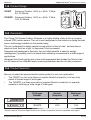
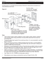
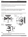
Outdoor Infrascan®
Passive Infrared Motion Sensor
750
Series
Installation Instructions
®
Please leave these instructions at
the installation site.
750 Series
Outdoor Infrascan® Installation Instructions
Table of Contents
1.0
2.0
3.0
4.0
5.0
6.0
7.0
8.0
9.0
10.0
11.0
12.0
13.0
14.0
15.0
16.0
2 of 16
Product Range .................................................................................................3
Description .......................................................................................................3
Product Selection ............................................................................................3
How It Works ....................................................................................................4
Identification Of Parts .....................................................................................5
Installation Location........................................................................................6
Field Of View.....................................................................................................6
Mounting Procedure ........................................................................................7
8.1 Knuckle Adjustments ..................................................................................8
8.2 Wall Mount ..................................................................................................8
8.3 Ceiling Mount ..............................................................................................8
Wiring Diagrams - 750WP 2 Wire Infrascan ..................................................9
Wiring Diagrams - 750WP 2 Wire Infrascan ..................................................9
Commissioning ..............................................................................................11
10.1 Set Up For Walk Test ..............................................................................11
10.2 Time-On Adjustment ...............................................................................11
10.3 Light-Level Adjustment ...........................................................................12
10.4 Sensitivity Adjustment.............................................................................12
Troubleshooting .............................................................................................12
Technical Specifications ...............................................................................13
Warning: Using The 750WP With Special Loads ........................................15
Warranty .........................................................................................................16
Technical Support and Troubleshooting......................................................16
© Clipsal Australia Pty Ltd
Outdoor Infrascan® Installation Instructions
750 Series
1.0 Product Range
750WP
Infrascan Outdoor, 240V a.c, 50Hz, 2-Wire,
5A, 20 Minute
750WPR
Infrascan Outdoor, 240V a.c, 50Hz, 3-Wire,
10A, 20 Minute
2.0 Description
The Clipsal 750 Series Outdoor Infrascan is a highly reliable, state-of-the-art passive
infrared (PIR) motion sensor. The unit is well recognised in the industry as being the best
sensor technology available on the market today.
The unit is designed to detect people moving within its ‘field of view’, and activate an
electrical load, such as a light, in response to that movement.
Designed and developed in Australia, the unit offers benefits in security, energy
management, hospitality and true ‘hands-free’ switching convenience in a wide range of
applications.
Advanced circuit technology and a new multi-segmented lens divides the ‘field of view’
into 48 zones at four different levels, ensuring immediate reaction to body movement.
3.0 Product Selection
Be sure to select the appropriate Infrascan product to suit your application:
•
The 750WP is a two wire (does not require Neutral connection), but can only
switch a limited range of load types.
•
The 750WPR is a three wire device (requires Neutral connection to operate)
capable of switching a wide range of load types.
Catalogue
Number
Neutral
Required
Maximum
Load*
750WP
NO
5A
750WPR
YES
10A
*Please refer to Technical Specifications for further information about compatible load types.
© Clipsal Australia Pty Ltd
3 of 16
750 Series
Outdoor Infrascan® Installation Instructions
4.0 How it Works
With power applied and a suitable load connected, the Infrascan will be able to
detect any moving infrared source (for example, a person that may intrude upon
its ‘field of view’).
The operation of the Infrascan may be set by the user. The unit has three adjustments
on the underside of the sensor head for ‘Light Level’, ‘Time-On’ and ‘Sensitivity’.
The ‘Light-Level’ adjustment activates the load dependent on the ambient light level
in the ‘field of view’ of the sensor. This adjustment can be set to allow the Infrascan to
operate the load at any light level between full daylight and almost complete darkness.
For example, the user can ensure the load is only activated when movement is
detected at night time. During the day time, when there is adequate natural light, the
unit can be set such that it does not activate the load, as it is not necessary to do so.
The ‘Time-On’ adjustment varies the time span that the load will remain on for after
the Infrared source moves out of or stops moving within the ‘field of view’. The load
will automatically be switched off after the ‘Time-On’ period has elapsed. Any period
between 5 seconds and approximately 20 minutes may be set by the time
adjustment screw.
The ‘Sensitivity’ adjustment determines how sensitive the Infrascan becomes.
The more positive the setting, the higher the sensitivity, resulting in a greater
detection range.
Figure 1.
Light Level Threshold adjust
Time-on adjust
Sensitivity adjust
Sensor Head View From Bottom
4 of 16
© Clipsal Australia Pty Ltd
Outdoor Infrascan® Installation Instructions
750 Series
5.0 Identification of Parts
Figure 2.
Sensor head
PIR sensor
window
Mounting base suits
standard (84mm centres)
mounting accessories
-Time
-Light
-Sensitivity
adjustments
Figure 3.
Removable
terminal block
Pilot guides for
drainage holes
Adjustable knuckle
(ball joint and lock
nut combo)
Figure 4.
Note:
•
The sensor head is specially designed to give optimum performance and is
sealed to prevent water or dust from entering the unit. Under no circumstances
should it be tampered with. There are no user serviceable parts inside.
•
Do not apply any pressure on the actual sensor lens itself, as this may damage
the lens, and adversely affect the performance of the unit.
•
Pilot guides may be drilled out to provide drainage when mounting on porous or
uneven surfaces (e.g. brick). Drill out holes only if required, and only on bottom
as mounted.
© Clipsal Australia Pty Ltd
5 of 16
Outdoor Infrascan® Installation Instructions
750 Series
6.0 Installation Location
An Infrascan must be positioned correctly to ensure effective operation. The ‘field of
view’ is optimum when the sensor head is mounted in a vertical position at a height of
2.4 metres and the ‘approach path’ is across the face of the sensor.
Note:
•
Do not mount the Infrascan close to objects which can create rapid temperature
changes e.g. air conditioning vents, heater flues, moving water i.e. fountains and
sprinklers. Avoid locations where condensation is likely to form on the lens.
•
Do not mount the Infrascan on any surface that is subject to movement due to
wind or other causes.
•
In all cases, locate the Infrascan so that the ‘approach path’ is across the ‘field of
view’ and not directly towards the Infrascan.
7.0 Field Of View (At maximum sensitivity)
Figure 5.
Top Elevation
Optimum
‘approach
path’
Ultra short zones
nominal range 1.2m
Short range zones
nominal range 4m
Intermediate zones
nominal range 8m
Long zones
nominal range 18m
Side Elevation
Note:
•
There may be noticeable differences in range due to differing conditions
(background temperature, speed of movement, types of clothing worn, etc).
6 of 16
© Clipsal Australia Pty Ltd
Outdoor Infrascan® Installation Instructions
750 Series
8.0 Mounting Procedure
The Infrascan is mounted as shown below. Electrical connections are made via a
removable terminal block,
Isolation plate
Figure 6.
supplied with 750MBA
mounting base adaptor.
750-GASKET
Mounting gasket (supplied).
Infrascan unit.
Mounting
base.
Mounting
Base
Mounting screws.
Use screws supplied for use with
standard Clipsal 84mm mounting
accessories. Self tapping screws
and wall plug also supplied.
750MBA - Optional
mounting base adaptor
(sold separately). May
be used to mount flood
lamps or run surface
flexible conduit.
Note:
•
The Infrascan sensor head is sealed to protect against water ingress. However,
care must be taken during installation to ensure that water does not enter the
mounting base.
•
To ensure a good seal against the mounting surface, it is recommended to use the
gasket supplied.
•
When mounting on porous or uneven surfaces (such as brick), it may be difficult
to achieve a good seal. In this case the installer may use a silicone or waterproof
sealant to effectively seal the base.
•
Otherwise, it is recommended to drill out the pilot holes provided to allow any water
that may enter the unit to drain out. Note - only drill out the drainage holes on the
bottom of the base, as installed (let water drain out, not in).
•
When mounting on a conductive surface (such as steel framework), it is required to
earth the conductive surface, or else isolate the terminals from that surface in order
to comply with local wiring rules (AS/NZS3000 Australia and New Zealand).
•
Use Clipsal Cat. No. 750MBA mounting base adaptor.
•
Alternatively, mount using a surface block such as Clipsal Cat. No. 238.
© Clipsal Australia Pty Ltd
7 of 16
Outdoor Infrascan® Installation Instructions
750 Series
8.0 Mounting Procedure
Knuckle Adjustments
The Infrascan can be mounted on a vertical or horizontal surface. The unique knuckle
adjustment design incorporates the use of ball joints at each pivot point, enabling the
sensor head to be located in almost any position.
Wall Mount
The sensor head, in the horizontal plane, can be positioned ±90 degrees from the
centre as shown in Figure 7. In the vertical plane, the sensor head can be rotated
upwards 65 degrees and downwards 90 degrees as shown in Figure 8.
Ceiling Mount
The sensor head, in the horizontal plane, can rotate 360 degrees. In the vertical plane,
the sensor head can rotate downwards 90 degrees as shown in Figure 9.
Figure 7.
Figure 8.
Top View
Side View
Figure 9.
Ceiling
Side View
Note:
•
The curve in the knuckle assembly must follow the direction in which the sensor
head is to be directed. Do not try to force the sensor head at any time, check that
the knuckle is correctly aligned.
8 of 16
© Clipsal Australia Pty Ltd
Outdoor Infrascan® Installation Instructions
750 Series
9.0 Wiring Diagrams - 750WP 2 Wire Infrascan
1a). Automatic operation
10A Fuse or MCB
Active/Line
A
Red/Brown
750WP
Load
Load
N
Black/White
1b). Automatic with manual override ON or OFF
Off
10A Fuse or MCB
Active/Line
Red/Brown
750WP
Auto
Load
Load
Black/White
A
Auto
On
N
2x30M or 30MAM
1c). ON, OFF or automatic operation using a 3 position switch
Active/Line
Red/Brown
Auto
10A Fuse or MCB
A
Off
750WP
Load
Black/White
On
39MAOM
Load
N
Note:
•
When switching to AUTO for any of the above configurations the Infrascan will
turn on. Allow 30 seconds plus time-on period for the sensor to stabilise for normal
operation. Wiring diagram 1(a), without override switches is preferred as there is no
settling period.
•
More than one 750WP CANNOT be connected in parallel to a common load. If
parallel connection of multiple devices to control a common load is required, use
Cat. No. 750WPR.
© Clipsal Australia Pty Ltd
9 of 16
Outdoor Infrascan® Installation Instructions
750 Series
10.0 Wiring Diagrams - 750WPR 3 Wire Infrascan
2a) Automatic Operation
10A Fuse or MCB
Active
A
Red/Brown
750WPR
Load
Load
White
Neutral
N
Black/Blue
2b) Automatic with manual override ON or OFF
10A Fuse or MCB
Active
750WPR
Red/Brown
On
Load
A
Auto
White
Neutral
Black/Blue
Off
Load
Auto
N
2x30M or 30MAM
2c) ON, OFF or AUTOMATIC Operation using a 3 position switch
10A Fuse or MCB
Active
On
Red/Brown
750WPR
Load
White
Neutral
Black/Blue
Off
A
Load
Auto
N
39MAOM
Warning:
•
It is illegal for persons other than licensed electricians or persons authorised
by legislation to work on fixed wiring of any electrical installation. Penalties for
conviction are severe.
•
Installation must be carried out in accordance with local wiring rules
(AS/NZS3000 Australia and New Zealand).
10 of 16
© Clipsal Australia Pty Ltd
Outdoor Infrascan® Installation Instructions
750 Series
11.0 Commissioning
When setting the ‘Time-On’ or ‘Light-Level’ or ‘Sensitivity’ adjustments keep clear of the
‘field of view’ when assessing the effect of the adjustment.
11.1 Set Up For Walk Test
The Infrascan can be mounted on a vertical or horizontal surface. The unique knuckle
adjustment design incorporates the use of ball joints at each pivot point, enabling the
sensor head to be located in almost any position.
1
Connect unit to mains power and allow at least 30 seconds for the unit to stabilize
before conducting any tests.
2
Set the ‘Time-On’ adjustment fully anti-clockwise (5 second timer set).
3
Set the ‘Light-Level‘ sensor adjustment fully anti-clockwise (unit set to respond in
light or dark conditions).
4
Set ‘Sensitivity’ adjustment fully clockwise (maximum range set).
5
Remove card from the sensor head and confirm that the load turns on.
Replace card and confirm load turns off after approximately 5 seconds.
6
Loosen the clamp nuts, aim the sensor head towards the desired ‘field of view’.
Tighten clamp nuts and remove card.
7
Walk slowly around the area in the desired ‘field of view’ to confirm the load is
activated from within the desired area.
·Check that the unit responds appropriately when entering the area.
·Check that the unit does not trigger unnecessarily. If necessary, re-aim
the sensor head.
8
Set the ‘Sensitivity’ as desired for required range for normal operation.
9
Set the ‘Light-Level’ as desired for activation at dusk for normal operation.
10
Set the ‘Time-On’ interval to the desired time for normal operation.
5sec
20min
Step 2
Daylight
Darkness
Step 3
Min
Range
Max
Range
Step 4
11.2 Adjustment of ‘Time-On’ and ‘Light-Level’ Settings
Time-On Adjustment
Adjustment Range: five Seconds to 20 Minutes.
Rotate clockwise to set required time-out period.
a
Minimum setting (5 seconds).
b
Set for areas with constant occupation but
infrequent movement.
c
Set for areas with less occupation but constant
movement.
a
b
c
Warning:
•
Take care not to scratch or damage the translucent window on the front of the
Infrascan as it forms part of the optical detection system. For continued optimum
performance ensure that the window is cleaned periodically with mild soap, water
and a soft cloth.
© Clipsal Australia Pty Ltd
11 of 16
Outdoor Infrascan® Installation Instructions
750 Series
11.0 Commissioning
Light-Level Adjustment
Adjustment Range: 1 Lux to full sunlight.
Rotate clockwise to avoid having load activated when natural light is adequate.
a
To activate the load at dusk, set
adjustment to this area.
b
Load activated at night only.
c
Load activated both day and night.
a
b
c
Sensitivity Adjustment
Adjustment Range: 20% - 100% full range. Rotate anti-clockwise to set required
detection range.
a
Maximum detection range.
b
Mid detection range.
c
Minimum detection range.
a
b
c
11.0 Troubleshooting
Problem
Light turns on for no
apparent reason.
Light turns on during
daylight.
Lights do not turn
on in dim and dark
conditions.
Light remains
permanently on.
12 of 16
Possible Cause
Momentary power failure.
Unseen target.
Extreme draughts of hot and cold air.
Trees / bushes moving in the wind.
Vehicular or pedestrian traffic on edge
of ‘field of view’.
Wrong setting on ‘Light Adjustment’.
Possible Action
None, unit will reset after ‘Time-Out’.
Check for animals e.g. dogs/cats etc.
Check doors, windows or air conditioning
outlets.
Re-aim sensor head.
Re-aim sensor head.
Reset according to ‘Commissioning’
Instructions.
Wrong setting on ‘Light Adjustment’.
Reset according to ‘Commissioning’
Instructions.
Light globe blown.
Replace light globe.
Manual override switch fitted and set
Reset according to ‘Commissioning’
to ‘Manual’.
Instructions.
Moving infrared source being detected. Remove unwanted infrared source. If
Note: Do not mount too close to objects unable to resolve, blank off viewing
which can change temperature rapidly window. Light should turn off after ‘Timee.g. air conditioner vents, heater flues, Out’. If light still remains on, call installer.
moving water ie fountains, sprinklers.
© Clipsal Australia Pty Ltd
750 Series
Outdoor Infrascan® Installation Instructions
12.0 Technical Specifications
Catalogue Number
Operating Voltage
750WP
750WPR
200 – 265V 50Hz a.c.
Maximum Load Current
5A
Minimum Load (Watts) *
40W
0W
Maximum Off-State Leakage Current
10mA
0mA
Stand-By Power Consumption
Conductors Required
Neutral Required
Operating Temperature Range
Warm-Up Time
Rated Detection Field at Maximum Sensitivity**
Optimal Mounting Height for Rated Detection Field
Timer Delay Range
Light Level Inhibit Threshold
10A
< 1W
< 1W
2 WIRE
3 WIRE
NO
YES
0° - 50°C
30 seconds
18 metre radius x 110°
2.4 metre with sensor head vertically
oriented
5 Seconds to 20 Minutes,
User Adjustable*****
Continuous from 1 lux to full sunlight, user
adjustable
Mounting Surface
Wall or ceiling mount
(flat surface required)
Mounting Centres
84mm
International Protection Rating***
Cables Accommodated
© Clipsal Australia Pty Ltd
IP66
4 terminals, up to 2 x 2.5mm²
cable per terminal
13 of 16
Outdoor Infrascan® Installation Instructions
750 Series
13.0 Technical Specifications
Catalogue Number
750WP
Compatible Load Types
750WPR
Incandescent
Incandescent
240V Halogen
240V Halogen
Iron Core
Transformers****
Fluorescent
Iron Core Transformers
Electronic Transformers
M
Shaded Pole Induction
Motors (exhaust fans)
(5A Max)
Split Phase Induction
Motors (ceiling fans)
(5A Max)
Other Motor Loads
(Limit to 5A Max)
Incompatible Load
Types
Electronic
Transformers
M
Fluorescent Loads
Discharge Lamps
Motor Loads
N/A
Specifications Typical @ 240V a.c, 25°C
No User Serviceable Parts Inside
This product is recommended for INDOOR or OUTDOOR USE
*
The 750WP 2 Wire Infrascan must be connected to a minimum 40W load, unless the 31CAP
(sold separately) is fitted. Failure to do so may cause unexpected or erratic switching of the load.
**
The range specifications given are based on a 90kg person travelling at greater than one metre
per second across the field of view, where there is a temperature differential greater than five
degrees Celsius between the person and the background. Objects that are hotter or moving
faster (e.g. motor vehicle on nearby roadway) may be detected at greater distances. A person
covered in heavy clothing or walking directly towards the sensor may not be detected until they
get much closer to the unit.
***
The IP66 Protection Rating specified for this product is dependent on the installer to provide an
adequate seal against the mounting surface using the gasket provided.
**** Only iron-core transformers compatible with electronic switches may be used to ensure
compliance with IEC 60669-2-1.
***** Other models are available with longer Time-Out ranges, designated 750Wxx (where xx is the
Time-Out period in minutes).
• 750WPR30 – 30 minute Time-Out
• 750WPR60 – 60 minute Time-Out
14 of 16
© Clipsal Australia Pty Ltd
Outdoor Infrascan® Installation Instructions
750 Series
14.0 Warning: Using the 750WP with Special Loads
Small loads (<40W)
The 750WP product can only drive loads greater than 40W. If you wish to drive a
smaller load, the 31CAP Load Correction Device is required to be fitted in parallel with
the load. For example: when driving a single contactor, be sure to use the 31CAP.
Loads which are sensitive to leakage currents
The 750WP is a two wire device. Two wire devices draw their power through the load. If
this device is used in conjunction with a load which cannot provide enough continuous
load current in the off-state, or the load is sensitive to a high off-state leakage current
(for example: relays, contactors, various loads with built-in electronic control, etc.) a
31CAP Load Correction Device must be connected in parallel with the load.
Small (non-power factor corrected) fluorescent loads
When a 31CAP is fitted, some small non-power factor corrected fluorescent loads
may be controlled using the 750WP. Success varies from manufacturer to
manufacturer. Recommend testing before installation. Installation must be compliant
with local wiring rules.
Line
Neutral
Line
750WP
31CAP
Load
Load
31CAP Load Correction Device
Note:
•
Please note the 750WPR is a three wire device, and switches the load using an
internal relay. Power is not drawn through the load and so the 31CAP is not required.
© Clipsal Australia Pty Ltd
15 of 16
15.0 Warranty
1. The benefits conferred herein are in addition to, and in no way shall be deemed to
derogate; either expressly or by implication, any or all other rights and remedies in
respect to the Clipsal Product, which the consumer has under the Commonwealth
Trade Practices Act or any other similar State or Territory Laws.
2. The warrantor is Clipsal Australia Pty Ltd of 33-37 Port Wakefield Road, Gepps
Cross, South Australia 5094. Telephone (08) 8269 0511. With registered offices in all
Australian States.
3. This Clipsal Product is guaranteed against faulty workmanship and materials for a
period of five (5) years from the date of installation.
4. Clipsal Australia Pty Ltd reserves the right, at its discretion, to either repair free of
parts and labour charges, replace or offer refund in respect to any article found to be
faulty due to materials, parts or workmanship.
5. This warranty is expressly subject to the Clipsal product being installed, wired, tested,
operated and used in accordance with the manufacturer’s instructions.
6. All costs of a claim shall be met by Clipsal Australia Pty Ltd, however should the
product that is the subject of the claim be found to be in good working order all such
costs shall be met by the claimant.
7. When making a claim the consumer shall forward the Clipsal Product to the nearest
office of Clipsal Australia Pty Ltd with adequate particulars of the defect within 28 days
of the fault occurring. The product should be returned securely packed, complete with
details of the date and place of purchase, description of load, and circumstances of
malfunction.
16.0 Technical Support and Troubleshooting
For all technical enquiries and assistance please contact our
National Customer Care Enquiries
Tel 1300 2025 25 (Call cost 25c, number valid within Australia only)
Fax 1300 2025 56
Clipsal Australia Pty Ltd
A member of Schneider Electric
clipsal.com
Contact us: clipsal.com/feedback
Clipsal Australia Pty Ltd reserves the right to change specifications, modify designs and discontinue
items without incurring obligation and whilst every effort is made to ensure that descriptions,
specifications and other information in this catalogue are correct, no warranty is given in respect
thereof and the company shall not be liable for any error therein.
© Clipsal Australia Pty Ltd. The identified trademarks and copyrights are the property of
Clipsal Australia Pty Ltd unless otherwise noted.
F975/11
CLIPCOM 19706 July 2009