1
PPC-150
Pentium® MMX processor-based
panel PC with 15" LCD flat panel
display.
User’s Manual
Copyright Notice
This document is copyrighted, 2000, by Advantech Co. Ltd. All rights are
reserved. Advantech Co., Ltd. reserves the right to alter the products
described in this manual at any time without notice.
No part of this manual may be reproduced, copied, translated or
transmitted in any form or by any means without the prior written
permission of Advantech. Information provided in this manual is intended
to be accurate and reliable. However, Advantech assumes no responsibility
for use of this manual, nor for any infringements upon the rights of third
parties which may result from such use.
All brand and product names mentioned herein are trademarks or
registered trademarks of their respective holders.
Part No. 2002015010
2nd Edition Printed in Taiwan July 2000
ii
FCC Class B
This equipment has been tested and found to comply with the limits for a
Class B digital device, pursuant to Part 15 of the FCC Rules. These limits are
designed to provide reasonable protection against harmful interference when
the equipment is operated in a residential environment. This equipment
generates, uses and can radiate radio frequency energy. If not installed and
used in accordance with this user's manual, it may cause harmful interference
to radio communications. Note that even when this equipment is installed and
used in accordance with this user's manual, there is still no guarantee that
interference will not occur. If this
equipment is believed to be causing harmful interference to radio or television reception, this can be determined by turning the equipment on and off. If
interference is occurring, the user is encouraged to try to correct the interference by one or more of the following measures:
• Reorient or relocate the receiving antenna
• Increase the separation between the equipment and the receiver
• Connect the equipment to a power outlet on a circuit different from that to
which the receiver is connected
• Consult the dealer or an experienced radio/TV technician for help
Warning:
Any changes or modifications made to the equipment
which are not expressly approved by the relevant standards authority could void your authority to operate the
equipment.
iii
Packing List
Before installing your panel PC, ensure that the following materials have
been received:
•
•
•
PPC-150 series panel PC
User's manual
Accessories for PPC-150
- Y-shaped adapter for PS/2 mouse and AT keyboard
- Power cord (1.8 m) - USA type (other types are available on request)
- Floppy disk with CD-ROM drive driver
- "Drivers and Utilities" CD-ROM disc
- Mounting kits and packet of screws
- Heat sink with CPU fan (optional) (refer to Notes 1 and 2)
If any of these items are missing or damaged, contact your distributor or sales
representative immediately.
iv
Note 1:
If the unit you have bought is basic (i.e. without a CPU,
HDD, or SDRAM), you will find this optional item in the
accessory box.
Note 2:
If you install an Intel Pentium® MMX processor yourself,
you must install a heat sink with a CPU fan above the CPU.
This procedure will avoid heat damage to the CPU.
Additional Information and Assistance
1. Visit the Advantech Web sites at www.advantech.com or
www.advantech.com.tw where you can find the latest information about
the product.
2. Contact your distributor, sales representative, or Advantech's customer
service center for technical support if you need additional assistance.
Please have the following information ready before you call:
• Product name and serial number
• Description of your peripheral attachments
• Description of your software (operating system, version, application
software, etc.)
• A complete description of the problem
• The exact wording of any error messages
v
Safety Instructions
1. Read these safety instructions carefully.
2. Keep this User's Manual for later reference.
3. Disconnect this equipment from any AC outlet before cleaning. Use a damp cloth. Do
not use liquid or spray detergents for cleaning.
4. For plug-in equipment, the power outlet socket must be located near the
equipment and must be easily accessible.
5. Keep this equipment away from humidity.
6. Put this equipment on a reliable surface during installation. Dropping it or letting it
fall may cause damage.
7. The openings on the enclosure are for air convection. Protect the equipment from
overheating. DO NOT COVER THE OPENINGS.
8. Make sure the voltage of the power source is correct before connecting the equipment
to the power outlet.
9. Position the power cord so that people cannot step on it. Do not place anything over
the power cord.
10. All cautions and warnings on the equipment should be noted.
11. If the equipment is not used for a long time, disconnect it from the power source to
avoid damage by transient overvoltage.
12. Never pour any liquid into an opening. This may cause fire or electrical shock.
13. Never open the equipment. For safety reasons, the equipment should be opened only
by qualified service personnel.
14. If one of the following situations arises, get the equipment checked by service
personnel:
a. The power cord or plug is damaged.
b. Liquid has penetrated into the equipment.
c. The equipment has been exposed to moisture.
d. The equipment does not work well, or you cannot get it to work according to the
user's manual.
e. The equipment has been dropped and damaged.
f. The equipment has obvious signs of breakage.
15. DO NOT LEAVE THIS EQUIPMENT IN AN UNCONTROLLED
ENVIRONMENT WHERE THE STORAGE TEMPERATURE IS BELOW
-20° C (-4° F) OR ABOVE 60° C (140° F). THIS MAY DAMAGE THE EQUIPMENT.
The sound pressure level at the operator's position according to IEC 704-1:1982 is no
more than 70dB(A).
DISCLAIMER: This set of instructions is given according to IEC 704-1. Advantech
disclaims all responsibility for the accuracy of any statements contained herein.
vi
Wichtige Sicherheishinweise
1.
Bitte lesen sie Sich diese Hinweise sorgfältig durch.
2.
Heben Sie diese Anleitung für den späteren Gebrauch auf.
3.
Vor jedem Reinigen ist das Gerät vom Stromnetz zu trennen. Verwenden Sie
Keine Flüssig-oder Aerosolreiniger. Am besten dient ein angefeuchtetes Tuch zur
Reinigung.
4.
Die NetzanschluBsteckdose soll nahe dem Gerät angebracht und leicht zugänglich
sein.
5.
Das Gerät ist vor Feuchtigkeit zu schützen.
6.
Bei der Aufstellung des Gerätes ist auf sicheren Stand zu achten. Ein Kippen oder
Fallen könnte Verletzungen hervorrufen.
7.
Die Belüftungsöffnungen dienen zur Luftzirkulation die das Gerät vor überhitzung schützt. Sorgen Sie dafür, daB diese Öffnungen nicht abgedeckt werden.
8.
Beachten Sie beim. AnschluB an das Stromnetz die AnschluBwerte.
9.
Verlegen Sie die NetzanschluBleitung so, daB niemand darüber fallen kann. Es
sollte auch nichts auf der Leitung abgestellt werden.
10. Alle Hinweise und Warnungen die sich am Geräten befinden sind zu beachten.
11. Wird das Gerät über einen längeren Zeitraum nicht benutzt, sollten Sie es vom
Stromnetz trennen. Somit wird im Falle einer Überspannung eine
Beschädigung vermieden.
12. Durch die Lüftungsöffnungen dürfen niemals Gegenstände oder Flüssigkeiten in
das Gerät gelangen. Dies könnte einen Brand bzw. elektrischen Schlag auslösen.
13. Öffnen Sie niemals das Gerät. Das Gerät darf aus Gründen der elektrischen
Sicherheit nur von authorisiertem Servicepersonal geöffnet werden.
14. Wenn folgende Situationen auftreten ist das Gerät vom Stromnetz zu trennen und
von einer qualifizierten Servicestelle zu überprüfen:
a - Netzkabel oder Netzstecker sind beschädigt.
b - Flüssigkeit ist in das Gerät eingedrungen.
c - Das Gerät war Feuchtigkeit ausgesetzt.
d - Wenn das Gerät nicht der Bedienungsanleitung entsprechend funktioni
oder Sie mit Hilfe dieser Anleitung keine Verbesserung erzielen.
ert
e - Das Gerät ist gefallen und/oder das Gehäuse ist beschädigt.
f - Wenn das Gerät deutliche Anzeichen eines Defektes aufweist.
Der arbeitsplatzbezogene Schalldruckpegel nach DIN 45 635 Teil 1000
beträgt 70dB(A) oder weiger.
DISCLAIMER: This set of instructions is given according to IEC704-1. Advantech disclaims all
responsibility for the accuracy of any statements contained herein.
vii
Table of Contents
Chapter 1 General Information...........................................1
1.1 Introduction ...................................................................2
1.2 How to Use This Manual ...............................................4
1.3 Specifications ................................................................6
1.4 Dimensions .................................................................10
Chapter 2 System Setup...................................................11
2.1 A Quick Tour of the Panel PC .....................................12
2.2 Preparing For First-time Use .......................................15
2.3 Installation Procedures ...............................................16
2.3.1 Connecting the AC power cord ............................................ 16
2.3.2 Installing the DC Power Insulator
with Hood ..................................................................................... 17
2.3.3 Connecting the keyboard and mouse .................................. 21
2.3.4 Switching on the power ........................................................ 21
2.4 Running the BIOS Setup Program ..............................22
2.5 Installing System Software .........................................22
2.6 Installing the Drivers ...................................................23
Chapter 3 Using the Panel PC..........................................25
3.1 Introduction .................................................................26
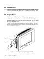
3.2 Floppy Drive ................................................................26
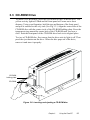
3.3 CD-ROM Drive ............................................................27
3.4 PCMCIA ......................................................................28
3.5 PS/2 Mouse and Keyboard .........................................31
3.6 PCI/ISA Bus Expansion ..............................................31
3.7 Parallel Port ................................................................33
3.8 Serial COM Ports ........................................................33
viii
3.9
3.10
3.11
3.12
3.13
3.14
3.15
VGA Port.....................................................................34
Game Port ..................................................................34
USB Ports ...................................................................34
Audio Interface ............................................................35
Ethernet ......................................................................35
Adjusting the LCD Contrast and Brightness ...............35
Touchscreen (Optional) ..............................................36
Chapter 4 Hardware Installation and Upgrading.............37
4.1 Overview of Hardware Installation and Upgrading ......38
4.2 Disassembling the Panel PC ......................................39
4.3 Installing the 2.5" Hard Disk Drive (HDD) ...................41
4.4 Installing the Central Processing Unit (CPU) ..............42
4.5 Installing the SDRAM Memory Module .......................44
4.6 Installing the Floppy Disk Drive (FDD) ........................44
4.7 Installing the CD-ROM Drive.......................................46
Chapter 5 Jumper Settings and Connectors...................47
5.1 Jumpers and Connectors ............................................48
5.1.1 Setting jumpers .................................................................... 48
5.1.2 Jumpers ............................................................................... 49
5.1.3 Locating jumpers ................................................................. 50
5.1.4 Connectors .......................................................................... 51
5.1.5 Locating connectors ............................................................ 52
5.2 CPU Installation and Upgrading .................................53
5.2.1 System clock setting (JP11, JP8) ........................................ 53
5.2.2 CPU core voltage setting (JP13) ......................................... 55
5.2.3 CPU frequency ratio setting (JP14) ..................................... 58
5.2.4 CMOS clear for external RTC (JP12) .................................. 60
5.2.5 Cyrix linear mode enable (JP10) .......................................... 60
5.2.6 Reset system (JP16) ........................................................... 61
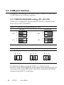
5.3 COM-port Interface .....................................................62
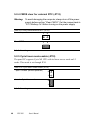
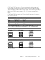
5.3.1 COM2 RS-232/422/485 setting (JP3, JP4, JP5) .................. 62
5.3.2 COM3/COM4/RI pin setting (JP2, JP1) (Reserved) ............. 63
ix
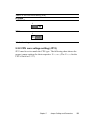
5.4 VGA Interface .............................................................64
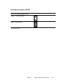
5.4.1 LCD panel power setting (JP6) ............................................ 64
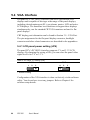
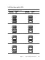
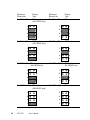
5.4.2 Panel type select (JP9) ........................................................ 65
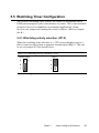
5.5 Watchdog Timer Configuration ...................................67
5.5.1 Watchdog activity selection (JP15) ...................................... 67
Chapter 6 PCI Bus Ethernet Interface..............................69
6.1 Introduction .................................................................70
6.2 Installation of Ethernet Driver .....................................70
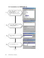
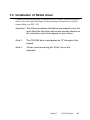
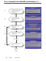
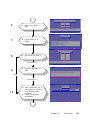
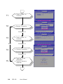
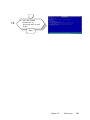
6.2.1 Installation for MS-DOS & WINDOWS 3.1 ........................... 71
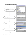
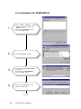
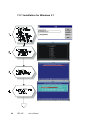
6.2.2 Installation for WINDOWS 95 .............................................. 72
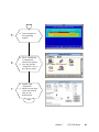
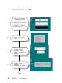
6.2.3 Installation for WINDOWS 98 .............................................. 74
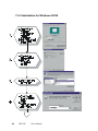
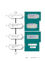
6.2.4 Installation for WINDOWS NT .............................................. 76
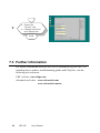
6.3 Further Information .....................................................78
Chapter 7 PCI SVGA Setup...............................................79
7.1 Introduction .................................................................80
7.2 Installation of SVGA driver ..........................................80
7.2.1 Installation for Windows 3.1 ................................................. 82
7.2.2 Installation for Windows 95/98 ............................................. 84
7.2.3 Installation for Windows NT ................................................. 86
7.3 Further Information .....................................................92
Chapter 8 Audio.................................................................93
8.1 Introduction .................................................................94
8.2 Installation of Audio Driver ..........................................94
8.2.1 Installation of MS-DOS ........................................................ 94
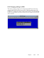
8.2.2 Changing settings in DOS ................................................... 95
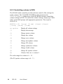
8.2.3 Controlling volume in DOS .................................................. 96
8.2.4 Installation for WINDOWS 3.1 ............................................. 97
8.2.5 Installation for WINDOWS 95/98 ......................................... 98
8.2.6 Installation for WINDOWS NT ............................................ 100
Chapter 9 Award BIOS Setup.........................................103
9.1 Award BIOS Setup ....................................................104
x
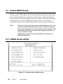
9.2 CMOS Setup Utility ...................................................104
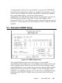
9.3 Standard CMOS Setup .............................................105
9.3.1 Hard Disk Configurations ................................................... 106
9.4
9.5
9.6
9.7
9.8
9.9
9.10
9.11
9.12
9.13
9.14
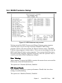
BIOS Features Setup ................................................107
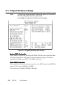
Chipset Features Setup ............................................110
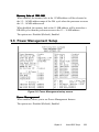
Power Management Setup .......................................111
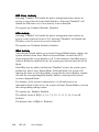
PNP/PCI Configuration Setup ...................................115
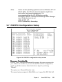
Load BIOS Defaults ..................................................117
Load Setup Defaults .................................................117
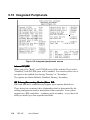
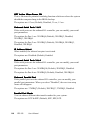
Integrated Peripherals ..............................................118
Password Setting ......................................................121
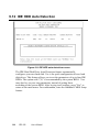
IDE HDD Auto Detection ..........................................122
Save and Exit Setup .................................................123
Exit Without Saving ...................................................123
Chapter 10 Touchscreen.................................................125
10.1 Introduction ...............................................................126
10.1.1 General information ......................................................... 126
10.1.2 Specifications .................................................................. 126
10.1.3 Environmental specifications ........................................... 126
10.2 Installation of Driver for Resistive or SAW .....................
Touchscreen .............................................................127
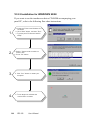
10.2.1 Installation for MS-DOS and Windows 3.1 .............128
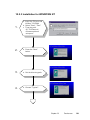
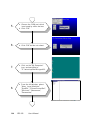
10.2.2 Installation for WINDOWS 95/98 ..................................... 132
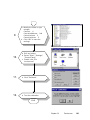
10.2.3 Installation for WINDOWS NT .......................................... 134
10.2.4 Installation for OS/2 (MonitorMouse) ............................... 136
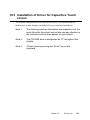
10.3 Installation of Driver for Capacitive Touchscreen .....142
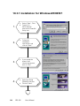
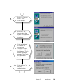
10.3.1 Installation for Windows95/98/NT .................................... 143
Appendix A LCD Specifications and
Selection Settings....................................................145
Appendix B Programming the Watchdog Timer...........147
xi
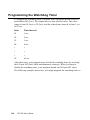
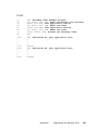
Programming the Watchdog Timer ...........................148
Chapter C Full Disassembly Procedures.......................151
Chapter D Pin Assignments............................................159
IR Connector (J1) (*Reserved) .................................160
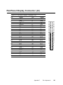
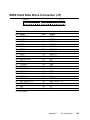
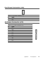
Flat Panel Display Connector (J2) ............................161
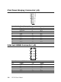
Flat Panel Display Connector (J3) ............................162
Internal COM4 Connector (J4) ..................................162
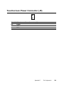
Touchscreen Power Connector (J5) .........................162
Sandisk SSD Connector (J6) ....................................164
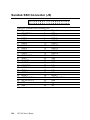
EIDE Hard Disk Drive Connector (J7) .......................164
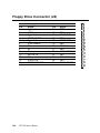
Floppy Drive Connector (J8) .....................................166
CPU Fan Power Connector (J10) .............................166
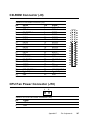
CD-ROM Connector (J9) ..........................................166
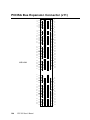
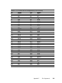
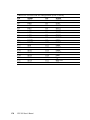
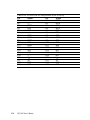
PCI/ISA Bus Expansion Connector (J11) .................168
Fan Power Connector (J12) ......................................172
AT Power Connector (J13) .......................................172
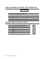
Internal Speaker Connector (J15) (*Reserved) .........174
Inverter Power Connector (J16) ................................174
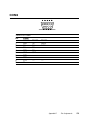
COM2 .......................................................................175
Appendix E Mounting Instructions................................177
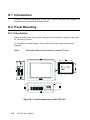
E.1 Introduction ...............................................................178
E.2 Panel Mounting .........................................................178
E.2.1 Introduction ...................................................................... 178
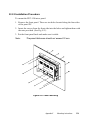
E.2.2 Installation Procedure ....................................................... 179
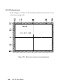
E.2.3 Cut-out area ..................................................................... 180
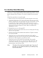
E.3 Desktop Stand Mounting ..........................................181
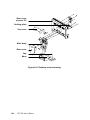
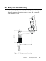
E.4 Swingarm Stand Mounting ........................................183
xii
Tables
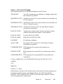
Table 5-1: Jumpers and their functions......................................................49
Table 5-2: Panel PC Connectors...............................................................51
Table 5-3: System/PCI clock setting (JP11) ........................................... 54
Table 5-4: PCI bus clock setting (JP8) .................................................... 55
Table 5-5: CPU voltage setting (JP13) ................................................... 56
Table 5-6: CPU frequency ratio (for Intel) (JP14) .................................... 58
Table 5-7: CPU frequency ratio (for AMD K6, K6-2) (JP14) .................... 59
Table 5-8: Clear CMOS/External RTC (JP12) ........................................ 60
Table 5-9: Cyrix linear mode enable (JP10) ............................................ 60
Table 5-10: Reset system (JP16) ........................................................... 61
Table 5-11: COM2 RS-232/422/485 setting (JP3, JP4) .......................... 62
Table 5-12: COM2 RS-232/422/485 setting (JP5) .................................. 62
Table 5-13: PPC-150 serial port default settings ..................................... 63
Table 5-14: COM4/RI pin setting (JP2) ................................................... 63
Table 5-15: COM3/RI pin setting (JP1) ................................................... 63
Table 5-16: Panel VCC setting (JP6) ...................................................... 64
Table 5-17: Panel type select (JP9) ........................................................ 65
Table 5-18: Watchdog activity selection (JP15) ...................................... 67
Table D-1: IR Connector (J1)..................................................................160
Table D-2:Flat Panel Display Connector (J2)..........................................161
Table D-3: Flat Panel Display (J3)...........................................................162
Table D-4: Internal COM4 Connector (J4)...............................................162
Table D-5: Touchscreen Power Connector (J5)......................................163
Table D-6: Sandisk SSD Connector (J6).................................................164
Table D-7: EIDE Hard Disk Drive Connector (J7)....................................165
Table D-8: Floppy Drive Connector (J8)..................................................166
Table D-9: CD-ROM Connector (J9).......................................................167
Table D-10: CPU Fan Power Connector (J10).......................................167
Table D-11: PCI/ISA Slot Pin Assignments (Pins A and B).....................169
Table D-12: PCI/ISA Slot Pin Assignments (Pins C and D)....................170
Table D-13: PCI/ISA Slot Pin Assignments (Pins E and F).....................171
Table D-14: PCI/ISA Slot Pin Assignments (pins G and H).....................172
xiii
Table D-15: FAn Power Conector (J12)..................................................172
Table D-16: AT Power Connector (J13)..................................................173
Table D-18: Internal Speaker Connector (J15).......................................174
Table D-19: Inverter Power Connector (J16)..........................................174
Table D-20: COM2..................................................................................175
Figures
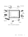
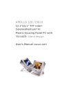
Figure 1-1:The panel PC in perspective.................................................... 3
Figure 1-2: How to read the PPC-150 manual .......................................... 5
Figure 2-1: Front view of the panel PC ................................................... 12
Figure 2-2: Left side view of the panel PC .............................................. 13
Figure 2-3: Rear view of the panel PC .................................................... 14
Figure 2-4: Tilted rear view of the panel PC ............................................ 15
Figure 2-5: Connecting the power cord ................................................... 16
Figure 2-6: Connecting the keyboard and mouse ................................... 21
Figure 3-1: Inserting and ejecting a floppy diskette ................................. 26
Figure 3-2: Inserting and ejecting a CD-ROM disc ................................. 27
Figure 3-3: Inserting and ejecting a PCMCIA card .................................. 28
Figure 3-4: Using the I/O interface
(upper level ports excluding COM ports) ......................................... 29
Figure 3-5: Using the I/O interface (lower level ports and COM ports) .... 30
Figure 3-6: PCI/ISA bus expansion ......................................................... 32
Figure 4-1: Disassembling the rear panel of the panel PC ...................... 40
Figure 4-2: Installing the primary 2.5" HDD ............................................. 41
Figure 4-3: Installing the CPU ................................................................. 43
Figure 4-4: Installing the SDRAM ........................................................... 44
Figure 4-5: Installing the FDD ................................................................. 44
Figure 4-6: Installing the CD-ROM drive ................................................. 46
Figure 5-1: Locating jumpers on the PPC-150 motherboard ................... 50
Figure 5-2: Locating connectors on the PPC-150 motherboard .............. 52
xiv
Figure 9-2: CMOS setup screen ........................................................... 105
Figure 9-3: BIOS features setup screen ............................................... 107
Figure 9-4: Chipset features setup screen ............................................ 110
Figure 9-5: Power Management setup screen ...................................... 111
Figure 9-6: PNP/PCI configuration setup screen .................................. 115
Figure 9-7: Load BIOS defaults screen ................................................. 117
Figure 9-8: Integrated peripherals screen ............................................. 118
Figure 9-9: IDE HDD auto detection screen .......................................... 122
Figure 9-10: Save and exit setup screen .............................................. 123
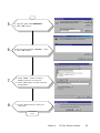
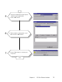
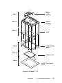
Figure C-1: Steps 1 - 4 ......................................................................... 153
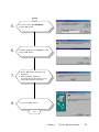
Figure C-2: Steps 5 - 6 ......................................................................... 155
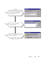
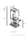
Figure C-3: Steps 7 - 12 ....................................................................... 157
Figure E-1: Cutout dimensions of the PPC-150 .................................... 178
Figure E-2: Panel mounting .................................................................. 179
Figure E-3: Dimensions of panel mounting holes .................................. 180
Figure E-4: Desktop stand mounting .................................................... 182
Figure E-5: Swingarm stand mounting .................................................. 183
xv
xvi
CHAPTER
1
General Information
This chapter gives background
information on the PPC-150 panel PC.
•
Introduction
•
How to Use This Manual
•
Specifications
1.1 Introduction
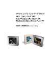
The PPC-150 panel PC is a multimedia Pentium® MMX processor-based
computer that is designed to serve as a human machine interface (HMI)
and as a desktop computer. It is a PC-based system with 15" color TFT
LCD display, on-board PCI Ethernet controller, multi-COM port interfaces and a 16-bit audio controller. With built-in CD-ROM drive, floppy
drive and PCMCIA expansion sockets, the PPC-150 is as compact and
user-friendly as a notebook computer. Unlike notebook computers, the
PPC-150 is more durable and versatile in all applications. The panel PC
can be placed on a desktop to replace the traditional desktop computer. In
addition, its "fit anywhere" design makes it very flexible and able to be
used in many different kinds of installations. It can be wall mounted,
panel mounted or stood upright on a desktop.
For system integrators, this simple, complete, compact and highly
integrated multimedia system lets you easily build a panel PC into your
applications. Common industrial applications include factory automation
systems, precision machinery, and production process control. It is also
suitable for many nonindustrial applications, including interactive kiosk
systems, entertainment management, and car park automation. Our panel
PC is a reliable, cost-effective solution to your application's processing
requirements.
2
PPC-150 User's Manual
Touchscreen
CRT Monitor
Network
Fax
modem
Speakers
Printer
Keyboard
Joystick
Mouse
Figure 1-1:The panel PC in perspective
Chapter 1
General Information
3
1.2 How to Use This Manual
This manual contains all the information you need to set up and use the panel
PC. In addition to this manual, you may also want to consult the manuals for
your operating system, software applications and peripherals.
Whether you are a new or an experienced user, you will benefit more from
this manual if you are familiar with its organization. This manual is divided
into ten chapters, plus five appendices.
Chapter 1 (this chapter) outlines the organization of this User's Manual,
provides a complete specification description of the PPC-150, and summarizes its main features.
Chapter 2 provides step-by-step instructions to help you set up and begin
using the panel PC as quickly as possible.
Chapter 3 provides important information about the daily use of the panel
PC, including using the CD-ROM drive, floppy drive and enjoying the panel
PC's audio capabilities.
Chapter 4 provides detailed step-by-step instructions to help you install the
internal key components, including the CPU, hard disk drive, memory
module, and so on.
Chapter 5 provides a detailed description of jumper settings and connectors
of the motherboard of the PPC-150.
Chapter 6 explains the PCI bus Ethernet setup.
Chapter 7 explains the PCI SVGA setup.
Chapter 8 explains the audio setup.
Chapter 9 explains the Award BIOS setup.
Chapter 10 explains how to configure and use the optional touchscreen.
Appendix A details the LCD specifications used in the PPC-150.
Appendix B explains how to program the watchdog timer.
Appendix C includes various exploded diagrams of the PPC-150. These
diagrams will help system integrators disassemble the panel PC.
Appendix D includes all pin assignments on the connectors.
4
PPC-150 User's Manual
Appendix E helps users install the panel PC, which is mountable in a variety
of ways.
If you are a commercial user and the panel PC unit you bought is a complete
set with CPU, hard disk drive, SDRAM, CD-ROM drive, floppy disk drive
and PCMCIA expansion slots included, you may only need to read Chapters
1 through 3 regarding hardware operation. For additional drivers and BIOS
setup information, you should read Chapters 6 through 9. If you want to
upgrade your system, you may follow the instructions in Chapters 4 and 5.
Chapter 10 is for users who want information about the optional touchscreen.
If you are a system integrator who wants to integrate the panel PC into your
system, you can refer to Appendices A through E for information such as pin
assignments and how to fully disassemble the panel PC.
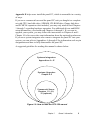
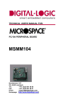
A suggested guideline for reading this manual is shown below:
Systems Integrators:
Appendices A - E
Systems Upgrades:
Chapter 4-5
Commercial Users:
Chapters 1-3, 6-9,
10 (optional)
Figure 1-2: How to read the PPC-150 manual
Chapter 1
General Information
5
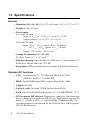
1.3 Specifications
General
• Dimensions (W x H x D): 420 x 323 x 106 mm (16.54" x 12.72" x 4.17")
• Weight: 6.5 kg (14.4 lbs)
• Power supply:
AC model: 80 watts
Input: 85 VAC / 3A ~ 264 VAC / 1.5A @ 47 ~ 63 Hz
Output voltage: +5 V @ 12 A, +12 V @ 1A
DC model: 60 watts
Input: 19 VDC ~ 30 VDC, typical 24 VDC, 5A max or
10.5 VDC ~ 16 VDC, typical 12 VDC, 7A max
Output: +5 V @ 10A, +12 V @ 1A
• Cooling fan dimensions (L x W x H):
40 x 40 x 10 mm (1.6" x 1.6" x 0.4")
• Disk drive housing: Space for one 2.5" HDD, one 12.7 mm compact CDROM drive, and one slim type 3.5" FDD
• Front panel: IP65 protection (not for the model with SAW touchscreen)
Standard PC functions
• CPU:
Intel Pentium® 75 ~ 233 MHz with MMX, P55C/P54C,
AMD K5, K6, K6-2, Cyrix M1, M2
• BIOS: Award 256KB Flash BIOS, supports Plug & Play, APM
• Chipset: SiS 5582
• 2nd level cache: On-board 512 KB Pipeline Burst SRAM
• RAM: One 168-pin DIMM socket accepts 16 ~ 128 MB SDRAM (3.3 V)
• PCI bus master IDE interface: Supports two connectors. Each connector
has one channel and supports two IDE devices. Each channel supports PIO
modes 0 ~ 4, DMA mode 0 ~ 2, and Ultra DMA 33 simultaneously. The
secondary connector is designated for the CD-ROM drive. BIOS supports
IDE CD-ROM boot-up.
6
PPC-150 User's Manual
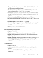
• Floppy disk drive: Supports up to two FDDs (720K/1.44MB). One builtin FDD included inside FDD housing
• Parallel port: One parallel port, supports SPP/EPP/ECP parallel mode.
BIOS configurable to LPT1, LPT2, LPT3 or disabled
• Serial ports: Four serial ports with three RS-232 ports (COM1, 3, and 4),
one RS-232/422/485 port (COM2). All ports are compatible with 16C550
UARTs.
• Universal serial bus (USB) port: Supports up to two USB ports
• PCI/ISA bus expansion slot: Accepts either one ISA card or one PCI bus
card
• Watchdog timer: 63-level, interval 1 ~ 63 seconds.
Automatically generates system reset or IRQ11 when the system stops due
to a program error or EMI. Jumperless selection and software enabled/
disabled
• Battery: 3.0 V @ 190 mA lithium battery
PCI SVGA/flat panel interface
• Chipset: C&T 65555
• Display memory: 2 MB on-board memory, supports up to 4 MB
• Display type: Simultaneously supports CRT and flat panel displays (EL,
LCD and gas plasma)
• Display resolution: Supports non-interlaced CRT and LCD displays up to
1024 x 768 @ 65536 colors. If display memory is expanded to 4 MB,
supports CRT and LCD displays up to 1280 x 1024 with true-color
resolution.
Audio function
• Chipset: ESS 1869
• Audio controller: 16-bit codec, Full-Duplex stereo single-chip audio
solution
• Stereo sound: 100% DOS GAME compatible (Sound Blaster or Sound
Blaster Pro)
Chapter 1
General Information
7
• Audio interface: Microphone in, line in, line out and game port.
PCI bus Ethernet interface
• Chipset: Realtek RTL 8139 PCI local bus Ethernet controller
• Ethernet interface: Full compliance with IEEE 802.3u 100Base-T and 10
Base-T specifications. Includes software drivers and boot ROM
• 100/10Base-T auto-sensing capability
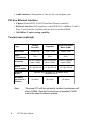
Touchscreen (optional)
Type
Analog
Resistive
Capacitive
Surface Acoustic
Wave (SAW)
Resolution
Continuous
1024 x 1024
4096 x 4096
75%
85%
91%
Controller
RS-232 interface
(uses COM4)
RS-232 interface
(uses COM4)
RS-232 interface
(uses COM4)
Power
Consumption
+5 V @ 200 mA
+5 V @ 100 mA
+5 V @ 150 mA
Light
Transmission
Software
Driver
Supports DOS, Windows 3.1, Windows 95/98,
Windows NT4.0
Durability
(touches in a
lifetime)
Note:
8
30 million
20 million
50 million
The panel PC with the optionally installed touchscreen will
share COM4. Once the touchscreen is installed, COM4
cannot be used for other purposes.
PPC-150 User's Manual
Optional modules
• CPU:
Intel Pentium® 75 ~ 233 MHz with MMX, P55C/P54C,
AMD K5, K6, K6-2 Cyrix M1, M2
• Memory: 16/32/64/128 MB SDRAM
• HDD: 2.5" HDD
• Touchscreen: Analog resistive,capacitive or Surface Acoustic Wave
• CD-ROM drive: Compact 24X CD-ROM or above
• PCMCIA interface: Complies with 1995 PCMCIA card standard.
Supports two PCMCIA card/CardBus slots. Two sockets support both a 16bit PCMCIA card and a 32-bit CardBus simultaneously. Hot insertion and
removal
Note 1:
The PCMCIA driver is an option which does not come with
the PCMCIA interface. For more information, contact your
local dealer or our sales representative.
Note 2:
Microsoft's new operating system, Windows 98,
supports the TI1250 PCMCIA function.
Environment
• Temperature: 0° ~ 45° C (32° ~ 122° F)
• Relative humidity: 10 ~ 95% @ 40 ° C (non-condensing)
• Shock: 10G peak acceleration (11 msec duration)
• Power MTBF: 100,000 hrs
• Certification:
AC Model: UL, VCCI, BSMI, CE, FCC class B
approval.
DC Model: CE, FCC class B approval and UL 2601, EN 60601compliance
Chapter 1
General Information
9
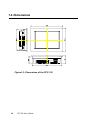
1.4 Dimensions
Figure1-3: Dimensions of the PPC-150
10
PPC-150 User's Manual
CHAPTER
2
System Setup
•
A Quick Tour of the Panel PC
•
Preparing for First-time Usage
•
Running the Setup Program
•
Installing the System Software
•
Installing the Drivers
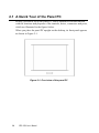
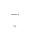
2.1 A Quick Tour of the Panel PC
Before you start to set up the panel PC, take a moment to become familiar
with the locations and purposes of the controls, drives, connectors and ports,
which are illustrated in the figures below.
When you place the panel PC upright on the desktop, its front panel appears
as shown in Figure 2-1.
Figure 2-1: Front view of the panel PC
12
PPC-150 User's Manual
When you look at the left side of the panel PC, you will see the floppy disk
drive, CD-ROM drive and PCMCIA expansion sockets, as shown in Fig. 2-2.
FDD eject button
FDD slot
FDD activity light
Compact CD-ROM drive
CD-ROM drive activity light
CD-ROM eject button
PCMCIA socket
PCMCIA eject button
Figure 2-2: Left side view of the panel PC
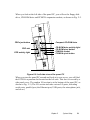
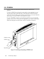
When you turn the panel PC around and look at its rear cover, you will find
the PCI/ISA expansion slot located on the left side. This slot is covered by a
side panel cover. The sunken I/O section is at the bottom of the panel PC, as
shown in Fig. 2-3. (The I/O section includes various I/O ports, including
serial ports, parallel port, the Ethernet port, USB ports, the microphone jack,
and so on.)
Chapter 2
System Setup
13
PCI/ISA expansion
slot cover
PS/2 mouse and
keyboard connector
USB ports
Ethernet jack
Brightness adjust knob
Contrast adjust knob
Line out jack
Line in jack
Microphone in jack
Figure 2-3: Rear view of the panel PC
14
PPC-150 User's Manual
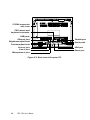
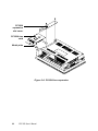
Parallel port
Serial ports
VGA port
Game port
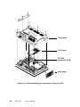
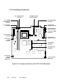
Figure 2-4 shows the I/O section and power switch of the panel PC.
Main
power switch
AC inlet
Figure 2-4: Tilted rear view of the panel PC
2.2 Preparing For First-time Use
Before you start to set up the panel PC system, you should have at least the
following items ready:
•
Power cord (in the accessory box)
•
Y-shaped connector (in the accessory box)
•
AT keyboard
•
PS/2 or serial mouse (for system software installation i.e. Microsoft
Windows, NT, etc.)
Chapter 2
System Setup
15
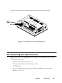
2.3 Installation Procedures
2.3.1 Connecting the AC power cord
The panel PC can be powered by an AC electrical outlet (85 ~ 264 volts,
47 ~ 63 Hz). Be sure to always handle the power cords by holding the plug
ends only.
Follow these procedures in order:
1. Connect the female end of the power cord to the AC inlet of the panel PC.
(See Fig. 2-5.)
2. Connect the 3-pin male plug of the power cord to an electrical outlet.
AC inlet
Electrical outlet
Power cord
Figure 2-5: Connecting the power cord
16
PPC-150 User's Manual
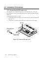
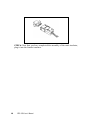
2.3.2 Installing the DC power insulator with hood
The panel PC can also be powered by DC electrical outlet (19 VDC ~ 30 VDC,
typical 24 VDC or 10.5 VDC ~ 16 VDC, typical 12 VDC, which depends on the
power type). Follow the procedure in order to install the DC power insulator
with hood then make sure to connect the insulator with the system.
3 contact pins
+
G
_
Negative power
cable
Positive power
cable
Frame ground
STEP 1. Connect the three contact pins individually to the negative and
positive power cables of the power adaptor, as well as to the frame ground
cable. Solder firmly.
Chapter 2
System Setup
17
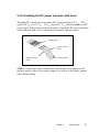
Female insulator
Male insulator
+
G
⁄@
STEP 2: Align the soldered pins and their cables with the corresponding polarization marks on the front part of the male insulator
(+ / G / -). Now plug the pins separately into the holes of the male
insulator. Pin 1 should go into the positive DC power input ( + ),
pin 2 connects to the frame ground ( G ), and pin 3 should be
plugged into the negative DC power input ( - ).
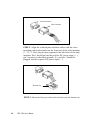
Bottom tray
STEP 3: Mount the front part of the male insulator onto the bottom tray.
18
PPC-150 User's Manual
Metal plate
STEP 4: Use the metal plate and the two screws to secure the cables to the bottom
tray. Please refer to the illustration above.
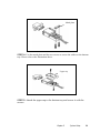
Upper cap
STEP 5: Attach the upper cap to the bottom tray and secure it with the
screws.
Chapter 2
System Setup
19
STEP 6: Now that you have completed the assembly of the male insulator,
plug it into the female insulator.
20
PPC-150 User's Manual
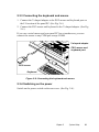
2.3.3 Connecting the keyboard and mouse
1. Connect the Y-shaped adapter to the PS/2 mouse and keyboard port on
the I/O section of the panel PC. (See Fig. 2-6.)
2. Connect the PS/2 mouse and keyboard to the Y-shaped adapter. (See Fig.
2-6.)
If you use a serial mouse and your panel PC has a touchscreen, you can
connect the mouse to any COM port except COM4.
Y-shaped adapter
PS/2 mouse and
keyboard port
PS/2 mouse
Keyboard
Figure 2-6: Connecting the keyboard and mouse
2.3.4 Switching on the power
Switch on the power switch on the rear cover. (See Fig. 2-4.)
Chapter 2
System Setup
21
2.4 Running the BIOS Setup Program
Your panel PC is likely to have been properly set up and configured by your
dealer prior to delivery. You may still find it necessary to use the panel PC's
BIOS (Basic Input-Output System) setup program to change system configuration information, such as the current date and time or your type of hard
drive. The setup program is stored in read-only memory (ROM). It can be
accessed either when you turn on or reset the panel PC, by pressing the "Del"
key on your keyboard immediately after powering on the computer.
The settings you specify with the setup program are recorded in a special
area of memory called CMOS RAM. This memory is backed up by a battery
so that it will not be erased when you turn off or reset the system. Whenever
you turn on the power, the system reads the settings stored in CMOS RAM
and compares them to the equipment check conducted during the power on
self-test (POST). If an error occurs, an error message will be displayed on
screen, and you will be prompted to run the setup program.
If you want to change the setup of BIOS, refer to Chapter 9 for more detailed
information.
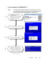
2.5 Installing System Software
Recent releases of operating systems from major vendors include setup
programs which load automatically and guide you through hard disk preparation and operating system installation. The guidelines below will help you
determine the steps necessary to install your operating system on the panel
PC hard drive.
Note:
Some distributors and system integrators may have already
pre-installed system software prior to shipment of your
panel PC.
If required, insert your operating system's installation or setup diskette into
the diskette drive until the release button pops out. (See Fig. 3-1.)
The BIOS of the panel PC supports system boot-up directly from the
CD-ROM drive. You may also insert your system installation CD-ROM into
the CD-ROM drive. (See Fig. 3-2.) Refer to Chapter 9 - BIOS Setup if you
wish to change the BIOS settings.
22
PPC-150 User's Manual
Power on your panel PC or reset the system by pressing the
"Ctrl"+"Alt"+"Del" keys simultaneously. The panel PC will automatically
load the operating system from the diskette or CD-ROM.
If you are presented with the opening screen of a setup or installation
program, follow the instructions on screen. The setup program will guide you
through preparation of your hard drive, and installation of the operating
system.
If you are presented with an operating system command prompt, such as
A:\>, then you must partition and format your hard drive, and manually copy
the operating system files to it. Refer to your operating system user's manual
for instructions on partitioning and formatting a hard drive.
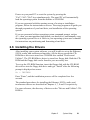
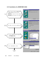
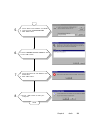
2.6 Installing the Drivers
After installing your system software, you will be able to set up the Ethernet,
SVGA, audio, and touchscreen functions. All the drivers except the CDROM drive driver are stored in a CD-ROM disc entitled "Drivers and
Utilities". The CD-ROM drive driver is stored in a floppy disk. Both the CDROM and the floppy disk can be found in your accessory box.
To set up the CD-ROM function, insert the floppy disk with the CD-ROM
drive driver into the floppy disk drive and type "install" after the following
prompt is displayed on screen:
A: > INSTALL
Press "Enter", and the installation process will be completed in a few
seconds.
The standard procedures for installing the Ethernet, SVGA, audio, and
touchscreen drivers are described in Chapters 6, 7, 8 and 10 respectively.
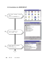
For your reference, the directory of drivers on the "Drivers and Utilities" CDROM is:
Chapter 2
System Setup
23
D:
Audio (drivers)
Document (manuals)
Elotouch (drivers)
LAN (Ethernet drivers)
Microtouch (drivers)
Utility
VGA (drivers)
The utility directory includes multimedia programs. Refer to the
README.TXT file inside the BIOS folder for more detailed information.
The various drivers and utilities in the CD-ROM disc have their own text
files which help users install the drivers and understand their functions.
These files are a very useful supplement to the information in this manual.
Note:
24
The drivers and utilities used for the PPC-150 panel PCs
are subject to change without notice. If in doubt, check
Advantech's web site or contact our application engineers
for the latest information regarding drivers and utlities.
PPC-150 User's Manual
CHAPTER
3
Using the Panel PC
•
Floppy Drive
•
CD-ROM Drive
•
PCMCIA Sockets
•
PS/2 Mouse and Keyboard
•
Audio Interface
•
PCI/ISA Bus Expansion
•
Parallel Port
•
Serial COM Ports
•
VGA Port
•
Game Port
•
USB Ports
•
Audio Interface
•
Ethernet
•
Adjusting the LCD Contrast and
Brightness
•
Touchscreen (Optional)
3.1 Introduction
This chapter describes basic features and procedures for using the panel PC.
Topics covered include the floppy drive, CD-ROM drive, I/O ports, touchscreen, and so on.
3.2 Floppy Drive
To insert a diskette, hold it with your left hand, between your thumb and
your other fingers, and push it toward the drive. (See Fig. 3-1.) Slide the disk
until it clicks into place. Note that new diskettes must be formatted by your
operating system before you can use them for data storage. See your operating system manual for details.
To eject a diskette, first ensure that the drive activity light is off, and then
press the eject button on the drive. When the diskette pops out of the drive,
remove it and store it properly.
Floppy Disk Drive
Floppy Disk
Figure 3-1: Inserting and ejecting a floppy diskette
26
PPC-150 User's Manual
3.3 CD-ROM Drive
To insert a CD-ROM disc, press the eject button of the CD-ROM drive. The
yellow activity light will flash and the front panel will come out a short
distance. Using your fingertips, hold the top and bottom of the front panel
and pull it outward to the very end. (See Fig 3-2.) Align the center hole of the
CD-ROM disc with the center circle of the CD-ROM holding plate. Press the
transparent ring around the center hole of the CD-ROM until you hear a
click. Push the front panel of the CD-ROM drive back to its original place.
To eject a CD-ROM disc, first ensure that the drive activity light is off. Then
press the eject button on the drive. When the disc pops out of the drive,
remove it and store it properly.
CD-ROM
holding plate
CD-ROM
Figure 3-2: Inserting and ejecting a CD-ROM disc
Chapter 3
Using the Panel PC
27
3.4 PCMCIA
PCMCIA cards are inserted and ejected in much the same way as
diskettes.
To insert a PCMCIA card, align the card with the socket and slide the card
into the socket until it locks into place. Note that some PCMCIA memory
cards must be prepared by your operating system before you can use them for
data storage. See your PCMCIA card manual for details.
To eject a PCMCIA card, first ensure that the panel PC is not accessing the
memory card or device. Then press the appropriate eject button on the socket.
When the card pops out of the socket, remove it and store it properly.
PCMCIA socket
PCMCIA card
Eject Button
Figure 3-3: Inserting and ejecting a PCMCIA card
28
PPC-150 User's Manual
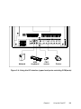
Network
USB
keyboard
PS/2
mouse
Printer
Figure 3-4: Using the I/O interface (upper level ports excluding COM ports)
Chapter 3
Using the Panel PC
29
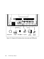
Headphones
CD-ROM
player Microphone
Joystick
CRT
monitor
Serial
mouse
Figure 3-5: Using the I/O interface (lower level ports and COM ports)
30
PPC-150 User's Manual
3.5 PS/2 Mouse and Keyboard
If you wish to use a full-size desktop keyboard and PS/2 mouse with your
panel PC, follow these instructions:
1. Be sure the panel PC is turned off.
2. Connect the Y-shaped adapter to the PS/2 mouse and keyboard port on
the rear bottom side of the rear cover. (See Fig. 3-4 and Fig. 2-6.)
3. Attach the keyboard to the 5-pin port of the Y-shaped adapter.
4. Attach the PS/2 mouse to the 6-pin female PS/2 port of the Y-shaped
adapter.
5. Turn on the panel PC.
3.6 PCI/ISA Bus Expansion
The panel PC supports PCI and ISA bus expansion cards. To integrate a new
PCI or ISA bus card into your system, follow these instructions:
1. Turn off the panel PC.
2. Unscrew the two screws on the top of the PCI/ISA bus expansion slot
cover, and remove this cover.
3. Remove the metal plate by unscrewing the single attaching screw.
4. Insert the PCI or ISA bus card into the PCI/ISA slot of the riser card. (See
Fig. 3-6 overleaf.)
5. Run the setup program within your operating system to configure your
system.
Chapter 3
Using the Panel PC
31
PCI/ISA
expansion
slot cover
PCI/ISA bus
card
Metal plate
Figure 3-6: PCI/ISA bus expansion
32
PPC-150 User's Manual
3.7 Parallel Port
The panel PC supports the latest EPP and ECP parallel port protocols for
improved performance and versatility with compatible printers or other
devices.
To connect the panel PC to a printer or other devices:
1. Be sure both the panel PC and the printer/devices are turned off.
2. Connect the 25-pin male connector of the printer cable to the 25-pin
female port on the panel PC labelled "parallel port".
3. If necessary, attach the other end of your printer cable to your printer, and
fasten any retaining screws. A typical parallel printer connection is
illustrated in Fig. 3-4.
4. Turn on the printer and any other peripheral devices you may have
connected to the panel PC, and then turn on the panel PC.
5. If necessary, run the panel PC's BIOS setup program to configure the
parallel port to respond as required by your printer and software operating
environment.
3.8 Serial COM Ports
There are four serial COM ports on the bottom of the rear cover. You can
easily attach a serial device to the panel PC, such as an external modem or
mouse. Follow these instructions:
1. Be sure the panel PC and any other peripherial devices you may have
connected to the panel PC are turned off.
2. Attach the interface cable of the serial device to the panel PC's serial port.
(See Fig. 3-5.) If necessary, attach the other end of the interface cable to
your serial device. Fasten any retaining screws.
3. Turn on any other peripheral devices you may have connected to the
panel PC, and then turn on the panel PC.
4. Refer to the manual(s) which accompanied your serial device(s) for
instructions on configuring your operating environment to recognize the
device(s).
5. Run the BIOS setup program and configure the jumper settings to change
the mode of the COM ports. (See Section 5.3.)
Chapter 3
Using the Panel PC
33
3.9 VGA Port
An external VGA-compatible device may be connected to the system
through the 15-pin external port located on the rear of the system unit. The
panel PC simultaneously supports an external CRT monitor in addition to its
own LCD display.
1. Be sure the panel PC is turned off.
2. Connect the external monitor to the system. (See Fig. 3-5.)
3. Turn on the panel PC and the external monitor.
3.10 Game Port
An external game device may be connected to the system through the 15-pin
external port located on the rear of the system unit.
1. Be sure the panel PC is turned off.
2. Connect the external joystick or game device to the system. (See Fig. 35.)
3. Turn on the panel PC and the external joystick or game device (if
applicable).
4. Install the driver before you use the joystick or game device.
3.11 USB Ports
An external USB device may be connected to the system through the 4-pin
USB ports located on the rear side of the system unit.
1. Connect the external device to the system. (See Fig. 3-4.)
2. The USB ports support hot plug-in connection. You should install the
device driver before you use the device.
34
PPC-150 User's Manual
3.12 Audio Interface
The audio interface includes three jacks: microphone in, line out and line in.
(See Fig. 3-5.) Their functions are:
Microphone in: Use an external microphone to record voice and sound.
Line out: Output audio to external devices such as speakers or earphones.
Line in: Input audio from an external CD player or radio.
1. Connect the audio device to the system. (See Fig. 3-5.)
2. Install the driver before you use the device.
3.13 Ethernet
External devices on your network may be connected to the system through
the external ethernet port located on the rear side of the system unit.
1. Be sure the panel PC is turned off.
2. Connect the external device(s) to the panel PC. (See Fig. 3-4.)
3. Turn on the panel PC and the external device(s).
4. Under DOS, run the RSET8139 program to check the hardware network
status before installing the Ethernet driver.
5. Run the Ethernet driver to connect up to the network.
3.14 Adjusting the LCD Contrast and Brightness
The contrast control knob does not function because the PPC-150 includes
the TFT LCD display. Only panel PCs with DSTN LCD displays have this
function.
The brightness control knob allows you to adjust the brightness of the LCD
display panel.
Chapter 3
Using the Panel PC
35
3.15Touchscreen (Optional)
The touchscreen is connected to COM4. Its function is similar to that of a
mouse. The only difference is that you put your fingertip on the screen to
move the cursor.
You will need to install the touchscreen driver before it will work. The
touchscreen drivers for various operating systems are stored on the CD-ROM
disc inside the accessory box. The touchscreen manual can also be found on
this disc. Read Chapter 10 of this manual carefully before you install the
driver.
36
PPC-150 User's Manual
CHAPTER
4
Hardware Installation
and Upgrading
•
Overview of Hardware Installation
and Upgrading
•
Disassembling the Panel PC
•
Installing the 2.5" Hard Disk Drive
(HDD)
•
Installing the Central Processing Unit
(CPU)
•
Installing the SDRAM Memory
Module
•
Installing the Floppy Disk Drive
(FDD)
•
Installing the CD-ROM Drive
4.1 Overview of Hardware Installation and
Upgrading
The panel PC consists of a PC-based computer that is housed in a plastic
rear panel and a shielding case. Your HDD, SDRAM, power supply, CPU,
and so on are all readily accessible by removing the rear panel and
shielding case. Any maintenance or hardware upgrades can be easily
completed after removing the rear panel and shielding case.
If you are a systems integrator and need to know how to completely
disassemble the panel PC, you can find more useful information in
Appendix C.
38
Warning!
Do not remove the rear cover until you have verified
that no power is flowing within the panel PC. Power
must be switched off and the power cord must be
unplugged. Every time you service the panel PC, you
should be aware of this.
PPC-150
User's Manual
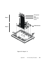
4.2 Disassembling the Panel PC
The following are standard procedures for disassembling the panel PC
before you upgrade your system. All procedures are illustrated in Fig. 4-1.
1. Unscrew the seven screws that secure the rear cover, then remove the
cover.
2. Unscrew the two screws of the PCI/ISA expansion PCB, and remove it.
3. Unscrew the four screws that secure the CPU cover.
4. Remove the floppy drive, HDD, and CD-ROM cables; then remove
the side panel.
5. Unscrew the ten screws of the shielding case, and remove it.
6. Detach the ventilation fan power cable.
Chapter 4
Hardware Installation and Upgrading
39
Rear panel
CPU cover
PCI/ISA
expansion PCB
Side panel
Figure 4-1: Disassembling the rear panel of the panel PC
40
PPC-150
User's Manual
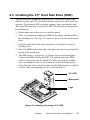
4.3 Installing the 2.5" Hard Disk Drive (HDD)
You can attach one enhanced Integrated Device Electronics (IDE) hard
disk drive to the panel PC's internal controller which uses a PCI local-bus
interface. The advanced IDE controller supports faster data transfer and
allows the IDE hard drive to exceed 528 MB. The following are instructions
for installation:
1. Detach and remove the rear cover and side panel.
2. There is a metal plate holding the HDD on the upper right-hand side of
the shielding case. (See Fig. 4-2.) Remove the two screws on the metal
plate.
3. Push the metal plate to the right and remove it from the two lugs of
shielding case.
4. Place the HDD on the metal plate, and tighten the four screws from the
bottom of the metal plate.
5. The HDD cable (1 x 44-pin to 1 x 44-pin) is next to the metal plate.
Connect the HDD cable to the HDD. The another end of the HDD
cable is connected to the PC board (J7). Make sure that the red/blue
wire corresponds to Pin 1 on the connector, which is labeled on the
board. Plug the other end of the cable into the IDE hard drive, with Pin
1 on the cable corresponding to Pin 1 on the hard drive.
2.5" HDD
Metal plate
Lugs
Figure 4-2: Installing the primary 2.5" HDD
Chapter 4
Hardware Installation and Upgrading
41
4.4 Installing the Central Processing Unit (CPU)
The panel PC's central processing unit (CPU) can be upgraded to improve
system performance. The panel PC provides one 321-pin ZIF (Zero
Insertion Force) socket (Socket 7) which is backward compatible with ZIF
Socket 5 processors. The CPU must come with an attached heatsink and
CPU fan to prevent overheating. The panel PC comes with one CPU fan
with a unique connector in the accessory box.
Warning!
The CPU may be damaged if operated without a
heatsink and a fan.
Warning!
Always disconnect the power cord from your panel PC
when you are working on it. Do not make connections
while the power is on as sensitive electronic components
can be damaged by the sudden rush of power. Only
experienced electronics personnel should open the panel PC.
1. Detach and remove the rear cover, shielding case and side panel.
2. Detach the flat cables of the HDD, FDD and CD-ROM drives.
3. Unscrew the ten screws of the shielding case and remove the case.
4. Locate the ZIF socket and open it by first pulling the lever sideways
away from the socket, then upwards at an angle of 90 degrees.
5. Insert the CPU with the correct orientation. The notched corner of the
CPU (with the white dot) should point towards the end of the lever.
The end of the lever is the blank area where one hole is missing from
the corner of the square array of pin holes. An arrowhead printed on
the motherboard points to the end of the lever. (See Fig. 4-3 overleaf.)
6. Slide the CPU in gently. It should insert easily. If not, pull the lever up
a little more and make sure the pins of the CPU correspond with the
holes of the socket. DO NOT USE EXCESSIVE FORCE!
7. Press the lever down. The plate will slide forward.
8. Place the heatsink on top of the CPU and tighten it with the heatsink
clip (shown in Fig. 4-3).
9. Attach the CPU fan to the CPU heatsink with the four screws.
42
PPC-150
User's Manual
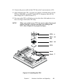
10. Connect the power cable of the CPU fan to the 2-pin connector (J12).
11. After changing the CPU, you must set jumpers, including those for the
PCI bus clock (JP8), system/PCI clock (JP11), frequency ratio (JP14),
and voltage (JP13). (See Section 5.2.)
12. To remove the CPU, pull the lever out to the side a little and raise it as
far as it will go. Lift out the CPU chip.
NOTE!
When you install a new CPU, be sure to adjust the board
jumper settings. Improper settings may damage the
CPU. (See Chapter 5 for jumper settings.)
CPU fan
Heat sink
clip
Heat sink
CPU
Lever
Socket 7
Figure 4-3: Installing the CPU
Chapter 4
Hardware Installation and Upgrading
43
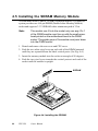
4.5 Installing the SDRAM Memory Module
You can install from 16 MB to 128 MB of SDRAM memory. The panel PC
system provides one 168-pin DIMM (Double Inline Memory Module)
socket and supports 3.3 V SDRAM with a minimum speed of 12 ns.
Note:
The module can fit into the socket only one way. Pin 1
of the DIMM module must line up with the small arrowhead printed on the motherboard next to the DIMM
socket. The golden pins of the module must point down
into the DIMM socket.
1. Detach and remove the rear cover and CPU cover.
2. Push the two white eject levers on each side of the DIMM outward
until they are separated from the black vertical posts. (See Fig. 4-4.)
3. Insert the memory module into the socket at an angle of 90 degrees.
4. Push the two eject levers towards the vertical posts at each end of the
socket until the module is upright.
SDRAM
Figure 4-4: Installing the SDRAM
44
PPC-150
User's Manual
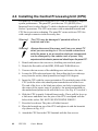
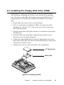
4.6 Installing the Floppy Disk Drive (FDD)
Installation of a floppy disk drive is similar to that for a hard disk drive.
The metal plate for holding the FDD is on the left side of the shielding
case. The 26-pin yellow FPC cable is for connecting the FDD. Only 3.5"
floppy disk drives (720 KB and 1.44 MB) can be attached to the metal
plate.
1. Detach and remove the rear cover and side panel.
2. There is a metal plate for holding the FDD on the right side of the
shielding case. (See Fig. 4-5.) Unscrew the two screws on the upper
side of the metal plate.
3. Push the metal plate to the right and remove it from the two lugs of the
shielding case.
4. Place the FDD on the metal plate. Tighten the four smaller screws
located on each side of the metal plate.
5. Connect the yellow FDD cable (26-pin to 26-pin) which is next to the
metal plate of the FDD. The other end of the FDD cable is connected to
connector J8 on the PC board.
6. Attach the two screws of the metal plate to the original hole.
3.5" floppy drive
Metal plate
Figure 4-5: Installing the FDD
Chapter 4
Hardware Installation and Upgrading
45
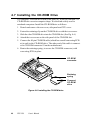
4.7 Installing the CD-ROM Drive
The compact CD-ROM drive used in the panel PC is not the common 5.25"
CD-ROM drive seen in computer shops. It is the kind widely used in
notebook computers. Install the CD-ROM drive as follows:
1. Detach and remove the rear cover, side panel and CPU cover.
2. Fasten the retaining clip on the CD-ROM drive with the two screws.
3. Slide the slim CD-ROM drive into the CD-ROM slot. (See Fig. 4-6.)
4. Attach the two screws on the side panel of the CD-ROM slot.
5. Connect the 40-pin CD-ROM cable (which has a small converting PCB
at its end) to the CD-ROM drive. The other end of the cable is connected to CD-ROM connector J9 on the motherboard.
6. Rotate the retaining spring, to secure the CD-ROM connector (with
converting PCB) in place.
CD-ROM
connector
Retaining
spring
Compact
CD-ROM
drive
Figure 4-6: Installing the CD-ROM drive
46
PPC-150
User's Manual
CHAPTER
5
Jumper Settings and
Connectors
This chapter tells how to set up the panel
PC hardware, including instructions on
setting jumpers and connecting peripherals,
switches and indicators. Be sure to read
all the safety precautions before you
begin the installation procedures.
•
Jumpers and Connectors
•
CPU Installation and Upgrading
•
COM Port Interface
•
VGA Interface
•
Watchdog Timer Configuration
5.1 Jumpers and Connectors
5.1.1 Setting jumpers
You can configure your panel PC to match the needs of your application by
setting jumpers. A jumper is the simplest kind of electrical switch. It consists
of two metal pins and a small metal clip (often protected by a plastic cover)
that slides over the pins to connect them. To “close” a jumper, you connect
the pins with the clip. To “open” a jumper you remove the clip. Sometimes a
jumper will have three pins, labeled 1, 2, and 3. In this case, you would
connect either pins 1 and 2 or pins 2 and 3.
1
Open
Closed
2
3
Closed 2 - 3
The jumper settings are schematically depicted in this manual as follows:
1
Open
Closed
Closed 2 - 3
A pair of needle-nose pliers may be helpful when working with jumpers.
If you have any doubts about the best hardware configuration for your
application, contact your local distributor or sales representative before you
make any changes.
48
PPC-150
User's Manual
5.1.2 Jumpers
The motherboard of the panel PC has a number of jumpers that allow you to
configure your system to suit your applications. The table below lists the
function of each of the board’s jumpers.
Table 5-1: Jumpers and their functions
Label
JP1
JP2
JP3
JP4
JP5
JP6
JP7
JP8
JP9
JP10
JP11
JP12
JP13
JP14
JP15
JP16
JP17
Function
COM3 RI pin setting (Reserved)
COM4 RI pin setting (Reserved)
COM2 RS-232/422/485 setting
COM2 RS-232/422/485 setting
COM2 RS-232/422/485 setting
Panel VCC setting
ENVEE pin setting
PCI bus clock setting
Panel type select
Cyrix linear mode enable
System/PCI clock setting
CMOS clear for external RTC
CPU VCORE voltage setting
CPU frequency ratio setting
Watchdog timer action
Reset
CMOS clear for 5582 internal RTC (Reserved)
Chapter 5
Jumper Settings and Connectors
49
5.1.3 Locating jumpers
JP14: CPU frequency ratio setting
JP11: System/PCI clock setting
JP13: CPU VCORE voltage setting
JP17: CMOS
clear for
internal RTC
JP9: Panel type select
Socket 7
JP6: Panel Vcc
setting
JP7: ENVEE
pin setting
JP8: PCI bus
clock setting
DIMM
JP15:
Watchdog
timer action
JP16: Reset
PCMCIA
JP10: Cyrix
linear mode
enable
JP5: COM2
RS-232/422/485
setting
JP12: CMOS
clear for
external RTC
JP2: COM4 RI
pin setting
(Reserved)
JP4: COM2
RS-232/422/485
setting
JP3: COM2
RS-232/422/485
setting
JP1: COM3 RI
pin setting
(Reserved)
Figure 5-1: Locating jumpers on the PPC-150 motherboard
50
PPC-150
User's Manual
5.1.4 Connectors
On-board connectors link the panel PC to external devices such as hard disk
drives or floppy drives. The table below lists the function of each of the
board’s connectors.
Table 5-2: Panel PC connectors
Label
J1
J2
J3
J4
J5
J6
J7
J8
J9
J10
J11
J12
J13
J15
J16
Function
IR connector (Reserved)
Flat panel display connector
Flat panel display connector
Internal COM4 connector
Touchscreen power connector
Sandisk SSD connector
EIDE hard disk driver connector
Floppy drive connector
CD-ROM connector
CPU fan power connector
PCI/ISA bus expansion connector
Fan power connector
AT power connector
Internal speaker connector (Reserved)
Inverter power connector
Chapter 5
Jumper Settings and Connectors
51
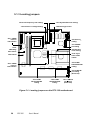
5.1.5 Locating connectors
J10: CPU fan power
connector
J7: EIDE hard disk
drive connector
J11: PCI/ISA
bus expansion
connector
J6: Sandisk SSD
connector
J12: Fan power
connector
J3: Flat panel
display connector
J5: Touchscreen
power connector
J4: Internal COM4
connector
Socket 7
J13: AT power
connector
J2: Flat panel
display connector
DIMM
J16: Inverter
power
connector
PCMCIA
J9: CD-ROM
connector
J8: Floppy drive
connector
J15: Internal
speaker
connector
(Reserved)
J1: IR connector
(Reserved)
Figure 5-2: Locating connectors on the PPC-150 motherboard
52
PPC-150
User's Manual
5.2 CPU Installation and Upgrading
You can upgrade to a higher power Pentium®, AMD or Cyrix processor at any
time. Simply remove the old CPU, install the new one, and set the jumpers for
the new CPU type and speed.
5.2.1 System clock setting (JP11, JP8)
JP11 and JP8 are used to set the CPU and PCI bus speeds respectively, to
optimize the system's performance. The system chipset will sense the JP8
setting to get the bus frequency, then adjust its internal timing. JP11 is used
to set the CPU and PCI clock. Refer to the CPU speed reference table for
instructions on adjusting the internal clocks according to the base CPU speed.
Chapter 5
Jumper Settings and Connectors
53
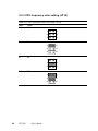
Table 5-3: System/PCI clock setting (JP11)
PCI clock
25 MHz
CPU clock
50 MHz
1
30 MHz
60 MHz
1
33 MHz
66 MHz
1
28 MHz
55 MHz
1
38 MHz
75 MHz
1
42 MHz
83 MHz
1
(Reserved)
54
PPC-150
User's Manual
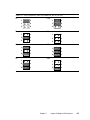
Table 5-4: PCI bus clock setting (JP8)
PCI clock
* CPUCLK/2
1
32MHz
1
* default setting
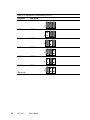
5.2.2 CPU core voltage setting (JP13)
JP13 must be set to match the CPU type. The following chart shows the
proper jumper settings for their respective VCC (CORE). (The VCC (I/O) for the
CPU is fixed at 3.3 V.)
Chapter 5
Jumper Settings and Connectors
55
Table 5-5: CPU voltage setting (JP13)
VCC (CORE)
1.30 V
VCC (CORE)
1.35 V
V CC (CORE)
1.45 V
10
9
10
9
10
9
10
9
8
7
8
7
8
7
8
7
6
5
6
5
6
5
6
5
4
3
4
3
4
3
4
3
2
1
2
1
2
1
2
1
1.50 V
1.55 V
1.60 V
1.65 V
10
9
10
9
10
9
10
9
8
7
8
7
8
7
8
7
6
5
6
5
6
5
6
5
4
3
4
3
4
3
4
3
2
1
2
1
2
1
2
1
1.70 V
1.75 V
1.80 V
1.85 V
10
9
10
9
10
9
10
9
8
7
8
7
8
7
8
7
6
5
6
5
6
5
6
5
4
3
4
3
4
3
4
3
2
1
2
1
2
1
2
1
1.90 V
56
VCC (CORE)
1.40 V
1.95 V
2.00 V
2.05 V
10
9
10
9
10
9
10
9
8
7
8
7
8
7
8
7
6
5
6
5
6
5
6
5
4
3
4
3
4
3
4
3
2
1
2
1
2
1
2
1
PPC-150
User's Manual
VCC (CORE)
NONE
V CC (CORE)
2.10 V
V CC (CORE)
2.20 V
VCC (CORE)
2.30 V
10
9
10
9
10
9
10
9
8
7
8
7
8
7
8
7
6
5
6
5
6
5
6
5
4
3
4
3
4
3
4
3
2
1
2
1
2
1
2
1
2.40 V
2.50 V
2.60 V
2.70 V
10
9
10
9
10
9
10
9
8
7
8
7
8
7
8
7
6
5
6
5
6
5
6
5
4
3
4
3
4
3
4
3
2
1
2
1
2
1
2
1
2.80 V
2.90 V
3.00 V
3.10 V
10
9
10
9
10
9
10
9
8
7
8
7
8
7
8
7
6
5
6
5
6
5
6
5
4
3
4
3
4
3
4
3
2
1
2
1
2
1
2
1
3.20 V
3.30 V
3.40 V
3.50 V
10
9
10
9
10
9
10
9
8
7
8
7
8
7
8
7
6
5
6
5
6
5
6
5
4
3
4
3
4
3
4
3
2
1
2
1
2
1
2
1
Chapter 5
Jumper Settings and Connectors
57
5.2.3 CPU frequency ratio setting (JP14)
Table 5-6: CPU frequency ratio (for Intel) (JP14)
P55C
3.5x
2x
3x
2.5x
58
PPC-150
P54C
1.5x
1
2
3
4
5
6
1
2
3
4
5
6
1
2
3
4
5
6
1
2
3
4
5
6
2x
3x
2.5x
User's Manual
Table 5-7: CPU frequency ratio (for AMD K6, K6-2) (JP14)
2x
2.5x
1
2
1
2
3
4
3
4
5
6
5
6
1
2
1
2
3
4
3
4
5
6
5
6
3x
3.5x
4x
4.5x
1
2
1
2
3
4
3
4
5
6
5
6
1
2
1
2
3
4
3
4
5
6
5
6
5x
5.5x
Chapter 5
Jumper Settings and Connectors
59
5.2.4 CMOS clear for external RTC (JP12)
Warning: To avoid damaging the computer, always turn off the power
supply before setting “Clear CMOS”. Set the jumper back to
“3.0 V Battery On” before turning on the power supply.
Table 5-8: Clear CMOS/External RTC (JP12)
* normal operation
Clear CMOS
1
2
1
2
* default setting
5.2.5 Cyrix linear mode enable (JP10)
The panel PC supports Cyrix M1 CPU with its linear access mode on L2
cache. This mode is set through JP10.
Table 5-9: Cyrix linear mode enable (JP10)
* open = disable (normal operation)
2
1
closed = Cyrix linear mode
2
1
* default setting
60
PPC-150
User's Manual
5.2.6 Reset system (JP16)
Table 5-10: Reset system (JP16)
* open = normal operation
2
1
closed = reset system
2
1
* default setting
Chapter 5
Jumper Settings and Connectors
61
5.3 COM-port Interface
The panel PC provides four serial ports (COM1, 3, 4: RS-232; COM2: RS232/422/485) in one COM port connector.
5.3.1 COM2 RS-232/422/485 setting (JP3, JP4, JP5)
COM2 can be configured to operate in RS-232, RS-422, or RS-485 mode.
This is done via JP3, JP4 and JP5.
Table 5-11: COM2 RS-232/422/485 setting (JP3, JP4)
* RS-232
2
RS-422/485
6
2
6
1
5
2
6
1
5
JP4
JP4
1
5
2
6
JP3
JP3
1
5
* default setting
Table 5-12: COM2 RS-232/422/485 setting (JP5)
* RS-232
RS-422
RS-485
4
5
6
4
5
6
4
5
6
1
2
3
1
2
3
1
2
3
* default setting
The IRQ and the address ranges for COM1, 2, 3, and 4 are fixed.
However, if you wish to disable the port or change these parameters later you
can do this in the system BIOS setup. The table overleaf shows the default
settings for the panel PC’s serial ports.
62
PPC-150
User's Manual
COM1 and COM2 are one set. You can exchange the address range and
interrupt IRQ of COM1 for the address range and interrupt IRQ of COM2.
After exchanging, COM1's address range is 2F8 ~ 2FF and its request IRQ is
IRQ3: and COM2's address range is 3F8 ~ 3FF and its interrupt IRQ is
IRQ4.
COM3 and COM4 are another set. Their selectable function is the same as
the COM1/COM2 set.
Table 5-13: PPC-150 serial port default settings
Port
COM1
COM2
COM3
COM4
Address Range
3F8 ~ 3FF
2F8 ~ 2FF
3E8 ~ 3EF
2E8 ~ 2EF
Interrupt
IRQ4
IRQ3
IRQ10
IRQ5
5.3.2 COM3/COM4/RI pin setting (JP2, JP1) (Reserved)
Table 5-14: COM4/RI pin setting (JP2)
+5 V output
+12 V output
* RI output
6
5
6
5
6
5
4
3
4
3
4
3
2
1
2
1
2
1
* default setting
Table 5-15: COM3/RI pin setting (JP1)
+5 V output
+12 V output
* RI output
6
5
6
5
6
5
4
3
4
3
4
3
2
1
2
1
2
1
* default setting
Chapter 5
Jumper Settings and Connectors
63
5.4 VGA Interface
The panel PC's’s PCI SVGA interface can drive conventional CRT
displays and is capable of driving a wide range of flat panel displays,
including electroluminescent (EL), gas plasma, passive LCD and active
LCD displays. The board has two connectors to support these displays
simultaneously; one for standard CRT VGA monitors and one for flat
panel displays.
CRT display port information can be found in Section 3.9 - VGA Port.
The pin assignments for the flat panel display connector, backlight
connector and other related connectors are described in the appendices.
5.4.1 LCD panel power setting (JP6)
The panel PC's’s PCI SVGA interface supports 5 V and 3.3 V LCD
displays. By changing the setting of JP6, you can select the panel video
signal level to be 5 V or 3.3 V.
Table 5-16: Panel V CC setting (JP6)
*5V
2
3.3 V
3
1
1
1
2
3
* default setting
Configuration of the VGA interface is done exclusively via the software
utility. You do not have to set any jumpers. Refer to Chapter 8 for
software setup details.
64
PPC-150
User's Manual
5.4.2 Panel type select (JP9)
Table 5-17: Panel type select (JP9)
Maximum
Resolution
1. 1024 x 768
Display
Type
DSTN color
Maximum
Resolution
2. 1280 x 1024
Display
Type
TFT color
7
8
7
8
5
6
5
6
3
4
3
4
1
2
1
2
3. 640 x 480
DSTN color
4. 800 x 600
DSTN color
7
8
7
8
5
6
5
6
3
4
3
4
1
2
1
2
5. 640 x 480
SHARP TFT color
6. 640 x 480
18-bit TFT color
7
8
7
8
5
6
5
6
3
4
3
4
1
2
1
2
7. 1024 x 768
TFT color
8. 800 x 600
TFT color
7
8
7
8
5
6
5
6
3
4
3
4
1
2
1
2
Chapter 5
Jumper Settings and Connectors
65
Maximum
Resolution
9. 800 x 600
Display
Type
TFT color
(44 K BIOS only)
8
7
8
5
6
5
6
3
4
3
4
1
2
1
2
DSTN color
(44 K BIOS only)
12. 800 x 600
DSTN color
7
8
7
8
5
6
5
6
3
4
3
4
1
2
1
2
13.1024 x 768 TFT color
(44 K BIOS only)
14. 1280 x 1024
DSTN color
(44 K BIOS only)
7
8
7
8
5
6
5
6
3
4
3
4
1
2
1
2
15. 1024 x 600
PPC-150
Display
Type
TFT color
7
11. 800 x 600
66
Maximum
Resolution
10. 800 x 600
TFT color
(48•K BIOS only)
16. 1024 x 600
TFT color
7
8
7
8
5
6
5
6
3
4
3
4
1
2
1
2
User's Manual
5.5 Watchdog Timer Configuration
An on-board watchdog timer reduces the chance of disruptions which
EMP (electromagnetic pulse) interference can cause. This is an invaluable
protective device for standalone or unmanned applications. Setup
involves one jumper and running the control software. (Refer to Appendix B.)
5.5.1 Watchdog activity selection (JP15)
When the watchdog timer activates (i.e. CPU processing has come to a
halt), it can reset the system or generate an interrupt on IRQ11. This can
be set via jumper JP15 as shown below:
Table 5-18: Watchdog activity selection (JP15)
* System reset
3
1
IRQ11
3
2
2
1
1
* default setting
Chapter 5
Jumper Settings and Connectors
67
68
PPC-150
User's Manual
CHAPTER
6
PCI Bus Ethernet
Interface
This chapter provides information on
Ethernet configuration.
•
Introduction
•
Installation of Ethernet Driver
-
•
Installation for MS-DOS &
WINDOWS 3.1
Installation for WINDOWS 95/98
Installation for WINDOWS NT
Further Information
6.1 Introduction
The PPC-150 is equipped with a high performance 32-bit Ethernet chipset
which is fully compliant with IEEE 802.3 100 Mbps CSMA/CD standards. It is supported by major network operating systems. It is also both
100Base-T and 10Base-T compatible. The medium type can be configured via the RSET8139.exe program included on the utility disk.
The Ethernet port provides a standard RJ-45 jack. The network boot
feature can be utilized by incorporating the boot ROM image files for the
appropriate network operating system. The boot ROM BIOS files are
combined with system BIOS, which can be enabled/disabled in the BIOS
setup.
6.2 Installation of Ethernet Driver
Before installing the Ethernet driver, note the procedures below. You must
know which operating system you are using in your PPC-150, and then
refer to the corresponding installation flow chart. Then just follow the
steps described in the flow chart. You will quickly and successfully
complete the installation, even if you are not familiar with instructions for
MS-DOS or WINDOWS.
70
Note 1:
The windows illustrations in this chapter are examples
only. You must follow the flow chart instructions and pay
attention to the instructions which then appear on your
screen.
Note 2:
The CD-ROM drive is designated as "D" throughout this
chapter.
PPC-150 User's Manual
6.2.1 Installation for MS-DOS & WINDOWS 3.1
If you want to set up your Ethernet connection under the MS-DOS
or Windows 3.1 environment, you should first check your server
operation system. For example, MS-NT, IBM-LAN server,Netware
and so on.
Then choose the correct driver to install in your panel PC.
The installation procedures for various servers can be found in the
directory path "LAN/TXT/*" of the drivers and utilities CD-ROM,
where * is your server model.
Chapter 6
PCI Bus Ethernet Interface
71
6.2.2 Installation for WINDOWS 95
1.
2.
a. S e le c t " Sta rt", "Se ttin gs ", "C o n tro l
Pa n el", " Sy ste m ".
b . C lic k " D e v ic e M an ag er", "O th er
D e vic es " ite m .
c . R e m o ve " PC I Ethe rn et C on tro lle r"
ite m .
a .S ele ct " Sta rt", "Se ttin gs ", "C o n tro l
P an el", a n d " N e tw o rk " ico n.
b . C lic k " A d d " b u tto n.
3.
a. S e le c t " A d ap ter", an d th e n c lic k "O K "
b utto n .
4.
a. P re s s " H a ve D is k..." b u tto n.
72
PPC-150 User's Manual
5.
a. T yp e th e p ath " D:\LAN \W IN95".
b . C lick " OK " b utto n.
6.
a .C ho os e the lig h te n ed " Realtek..." ite m .
b . C lick " OK" b utto n.
7.
a. P res s "Add..." bu tton to se le ct
s uitalb e se rvice s o r p roto cal.
b. P res s "OK " b utto n to fin ish n e tw ork
co n figu ratio n.
8.
a. P res s "Yes" bu tto n to start yo ur
c om pu ter.
e nd
Chapter 6
PCI Bus Ethernet Interface
73
6.2.3 Installation for WINDOWS 98
1.
a. Select " Start", "Settings", "Control
Panel", "System".
b. C lick "Device M anager", "O ther
Devices " item .
c. R em ove " PCI Ethernet Controller"
item .
2.
a. Select " Start", "Settings", "Control
Panel", and " Netw ork" icon.
b. C lick " Add" button.
3.
a. Select " Adapter", and then clic k "O K"
button.
4.
a. Pres s "Have Disk..." button.
74
PPC-150 User's Manual
5.
a. T yp e th e path " D:\LAN \W IN 98".
b . C lick "O K " b utto n.
6.
a .C hoose the lig h te n ed " Realtek..." item .
b . C lick " O K " b utto n.
7.
8.
a. P ress "O K " b utto n to re start your
c om puter.
b. A fte r re bootin g, win 98 can
re cogn ise R T L 8 13 9 and ask you to
in se rt "W in do ws 98 " C D -R O M .
a. P ress "Finish " b utto n.
e nd
Chapter 6
PCI Bus Ethernet Interface
75
6.2.4 Installation for WINDOWS NT
1.
2.
3.
4.
76
a. S ele c t " Start", "Settings ", "Control
P anel", a n d th en do u b le c lic k
"N etw ork" ic o n .
b . C h o os e the " A d apters " lab el.
c . C lic k the " A dd" b u tto n.
a.P res s " H ave D isk..." b u tto n.
a . In s ert th e " D rivers and U tilities "
C D -R O M .
b . F ill th e p ath " D :\LA N \W IN N T ".
c . P re s s the " O K " b u tto n.
a . C h o os e the " R TL8139... " ite m .
b . C lic k th e " O K " b u tto n.
PPC-150 User's Manual
5.
6.
7.
a . C hoo se s uitable R T L 8 13 9 D u ple x
m od e for yo u r a pp licatio n.
b . C lick " OK" b utto n.
a . F inish ne tw o rk co nfigu ration , and
the n click the " OK" b utto n.
a. P res s "Yes" b utto n to re start yo ur
c om pu ter.
e nd
Chapter 6
PCI Bus Ethernet Interface
77
6.3 Further Information
Realtek web: www.realtek.com.tw
Advantech web: www.advantech.com or www.advantech.com.tw
78
PPC-150 User's Manual
CHAPTER
7
PCI SVGA Setup
•
Introduction
•
Installation of SVGA Driver
-
•
Installation for WINDOWS 3.1
Installation for WINDOWS 95/98
Installation for WINDOWS NT
Installation for OS/2
Further Information
7.1 Introduction
The PPC-150 has an on-board PCI flat panel/VGA interface. The specifications and features are described as follows:
Chipset
The PPC-150 uses a C&T 65555 chipset for its PCI/SVGA controller. It
supports many popular LCD, EL, and gas plasma flat panel displays and
conventional analog CRT monitors. The 65555 VGA BIOS supports monochrome LCD, EL, color TFT and STN LCD flat panel displays. In addition, it
also supports interlaced and non-interlaced analog monitors (color and
monochrome VGA) in high-resolution modes while
maintaining complete IBM VGA compatibility. Digital monitors
(i.e. MDA, CGA, and EGA) are NOT supported. Multiple frequency
(multisync) monitors are handled as if they were analog monitors.
Display memory
With on-board 2 MB display memory, the VGA controller can drive CRT
displays or color panel displays with resolutions up to 1024 x 768 at 64 K
colors. The display memory can be expanded to 4 MB for true-color resolution of 1024 x 768.
Display types
CRT and panel displays can be used simultaneously. The PPC-150 can be set
in one of three configurations: on a CRT, on a flat panel display, or on both
simultaneously. The system is initially set to simultaneous display mode. The
CD-ROM disc includes three *.COM files in the subdirectory
Utility\vga\ which can be used to configure the display. In order to use
these configuration programs, type the file name and path at the DOS
prompt.
CT.COM: Enables CRT display only
FP.COM: Enables panel display only
SM.COM: Enables both displays simultaneously
80
PPC-150
User's Manual
7.2 Installation of SVGA driver
Complete the following steps to install the SVGA driver. Follow the procedures in the flow chart that apply to the operating system that you you are
using within your PPC-150.
Important: The following windows illustrations are examples only. You
must follow the flow chart instructions and pay attention to
the instructions which then appear on your screen.
Note 1:
The CD-ROM drive is designated as "D" throughout this
chapter.
Note 2:
<Enter> means pressing the "Enter" key on the
keyboard.
Chapter 7
PCI SVGA Setup
81
7.2.1 Installation for Windows 3.1
82
PPC-150
User's Manual
5.
a. Type the path of
the operating
system.
6.
a. When installation
is completed,
reboot the system.
b. You will see the
"ChipsCPL" icon in
the control panel.
7.
ChipsCPL
a. Double click
"ChipsCPL".
b. Adjust screen size,
color and refresh
rate to your
preferences.
END
Chapter 7
PCI SVGA Setup
83
7.2.2 Installation for Windows 95/98
84
PPC-150
User's Manual
5.
a. Select the
highlighted item.
b. Click the "OK"
button.
6.
a. C & T 6 5 5 5 5
appears in the
adapter label.
b. Click the "Apply"
button.
7.
a. Press "Yes" to
reboot.
8.
a. R e p e a t S t e p 1 o n
the previous page
of this manual.
The "CHIPS"
label appears in
"Display".
b. Adjust resolution
and color.
Chapter 7
PCI SVGA Setup
85
9.
a. Click the "CHIPS"
label.
b. Adjust the refresh
[7]
rate and display
type.
c. Press "OK" to
exit.
10.
a. Press "Yes" to
set the monitor
type.
11.
a. Select
"Standard",
"Super VGA 800
x 600", or "XGA".
b. Press the "OK"
button.
12.
a. Choose "Restart"
to reboot.
END
86
PPC-150
User's Manual
7.2.3 Installation for Windows NT
1.
a. Select "Start", "Settings",
"Control Panel".
b. Double click the "Display"
icon.
2.
a. Choose the "Settings" label.
b. Press the "Display Type"
button.
3.
a. Press the "Change..." button.
4.
a. Click the "Have Disk..."
button.
Chapter 7
PCI SVGA Setup
87
5.
a. Insert the disc into the
CD-ROM drive.
b. Type "D:\VGA\NT40\" in
the blank.
c. Press the "OK" button.
D:\VGA\NT40\
6.
a. Select the highlighted
item.
b. Press the "OK" button.
7.
a. Press "Yes" to proceed.
8.
a. Press "OK" to reboot.
88
PPC-150
User's Manual
9.
a. Repeat Step 1 in this
manual, to select the
"Settings" label.
b. Adjust resolution and color.
c. Click "Test" to see the
result.
d. Click "OK" to save the
setting.
END
Chapter 7
PCI SVGA Setup
89
7.2.4 Installation for OS/2
1.
a. Select "OS/2 System",
"Command Prompts",
"OS/2 Window".
b. Insert the disc into the
CD-ROM drive.
c. Type "D: ", <Enter>.
d. Type "setup D:C:", and
press <Enter>.
2.
a. Press "OK" to shut
down.
3.
a. Reboot again, by
selecting "OS/2
System", "System
Setup", "Display Driver
Install".
4.
a. Enable "Primary
Display".
b. Click the "OK" button.
90
PPC-150
User's Manual
5.
a. Press "OK" one more
time.
6.
a. Type "D:\" in the blank.
b. Click the "Install..."
button.
7.
a. Press "OK" to shut
down and restart.
8.
a. Select "OS/2 System",
"System Setup",
"System".
D:\
Chapter 7
PCI SVGA Setup
91
9.
a. Select the
"Screen" tab.
b. Change resolution
and refresh rate.
END
7.3 Further Information
For further information about the PCI/SVGA installation in your PPC-150,
including driver updates, troubleshooting guides and FAQ lists, visit the
following web resources:
C&T web site: www.chips.com
Advantech web sites: www.advantech.com
www.advantech.com.tw
92
PPC-150
User's Manual
CHAPTER
8
Audio
•
Introduction
•
Installation of Audio Driver
-
Installation for MS-DOS &
WINDOWS 3.1
Installation for WINDOWS 95/98
Installation for WINDOWS NT
Installation for OS/2
8.1 Introduction
The PPC-150 on-board audio interface provides high-quality stereo sound
and FM music synthesis (ESFM) by using the ES1869 audio controller from
ESS Technology, Inc. The audio interface can record, compress, and play
back voice, sound, and music with a built-in mixer control. The PPC-150 on
board audio interface also supports the Plug and Play (PnP) standard and
provides PnP configuration for audio, FM, and MPU-104 logical devices. It
is compatible with Sound Blaster, Sound Blaster Pro version 3.01, voice, and
music functions. The ESFM
synthesizer is register compatible with the OPL3 and has extended capabilities.
8.2 Installation of Audio Driver
Before installing the audio driver, please take note of the procedures detailed
below. You must know which operating system you are using in your
PPC-150, and then refer to the corresponding installation flow chart. Just
follow the steps in the flow chart. You can quickly and
successfully complete the installation, even though you are not familiar with
instructions for MS-DOS or WINDOWS.
Note:
The CD-ROM drive is designated as "D" throughout this
chapter.
8.2.1 Installation of MS-DOS
The ES1869 audio controller supports PC games and applications for Sound
Blaster and SoundBlaster Pro, with no need for a device driver in a DOS
environment. The default settings for the audio controller in DOS are:
94
Address: 220H
IRQ: 9
DMA: 1
MPU-401: Disabled
PPC-150
User's Manual
8.2.2 Changing settings in DOS
The audio controller settings can be changed in the DOS environment by
using the DOS SETUP utility located in the UTILITY subdirectory of the
CD-ROM. To change the settings, simply type DOSSET at the DOS prompt.
Follow the instructions on screen to choose the new settings for the ES1869
audio controller.
Chapter 8
Audio
95
8.2.3 Controlling volume in DOS
The ES1869 audio controller provides software control of the settings for
audio volumes. The VOLUME CONTROL utility located in the
UTILITY\Audio\ subdirectory of the CD-ROM is used to control the
volume settings in DOS. To control the volume settings, simply type "ESSVOL" at the DOS prompt with appropriate parameters. The script for
ESSVOL is:
ESSVOL [/?] [/v:xx] [/l:xx] [/w:xx] [/m:xx]
[/c:xx] [/s:xx] [/a:xx]
no option
Display all volume settings
/?
Display this message
/v
Change master volume
/l
Change line volume
/w
Change wave volume
/m
Change microphone volume
/c
Change CD volume
/s
Change synthesizer volume
/a
Change AuxB volume
/p
Change PC speaker volume
xx
Volume. Note: no xx means 0
The value range for volume is 0 ~ 15.
(The PC speaker volume range is 0 ~ 7.)
96
PPC-150
User's Manual
8.2.4 Installation for WINDOWS 3.1
Note:
The following windows illustrations are examples only. You
must follow the flow chart instructions and pay attention to
the instructions which then appear on your screen.
1.
a. Insert the disc into the
CD-ROM drive.
b. Select "File" in "Program
Manager" and click "Run".
c. Type "D:\Audio\win31\
setup.exe".
2.
a. Click "Continue" to install.
3.
a. Click "Driver Installation".
4.
a. Relative settings will be
added in "autoexec.bat".
b. Refer to the above section
to adjust the parameters.
D:\Audio\win31\setup.exe
END
Chapter 8
Audio
97
8.2.5 Installation for WINDOWS 95/98
1.
2.
3.
4.
98
a . R em ove ite m s re la ted to ESS1869 in
"O ther devices " folde r o f D e vice
M a n ag er.
b. C lic k "C lo se " b utton to e s ca pe " D evice
M an ager".
c. C lic k "A d d n e w ha rdw are " ico n, "N e xt".
a. S ele ct " N o ", and th e n c lic k " N ext " butto n.
a . C h oo se " So und , Video and gam e
co ntrollers " ite m .
b . C lick " N ext" butto n.
a . P re ss "H ave D isk... " butto n.
PPC-150
User's Manual
5.
a. Ins ert " D rive rs an d U tilitie s " C D -R O M .
b. T yp e th e p ath " D :\A udio\w in 95"
c . C lic k "O K " butto n.
6.
a. S ele ct " ES1869 C ontro l interface " ite m .
b. P res s "O k " butto n.
7.
a . In sert "W ind ow s 95 " C D -R O M to lo ad
rela te d file s.
b . C lick " O K " butto n.
8.
a . P re ss "Yes " bu tto n to start yo ur
c om pu ter.
END
Chapter 8
Audio
99
8.2.6 Installation for WINDOWS NT
1.
a. S ele ct " Start ", "S e ttin g s ", " C o n tro l
P an el".
b. D o ub le click " M u ltim ed ia " ico n.
2.
a. S e le ct the " D evices " ite m .
b . C lick the " A d d ..." butto n.
3.
a . C h oo se " U n listed or U p dated
D river" ite m .
b . C lick the " O K " butto n.
100
PPC-150
User's Manual
4.
5.
6.
a . Ins ert "D rive rs a n d U tilities " C D -R O M .
b . T yp e the pa th "D :\A udio\NT 40"
c . C lic k "O K " bu tto n .
a . S e lec t th e h igh lig hted ESS item .
b . P res s the "O k" bu tto n .
a . P res s the "R estart N ow " bu tto n to
re b oo t you r co m pu te r.
END
Chapter 8
Audio
101
102
PPC-150
User's Manual
CHAPTER
9
Award BIOS Setup
This chapter describes how to set BIOS
configuration data.
9.1 Award BIOS Setup
The PPC-150 comes with an Award BIOS chip that contains the ROM setup
for your system. This chip serves as an interface between the processor and
the rest of the mainboard's components. This chapter explains the information contained in the setup program and tells you how to modify the settings
according to your system configuration. Some setup items will not be
explained, because it is recommended that users do not change such items.
Note:
Values for the various setup items that appear on your own
screen (including default values) may not be the same as
the values shown on the screen figures in this chapter. This
is because the BIOS is revised and updated from time to
time. If in doubt, check
Advantech's web site for the latest BIOS versions and
related information.
9.2 CMOS Setup Utility
Figure 9-1: Setup program initial screen
104
PPC-150
User's Manual
A setup program, built into the system BIOS, is stored in the CMOS RAM
that allows the configuration settings to be changed. This program is executed when the user changes the system configuration; when the user changes
the system backup battery; or when the system detects a
configuration error and asks the user to run the setup program. At power-on
RAM testing, the message "Press DEL to enter Setup" appears. After
pressing the "DEL" key, the CMOS setup utility screen will appear as shown
in Fig. 9-1. Use the arrow keys to select and press "Enter" to run the selected
program.
9.3 Standard CMOS Setup
Figure 9-2: CMOS setup screen
The standard CMOS setup screen is shown above. System BIOS
automatically detects memory size, so no changes are necessary. It has a few
items requiring setting. Each item may have one or more optional settings.
System BIOS allows you to change the system date and time, IDE hard disk,
floppy disk drive types for drives A: and B:, boot-up video display mode,
and POST error handling selection. Use the arrow keys to highlight the item
and then use the "PgUp" or "PgDn" keys to select the value you want for
each item.
Chapter 9
Award BIOS Setup
105
9.3.1 Hard Disk Configurations
TYPE:
Select from 1 to 45 to fill the remaining fields with predefined values for disk
drives. Select "User" to fill the remaining fields. Select "Auto" to detect the
HDD type automatically.
SIZE:
Hard disk size. The unit is megabytes (MB).
CYLS:
The cylinder number of the hard disk.
HEAD:
The read/write head number of the hard disk.
PRECOMP:
The cylinder number at which the disk drive changes the write timing.
LANDZ:
The cylinder number where the disk drive heads (read/write) are seated when
the disk drive is parked.
SECTOR:
The sector number of each track defined on the hard disk.
MODE:
Select "Auto" to detect the mode type automatically. If your hard disk
supports the LBA mode, select "LBA" or "Large". However, if your hard
disk supporting cylinder is more than 1024 MB and does not support the
LBA function, you have to select "Large". If your hard disk supporting
cylinder is below 1024 MB, select "Normal".
106
PPC-150
User's Manual
9.4 BIOS Features Setup
Figure 9-3: BIOS features setup screen
Moving around the BIOS Features and Chipset Features setup programs
works the same way as moving around the Standard CMOS setup
program. (Refer to the next section for Chipset Features setup.) The BIOS
Features setup program is shown above. Users are not encouraged to run the
BIOS and Chipset Features setup programs. Your system should have been
fine-tuned before shipping. Improper setup may cause the system to fail, so
consult your dealer before making any changes.
V irus W
ar
ning
War
arning
When enabled, it assigns the BIOS to monitor the master boot sector and the
DOS sector of the first hard disk drive.
The options are: Disabled (Default), Enabled.
CPU Internal Cache
When enabled, it improves system performance. Disable this item when
testing or troubleshooting.
The options are: Enabled (Default), Disabled.
Chapter 9
Award BIOS Setup
107
External Cache
When enabled, supports an external cache SRAM.
The options are: Enabled (Default), Disabled.
Quick Power On Self TTest
est
When enabled, allows the BIOS to bypass the extensive memory test.
The options are: Disabled (Default), Enabled.
Boot Sequence
Allows the system BIOS to first try to boot the operating system from the
selected disk drive.
The options are: A, C (Default); C (only); C, CDROM, A; CDROM, C, A.
Swap Floppy Drive
When enabled, allows you to switch the order in which the operating system
accesses the floppy drives during boot-up.
The options are: Disabled (Default), Enabled.
Boot Up Floppy Seek
When enabled, assigns the BIOS to perform floppy disk drive tests by issuing
seek commands. Note that such tests are time-consuming.
The options are: Enabled (Default), Disabled.
Boot Up NumLock Status
When set to "On", allows the BIOS to automatically enable the NumLock
function when the system boots up.
The options are: On (Default), Off.
Memory Parity Check
The options are: Disabled (Default), Enabled.
T ypematic Rate Setting
The term typematic means that when a keyboard key is held down, the
character is repeatedly entered until the key is released. When this item is
enabled, you may change the typematic repeat rate.
The options are: Disabled (Default), Enabled.
108
PPC-150
User's Manual
Typematic Rate (Chars/Sec)
Sets the rate of a character repeat when the key is held down.
The options are: 6 (Default), 8, 10, 12, 15, 20, 24, 30.
Typematic Delay (msec)
Sets the delay time before a character is repeated.
The options are: 250 (Default), 500, 750, 1000 milliseconds.
Security Option
Allows you to set the security level of the system.
The options are: Setup (Default), System.
PCI/VGA Palette Snoop
When enabled, allows you to install an enhanced graphics adapter card. If
your graphics adapter card does not support the Palette Snoop function, set at
"Disabled" to avoid system malfunctions.
The options are: Disabled (Default), Enabled.
OS Select For DRAM > 64MB
If your operating system (OS) is OS2, select "OS2". Otherwise, stay with the
default setting Non-OS2.
V ideo BIOS Shadow
When enabled, allows the BIOS to copy the video ROM code of the add-on
video card to the system memory, giving faster access.
The options are: Enabled (Default), Disabled.
C8000-CBFFF Shadow thr
ough to DC000-DFFFF Shadow
through
When enabled, allows the BIOS to copy the BIOS ROM code of the add-on
card to the system memory for faster access. It may improve the performance
of the add-on card. Some add-on cards will not function properly if their
BIOS ROM codes are shadowed. To use this option correctly, you need to
know the memory address range used by the BIOS ROM of each add-on
card.
The options are: Disabled (Default), Enabled.
Chapter 9
Award BIOS Setup
109
9.5 Chipset Features Setup
Note:
It is strongly recommended that setup items in this section
NOT be changed, because advanced
knowledge is required to effect such changes.
Figure 9-4: Chipset features setup screen
System BIOS Cacheable
When enabled, allows the ROM area FOOOH-FFFFH to be cacheable when
the cache controller is activated. The recommended setting is "Disabled",
especially for high speed CPUs (200 MHz and above).
Video BIOS Cacheable
When enabled, allows the system to use the video BIOS codes from SRAMs,
instead of the slower DRAMs or ROMs.
The options are: Enabled (Default), Disabled.
110
PPC-150
User's Manual
Memory Hole at 15M-16M
When enabled, the memory hole at the 15 MB address will be relocated to
the 15 ~ 16 MB address range of the ISA cycle when the processor accesses
the 15 ~ 16 MB address area.
When disabled, the memory hole at the 15 MB address will be treated as a
DRAM cycle when the processor accesses the 15 ~ 16 MB address.
The options are: Disabled (Default), Enabled.
9.6 Power Management Setup
Figure 9-5: Power Management setup screen
Power Management
When enabled, allows you to use Power Management features.
The options are: Disabled (Default), Enabled.
Chapter 9
Award BIOS Setup
111
PM Contr
ol by APM
Control
The option "No" allows the BIOS to ignore the APM (Advanced Power
Management) specification. Selecting "Yes" will allow the BIOS to wait for
APM's prompt before it enters Doze mode, Standby mode, or Suspend mode.
If the APM is installed, it will prompt the BIOS to set the system into power
saving mode after all tasks are done.
The options are: Yes (Default), No.
Video Off Option
This feature provides the selections for the video display power saving mode.
The option "Susp, Stby → Off" allows the video display to go blank if the
system enters Suspend or Standby mode. The option "Suspend → Off"
allows the video display to go blank if the system enters Suspend mode. The
option "All Modes → Off" allows the video display to go blank if the system
enters Doze mode or Suspend mode. The option "Always On" allows the
video display to stay in Standby mode even when the system enters Doze or
Suspend mode.
The options are: Susp, Stby → Off (Default), Suspend → Off,
All Modes → Off, Always On.
Video Off Method
"DPMS Supported" allows the BIOS to blank off the screen display with
your VGA card which supports DPMS (Display Power Management Signaling function). "Blank Screen" allows the BIOS to blank the screen display by
turning off the red-green-blue signals.
The options are: DPMS Supported (Default), Blank Screen.
Doze Speed (div by)
The options are: 2 (Default), 1, 3, 4, 5, 6, 7, 8.
Stdby Speed (div by)
The options are: 3 (Default), 1, 2, 4, 5, 6, 7, 8.
MODEM Use IRQ
This feature allows you to select the IRQ# to meet your modem's IRQ#.
The options are: 3 (Default), 4, 5, 7, 9, 10, 11, NA.
112
PPC-150
User's Manual
Hot Key Power Of f
This function is designated as "Disabled".
HDD Of f After
Selecting "Disabled" will turn off the hard disk drive (HDD) motor. Selecting
"1 Min.. 15 Min" allows you to define the HDD idle time before the HDD
enters Power Saving Mode.
The options "1 Min.. 15 Min" and "When Suspend" will not work concurrently. When the HDD is in Power Saving Mode, any access to the HDD will
wake it up.
The options are: Disabled (Default), 1 Min.. 15 Min.
Doze Mode
The system will not enter Doze mode, because this option is designated as
"Disabled".
Standby Mode
The system will not enter Standby mode, because this option is designated as
"Disabled".
Suspend Mode
The system will not enter Suspend mode, because this option is designated as
"Disabled".
COM Ports Activity
Selecting "Enabled" will enable the power management timer when a no
activity event is detected in the COM ports. Selecting "Disabled" will disable
the PM timer even if a no activity event is detected.
The options are: Enabled (Default), Disabled.
LPT Ports Activity
Selecting "Enabled" will enable the power management timer when a no
activity event is detected in the LPT ports. Selecting "Disabled" will disable
the PM timer even if a no activity event is detected.
The options are: Enabled (Default), Disabled.
Chapter 9
Award BIOS Setup
113
HDD Ports Activity
Selecting "Enabled" will enable the power management timer when a no
activity event is detected in the hard disk drive. Selecting "Disabled" will
disable the PM timer even if a no activity event is detected.
The options are: Enabled (Default), Disabled.
VGA Activity
Selecting "Enabled" will enable the power management timer when a no
activity event is detected in the VGA. Selecting "Disabled" will disable the
PM timer even if a no activity event is detected.
The options are: Disabled (Default), Enabled.
IRQ# Activity
After the time period which you set in the Suspend Mode feature elapses, the
system advances from Doze Mode to Suspend Mode, in which the CPU
clock stops and the screen display is off. At this moment, if the IRQ activity
which is defined as enabled occurs, the system goes directly back to Full-on
Mode.
If the IRQ activity which is defined as "Disabled" occurs, the system enters
another low power state, Dream Mode. In Dream Mode, the system will
function the same as in Full-on Mode, except that the screen display remains
off until the corresponding IRQ handler finishes, whereupon the system
reverts to Suspend Mode.
For instance, if the system is connected to a LAN and receives an
interruption from its file server, the system will enter Dream Mode to execute
the corresponding calling routine.
The options are: Enabled, Disabled.
The default values of IRQ3, 4, 5, 6, 7, 9, 10, 11, 12, 13, 14, 15 are all:
Enabled.
The default value of IRQ8 is: Disabled.
114
PPC-150
User's Manual
Note:
Under certain operating systems such as Windoes NT 4.0
(Build 1381), the CD auto-insertion feature might have
some effect on power management. It is
recommended that the CD-ROM drive use the
secondary channel, and that the following Power Management Setup features be set:
HDD & FDD: Off
IRQ15 (Reserved): Secondary
9.7 PNP/PCI Configuration Setup
Figure 9-6: PNP/PCI configuration setup screen
Resour
ces Contr
olled By
Resources
Controlled
If set at "Auto", the BIOS automatically arranges all system resources for
you. If there are conflicts or you are not satisfied with the configuration,
simply set all the resources listed in the above figure by selecting
"Manual".
The options are: Manual (Default), Auto.
The manual options assigned to IRQ-/DMA- are: Legacy ISA, PCI/ISA PnP.
Chapter 9
Award BIOS Setup
115
Reset Configuration Data
When enabled, this feature allows the system to clear the last BIOS configuration data and then reset the data with the default BIOS
configuration data.
The options are: Disabled (Default), Enabled.
PCI IRQ Activated By
If your IDE card is triggered by edge, set it at "Edge".
The options are: Level (Default), Edge.
PCI IDE 2nd Channel
This item allows you to designate an IDE controller board inserted into one
of the PCI slots as your secondary IDE controller.
The options are: Enabled (Default), Disabled.
PCI IDE IRQ Map TTo
o
This item allows you to configure your system to the type of IDE disk
controller that you are using. By default, Setup assumes that your controller
is a PCI device rather than an ISA controller. The more
apparent difference is the type of slot being used.
Your system is equipped with a PCI controller. Selecting PCI-AUTO allows
you to specify which slot has the controller and which PCI interrupt (A, B, C
or D) is associated with the connected hard drives.
The options are: PCI-AUTO (Default), ISA.
Primary IDE INT#
Remember that this setting refers to the hard disk drive itself, rather than
individual partitions.
Secondary IDE INT#
Since each IDE controller supports two separate hard drives, you can select
the INT# for each. You will note that the primary has a lower interrupt than
the secondary.
Selecting PCI-AUTO allows the system to automatically determine how your
IDE disk system is configured.
116
PPC-150
User's Manual
9.8 Load BIOS Defaults
Figure 9-7: Load BIOS defaults screen
The BIOS defaults screen contains the most appropriate values of the system
parameters that allow minimum system performance.
9.9 Load Setup Defaults
Selecting this field loads the factory defaults for BIOS and Chipset Features.
The system will automatically detect these defaults.
Chapter 9
Award BIOS Setup
117
9.10 Integrated Peripherals
WDT Active When Power ON
63 sec
Figure 9-8: Integrated peripherals screen
Inter
nal PCI/IDE
Internal
When you select "Both", two PCI/IDE ports will be enabled. If you select
"Disabled", both PCI/IDE ports will be enabled. You can also select one of
two ports to be enabled by selecting "Primary" or "Secondary".
The options are: Both (Default), Disabled, Primary, Secondary.
IDE Primary/Secondary Master/Slave PIO
IDE hard disk drive controllers can support up to separate hard drives.
These drives have a master/slave relationship which is determined by the
cabling configuration used to attach them to the controller. Your system
supports two IDE controllers - a primary and a secondary - so you have the
ability to install up to four separate hard disks.
118
PPC-150
User's Manual
PIO means Programmed Input/Output. Rather than having the BIOS issue a
series of commands to effect a transfer to or from the disk drive, PIO allows
the BIOS to tell the controller what it wants and then let the controller and
the CPU perform the task by themselves.
Your system supports five modes, numbered from 0 through 4, which differ
primarily in timing. When "Auto" is selected, the BIOS will choose the best
available mode.
The options are: Auto, (Default), Disabled.
Primary/Secondary Master/Slave Ultra DMA
DMA means Direct Memory Access. Ultra DMA is faster than DMA. DMA
is a method of transferring data to or from memory at a fast rate, without
involving the CPU.
When you select "Auto", the BIOS will choose the best available mode.
The options are: Auto (Default), Disabled.
IDE Burst Mode
When enabled, data transfer on IDE buses will improve.
The options are: Disabled (Default), Enabled.
IDE HDD Block Mode
This allows your hard disk controller to use the fast block mode to transfer
data to and from your hard disk drive (HDD).
The options are: Enabled (Default), Disabled.
Onboard FDD Controller
When enabled, the floppy disk drive (FDD) controller is activated.
The options are: Enabled (Default), Disabled.
Chapter 9
Award BIOS Setup
119
WDT Active When Power ON
This is Advantech's patented watchdog function which can reboot the system
should the computer hang in the BIOS checkup.
The options are: 63 sec (Default), Disabled, 31 sec, 15 sec.
Onboar
d Serial Ports 1 & 2
Onboard
If the serial ports use the onboard I/O controller, you can modify your serial
port parameters.
The options for Port 1 are: 3F8/IRQ4 (Default), 2E8/IRQ3, Disabled,
2F8/IRQ3, 3E8/IRQ4.
The options for Port 2 are: 2F8/IRQ3 (Default), 3E8/IRQ4, 2E8/IRQ3,
Disabled, 3F8/IRQ4.
IR Addr
ess Select
Address
When enabled, the infrared receptor is activated.
The options are: Disabled (Default), Enabled.
Onboar
d Serial Ports 3 & 4
Onboard
If the serial ports use the onboard I/O controller, you can modify your serial
port parameters.
The options for Port 3 are: 3E8/IRQ10 (Default), 2E8/IRQ5, Disabled.
The options for Port 4 are: 2E8/IRQ5 (Default), Disabled, 3E8/IRQ10.
Onboar
d Parallel Port
Onboard
If the parallel port uses the onboard I/O controller, you can modify your
parallel port paramaters. When you select "Disabled", the next two setup
items will disappear.
The options are: 378/IRQ7 (Default), 3BC/IRQ7, 278/IRQ5, Disabled.
Parallel Port Mode
You can choose different data transfer modes for your system.
The options are: ECP & EPP (Default), SPP, EPP, ECP.
120
PPC-150
User's Manual
ECP Mode Use DMA
You can choose different DMA modes for data transfer.
The options are: 3 (Default), 1.
PS/2 mouse function
When enabled, the PS/2 mouse is activated.
The options are: Disabled (Default), Enabled.
USB Controller
When enabled, the USB devices are activated.
The options are: Disabled (Default), Enabled.
Ether
net Boot ROM
Ethernet
When enabled, your system will be able to boot up through the Ethernet.
The options are: Disabled (Default), Enabled.
Panel TType
ype
The panel type is designated by the manufacturer, according to your LCD
panel type.
9.11 Password Setting
To enable the password setting, select the item from the Standard CMOS
Setup. You will be prompted to create your own password. Type your
password up to eight characters and press "Enter". You will be asked to
confirm the password. Type the password again and press "Enter". You may
also press "Esc" to abort the selection and not enter a password. To disable
the password, press "Enter" when you are prompted to enter the password. A
message will appear, confirming the password is disabled.
Under the BIOS Features setup, if "System" is selected under the Security
Option field and the Supervisor Password is enabled, you will be
prompted for the supervisor password every time you try to enter the CMOS
Setup utility. If "System" is selected and User Password is enabled, you will
be requested to enter the user password every time you reboot the system. If
"Setup" is selected under the Security Option field and User Password is
enabled, you will be prompted only when you reboot the system.
Chapter 9
Award BIOS Setup
121
9.12 IDE HDD Auto Detection
Figure 9-9: IDE HDD auto detection screen
The IDE Hard Disk Drive Auto Detection feature automatically
configures your new hard disk. Use it for quick configuration of new hard
disk drives. This feature allows you to set the parameters of up to four IDE
HDDs. The option with "(Y)" is recommended by the system BIOS. You
may also key in your own parameters instead of setting them
according to the system BIOS. After keying in all settings, press "Esc" to
return to the main menu. For confirmation, enter the Standard CMOS Setup
feature.
122
PPC-150
User's Manual
9.13 Save and Exit Setup
Figure 9-10: Save and exit setup screen
After you have made changes in the BIOS setup, press "Esc" to return to the
main menu. Move the cursor to "Save and Exit Setup", or press "F10" and
then press "Y", to change the CMOS Setup. If you did not change anything,
press "Esc" again or move the cursor to "Exit Without Saving" and press "Y"
to retain the setup settings. The following message will appear at the center
of the screen to allow you to save data to CMOS and exit the setup utility:
SAVE to CMOS and EXIT (Y/N)?
9.14 Exit Without Saving
If you select this feature, the following message will appear at the center of
the screen to allow you to exit the setup utility without saving CMOS
modifications:
Quit Without Saving (Y/N) ?
Chapter 9
Award BIOS Setup
123
124
PPC-150
User's Manual
CHAPTER
10
Touchscreen
•
Introduction
•
Installation of Driver for Resistive or SAW
Touchscreen
-
•
Installation for MS-DOS &
WINDOWS 3.1
- Installation for Windows 95/98
- Installation for WINDOWS NT
- Installation for OS/2
Installation of Driver for Capacitive
Touchscreen
-
Installation for Windows 95/98/NT
10.1 Introduction
10.1.1 General information
The PPC-150's optional touchscreen incorporates advanced second-generation 5-wire resistive, impact-resistant capacitive, or surface acoustic wave
(SAW) technology. They allow 75%, 85%, and 91% light transmission
respectively. The resistive and capacitive models have an antiglare surface,
but the SAW model does not. All models provide greatly enhanced visual
resolution. They also have new improved scratch-resistant features.
The touchscreen is manufactured from UL-recognized components. When
properly installed, the touchscreen's ball impact resistance meets the UL
1950 standard. Its fire resistance meets the UL-746C, 19mm (0.75") flame
test standard. Systems incorporating the touchscreen, controllers, and cables
have been approved to FCC Class A and Class B standards.
For more detailed information, please visit the following web sites:
Resistive and SAW models: www.elotouch.com
Capacitive model: www.microtouch.com
10.1.2 Specifications
Please refer to the chapter 1. All of the specifications of touchscreens can
be found in chapter1.3.
10.1.3 Environmental specifications
Temperature:
-10° ~ 50° C (operating)
-40° ~ 71° C (storage)
Relative humidity:
90 RH at 35° C (operating)
90 RH at 35° C for 240 hours, noncondensing (storage)
Chemical Resistance: The active area of the touchscreen is resistant to the
following chemicals when exposed for a period of one hour at a temperature of 21° C (71° F):
- Acetone
126
PPC-150
User's Manual
- Methylene chloride
- Methyl ethyl ketone
- Isopropyl alcohol
- Hexane
- Ammonia-based glass cleaners
- Turpentine
- Mineral spirits
- Foods and beverages
10.2 Installation of Driver for Resistive or SAW
Touchscreen
The touchscreen driver for Windows 95 contains a native, 32-bit driver
designed for Windows 95/98 and a 32-bit control panel program for the
PPC-150 system.
To facilitate the installation of the touchscreen driver, you should read the
instructions in this chapter carefully before you attempt installation.
Note 1:
The following windows illustrations are examples only. You
must follow the flow chart instructions and pay attention to
the instructions which then appear on your screen.
Note 2:
The CD-ROM drive is designated as "D" throughout this
chapter.
Note 3:
<Enter> means pressing the "Enter" key on the keyboard.
Chapter 10
Touchscreen
127
10.2.1 Installation for MS-DOS and Windows 3.1
1.
a. Execute "install.exe" in
the DOS environment.
b. Press <Enter> to
continue.
2.
a. Type the installing
path of the ELO
directory.
3.
a. Select "Dos.." or
"Windows..".
Windows 3.1
a. Follow the on-screen
instructions.
4.
DOS
Windows 3.1
a. Choose the "Serial"
item.
5.
128
PPC-150
User's Manual
6.
a. Select the "COM4"
item.
7.
a. Press <Enter> to
install.
8.
a. Set serial port IRQ to
5.
Windows 3.1
a. Type the Windows 3.1
path.
9.
DOS
Windows 3.1
10.
a. Add "nomouse.com" to
"autoexec.bat" if there
is no mouse driver
installed.
b. If yes, the window
disappears.
Chapter 10
Touchscreen
129
11.
a. Press <Enter> to
continue.
12.
a. Choose "Overwrite...".
Windows 3.1
13.
a. Press <Enter> to
continue.
DOS
14.
Windows 3.1
a. Choose "Overwrite...".
Windows 3.1
15.
130
a. Type "go" to run
calibration.
b. Touch fix points to
calibrate.
PPC-150
User's Manual
16.
a. Add -M6 behind
monmouse in
"autoexec.bat" to add
"drag".
END
Chapter 10
Touchscreen
131
10.2.2 Installation for WINDOWS 95/98
If you want to use the touchscreen driver CD-ROM accompanying your
panel PC, refer to the following flow chart instructions.
1.
a . In s ert the "D riv ers and U tilities v 2 .0"
C D -R O M .
b . C lic k "S ta rt" b u tto n, a nd the n "R u n".
c . T yp e the p ath "D :\e loto uc h\w in95 \
s etu p".
2.
a. S elec t " S m a rt s e rial c ontrolle r o n
C O M 4" item .
b. P res s "O k" bu tton .
3.
a . C lic k "Y es " b utton to res tart yo u r
c o m p ute r.
4.
a. T ou ch ta rge ts to calib rate th e
tou c hs cre e n co ntrolle r.
132
PPC-150
User's Manual
10.2.3 Installation for WINDOWS NT
1.
a. Insert the "Drivers and
Utilities" CD-ROM.
b. Select "Start", "Run".
c. Type the path.
eg. "D:\Elotouch\
monmouse\winnt\
setup.exe"
2.
a. Press the "Next"
button.
3.
a. Set the directory path.
4.
a. Choose "Typical".
D:\Elotouch\monmouse\winnt\setup.exe
Chapter 10
Touchscreen
133
5.
a. Choose the COM port which
is not used by other devices.
b. Click "OK".
6.
a. Click "OK" but do not reboot.
7.
a. Click on the "My Computer"
icon, and navigate to:
"C":\winnt\system32\regedt32.
8.
a. From the left window, select:
"Hkey_Local_Machine"
"System", "CurrentControlSet",
"Services", "Monmouse",
"Parameters".
134
PPC-150
User's Manual
9.
a. Modify the items in right
window:
ComPort 4
ControllerAddress 2e8
ControllerLevel 5
ControllerVector 5
b. Click "OK" to save the
settings.
10.
a. Exit and reboot.
b. Select "Start", "Settings",
"Control Panel".
c. Double click "Elo
touchscreen".
11.
a. Click "Calibrate".
12.
a. Test the calibration.
END
Chapter 10
Touchscreen
135
10.2.4 Installation for OS/2 (MonitorMouse)
BEFORE YOU BEGIN
First be sure OS/2 is installed and operating properly with your mouse. As
you will be modifying the CONFIG.SYS file, it is best to have the OS/2
installation disks or a bootable DOS disk readily available. This way, any
problems in CONFIG.SYS which cause the system not to boot can be
corrected by rebooting from the disk(s).
Five steps are required when installing MonitorMouse for OS/2:
Step 1 - Configure your Controller
Step 2 - Copy the Software
Step 3 - Modify CONFIG.SYS
Step 4 - Install the Touchscreen Control Panel
Step 5 - Calibrate the Touchscreen
STEP 1 - CONFIGURE YOUR CONTROLLER
Verify your controller configuration. Elo typically ships touchscreen
controllers preconfigured for use with Elo software, including
MonitorMouse for OS/2. Configuration requires setting switches and/or
installing jumpers that determine controller operating parameters. You will
need these parameters when you install the MonitorMouse for OS/2 driver
software. For controller installation instructions, refer to the IntelliTouch
Product Manual or the AccuTouch Product Manual.
136
PPC-150
User's Manual
STEP 2 - COPY THE SOFTWARE
The following files are on the MonitorMouse for OS/2 disk:
!READ.ME!
Text file containing any additions or changes made after
this manual was printed.
MONMOU01.SYS Touchscreen driver for serial touchscreen controllers on
PC bus systems.
MONMOU02.SYS Touchscreen driver for serial touchscreen controllers on
Micro Channel systems.
MONMOU03.SYS Touchscreen driver for PC bus and Micro Channel
touchscreen controllers.
ELOCAL2.EXE
Touchscreen control panel software program used to
calibrate the touchscreen and to select options.
ELOCAL2.DLL
Used by ELOCAL2.EXE.
ELOCAL2.HLP
Help file for ELOCAL.EXE.
ELO.BMP
Elo desktop wallpaper.
@6253.ADF
Description file for the E271-2202 Micro Channel
touchscreen controller.
COMDUMP.EXE
DOS program for testing serial touchscreen
controllers.
BUSSTAT.EXE
DOS program for testing PC bus touchscreen controllers.
SAWDUMP.EXE
DOS program for testing IntelliTouch touchscreen
controllers.
Create a subdirectory on your hard disk and copy the files into it. For
example:
CD \
MD ELO
COPY A:*.* ELO
International versions of the touchscreen control panel software program are
included in subdirectories on the MonitorMouse for OS/2 disk. Replace
ELOCAL2.DLL and ELOCAL2.HLP on your hard disk with the versions
from the appropriate subdirectory.
Chapter 10
Touchscreen
137
STEP 3 - MODIFY CONFIG.SYS
MonitorMouse for OS/2 is installed by commands in CONFIG.SYS. Use
your system editor to make these changes. In general, the changes are as
follows:
1. Comment-out the existing DEVICE command(s) for your mouse.
2. Add a DEVICE command for the appropriate MonitorMouse for the OS/2
touchscreen driver immediately after the commented-out DEVICE
commands(s).
3. Add a new DEVICE command for MOUSE.SYS.
The order of the DEVICE commands is important. Other changes may be
required depending on your hardware configuration and version of OS/2.
Serial Touchscreen Controller on PC Bus System
Change your CONFIG.SYS file as follows:
Rem C:/OS2\MOUSE.SYS {Flags}
Device=c:\elo\monmou01.sys <controller>, <COM
port>,<baud rate>
Device=c:\os2\mouse.sys stype=elomou$ {Flags - keep
same as above}
Where:
<controller> is:
2300 for the IntelliTouch E281-2300 serial controller.
4002 for the IntelliTouch E281{A}-4002 serial controller.
2210 for the AccuTouch E271-2210 serial controller.
140 for the AccuTouch E271-140 serial controller.
<COM port> is:
the number of the COM port where the serial output of the touchscreen
controller is connected.
<baud rate>
matches the switch or jumper settings on the controller.
138
PPC-150
User's Manual
Example MonitorMouse for OS/2 DEVICE command:
Device=c:\elo\monmou01.sys 2210,1,9600
No Mouse
If you do not wish to have a mouse connected, change the “stype=elomou$”
flag to “type=elomou$” on the DEVICE=MOUSE.SYS command.
Disabling the COM Drivers
If your system COM ports are being used by the touchscreen and mouse,
REM out the DEVICE=COM.SYS and DEVICE=VCOM.SYS commands (if
present) in CONFIG.SYS. This prevents the COM drivers from displaying
amessage saying the COM port is unavailable.
If only the touchscreen is using a COM port, move the DEVICE=COM.SYS
and DEVICE=VCOM.SYS commands before the
DEVICE=MONMOU02.SYS command in CONFIG.SYS. Then add the flag
(<COM Port>,0,0) to COM.SYS, where <COM Port> is the same as on the
DEVICE=MONMOU01.SYS command. For example,
Device=c:\os2\com.sys (1,0,0)
Chapter 10
Touchscreen
139
STEP 4 - INSTALL THE TOUCHSCREEN CONTROL PANEL
The touchscreen control panel software program, ELOCAL2.EXE, is a
presentation manager application for calibrating the touchscreen and setting
various options.
Add the \ELO\ELOCAL2.EXE program to the System Setup folder and label
the icon “Touchscreen”. This is accomplished as follows:
1. Open the OS/2 System folder, then System Setup.
2. Open the Templates folder.
3. Drag the Program template with the right mouse button into the System
Setup folder. A Settings notebook will be displayed.
4. Enter “C:\ELO\ELOCAL2.EXE” as the path and file name. Enter
“C:\ELO” as the working directory.
5. Select the "General" tab. Change the Title to “Touchscreen”.
6. Close the notebook.
See your OS/2 documentation for detailed instructions on installing new
applications.
STEP 5 - CALIBRATE THE TOUCHSCREEN
Double-click the Touchscreen icon with the mouse (as the touchscreen may
not be calibrated yet), or use the keyboard if the mouse is not connected.
You may also run ELOCAL2.EXE from an OS/2 Window prompt.
Select "Calibrate" and follow the on-screen instructions. After calibrating, the
touchscreen will work like the mouse. The DEVICE=MONMOUxx command in CONFIG.SYS is updated with the new calibration points
(-c flag). The calibration points are then set automatically each time the
system is started. Recalibration should only be necessary after moving or
resizing the video image, or after changing either the touchscreen, controller,
or monitor.
Close the touchscreen control panel.
140
PPC-150
User's Manual
10.3 Installation of Driver for Capacitive Touch
screen
To facilitate installation of the touchscreen driver, you should read the
instructions in this chapter carefully before you attempt installation.
Note 1:
The following windows illustrations are examples only. You
must follow the flow chart instructions and pay attention to
the instructions which then appear on your screen.
Note 2:
The CD-ROM drive is designated as "D" throughout this
chapter.
Note 3:
<Enter> means pressing the "Enter" key on the
keyboard.
Chapter 10
Touchscreen
141
10.3.1 Installation for Windows95/98/NT
a.
b.
Select "Start", "Run".
Type in: D:\
PPC120&150\
Microtouch\Tware54\
Setup.exe
a.
2.
Follow the
installation
instructions, and
click on "Next".
3.
a. If you accept the
terms of the
License Agreement,
click on "Yes".
1.
4.
a.
b.
142
PPC-150
Select the Serial
[Default] controller.
Click on "Next".
User's Manual
5.
a.
b.
a.
Select the "Yes, ..."
item to reboot the
system and finish the
touchscreen driver
installation.
a.
Click on "Calibrate"
to calibrate the
touchscreen.
Touch the "target
point" for a moment,
until the next "Touch
enable" message
appears. Then touch
the next "target
point".
6.
b.
7.
8.
Select the "Express
Install..." item.
.
Click on "Next".
a.
Click on "Done" to
save the
calibration data.
End
Chapter 10
Touchscreen
143
144
PPC-150
User's Manual
APPENDIX
A
LCD Specifications and
Selection Settings
Appendix A
LCD Specifications and Selection Settings
144
Table A-1: PPC-150 series LCD specifications
Display type (LCD)
Max. resolution
Colors
15" TFT LCD
1024 x 768
256 K colors or above
Dot size
0.297 x 0.297
Viewing angle
110
Luminance
200 cd/m2
Temperature
0 ~ 50 C
*VR controls
Brightness
Simultaneous mode
Yes
LCD MTBF
50,000 hours
Backlight MTBF
25,000 hours
* The VR control knobs are located on the I/O section on the rear cover of
the panel PC.
Note:
146
The color LCD display installed in the panel PC is
high-quality and reliable. However, it may contain a few
defective pixels which may not always illuminate. With
current technology, it is impossible to completely eliminate
defective pixels. Advantech is actively working to improve
this technology.
PPC-150 User's Manual
APPENDIX
B
Programming the
Watchdog Timer
The PPC-150 is equipped with a watchdog timer that resets the CPU or generates
an interrupt if processing comes to a
standstill for any reason. This feature
ensures system reliability in industrial
standalone or unmanned environments.
Programming the Watchdog Timer
To program the watchdog timer, you must write a program which writes I/O
port address 443 (hex). The output data is a time interval value. The value
range is from 01 (hex) to 3F (hex), and the related time interval is from 1 sec.
to 63 sec.
Data
Time Interval
01
1 sec.
02
2 sec.
03
3 sec.
04
4 sec.
•
•
•
•
•
•
3F
63 sec.
After data entry, your program must refresh the watchdog timer by rewriting
the I/O port 443 (hex) while simultaneously setting it. When you want to
disable the watchdog timer, your program should read I/O port 443 (hex).
The following example shows how you might program the watchdog timer in
148
PPC-150 User's Manual
BASIC:
10
20
30
40
50
60
70
80
REM Watchdog timer example program
OUT &H443, data REM Start and restart the watchdog
GOSUB 1000 REM Your application task #1,
OUT &H443, data REM Reset the timer
GOSUB 2000 REM Your application task #2,
OUT &H443, data REM Reset the timer
X=INP (&H443) REM, Disable the watchdog timer
END
1000
•
•
•
1070
2000
•
•
•
2090
REM Subroutine #1, your application task
•
•
•
RETURN
REM Subroutine #2, your application task
•
•
•
RETURN
Appendix B
Programming the Watchdog Timer
149
150
PPC-150 User's Manual
APPENDIX
Full Disassembly
Procedures
C
If you want to completely disassemble the panel PC, follow the step-by-step
procedures below. Users should be aware that Advantech Co., Ltd. takes no
responsibility whatsoever for any problems or damage caused by the user
disassembly of the panel PC. Make sure the power cord of the panel PC is
unplugged before you start disassembly.
The following procedures do not include the detailed disassembly procedures
for the CPU, HDD, CD-ROM drive, FDD, and SRAM; all of which can be
found in Chapter 4.
1. Unscrew the seven screws on the rear cover, and remove it. The PCI/ISA
expansion slot cover can be detached by removing the two additional
screws.
2. Remove the side panel by pushing it outward.
3. Unscrew the four screws that attach the CPU cover.
4. Detach the flat cable of the HDD, FDD and CD-ROM drive. Remove the
two screws on the PCI/ISA bus expansion card. Remove the ten screws
on the side rim of the shielding case. Carefully move the shielding case to
the right to bypass the eject buttons of the PCMCIA slot, before removing
the case from the machine.
152
PPC-150 User’s Manual
Step 1
&
Step 2
Step 4
Step 3
Figure C-1: Steps 1 - 4
Appendix C
Full Disassembly Procedures
153
5. Unscrew the fourteen screws of the I/O bracket with a hexagonal screwdriver. The EMI protection cover lies below the I/O bracket. You can
now remove both the bracket and the cover from the I/O ports.
6. Detach the flat cables of the LCD inverter, touchscreen and LCD from the
motherboard. You can remove the motherboard from the plastic housing.
154
PPC-150 User’s Manual
I/O bracket
EMI
protection
cover
Step 5
Motherboard
Step 6
Figure C-2: Steps 5 - 6
Appendix C
Full Disassembly Procedures
155
7. Unscrew the four screws on the power supply board. The power supply
board can be detached from the plastic housing after unplugging the
cables from the motherboard.
8. Remove the front panel by hand.
9. Unscrew the ten screws on the LCD holding plate to seperate the plastic
housing and LCD holding plate.The LCD inverter can also be detached
by unscrewing the three screws at the bottom (Toshiba LCD only).
10. Detach the plastic housing.
11. Detach the LCD by unscrewing the four screws located on the each
corners.
12.The touchscreen is stuck on the LCD holding plate by a strongly doubleside adhensive tape. We do not recommend you to remove it unless the
touchscreen is defective and you would like to replace it.
Note:
156
Because of the modular design of the LCD and touchscreen, you do not disassemble the whole system step by
step if you would like to replace the defective LCD or
touchscreen. You just start disassembling the module from
the step 8. Then you can easily remove the LCD and
touchscreen by step 9 to step 12.
PPC-150 User’s Manual
Power
supply
Step 7
Plastic
housing
Step 10
Step 11
LCD
LCD holding
plate
Step 9
Step 12
Touchscreen
Step 8
Front panel
Figure C-3: Steps 7 - 12
Appendix C
Full Disassembly Procedures
157
158
PPC-150 User’s Manual
APPENDIX
Pin Assignments
D
•
IR Connector (J1) (Reserved)
•
Flat Panel Display Connector (J2)
•
Flat Panel Display Connector (J3)
•
Internal COM4 Connector (J4)
•
Touchscreen Power Connector (J5)
•
Sandisk SSD Connector (J6)
•
EIDE Hard Disk Drive Connector (J7)
•
Floppy Drive Connector (J8)
•
CD-ROM Connector (J9)
•
CPU Fan Power Connector (J10)
•
PCI/ISA Bus Expansion Connector
(J11)
•
Fan Power Connector (J12)
•
AT Power Connector (J13)
•
Internal Speaker Connector (J15)
(Reserved)
•
Inverter Power Connector (J16)
•
COM2
IR Connector (J1) (*Reserved)
1
Table D-1: IR Connector (J1)
Pin
1
2
3
4
5
160
Signal
VCC
Mode_Select
IR_IN
GND
IR_out
PPC-150 User’s Manual
2
3
4
5
Flat Panel Display Connector (J2)
Table D-2: Flat Panel Display Connector (J2)
Pin
1
3
5
7
9
11
13
15
17
19
21
23
25
27
29
31
33
35
37
39
41
43
Signal
+12 V
GND
VDD SAFE
ENAVEE
P0
P2
P4
P6
P8
P10
P12
P14
P16
P18
P20
P22
GND
SHFCLK
M/DE
GND
NC
NC
Pin
2
4
6
8
10
12
14
16
18
20
22
24
26
28
30
32
34
36
38
40
42
44
Signal
+12 V
GND
V DD SAFE
GND
P1
P3
P5
P7
P9
P11
P13
P15
P17
P19
P21
P23
GND
FLM
LP
ENABKL
NC
NC
Appendix D
44
42
40
38
36
34
32
30
28
26
24
22
20
18
16
14
12
10
8
6
4
2
Pin Assignments
43
41
39
37
35
33
31
29
27
25
23
21
19
17
15
13
11
9
7
5
3
1
161
Flat Panel Display Connector (J3)
15
13
11
9
7
5
3
1
16
14
12
10
8
6
4
2
Table D-3: Flat Panel Display (J3)
Pin
1
3
5
7
9
11
13
15
Signal
V DD SAFE
P24
P26
P28
P30
P32
P34
GND
Pin
2
4
6
8
10
12
14
16
Signal
+5 V
P25
P27
P29
P31
P33
P35
GND
Internal COM4 Connector (J4)
1
2
3
4
5
6
7
8
9
10
Table D-4: Internal COM4 Connector (J4)
Pin
1
3
5
7
9
162
Signal
DCD
RX
TX
DTR
GND
PPC-150 User’s Manual
Pin
2
4
6
8
10
Signal
DSR
RTS
CTS
RI
GND
Touchscreen Power Connector (J5)
1
2
Table D-5: Touchscreen Power Connector (J5)
Pin
1
2
Signal
+5 V
GND
Appendix D
Pin Assignments
163
Sandisk SSD Connector (J6)
43 41 39...
...5 3 1
44 42 40...
...6 4 2
Table D-6: Sandisk SSD Connector (J6)
Pin
1
3
5
7
9
11
13
15
17
19
21
23
25
27
29
31
33
35
37
39
41
43
Signal
IDE RESET #
DATA 7
DATA 6
DATA 5
DATA 4
DATA 3
DATA 2
DATA 1
DATA 0
SIGNAL GND
HDD 0
IO WRITE
IO READ
HD READY
HDACK 0 #
IRQ14
ADDR 1
ADDR 0
HDD SELECT 0 #
IDE ACTIVE 0 #
GND
GND
# Low active
164
PPC-150 User’s Manual
Pin
2
4
6
8
10
12
14
16
18
20
22
24
26
28
30
32
34
36
38
40
42
44
Signal
GND
DATA 8
DATA 9
DATA 10
DATA 11
DATA 12
DATA 13
DATA 14
DATA 15
N/C
GND
GND
GND
N/C
GND
N/C
N/C
ADDR 2
HDD SELECT 1 #
GND
VCC
N/C
EIDE Hard Disk Drive Connector (J7)
43 41 39...
...5 3 1
44 42 40...
...6 4 2
Table D-7: EIDE Hard Disk Drive Connector (J7)
Pin
1
3
5
7
9
11
13
15
17
19
21
23
25
27
29
31
33
35
37
39
41
43
Signal
IDE RESET #
DATA 7
DATA 6
DATA 5
DATA 4
DATA 3
DATA 2
DATA 1
DATA 0
SIGNAL GND
HDD 0
IO WRITE
IO READ
HD READY
HDACK 0 #
IRQ14
ADDR 1
ADDR 0
HDD SELECT 0 #
IDE ACTIVE 0 #
GND
GND
Pin
2
4
6
8
10
12
14
16
18
20
22
24
26
28
30
32
34
36
38
40
42
44
Signal
GND
DATA 8
DATA 9
DATA 10
DATA 11
DATA 12
DATA 13
DATA 14
DATA 15
N/C
GND
GND
GND
N/C
GND
N/C
N/C
ADDR 2
HDD SELECT 1 #
GND
VCC
N/C
# Low active
Appendix D
Pin Assignments
165
Floppy Drive Connector (J8)
1
Pin
1
2
3
4
5
6
7
8
9
10
11
12
13
166
Signal
VCC (+5 V)
INDEX
VCC (+5 V)
DRIVE SELECT
VCC (+5 V)
DISK CHANGE
NC
NC
NC
MOTOR ON
NC
DIRECTION
DENSITY SELECT
PPC-150 User’s Manual
Pin
14
15
16
17
18
19
20
21
22
23
24
25
26
Signal
STEP
GND
WRITE DATA
GND
WRITE DATA
GND
TRACK 0
GND
WRITE PROTECT
GND
READ DATA
GND
SIDE 1 SELECT
1
Table D-8: Floppy Drive Connector (J8)
1
2
3
4
5
6
7
8
9
10
11
12
13
14
15
16
17
18
19
20
21
22
23
24
25
126
CD-ROM Connector (J9)
Table D-9: CD-ROM Connector (J9)
Pin
1
3
5
7
9
11
13
15
17
19
21
23
25
27
29
31
33
35
37
39
Signal
Audio_L
GND
IDE RESET #
DATA7
DATA6
DATA5
DATA4
DATA3
DATA2
DATA1
DATA0
GND
IO WRITE
HD READY
IRQ 15
ADDR1
ADDR0
HDD SELECT 0 #
V CC (+5 V)
GND
Pin
2
4
6
8
10
12
14
16
18
20
22
24
26
28
30
32
34
36
38
40
Signal
Audio_R
GND
DATA8
DATA9
DATA10
DATA11
DATA12
DATA13
DATA14
DATA15
HDD 0
IO READ
GND
HD ACK 0 #
NC
NC
ADDR2
HDD SELECT 1 #
VCC (+5 V)
GND
1
2
3
4
5
6
7
8
9
10
11
12
13
14
15
16
17
18
19
20
21
22
23
24
25
26
27
28
29
30
31
32
33
34
35
36
37
38
39
40
# Low active
CPU Fan Power Connector (J10)
1
2
Table D-10: CPU Fan Power Connector (J10)
Pin
1
2
Signal
+12 V
GND
Appendix D
Pin Assignments
167
PCI/ISA Bus Expansion Connector (J11)
B1
F1
F2
F3
F4
F5
E1
B2
E2
B3
E3
B4
E4
B5
E5
B6
F8
F9
E7
B8
B9
B10
E10
B11
F11
B12
E11
F12
B13
F13
B14
F14
F15
E8
E9
F10
E12
E13
E14
B15
B16
E15
B18
F18
B19
F19
B20
F20
B21
F21
B22
F22
B23
F23
B24
F24
B25
E17
E18
E19
E20
E21
E22
E23
E24
side view
E26
B27
F27
B28
F28
B29
F29
B30
F30
B31
E28
E30
E31
D1
H3
D2
H4
D3
G3
G4
G5
D4
H9
H10
H11
D6
G7
G8
D7
G9
D8
G10
D9
G11
D10
G12
H12
D11
H13
D12
H14
G13
G14
D13
H17
H18
H19
168
PPC-150 User’s Manual
A9
A10
A11
A12
A13
A14
A15
A17
A18
A19
A20
A21
A22
A23
A24
A26
A27
A28
A29
A30
A31
D15
G16
G17
D16
C2
C3
C5
C6
C7
C8
C9
C10
C11
C12
C14
C15
G18
C16
G19
C17
D17
D18
C1
C13
D14
H16
A8
C4
D5
H8
A7
G2
H2
H7
A5
G1
H1
H5
E27
E29
F31
A4
A25
B26
F26
A3
A16
B17
F17
A2
A6
B7
F7
A1
C18
Table D-11: PCI/ISA Slot Pin Assignments (Pins A and B)
Pin
A1
A2
A3
A4
A5
A6
A7
A8
A9
A10
A11
A12
A13
A14
A15
A16
A17
A18
A19
A20
A21
A22
A23
A24
A25
A26
A27
A28
A29
A30
A31
Signal
IOCHK
SD7
SD6
SD5
SD4
SD3
SD2
SD1
SD0
IORDY
AEN
SA19
SA18
SA17
SA16
SA15
SA14
SA13
SA12
SA11
SA10
SA9
SA8
SA7
SA6
SA5
SA4
SA3
SA2
SA1
SA0
Pin
B1
B2
B3
B4
B5
B6
B7
B8
B9
B10
B11
B12
B13
B14
B15
B16
B17
B18
B19
B20
B21
B22
B23
B24
B25
B26
B27
B28
B29
B30
B31
Signal
GND
RST
VCC
IRQ9
-5 V
DRQ2
-12 V
OWS
+12 V
GND
SMW
SMR
IOW
IOR
DACK3
DRQ3
DACK1
DRQ1
REF
SCLK
IRQ7
IRQ6
IRQ5
IRQ4
IRQ3
DACK2
TC
ALE
VCC
OSC
GND
Appendix D
Pin Assignments
169
Table D-12: PCI/ISA Slot Pin Assignments (Pins C and D)
Pin
C1
C2
C3
C4
C5
C6
C7
C8
C9
C10
C11
C12
C13
C14
C15
C16
C17
C18
170
Signal
SBHE
LA23
LA22
LA21
LA20
LA19
LA18
LA17
MEMR
MEMW
SD8
SD9
SD10
SD11
SD12
SD13
SD14
SD15
PPC-150 User’s Manual
Pin
D1
D2
D3
D4
D5
D6
D7
D8
D9
D10
D11
D12
D13
D14
D15
D16
D17
D18
Signal
MEM16
IO16
IRQ10
IRQ11
IRQ12
IRQ15
IRQ14
DACKO
DRQ0
DACK5
DRQ5
DACK6
DRQ6
DACK7
DRQ7
V CC
MASTER
GND
Table D-13: PCI/ISA Slot Pin Assignments (Pins E and F)
Pin
E1
E2
E3
E4
E5
E6
E7
E8
E9
E10
E11
E12
E13
E14
E15
E16
E17
E18
E19
E20
E21
E22
E23
E24
E25
E26
E27
E28
E29
E30
E31
Signal
GND
GND
INT 1
INT 2
VCC
--VCC
RST
GNT2
REQ2
GND
PCLK1
GND
AD30
NC
--NC
AD28
AD26
AD24
AD22
AD20
AD18
NC
----AD16
FRAME
CBE2
TRDY
STOP
Pin
F1
F2
F3
F4
F5
F6
F7
F8
F9
F10
F11
F12
F13
F14
F15
F16
F17
F18
F19
F20
F21
F22
F23
F24
F25
F26
F27
F28
F29
F30
F31
Signal
GND
GND
INT3
INT4
VCC
--VCC
PCLK2
(V)
GNT3
GND
REQ3
AD31
AD29
NC
--NC
AD27
AD25
CBE3
AD23
AD21
AD19
NC
--NC
AD17
IRDY
DEVSEL
LOCK
PERR
Appendix D
Pin Assignments
171
Table D-14: PCI/ISA Slot Pin Assignments (Pins G and H)
Pin
G1
G2
G3
G4
G5
G6
G7
G8
G9
G10
G11
G12
G13
G14
G15
G16
G17
G18
G19
172
Signal
----CBE1
PAR
GND
--GND
AD13
AD11
AD9
CBEO
AD6
AD4
AD2
--V CC
V CC
GND
GND
PPC-150 User’s Manual
Pin
H1
H2
H3
H4
H5
H6
H7
H8
H9
H10
H11
H12
H13
H14
H15
H16
H17
H18
H19
Signal
SERR
AD15
AD14
AD12
GND
KEY
GND
AD10
AD8
AD7
AD5
AD3
AD1
AD0
KEY
V CC
V CC
GND
GND
Fan Power Connector (J12)
2
1
Table D-15: Fan Power Connector (J12)
Pin
1
2
Signal
+12 V
GND
AT Power Connector (J13)
Table D-16: AT Power Connector (J13)
Signal
NC
+5 V
+12 V
-12 V
GND
GND
GND
GND
-5 V
+5 V
+5 V
+5 V
1
1
Pin
1
2
3
4
5
6
7
8
9
10
11
12
Appendix D
Pin Assignments
12
11
10
9
8
7
6
5
4
3
2
1
173
Internal Speaker Connector (J15) (*Reserved)
1
2
3
4
Table D-18: Internal Speaker Connector (J15)
Pin
1
2
3
4
Signal
Speaker out_L
GND
GND
Speaker out_R
Inverter Power Connector (J16)
Table D-19: Inverter Power Connector (J16)
Pin
1
2
3
4
5
174
Signal
+12 V
GND
ENABKL
Brightness Adj.
+5 V
PPC-150 User’s Manual
1
2
3
4
5
COM2
1 2 3 4 5
5
1
9
6
6 7 8 9
Table D-20: COM2
Pin
1
2
3
4
5
6
7
8
9
Signal
RS-232
DCD
RX
TX
DTR
GND
DSR
RTS
CTS
RI
RS-422
TXTX+
RX+
RXGND
---------
RS-485
DATADATA+
---------------
Appendix D
Pin Assignments
175
176
PPC-150 User’s Manual
APPENDIX
E
Mounting Instructions
•
Introduction
•
Panel Mounting
•
Desktop Stand Mounting
•
Swingarm Stand Mounting
E.1 Introduction
The PPC-150 can be placed as is on a shelf or table, mounted into a panel, or
mounted on a customized desktop stand.
E.2 Panel Mounting
E.2.1 Introduction
Panel mounting can help system integrators conveniently integrate the panel
PC into their system.
To construct a suitable panel, refer to the following cutout dimensions
diagram.
Note:
The panel thickness should not exceed 10 mm.
Figure E-1: Cutout dimensions of the PPC-150
178
PPC-150 User’s Manual
E.2.2 Installation Procedure
To mount the PPC-150 into a panel:
1. Remove the front panel. There are ten holes located along the four sides
of the panel PC.
2. Insert the screws from the front side into the holes and tighten them with
the nuts provided. (See Fig. E-2)
3. Put the front panel back and make sure it stable.
Note:
The panel thickness should not exceed 10 mm.
Figure E-2: Panel mounting
Appendix E
Mounting Instructions
179
E.2.3 Cut-out area
Refer to Figure E-3 below for the locations and dimensions of the cut-out
area and mounting holes.
Figure E-3: Dimensions of panel mounting holes
180
PPC-150 User’s Manual
E.3 Desktop Stand Mounting
The PPC-150 has a customized stand suitable for desktops and other horizontal locations. A unique spring inside the stand enables the panel PC’s vertical
tilt to be adjusted about 30 degrees. The stand is available from Advantech
Co.
Follow these procedures to set up the stand:
1. Remove the rear cover of the panel PC by unscrewing the seven screws.
2. Attach the holding plate of the stand to the inside of the rear cover of the
panel PC using the five screws provided. (See Fig. E-4) The PPC-153 can
be mounted on a unique swingarm. This versatile accessory is easy to
install and operate, and can be rotated through a wide range of angles. Its
dimensions are shown in Figure E-5 below, and it is available from
Advantech Co., Ltd..)
3. Reattach the rear cover of the panel PC.
4. Attach the main body of the stand to the rear cover of the panel PC using
the four screws provided.
5. Slide the main body of the stand into the stand base. Tighten it with the
two screws provided.
6. Attach the rear cover of the stand to the main body of the stand by
snapping the lugs of the rear cover into the slots of the main body. When
the rear cover locks into place, you will hear a click.
7. Attach the top cover of the stand to the main body of the stand by
snapping the lugs of the top cover into the slots of the main body. The
cover must be rotated as it is snapped into place. When the top cover
locks into place, you will hear a click.
Note:
The base of the stand has two plastic caps. If you pry off
the caps, you can attach the stand to your desktop using
the two screw holes.
Appendix E
Mounting Instructions
181
Rear cover
of panel PC
Holding plate
Top cover
Main body
Rear cover
Cap
Base
Figure E-4: Desktop stand mounting
182
PPC-150 User’s Manual
E.4 Swingarm Stand Mounting
The PPC-150 can be mounted on a unique swingarm. This versatile accessory is easy to install and operate, and can be rotated through a wide range of
angles. Its dimensions are shown in Figure E-5 below, and it is available
from Advantech Co., Ltd.
Figure E-5: Swingarm stand mounting
Appendix E
Mounting Instructions
183
184
PPC-150 User’s Manual