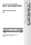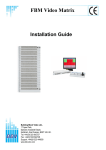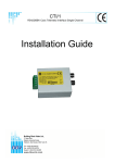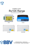
1
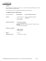
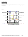
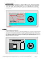
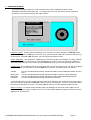
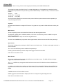
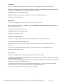
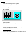
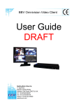
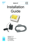
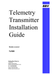
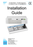
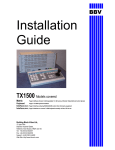
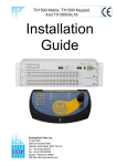
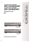
T-Command
Installation
Guide
Building Block Video Ltd.,
17 Apex Park,
Diplocks Industrial Estate,
Hailsham, East Sussex, BN27 3JU UK.
Tel: +44(0)1323 842727
Fax: +44(0)1323 842728
Support: +44(0)1323 444600
www.bbvcctv.com
1. PRE-INSTALLATION CHECKS AND SAFETY PROCEDURES
UNPACKING
Check Packaging - Upon taking delivery of the unit, inspect the packaging for signs of damage. If
damage has occurred, advise the carriers and/or the suppliers immediately.
Check Contents - Upon taking delivery of the unit, unpack the unit carefully and check that all the
items are present and correct. If any items are missing or damaged, contact your equipment dealer.
Retain Packaging - The shipping carton is the safest container in which to transport the unit.
Retain undamaged packaging for possible future use.
IMPORTANT SAFETY PRECAUTIONS
Read Instructions - All relevant safety, installation and operating instructions should be read
before attempting to install, connect or operate the unit.
Retain Instructions - All safety, installation and operating instructions should be retained for future
reference.
Heed Warnings - All warnings on the unit and in any relevant safety, installation or operating
instructions should be adhered to.
Cleaning - Unplug the unit from the power outlet before cleaning. Do not use liquid cleaners or
aerosol cleaners. Use a damp cloth for cleaning.
Attachments - Do not use attachments not recommended by the product manufacturer as they may
cause hazards.
Water and Moisture - Do not expose the internal electronics of this unit to water or dampness; for
example, in an unprotected outdoor installation, or in any area classified as a wet location.
Accessories - Do not attach this unit to an unstable stand, bracket or mount. The unit may fall,
causing serious injury to a person and serious damage to the unit.
Power Sources - This unit should be operated only from the Plug Top PSU Supplied. Refer to
operating instructions.
Power Connector - This unit is equipped with coaxial power connector mounted at the edge of the
PCB for low voltage power input. Do not attempt to alter this connector in any way.
Power Cord Protection - Power supply cords should be routed so that they are not likely to be
trapped, pinched or otherwise damaged by items in close proximity to them, Particular attention
should be paid to cords at plugs at the rear of the unit.
Overloading - Do not overload outlets and extension cords, as this can result in fire or electric
shock.
Object and Liquid Entry - Never push objects of any kind into the unit, as they may touch
dangerous voltage points or short out parts that could result in fire or electric shock. Never spill
liquid of any kind on or inside the unit.
Servicing - Servicing of the unit should only be undertaken by qualified service personnel, as
opening or removing covers may expose you to dangerous voltages or other hazards.
TCOMMAND OPERATING INSTRUCTIONS V1.3 09-03-2009 V18 SOFTWARE.DOC
Page 2
Damage Requiring Service - Servicing by qualified personnel should be carried out under the
following conditions:
(a)
When the power-supply cord or plug is damaged.
(b)
If liquid has been spilled or objects have fallen into the unit
(c)
If the internal electronics of the unit have been exposed to rain or water
(d)
If the unit does not operate normally by following the operating instructions. Adjust only
those controls that are covered by the operating instructions, as improper adjustment of other
controls may result in damage and will often require extensive work by a qualified technician to
restore the unit to normal operation.
(e)
If the unit has been dropped or the enclosure is damaged.
(f)
If the unit exhibits a distinct change in performance. This indicates a need for service.
Replacement Parts - If replacement parts are required, ensure that only replacement parts
recommended by the product manufacturer are used.
Safety Check - Upon completion of any service or repairs to the unit, safety checks should be
performed to ensure that the unit is in proper operating condition.
Pre-installation Checks - It is recommended that the unit be bench-tested prior to installation on
the site.
Safety During Installation or Servicing - Particular care should be taken to isolate the Matrix or
Pick A Point in order to prevent operation while engineering work is being carried out on the TCommand.
Adhere to Safety Standards - All normal safety precautions as laid down by British Standards and
the Health and Safety at Work Act should be observed.
WARNING
TO PREVENT DANGER OF FIRE OR SHOCK, DO NOT
EXPOSE THE INTERNAL COMPONENTS OF THIS
EQUIPMENT TO RAIN OR MOISTURE.
The “lightning flash with arrowhead” symbol inside an equilateral triangle is used to warn the user of
this equipment that there are sufficiently high voltages within the enclosure to constitute a risk of
electric shock.
The “exclamation point” symbol inside an equilateral triangle is used to alert the user of this
equipment to important operating and maintenance (servicing) instructions in the literature
accompanying the appliance.
TCOMMAND OPERATING INSTRUCTIONS V1.3 09-03-2009 V18 SOFTWARE.DOC
Page 3
2. INTRODUCTION
GENERAL
The T-Command is designed to allow control of a variety of BBV Video Matrices, Pick A Point
rd
systems & a Variety of 3 Party DVRs.
The T-Command is a user friendly keyboard with simple to understand icons.
T-COMMAND TECHNICAL SPECIFICATION
Power Requirements:
9VDC @ 500mA
( plug mounted PSU provided)
Features:
• 2 Serial data ports
i RS232 or RS422/485 selectable.
ii RS422/485
• 4.5” X 3.5” LCD.
• 3 Axis Joystick.
Engineering Facilities:
• On site screen calibration.
• On site Joystick calibration.
• On site Configuration when being used with a Tx1500 in a retail
application
• On Site Flash Programmable.
Dimensions (unboxed):
• Width: 140 mm
• Length: 265 mm
• Height: 150 mm
Weight:
• 3.6Kg
Temperature range:
• 0° Celsius to +40° Celsius
TCOMMAND OPERATING INSTRUCTIONS V1.3 09-03-2009 V18 SOFTWARE.DOC
Page 4
3. INSTALLATION
OPERATING VOLTAGE
The T-Command requires 9VDC @ 500mA the LCD back light requires the full 9VDC to start. If the unit is
supplied with less the keyboard will light and then fail. The T-Command can also be supplied with power by
the CAT 5 cable fig 1.
Fig. 1 Note the connections below are at the T-Command & the Tx would be Rx at the MATRIX / CPU end of
the cable.
WHITE/BLUE
BLUE
RxB (FROM MATRIX / CPU) = 5
4 = RxA (FROM MATRIX / CPU)
GREEN
WHITE/GREEN
TxB (TO MATRIX / CPU) = 6
3 = TxA (TO MATRIX / CPU)
WHITE/BROWN
0V SUPPLY = 7
2 =+9Vdc SUPPLY
BROWN
0V SUPPLY = 8
ORANGE
WHITE/ORANGE
1 =+9Vdc SUPPLY
White/Blue, Blue, White/Orange, Orange, White/Green, Green, White Brown, Brown,
are the recommended CAT5 & 6 Colours
TCOMMAND OPERATING INSTRUCTIONS V1.3 09-03-2009 V18 SOFTWARE.DOC
Page 5
Fig. 2 Rear view of the T-Command Keypad.
4. DATA CONNECTIONS
The T-Command has two serial data ports both support RS422. The 1st port is labelled as KEYBOARD
this is dedicated for use with BBV equipment. The second is labelled as AUXILIARY this port is for
further development and not defined in this manual. The T-Command is supplied with one CAT5 Patch
Cable and one break out box. The Break out box enables the keypads to be installed over the site
without cutting Patch cables.
Fig. 3 Example of RS422 Keypad wiring.
BBUS maximum distance 1200M
Tx Data (FROM CPU)
Rx Data (TO CPU)
0V
RJ45 patch cable max length = 2M
+9Vdc
0V
+9Vdc
RJ45 patch cable max length = 2M
T-Command Keypad 1
BBUS Un-Terminated
1-4 = Keyboard Address
5&6 = Keyboard (BBUS) port termination
7&8 = Auxiliary port termination
RJ45 patch cable max length = 2M
T-Command Keypad 2
BBUS Terminated
ON
ON
1 2 3 4 5 6 7 8
1 2 3 4 5 6 7 8
TCOMMAND OPERATING INSTRUCTIONS V1.3 09-03-2009 V18 SOFTWARE.DOC
Page 6
Fig. 4 Internal view of the T-Command keypad.
Port 1 RS232 mode
RJ45 CONNECTIONS
Port 1 RS422/485 mode
RS422/485 mode
1 - OPTIONAL +9V SUPPLY
2 - OPTIONAL +9V SUPPLY
3 - TxB DATA
4 - RxA DATA
5 - RxB DATA
6 - TxA DATA
7 - Gnd (0V)
8 - Gnd (0V)
RS232
RS232
RS422/485
RS422/485
COLOUR
Orange/White
Orange
Green/White
Blue
Blue/White
Green
Brown/White
Brown
RS232
RS232 mode PORT 1 ONLY
1 - +9V SUPPLY
2 - +9V SUPPLY
3 - NOT CONNECTED
4 - TXD (TRANSMIT)
5 - NOT CONNECTED
6 – RXD (RECEIVE)
7 - Gnd(0V)
8 - Gnd(0V)
RS422/485
SW1
Touchscreen
dx1_V17.mot
PROG LINK
L1
Fig.
5
Address
switch settings.
and
SW 1
Termination
1-4 = Keyboard Address
5&6 = Keyboard (BBUS) port termination
7&8 = Auxiliary port termination
1
2
3
4
5
6
7
8
9
10
11
12
13
14
15
16
SW 1
SW 2
SW 3
SW 4
(1)
OFF
ON
OFF
ON
OFF
ON
OFF
ON
OFF
ON
OFF
ON
OFF
ON
OFF
ON
(2)
OFF
OFF
ON
ON
OFF
OFF
ON
ON
OFF
OFF
ON
ON
OFF
OFF
ON
ON
(4)
OFF
OFF
OFF
OFF
ON
ON
ON
ON
OFF
OFF
OFF
OFF
ON
ON
ON
ON
(8)
OFF
OFF
OFF
OFF
OFF
OFF
OFF
OFF
ON
ON
ON
ON
ON
ON
ON
ON
SW 5
PORT 1
RX
120R
ON
ON
ON
ON
ON
ON
ON
ON
ON
ON
ON
ON
ON
ON
ON
ON
SW 6
PORT 1
TX
120R
ON
OFF
ON
ON
ON
ON
ON
ON
ON
ON
ON
ON
ON
ON
ON
ON
TCOMMAND OPERATING INSTRUCTIONS V1.3 09-03-2009 V18 SOFTWARE.DOC
SW 7
PORT 2
RX
120R
ON
OFF
ON
ON
ON
ON
ON
ON
ON
ON
ON
ON
ON
ON
ON
ON
SW 8
PORT 2
TX
120R
ON
ON
ON
ON
ON
ON
ON
ON
ON
ON
ON
ON
ON
ON
ON
ON
Page 7
5. POWER UP SCREEN
When the T-Command is powered up you will see the Boot up screen. This will give important
configuration information. The Software Version will be very important when you call Tech Support
+44 (0) 1323 444600. The Keyboard Type will depend on the application you are using the TCommand for. There are a number of options available. Menu access will be necessary to change
the Keypad Type.
6. SETUP
T-Command Keypad Configuration.
In order to configure the T-Command you will need to power down the T-Command and wait 10 seconds.
Twist the joystick fully clockwise then push it to the top right (tilt up and pan right) then plug the power
cord back into the T-Command. You will the be asked to Pan Right to enter PIN. This will then bring you
to the PIN number screen. The Password is 2325. You will then enter the Engineering Menu.
If you are having trouble seeing the screen it is at this point you can adjust the Contrast. This is done by
twisting the zoom knob on the joystick.
Keypad Configuration
Pan right to enter PIN
EXIT
BIAS
31
PAN32768
TILT33024
ZOOM 125
X 648
Y 648
BBV T Command
TCOMMAND OPERATING INSTRUCTIONS V1.3 09-03-2009 V18 SOFTWARE.DOC
Page 8
7. ENGINEERING MENU
The Engineering Menu allows you to do a number of key things, Calibrate Joystick, Screen
Calibration and select the Keypad Type. To navigate the menu you will need to use the joystick tilt
up & down to move up & down then pan right to select.
Calibrate Joystick - this will allow re-calibrating of the Joystick. You will go straight to a YES NO screen
you will need to press the YES key to continue. Then you will need to follow the instructions that come up
on the screen. Or pressing NO will return you to the Engineering Menu screen.
Screen Calibration - this will allow re-calibrating the Touch Screen part of this keypad. You will go straight
to a YES NO screen you will need you press the YES key to continue. Then you will need to follow the
instructions that come up on the screen. Or pressing NO will return you to the Engineering Menu screen.
Keypad Type – this will allow to select the type of keypad you wish the keypad to be. You will go straight to
a YES NO screen you will need to press the YES key to continue. You will be given four options:
TX1500
Dixons DX1
Ganz DVR
Fast DVR
This is to be selected when being used with the BBV Tx1500, FBM Video Matrix & Pick A
Point.
This is to be selected when being used with the BBV Tx1500 in a retail application.
This is to be selected when being used with the Ganz DVR GANZ ZR-DH1621NP.
This is to be selected when being used with the Fast DVR.
To navigate the menu you will need to use the joystick tilt up & down to move up & down then pan right to
select you will then be shown the YES NO screen to confirm your selection. Then the T-Command will reboot and show the power up screen. Or pressing NO will return you to the Engineering Menu screen.
Display Timeout – To reduce electrical power usage, the backlight for the touch screen display can be
automatically turned off after a period of no use. This menu option allows the display to timeout or for the
display to be on all the time.
TCOMMAND OPERATING INSTRUCTIONS V1.3 09-03-2009 V18 SOFTWARE.DOC
Page 9
8. Tx1500
In this Keypad Type you will be able to control the BBV Tx1500; FBM Video Matrix & Pick A Point below is
the main screen. On this screen you can carry out basic matrix functions ie Camera, Monitor, Preset selection
& Pan, Tilt, Zoom Functions.
To select a Monitor you will need to press a number pad ie 8 followed by MONITOR pad. This will select
monitor 8 & it will update the 3 digit display next to the Mon legend.
To select a camera you will need to press a number pad ie 6 followed by CAMERA pad. This will select
camera 6 & it will update the 3 digit display next to the Cam legend.
To select a preset you will need to press a number pad ie 4 followed by PRESET pad. This will send the
camera selected to preset 4.
Cam
000
Mon
001
1
2
3
MENU
4
5
6
+
7
8
9
-
CAMERA
0
MONITOR
PRESET
BBV T Command
If you press MENU you will move on to the next screen this gives you more PTZ functions. To start a Patrol
you will need to press 1 or 2 followed be PATROL pad. This will select one of the two patrols. There is also
the RELAY pad this controls the relay on the front of the Tx1500 Matrix (only) or on the individual Alarm
Cards refer to the Tx1500 Manual.
Cam
000
Mon
001
1
2
3
MENU
4
5
6
AUTOPAN
7
8
9
LIGHTS
CAMERA
0
RELAY
PATROL
BBV T Command
TCOMMAND OPERATING INSTRUCTIONS V1.3 09-03-2009 V18 SOFTWARE.DOC
Page 10
If you press MENU you will move on to the next screen this gives more Matrix based controls.
To start a sequence on the selected monitor you will need to press the SEQ pad.
To acknowledge stacked alarms you will need to press the ALARM pad.
To enter the Tx1500 menu you will need to press AND HOLD the PROGRAM pad.
To enter the Tx1500 COAX menu you will need to press AND HOLD the # pad for 2 seconds.
Cam
000
Mon
001
1
2
3
MENU
4
5
6
SEQ.
7
8
9
ALARM
CAMERA
0
#
PROGRAM
BBV T Command
TCOMMAND OPERATING INSTRUCTIONS V1.3 09-03-2009 V18 SOFTWARE.DOC
Page 11
9. DX1 DIXONS
In this Keypad Type you will be able to control the BBV Tx1500,when the matrix is set up in DIXONS
MODE Ref, to BBV Tech Support +44 (0) 1323 444600. On this screen you can carry out basic matrix
functions ie Camera, & Preset selection including Pan, Tilt, and Zoom Functions.
To select a camera you will simply need to press a number pad ie 6, this will select camera 6, if you
require cameras 13- 24 press the 13-24 pad.
To select a preset you will need to press a number pad ie 4 followed be PRESET pad. This will send the
camera selected to preset 4.
To save a preset you will need to press AND HOLD the PRESET pad; this will then bring you to the PIN
number screen. The Password is 6181. You will then be given 8 pads these correspond to presets 1
through to 8.
When the Tx1500 is set up in DIXONS MODE the T-Command is locked to the Monitor number that
corresponds to the T-Command address. In plain KBD 1 will only control Monitor 1 & KBD 2 will only
control Monitor 2.
1
2
3
4
5
6
7
8
9
10
11
12
SEQ
FOCUS
PRESET
13-24
BBV T Command
If you press 13-24 you will move on to the next screen this gives more camera numbers.
1
2
3
4
5
6
7
8
9
10
11
12
SEQ
FOCUS
PRESET
1 - 12
BBV T Command
TCOMMAND OPERATING INSTRUCTIONS V1.3 09-03-2009 V18 SOFTWARE.DOC
Page 12
Within the DX1 there is an Engineering Menu, to access this menu you will need to press AND HOLD the
PRESET pad, This will then bring you to the PIN number screen. The Password is 2325.
Calibrate Joystick - this will allow re-calibrating the Joystick. You will go straight to a YES NO screen you
will need you press the YES key to continue. Then you will need to follow the instructions that come up
on the screen. Or pressing NO will return you to the DX1 Engineering Menu screen.
The Multiscreen Input Function allows the on site DVR monitor output to be fed back into a spare camera
input of the Matrix. You will go straight to a YES NO screen you will need you press the YES key to
continue. Then you will need to press the + or – pads until you have the correct camera input selected.
Or pressing NO will return you to the DX1 Engineering Menu screen.
Screen Calibration - this will allow re-calibrating the Touch Screen part of this keypad. You will go
straight to a YES NO screen you will need you press the YES key to continue. Then you will need to
follow the instructions that come up on the screen. Or pressing or pressing NO will return you to the DX1
Engineering Menu screen.
Config PTZ/Static - will allow toggle between DOME or STATIC you will go straight to a YES NO screen
you will need you press the YES key to continue. Then you can set up each camera input individual. Or
pressing NO will return you to the DX1 Engineering Menu screen.
Access TX1500 Menus - will allows full access to the Tx1500 menu without the normal Tx1500 password
To navigate the Tx1500 menu you will need to use the joystick tilt up & down to move up & down then
pan right & left to move right & left press + pad to select within the Tx1500 menu.
Max. Camera - this will allow to select the maximum number of cameras the T-Command can Display on
the touch screen. You will go straight to a YES NO screen you will need you press the YES key to
continue. Then you are given 3 options 1 – 24, 1 – 36 or 1 - 48. To navigate the menu you will need to
use the joystick tilt up & down to move up & down then pan right to select Or pressing NO will return you
to the DX1 Engineering Menu screen.
Keypad Type – this will allow to select the type of keypad you wish the keypad to be. You will go straight
to a YES NO screen you will need you press the YES key to continue. You will be given four options:
TX1500
Point.
Dixons DX1
Ganz DVR
Fast DVR
This is to be selected when being used with the BBV Tx1500, FBM Video Matrix & Pick A
This is to be selected when being used with the BBV Tx1500 in a retail application.
This is to be selected when being used with the. GANZ ZR-DH1621NP.
This is to be selected when being used with the Fast DVR.
TCOMMAND OPERATING INSTRUCTIONS V1.3 09-03-2009 V18 SOFTWARE.DOC
Page 13
To navigate the menu you will need to use the joystick tilt up & down to move up & down then pan right
to select you will then be shown the YES NO screen to confirm your selection. Then the T-Command
will re-boot and show the power up screen. Or pressing or pressing NO will return you to the DX1
Engineering Menu screen.
Display Timeout – To reduce electrical power usage, the backlight for the touch screen display can be
automatically turned off after a period of no use. This menu option allows the display to timeout or for the
display to be on all the time.
TCOMMAND OPERATING INSTRUCTIONS V1.3 09-03-2009 V18 SOFTWARE.DOC
Page 14
10 Ganz DVR
Notes on using Touch Screen Keypad (V9 software) with GANZ ZR-DH1621NP
The keypad connects to the DVR via the T-command keyboard port. The keypad only transmits since the
DVR protocol at present does not provide any useful feedback data (i.e. status info etc.). Connections are as
follows: Keypad
Pin 3(+TX)
Pin 6(-TX)
DVR
Pin 2(+RX)
Pin 3(-RX)
The keys that are displayed on the screen mainly mimic DVR front panel controls but some special keys
control the keypad screens.
Joystick.
At present the DVR does not support PTZ control. The joystick is only used for DVR OSD menu control (see
later).
Main Screen.
This is the primary screen to access all DVR functions and other keypad screens.
The DISPLAY, USER, SPOT, SEARCH, MENU, PTZ, PLAY and AUTO keys mimic the DVR front panel
controls. In addition the
SPOT, MENU and PLAY keys activate other keypad screens.
The UNIT and CAMERA keys only select other keypad screens, which mimic the 16 DVR front panel keys.
Spot Screen.
This screen is displayed by pressing the SPOT button on the Main screen. The Spot mode toggle command is
sent to the DVR.
The 1 to 16 and AUTO keys mimic the DVR front panel keys.
Pressing the Main MON key sends the Spot mode toggle command to the DVR.
EXIT returns to the Main screen.
Menu Screen.
This screen is displayed after pressing the MENU key on the Main screen. The DVR OSD Menu display
toggle command is sent to the DVR.
The ^ v > < ENTER keys navigate the DVR OSD menus and mimic FF REW PLAY RPLAY ENTER front
panel keys.
In addition, the Joystick can be used to control the menus. Tilt up mimics FF. Tilt down mimics REW. Pan
right mimics PLAY. Pan left mimics RPLAY. Twist clockwise mimics ENTER. Twist anticlockwise mimics
MENU.
CAMERA selects the Camera Select screen.
MENU toggles the DVR OSD Menu display but does not change the keypad-displayed screen.
EXIT returns to the Main screen.
TCOMMAND OPERATING INSTRUCTIONS V1.3 09-03-2009 V18 SOFTWARE.DOC
Page 15
PTZ Screen.
This screen is displayed after pressing the PTZ key. The PTZ toggle command is sent to the DVR.
TOUR, AUTO, PTZ (toggle PTZ mode), IRIS, FOCUS keys mimic front panel although at present IRIS and
FOCUS are not supported in the DVR protocol and do not function.
CAMERA selects the Camera Select screen.
PRESET selects the Preset screen but does not active the DVR OSD Preset menu.
EXIT returns to the Main screen.
Play Screen.
This screen is displayed after pressing the PLAY key from another screen.
RW <<, STOP, FF >>, RPLAY <, PAUSE ||, PLAY > PANORAMA, FULLZOOM, DISPLAY and PIP mimic
the DVR front panel keys.
CAM selects the Camera Select screen.
PASSWORD selects the Password screen.
EXIT returns to the Main screen.
Camera or Unit Select Screen.
This screen is displayed after pressing the CAM, CAMERA or UNIT key on another screen.
1 to 16 keys mimic the DVR front panel keys.
When selected from the UNIT key the number key pressed selects the unit number of the DVR to be
controlled.
The number key pressed is displayed at the top of the keypad screen in the appropriate window.
EXIT returns to the Main screen.
Preset Screen
This screen is displayed after the PRESET key is pressed on the PTZ screen.
A Preset is selected by pressing the appropriate number keys followed by GOTO i.e. Press 2 then 7 followed
by GOTO to select Preset 27.
The selected Preset will be displayed at the bottom of the keypad screen before the GOTO key is pressed. If
this number is incorrect press CLEAR to clear.
To program/set a Preset first move the camera to the desired position. Then enter the desired numbers
followed by SET i.e. Press 3 then 5 followed by SET to program/set Preset 35.
Preset numbers greater than 99 will not be accepted or actioned
TCOMMAND OPERATING INSTRUCTIONS V1.3 09-03-2009 V18 SOFTWARE.DOC
Page 16
8
7
6
5
4
3
2
1
RJ45
GREEN
RED
BLUE
YELLOW
BLACK
1
2
NOT CONNECTED
3
BLACK
4
YELLOW
5
BLUE
6
RED
7
GREEN
8
Cable and RJ11 is a FARNELL subassembly.
Part number: 754-948
NOT CONNECTED
NOT CONNECTED
TCOMMAND OPERATING INSTRUCTIONS V1.3 09-03-2009 V18 SOFTWARE.DOC
NOT CONNECTED
NOT CONNECTED
BLACK
YELLOW
BLUE
GREEN
RED
NOT CONNECTED
WHITE IS
NOT USED
Fig. 6 interconnecting cable between T-Command keyboard port and Ganz DVR GANZ ZR-DH1621NP.
11 Ganz DVR CONNECTION INFORMATION
RJ11
WHITE
BLACK
RED
GREEN
YELLOW
BLUE
12 FAST DVR
Connection between T-Command (keyboard port) and FAST DVR COM port.
Note the T-Command port 1 will need to configured for RS232 refer to fig 4 page 7.
T-Command RJ45
GREEN (4)
BROWN PAIR (7 & 8)
FAST DB9-F
2 (RXD)
5 (GND)
Internal SW1 switch settings – ALL OFF.
LIVE - PTZ CONTROL
Cam
001
001
Mon
IRIS+
FOCUS+
AUX1
IRIS-
FOCUS+
AUX2
7
8
9
CAMERA
MONITOR
PRESET
REPLAY
BBV T Command
LIVE MODE – ON POWER UP.
This screen switches the DVR monitor into LIVE mode allowing camera selection and PTZ control using the
joystick. Focus and Iris, if supported, can be controlled using FOCUS +/- and IRIS +/-. AUX 1 and AUX 2 are
used to toggle PTZ auxiliary outputs.
GOTO PRESET POSITION
Press the PRESET pad followed by the GOTO pad.
Using the numeric pads to select the preset number required and then press the ENTER pad to recall the camera
to the preset. OR press the EXIT pad to ignore the preset command.
Example PRESET, GOTO, 3, ENTER. This will send the Camera to Preset 3.
SAVE PRESET POSITION
Press the PRESET pad followed by the SAVE pad.
Using the numeric pads to select the preset number required and then press the ENTER pad to save the current
position OR press the EXIT pad to ignore the save preset command.
Example PRESET, SAVE, 4, ENTER. This will save the new position as Preset 4.
TCOMMAND OPERATING INSTRUCTIONS V1.3 09-03-2009 V18 SOFTWARE.DOC
CHANGING CAMERA
Press the CAMERA pad then using the numeric pads to select the camera required and then press the ENTER
pad to select this new camera OR press the EXIT pad to keep with the original camera.
Example CAMERA, 4, ENTER. This will select camera 4.
CHANGING MONITOR
Press the MONITOR pad then using the numeric pads to select the monitor required and then press the ENTER
to select this new monitor or press the EXIT to keep with the original monitor.
Example MONITOR 2, ENTER. This will select monitor 2.
REPLAY/PLAYBACK MODE
Pressing the REPLY pad will switch the DVR into playback mode and the screen changes to the following layout.
Cam
001
Mon
001
<<REW
<PLAY
PLAY>
FF>>
BEGIN
SEARCH
PAUSE
END
CAMERA
LIVE
BBV T Command
The pads function similarly to a conventional VCR. The joystick is also used to fast forward and rewind by
moving the joystick RIGHT or LEFT. When PAUSED the joystick can be moved UP and DOWN to show next
and previous frames.
Press the CAMERA pad to change the current camera using the same procedure used in live mode.
TIME AND DATE SEARCH
Press the SEARCH pad and then use the numeric keys to select the specific time and date to view followed by
the ENTER pad.
The time and date must be entered in this format:
YEAR MONTH DAY HOUR MINUTE SECOND
For example to display time/date of 10 JULY 2005, 10:12.34 press the following keys.
SEARCH 20050710101234 ENTER
SWITCHING BACK TO LIVE
Press the LIVE pad to switch the DVR back into LIVE mode.
Other BBV products.
Product Description
camera desktop telemetry transmitter with BBV up-the-coax &
TX300 Single
20mA telemetry, Pan/Tilt/Lens & Lights
TX400 As TX300 inc Wash, Wipe, Autopan, 8 presets, preset patrol.
TX400DC As TX400 including joystick for proportional Pan/Tilt control.
8 or 16 camera, 2 monitor telemetry transmitter. Up to 2 keyboards.
up-the-coax and RS422 standard with options for alarm inputs and
TX1000 MK2 BBV
20mA telemetry.
Mid size matrix 16 – 96 camera, 8 monitor. Up to 4 control positions
& remote control) options for alarms, remote control, BBV upTX1500 (keyboard
the-coax and RS485 telemetry.
FBM range
RX100
RX100/BAX
RX200
RX300
RX400P
RX45X (AC)
RX55X (DC)
Multi RS485 protocol
and BBV up-the-coax
telemetry receivers
CTI16
STARCARD
STARCARD/CONVERTER
ACCESSORIES
Large size matrix. Configurable up to 4096 cameras and 64 monitor
outputs. Up to 16 control positions (keyboard & remote control) options
for alarms, remote control RS485/RS422 telemetry with various options.
Please call to discuss requirements.
Dome Interface with options to drive a large library of dome cameras.
BBV up-the-coax and 20mA telemetry.
Dome Interface with options to drive a large library of dome cameras.
BAXALL up-the-coax telemetry.
AC receiver for Pan only heads or static cameras, Wash/Wipe/Lights.
BBV up-the-coax and 20mA telemetry.
AC receiver for Pan/Tilt/Zoom/Focus/Iris Override and 1 Auxiliary
output. BBV up-the-coax and 20mA telemetry.
AC full function receiver. PTZFI 4 Auxiliary outputs, 16 presets. BBV
up-the-coax and 20mA telemetry.
Multiple RS485/422 and BBV up-the-coax controllable AC and DC
receivers. These receivers are controlled from an expanding range of
serial protocols as listed below. 110/230Vac supply. PTZFI, 64 presets,
preset patrol, 8 local alarm inputs, 12V 500mA supply output. OSD for
remote diagnostics. 3 Aux. outputs RX55X or 4 Aux. outputs RX45X.
Optional Privacy board.
BBV RS485, COAX & 20mA,
BAXALL COAX,
DENNARD RS485,
MOLYNX
PELCO P/D RS485,
VCL/HONEYWELL RS485,
PHILIPS/BOSCH RS485 (OPTIONAL BI-PHASE INPUT),
SENSORMATIC/AD RS422
VICON RS422
CIRRUS AUDIO MONITORING
Multi-protocol serial converter that gives up-the-coax control to 16
cameras. BBV RS422, Dennard RS485, Pelco P, Pelco D,
Philips/Bosch RS485/232, VCL RS485, Sensormatic RS422, Molynx,
Vicon
8 * RS485 output, 2 wire simples RS422, 4 wire full-duplex RS422, 2
wire half-duplex RS485.
Optional STARCARD/CONVERTER offering protocol conversion to
rd
drive an increasing range of 3 party protocols.
CTI/16 16 camera, RS422 to up-the-coax converter
TxLD (bidirectional RS422-RS232 converter)
98005 (bidirectional 20mA-RS232 converter)
AD RS422 (American Dynamics) protocol converters