1
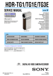
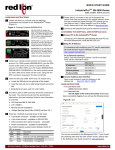
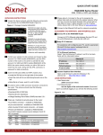
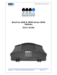
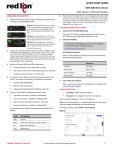
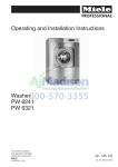
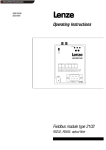
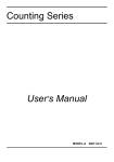
BT/SN/RAM 6000 Series
Hardware Manual
August 2014
www.redlion.net
Chapter 1
1.1
Specifications . . . . . . . . . . . . . . . . . . . . . . . . . . . . . . . . . . . . . . . . . . . . . . . . . . . . . . 5
1.1.1
1.1.2
1.1.3
1.1.4
1.1.5
1.1.6
Chapter 2
2.1
2.2
2.3
2.4
2.5
2.6
2.7
2.8
2.9
General Specifications . . . . . . . . . . . . . . . . . . . . . . . . . . . . . . . . . . . . . . . . . . . . . . . . . . . . . . . . . . 5
Mechanical Specifications BT/SN/RAM-6000. . . . . . . . . . . . . . . . . . . . . . . . . . . . . . . . . . . . . . . . . 7
Power Specifications and Consumption . . . . . . . . . . . . . . . . . . . . . . . . . . . . . . . . . . . . . . . . . . . . . 7
Indicator Lights (LED) . . . . . . . . . . . . . . . . . . . . . . . . . . . . . . . . . . . . . . . . . . . . . . . . . . . . . . . . . . 11
Data Interface Specifications: Serial, Ethernet & USB . . . . . . . . . . . . . . . . . . . . . . . . . . . . . . . . . 11
RESET Button Functions . . . . . . . . . . . . . . . . . . . . . . . . . . . . . . . . . . . . . . . . . . . . . . . . . . . . . . . 13
Hardware Installation . . . . . . . . . . . . . . . . . . . . . . . . . . . . . . . . 14
Mounting the BT/SN/RAM-6000 Series Modem . . . . . . . . . . . . . . . . . . . . . . . . . . 14
DIN Rail Mounting & Removal . . . . . . . . . . . . . . . . . . . . . . . . . . . . . . . . . . . . . . . . 14
Cellular Antenna . . . . . . . . . . . . . . . . . . . . . . . . . . . . . . . . . . . . . . . . . . . . . . . . . . . 15
Ethernet Cable . . . . . . . . . . . . . . . . . . . . . . . . . . . . . . . . . . . . . . . . . . . . . . . . . . . . . 16
USB Cable . . . . . . . . . . . . . . . . . . . . . . . . . . . . . . . . . . . . . . . . . . . . . . . . . . . . . . . . 16
Serial Cable . . . . . . . . . . . . . . . . . . . . . . . . . . . . . . . . . . . . . . . . . . . . . . . . . . . . . . . 16
Power Source. . . . . . . . . . . . . . . . . . . . . . . . . . . . . . . . . . . . . . . . . . . . . . . . . . . . . . 17
Thermal Performance and Considerations . . . . . . . . . . . . . . . . . . . . . . . . . . . . . . 17
Cleaning . . . . . . . . . . . . . . . . . . . . . . . . . . . . . . . . . . . . . . . . . . . . . . . . . . . . . . . . . . 18
Chapter 3
3.1
3.2
Product Overview . . . . . . . . . . . . . . . . . . . . . . . . . . . . . . . . . . . . 5
Service and Support Information . . . . . . . . . . . . . . . . . . . . . . 19
Service Information . . . . . . . . . . . . . . . . . . . . . . . . . . . . . . . . . . . . . . . . . . . . . . . . . 19
Product Support . . . . . . . . . . . . . . . . . . . . . . . . . . . . . . . . . . . . . . . . . . . . . . . . . . . 19
This manual applies to the following products:
BT/SN/RAM-6401
BT/SN/RAM-6421
BT/SN/RAM-660x
BT/SN/RAM-6621
BT/SN/RAM-680x
BT/SN/RAM-6821
BT/SN/RAM-670x
BT/SN/RAM-6721
Hardware Manual
2
INSTALLATION AND HAZARDOUS AREA WARNINGS
These products should not be used to replace proper safety interlocking. No software-based device (or any other solid-state device)
should ever be designed to be responsible for the maintenance of consequential equipment or personnel safety. In particular, Red
Lion disclaims any responsibility for damages, either direct or consequential, that result from the use of this equipment in any application.
All power, input and output (I/O) wiring must be in accordance with Class I, Division 2 wiring methods and in accordance with the
authority having jurisdiction.
Suitable for use in Class I, Division 2, Groups A, B, C and D hazardous locations, or non-hazardous locations only.
WARNING – EXPLOSION HAZARD – SUBSTITUTION OF COMPONENTS MAY IMPAIR SUITABILITY FOR CLASS 1, DIVISION 2.
WARNING – EXPLOSION HAZARD – WHEN IN HAZARDOUS LOCATIONS, DISCONNECT POWER BEFORE REPLACING OR WIRING MODULES.
WARNING – EXPLOSION HAZARD – DO NOT DISCONNECT EQUIPMENT UNLESS POWER HAS BEEN SWITCHED OFF OR THE AREA IS
KNOWN TO BE NONHAZARDOUS.
These products are operator interface units to be used within control panels. These devices are intended for use in Class I, Division 2,
Hazardous Locations, industrial control applications. The enclosure shall be suitable for the location.
A minimum IP54 rated enclosure is needed for ATEX unless an equivalent degree of protection is supplied by the location.
These products are to be used within control panels in hazardous locations. The enclosure shall be suitable for this location. Hotswapping is not for use in hazardous locations.
AVERTISSEMENTS POUR INSTALLATION ET ENDROITS DANGEREUX
Ces produits ne doivent pas être utilisés pour remplacer le verrouillage de sécurité approprié. Aucun dispositif basé sur un logiciel (ou
tout autre dispositif à l'état solide) devraient jamais être conçus pour être responsable de l'entretien de l'équipement consécutifs ou
la sécurité du personnel. En particulier, Red Lion décline toute responsabilité pour les dommages, directs ou indirects, résultant de
l'utilisation de cet équipement dans n'importe quelle application.
Tout courant, câblage entrée et sortie (I / O) doit être conforme aux méthodes de câblage à la Classe I, Division 2 et conformément à
l'autorité compétente.
Cet appareil est adapté pour utilisation en Classe I, Division 2, Groupes A, B, C, D endroits dangereux ou endroits non-dangereux.
AVERTISSEMENT – RISQUE D’EXPLOSION – LA SUBSTITUTION DE TOUT COMPOSANT PEUT NUIRE À LA CONFORMITÉ DE CLASSE I,
DIVISION 2
AVERTISSEMENT – RISQUE D’EXPLOSION – LORSQUE DANS DES ENDROITS DANGEREUX, DÉBRANCHEZ LE CORDON D'ALIMENTATION
AVANT DE REMPLACER OU DE BRANCHER LES MODULES.
AVERTISSEMENT – RISQUE D’EXPLOSION – NE DÉBRANCHEZ PAS L'ÉQUIPEMENT À MOINS QUE L'ALIMENTATION AIT ÉTÉ COUPÉE OU
QUE L’ENVIRONNEMENT EST CONNU POUR ÊTRE NON DANGEREUX.
Ces produits sont des unités d'interface opérateur qui doivent être utilisés à l'intérieur des panneaux de commande. Ces appareils
sont destinés à une utilisation en Classe I, Division 2, zones dangereuses, applications de contrôle industriel. L'enclos doit être adapté
à l’environnement.
Un boîtier IP54 minimum est nécessaire pour ATEX à moins qu’un degré équivalent de protection est fourni par l'emplacement.
Lorsque dans des endroits dangereux, ces produits doivent être utilisés dans des panneaux de contrôle. Pas de remplacement à chaud
des modules dans les zones dangereuses.
Hardware Manual
3
Statement of Limited Warranty
Red Lion, manufacturer of Red Lion products, warrants to Buyer that products, except software, manufactured by Red Lion
will be free from defects in material and workmanship. Red Lion’s obligation under this warranty will be limited to repairing or replacing, at Red Lion’s option, the defective parts within three (3) years of the data of installation, or within three
(3) years of the date of shipment from the point of manufacture, whichever is sooner. Products may be returned by Buyer
only after permission has been obtained from Red Lion. Buyer will prepay all freight charges to return any products to the
repair facility designated by Red Lion.
This limited warranty does not cover losses or damages which occur in shipment to or from Buyer or due to improper
installation, maintenance, misuse, neglect of any cause other than ordinary commercial or industrial applications. In particular, Red Lion makes no warranties whatsoever with respect to implied warranties or merchantability or fitness for any
particular purpose. All such warranties are hereby expressly disclaimed. No oral or written information or advice given by
Red Lion or Red Lion’s representative shall create a warranty or in any way increase the scope of this warranty.
This limited warranty is in lieu of all other warranties whether oral or written, expressed or implied. Red Lion’s liability
shall not exceed the price of the individual units, which are the basis of the claim. In no event shall Red Lion be liable for
any loss of profits, loss of use of facilities or equipment, or other indirect, incidental or consequential damages.
Hardware Manual
4
Specifications
Chapter 1 Product Overview
1.1
Specifications
1.1.1
General Specifications
Note: All specifications are subject to change. Consult the Red Lion website for more information.
CDMA EvDO.A models
•
Dual-band CDMA2000 EVDO Rev. A (with diversity)
•
Backward compatible with 1xRTT and IS95
GSM EDGE Models
Wireless interfaces
•
Quad-band 850/900/1800/1900 GSM
•
Backward compatible with Quad-band GPRS/UMTS
GSM HSPA Models
Peak Data Rates
Serial Interfaces
•
Quad-band 800/850/1900/2100 MHz WCDMA (with diversity)
•
HSDPA/HSUPA/HSPA
•
Backward compatible with GPRS/EDGE/UMTS
Download: CDMA - 3.1Mbps / EDGE - 384 kbps / HSPA - 7 Mbps
Upload: CDMA - 1.8 Mbps / EDGE - 120 kbps / HSPA - 5.76 Mbps
1x RS232 Serial DB9 115200 bps
USB Interfaces
BT/SN/RAM-6000 Series: 1x USB 2.0 mini B
LED Indicators
Power, WAN, Signal, RS232, GPS, Ethernet Link & Activity
Dimensions
Power Input
Power Consumption
BT/SN/RAM-6x0x: 120 x 96 x 32 mm (4.7 x 3.77 x 1.25"), 453g (1.0 lb)
BT/SN/RAM-6x21: 120 x 96 x 51 mm (4.7 x 3.77 x 2.00"), 500g (1.1 lb)
8 - 30 VDC (12 VDC nominal), Power over Ethernet on BT/SN/RAM-6x01EB
1x USB 2.0 Device mini
1x USB 2.0 Host type A
BT/SN/RAM-6000 Series
Operating Temp: -40 to +75°C*
Environmental
Shock & Vibration: IEC 60068-2-1/2/6/27/30, DNV 2.4 3.7/8/9, MIL-STD 810F/202G
Humidity: 5 to 95% non-condensing
MTBF BT6601EB 1530K Hours GB @ 40°C per MIL-HNDBK-217F2
MTBF BT6601 1,832K Hours GB @ 40°C per MIL-HNDBK-217F2
Hardware Manual
5
Specifications
Hazardous Locations - Class I, Div. 2, Groups A,B,C,D, ANSI / ISA12.12.01
Certifications
Electrical Safety - UL508/CSA22.2/14 (CUL)
EMC- FCC, part 15 and Industry Canada, ICES-003
PTCRB (GSM), CE, R&TTE, RoHS
Warranty
Compliances
3 years on design and manufacturing defects
The BT/SN/RAM-6000 Series products meet the following standards plus others:
Electrical Safety
These devices have been designed to meet the basic safety requirements of the following
standards:
•
CE per Low Voltage Directive and EIC 61010-1 (CE applies only to the -EU models.
Please contact Red Lion for availability)
•
UL508 (Industrial control equipment), ANSI/ISA 12.12.01 (Hazardous Locations)
•
CSA C22.2 No. 142 and No. 213 (per cUL)
EMC (emissions and immunity)
•
CE per the EMC directive (CE applies only to the -EU models. Please contact Red
Lion for availability)
•
IEC61000-6-2: Immunity in industrial environments
•
IEC 61000-6-4: Emmissions in industrial environments
•
FCC part 15 and ICES 003. See FCC statement on page 6.
•
EN 55022 (CISPR22)
This equipment has been tested and found to comply with the limits for a Class A digital
device, pursuant to part 15 of the FCC rules. These limits are designed to provide reasonable protection against harmful interference when the equipment is operated in a commercial environment. This equipment generates, uses, and can radiate radio frequency energy;
and if not installed and used in accordance with the instructions, may cause harmful interference to radio communications. Operation of this equipment in a residential area is likely
to cause harmful interference to radio communications, in which case the user will be
required to correct the interference at their own expense. Warning: Changes or modifications to this unit not expressly approved by the party responsible for compliance could void
the user's authority to operate the equipment.
Information to the user: If this equipment causes interference to radio or television reception, which can be determined by turning the equipment off and on, the user is encouraged
to try to correct the interference by one or more of the following measures: In order to
meet FCC emissions limits, this equipment must be used only with cables that comply with
IEEE 802.3. If necessary, the user should consult the dealer or an experienced radio/television technician for additional suggestions. The user may find the following booklet prepared by the Federal Communications Commission helpful: “How to Identify and Resolve
Radio-TV Interference Problems”. This booklet is available from: U.S. Government Printing
Office, Washington, DC 20402, Stock No. 004-000-00345-4
WEEE compliance
These devices comply with the WEEE directive. Do not throw away these devices in the
standard trash. Contact Red Lion regarding proper disposal.
RoHS compliance
These devices comply with the RoHS directive and are considered lead and other hazardous
substance free.
*+75°C See section 2.8 for thermal considerations.
Hardware Manual
6
Specifications
1.1.2
Mechanical Specifications BT/SN/RAM-6000
1.1.3
Power Specifications and Consumption
Power is supplied to the modem via:
•
4-pin Molex connector for the BT/SN/RAM-6x00 model
•
4-pin screw terminal for the BT/SN/RAM-6x01, BT/SN/RAM-6x01EB and BT/SN/RAM-6x21 models
•
DC 2.5 mm barrel plug for all BT/SN/RAM-6000 models
•
Power over Ethernet for all BT/SN/RAM-6x01EB models
Hardware Manual
7
Specifications
4-pin Molex Connector (BT/SN/RAM-6x00)
Power is supplied to the modem via the 4-pin Molex connector on the front panel for the BT/SN/RAM-6x00 models. The
pins are described as follows:
Pin
Name
Description
1
GND
Ground
2
POS
Power supply input (8 to 30 VDC)
3
IN
Digital and analog input
4
OUT
Digital output
Power Connector
(Facing Modem)
4-pin Screw Terminal (BT/SN/RAM-6xx1)
Power is supplied to the modem via the 4-pin Screw Terminal on the front panel for the BT/SN/RAM-6xx1 models. The
pins are described as follows:
Pin
Name
Description
1
GND
Ground
2
PWR+
Power supply input (8 to 30 VDC)
3
OUT
Digital output
4
IN
Digital and analog input
Power Connector
(Facing Front)
DC 2.5 mm Barrel Adapter
Power is supplied to the modem via the barrel adapter on the left side of all BT/SN/RAM-6000 series modems. The contacts are described as follows:
Pin
Name
Description
Sleeve
GND
Ground
Tip
PWR+
Power supply input (8 to 30 VDC)
Power Connector
(left side)
Warning: DC 2.5 mm barrel adapter shall not be used in hazardous locations.
Hardware Manual
8
Specifications
Power Specification
Power input to the modem is protected against reverse polarity and over-voltage. The modem's power consumption is as
follows:
Typical Power Consumption (Watts)
Standby
Transmitting
Minimum
Transmitting
maximum
BT/SN/RAM-6401
1.4
2.0
5.0
BT/SN/RAM-6421
2.7
3.4
6.4
BT/SN/RAM-660x
1.4
2.0
2.9
BT/SN/RAM-6621
3.0
3.6
4.5
BT/SN/RAM-680x
1.4
2.6
5.0
BT/SN/RAM-6821
3.0
4.2
6.6
BT/SN/RAM-670x
1.6
2.6
6.9
BT/SN/RAM-6721
3.3
4.3
8.7
Model
Wiring instructions are provided in the Hardware Installation section.
All modems are equipped with protection for reversed polarity and power surges over 33 volts. The modems are
equipped with an internal 3 Amp fuse.
Electrical Specifications and Pinout
1x Digital Output (DOUT)
Configuration : Open Collector, reference to ground
Absolute Maximum IDC: 500mADC (Vce = 750mVDC)
Absolute Maximum VDC: 30VDC (open circuit)
Absolute Minimum VDC: -0.4VDC (open circuit)
1x Digital Input (DIN)
Configuration : unisolated level detection, reference to ground
Active level : 1.6VDC to 30VDC
Inactive level : 0VDC to 1.3VDC
Absolute Minimum VDC: -0.3VDC
Absolute Maximum VDC: 33VDC
Leakage IDC at 5VDC : 150uADC
Hardware Manual
9
Specifications
1x Analog Input (Shared with Digital Input) (DIN/AI1)
Configuration : unisolated input, reference to ground
Resolution : 1024 (ADC 10-bit)
VDC per step : 4.8875855mVDC
Full scale level : 5VDC
Zero level : 0VDC
Absolute Minimum VDC: -0.3VDC
Absolute Maximum VDC: 8.3VDC
Leakage IDC at 5VDC : 265.96uADC TYPE
Modem Views
4-pin power connector
Screw-block power connector
Screw-block power connector
&
PoE power input
Ethernet Switch
•
BT/SN/RAM-6600
•
BT/SN/RAM-6800
•
BT/SN/RAM-6401*
•
BT/SN/RAM-6601
•
BT/SN/RAM-6801
•
BT/SN/RAM-6401EB*
•
BT/SN/RAM-6601EB
•
BT/SN/RAM-6801EB
•
BT/SN/RAM-6421*
•
BT/SN/RAM-6621
•
BT/SN/RAM-6821
*The BT/SN/RAM-64xx series modems are not equipped with a diversity antenna connector
Hardware Manual
10
Specifications
1.1.4
Indicator Lights (LED)
LED
Power
STATUS
CORRESPONDING STATE
OFF
Modem is powered off
ON
Modem is powered ON
FLASH
OFF
ON
Signal
Firmware error
No signal available or signal strength is below -100 dBm
Excellent signal strength = greater than -69 dBm
Fast: Every 300ms = -79 to -70 dBm
FLASH
Medium: Every 600ms = -89 to -80 dBm
Slow: Every 1200ms = -99 to -90 dBm
WAN
OFF
Cellular connection is not established
ON
Cellular connection is established - no network data activity
FLASH
RS232
Cellular connection is established - with network data activ ity
OFF
Serial connection is not established
ON
Serial connection is established - no data activity with host
*FLASH
Serial connection is established - with data activity with host
* Depending on Serial Application
1.1.5
Data Interface Specifications: Serial, Ethernet & USB
1.1.5.1
Ethernet Port
The modem's 10/100Mbps Ethernet port is compliant with the EIA-568 standard. The modem's ports are autosensing so
they can be used with either a straight or crossover RJ45 cable to connect to host ports.
The BT/SN/RAM-6x21 features a 5-port Ethernet switch allowing connectivity to multiple local devices.
1.1.5.2
USB Device Port
This is a USB 2.0 Device interface on a Mini B (BT/SN/RAM-6xxx) connector. It offers Ethernet-over-USB functionality using
the RNDIS driver for Windows 7, Windows XP and Windows Vista Operating systems only. The RNDIS driver must be
installed before the USB interface can be used. The driver and instructions can be obtained at www.redlion.net.
1.1.5.3
Serial Port (DB9)
The modem's serial port is an RS232 DCE, compliant with EIA-232 standard. The connector used is DB9 female and is
shown in the illustration below.
Serial connector (looking at front of modem)
Our RAM/SN modems have a standard RS232, serial interface with a DB9 connector style. The modems are DCE (Date
Communication Equipment) devices.
Hardware Manual
11
Specifications
Connect a DTE device to a DCE device using a straight pin-for-pin connection cable. to connect two DCE devices, use a null
modem cable which crosses the ‘transmit’ and ‘receive’ lines in the cable. An example of a DTE device is a computer. Most
other devices are DCE types.
Serial Port Pin-Out:
9 pin connector on the modem (DCE)
Female
RS232 DB9
Pin Number
Direction of signal:
1
Carrier detect (CD) Outgoing signal
2
Received data (RX) Outgoing data
3
Transmitted data (TX) Incoming data
4
Data terminal ready (DTR) Incoming handshaking signal
5
Signal ground
6
Data set ready ( (DSR) Outgoing handshaking signal
7
Request to send (RST) Incoming flow control signal
8
Clear to send (CTS) Outgoing flow control signal
9
Ring Indicator (RI) Outgoing signal
The TX (pin 3) wire is the one through which data from an attached device is transmitted to the modem. The RX (pin 2)
wire is the one on which data is transmitted by the modem.
RTS and CTS are handshaking signals that complement one another by handling flow control. RTS and CTS wires are used
when hardware flow control is enabled in both the modem and an attached device. On the other hand, software flow control uses special control characters transmitted from an application to a device attached to the modem. When software
flow control is implemented, the RTS and CTS lines ar not used.
DTS and DSR are also handshaking signals that are used to simply confirm that a device is attached and is turned on. DTR/
DSR is rarely used as flow control signals when RTS/CTS is used.
Connecting the modem to a DCE:
In order to connect a modem to another DCE device, a null modem cable configuration is required. If flow control is not
necessary i.e. no handshaking is required, the only pins to be used are TX, RX and GND. TX and RX have to be crossed
between the modem (DCE) and the other DCE device. GND is connected to GND. Disable flow control on the modem and
be sure that the attached device does not check for any of the handshaking signals. Below is an example diagram.
Hardware Manual
12
Specifications
In the event that full handshaking is required, all handshaking signals should be cross-connected, i.e. RTS/CTS have to be
crossed and DTR/DSR have to be crossed. In addition, TX and RX signals have to be crossed. Below is an example diagram.
For further serial wiring information, refer to Chapter 2 in this manual.
1.1.6
RESET Button Functions
Mode
Pattern
Description
Hard Reset
Press and hold for less than 3 seconds
Standard Reboot
Factory Restore
FW Upgrade
USB Pass-Through
Hardware Manual
Press and hold between 3 and 10 seconds
RS232 LED flashes quickly
Press and hold between 10 and 15 seconds
WAN LED flashes quickly
Press and hold for longer than 15 seconds
Signal LED flashes quickly
This option is implemented in SN version 3.09 and
higher. To restore default settings for older versions, rerun the SN Reflashing procedure found at
www.redlion.net
Puts the modem in advanced firmware upgrade
mode by restarting the modem and running the
bootloader only. Do not use this mode unless
instructed to by Red Lion Technical Support.
Puts the modem in main pass-through mode to the
RF module, allowing CCT provisioning and PST support. Do not use this mode unless instructed to by
Red Lion Technical Support.
13
Mounting the BT/SN/RAM-6000 Series Modem
Chapter 2 Hardware Installation
2.1
Mounting the BT/SN/RAM-6000 Series Modem
There are three different ways to mount a BT/SN/RAM-6000 series modem:
•
Horizontally using two #6 screws pan or fillister head onto its horizontal mounting feet
•
Vertically using two #6 screws pan or fillister head onto its vertical mounting feet
•
Vertically using a DIN rail clip
Note: Allow enough room to route the Ethernet, serial, I/O and other cables.
2.2
DIN Rail Mounting & Removal
The BT/SN/RAM-6000 series has a DIN rail clip pre-mounted to the back of the unit. To panel
mount the unit, the clip can be removed easily by removing the three (3) screws holding it in place.
See the image at right for reference.
The DIN clip has an integral spring mechanism that keeps it securely attached to the rail. Refer to
the diagrams below for how to mount and remove the unit to a standard EN50022 DIN rail.
Note: For best performance it is recommended that a DIN rail spacer (such as an end clamp) be
used between the RTU and adjacent devices. This will leave an air gap for best heat dissipation off of the case.
Mounting Instructions
Recommended DIN rail mounting steps:
1. Hook the top back on the DIN rail clips on the unit over the DIN
rail.
2. Push the bottom of the unit towards the DIN rail unit it snaps
into place.
Hardware Manual
Removal Instructions
Recommended DIN rail removal steps:
A. Push the whole unit down to free the bottom of the DIN rail clip.
See blue circle areas.
B. Pull the bottom of the unit away from the DIN rail.
C. Unhook the top of the unit and remove it from the DIN rail.
14
Cellular Antenna
2.3
Cellular Antenna
The selected cellular antenna(s) must meet the following specifications:
•
Maximum rated gain of 7.5 dBi for Cellular band, 3 dBi for PCS band, 5.5 dBi for LTE Band 4, and 9 dBi in the LTE
band 17 for RF exposure purposes of 2.1091.
•
Frequency bands:
•
LTE: (B17) 700 MHz & (B4) 1700 MHz
•
CDMA: Dual-band 800 & 1900 MHz
•
EDGE: 850/1900/900/1800 MHz
•
HSPA: 850/1900/2100 MHz
•
Nominal 50 ohm impedance
•
Voltage Standing Wave Ratio (VSWR) less then 2.5:1
•
Male SMA connector
The length of the antenna cable may affect the signal strength. Choose the appropriate cable type and length. The table
below provides can help pre-determine the loss to expect.
Cable Type
Loss per 100 feet
8216 (RG58)
31 dB
8267 (RG213)
7.6 dB
LMR-400
3.9 dB
LMR-500
3.15 dB
LMR-600
2.5 dB
LMR-1200
1.26 dB
Per FCC requirements the antenna gain including cable loss must not exceed 7.5 dBi in the Cellular band, 3 dBi in the PCS
band, 5.5 dBi for LTE Band 4, and 9 dBi in the LTE Band 17 for RF exposure purposes of 2.1091. The antenna(s) used for this
transmitter must be installed to provide a separation distance of at least 20 cm from all persons. The antenna(s) used for
this transmitter must not be co-located or operating in conjunction with any other antenna or transmitter except in
accordance with FCC multi-transmitter evaluation procedures.
Installation and Verification
When installing the antenna, follow the FCC and Industry Canada guidelines and keep the following in mind:
•
Mount the antenna(s) at least 30 cm (12 inches) from other antennas
•
Do not install the antenna in a closed metallic enclosure (such as a cabinet or the trunk of a car).
Once a modem has a signal, the Signal LED indicator will start flashing according to the signal strength. Additionally, the
Web Interface can display the received signal strength (RSSI) on the status page. The modem should have at the very least
one bar of signal strength.
Hardware Manual
15
Ethernet Cable
Antenna Diversity
The Red Lion 6000 series modems except for the BT/SN/RAM-64xx series have two antenna connectors available, labeled
Antenna and Diversity.
•
Antenna: This is the main antenna that is used for data transmission. It is mandatory to have the Antenna port
connected to an antenna.
•
Diversity: This is the diversity antenna, used to improve on the signal strength obtained from the main antenna.
This antenna is not mandatory however it will improve throughput in low signal and fringe areas.
Diversity/MIMO
This is the diversity or second LTE antenna, used to improve on the signal strength obtained from the main antenna. This
antenna is not mandatory for 3G, however it will improve throughput in low signal and fringe areas. Diversity is a transmission technique that consists of using two separate antennas to achieve the most robust cellular signal possible. Diversity will help achieve fast, reliable data throughput in applications that require a high amount of bandwidth. This antenna
is highly recommended for LTE.
To get the best performance, the Diversity antenna should be placed at a minimum of 5/8 of a wave length away from the
other antenna. Therefore, the minimum spacing for antennas in the 800 MHz frequency is 5/8 * 13.5" = 8.5". The diversity antenna can be spaced further away than this, ideally in increments of 13.5": 22", 35", etc. For a 1900 MHz only network, the optimal distance would be 5/8 * 6.2" = 4". Orienting the antennas differently from one another may also
improve performance, particularly when the antennas are close together.
2.4
Ethernet Cable
If you are connecting to the modem via the Ethernet port, you will need a straight or crossover category 5 cable with two
8-pin RJ45 connectors on each end.
To visually confirm that Ethernet cabling was done properly, check the LED indication on the Ethernet port located at the
rear panel of the modem. The Link LED should be on when the right cable is used.
2.5
USB Cable
This is an Ethernet-over-USB connection which behaves like an Ethernet connection. It can only be connected to a PC with
Windows 7, Windows XP or Windows Vista installed. If you are connecting to the modem via the USB port, you will need
a Type A plug to Type B mini plug USB cable for the BT/SN/RAM-6000 series modems. In order for the USB connection to
work, you need to install the Sixnet RNDIS USB driver which is available at www.redlion.net.
2.6
Serial Cable
The modem has all its serial port pins enabled. If all the pins are enabled on the attached serial device, it is important to
know whether the device is using DTE or DCE as a communication mode.
The modem is a DCE device, so use a straight-through serial cable between the modem and a DTE device such as a terminal. Use a NULL modem cable adapter between the modem and a DCE device such as another modem.
Hardware Manual
16
Power Source
If using custom wiring or if some pins are disabled, follow the guidelines below. The wiring will vary depending on
whether the attached serial device is a DTE or DCE.
For more information on Serial ports, refer to the Serial Port section in Chapter 1 of this manual.
2.7
Power Source
IMPORTANT
Any installations involving electrical wiring and connections should be done by someone who is experienced in this field.
As described in the Power specifications and consumption section, the modem can be powered using:
•
4-pin Molex connector for the BT/SN/RAM-6x00 models
•
4-pin screw terminal for the BT/SN/RAM-6x01, BT/SN/RAM-6x01EB and BT/SN/RAM-6x21 models
•
DC 2.5mm round plug for all models
•
PoE (Power over Ethernet) for BT/SN/RAM-6x01EB models
WARNING: DC 2.5 mm barrel adapter shall be used in hazardous locations.
Powering up the modem
The modem will power up as soon as an 8 to 30 VDC voltage is applied to one of its power inputs and shuts off when this
input voltage is below 4 VDC.
Testing the power connection
Check the PWR light on the modem: if it is turned on then the modem is powered. If it's off, then review the installation
procedures, or contact Red Lion Technical Support for further assistance.
2.8
Thermal Performance and Considerations
These units are rated for operation from -40 to +75°C when the proper thermal considerations are taken into account.
Please refer to the following information to maximize the performance of these units when they are operated under
extreme temperatures.
Hot Operating Conditions:
These units have many modes of operation which can cause the power consumption and corresponding heat dissipation
to vary greatly. This factor, along with others, can affect the performance and longevity of the unit. These units are rated
for operation up to +75°C in typical applications where the wireless communication (cellular and/or Wifi) is moderate*.
Hardware Manual
17
Cleaning
The maximum ambient temperature rating is further defined as follows:
•
60°C maximum for continuous operation:
•
•
•
The ambient temperature is defined as the temperature of the air immediately surrounding the unit.
For best performance and longevity, try to keep the ambient air temperature at or below 60°C as much as possible.
75°C for short term operation:
• Short term is defined as 4 hours or less, per day.
• Running at temperatures above 60°C for extended periods of time may reduce the performance and longevity of the
unit.
• Reduced wireless performance may occur when operating above +60°C.
* The above ratings are based on moderate wireless communications. If your wireless communications is atypically high
or frequent then the maximum ambient operating temperature may be reduced. The wireless circuit(s) in these units
may shutdown to protect from permanent damage when the internal circuitry temperature becomes extreme (typically
around 95°C but may vary depending on model). If this condition is occurring in your application then you need to do one
of the following:
• Reduce the ambient operating temperature which is the temperature of the air surrounding the outside of the
unit. Here are some suggestions on how to reduce the temperature:
• Make sure other hot devices are not mounted immediately adjacent or below the unit. It is recommended to use a DIN
rail spacer between adjacent units so heat cannot transfer due to direct contact.
• The use of one or more fans is a great way to reduce the ambient temperature around the unit.
• Reduce the rate or frequency of your communications. You may simply be polling or reporting too frequently.
Constant communications can cause the temperature of the wireless circuitry to rise quickly and possibly reach the
shutdown limit. Therefore, spacing out your communication sessions will provide for optimal performance and
operation.
Note: Some models allow you to monitor the internal termperature of the cellular modem inside. For best performance, this internal
temperature should be kept below 85°C. Refer to the Software Manual for details.
Cold Operating Conditions:
These units will operate down to -40°C when properly installed in an enclosure that protects them from direct exposure
to the elements. These units are not rated for outdoor installation without protection. Please note that when operating
below -30°C some reduction in the wireless performance may occur.
2.9
Cleaning
Clean only with a damp cloth. Excess moisture or harsh chemicals can cause damage to the unit.
Hardware Manual
18
Service Information
Chapter 3 Service and Support Information
3.1
Service Information
We sincerely hope that you never experience a problem with any Red Lion product. If you do need service, call Red Lion at
1-877-432-9908 for Technical Support. A trained specialist will help you quickly determine the source of the problem.
Many problems are easily resolved with a single phone call. If it is necessary to return a unit to us, an RO (Repair Order)
can be obtained on the Red Lion website.
Red Lion tracks the flow of returned material with our RO system to ensure speedy service. You must include this RO number on the outside of the box so that your return can be processed immediately.
Be sure to have your original purchase order number and date purchased available.
We suggest that you give us a repair purchase order number in case the repair is not covered under our warranty. You will
not be billed if the repair is covered under warranty.
Please supply us with as many details about the problem as you can. The information you supply will be written on the RO
form and supplied to the repair department before your unit arrives. This helps us to provide you with the best service, in
the fastest manner. Repairs are completed as soon as possible. If you need a quicker turnaround, ship the unit to us by air
freight. We give priority service to equipment that arrives by overnight delivery.
We apologize for any inconvenience that the need for repair may cause you. We hope that our rapid service meets your
needs. If you have any suggestions to help us improve our service, please give us a call. We appreciate your ideas and will
respond to them.
For Your Convenience:
Please fill in the following and keep this manual with your RED LION system for future reference:
P.O. #:__________________ Date Purchased: ___________________
Purchased From:______________________________________________
3.2
Product Support
Technical Support :
Phone: +1 877 432 9908
Fax: +1 (518) 877-8346
E-mail: [email protected]
Hours: 8:00 am to 5:30 pm EST
Hardware Manual
Customer Service:
Phone: +1 (717) 767-6511
Fax: +1 (518) 877-8346
E-mail: [email protected]
Hours: 8:00 am to 5:00 pm EST
Our address:
Red Lion Controls
20 Willow Springs Circle
York, PA 17406
Website: www.redlion.net
19