1
USER'S AND INSTALLATION MANUAL
400 SERIES
CC-1023ENG-10
1
400 SERIES
1. Quick Reference Guide
1.1. Master Unit 414A1/A2
1.2. Control Unit 422A1/A2
1.3. Control Unit 428A1+42991
1.4. Control Unit 428A1/A4 , 428A1+42992
2. 400 Series Overview
2.1. Introduction
2.2 .400 Series Components
2.3. Connecting Terminals
2.4. Basic Wiring Diagram
2.5. General Installation Notes
2.6. Programming Menus
2.7. Music channels
3. Central
3.1. Master Unit 414A1/A2
3.1.1. Operation
3.1.2. Program Menu
3.1.3. Settings Menu
3.1.4. Installation Menu
3.1.5. Technical Specifications
3.2. Sound Input Unit 41591/92
3.2.1. Description
3.2.2. Technical Specifications
5
6
8
10
12
13
3.3. Power Supply Unit 11295/96/99, 11204
3.3.1. Description
3.3.2. Technical Specifications
4. Control Unit
4.1. Control Unit 422A1/A2 & 428A1+42991
34
34
34
35
35
14
15
15
16
18
19
21
4.1.1. The first time...
4.1.2. Operating audio functions
4.1.3. Operating intercom calls functions
36
37
46
4.1.4. Control Unit 422A1/A2: Program Menu
4.1.5. Control Unit 422A1/A2: Settings Menu
4.1.6. Control Unit 422A1/A2: Installation Menu
53
60
62
23
4.1.7. Control Unit 428A1+42991: Program Menu
4.1.8. Control Unit 428A1+42991: Installation Menu
65
70
4.1.9. Technical Specifications
74
4.2. Control Unit 428A1/A4 & 428A1+42992
75
24
24
26
30
31
32
33
33
33
4.2.1. The first time...
4.2.2. Operating audio functions
4.2.3. Operating intercom calls functions
4.2.4. Program Menu
4.2.5. Installation Menu
4.2.6. Remote control operation
4.2.7. Technical Specifications
76
76
81
88
92
97
98
CC-1023ENG-10
2
MASTER UNIT
414A1/A2
414A1/A2
1.1. Quick Reference Guide Master Unit 414A1/A2
2. 400 Series Overview
2.1. Introduction
2.2. 400 Series Components
2.3. Connecting Terminals
2.4. Basic Wiring Diagram
2.5. General Installation Notes
2.6. Programming Menus
2.7. Music channels
3. Central
3.1. Master Unit 414A1/A2
3.1.1. Operation
3.1.2. Program Menu
3.1.3. Settings Menu
3.1.4. Installation Menu
3.1.5. Technical Specifications
3.2. Sound Input Unit 41591/92
3.2.1. Description
3.2.2. Technical Specifications
3.3. Power Supply Unit 11295/96/99, 11204
3.3.1. Description
3.3.2. Technical Specifications
CONTROL UNIT
422A1/A2
6
13
14
15
15
16
18
19
21
23
24
24
26
30
31
32
33
422A1/A2
1.2. Quick Reference Guide Control Unit 422A1/A2
2. 400 Series Overview
2.1. Introduction
2.2. 400 Series Components
2.3. Connecting Terminals
2.4. Basic Wiring Diagram
2.5. General Installation Notes
2.6. Programming Menus
2.7. Music channels
4.1. Control Unit 422A1/A2
8
13
14
15
15
16
18
19
21
35
4.1.1. The first time...
4.1.2. Operating audio functions
4.1.3. Operating intercom calls functions
36
37
46
4.1.4. Control Unit 422A1/A2: Program Menu
4.1.5. Control Unit 422A1/A2: Settings Menu
4.1.6. Control Unit 422A1/A2: Installation Menu
53
60
62
4.1.9. Technical Specifications
74
33
33
34
34
34
CC-1023ENG-10
CONTROL UNIT
428A1+42991
CONTROL UNIT
428A1+42992
428A1 42991
1.3. Quick Reference Guide Control Unit 428A1+42991 10
2. 400 Series Overview
2.1. Introduction
2.2. 400 Series Components
2.3. Connecting Terminals
2.4. Basic Wiring Diagram
2.5. General Installation Notes
2.6. Programming Menus
2.7. Music channels
4.1. Control Unit 428A1+42991
13
14
15
15
16
18
19
21
35
3
428A1 42992
1.4. Quick Reference Guide Control Unit 428A1+42992 12
2. 400 Series Overview
2.1. Introduction
2.2. 400 Series Components
2.3. Connecting Terminals
2.4. Basic Wiring Diagram
2.5. General Installation Notes
2.6. Programming Menus
2.7. Music channels
4.2. Control Unit 428A1+42992
13
14
15
15
16
18
19
21
75
4.1.1. The first time...
4.1.2. Operating audio functions
4.1.3. Operating intercom calls functions
36
37
46
4.2.1. The first time...
4.2.2. Operating audio functions
4.2.3. Operating intercom calls functions
76
76
81
4.1.7. Control Unit 428A1+42991: Program Menu
4.1.8. Control Unit 428A1+42991: Installation Menu
65
70
4.2.4. Program Menu
4.2.5. Installation Menu
88
92
4.1.9. Technical Specifications
74
4.2.6. Remote control operation
97
4.2.7. Technical Specifications
98
CC-1023ENG-10
4
2
CONTROL UNIT
428A1/A4
428A1/A4
1.4. Quick Reference Guide Control Unit 428A1/A4
12
2. 400 Series Overview
13
2.1. Introduction
2.2. 400 Series Components
2.3. Connecting Terminals
2.4. Basic Wiring Diagram
2.5. General Installation Notes
2.6. Programming Menus
2.7. Music channels
4.2. Control Unit 428A1/A4
14
15
15
16
18
19
21
75
4.2.1. The first time...
4.2.2. Operating audio functions
4.2.3. Operating intercom calls functions
76
76
81
4.2.4. Program Menu
4.2.5. Installation Menu
88
92
4.2.7. Technical Specifications
98
CC-1023ENG-10
5
1. Quick Reference Guide
CC-1023ENG-10
6
1.1. Master Unit 414A1/A2
NORMAL
PROGRAMMING
ON/OFF
FM
CONTROL UNIT
Master Unit tuner control
PRG
Access to program menus / settings /
installationn
Store
Numeric keypad
FM station frequency
FM memory pre-sets
Programming options
Numeric keypad
Numeric selection of program setting
Scroll through the programming options
Detele
Detele
Adjust keys
Automatic station search
Frequency band forward/reverse
Adjust keys
Selection of program setting
Scroll through options available in the
same programming level
1
2 abc
3 def
4 ghi
5
6 mno
7pqrs
8 tuv
jkl
Exit program menu
9 wxyz
0C
ON / OFF
Discman/MP3/iPod input
Master Unit without FM tuner (414A1): channel 1 (terminal 10)
Master Unit with FM tuner (414A2): channel 2 (terminal 20)
PC interface connector
Master Unit FM tuner memory pre-sets
Pre-set memory selected
Master Unit FM tuner
FM station tuned
Day of the week
FM
1 2 3 4 5 6 7
- time
- date
- information
Power on
FM stereo station tuned
Auto-power off activated
Intercom Calls channel busy
CC-1023ENG-10
7
PROGRAM MENU
CLOCKS
1
1
PRG
QUICK ACCESS FUNCTIONS
Time (Hour, minutes - Days, month, year)
Auto power on (ON/OFF - Hour, minutes - Days of week)
Auto power off (ON/OFF - Hour, minutes - Days of week)
3
def
PRG
4 ghi
PRG
FM TUNER
6 mno
PRG
FM search sensitivity - Master Unit (4=max ... 1=min)
Delete FM tuning pre-sets - Master Unit
2 abc 3 def PRG Autoscan
ADJUSTMENTS
PRG Dimmer off
3 def 1
3 def 2 abc PRG Dimmer on
7pqrs
PRG
9 wxyz
PRG
1
PRG
1
2 abc
PRG
1
3 def
PRG
2 abc
1
2 abc 2 abc
PRG
PRG
Auto power ON/OFF
Release intercom calls channel
Enable/disable telecontrol function
All zones Standby
Clear the baby monitor throughout the system
SETTINGS MENU
2 abc
3 def
4 ghi
5
jkl
6 mno
(2") Language
PRG (2") Master Unit name
PRG (2") Master Unit greeting
PRG (2") Permission to store/delete FM tuning
pre-sets - Master Unit
PRG (2") General Standby permission
PRG (2") Delete settings
(2")
indicate to
hold a key
down for 2
seconds
INSTALLATION MENU
exit the level
1
2 abc
Scroll back to the previous option within the
same level.
enter the level
3 def
4 ghi
5
6 mno
7pqrs
8 tuv
jkl
0C
9 wxyz
1
PRG
2 abc
PRG
3 def
PRG
(2") Channel number
(2") Delete installation
(2") Software version
Scroll forward to the next option
within the same level.
CC-1023ENG-10
8
1.2. Control Unit 422A1/A2
NORMAL
PROGRAMMING
Exit program menu
ON/OFF - end intercom calls operation
Audio adjust mode (volume - bass - treble - loudness - balance)
open the door
Channel selection
Local FM tuner operation (channel 0) - Master Unit (channel 1)
CH
FM
PRG
1
2 abc
3 def
4 ghi
5
6 mno
7pqrs
8 tuv
jkl
Store
Access to program menus / settings / installation
Intercom calls
Group call selection
Numeric keypad
Station frequency
FM memory pre-sets
Channel
Programming options
Intercom Call zone identification
9 wxyz
0C
ON / OFF
Numeric keypad
Numeric selection of program setting
Scroll through the programming options
IR receiver
discman/MP3/iPod input
(channel #7)
Delete
Detele
Adjust keys
FM station tuned
music channel
local FM tuner
local FM tuner memory
pre-set
channel/memory pre-set
selected
weekday
1 2 3 4 5 6 7
FM
Audio levels (volume - bass - treble - loudness - balance)
Channel
Automatic station search
Frequency band forward/reverse
STATIC
1
2
Adjust keys
music activated
FM stereo tuned station
sleep activated
alarm 1-2 activated
no permission to receive intercom calls
transmitting intercom calls
voice detector
Selection of program setting
Scroll through options of the same
programming level
FLASHING
master power supply disabled
auto-power-off activated
alarm 1-2 activated and lagging
do not disturb
Baby Monitor
CC-1023ENG-10
16
9
PROGRAM MENU
CLOCKS
1
1
PRG
1
2 abc
PRG
1
3 def
PRG
1
4 ghi
PRG
1
5
jkl
PRG
Alarm 1 (ON/OFF status - Hour, minutes - Days of week - Type - Volume)
Alarm 2 (ON/OFF status - Hour, minutes - Days of week - Type - Volume)
Auto Standby (ON/OFF status - Hour, minutes - Days of week)
Sleep
Time (Hour, minutes - Day, month, year)
FM TUNER
QUICK ACCESS FUNCTIONS
1
PRG
2 abc
PRG
3 def
PRG
4 ghi
PRG
5
PRG
jkl
6 mno
PRG
Alarm 1 status ON/OFF
Alarm 2 status ON/OFF
Autostandby status ON/OFF
Do not disturb status ON/OFF
Baby Monitor status ON/OFF
Redial directory
7pqrs
PRG
8 tuv
PRG
9 wxyz
PRG
0C
PRG
All zones Standby
Store “Ideal”
Clear the Baby
Monitor throughout
all zones
Consult zone #,
name and group
FM Search sensitivity (4=max ... 1=min)
Activate Ideal mode
Delete FM tuning pre-sets
2 abc 3 def PRG Autoscan
(2") Activate Sleep
RECEIVE INTERCOM CALLS
PRG Volume
3 def 1
SETTINGS MENU
3 def 2 abc PRG Individual call
(2")
3 def 3 def PRG Group call
PRG (2") Language
1
indicate to
3 def 4 ghi PRG General call
2 abc PRG (2") Control Unit name identification
hold a key
3 def PRG (2") Control Unit greeting
TRANSMIT INTERCOM CALLS
down for 2
PRG General call
4 ghi 1
4 ghi PRG (2") Permission to receive intercom calls
seconds
4 ghi 2 abc PRG Baby Monitor (ON/OFF status - Sensitivity - Time - Destination address)
5 jkl PRG (2") Access to FM tuner-Master Unit
4 ghi 3 def PRG Auto response (ON/OFF status - Sensitivity - Time)
6 mno PRG (2") Permission to store/delete FM pre-sets
7pqrs PRG (2") General Standby permission
ADJUSTMENTS
PRG Store “IDEAL” settings
5 jkl 1
8 tuv PRG (2") IR remote Control Unit
INSTALLATION MENU
5 jkl 2 abc PRG Dimmer off
9 wxyz PRG (2") Delete settings
PRG (2")Zone identification
1
jkl
def
PRG Dimmer on
5
3
Scroll back to the previous option within the
2 abc PRG (2") Group
CHANNEL IDENTIFICATION NAME
same level.
3 def PRG (2") Mono/Stereo
PRG FM local tuner name
6 mno 1
enter the level
1
2 abc 3 def
4 ghi PRG (2") Audio output
6 mno 2 abc PRG channel #1 name
5 jkl PRG (2") Permission intercom
6 mno 3 def PRG channel #2 name
ghi
jkl
mno
4
5
6
6 mno PRG (2") Perm. Baby Mon.
6 mno 4 ghi PRG channel #3 name
7pqrs PRG (2") Channel number
exit the level
6 mno 5 jkl PRG channel #4 name
pqrs
tuv
wxyz
7
8
9
Scroll forward to the next option
8 tuv PRG (2") Delete installation
6 mno 6 mno PRG channel #5 name
within the same level.
9 wxyz PRG (2") Software version
0C
6 mno 7pqrs PRG channel #6 name
2 abc
1
PRG
2 abc 2 abc
PRG
6 mno 8 tuv
PRG
discman/MP3/iPod channel name
CC-1023ENG-10
10
1.3. Control Unit 428A1+42991
NORMAL
PROGRAMMING
Intercom calls
ON/OFF - end intercom calls operation
Exit program menu
Audio adjust mode (volume - bass - treble - loudness - balance)
Open the door
Channel selection
EIS
ZONES KEYPAD
DISPLAY UNIT
FM
CH
MIC
m
PRG
1
2 abc
3 def
4 ghi
5
jkl
6 mno
8 tuv
9 wxyz
7 pqrs
0C
Local FM tuner operation (channel 0) - Master Unit (channel 1)
Access to program menu / settings / installation
Store
Numeric keypad
Station frequency
FM memory pre-sets
Channel
Programming options
Intercom Call zone identification
Numeric keypad
Numeric selection of program setting
Scroll through the programming options
Delete
Detele
Group call selection
discman/MP3/iPod input
(channel #7)
Adjust keys
Audio levels (volume - bass - treble - loudness - balance)
Channel
Automatic station search
Frequency band forward/reverse
FM
Adjust keys
Selection of program setting
Scroll through options of the same
programming level
STATIC
FLASHING
music activated
master power supply disabled
music channel
FM local tuner
alarm activated and lagging
alarm activated
no permission to receive intercom calls
do not disturb
transmitting intercom calls
Baby Monitor
CC-1023ENG-10
18
11
PROGRAM MENU
CLOCKS
1
1
1
2 abc
PRG
PRG
Hour, minutes
Day, month, year
ALARM
2 abc
1
PRG
2 abc 2 abc
PRG
2 abc 3 def
PRG
2 abc 4 ghi
PRG
ON/OFF
Hour, minutes
Type
Volume
FM TUNER
QUICK ACCESS FUNCTIONS
1
PRG
4 ghi
PRG
5
jkl
PRG
7pqrs
PRG
9 wxyz
PRG
0C
PRG
Alarm status ON/OFF
Do not disturb status ON/OFF
Baby Monitor status ON/OFF
General Standby for all zones
Clear the baby monitor throughout the system
Consult zone #, name and group
(2") Activate Sleep
FM Search sensitivity (4=max ... 1=min)
Delete FM tuning pre-sets
3 def 3 def PRG Autoscan
SETTING OPTIONS
INTERCOM CALLS
7pqrs 1
PRG Control Unit name identification
PRG Do not disturb
4 ghi 1
(2") indicate
7pqrs 2 abc PRG FM local tuner name
4 ghi 2 abc PRG Volume
to hold a key
7pqrs 3 def PRG channel #1 name
4 ghi 3 def PRG Auto-response ON/OFF
down for 2
7pqrs 4 ghi PRG channel #2 name
BABY MONITOR
seconds
pqrs 5 jkl
7
PRG
PRG ON/OFF status
5 jkl 1
channel #3 name
pqrs
mno
7
PRG channel #4 name
6
5 jkl 2 abc PRG Identification
7pqrs 7pqrs PRG channel #5 name
5 jkl 3 def PRG Sensitivity
7pqrs 8 tuv PRG channel #6 name
ADJUSTMENTS
7pqrs 9 wxyz PRG discman/MP3/iPod channel name
PRG Language
6 mno 1
6 mno 2 abc PRG Dimmer on
Scroll back to the previous option within the
6 mno 3 def PRG Dimmer off
same level.
enter the level
1
2 abc 3 def
3 def
1
3 def 2 abc
PRG
PRG
4 ghi
exit the level
7pqrs
5
jkl
8 tuv
0C
6 mno
9 wxyz
Scroll forward to the next option
within the same level.
INSTALLATION MENU
1
PRG
2 abc
PRG
3 def
PRG
4 ghi
PRG
5
PRG
jkl
6 mno
PRG
7pqrs
PRG
8 tuv
PRG
9 wxyz
PRG
0C
PRG
1
1
PRG
1
2 abc
PRG
1
3
def
PRG
1
4 ghi
PRG
1
(2") Zone identification
(2") Group
(2") Mono/Stereo
(2") Audio output
(2") Channel number
(2") Permission to transmit
intercom calls
(2") Permission to receive
intercom calls
(2") Baby Monitor permission
(2") Access to FM tunerMaster Unit
(2") General Standby
permission
(2") Auto-response sensitivity
(2") Auto-response silence
time
(2") Delete installation
(2") Software version
CC-1023ENG-10
12
2
1.4. Control Unit 428A1 , 428A4 , 428A1+42992
control
unit ON
m
control
unit OFF
channel selection
m
access to program menu
m 2’’
intercom calls
control
unit OFF
PROGRAM
OPTIONS m
Master Unit FM tuner operation
audio adjust mode
volume - bass - treble loudness - balance
MIC
DISPLAY UNIT
m 2’’
intercom calls
adjust keys
audio levels (volume - bass - treble loudness - balance)
channel
Master Unit FM tuner pre-set
intercom call zone identification
parameter programmable
m
ON/OFF
end intercom calls operation
end intercom calls operation
discman/MP3/iPod input (channel #7)
FM
2’’
sleep
open the door
2’’
open the door
STATIC
FLASHING
music activated
master power supply disabled
music channel
Master Unit FM tuner
alarm activated and lagging
alarm activated
no permission to receive intercom calls
do not disturb
transmitting intercom calls
Baby Monitor
control
unit OFF
EIS
(1) Depends on
installation
options
(2) Depends on
the connection to
the Master Unit
(3) Not available
mod.428A1
(2)
- Alarm ON/OFF status
(2)
- Alarm time (hour-min)
(2)
- Alarm type
(2)
- Alarm volume
(3)
- FM Search sensitivity
(3)
- Delete FM tuning pre-sets
(3)
- Autoscan
(2) (1)
- Do not disturb
(2) (1)
- Intercom calls volume
- Auto-response ON/OFF status (2) (1)
- Baby Monitor ON/OFF status (2) (1)
(2) (1)
- Baby Monitor identification
(2) (1)
- Baby Monitor sensitivity
- Language
- Dimmer off level
- Dimmer on level
INSTALLATION
m
OPTIONS
2’’
- Zone identification
- Group
- Mono/Stereo
- Audio output
- Channel number
- Permission to transmit intercom calls
- Permission to receive intercom calls
- Baby Monitor permission
- Access to FM tuner-Master Unit
- Auto-response sensitivity
- Auto-response silence time
- Delete installation
- Software version
CC-1023ENG-10
13
2. 400 series overview
CC-1023ENG-10
14
2. 400 Series Overview
2.1 Introduction
The new 400 Series has arrived with optimal features and unparalleled quality. It showcases conspicuous and compact design especially tailored to the
user. A superb ergonomic blending of the keypad and the screen icons make understanding its operation easy. It was designed for intuitive operation
by the user through clear and easily accessible menus.
The 400 Series was designed to provide a sound system for residential, commercial and business use. The system is flexible and can easily be adapted
or extended. Being compatible with the EISSOUND Universal Line 100 Series, the new 400 Series control units are now also adaptable to most major
electrical mechanisms.
The 400 Series is flexible, allowing the user to tailor the
feature settings to customized needs. It is also sophisticated,
providing three programming levels: Installer Level, Settings
Level and User Level for the configuration and differentiation
of its applications, before, during and after installation.
Highlights of the 400 Series include:
Ø
Ø
Ø
Ø
Ø
Ø
Ø
Ø
Multiple languages. Bigger alpha and numeric characters on
display screen. Adjustable dimmer for ON/OFF position (10
levels)
Standby of system executable from any Control Unit
General intercom calls (both group and individual calls) with
vox-control hands-free automatic response. Ability to code 250
zones and 250 different groups.
Vox-control electronic baby monitor.
Automatic adjustment of microphone sensitivity (without the
need for volume control). Ability to program adjustment of
activation sensitivity for automatic response and for electronic
baby monitor (each feature independently).
Redial directory
Direct keying in of selected FM station tuning, automatic storing
the best FM stations, …
... and over 30 functions you’ll discover in this manual
CC-1023ENG-10
15
2.3. Connecting Terminals
2.2. 400 Series Components
Unit Control
ref.
11295
11296
11295/96
power supply
power
type
14W
reg.
30W
switch
414A1/A2
2
4
91
92
93
7
10
20
30
40
50
60
05
06
04
A
M
Supply voltage
1
4
02
03
91
92
7
10
20
A
M
N
F
F'
Standby power voltage
Mass
Data (+)
Data (-)
Data (IR)
Intercom calls signal
MPX sound channel input, music program #1
MPX sound channel input, music program #2
MPX sound channel input, music program #3
MPX sound channel input, music program #4
MPX sound channel input, music program #5
MPX sound channel input, music program #6
Left channel speaker output (+)
Right channel speaker output (+)
Mass fot speakers of both channels (-)
FM antenna
FM antenna mass
Master Unit & Power Supply
422A1/A2
428A1+42991
Sound Input
428A1/A4
428A1+42992
2
4
X0
L
R
Supply voltage
Mass
MPX sound channel output
Left channel input
Right channel input
Mass
Activation of power supply power-on
Telecontrol signal
Data (+)
Data (-)
Intercom calls signal
MPX sound channel output, music program #1
MPX sound channel output, music program #2
FM antenna
FM antenna mass
Neutral power supply from current network 230V
Phase power supply from current network 230V
Telecontrol network base phase 230V
entryphone intercom interface
80
81
82
83
84
Mass
Intercom line
Door opening line
Intercom/entryphone loudspeaker line
Intercom/entryphone microphone line
CC-1023ENG-10
16
2.4. Basic Wiring Diagram
194_4
POWER SUPPLY
194_5
POWER SUPPLY
16 ohm
16 ohm
16 ohm
16 ohm
+-
-+
+-
-+
ON
Right
N
F
F’
COAX.ANT.
M A
20
Az
Ver
Vio
Na
Bl
Am
Ro
10
M A
171 03
Az
Ver
Vio
Na
Bl
Am
Ro
Az
Ver
Vio
Na
Bl
Am
Ro
93 06 05 04 60 50 40 30 20 10 7 92 91 4 2
CONTROL UNIT
EIS
CH
FM
PRG
93 06 05 04 60 50 40 30 20 10 7 92 91 4 2
171 03
Az
Ver
Am
Na
Ro
Ma
171 05
220V
EIS
EIS
4
2
1
02
03
171 05
TELECONTROL SOCKET
220V. max 400W
Right
Az
Ver
Am
Na
Ro
Ma
COAX.ANT.
11295
11296
Left
171 05
Left
CONTROL UNIT
EIS
CH
MIC
FM
PRG
MIC
02 03 Y0 20 10 7 92 91 4 1
MASTER UNIT
EIS
FM
1
2 abc
4 ghi
5
7 pqrs
8 tuv
jkl
PRG
1
2 abc
4 ghi
5
7 pqrs
8 tuv
3 def
jkl
3 def
1
2 abc
6 mno
4 ghi
5
9 wxyz
7 pqrs
8 tuv
0C
ON / OFF
6 mno
6 mno
9 wxyz
0C
ON / OFF
422A2
9 wxyz
jkl
3 def
171 03
422A1
0C
ON / OFF
171 03
171 05
414A2
Az
Ver
Am
Na
Ro
Ma
Ro
Am
Bl
Na
Vio
Ver
Az
41591
41592
(x4)
2 4 X0
L M R
SOUND SOURCE
2 4 X0
60
50
40
30
L M R
SOUND SOURCE
2 4 X0
171 05
2 = Red
4 = Yelllow
91 = White
92 = Orange
7 = Violet
10 = Green
20 = Blue
L M R
SOUND SOURCE
2 4 X0
171 03
- = Brown
- = Red
30 = Orange
40 = Yellow
50 = Green
60 = Blue
L M R
SOUND SOURCE
Other wiring diagram variations are discussed in the “Wiring
Diagram Manual”.
LEVEL
LEVEL
LEVEL
LEVEL
CC-1023ENG-10
17
16 ohm
16 ohm
16 ohm
16 ohm
+-
-+
+-
-+
Right
Left
COAX.ANT.
2 4 91 92 7 10 20 04 05 06
CONTROL UNIT
EIS
30 40 50 60 M A
FM KEYPAD
Right
Az
Ver
Vio
Na
Bl
Am
Ro
80 81 82 83 84
INTERFACE DOOR
MODEL 43494
2 4 91 92 7 10 20 04 05 06
CONTROL UNIT
EIS
ZONE GR
PRG
PRG
REP
ALL
Y/N
PRG TONE
ON
OFF
CALL SPK
MIC DOOR
ON
PRG
SPK
MIC
MIC
MIC
2 4 91 92 7
ON / OFF
428A1
ON / OFF
VOLUME
42991
VOLUME
428A1
171 05
171 05
Az
Ver
Vio
Na
Bl
Am
Ro
171 05
171 03
Az
Ver
Am
Na
Ro
Ma
Left
171 05
2 = Red
4 = Yelllow
91 = White
92 = Orange
7 = Violet
10 = Green
20 = Blue
Az
Ver
Vio
Na
Bl
Am
Ro
43494
171 03
- = Brown
- = Red
30 = Orange
40 = Yellow
50 = Green
60 = Blue
CC-1023ENG-10
18
2.5. General Installation Notes
£ A 400 Series system consists of two basic elements: a CENTRAL UNIT and several
£ If the size of the installation requires the use of several
CONTROL UNITS.
The CENTRAL UNIT can be placed anywhere in the system and consists in one or
more Power Supply Units a Master Unit 414A1/A2 and, optionally, several Sound
Input Units 41591/92
Tuner of 414A2 Master Unit will be defaulted to channel #1 (terminal 10).
Channel #2 (terminal 20) will be the Master Unit’s discman/MP3/iPod input. The
additional audio channels should be connected consecutively using terminals 30,
40, ...
Master Units not equipped with tuners (414A1) will use channel #1 for the
discman/MP3/iPod input (terminal 10). The rest of audio channels should be
connected consecutively using terminals 20, 30 ...
The number of channels used should be configured on the Master Unit (see
3.14.A.Number of Audio Channels Installed).
If the room is monophonic, connect any of the speakers and set the Control Unit
to MONO (see 4.1.6.C. Control Unit Installation: Mono/Stereo).
8 ohm speakers can be connected to the Control Unit outputs. The Control Unit
must be set to 8 ohm in this case (see 4.1.6.D. Control Unit Installation: Audio
Output).
To connect the FM antenna, connect a 76 cm wire to terminal A or connect a
75W antenna input to terminals A (signal) and M (mass).
If it is necessary to connect an amplifier or power stage to a Control Unit’s
output, this Control Unit must be set to AMPLIFIER (see 4.1.6.D. Control Unit
Installation: Audio Output). Connect the amplifier to terminals 2, 4, 05 and 06
on the Control Unit (see “Wiring Diagram Manual”)
power supply units, the different rooms should be
divided in terms of the size of the power supplies.
Rooms are connected to 2 and 4 of each supply.
It is advisable to keep the primary line shunts as short
as possible.
£
£
£
£
£
£
£
£
£
min. length
up to 120 Control Units
C
FM
PGM
1
2 ABC
4 GHI
5 JKL
6 MNO
7 PQRS
1
8 TUV
2 ABC
9 WXYZ
4 GHION
0 OFF
5 JKL
7 PQRS
8 TUV
C
3 DEF
FM
ON
0 OFF
PGM
3 DEF
6 MNO
9 WXYZ C
FM
PGM
1
2 ABC
3 DEF
4 GHI
5 JKL
6 MNO
7 PQRS
8 TUV
ON
0 OFF
9 WXYZ C
FM
PGM
1
2 ABC
3 DEF
4 GHI
5 JKL
6 MNO
7 PQRS
8 TUV
ON
0 OFF
FM
9 WXYZ C
PGM
1
2 ABC
3 DEF
4 GHI
5 JKL
6 MNO
7 PQRS
8 TUV
9 WXYZ
ON
0 OFF
£ Consult the manufacturer regarding installations of
over 600 meters and/or 60 Control Units.
£ All wire sections are 0.25 mm except supply wires
(terminals 2 and 4), which are 1 mm. The network
tapping wires are standard.
CC-1023ENG-10
19
2.6. Program Menus
KEYS TO THE SYMBOLS
USED IN THIS MANUAL
The appearance of this symbol
over a key is a prompt to
hold a key down for the time
specified.
2.6.1. Three Access Levels
The 414A1/A2 Master Units and the 422A1/A2 Control Units have three program menus of
settings at different access levels.
5’’
In some cases it is necessary to
hold down two keys
simultaneously to PRG
execute a
specified operation.
2’’
Certain keys have a cursor
function to scroll through different
menus. When a key is used as a
cursor, it will look like the cursor
symbols on the
face of the
2 abc
Control Unit.
4 ghi
5
jkl
«
«
«
Installation Menu: Discusses the settings related to the proper operation of the system.
These settings should be programmed by a professional.
Settings Menu: Discusses each user’s custom operation mode. None of these settings will
affect the system’s operation and, once defined, the settings will usually not have to be
changed.
Program Menu: Discusses features that are programmable by the user and which are
easily changed.
The settings menu options for the 428A1+42991, 428A1+42992, 428A1 y 428A4 control units
are included in the other two menus.
428A1/A4
414A1/A2
422A1/A2
428A1 42991
6 mno
428A1 42992
8 tuv
Installation menu
This indications is pictured when
access to a function requires that
the device be in a particular state
before any key is pressed (such
as “off”).
control
unit OFF
2’’
PRG
Settings menu
PRG
Program menu
PRG
2’’
2’’
PRG
PRG
PRG
2’’
PRG
2’’
m
display
instal
config
2’’
PRG
m
progr
control
unit OFF
CC-1023ENG-10
20
The following options are not available in 428A1, 428A4, 428A1+42992 models
428A1/A4
428A1 42992
Key Sequence
2.6.2. Programming Permission
Pressing the 0 and 9 keys simultaneously blocks access to the programming and settings
menus.
To restore access to these menus, hold down the 0 and 9 keys.
2.6.3. Menu Navigation
The program menus are structured in level and sub-level menus.. The following
operations and keys in the menu will scroll the user between settings of the
list of options.
1
When a setting to be programmed appears on the
display, it will be flashing, indicating it is ready to be
programmed.
If more than one setting is available (for example, days
of the week or digits of a date) use the +/- keys to scroll
forward/back.
The numeric keys can be used to change
a setting. In some cases, in addition
to the numeric keys, the +/- keys can also be used to
change settings
Exit the level
Display Visual
0C
9 wxyz
PGR X
0C
9 wxyz
PGR /
Scroll back to the previous
option within the same level.
Enter the level
2 abc
3 def
4 ghi
5
6 mno
7pqrs
8 tuv
jkl
0C
9 wxyz Scroll forward to the next
option within the same level.
Once you select the desired setting, press the PRG key to store. PRG
The entry will begin to flash quickly, indicating that the new setting has been
stored.
To delete an entry at any time, press the ZERO key for 1”
0C
1’’
To exit a programming option without storing a setting, press the ON/OFF key.
2.6.4. Quick Access To A Menu Option
As an alternative to scrolling through the menus to find an option, directly key in the option code followed by the menu access key (see code list in
2. Quick Reference Guide)
CC-1023ENG-10
21
2.7. Music channels
422A1
channel 7
422A2
channel 7
428A1
428A1 42991
channel 7
channel 0
(FM)
428A4
channel 7
428A1 42992
channel 0
(FM)
422A1
channel 7
422A2
channel 7
428A1
channel 7
channel 0
(FM)
41591/92
41591/92
41591/92
channel 7
channel 0
(FM)
channel 7
channel 0
(FM)
414A1 41591/92
428A4
428A1 42992
channel 7
channel 1
428A1 42991
channel 0
(FM)
41591/92
channel 2 channel 3 channel 4 channel 5 channel 6
414A2
41591/92
41591/92
41591/92
41591/92
channel 2 channel 1 channel 3 channel 4 channel 5 channel 6
(FM)
CC-1023ENG-10
this page has been left intentionally in blank
CC-1023ENG-10
23
3. Central
CC-1023ENG-10
24
3.1. Master Unit
414A1/A2
3.1.1. Operation
3.1.1.A. Manual System Off/On
Key Sequence
Display Visual
The first time power is fed to the Master Unit, the Master Unit begins operating in off mode.
off
The ON/OFF status of all system Control Units is regulated from the Master Unit. To switch
on all the Control Units. press ON/OFF for the time specified. The Master Unit activates
power supply to the system. The Control Units start up with the same settings playing as
when last switched off.
To switch off the whole system press ON/OFF for the time specified. The Master Unit
cancels power supply to the system. The Control Units store their current settings (ON/OFF
status, audio levels, active music channel).
After a power loss: After a power loss, whether by disconnecting the
power supply or because of a power failure, the status of the system
once power is restored is the following: The Master Unit starts up with
the same settings as at power loss (off/on) and the Control Units start up
in their “ideal” state.
3.1.1.B. Auto Switch On
This feature allows the user to program the Master Unit to automatically switch on the
system at a specific time. That is, at the time and days of the week defined by the user,
power will be fed to all Control Units. The Control Units switch on with the same settings
as at power off (ON/OFF status, audio levels, music channel). It is programmed accessing
the program menu and selecting the ON/OFF status, time and days of the week to
program the function.
5’’
5’’
on
/
off
The master unit automatically performs
supervision and coordination tasks pertaining
to the operation of all the connected control
units. These tasks last brief periods of time
during which the keypad's response will be
slightly delayed.
During these
operations the letters
CC will appear on
the display.
1
2 abc PRG
auto POWER ON
See 3.1.2.B.
CC-1023ENG-10
25
3.1.1.C. Auto Switch Off
This feature allows the user to program the Master Unit to automatically switch off the system at
a specific time. That is, at the time and days of the week defined by the user, power will be shut
off from all Control Units. It also alerts the Control Units prior to switching off so that the
current settings are stored. Thus, the Control Units switch on with the same settings as at power
off (ON/OFF status, audio levels, music channel).
Access the program menu and select the ON/OFF status, time and days of the week to
program the function.
See 3.1.2.C.
The function can only be activated or cleared from this
option in the program menu.
The quick function can also be used.
The function is activated when the
Key Sequence
Display Visual
1
3 def
1
PRG
auto-power off
1
3 def
1
PRG
ON/OFF
3 def
PRG
power off
7pqrs
PRG
standby
icon is flashing.
3.1.1.D. General Standby
The Master Unit (and any Control Unit) has the ability to make all the units connected to the
system go into standby mode ( music off). Use the quick function.
The associated permission must be activated to execute this feature. See
3.1.3.E. Permission To Access General Standby
3.1.1.E. Operation of Master Unit FM Tuner (only 414A2)
The Master Unit's FM tuner is user-friendly and intuitive and is exactly the same as for the FM tuner of Control Unit 422A2
Ver 4.1.2.D. Operation Of The Control Unit’s Local FM Tuner
Ver 4.1.2.E. Store Station Pre-sets Into The Local FM Tuner
See Program Menu:
3.1.2.D. FM Search Sensitivity - Master Unit
3.1.2.E. Deleting FM Tuning Pre-sets -Master Unit
3.1.2.F. Storing Station Frequencies Automatically
CC-1023ENG-10
26
3.1.1.F. Telecontrol function
This feature allows the Master Unit to control the off/on status of the sound sources (apparatus) that supply the music channels. With this feature,
the apparatus only switch on when a Control Unit activates a music channel, that is using the apparatus.
The Control Units alert the Master Unit of a need for remote control, that is, that a Control Unit has
switched to a music channel that requires remote control. At that time the sound device that is
connected to the remote control base network feed (for example, a CD reader) immediately switches on.
At the same time, the Master Unit regularly monitors the remote control status. Thus, the remote control
ON/OFF function is carried out automatically, without direct user intervention.
When none of the Control Units are operating a music channel that requires remote control, the Master
Unit waits a few seconds and then disables the remote control. The sound device connected to the
Master Unit remote control feed switches off.
The telecontrol feature can be enabled and disabled using the function with quick access 6+PRG
telecontrol
channel
0 (local FM)
1
2
3
4
5
6
7 (discman)
central 414A1
central 414A2
(without FM)
(with FM)
OFF
ON
ON
ON
ON
ON
ON
OFF
OFF
OFF
ON
ON
ON
ON
ON
OFF
3.1.1.G. Access To Intercom Calls Channel
The intercom calls channel (terminal #7) is the channel for conversation between the system’s Control Units. Because there can only be one active
conversation at a time, the Master Unit controls access to this channel to avoid mixing two or more concurrent conversations.
The microphone icon
indicates that the intercom calls channel is busy.
A quick function can be used to manually make the intercom calls channel available if the
channel is busy when no intercom calls are taking place. This may be due to a problem in the
system. Any intercom call in progress is cut off at the time this function is activated.
Key Sequence
4 ghi
PRG
Display Visual
NOTIF
An intercom call operation may not last for more than 3 minutes in total.
After three minutes, the Master Unit unilaterally cancels the operation.
CC-1023ENG-10
27
3.1.2. Program Menu
3.1.2.A. Time and Date
The system’s time and date are shared by all connected units and can
be programmed at any given unit.
All other units will instantly be
Key Sequences
Display Visual
updated accordingly.
For programming
installation time and date
1
1
Enter
for example, to set 10:54
1
PRG
5
jkl
5
jkl
hh-mm
5
0C
Store
PRG
Scroll to the next step
8 tuv
Enter
5
key in the 10th
Scroll to the month of
December
8 tuv
jkl
Store
4 ghi
1
0C
8 tuv
8 tuv
13-43
10-54
The option to program a
time for the Master Unit to
switch on the power supply
at the time and days of the
week programmed.
8 tuv
2 abc
PRG
1
2 abc
5
jkl
5
jkl
2
abc
8 tuv
5
7pqrs
jkl
5
PRG
8 tuv
5
10-aUG-02
10-dEc-02
PRG
PRG
0C
jkl
jkl
5
jkl
Display Visual
auto-power on
ON/OFF
off
on
ON/OFF
hh-mm
00-00
07-55
hh-mm
days
mo on
td on
...
02
2 abc
Key Sequences
For example, auto
power on at 07:55
every day of the week
except Saturdays and
Sundays.
hh-mm
DATE
28-aUG-02
jkl
Scroll to set the year
Scroll to 2004
TIME-DATE
3.1.2.B. Auto Power On
10-dEc-04
2
Store
abc
su ON
su OFF
PRG
CC-1023ENG-10
28
3.1.2.C. Auto Power Off
The option to program a time
for the Master Unit to switch off
the power supply at the time
and days of the week
programmed, switching off all
the Control Units.
Key Sequences
Display Visual
3 def
auto-POWER OFF
1
PRG
Key Sequences
Display Visual
SA ON
For example, auto power
off at 17:50 every day of
the week except Saturdays
and Sundays.
5
jkl
ON/OFF
5
jkl
off
on
ON/OFF
2 abc
PRG
1
8
tuv
hh-mm
5
jkl
00-00
7pqrs
5
PRG
8 tuv
5
jkl
jkl
0C
17-50
hh-mm
dAYS
MO on
TD on
… CONTINUED
2 abc
SA OFF
SU ON
2 abc
Store
SU OFF
PRG
3.1.2.D. FM Search Sensitivity - Master Unit (only 414A2)
The option to adjust the
Key Sequences
Display Visual
automatic station search
sensitivity for the Master Unit
PRG
2 abc 1
CENTRAL FM
FM tuner.
sensiTIVITY
sens-4
To adjust the new
sensitivity;
4=max. 1=min.
Store
2 abc
sens-2
PRG
CC-1023ENG-10
29
3.1.2.E. Deleting FM Tuning Pre-sets -Master Unit
(only 414A2)
Key Sequences
Display Visual
The option to delete all the Master
Unit FM tuning pre-sets.
abc
abc
2
To confirm the command
to delete the data
To initiate the process
2
2 abc
PRG
delete central fm
memory
off
on
PRG
3.1.2.G. ON/OFF dimmer
Display window brightness for
Master Unit ON/OFF status is
programmed from these
options.
Key Sequences
3 def
1
PRG
o
3 def
2 abc
Store
Light off
o
PRG
To adjust level
This option is only available in Master Unit models that
have an internal tuner. Permission for this option must be
activated in the Master Unit’s settings menu. See 3.1.3.D.
Permission to Store/Delete FM Tuning Pre-Sets - Master Unit
Display Visual
Light on
Lt 5
Lt 8
PRG
3.1.2.F. Storing Station Frequencies Automatically (only 414A2)
The Master Unit will store into memory the stations that are received with the highest quality, ordered from
lowest frequency (87.5 MHz) to highest frequency (108.0 MHz). The system will use all the memory slots
available, reaching the maximum of 20.
This option is only available in Master Unit models that
have an internal tuner. Permission for this option must be
activated in the Master Unit’s settings menu. See 3.1.3.D.
Permission to Store/Delete FM Tuning Pre-Sets - Master
Unit
Enter code
Key Sequences
Display Visual
3 def
AUTOSCAN
2 abc
PRG
off
To confirm the command
2 abc
To initiate the process
PRG
on
CC-1023ENG-10
30
3.1.3. Settings Menu
3.1.3.A. Languaje
To select the language
of all display text.
Key Sequences
1
PRG
To select a different
language (for
example, English)
3.1.3.B. Master
Unit Name
Allows you to
personalize the
Master Unit’s name (a
maximum of 8
characters).
Scroll through the
name until you reach
the character you
want to change
Key in the new name
using the
alphanumeric keypad
LANGUAGE
españl
2’’
englsh
2 abc
Store
Display Visual
PRG
Key Sequences
2 abc PRG
Display Visual
NAME
zona
2’’
zona
7pqrs
7pqrs
7pqrs
7pqrs
2 abc
5
6 mno
5
jkl
6 mno
6 mno
jkl
6 mno
6 mno
s
sa
sal
salo
salon
3.1.3.C. Greeting
Allows you to personalize the
message that appears on the
display when the Master Unit is
switched on (a maximum of 18
characters).
Scroll through the name until
you reach the character you
want to change
Key in the new greeting using
the alphanumeric keypad
3 def
2’’
PRG
9 wxyz
3 def
5
jkl
2 abc
3 def
5
jkl
2 abc
5
jkl
2 abc
…
Display Visual
Welcome message
HELLO
HELLO
W
WE
WEL
WELC
WELCOME
PRG
3.1.3.D. Permission To Store/Delete FM Tuning Pre-sets Master Unit
Key Sequences
Display Visual
Disallows access to store and
delete Master Unit internal tuning
4 ghi + PRG 2’’
SET FM MEMORY
pre-sets.
Disallow permission
2 abc
Store
PRG
3.1.3.E. Permission To Access General Standby
Disallows Master Unit access to
Key Sequences
the option to switch off the whole
5 jkl + PRG 2”
system.
Disallow permission
Store
Key Sequences
PRG
Store
2
PERMISSION
on
off
Display Visual
standby permission
on
abc
PRG
off
CC-1023ENG-10
31
Key Sequence
3.1.3.F. Deleting Settings From The Master Unit
Deletes all setting and programming data from the Master Unit, restoring the initial
default settings. This option does not affect installation data (audio output, zone #,
etc.).
Activate delete process
This operation does not start up the
system’s clock-calendar.
Initiate the process
3.1.4.A. Number Of Audio Channels Installed
Defines the number of audio channels that exist in the system.
1
Loading data
PRG
4 ghi
Store
PRG
Once the Master Unit starts up, the manufacturer
default settings are activated. This operation does
not start up the system’s clock-calendar.
An alternative way to make the manufacturer reset
y to hold 0 & 2 keys for 5 seconds
Shows Master Unit’s software version.
PRG
For example, to define a 4-channel system
(terminals 10, 20, 30, 40)
3.1.4.B. Deleting Installation Data From The Master Unit (manufacturer reset)
Deletes all installation, settings and programming data from the Master Unit, restoring
manufacturer default settings.
3.1.4.C. Knowing The Software Version
2 abc
Delete configuration
OFF
ON
6 mno PRG
3.1.4. Installation Menu
2 abc
Display Visual
PRG
To activate delete
process
2 abc
To initiate the process
PRG
0C
3 def PRG
2 abc
2’’
2’’
2’’
Number of channels
chn 0
chn 4
Delete installation
OFF
ON
Loading data
5’’
Loading data
2’’
version soft
software central
serie 400, 112702, 141211
CC-1023ENG-10
32
3.1.5. Technical Specifications
CC-1023ENG-10
33
3.2. Sound Input Unit
41591/92
3.2.1. Description
For more than 2 music channels (up to a maximum of 6, including the tuner), additional sound input must be added (see 2.4. Basic
Wiiring Diagram). They may be placed anywhere in the system, not necessarily adjacent to the Master Unit.
41591 model need no adjustment during installation. Its built-in compressor makes it unnecessary to have a potentiometer to regulate the
signal input level. 41592 model has a potentiometer level manual adjustment
3.2.2. Technical Specifications
CC-1023ENG-10
34
3.3. Power Supply Unit
3.3.1. Description
3.3.2. Technical Specifications
All sound systems have at least one primary power supply to
constantly feed the Master Unit. If the size of the system
warrants auxiliary power supplies, as many auxiliary power
supplies as necessary may be added.
The operation of the power supplies is fully automatic and
directly controlled by Master Unit 414A1/A2
There are several power supply models compatible with the
400 Series (models 11204, 11295, 11296 and 11299). The
only difference is their size and power. Their installation and
operation are the same. All of these power supply models
can function as primary or auxiliary power supplies to the
sound system, depending on how they are connected. (see
Wiring Diagram Manual).
The Master Unit powers the system on and off. When the
system is off, the power supplies are on standby, supplying
power to the Master Unit only 414A1/A2
See 3.1.1.A. Manual System Off/On
central unit
power (1 - 4
control unit
power (2 - 4
terminals)
terminals)
off
ON (15Vdc)
OFF
OFF
green
ON (15Vdc)
ON (15Vdc)
OFF
orange
ON (15Vdc)
ON (15Vdc)
ON (230Vac)
LED
11295
Measurements
Voltage
Power
Output voltage
Output current
Consumption demand
Auto-power-on level
MIN
185
NORMAL
118x70x48
230
14
15
11296
Measurements
Voltage
Power
Output voltage
Output current
Consumption demand
Auto-power-on level
MIN
0
10
185
NORMAL
118x70x48
230
14,5
15
0
10
11299
Measurements
Voltage
Power
Output voltage
Output current
Consumption demand
Auto-power-on level
MIN
185
NORMAL
106x91x72
230
14
15
11204
Measurements
MIN
Voltage
Power
Output voltage
Output current
Consumption demand
Auto-power-on level
185
NORMAL
196x122x52
160x100x50
143x95
230
15
15
0
10
telecontrol
(F'-N terminals)
0
10
MAX
265
14
16
1,2
18
mm
Vac
W
Vdc
A
W
Vdc
COMMENTS
exterior (width x height x depth)
50Hz, terminals F,N
terminals 2,4
terminals 2,4
terminals 2,4
standby/maximum power
terminal 02
mm
Vac
W
Vdc
A
W
Vdc
COMMENTS
exterior (width x height x depth)
50Hz, terminals F,N
terminals 2,4
terminals 2,4
terminals 2,4
standby/maximum power
terminal 02
mm
Vac
W
Vdc
A
W
Vdc
COMMENTS
exterior (width x height x depth)
50Hz, terminals F,N
terminals 2,4
terminals 2,4
terminals 2,4
standby/maximum power
terminal 02
mm
mm
mm
Vac
W
Vdc
A
W
Vdc
COMMENTS
exterior (width x height x depth)
cavity (width x height x depth)
face cover (width x height)
50Hz, terminals F,N
terminals 2,4
terminals 2,4
terminals 2,4
standby/maximum power
terminal 02
MAX
265
30
15,5
2,1
40
MAX
265
20
16
1,5
24
MAX
265
30
16
2,1
50
CC-1023ENG-10
35
4. Control Units
4.1. Control Units
&
422A1/A2
428A1 42991
CC-1023ENG-10
36
4.1.1. The First Time...
422A1/A2
428A1 42991
The power supply for any Control Unit is controlled from the Master Unit
414A1/A2. See 3.1.1.A. Manual System Off/On
Key Sequence
The first time power is fed to a Control Unit it must be installed. The first step (required to
continue) is to program its identification.
A Control Unit is identified by:
) an individual zone identification (installation menu)
) a group identification (installation menu)
) a name (program menu)
Display Visual
ADDRSS
1
A zone identification number must be defined prior to enabling the control unit's
normal operation mode. The number must be between 1 and 250 and be
different for each of the control units of the same installation.
To do this, key in the identification to be assigned and press the PRG
key. For example, in order to assign zone 28.
2 abc
8 tuv
PRG
The Control Unit verifies that no other zone exists in the system with
that identification. If it does not already exist, the identification is
validated and normal operation begins
28
If the zone identification has already been assigned to another
Control Unit, the installer will be prompted to key in another
identification. The Control Unit will not operate until a valid zone
identification is entered
x 28
By default, the Control Unit settings are stereo and 16 ohms speaker.
Other settings can be defined in the installation menu options 4.1.6 , 4.1.8
To know the zone identification, group and name:
ADDRSS 28
0C
PRG
rosa ADDRESS 40
grOUP 2
Once the Control Unit has been installed it is ready for normal operation.
CC-1023ENG-10
37
4.1.2. Operating audio functions
422A1/A2
428A1 42991
4.1.2.A. Manual Off/On Of Control Unit
Key Sequence
The Control Unit activates audio output with the previous settings with the press of a key.
The display will be illuminated and the
icon will be activated.
Display Visual
10:56
Manual power off takes place in the same manner, the display
darkens and the
icon is disabled.
When all the installation's Control Units are switched off from the Master Unit (by pressing the ON/OFF key), the units store the current settings in terms
of ON/OFF, audio levels, active music channel, … and when later switched on, the Control Units power on with the same settings.
After a power loss, whether by disconnecting the power supply or because of a power failure, the status of the system once power is restored the Control
Units start up in their “ideal” state.
See 4.1.2.i. “Ideal” mode
Because units 428A1+42991 do not have the “ideal” settings mode, they power on with the settings last stored.
4.1.2.B. Selection of Music Channels
The audio inputs of each Control Unit mod. 422A1, 422A2 or 428A1+42991 can handle up to 6 music channel connections. The internal FM tuner is
set as channel 0. Channel #1 will synch up to the Master Unit’s FM tuner, which can be operated remotely from the Control Unit itself. The sound input
through the jack on the face of the Control Unit synchs up to channel #7. In total, each Control Unit can have up to 8 music channels, depending on
the Master Unit (414A1/A2) and Sound Input Units (41591/92) installed, numbered as shown in chapter 1.7.
To personalize the names of the different music channels, see 4.1.4.0 Personalized Name for Music Channels
CC-1023ENG-10
38
Key Sequence
To access a channel directly, press the channel number
followed by the CH key. For example, to select channel 3.
To flip through the different channels, enter channel selection
mode by pressing the CH key.
3 def
CH
Display Visual
03
CH
In this mode the function of the +,- keys is channel selection.
The channels scrolled through are the channels set up in each
Control Unit only.
To limit the channels flipped through to the channels installed, this information must be previously set up in the Master Unit
installation (see 3.1.4.A. Number Of Audio Channels Installed). This information can be supplemented by assigning a personalized
channel number to each Control Unit to limit or extend channel access to certain zones of the system. (See 4.1.6 , 4.1.8)
Key Sequence
4.1.2.C. Audio Level Adjustment
The default function for the +/- keys when the Control Unit is on is to adjust the volume. A
few seconds after the last key entry the Control Unit will return to its default function of volume
adjustment.
Pressing the
key sequentially switches between the bass, treble,
loudness and balance mode adjustments. The +/- keys can be used to
adjust the level of each parameter that is activated at that time.
Display Visual
vol 55
BAS +12
BAS +24
TRE +11
TRE +17
loud 1
loud 0
CC-1023ENG-10
39
4.1.2.D. Operation Of The Control Unit’s
Local FM Tuner
(only: 422A2 & 428A1+42991)
Key Sequence
Display
Some 400 Series Control Unit models are equipped
with an internal FM tuner, set as music channel #0.
Stations can be tuned in several different ways:
428A1 42991
frequency selection
mode
FM station tuned
8 tuv 9 wxyz
1
0 C FM
frequency selection
mode
FM
By directly keying in the station frequency, for
example, to select the station 89.10 MHz.
frequency
frequency
FM
FM tuner selected
stereo
A minimum of three digits must
be entered when keying in a
frequency.
By directly keying in the station’s memory preset value, for example, if pre-set #6 is set to
station (89.10 MHz).
Display
422A2
memory selection
mode
memory pre-set number
FM station tuned
memory pre-set
number
FM
6 mno FM
frequency
frequency
stereo
FM
FM tuner selected
memory selection
mode
memory pre-set number
FM station tuned
To enter the memory pre-set selection mode,
press FM. The display will show the frequency
of the current station.
memory pre-set
number
FM
FM
frequency
frequency
stereo
FM
FM tuner selected
We can scroll through the different pre-set
stations in memory with the +/- keys.
memory pre-set number
FM station tuned
memory selection
mode
FM
memory pre-set
number
frequency
frequency
stereo
CONTINUED
FM
FM tuner selected
CC-1023ENG-10
40
Key Sequence
Display
Display
428A1 42991
422A2
To enter the frequency selection mode, press
FM again.
FM
FM
frequency selection mode
FM station tuned
automatic station
search sensitivity
level (1...4)
frequency selection
mode
frequency
frequency
FM
stereo
frequency selection mode
When pressed with a short key press, the
+/- keys tune the frequency in intervals of
0.05 MHZ.
In the same mode, by keeping the +/- keys pressed
down, the tuner will automatically search the next
station (the sensitivity level is as programmed in
4.1.4 or 4.1.7).
FM
frequency selection
mode
automatic station
search sensitivity
level (1...4)
frequency
frequency
quickly pressed
FM
FM
modo selección de frequencys
FM station tuned
automatic station
search sensitivity
level (1...4)
sintonizador FM
seleccionado
frequency selection
mode
frequency
frequency
FM
held down
FM tuner
selected
stereo
If the stereo signal quality is not satisfactory you can
overrule and select mono mode manually, which is
less demanding, by pressing FM again.
FM tuner
selected
FM station tuned
stereo
FM
FM
forced
mono
stereo
FM
FM station tuned
forced mono
To switch between stereo and forced mono
modes, use the +/- keys.
FM
forced mono
FM
CC-1023ENG-10
41
4.1.2.E. Store Station Pre-sets Into The Local FM Tuner (only 422A2 & 428A1+42991)
Select the station frequency to be stored using any of the methods
described in the previous point. If the reception quality is not
satisfactory in stereo you can select forced mode, which is less
demanding.
To enter the store
to memory
In the Control Unit model 422A2 the
mode, press the
associated permission must be activated
FM key.
to execute this feature. See 4.1.5.F.
Permission to Store/Delete FM Tuning
Pre-sets.
The pre-set memory number will appear flashing. By
default, the Control Unit offers the first available memory
position, which may be changed using the +/- keys.
Key
Sequences
Display
Display
428A1 42991
422A2
memory selection
mode (flashing)
memory pre-set number (flashing)
FM station tuned
stereo
FM
1’’
FM
memory pre-set
number (flashing)
forced
mono
frequency
frequency
stereo
FM
memory selection
mode (flashing)
memory pre-set number (flashing)
FM station tuned
stereo
FM
FM tuner
selected
memory pre-set
number (flashing)
forced
mono
frequency
frequency
The Program Menu has the option to search and
automatically store stations at the optimal
reception level (see 4.1.4.G or 4.1.7.E)
To confirm it has been stored, press FM again.
4.1.2.F. Delete Station Pre-sets Stored In The Local
FM Tuner (only 422A2 & 428A1+42991)
Access the program menu option for each model of Control Unit
stereo
FM tuner
selected
FM
FM
In the Control Unit model 422A2 the associated permission must be
activated to execute this feature. See 4.1.5.F. Permission to Store/Delete
FM Tuning Pre-sets.
4.1.2.G. Adjust the automatic station search sensitivity
(only 422A2 & 428A1+42991)
Access the program menu option for each model of Control Unit
FM
FM
2 abc
2 abc
PRG
422A2
2 abc
422A2
3 def
2 abc
PRG
3 def
1
PRG
428A1 42991
1
PRG
428A1 42991
CC-1023ENG-10
42
4.1.2.H. Remote Use of the Master Unit FM Tuner
If the system’s Master Unit has a tuner and the Control Unit is tuned to channel #1, access to the master tuner is possible. Unlike the case with the
local tuner, stations can be tuned in only one way: by sequential scroll through the different pre-sets.
The station tuned on the Master Unit tuner will be played throughout the system. There is an option to disable access to tuning from certain Control
Units, allowing users to listen but not to change the station tuned.
See Setting Menu: Access to Master Unit FM Tuner
(4.1.5.E ó 4.1.8.i)
Key
Sequence
Display
Display
422A2
428A1 42991
channel selected
music channel
1 2 3 4 5 6 7
Select channel #1.
1
CH
music
activated
music activated
Press FM and the display will show the
frequency of the pre-set station tuned on
the Master Unit.
channel selected
music channel
1 2 3 4 5 6 7
music
activated
channel selected
music channel
1 2 3 4 5 6 7
remote FM tuner station
frequency
music activated
If access to the Master Unit FM tuner is not activated, (see
4.1.5.E. or 4.1.8.i) the FM key function is selecting the FM tuner.
remote FM tuner
station
frequency
remote FM tuner station
frequency
FM
music activated
You can change the pre-set memory on
that tuner by using the + and - keys.
music channel
music channel
remote FM tuner
station
frequency
music
activated
music channel
Storing/deleting memory settings from the central
FM tuner can only be done at the Master Unit.
CC-1023ENG-10
43
4.1.2.i. “Ideal” Settings Mode (only 422A1/A2)
Each Control Unit has the feature to store “ideal” audio settings, which are pre-programmed settings that can be activated quickly and
immediately. These settings consist of an audio channel and pre-set levels of volume, balance, bass, treble and loudness.
Key Sequence
Select the music channel to be designated as the “ideal” settings mode. If the channel selected is
the internal FM tuner, the pre-set station will be stored as part of the “ideal” settings mode.
98.6
Vol 72
FM
Using the quick function indicated, the ideal settings mode will be automatically stored.
8 tuv
ideal
PRG
Pressing the +/- keys down simultaneously
activates the audio ideal settings mode.
ideal
4.1.2.J. Autostandby (only 422A1/A2)
The Control Unit will go into standby mode ( music off) at the time and days of the week
programmed.
Access the program menu. Select the ON/OFF status,
time and days of the week to execute the function.
See 4.1.4.B. Program Menu:
Autostandby
The function can be activated or cleared
from this option in the program menu.
The quick function can also be used.
The function is activated when the
Display Visual
1
1
3 def
3 def
1
3 def
PRG
PRG
PRG
auto-standby
ON/OFF
standby
standby x
icon is flashing.
CC-1023ENG-10
44
4.1.2.K. General Standby
All Control Units have the ability to make any unit connected to the system go into standby
mode ( music off).
Key Sequence
For activate/clear use the quick function
7pqrs
PRG
4 ghi
1
Display Visual
standby
The associated permission must be activated to
execute this feature (see 4.1.5.G or 4.1.8.J)
4.1.2.L. Sleep
The sleep function shuts the Control Unit off after a predefined time entered at power on. The
user can program the time. Once the pre-set time has elapsed, the Control Unit will
automatically power off. If the Control Unit is switched off manually before the end of the preset time, the sleep function will be cleared.
The procedure
to define sleep
time depends
on the model
of the unit
Access the program menu and
select the time in minutes.
422A1/A2
It is activated by pressing the
ON/OFF key down for 2”
The
1
PRG
2’’
sleep min 20
sleep
icon will be static if the
sleep function is activated
It is activated by pressing the
ON/OFF key down for 2”
428A1 42991
The duration of sleep time will appear on the screen sequentially as long as the
ON/OFF key is pressed.
As soon as the key is released the sleep function will be activated with the time
that appears on the screen at that moment.
The seconds hand on the clock will flash in the characteristic manner.
2’’
sleep 15
sleep 30
sleep 45
sleep 60
CC-1023ENG-10
45
4.1.2.M. Alarms
The 400 series Control Units are equipped with
two alarms that can be individually
programmed and can operate in two different
modes:
“Music” mode alarm:
\ Operates only when the Control Unit is off.
\ At the time and days programmed, the
Control Unit switches on with the last music
channel played.
\ The volume is programmable and different
for each alarm
“Beep” mode alarm:
\ Operates whether the Control Unit is off or on
\ At the time and days programmed, the Control Unit switches on and a specific beep signal is
activated. The alarm 1 and alarm 2 beeps are different and have programmable volumes.
\ Is equipped with a “delay” function: a short key press of any key returns the Control Unit to its
previous state (standby or music) and after 4' the beep signal is activated again
\ To cancel the alarm, press any key until a continuous beep sounds: it will return to its previous
state (standby or music) and the alarm function ends. The snooze function may be cancelled at
any time by holding down the ON/OFF key for 2 seconds
\ If the Control Unit is powered off or on during the “delay” period, the alarm function ends.
\ Also, if 4' elapse without any key press, the Control Unit returns to its previous state (standby or
music) and the alarm function ends
See Program Menu (4.1.4.A or 4.1.7.B)
Units 422A1/A2 have two alarm clocks
Key Sequences
which can be programmed for each day
of the week
422A1/A2
Access the program menu, select the ON/OFF
PRG
1
1
status, time and days of the week the function
should operate, as well as the function mode
PRG
1
2 abc
and volume.
They are activated/cleared by using the quick
functions...
The 1 2 icons indicate if the alarms are
activated.
1
PRG
2 abc
PRG
Units 428A1+42991 have a single
Key Sequences
alarm clock which can be
programmed daily
428A1 42991
Access the program menu, select the
PRG
ON/OFF status, and time the function
8 tuv
should operate, as well as the function
mode and volume.
It is activated/cleared by using the quick
function....
The
icon indicate if the alarm is
activated.
1
PRG
CC-1023ENG-10
46
4.1.3. Operating intercom calls functions
422A1/A2
428A1 42991
4.1.3.A. Calls To An Individual Zone
An intercom call to an individual zone is an intercommunication call between two zones in half-duplex setup with hands-free response. A Control
Unit is identified by its zone identification number (see 4.1.6.A or 4.1.8.A) and a name (see 4.1.5.B or 4.1.7.M).
Select the zone that will receive the call
Transmit the intercom call
On the numeric keypad, key in the zone number you
wish to call (to delete digits of an entry, press the 0
key for ½”). For example, to call zone 19 key in that
number.
To talk, press the
key and hold it down throughout the
transmission. By default, pressing the
key directly and
no zone number will place a call to the last intercom zone. If
the operation could not be initiated for any reason, a
message will appear on the display. If the communication
takes place, the name of the zone called will be displayed.
1 9 wxyz
1 2 3 4 5 6 7
FM
1
2
The intercom call will be
transmitted while the key is held
down (the maximum duration is
1').
The Control Unit receiving the
message displays the name of the
zone transmitting the intercom
call.
1 2 3 4 5 6 7
FM
1
2
Receiving the response
When the
key is released the Control Unit goes
into hands-free auto response mode and a response
to the intercom call is received. The person who
had initiated the conversation can then hear the
response from the other party. This mode remains
active as long as the person is talking (autoresponse sensitivity and silence time settings can be
programmed).
transmitting
intercom call
information on the zone
receiving the intercom call
Hands-free auto-response
The zone receiving the intercom call opens its microphone and a specific beep signal is sent through
the loudspeakers to signal that the microphone is capturing the sound from that zone (this avoids
unauthorized hearing of intercom calls). The auto response will be activated as long as the voice
detector does not detect a silent period longer than the time programmed. In any case, the maximum
duration is 1’.
remaining silence time
(only 422A1/A2)
beep!!
beep!!
1 2 3 4 5 6 7
FM
1
voice detector
information on the zone
transmitting the intercom call
2
In units 422A1/A2, hands-free auto-response
settings can be programmed by using the Programming
Menu (see 4.1.4.L). In units 428A1+42991 they are
programmed using the Programming Menu (see 4.1.7.H)
and the Installation Menu (see 4.1.8.K and 4.1.8.L)
transmitting the intercom call
CC-1023ENG-10
47
Changing the intercom call receipt volume
1 2 3 4 5 6 7
FM
1
Initiating a conversation
Either of the two parties may initiate a conversation at any
time by pressing the
key.
Ending an intercom call operation
2
The volume of the intercom call received is the volume programmed in
sections 4.1.4.H or 4.1.7.G Receive Intercom Calls Volume. To adjust
the volume, use the +/- keys while the intercom call is being received
(when the intercom call is over, the volume setting will be stored in
memory).
It is possible to totally or partially block the call/auto-response process.
See 4.1.3.E.”Do not disturb” function and 4.1.3.H. Intercom Call
Permissions.. When a Control Unit cannot receive intercom calls, the
icon will be lit if the block is permanent or flashing if the “Do not
disturb” function is activated.
Either of the two parties may end the intercom conversation at
any time by pressing the
key.
When said key is held
2’’ , further to canceling the receipt of the call, the control unit will switch to “do not disturb” mode.
The maximum duration of an intercom operation (calls + responses) is 3 minutes.
4.1.3.B. General Calls And Zone Group Calls
An intercom call to a zone group is a call transmitted from a Control Unit
and received by the Control Units under the same group (see 4.1.6.B ó
4.1.8.B Control Unit Installation: Group)
A general call is a call to group #0. All the Control Units belong to group
#0 and therefore receive the intercom call unless inercom call reception is
blocked at that time (see 4.1.3.H. Permissions for Intercom Calls
Operations).
The
key switches between “individual identification” and
“group identification”. The zone identification number keyed will be
read as individual or group depending on the “gr” status on the
display.
Pressing the group key in general calls is redundant because
identification 0 only refers to group identification or general calls
(zone 0 does not exist).
Auto response is not possible in this type of calls.
CC-1023ENG-10
48
Select the group that will receive the intercom call
Transmit the intercom call
On the numeric keypad, key in the group number you wish to call,
followed by the group key (to delete an entry, pres the 0 key for
½”).
For example, to call group 4...
To talk, press the talk key and hold
it down throughout the
transmission.
If the operation could not be
initiated for any reason, a message
will appear on the display.
4 ghi
7 6 5 4 3 2 1
The name of the zone transmitting the intercom
call appears on the display of the Control Unit
receiving the message.
Transmission of
group call
MF
2
The intercom call will be transmitted while the key
is held down (the maximum duration is 1').
1
7 6 5 4 3 2 1
MF
2
7 6 5 4 3 2 1
1
MF
2
1
7 6 5 4 3 2 1
MF
2
Transmitting
intercom calls
1
Call zone/group
information
Changing the intercom call receipt volume
1 2 3 4 5 6 7
FM
1
2
End of the intercom call
When the talk
key is released
the operation is
over.
7 6 5 4 3 2 1
MF
2
1
Either of the two parties may end the intercom
conversation at any time by pressing the
key.
When said key is held for
7 6 5 4 3 2 1
MF
2
The maximum duration of an
intercom operation is 3 minutes.
1
2’’further to canceling
the receipt of the call, the
control unit will switch to “do
not disturb” mode.
The volume of the intercom call received is the volume programmed in
sections 4.1.4.H or 4.1.7.G Receive Intercom Calls Volume. To adjust
the volume, use the +/- keys while the intercom call is being received
(when the intercom call is over, the volume setting will be stored in
memory).
If an intercom call is sent to a non-existent group or if
the Control Units are unable to receive intercom calls,
a message will appear on the display. If the intercom
call is delivered it means at least one Control Unit in
the selected group has received the message.
NOTE: It is possible to totally or partially block the
call/auto response process. See 4.1.3.H. Intercom
Call Permissions.
CC-1023ENG-10
49
4.1.3.C. Communication with the entryphone intercom
Systems with one or several interface units for one or several entryphone intercom units offer the ability to have a speak/listen type conversation
with the person at the exterior door from any of the system's control units, including the option of letting the person in the door. Each entryphone
intercom is identified by a zone address number, a name and a specific buzz tone. Buzz tones are programmable from the interface unit (ref.
43494) itself. It is possible to program the zone number and name without the assistance of the installer and can be changed with the PC software
by using the PC interface (ref. 43491). For all purposes (permissions, level programming, etc.) communication operations with the entryphone
intercom behave the same way as communication between zones, in this case the entryphone intercom interface being one of the zones.
Receiving an intercom call from the door
Answering (generating an intercom call)
When someone rings the door bell a specific ring
tone is heard in all the zones of the residence that
have been programmed to receive intercom calls
(the destination of the call from the intercom/
entryphone is programmed right at
the interface 43494). The display
beep!!
beep!!
shows the zone number and the
name of the entryphone intercom.
To begin speaking, press
and hold it down while speaking to the person at the door. Just as
with communication between control units, pressing the
key without having a zone number
selected will direct the call to the last zone with which intercommunication was held. Evidently in
this case it would be the entryphone intercom. If for any reason it has not been possible to initiate
the operation, the information will be shown on the display.
1 2 3 4 5 6 7
FM
1
2
Listening (receiving an intercom call)
When the
key is released the unit goes into
receiving mode, listening to the message from the
person at the exterior door. The conversation is always managed by the
person inside the home by pressing the
key to speak and
releasing the key to listen.
Transmitting
intercom calls
Information about the zone
connected to the
entryphone intercom
The intercom call will
last as long as the
key is held down (the
maximum time
allowable is 1').
Opening the exterior door
To open the exterior door, press the
key. The conversation will immediately be
terminated. If you wish to speak with the person at the exterior door again you
will have 5 seconds during which the conversation will be reinitiated by pressing
the
key again.
Ending the operation without opening the door
Receiving Information about the zone
intercom calls connected to the
entryphone intercom
To end the entryphone intercom communication without opening the door,
press the
key.
CC-1023ENG-10
50
4.1.3.D. Electronic Baby Monitor
The Baby Monitor is an intercom call operation to an individual identification which is automatically initiated when sound is detected by a Control Unit.
It is designed to monitor someone who cannot access the keypad to transmit a voice message (a child, a disabled person, an older person...).It is
programmed at the transmitting Control Unit (zone to be monitored). There can be more than one Baby Monitor function operating in a system.
See Baby Monitor parameters definition in
Program Menu 4.1.4.K. or 4.1.7.i
Activate/Desactivate: use the
quick function.
If the Baby Monitor function has been activated successfully (that is, the
transmitting Control Unit has the required permissions and the receiving unit is
hooked up and can receive intercom calls) the
icon will appear flashing. The
Control Unit accepts any form of operation: on, off, ...
When sound is detected in the room the Control Unit transmits an intercom call
without any key having been pressed. The intercom call will last as long as the
silence time programmed in the Baby Monitor settings.
Key Sequence
5
jkl
PRG
Baby Monitor WITH lorena
dir 5
Remaining silent time
bla, bla...
Transmitting intercom calls
Voice detector (flashing)
Receiving zone information
Baby Monitor operation is compatible with the intercom call operation mechanism
described in section 4.1.3.A. and 4.1.3.B., that is, a call can be placed by
pressing the “talk” key.
Transmitting intercom calls
To end the operation, press the ON/OFF key from either the
transmitting or the receiving Control Unit.
To switch the receiving baby monitor control unit to “do not disturb”
mode, press the ON/OFF key for 2”.
To cancel the Baby Monitor, use the quick function.
To cancel the Baby Monitor in all the Control Units of the system, use the quick function.
Display Visual
2’’
5
jkl
PRG
9
wxyz
PRG
Baby Monitor x
Even if the receipt of intercom calls is cleared on a Control Unit, if the Baby Monitor is activated at that time it can receive the message in
Baby Monitor operation . IMPORTANT: Sensitivity levels 8 and 9 are for extremely quiet areas. At those settings the voice detector could
become permanently activated due to the noise.
CC-1023ENG-10
51
4.1.3.E. Do Not Disturb Function
It is possible to activate the “Do not disturb” function on a Control Unit to disallow the receipt
of any kind of calls.
When this function is activated, the talk/auto-response process becomes talk only as it is no
longer possible to receive intercom calls (see 4.1.3.H. Intercom Call Permissions)
Key Sequence
Display Visual
4 ghi
PRG
NOTIF x
6 mno
PRG
1 john
4.1.3.F. Last Received Calls Directory (only 422A1/A2)
To facilitate calling a zone each Control Unit stores the identifications and names of the last 10
calls received.
The directory can be accessed through the quick function.
The display shows the number and name of the last zone of
an intercom call.
Use the +/- keys to scroll through the directory
to consult other zones.
14 david
7 albert
To initiate an intercom call to any of the zones, simply press
the talk key and begin the intercom call operation as outlined
in 4.1.3.A. Intercom Calls: Calls To An Individual Zone.
4.1.3.G. A Control Unit's Neighbor Zones
The “neighbor zones” function is available in Control Units that could experience coupling in intercom calls because they are installed in the same room.
Although it is unlikely that intercom calls will be made between the units since they are in the same room, a general or group intercom call could be
made from either unit. The close proximity of the Control Units could cause coupling between the microphone of one unit and the loudspeaker of the
other.
To avoid this problem, each Control Unit has a set of zones called “neighbor zones” from which it is not possible to receive intercom calls.
Programming and deleting “neighbor zones” in a Control Unit is only possible from the PC program.
CC-1023ENG-10
52
4.1.3.H. Intercom Calls Permissions
By default, the manufacturer leaves all intercom calls permissions activated on Control Units. To limit any intercom call operations, access the specific
blocks according to the following table. (The options are accessible from the program, settings and installation menus).
Blocking intercom call transmission
Blocking intercom call reception
At the user level, a Control Unit can be programmed to not have the ability to
transmit General Call type intercom calls (program menu): in this event, the
user will not be able to call group #0 but will be able to transmit and receive
any other type of call, be it individual or group. At the installer level, a Control
Unit can be programmed to not have the ability to transmit any type of
intercom call (installation menu): in this event, the user will not be able to
transmit any type of intercom calls, respond with auto-response, nor use the
Baby Monitor function. It will be able to receive intercom calls.
At the user level, a Control Unit can be programmed to eventually not receive any
type of intercom calls by activating the “do not disturb” function. In this event, it will
not be able to receive or respond to intercom calls with auto-response. A Control Unit
can also be programmed to not receive any type of intercom calls (individual, group
or general call) by using the program menu or using the setting menu. Note that
blocking receipt of individual intercom calls disables auto-response.
Blocking auto-response
Blocking Baby Monitor function
A Control Unit can be programmed to not ever transmit an automatic response
when it receives an individual intercom call (program menu)
A Control Unit can be programmed so that the electronic Baby Monitor cannot be
activated at that unit (installation menu).
TRANSMIT INTERCOM CALL
Permission
Transmit
Baby Monitor
422A1/A2
5
PRG
jkl
6 mno
PRG
4 ghi
Receive
PRG
2”
428A1 42991
2”
6 mno
PRG
2”
2”
8 tuv
PRG
2”
7pqrs
PRG
2”
Receive individual
3 def
2 abc
PRG
NOT AVAILABLE
Receive group
3 def
3 def
PRG
NOT AVAILABLE
Receive general
3 def
4 ghi
PRG
NOT AVAILABLE
Transmit general
4 ghi
1
PRG
NOT AVAILABLE
Auto-response
Do not disturb
4 ghi
2 abc
2 abc PRG
4 ghi
PRG
4 ghi
3 def
4 ghi
Individual
Group
General
RECEIVE INTERCOM CALL
Individual
Group
General
AUTOVol.Adj.
BABY
RESPONSE MONITOR
PRG
PRG
= blocked function
CC-1023ENG-10
53
4.1.4. Control Unit
: Program Menu
422A1/A2
4.1.4.A. Alarm 1 & 2
Key Sequences
Each Control Unit is equipped
with two programmable alarms
with two operation modes, as
described in section 4.1.2.M.
Alarms
1
1
1
Alarm 1
alarm1
Enter to program the days of the
week alarm will be set.
jkl
ON/OFF
5
jkl
off
Scroll through days.
on
Change.
Store.
PRG
jkl
…
SA ON
2 abc
Scroll through days.
Scroll to next program setting in
alarm mode.
Enter to program time.
0C
ON/OFF
8 tuv
hh-mm
5
00-00
jkl
6 mno 5
Store.
PRG
Scroll to next program setting in
alarm mode.
8 tuv
jkl
0C
06-50
hh-mm
Days
… CONTINUED
Md on
Td on
Scroll through days.
5
2 abc
5
Display Visual
PRG
2 abc
Change the setting, also
available as a quick access
function (see 2.2)
Set the time.
PRG
o
Key Sequences
Display Visual
Change.
SA OFF
SnON
2 abc
SnOFF
Store.
PRG
Scroll to next program setting in
alarm mode.
8 tuv
Type
5
beep
Enter program to select alarm
sound.
jkl
Change.
2 abc
Store.
PRG
music
Type
… CONTINUED
CC-1023ENG-10
54
del mando
Key Sequences
Key Sequences
Display Visual
8 tuv
Volume
Scroll to next program setting in
alarm mode.
5
For example, auto standby at
23:45 every weekday except
Saturday and Sunday.
PRG
SU ON
SU OFF
dAYS
Key Sequences
Display Visual
PRG
2 abc
Key Sequences
1
3 def
5
jkl
5
jkl
2
abc
off
on
ON/OFF
hh-mm
8 tuv
2 abc 3 def
jkl
4 ghi
PRG
Display Visual
autostandby
ON/OFF
PRG
PRG
5
jkl
...
vol 86
Store.
Option to program a time for the
Control Unit to automatically go
into standby mode ( music shuts
off)
5
vol 75
jkl
Change.
4.1.4.B. Autostandby
dAYS
MO on
TU on
8 tuv
Enter to program the alarm
volume.
5
jkl
00-00
23:45
hh-mm
… CONTINUED
Store
4.1.4.C. Sleep
Sleep time can be adjusted to
the user’s needs by using the
following programming
option.
1
4 ghi
5
3 def
4.1.4.D. Time and Date
The system’s time and date is
shared by all connected units
and can be programmed at
any unit whatsoever. All other
units will instantly update the
change.
Display Visual
PRG
jkl
sleep MINUTES
min 20
min 35
PRG
Key Sequences
1
5
jkl
PRG
Display Visual
TIME-DATE
See 3.1.2.A. Master Unit
Program menu: Time and Date
CC-1023ENG-10
55
4.1.4.F. Deleting FM Tuning Pre-sets (only 422A2)
4.1.4.E. FM Search Sensitivity (only 422A2)
The option to adjust the
automatic station search
sensitivity for the Control Unit’s
internal FM tuner.
To adjust the new sensitivity;
4=max, 1=min.
Key Sequences
2 abc
1
PRG
2 abc
Display Visual
fm sensitivity
sens 4
sens 2
PRG
Store.
The option to delete all the
Control Unit’s internal FM tuner
pre-sets.
Key Sequences
2 abc
To confirm the
command to delete the
data.
2 abc
PRG
2 abc
Display Visual
delete
fm memory
off
on
PRG
To initiate the process.
Permission for this option must be activated in the
Control Unit’s settings menu. (ver 4.1.5.F)
4.1.4.G.. Storing Station Frequencies Automatically (only 422A2)
The Control Unit will store into memory the stations that are received with the highest quality, ordered from
lowest frequency (87.5 MHz) to highest frequency (108.0 MHz). The system will use all the memory slots
available, reaching the maximum of 20.
This option is only available in Control Unit
models that have an internal tuner.
Permission for this option must be activated in
the Master Unit’s settings menu. See 4.1.5.F.Permission to Store/Delete FM Tuning Pre-Sets
Enter code
Key Sequences
Display Visual
3 def
AUTOSCAN
2 abc
PRG
off
To confirm the command
2 abc
To initiate the process
PRG
on
CC-1023ENG-10
56
4.1.4.H. Receive Intercom Calls Volume
To adjust the volume of the
intercom calls received at this
Control Unit.
Key Sequences
3 def
PRG
1
Adjust by raising or lowering
the volume.
Or adjust by directly keying in
volume level.
Store.
7pqrs
0C
Display Visual
INTERCOM CALLS
VOLUME
vol 50
vol 60
vol 70
4.1.4.i. Permission To Receive Individual, Group Or
General Intercom Calls
Key Sequences
It is possible to select the type
of call received by a Control
Unit. To cancel the receipt of
“individual call” intercom calls
(that is, when one zone sends a
message to another):
3 def
2 abc
PRG
Display Visual
individual RECEPTION
on
off
2 abc
PRG
PRG
The receive intercom calls volume is adjustable on-line, that is,
during the receipt of intercom calls. Use the +/- keys to raise or
lower the volume of the in-coming intercom calls. The volume
adjustment will be stored at the end of the intercom call
To cancel the receipt of “group
intercom calls” (that is, when
one zone sends a message to a
group of zones under a group
number):
3 def
3 def
PRG
GROUP RECEPTION
on
off
2 abc
PRG
Permission to receive intercom calls must be activated for this
option to be available (see 4.1.5.D. Permission to Receive
Intercom Calls).
To cancel the receipt of
“general call” intercom calls
(that is, when one zones sends
a message to all the others):
3 def
4 ghi
2 abc
PRG
general RECEPTION
on
off
PRG
Permission to receive intercom calls must be activated for this
option to be available (see 4.1.5.D.- Permission to Receive
Intercom Calls).
CC-1023ENG-10
57
4.1.4.J. Permission To Transmit General Intercom Calls
Transmitting “general intercom
calls” can be cancelled in a
Control Unit.
Key Sequences
4 ghi
1
To cancel permission.
2 abc
Store.
PRG
PRG
Display Visual
General
intercom calls
on
off
Permission to transmit intercom calls must be
activated for this option to be available (see 4.1.6.E)
4.1.4.K. Baby Monitor
See 4.1.3.D. Baby Monitor
function. To program the Baby
Monitor settings.
Key Sequences
4 ghi
2 abc
5
Scroll to the next programmable
Baby Monitor setting.
Enter to program the sensitivity of
the Baby Monitor activation.
jkl
8 tuv
5
jkl
Baby Monitor
Bby mo
ON/OFF
sensiT
sen 4
sen 7
Change the setting.
Store.
PRG
Display Visual
PRG
… CONTINUED
Sensitivity levels 8 and 9 are for extremely quiet areas. At
those settings the voice detector could become permanently
activated due to the background noise.
There is a quick access function to activate and disable the
Baby Monitor (ver 1.2)
Transmit intercom calls and Baby Monitor permissions must
be activated for this option to be available (see
4.1.6.E.Permission to Transmit Intercom Calls and
4.1.6.F. Baby Monitor Permission)
CC-1023ENG-10
58
Key Sequences
Scroll to the next
programmable Baby Monitor
setting.
Enter to program the
silence time.
8 tuv
5
Display Visual
Time
4 sec
Key Sequences
4.1.4.L. Auto-response
See 4.1.3.A. Intercom call to an
individual zone. To program autoresponse settings.
8 sec
Store.
PRG
Scroll to the next
programmable Baby
Monitor setting.
8 tuv
jkl
Address
Adr 23
jkl
5
jkl
auto-respONSE
ON/OFF
2 abc
Store.
PRG
off
on
ON/OFF
Scroll to the next programmable
auto-response setting.
8 tuv
sensib
Enter to program the sensitivity of
Baby Monitor activation.
5
jkl
Store.
sen 4
sen 7
Change setting.
Press the
key for the
Baby Monitor to cover a
group identification.
PRG
… CONTINUED
Adr 26
Change the setting.
Store.
5
PRG
Change the setting.
Enter to change the setting.
5
3 def
jkl
Change the setting.
Enter the zone identification
where you want the Baby
Monitor call to be
transmitted.
4 ghi
Display Visual
PRG
Sensitivity levels 8 and 9 are for extremely quiet areas.
At those settings the voice detector could become
permanently activated due to the background noise.
End and exit.
CC-1023ENG-10
59
Key Sequences
Display Visual
8 tuv
tiME
Scroll to the next
programmable autoresponse setting
Scroll to the next
programmable Baby
Monitor setting
5
Control Unit’s display window
brightness for ON/OFF functions
can be programmed from this
seg 4
jkl
Key Sequences
5
jkl
2 abc
PRG
5
jkl
3 def
PRG
Display Visual
light off
o
Light on
Lt 5
Lt 8
Adjust level
Change the setting
seg 8
Store
Store
PRG
PRG
End and exit
4.1.4.O. Personalized Name for Music Channels
Following permissions must be activated for this option to be
available:
Installation menu 4.1.6.E. Permission to Transmit Calls,
Settings menu:
4.1.5.D. Permission to Receive Calls
Program menu: 4.1.4.i. Permission to Receive
Individual Intercom Calls
4.1.4.M. Storing “Ideal”
Key Sequences
Display Visual
Settings
To store the current audio
settings (volume, balance,
bass, tones, loudness and
selected channel) as the
“ideal settings” (ver 4.1.2.i)
4.1.4.N. Off/On Dimmer
5
jkl
1
2 abc
PRG
ideal
off
on
Allows for personalized naming
of each of the control unit's
music channels (with a six
character maximum)
Key in the code for the
channel whose name you
wish to change
Scroll through the name to the
character you wish to change
Use the alphanumeric key pad
to key in the new name
Key Sequences
6 mno 1
PRG
6 mno 2 abc
PRG
6 mno 3 def
PRG
...
6 mno 7pqrs
PRG
6 mno 8 tuv
PRG
8 tuv 8 tuv
8 tuv 8 tuv 8 tuv
PRG
Store
Display Visual
CH FM
CH 1
CH 2
...
CH 6
CH CD
ch 3
t
tv
PRG
CC-1023ENG-10
60
4.1.5. Control Unit
: Settings Menu
422A1/A2
4.1.5.A. Language
Key Sequences
Selects the language of
all display text.
1
PRG
To select a different
language (for example,
English).
4.1.5.B. Control Unit
Name
Key Sequences
2 abc PRG
7pqrs
7pqrs
NAME
zona
2’’
7pqrs
7pqrs
2 abc
6 mno
5
jkl
6 mno
6 mno
Store
Display Visual
zona
5
Key in the new name
using the alphanumeric
keypad.
englsh
PRG
Allows you to personalize
the Control Unit’s name
(a maximum of 8
characters).
Scroll through the name
until you reach the
character you want to
change.
idioma
españl
2’’
2 abc
Store
Display Visual
jkl
6 mno
6 mno
PRG
s
sa
sal
salo
salon
4.1.5.C. Greeting
Allows you to personalize the
message that appears on the
display when the Control Unit is
switched on (a maximum of 18
characters).
Scroll through the name until
you reach the character you
want to change.
Key in the new greeting using
the alphanumeric keypad.
Key Sequences
3 def
2’’
PRG
9 wxyz
3 def
5
jkl
2 abc
3 def
5
jkl
2 abc
5
jkl
2 abc
…
Display Visual
Welcome message
HELLO
HELLO
W
WE
WEL
WELC
WELCOME
PRG
4.1.5.D. Permission To Receive Intercom Calls
The option to receive intercom calls of any kind may be permanently switched
off from a Control Unit. Note that Control Units with “receive intercom calls”
switched off cannot use the autoresponse feature when transmitting
Key Sequences
Display Visual
a call.
4 ghi
+
PRG
For example, to switch
off a Control Unit from
transmitting intercom
calls.
2 abc
Store
PRG
2’’
Receive
intercom calls
permission
on
off
CC-1023ENG-10
61
4.1.5.E. Access To Master Unit FM Tuner
4.1.5.G. Permission To Access General Standby
Controls Master Unit tuner access to change the station from the
Control Unit itself. By disallowing access, the station on the Master Unit
tuner cannot be changed from the Control Unit itself (it can always be
changed by directly accessing it through the Master Unit keypad).
Disallows Control Unit access
to the option to switch off the
whole system.
See 4.1.2.H. Operation
of Master Unit FM Tuner
Key Sequences
5
jkl
PRG
Disallow access.
2 abc
Store
PRG
2’’
Display Visual
Access to central fm
ON
off
4.1.5.F. Permission To Store/Delete FM Tuning Pre-sets
Disallows access to store
and delete tuning pre-sets
from Control Unit’s
internal tuner.
Disallow permission.
Store
Key Sequences
6 mno
PRG
2 abc
PRG
2’’
Display Visual
Set fm memory
permission
ON
off
Key Sequences
Display Visual
2’’
General Standby
permission
ON
off
7pqrs
PRG
Disallow permission.
2 abc
Store
PRG
See 4.1.2.K. Control Unit Operation:
General Standby
4.1.5.H. IR Remote Control Unit Selection
Allows remote Control Unit
selection. Also, it can be used
to disable this feature
Key Sequences
8 tuv
PRG
To activate the remote Control
Unit use the adjust keys +/and select 14.
The EISSOUND remote
control code should be
14.
To cancel operation by means
of the remote Control Unit, use
the keys +/- to select a
number other than 14, for
example, 16.
2’’
Display Visual
ir REMOTE
CONTROL
ir 14
ir -ir 14
ir 16
PRG
CC-1023ENG-10
62
Key Sequence
4.1.5.i. Deleting Control Unit Settings
Deletes all setting and programming data from the Control Unit, restoring the initial
default settings. This option does not affect installation data.
4.1.6 Control Unit
9 wxyz
PRG
Activate delete process.
2 abc
Initiate the process.
PRG
2’’
Display Visual
DELETE configuration
off
LOADING DATA
: Installation Menu
422A1/A2
4.1.6.A. Zone Identification
A Control Unit is identified in the system by a zone identification number, a group
identification number (optional) and a name (optional). The zone identification number
must be a number between 1 and 250 and be different for each Control Unit installed.
It is not necessary for the numbers to be consecutive.
For example, to define a zone identification as number 64
1
ADDRESS
ADR 1
ADR 64
4 ghi
6 mno
Before the zone identification is programmed, the Control Unit verifies that
no other zone exists with that identification number. If the number already
exists, the display shows an error message and the number is not stored. If
the zone identification selected is available, it is stored in the memory.
2’’
PRG
X 64
64
PRG
4.1.6.B. Group
Group identification numbers must be between 1 and 250. It is not necessary for the
numbers to be consecutive. Group identification “0” is reserved as global identification
and all the system’s Control Units have it by default.
2 abc
PRG
For example, to define group number 8
8 tuv
Store
PRG
2’’
group
gr 1
gr 8
CC-1023ENG-10
3. Instalación
63
del mando
4.1.6.C. Mono/Stereo
Defines whether the Control Unit’s audio output (terminals 04, 05, 06) is connected in mono
or stereo mode. In a Control Unit in stereo, outputs 05 and 06 respond to the left and right
channels. In a Control Unit in mono, both outputs are identical and can therefore be used
interchangeably.
To change the output setting to mono
Key Sequence
3 def PRG
See 4.1.3.H. Control Unit Operation:
Intercom Call Permissions
See 4.1.3.H. Control Unit Operation:
Intercom Call Permissions
PRG
4 ghi PRG
2’’
2 abc
audio OUTPUT
16
8
PRG
5
jkl
PRG
To block the transmission of intercom calls
2 abc
Store
PRG
4.1.6.F. Baby Monitor Permission
A Control Unit’s Baby Monitor feature can be permanently switched off.
stereo/mono
stereo
mono
2 abc
Store
4.1.6.D. Audio Output
Defines the impedance connected to the Control Unit’s audio output (terminals 04, 05, 06)
from the following options:
16 ohm passive loudspeaker
8 ohm passive loudspeaker
amplifier
To change the setting to 16 ohm
line
Store
4.1.6.E. Permission To Transmit Intercom Calls
The “transmit intercom calls” option may be permanently disabled from a Control Unit without
affecting its ability to receive intercom calls. Note that Control Units with “transmit intercom
calls” switched off cannot use the Auto Response feature.
2’’
Display Visual
2’’
Permission send
Intercom calls
OFF
Activate Baby Monitor
6 mno
PRG
To switch off the Baby Monitor feature
2 abc
Store
PRG
2’’
Permmision
ON
OFF
CC-1023ENG-10
64
Key Sequence
4.1.6.G. Last Channel Number Accessible From The Control Unit
The number of music channels installed is defined in the Master Unit. The Control Units
have the same setting by default in order to recognize the last channel installed. Therefore
the Control Unit will initially have access to the channels defined in the Master Unit. To
modify a Control Unit’s access to more or less channels than those defined in the Master
Unit, use that option of the installation menu. The new setting will have priority over the
Master Unit’s setting (in that Control Unit only).
7pqrs
4.1.6.H. Deleting Control Unit Installation (manufacturer reset)
Deletes all settings and programming data from the Control
Unit, restoring manufacturer default settings.
cH 3
3 def
Store
PRG
2’’
8 tuv PRG
To activate delete process
2 abc
To initiate the process
PRG
To reset the manufacturer's settings without having to immediately go to the
Installation Menu, press the 0 and 2 keys for 5”
Number of channels
cH 0
For example, to install a Control Unit with access to 3 channels (terminals 10, 20, 30)
Audio channel #7 (jack input on front face of Control
Unit) will always appear regardless of the setting
programmed in this option.
2’’
PRG
Display Visual
0C
2 abc
Delete installation
off
on
Loading data
5’’
Loading data
2’’
version soft
software mando
serie 400, 112702, 141211
Once the Control Unit is switched on, the manufacturer default settings are
activated. This means that its zone identification must be redefined since it is
required for the unit to operate. See 4.1.6.A.
4.1.6.i. Knowing The Software Version
Shows Control Unit’s software version
9 wxyz PRG
CC-1023ENG-10
65
4.1.7. Control Unit
: Program Menu
428A1 42991
4.1.7.A. Date and Time
The system’s time and date is shared by all connected units and can
be programmed at any unit whatsoever. All other units will instantly
update the change.
Key Sequences
Display Visual
Access to program menu
Enter to program the time
PRG
5
jkl
ON/OFF
TIME
8 tuv
hh-mm
HH-MM
Enter to program time.
5
00-00
4.1.7.B. Alarm
Each Control Unit is equipped with one programmable alarm with two
operation modes, as described in section 4.1.2.M. Control Unit
Operation: Alarms
Key Sequences
Display Visual
Scroll forward until this option
Enter to program
Change the setting, also
available as a quick access
function (see 2.2)
8 tuv
5
jkl
5
jkl
2 abc
Store
PRG
If there is no communication with the Master Unit it is not
possible to program the clock data
PRG
Display Visual
Scroll to next program
setting in alarm mode.
See 3.1.2.A.Master Unit program menul: Time and Date
Access to program menu
Key Sequences
PROG
ALARM
ON/OFF
off
on
… CONTINUED
jkl
Store
PRG
06-50
hh-mm
Scroll to next program
setting in alarm mode.
8 tuv
tYPE
5
beep
Set the time.
Enter program to select
alarm sound.
0C
6 mno 5
jkl
jkl
0C
Change
2 abc
Store
PRG
music
tYPE
Scroll to next program
setting in alarm mode.
8 tuv
volume
5
vol 75
Enter to program the
alarm volume.
jkl
vol 86
Change
Store
PRG
CC-1023ENG-10
66
4.1.7.C. FM Search Sensitivity
The option to adjust the automatic station search sensitivity for the
Control Unit’s internal FM tuner.
Key Sequences
Enter code
3 def
To adjust the new
sensitivity; 4=max,
1=min.
1
2
Store
PRG
abc
Display Visual
fm SENSITIVITY
sens 4
PRG
The option to delete all the Control Unit’s internal FM tuner presets.
Key Sequences
Display Visual
3 def
2 abc PRG
To confirm the command
to delete the data.
2 abc
To initiate the process.
PRG
Enter code
3 def
3 def
sens 2
4.1.7.D. Deleting FM Tuning Pre-sets
Enter code
4.1.7.E. Storing Station Frequencies Automatically
The Control Unit will store into memory the stations that are received with the
highest quality, ordered from lowest frequency (87.5 MHz) to highest
frequency (108.0 MHz). The system will use all the memory slots available,
reaching the maximum of 20.
Key Sequences
Display Visual
delete
fm memory
off
on
To confirm the command
2 abc
To initiate the process
PRG
PRG
AUTOSCAN
off
on
4.1.7.F. “Do not disturb” function
It is possible to activate the “do not disturb” function on a Control Unit to
disallow the receipt of any kind of calls.When this function is activated, the
talk/auto response process becomes
Key Sequences
Display Visual
talk only as it is no longer possible to
receive intercom calls. See 4.1.3.H.
PRG
4 ghi
1
Intercom Call Permissions.
DO NOT DISTURB
Actiivate
2 abc
Store
PRG
on
off
When this function is activated, the talk/auto response process
becomes talk only as it is no longer possible to receive intercom
calls. See 4.1.3.H. Intercom Call Permissions.
CC-1023ENG-10
67
4.1.7.G. Receive Intercom Calls Volume
To adjust the volume of the
intercom calls received at this
Control Unit.
Key Sequences
4 ghi
2 abc
PRG
Adjust by raising or
lowering the volume.
Or adjust by directly
keying in volume level.
7pqrs
Store
Display Visual
Intercom calls
volume
vol 50
vol 60
vol 70
0C
Permission to receive intercom calls must be activated
for this option to be available (see 4.1.8.G. Permission
to Receive Intercom Calls).
The receive intercom calls volume is adjustable on-line,
that is, during the receipt of intercom calls. Use the +/keys to raise or lower the volume of the in-coming
intercom calls. The volume adjustment will be stored at
the end of the intercom call
PRG
4.1.7.H. Auto-response: ON/OFF
To enable/disable auto-response
operation
Key Sequences
4 ghi
Enter to change the setting.
(ON = auto-response activated,
OFF = auto-response
desactivated)
3 def
5
jkl
5
jkl
2 abc
Store
PRG
PRG
Display Visual
auto-respuesta
Permissions to transmit, receive intercom calls a must be
activated for this option to be available.
4.1.8.F. Permission to transmit intercom calls
4.1.8.G. Permission to receive intercom calls
ON/OFF
off
on
ON/OFF
The settings for the auto-response mode are adjusted in
the Installation Menu,
4.1.8.K Auto-response Sensitivity
4.1.8.L Auto-response Silence Time
See 4.1.3.A. Calls to an Individual Identification to learn
about these settings.
CC-1023ENG-10
68
Key Sequences
4.1.7.i. Baby Monitor
See 4.1.3.D. Baby Monitor function. To program its settings...
Access to program menu
Scroll forward until this option
Enter to program
Enter to activate/desativate the
baby moniitor function (also
available as a quick access
function, see 2.2)
Key Sequences
Display Visual
PRG
PROG
8 tuv
5
5
jkl
jkl
baby monitor
ON/OFF
off
Store
PRG
Scroll to the next
programmable Baby Monitor
setting.
8 tuv
Change the value
Store
PRG
oN
Store.
Enter the zone identification
where you want the Baby
Monitor call to be transmitted.
Press the
key for the Baby
Monitor to cover a group
identification.
5
jkl
8 tuv
5 jkl
ADRESS
ADR 23
… CONTINUED
sensiT
sen 4
sen 7
Change the setting.
8 tuv
Scroll to the next programmable
Baby Monitor setting.
dir 26
Change
Enter to program the
sensitivity of the Baby Monitor
activation.
Display Visual
PRG
For activate/desactivate the Baby Monitor operation exists a
quick access function (see 1.3.)
Transmit intercom calls and Baby Monitor permissions must
be activated for this option to be available. See 4.1.8.F.
Permission to transmit intercom calls , 4.1.8.H. Permission to
Baby Monitor operation
Sensitivity levels 8 and 9 are for extremely quiet
environments. At these levels the voice activation can be
permanently triggered by background noise.
CC-1023ENG-10
69
4.1.7.J. Language
Selects the language of
all display text.
Key Sequences
6 mno 1
To select a different
language (for example,
English)
Store
PRG
Display Visual
idioma
españl
Key in the code for the
channel whose name
you wish to change
Scroll through the
name to the character
you wish to change
Use the alphanumeric
key pad to key in the
new name
Store
6 mno
Key Sequences
PRG
7pqrs 3 def
PRG
7pqrs 4 ghi
PRG
7pqrs 5
PRG
7pqrs 6 mno
PRG
7pqrs 7pqrs
PRG
7pqrs 8 tuv
PRG
PRG
8 tuv 8 tuv
8 tuv 8 tuv 8 tuv
PRG
PRG
Light on
Lt 5
PRG
Lt 8
Key Sequences
Display Visual
Store
Display Visual
4.1.7.M. Control Unit Name
7pqrs 2 abc
7pqrs 9 wxyz
light off
o
3 def
6 mno
Display Visual
PRG
Adjust level
PRG
jkl
2 abc
o
englsh
2 abc
4.1.7.L. Personalized Name for Music Channels
Allows for personalized
naming of each of the
control unit's music
channels (with a six
character maximum)
Key Sequences
4.1.7.K. Off/On Dimmer
Control Unit’s display window
brightness for ON/OFF functions
can be programmed from this
CH
CH
CH
CH
CH
CH
CH
CH
FM
1
2
3
4
5
6
7
ch 3
t
tv
Allows you to personalize the
Control Unit’s name (a maximum of
8 characters).
Scroll through the name until
you reach the character you
want to change.
7pqrs
7pqrs
1
7pqrs
2
Key in the new name using
the alphanumeric keypad.
5
6 mno
7pqrs
abc
6 mno
6 mno
Store
7pqrs
5
jkl
name
zona
zona
PRG
jkl
6 mno
6 mno
s
sa
sal
salo
salon
PRG
CC-1023ENG-10
70
4.1.8. Control Unit
: Installation Menu
428A1 42991
Key Sequence
4.1.8.A. Zone Identification
A Control Unit is identified in the system by a zone identification number, a group identification
number (optional) and a name (optional). The zone identification number must be a number
between 1 and 250 and be different for each Control Unit installed.
1
For example, to define a zone identification as number 64
4.1.8.B. Group
Group identification numbers must be between 1 and 250. It is not necessary for the numbers to
be consecutive. Group identification “0” is reserved as global identification and all the system’s
Control Units have it by default.
For example, to define group number 8
4.1.8.C. Mono/Stereo
Store
Defines whether the Control Unit’s audio output (terminals 04, 05, 06) is connected in
mono or stereo mode. In a Control Unit in stereo, outputs 05 and 06 respond to the left
and right channels. In a Control Unit in mono, both outputs are identical and can
therefore be used interchangeably.
To change the output setting to mono
Store
4.1.8.D. Audio Output
Defines the impedance connected to the Control Unit’s audio output (terminals 04, 05, 06)
from the following options:
16 ohm passive loudspeaker
8 ohm passive loudspeaker
amplifier
To change the setting to 16 ohm.
line
Store
4 ghi
6 mno
Before the zone identification is programmed, the Control Unit verifies that
no other zone exists with that identification number. If the number already
exists, the display shows an error message and the number is not stored. If
the zone identification selected is available, it is stored in the memory.
2’’
PRG
PRG
ADDRESS
ADR 1
ADR 64
X 64
64
PRG
2 abc
Display Visual
2’’
group
gr 1
gr 8
8 tuv
PRG
3 def PRG
2’’
stereo/mono
stereo
mono
2 abc
PRG
4 ghi PRG
2 abc
2’’
audio OUTPUT
16
8
PRG
CC-1023ENG-10
71
4.1.8.E. Last Channel Number Accessible From The Control Unit
The number of music channels installed is defined in the Master Unit. The Control Units have
the same setting by default in order to recognize the last channel installed. Therefore the
Control Unit will initially have access to the channels defined in the Master Unit. To modify a
Control Unit’s access to more or less channels than those defined in the Master Unit, use that
option of the installation menu. The new setting will have priority over the Master Unit’s
setting (in that Control Unit only).
Key Sequence
5
2’’
Number of channels
PRG
6 mno PRG
2 abc
Store
PRG
4.1.8.H. Baby Monitor Permission
A Control Unit’s Baby Monitor feature can be permanently switched off.
cH 3
3 def
To block the transmission of intercom calls.
4.1.8.G. Permission To Receive Intercom Calls
The “receive intercom calls” option may be permanently disabled from a Control Unit without
affecting its ability to transmit intercom calls. Note that Control Units with “receive intercom
calls” switched off cannot use the
To block the transmission of intercom calls.
auto-response feature.
Store.
See 4.1.3.H. Control Unit Operation:
Intercom Call Permissions
PRG
cH 0
For example, to install a Control Unit with access to 3 channels (terminals 10, 20, 30)
Store
4.1.8.F. Permission To Transmit Intercom Calls
The “transmit intercom calls” option may be permanently disabled from a Control Unit without
affecting its ability to receive intercom calls. Note that Control Units with “transmit intercom
calls” switched off cannot use the auto-response feature.
See 4.1.3.H. Control Unit Operation:
Intercom Call Permissions
jkl
Display Visual
7pqrs
PRG
2’’
2’’
2 abc
send intercom calls
permission
on
OFF
RECEIIVE INTERCOM CALLS
PERMISSION
on
off
PRG
8 tuv
PRG
To switch off the Baby Monitor feature
2 abc
Store
PRG
2’’
Baby Monitor
PermisSion
ON
OFF
CC-1023ENG-10
72
4.1.8.i. Access To Master Unit FM Tuner
Controls Master Unit tuner access to change the station from the
Control Unit itself. By disallowing access, the station on the Master
Unit tuner cannot be changed from the Control Unit itself (it can
always be changed by directly accessing it through the Master Unit
keypad).
Key Sequences
Display Visual
See 4.1.2.H.
Operation of
9 wxyz PRG
2’’ Access to central fm
Master Unit FM
ON
Tuner
Disallow access.
2 abc
Store
PRG
off
4.1.8.K. Auto-response: sensitivity
See auto-response operation in
Key Sequences
4.1.3.A. Intercom call to an
individual zone. To program the
PRG
1 1
2’’
sensitivity of the auto-response
voice detector
Change
Store
Sensitivity levels 8 and 9 are for extremely quiet areas. At those
settings the voice detector could become permanently activated
due to the background noise.
4.1.8.J. Permission To Access General Standby
4.1.8.L. Auto-response: silence time
See auto-response operation in
4.1.3.A. Intercom call to an
individual zone. To program the
silence time of the auto-response
Disallow permission.
Store
1 0 C PRG
2 abc
PRG
2’’
Display Visual
General Standby
permission
ON
off
auto-respONSE
sensiT
sen 4
sen 7
PRG
Disallows Control Unit
access to the option to
switch off the whole
system.
Key Sequences
Display Visual
Key Sequences
1 2 abc PRG
Change
Store
2’’
Display Visual
auto-response
time
sec 4
sec 8
PRG
See 4.1.2.K. Control Unit Operation:
General Standby
CC-1023ENG-10
73
4.1.8.M. Deleting Control Unit Settings
(manufacturer reset)
Deletes all settings and
programming data from
the Control Unit, restoring
manufacturer default
settings.
Key Sequences
1 3 def PRG
To activate delete process
2 abc
To initiate the process
PRG
To reset the
manufacturer's settings
without having to
immediately go to the
Installation Menu, press
the 0 and 2 keys for 5”.
0C
2 abc
2’’
4.1.8.N. Knowing The Software Version
Display Visual
Delete installation
off
Shows Control Unit’s
software version
Key Sequences
1 4 ghi PRG
2’’
Display Visual
version soft
MANDO MODULAR
serie 400, 112702, 141211
on
Loading data
5’’
Loading data
Once the Control Unit is switched on, the manufacturer default
settings are activated. This means that its zone identification
must be redefined since it is required for the unit to operate. See
4.1.8.A.
CC-1023ENG-10
74
4.1.9. Technical Specifications
422A1/A2
428A1 42991
Connecting terminals mod. 42991
30
40
50
60
A
M
MPX sound channel input, music program #3
MPX sound channel input, music program #4
MPX sound channel input, music program #5
MPX sound channel input, music program #6
FM antenna
FM antenna mass
CC-1023ENG-10
75
4. Control Units
4.2. Control Units
&
428A1/A4
428A1 42992
CC-1023ENG-10
76
4.2. Control Units
&
428A1/A4
428A1 42992
4.2.1. The First Time...
The first time power is fed to a Control Unit it must be installed. The
first step (required to continue) is to program its identification.
A Control Unit is identified by:
) an individual zone identification (installation menu)
) a group identification (installation menu)
The power supply for any Control Unit is
controlled from the Master Unit 414A1/A2.
See 3.1.1.A. Manual System Off/On
Key Sequence
A zone identification number must be defined prior to enabling the control
unit's normal operation mode. The number must be between 1 and 250 and
be different for each of the control units of the same installation
ADDRSS
Select the individual zone identification to be assigned and press the
m key. For example, in order to assign zone 28
The Control Unit verifies that no other zone exists in the system with that identification.
If it does not already exist, the identification is validated and normal operation begins.
Display Visual
1
ADDRSS 28
m
If the zone identification has already been assigned to another Control Unit, the
installer will be prompted to key in another identification. The Control Unit will not
operate until a valid zone identification is entered
28
x 28
By default, the Control Unit settings are stereo and 16 ohms speaker. Other
settings can be defined in the installation menu options 4.2.5.C and 4.2.5.D
4.2.2. Operating audio functions
Key Sequence
Display Visual
4.2.2.A. Manual Off/On Of Control Unit
The Control Unit activates audio output with the previous settings with the press of a key.
10:56
The display will be illuminated and the
icon will be activated. Manual power off takes
place in the same manner, the display darkens and the
icon is disabled
When all the installation's control units are switched off from the 414A1/A2 Master Unit (see 3.1.1.A), the units store the current settings in
terms of ON/OFF, audio levels, active music channel, … and when later switched on, the control units power on with the same settings
CC-1023ENG-10
77
4.2.2.B. The
m
Key: How to Use the Functions to Adjust the Music in Control Unit
The audio inputs of each 428A1 Control Unit can handle up to 2 music channel connections. Channel #1 will
synch up to the Master Unit’s FM tuner, which can be operated remotely from the Control Unit itself. The sound
input through the jack on the face of the Control Unit synchs up to channel #CD. In total, each Control Unit can
have up to 3 music channels numbered as shown in chapter 1.7
428A1
To limit the channels flipped through to the channels installed, this information must be previously set up in the Master Unit
installation (see 3.1.4.A. Number Of Audio Channels Installed). This information can be supplemented by assigning a personalized
channel number to each Control Unit to limit or extend channel access to certain zones of the system. (See 4.2.5.E)
The default function for the +/- keys when the Control Unit is on is to adjust the
volume. A few seconds after the last key entry the Control Unit will return to its
default function of volume adjustment.
WITH THE CONTROL UNIT ON (the icon activated), the m key allows you to
scroll through the various functions that adjust the music.
Key Sequence
Display Visual
control
unit ON
vol 55
m
In this mode the +,- keys function to select the station.
The availability of the station is subject to the channels defined at the
configuration of each unit
If the station selected corresponds to an FM tuner, the next function
available with the m key is to select the station. In this mode, the +,keys allow us to scroll through the various stations in the mater unit's
memory
m
CH 1
CH 2
CH CD
M 98.60
M 99.40
… CONTINUED
The station tuned on the Master Unit tuner will be played throughout the system. There is an option to disable access to tuning
from certain Control Units, allowing users to listen but not to change the station tuned.
CC-1023ENG-10
78
Key Sequence
The store/clear of FM tuner
memory settings on the master
unit FM tuner can only be
programmed at the 414A2
master unit itself.
See Setting Menu: Access to
Master Unit FM Tuner (4.2.5.i)
Once the music station (or FM tuner station on the
master unit, in its case) is selected, you can press the
m key to return to the volume adjustment setting.
m
m
Pressing the m key several times switches you
between the adjustment modes for base, treble,
loudness and balance. In each of these modes the
+,- keys adjust the level of the setting that is active
at that time.
m
m
m
4.2.2.C. The m Key: How to Use the Functions to Adjust the
Music in Control Units:
428A4
Display Visual
VOL 67
VOL 72
BAS +12
BAS +24
TRE +11
TRE +17
loud 1
loud 0
BAL +00
BAL -14
The audio input of each 428A4 Control Unit can handle up to 2 music channel connections. The internal FM tuner is set as channel #0.
Channel #1 will synch up to the Master Unit’s FM tuner, which can be operated remotely from the Control Unit itself. The sound input through
the jack on the face of the Control Unit synch up to channel #7. In total, each 428A4 Control Unit can have up to 4 music channels (see 1.7)
428A1 42992
The audio inputs of each 428A1+42992 Control Unit can handle up to 6 music channel connections. The internal FM tuner is set as
channel #0. Channel #1 will synch up to the Master Unit’s FM tuner, which can be operated remotely from the Control Unit itself. The
sound input through the jack on the face of the Control Unit synchs up to channel #7. In total, each 428A1+42992 Control Unit can
have up to 8 music channels (see 1.7)
CC-1023ENG-10
79
The default function for the +/- keys when the Control Unit is on is to adjust the
control
unit ON
volume. A few seconds after the last key entry the Control Unit will return to its
default function of volume adjustment.
WITH THE CONTROL UNIT ON (the icon activated), the m key allows you to
scroll through the various functions that adjust the music.
In this mode the +,- keys function to select the station.
The availability of the station is subject to the channels defined at the
configuration of each unit
If the channel selected corresponds to an FM tuner, the next function available
with the m key is to select the station. In this mode, the +,- keys allow us to
scroll through the various stations in the mater unit's memory
Once the music station (or FM tuner station on the
master unit, in its case) is selected, you can press the
m key to return to the volume adjustment setting.
Key Sequence
vol 55
m
m
m
m
The station tuned on the
Master Unit tuner will be
played throughout the system.
There is an option to disable
access to tuning from certain
Control Units, allowing users
to listen but not to change the
station tuned.
Pressing the m key several times switches you
between the adjustment modes for base, treble,
loudness and balance. In each of these modes the
+,- keys adjust the level of the setting that is active
at that time.
Display Visual
m
m
m
CH 1
CH 2
CH CD
M 98.60
M 99.40
VOL 67
VOL 72
BAS +12
BAS +24
TRE +11
TRE +17
loud 1
loud 0
BAL +00
BAL -14
CC-1023ENG-10
80
4.2.2.D. Operation & Store Station Pre-sets of the Control Unit’s
Local FM Tuner
The Program
Menu has the
option to
search and
automatically
store stations
at the optimal
reception level
(see 4.2.4.B)
428A4
428A1 42992
control
unit ON
Press m key for channel selection.
Select Local FM tuner with +/- keys.
To enter the memory pre-set selection mode, press m again. The display
will show the frequency of the current station. We can scroll through the
different pre-set stations in memory with the +/- keys. Keeping these keys
pressed down, the tuner will automatically search the next station (the
sensitivity level is as programmed in 4.2.4.B).
Key Sequence
CH 1
CH 2
CH FM
M 98.60
M 99.40
m
m
m
F 99.40
F 102.3
2’’
To enter the store to memory mode, press them
key for 2 seconds. The
+/- keys tune the frequency
If the stereo signal quality is not satisfactory you can overrule and select
mono mode manually, which is less demanding, by pressing m again. To
switch between stereo and forced mono modes, use the +/- keys.
The pre-set memory number will appear flashing. By default, the Control
Unit offers the first available memory position, which may be changed
using the +/- keys.
Display Visual
STEREO
MONO
m
M-1
m 102.3
M-3
m
m
To confirm it has been stored, press FM again.
4.2.2.E. Sleep
The sleep function shuts the Control Unit off after a predefined time entered at power on. The
user can program the time. Once the pre-set time has elapsed, the Control Unit will
automatically power off. If the Control Unit is switched off manually before the end of the preset time, the sleep function will be cleared.
2’’
sleep 15
sleep 30
sleep 60
CC-1023ENG-10
81
4.2.2.F. Alarm
The 428A1 Control Unit is equipped with an
alarm that can be programmed and can
operate in two different modes:
“Music” mode alarm:
\ Operates only when the Control Unit is off.
\ At the time programmed, the Control Unit
switches on with the last music channel
played.
\ The volume is programmable
See Program Menu (4.2.4.A.)
“Beep” mode alarm:
\ Operates whether the Control Unit is off or on
\ At the time programmed, the Control Unit switches on and a specific beep signal is
activated.
\ Is equipped with a “delay” function: a short key press of any key returns the Control Unit
to its previous state (standby or music) and after 4' the beep signal is activated again
\ To cancel the alarm, press any key until a continuous beep sounds: it will return to its
previous state (standby or music) and the alarm function ends. The snooze function may
be cancelled at any time by holding down the ON/OFF key for 2 seconds
\ If the Control Unit is powered off or on during the “delay” period, the alarm function
ends.
\ Also, if 4' elapse without any key press, the Control Unit returns to its previous state
(standby or music) and the alarm function ends
4.2.3. Operating intercom calls functions
4.2.3.A. The
m
Key: Entering the Intercom Calls Mode
The intercom calls mode is reached by pressing the m key for 2” (the unit can be on or
off). Once in intercom calls mode, release the key. Using the +,- keys, you can change
to 4 operating modes:
Last call made (for example, to zone 2)
general call
individual call
group call
Key Sequence
Display Visual
m
CALLs
ADR 02
2’’
gEN’L
ADDRESs
grOUP
CC-1023ENG-10
82
4.2.3.B. Calls To An Individual Zone
An intercom call to an individual zone is an intercommunication call between two zones in
half-duplex setup with hands-free response. A Control Unit is identified by its zone
identification number (see 4.2.5.A.)
Select the zone that
will receive the call
Key Sequence
Display Visual
m
calls
addres
adr 01
adr 06
2’’
Access the call mode by pressing the m key 2”
and select the individual identification call mode
Press the
m
key again to active the mode
m
Use the +,- keys to select the zone number to which you wish to
make the call
Transmit the intercom call
To talk, press the m key and hold it down throughout the The intercom call will be
transmitted while the key is
transmission. If the operation could not be initiated for any
held down (the maximum
reason, a message will appear on the display. If the
communication takes place, the name of the zone called will duration is 1').
be displayed.
The Control Unit receiving the
message displays the name of the
m
zone transmitting the intercom call.
ZONE 06
transmitting
intercom call
information on the zone
receiving the intercom call
ZONe 01
The zone receiving the intercom call opens its microphone
and a specific beep signal is sent through the loudspeakers to
signal that the microphone is capturing the sound from that
zone (this avoids unauthorized hearing of intercom calls). The
auto-response will be activated as long as the voice detector
does not detect a silent period longer than the time
programmed. In any case, the maximum duration is 1’.
The hands-free auto-response mode settings
are programmed in the Programming Menu (see
4.2.4.E) and the Installation Menu (see 4.2.5.J and
4.2.5.K).
information on the zone
transmitting the intercom call
Receiving the response
When the m key is released the Control Unit goes into handsfree auto response mode and a response to the intercom call is
received. The person who had initiated the conversation can
then hear the response from the other party.
This mode remains active as long as the person is talking
(auto-response sensitivity and silence time settings can be
programmed).
Hands-free auto-response
beep!!
beep!!
ZONe 06
ZONA 01
transmitting
CC-1023ENG-10
83
Changing the intercom call receipt volume
m
ZONe 01
ZONe 06
Initiating a conversation
The volume of the intercom call received is the volume
programmed in sections 4.2.4.D. Receive Intercom Calls Volume.
To adjust the volume, use the +/- keys while the intercom call is
being received (when the intercom call is over, the volume setting
will be stored in memory).
It is possible to totally or partially block the call/auto-response process.
See 4.2.3.F.”Do not disturb” function and 4.2.3.H. Intercom Call
Permissions.. When a Control Unit cannot receive intercom calls, the
icon will be lit if the block is permanent or flashing if the “Do not disturb”
function is activated.
Either of the two parties may initiate a conversation at any
time by pressing the m key.
Ending an intercom call operation
Either of the two parties may end the intercom conversation at
any time by pressing the
key.
When said key is held
2’’ , further to canceling the receipt of the call, the control unit will switch to “do not disturb” mode
The maximum duration of an intercom operation (calls + responses) is 3 minutes.
4.2.3.C. General Calls And Zone Group Calls
An intercom call to a zone group is a call transmitted from a Control Unit and received by the Control Units under the same group (see 4.2.5.B
Control Unit Installation: Group). A general call is a call to group #0. All the Control Units
Key Sequence
Display Visual
belong to group #0 and therefore receive the intercom call unless inercom call reception
is blocked at that time (see 4.2.3.H. Permissions for Intercom Calls Operations).
m
2’’
Select the group that will
receive the intercom call
Access the call mode by pressing the m key 2”
and select the general/group call mode
Press the
m
key again to active the mode
Use the +,- keys to select the zone number to which you wish to
make the call
m
calls
GRoup
GR 00
gr 03
CC-1023ENG-10
84
Transmit the intercom call
m key and hold it down
To talk, press the talk
throughout the transmission.
If the operation could not be initiated for any reason,
a message will appear on the display.
The intercom call will be transmitted while the key is
held down (the maximum duration is 1').
The name of the zone transmitting the intercom call
appears on the display of the Control Unit receiving
the message.
m
ZONe 01
gr 03
Transmitting
intercom calls
Call zone/group
information
Changing the intercom call receipt volume
Auto response is not possible in this type of calls.
m
The volume of the intercom call received is the volume programmed in
sections 4.2.4.D. Receive Intercom Calls Volume. To adjust the
volume, use the +/- keys while the intercom call is being received
(when the intercom call is over, the volume setting will be stored in
memory).
gr 03
End of the intercom call
m
When the talk
key is released
the operation is
over.
The maximum duration of an
intercom operation is 3 minutes.
Either of the two parties may end the intercom
conversation at any time by pressing the
key.
When said key is held for
2’’, further to canceling
the receipt of the call, the
control unit will switch to “do
not disturb” mode
If an intercom call is sent to a non-existent group or if
the Control Units are unable to receive intercom calls,
a message will appear on the display. If the intercom
call is delivered it means at least one Control Unit in
the selected group has received the message.
NOTE: It is possible to totally or partially block the
call/auto response process. See 4.2.3.H. Intercom
Call Permissions.
4.2.3.D. Communication with the entryphone intercom
Systems with one or several interface units for one or several entryphone intercom units offer the ability to have a speak/listen type conversation with the
person at the door from any of the system's control units, including the option of letting the person in the door. Each entryphone intercom is identified
by a zone address number, a name and a specific buzz tone.
CC-1023ENG-10
85
Buzz tones are programmable from the interface unit (ref. 43494) itself. It is possible to program the zone number and name without the assistance of
the installer and can be changed with the PC software by using the PC interface (ref. 43491).
For all purposes (permissions, level programming, etc.) communication operations with the entryphone intercom behave the same way as
communication between zones, in this case the entryphone intercom interface being one of the zones.
Receiving an intercom call from the door
Answering (generating an intercom call)
When someone rings the door bell a specific ring
tone is heard in all the zones of the residence that
have been programmed to receive intercom calls
(the destination of the call from the intercom/
entryphone is programmed right at
the interface 43494).The display
beep!!
beep!!
shows the zone number and the
name of the entryphone intercom.
To begin speaking, press m and hold it down while speaking to the person at the door. Just as
with communication between control units, pressing the (el símbolo en el teclado) key without
having a zone number slected will direct the call to the last zone with which intercommunication
was held. Evidently in this case it would be the entryphone intercom. If for any reason it has not
been possible to initiate the operation, the information will be shown on the display.
Listening (receiving an intercom call)
m
Information about the zone
connected to the entryphone intercom
The intercom call will
last as long as the
key is held down (the
maximum time
allowable is 1').
m
When the
key is released the unit goes into
receiving mode, listening to the message from the
person at the exterior door. The conversation is always managed by the
m to speak and
person inside the home by pressing the key
releasing the key to listen.
Opening the exterior door
To open the exterior door, hold down the
key for 2 seconds. The
conversation will immediately be terminated. If you wish to speak with the person
at the exterior door again you will have 5 seconds during which the conversation
will be reinitiated by pressing the m key again.
Ending the operation without opening the door
emitiendo avisos
To end the entryphone intercom communication without opening the door,
press the
key (quick press).
4.2.3.E. Electronic Baby Monitor
The Baby Monitor is an intercom call operation to an individual identification which is automatically initiated when sound is detected by a Control Unit.
It is designed to monitor someone who cannot access the keypad to transmit a voice message (a child, a disabled person, an older person...). It is
programmed at the transmitting Control Unit (zone to be monitored). There can be more than one Baby Monitor function operating in a system.
CC-1023ENG-10
86
If the Baby Monitor function has been activated successfully (that is, the
transmitting Control Unit has the required permissions and the receiving unit is
hooked up and can receive intercom calls) the
icon will appear flashing. The
Control Unit accepts any form of operation: on, off, ...
When sound is detected in the room the Control Unit transmits an intercom
call without any key having been pressed. The intercom call will last as
long as the silence time programmed in the Baby Monitor settings.
Baby Monitor operation is compatible with the intercom call
operation mechanism described in section 4.1.3.A. and 4.1.3.B.,
that is, a call can be placed by pressing the m key.
See 4.2.4.F. Program menu:
Baby Monitor to program
Baby Monitor operation
To end the operation, press the ON/OFF key from either
the transmitting or the receiving Control Unit.
If you wish to set the baby monitor receiver to “do not
disturb”, press the ON/OFF key for 2”
4.2.3.F. “Do not disturb” function
It is possible to activate the “Do not disturb” function on a Control Unit to disallow the
receipt of any kind of calls (see 4.2.4.C)
When this function is activated, the icon
will appear in the display. Also, the
talk/auto-response process becomes talk only as it is no longer possible to receive
intercom calls (see 4.1.3.H. Intercom Call Permissions)
Key Sequence
Display Visual
bla, bla...
ZONe 01
Transmitting intercom calls
Receiving zone information
ZONe 09
m
Transmitting intercom calls
2’’
Even if the receipt of intercom calls
is cleared on a Control Unit, if the
Baby Monitor is activated at that time it can receive
the message in Baby Monitor operation .
IMPORTANT: Sensitivity levels 8 and 9 are for
extremely quiet areas. At those settings the voice
detector could become permanently activated due
to the background noise.
4.1.3.G. A Control Unit's Neighbor Zones
The “neighbor zones” function is available in Control Units that could
experience coupling in intercom calls because they are installed in the same room.
Although it is unlikely that intercom calls will be made between the units since they are in the same room, a general or group intercom call could be
made from either unit. The close proximity of the Control Units could cause coupling between the microphone of one unit and the loudspeaker of the
other.
To avoid this problem, each Control Unit has a set of zones called “neighbor zones” from which it is not possible to receive intercom calls.
Programming and deleting “neighbor zones” in a Control Unit is only possible from the PC program.
CC-1023ENG-10
87
4.2.3.H. Intercom Calls Permissions
By default, the manufacturer leaves all intercom calls permissions activated on Control Units. To limit any intercom call operations, access the specific
blocks according to the following table. (The options are accessible from the program and installation menus).
Blocking intercom call transmission
Blocking intercom call reception
A Control Unit can be programmed to not have the ability to transmit any type
of intercom call (installation menu): in this event, the user will not be able to
transmit any type of intercom calls, respond with auto-response, nor use the
Baby Monitor function. It will be able to receive intercom calls (see 4.2.5.F.)
Blocking auto-response
A Control Unit can be programmed to eventually not receive any type of intercom
calls by activating the “do not disturb” function. In this event, it will not be able to
receive or respond to intercom calls with auto-response (see 4.2.4.C.). A Control Unit
can also be programmed to not receive any type of intercom calls (individual, group
or general call) by using the installation menu (see 4.2.5.G.) Note that blocking
receipt of individual intercom calls disables auto-response.
A Control Unit can be programmed to not ever transmit an automatic response
when it receives an individual intercom call (see program menu 4.2.4.E.)
Blocking Baby Monitor function
A Control Unit can be programmed so that the electronic Baby Monitor cannot be
activated at that unit (see installation menu 4.2.5.H.)
TRANSMIT INTERCOM CALL
Permission
Individual
Transmit
m
2’’
Baby Monitor
m
2’’
Receive
m
Group
General
RECEIVE INTERCOM CALL
Individual
Group
General
AUTOVol.Adj.
BABY
RESPONSE MONITOR
2’’
Auto-response
m
Do not disturb
m
control
unit OFF
Remember that access to both the Programming Menu
Control Units takes place with the unit switched off
= blocked function
m
and the Installation Menu
m
2’’
on the 428A1, 428A4, 428A1+42892
CC-1023ENG-10
88
4.2.4. Control Units
&
428A1/A4
: Program Menu
428A1 42992
4.2.4.A. Alarm
Each Control Unit is equipped with one programmable alarm with two
operation modes, as described in section 4.2.2.F. Control Unit
Operation: Alarms
Key Sequences
Enter to program alarm clock
activate/clear
PROG
m
ALARM
ON/OFF
m
2’’
Store
hh-mm
m
Store
2’’
00-00
06-50
Set the time
Enter program to select
alarm sound.(beep/music)
TYPE
m
2’’
Change
Store
m
volume
m
2’’
vol 75
vol 86
Change
Store
beep
music
Scroll to next program
setting in alarm mode.
Enter to program the alarm
volume.
m
Scroll to next program setting in
alarm mode.
Enter to program time.
off
on
Change
Scroll to next program
setting in alarm mode.
Display Visual
Display Visual
control
unit OFF
Access the
programming menu. The first
option is to program the alarm
clock
Key Sequences
m
See 3.1.2.A.Master Unit program menu: Time and Date
m
… CONTINUED
If there is no communication with the Master Unit it is not
possible to program the clock data
CC-1023ENG-10
89
4.2.4.B. FM tuner
The option to adjust
the automatic station
search sensitivity for
the Control Unit’s
internal FM tuner.
Not available on 428A1 Control Unit
428A1
Key Sequences
Display Visual
control
unit OFF
m
Enter to program
menu and scroll to
programming
“FM search sensitivity”
...
m
fm SENSITIVITY
2’’
To adjust the new sensitivity;
4=max, 1=min.
Press to store
The option to delete all
the Control Unit’s
internal FM tuner presets.
The Control Unit will store into memory the stations that
are received with the highest quality, ordered from lowest
frequency (87.5 MHz) to highest frequency (108.0 MHz).
The system will use all the memory slots available,
reaching the maximum of 20.
sens 4
sens 2
Key Sequences
Enter to program
menu and scroll to
programming
“autoscan”
process
...
...
m
To confirm the
command to delete
the data.
m
AUTOSCAN
2’’
Initiate the process
2’’
off
DELETE
fm MEMORY
off
on
m
Initiate the process
m
m
To confirm the
command
Enter to program
menu and scroll to
programming
“delete FM memory”
Display Visual
m
on
m
CC-1023ENG-10
90
4.2.4.C. “Do Not Disturb” Function
It is possible to activate the “do not disturb” function on a Control Unit
to disallow the receipt of any
Key Sequences
Display Visual
kind of calls (see 4.2.3.F.)
Enter to program
menu
control
unit OFF
Scroll to programming
“do not disturb” function
Enter to activate/desactivate
this function
PROG
DO NOT DISTURB
ON/OFF
m
...
m
2’’
on
Change
Store
4.2.4.D. Receive Intercom
Calls Volume
Enter to program
menu
control
unit OFF
Scroll to programming
receiving calls volume
Enter to change the setting
Key Sequences
Enter to program
menu
Display Visual
control
unit OFF
PROG
AUTO-RESPonse
ON/OFF
m
Scroll to programming
“auto-response” function
Enter to activate/desactivate
this function
...
m
2’’
off
on
Change
m
Store
Key Sequences
...
m
2’’
vol 50
vol 65
m
m
Display Visual
PROG
Intercom calls
volume
m
Change
Store
off
4.2.4.E. Auto-response
The hands-free “auto-response” mode can be activated at each
control unit for intercom calls (see 4.2.3.B Calls to an Individual Zone)
The settings for the auto-response mode are adjusted in the
Installation Menu,
4.2.5.J Auto-response Sensitivity
4.2.5.K Auto-response Silence Time
See 4.2.3.B Calls to an Individual Identification to learn about
these settings.
The receive intercom calls volume is adjustable on-line, that
is, during the receipt of intercom calls. Use the +/- keys to
raise or lower the volume of the in-coming intercom calls.
The volume adjustment will be stored at the end of the
intercom call
CC-1023ENG-10
91
4.2.4.F. Baby Monitor
Enter to program
control
unit OFF
menu.
Scroll to programming baby
monitor options. Press the m
key to enter to activate/clear the
baby monitor
Key Sequences
m
m
...
Change
Store
Store
address
m
2’’
control
Enter to program
unit OFF
menu
Scroll to programming the
language
and select a different
language (for example,
English)
adr 03
m
PROG
...
LANGUAGE
m
2’’
ESPAÑOL
english
Change
m
4.2.4.H. ON/OFF Dimmer
m
sensit
m
2’’
SEN 4
SEN 6
Change the value
Store
Transmit intercom calls and Baby Monitor permissions must
be activated for this option to be available. See 4.2.5.F.
Permission to transmit intercom calls , 4.2.5.H. Permission to
Baby Monitor operation
4.2.4.G. Language
Key Sequences
Display Visual
adr 07
Scroll forward the next option
Enter to program the sensitivity
of the Baby Monitor activation
PROG
baby monitor
ON/OFF
off
on
m
Scroll forward the next option
Enter to program the zone
identification where you want the
Baby Monitor call to be
transmitted
Change the value
2’’
Display Visual
m
Sensitivity levels 8 and 9 are for extremely quiet environments.
At these levels the voice activation can be permanently triggered
by background noise.
Enter to program
menu
control
unit OFF
Scroll to programming the
ON/OFF lighting
Key Sequences
Display Visual
m
PROG
...
LIGHT ON
m
Change
Store
2’’
LT 9
LT 7
m
CC-1023ENG-10
92
4.2.5. Control Units
&
428A1/A4
: Installation Menu
428A1 42992
4.2.5.A. Zone Identification
control
unit OFF
A Control Unit is identified in the system by a zone identification number, a
group identification number (optional) and a name (optional). The zone identification number
must be a number between 1 and 250 and be different for each Control Unit installed.
It is not necessary for the numbers to be consecutive.
Key Sequence
2’’
m
m
To program the zone number, enter the installation menu. The identification
option is the first on the menu. Press the m key to change the identification.
Change the value and press the m key again to validate the selection
control
4.2.5.C. Mono/Stereo
Defines whether the Control Unit’s audio output (terminals 04, 05, 06) is connected in mono or
stereo mode. In a Control Unit in stereo, outputs 05 and 06 respond to the left and right
channels. In a Control Unit in mono, both outputs are identical and can
control
unit OFF
therefore be used interchangeably.
Enter the installation menu and scroll to that option
INSTAL
ADDRESS
ADR 1
2’’
ADR 64
Before the zone identification is programmed, the Control Unit verifies that
no other zone exists with that identification number. If the number already
exists, the display shows an error message and the number is not stored.
If the zone identification selected is available, it is stored in the memory
4.2.5.B. Group
unit OFF
Group identification numbers must be between 1 and 250. It is not necessary for the numbers to
be consecutive. Group identification “0” is reserved as global identification and all the system’s
Control Units have it by default.
To program the group identification, enter the installation and scroll to that
option.Press the m key to change the group identification, change the value
and press the m key again to validate the selection
Display Visual
X 64
64
m
2’’
m
INSTAL
group
gr 1
...
m
2’’
gr 3
m
m
...
2’’
INSTAL
stereo/mono
… CONTINUED
CC-1023ENG-10
93
Key Sequence
Display Visual
m
STEREO
Enter to change the setting between mono and stereo values
2’’
MONO
Change
4.2.5.D. Audio Output
Defines the impedance connected to the Control Unit’s audio output
(terminals 04, 05, 06) from the following options:
16 ohm passive loudspeaker
8 ohm passive loudspeaker
amplifier
line
Store
control
unit OFF
m
2’’
m
Entrar en el menú de instalación y avanzar
hasta llegar a esta opción.
...
m
AUDIO OUTPUT
2’’
For example, to install a Control Unit with access to 1 channel (terminal
10)enter the installation menu, scroll to that option, press the m key,
change the value and press the m key again to validate the selection
16
8
To change the setting to 16 ohm.
Store
4.2.5.E. Last Channel Number Accessible From The Control Unit
The number of music channels installed is defined in the Master Unit.
control
unit OFF
The Control Units have the same setting by default in order to recognize the
last channel installed. Therefore the Control Unit will initially have access to the channels
defined in the Master Unit. To modify a Control Unit’s access to more or less channels than
those defined in the Master Unit, use that option of the installation menu. The new setting will
have priority over the Master Unit’s setting (in that Control Unit only).
INSTAL
m
2’’
m
...
m
INSTAL
numBER OF CHANNELS
2’’
ch 0
ch 1
m
CC-1023ENG-10
94
4.2.5.F. Permission To Transmit Intercom Calls
The “transmit intercom calls” option may be permanently disabled from a
control
unit OFF
Control Unit without affecting its ability to receive intercom calls.
Note that Control Units with “transmit intercom calls” switched off cannot use the autoresponse feature.
Enter the installation menu and scroll to that
option. Press the m key to enter and change
the value
See 4.2.3.H. Intercom Call Permissions
Key Sequence
Display Visual
INSTAL
2’’
m
...
m
2’’
Change
4.2.5.G. Permission To Receive Intercom Calls
Store
The “receive intercom calls” option may be permanently disabled from a
control
Control Unit without affecting its ability to transmit intercom calls.
unit OFF
Note that Control Units with” receive intercom calls” switched off cannot use the
auto-response feature.
Enter the installation menu and scroll to that
option. Press the m key to enter and change
the value
m
2’’
m
...
m
INSTAL
2’’
Change
Store
4.2.5.H. Baby Monitor Permission
A Control Unit’s Baby Monitor feature can be permanently switched off.
See 4.2.3.H. Intercom Call Permissions
2’’
m
...
m
Change
Store
RECEIIVE INTERCOM CALLS
PERMISSION
on
off
m
control
unit OFF
Enter the installation menu and scroll to that
option. Press the m key to enter and change
the value
SEND INTERCOM CALLS
PERMISSION
on
off
INSTAL
2’’
BABY MONITOR
PERMISSION
on
off
m
CC-1023ENG-10
95
4.2.5.i. Access To Master Unit FM Tuner
control
unit OFF
Controls Master Unit tuner access to change the station from the Control Unit
itself. By disallowing access, the station on the Master Unit tuner cannot be
changed from the Control Unit itself (it can always be changed by directly accessing it through
the Master Unit keypad).
Enter the installation menu and scroll to that option. Press the
m key to enter and change the value
See 4.2.2.B. Operation of
Master Unit FM Tuner
4.2.5.K. Auto-response: silence time
Display Visual
INSTAL
2’’
m
...
m
2’’
Store
m
control
unit OFF
Enter the installation menu and scroll to that
option. Press the m key to enter and change
the value
2’’
m
...
m
INSTAL
2’’
Change
2’’
m
...
m
INSTAL
2’’
auto-respONSE
TIME
SEc 04
SEc 07
Change
Store
AUTO-RESPONSE
SENSIT
sens 05
sens 03
m
Store
control
See auto-response operation in 4.2.3.B. Intercom call to an individual zone.
unit OFF
To program the silence time of the auto-response
Enter the installation menu and scroll to that
option. Press the m key to enter and change
the value
Access to central fm
on
off
Change
4.2.5.J. Auto-response: sensitivity
See auto-response operation in 4.2.3.B. Intercom call to an individual zone.
To program the sensitivity of the auto-response voice detector
Sensitivity levels 8 and 9 are for
extremely quiet environments. At
these levels the voice activation can
be permanently triggered by
background noise
Key Sequence
m
CC-1023ENG-10
96
4.2.5.L. Deleting Control Unit Installation (Manufacturer Reset)
Deletes all settings and programming data from the Control Unit, restoring
manufacturer default settings.
Key Sequence
control
unit OFF
Enter the installation menu and scroll to that option. Press the
m
key to enter and change the value
Once the Control Unit is switched on, the
manufacturer default settings are activated. This
means that its zone identification must be redefined
since it is required for the unit to operate. See
4.2.5.A.
4.2.5.M. Knowing The Software Version
Shows Control Unit’s software version
Display Visual
INSTAL
2’’
m
...
m
2’’
oFF
oN
Loading data
To activate delete process
To initiate the process
m
control
unit OFF
Enter the installation menu and scroll to that
option. Press the m key to enter and change
the value
m
...
Delete installation
2’’
m
INSTAL
2’’
VERSION SOFTWARE
version soft
MANDO MODULAR
serie 400, 112702, 141211
CC-1023ENG-10
4.2.6. Control unit
unit
97
: Operation using the remote control
428A1 42992
Further to the additional features it offers (FM tuner and 4
music channel inputs), when the supplementary 42992
unit is installed with unit 428A1, it allows the user to
operate audio features and intercom calls with the same
remote control unit, ref. 42791.
Mute
ON/OFF
1
2
3
4
5
6
7
8
9
0
C
Numeric Keypad
FM Control
Clear
MEM
Group Call
CH
VOL
VOL
Volume Control
CH
Channel Selection
“IDEAL” mode
Bass Control
+
+
BASS
TREBLE
-
-
Intercom On
START
Intercom Off
END
Treble Control
CC-1023ENG-10
98
94
4.2.7. Technical specifications
428A1/A4
428A1 42992
CC-1023ENG-10
Electrónica Integral de Sonido S.A. reserves the right to make changes
without prior notice. Electrónica Integral de Sonido S.A. is not
responsible for errors or omissions in this manual.
CENTRAL
Polígono Malpica Calle F Oeste
Grupo Gregorio Quejido, 87-88
50016 Zaragoza (SPAIN)
Tel.: 34 976 465 550
Fax: 34 976 465 559
[email protected]
www.eissound.com
AENOR
Empresa
Registrada
ER-0634/1998
64460015
CC-1023ENG-10


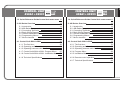
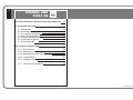

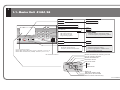
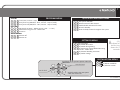

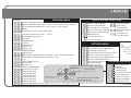
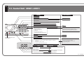
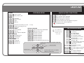
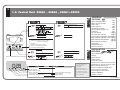

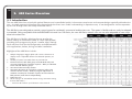
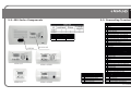

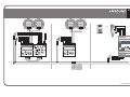
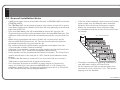

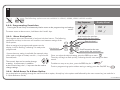
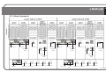

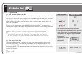
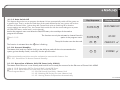
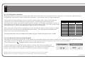
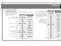
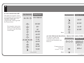
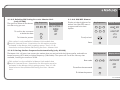
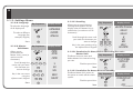
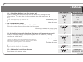
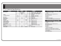
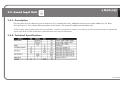


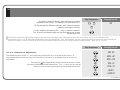
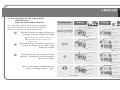
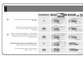
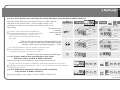

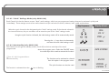
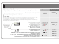

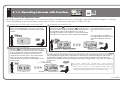
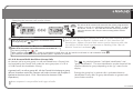
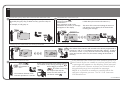
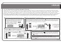
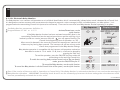
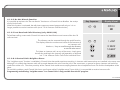

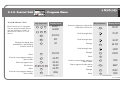

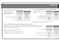

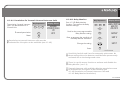
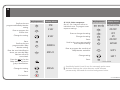
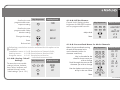
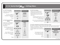
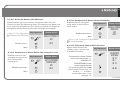
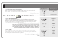

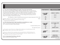
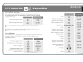
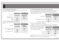
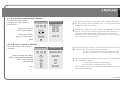


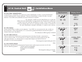
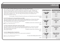
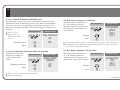
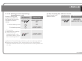
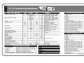
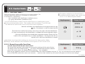
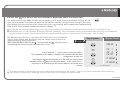
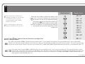
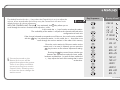
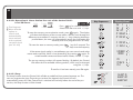


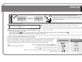

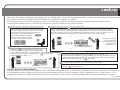
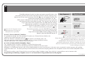


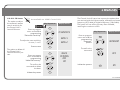
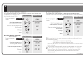
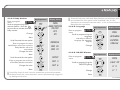
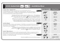
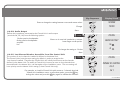
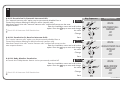
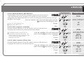

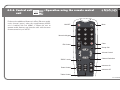
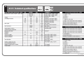

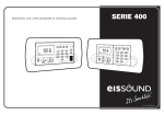
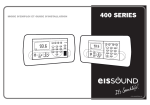
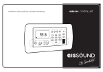


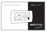
![CC-1140-02 Manual de Uso e Ins[...]](http://vs1.manualzilla.com/store/data/006218676_1-1a958be277725ecc9e1a26233905808d-150x150.png)