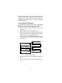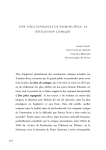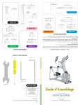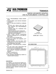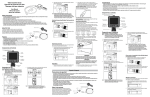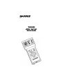
1
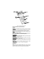
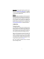
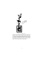
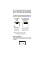
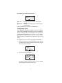
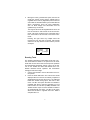
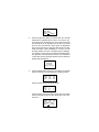
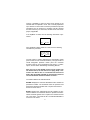
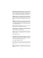
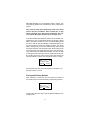
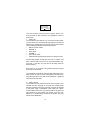
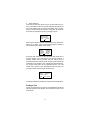
TS®1000
ADSL Test Set
Users Guide
U4p6
n
9
w
: D 04 928
RMeasuxBlt /R:: 7799004% 98%
BCRaaptaec: 10
ts1000_025
No part of this publication may be reproduced, stored on a
retrieval system, or transmitted, in any form or by any means
electronic, mechanical, photocopying, recording, orotherwise
without the prior written permission of HARRIS CORPORATION. The use of trademarks or other designations is for reference purposes only.
NOTICE
HARRIS CORPORATION makes no warranties about this
document. HARRIS CORPORATION reserves the right to
make hardware and software changes to the product
described within this document without prior notice and without obligation to notify any person of such revision or change.
TRADEMARKS
TS®1000 is a trademark of Harris Corporation.
Harris Corporation | 809 Calle Plano | Camarillo, CA 93012-8519 USA
www.harris.com 1-800-437-2266
©1999 Harris Corporation
Printed in USA 0II-727644-001
Issue 2, August 2000
Contents
GENERAL INFORMATION
1
DESCRIPTION
1
Packing List
Physical Characteristics
Keypad Controls and Indicators
OPERATION
1
1
2
3
Testing Procedure
System Configuration
Configuring Tests
Running Tests
Saving and Printing Results
Ending a Test
Viewing Saved Results
Updating Firmware/Software
Inserting/Replacing Batteries
WARRANTY
3
5
6
7
11
13
14
14
15
16
Return of Equipment
i
16
GENERAL INFORMATION
This document provides the user with operating information for
the TS ® 1000 ADSL Test Set manufactured by Harris Corporation, Camarillo, California.
DESCRIPTION
The TS1000 is a portable handheld device designed to be used
primarily by outside plant personnel; however, anyone installing
ADSL will benefit from this easy to use test set. The TS1000 is
powered by four “AA” alkaline batteries.
Packing List
The TS1000 package contains the following:
•
•
•
•
•
TS1000
6 Foot Combination Line Cord (RJ-45 to Telco clips
and RJ-11)
Soft pack carrying case
Four (4) AA Alkaline batteries
TS1000 Users Guide
Ensure that you have identified all of the items that have been
shipped with the unit when unpacking. Inspect the unit for any
damage that may have occurred during shipment. Report any
damage to Harris Corporation Customer Service.
Physical Characteristics
The TS1000 ADSL Test Set is housed in a hand held plastic
injection molded case ideal for field use. The display is a back lit
LCD that features a four line by 16 character resolution. A membrane keypad mounted on the face of the unit features a seven
button keypad. See Figure 1.
1
RJ-45
Interface
Up
w0n4 994268
D
:
RMeasuxBlt /R:: 7799004% 98%
BCRaaptaec: 10
Backlight LCD
Display
Power ON/OFF
Buttons
Backlight
ON/OFF
Button
Arrow
Keys
RS232 DB-9
Interface
ts1000_001
Figure 1. Physical Characteristics
Keypad Controls and Indicators
Keypad
Backlight: The ON/OFF button located on the upper left hand
side of the unit is used to toggle the backlight of the LCD display on or off. The backlight is initially in the OFF position.
Power: The two buttons located on the upper right side of the
unit power the unit on and off.
Note: The TS1000 will automatically power off after two
minutes if no buttons on the unit are pressed.
Arrow Keys
Up Arrow: Returns to the previous option of the main screen
or to the previous results screen.
Down Arrow: Takes the user to the next option on the main
screen or to the next results screen.
Left Arrow: Press to stop a test in progress, exit a test that
has completed or return to the main screen if an error has
occurred.
Right Arrow: Used to execute options from the main
screen such as “Run Test” or “System Configuration”.
Interfaces
RJ-45: The RJ-45 interface located at the top of the unit
accepts the RJ-45 to dual telco clip and RJ-11 cable supplied
with the TS1000. This is the only cable used for testing.
2
RS232 DB-9: Used to update software or firmware. Use a
standard off the shelf NULL modem cable for the procedure. See “Updating Firmware/Software” for additional
information. Do not use the RS232 DB-9 port if the unit
is connected to the ADSL circuit.
Battery
The TS1000 battery compartment is located on the back of
the unit. The alkaline AA batteries can be purchased anywhere batteries are sold. The batteries will allow power for
approximately 300 tests when operated at room temperature. The quantity of tests is based on the realization that
the unit remains on for 2 minutes after the ON button is
pressed and one 15 second test is run. The LCD will display the remaining battery level as a percentage. See
“Inserting/Replacing Batteries” for additional Information.
OPERATION
Testing Procedure
The TS1000 ADSL Test Set can be connected to various
points along the local loop between the Central Office (CO)
and the Customer. The connection points include but are
not limited to the CO, the cross box, pedestal and before or
after the Network Interface Device (NID). This allows the
user to determine the performance throughout the loop.
When connecting to the line, the user must be aware and
cautious of the voltages that will be on the line. The
TS1000 will isolate the user from any harmful voltages
such as ring voltage and station battery once successful
connection to the line is complete. The internal circuitry of
the TS1000 will also be protected from damage as a result
of spikes and DC line power. See Figure 2.
Note: Safe operating procedures must be exercised
when connecting to a line.
3
DC
ADSL
MODEM
ATU-R
TELEPHONE
NID
PEDESTAL
ATUC
ts1000_002
POTS
SWITCH
CROSS
BOX
SPLITTER
DSLAM
CENTRAL OFFICE
Figure 2. Connecting to a Line
Using the RJ-45 to dual telco clip and the RJ-11 Cable, insert
the RJ-45 connector into the TS1000. The telco clips and RJ11 connector can be attached to the line at this time. Connect
the red telco clip to RING and the black telco clip to TIP. Turn
the TS1000 on and ensure the cursor (*) is at the “Run Test”
Option. Press the right arrow key to begin testing.
4
If you are testing after the POTS splitter at the customer premises, you will need to address a different connection configuration. The POTS splitter is used to separate the ADSL
signal from the POTS signal. Before the POTS splitter
(toward the ATU-C), the combined ADSL/POTS signal is carried over pins 4 and 5 for 8 pin connections or pins 3 and 4 for
6 pin connections. After the POTS splitter (toward the ATUR), the ADSL signal is carried over pins 3 and 6 for 8 pin connections or pins 2 and 5 for 6 pin connections. See Figure 3.
RJ-11 Network
Connection
at NID
RJ-11 CPE Connection
in the Customer Premises
after the Splitter
1 2 3 4 5 6
1 2 3 4 5 6
ts1000_003
Pins 3 & 4
contain both POTS
and ADSL signals
Pins 3 & 4 contain POTS
and pins 2 & 5 contain
the ADSL data signal
Note: G. Lite will have both voice and data
terminated on the center two pins.
Figure 3. Diagram of RJ-11 Pin In/Out
System Configuration
Turn the TS1000 on and move the cursor (*) to the “System
Config” option. Press the right arrow key to view TS1000’s
configuration.
Menu Menu B: 90%
View Results
*System Config
Press
to view
ts1000_004
5
The following information will be displayed.
Appl. Ver.
1.30
Modem Ver. 3.6. 70
Press
MainMenu
ts1000_005
Appl. Ver.:
Displays the current software version of the
TS1000.
Modem Ver.: Displays the Alcatel firmware currently running
on the TS1000.
Press the left arrow key to return to the Main Menu.
Configurating Tests
The TS1000 is designed to enable a user to configure
their unit to their specific testing needs and does not restrict the
user to one test type only. The TS1000 can be set to operate as
per international standards T1.413 Issue 2, ITU-T G.992.1
(G.DMT), and G.9992.2 (G.Lite). The user can also specify
maximum limits for negotiation and connection times to the
ATU-C.
To configure the unit to run a test, following the steps below:
1.
Ensure the unit is on. From the Main Menu, scroll down to
the Setup option using the down arrow key. Press the right
arrow key to enter this option.
Main Menu B: 90%
*Setup
View results
Press
to set
ts1000_008
2.
The following screen will appear
Time Limit Setup
*Negotiated
40s
Connected
0s
Press
to change
ts1000_006
To select an option, move the cursor (*) to the desired
option using the up and down arrow keys.
6
3.
Moving the cursor (*) beside each option, the user can
modify the amount of time that the TS1000 tries to
negotiate with an ATU-C (Negotiated) and the amount
of time that the TS1000 remains synchronized with the
ATU-C (Connected). There are some parameters,
such as Noise Margin and Attenuation that are
updated every 10 seconds.
The range of values for the Negotiated time can be set
from 20 seconds to 100 seconds in 20 second increments. The range of values for the Connected time is
from 0 seconds to 100 seconds in 20 second increments.
Pressing the right arrow key multiple times will
increase the time limit until it reaches 100 seconds
and then it will loop back to the first and the process
will repeat.
.
Time Limit Setup
Negotiated
20s
*Connected
20s
Press
to change
ts1000_007
Running Tests
The TS1000 is designed to make ADSL turnup easy. The
unit will emulate an ATU-R to the point that it can handshake and connect with an ATU-C and report the upstream
and downstream parameters. Simply connect to the line,
turn on the TS1000 and select the desired test to run.
Results obtained include upstream and downstream
throughput and noise margin.
1.
Connect the TS1000 to the line. Be aware of the correct pinouts.
2.
Press the Power ON button. The main screen will be
displayed after the unit has successfully completed a
self diagnostic test. Ensure the cursor (*) is positioned
beside the desired testing option; Run Test or Run
G.Lite. The Run Test option will allow the TS1000 to
negotiate with ATU-C’s that are compliant to T1.413
Issue 2 and/or ITU-T G.992.1 (G.DMT) standards. The
TS1000 will also report to which standard it tested to
as negotiated with the ATU-C. The Run G.Lite option
allows the TS1000 to negotiate with ITU-T G.992.2
compliant ATU-C’s.
7
Main Menu B: 90%
*Run Test
Run G.LITE
Press
to start
ts1000_009
3.
Press the right arrow button to start the test. The TS1000
will attempt to negotiate with the ATU-C. If an ATU-C cannot be found, the test will time out. The length of time that
the TS1000 will try to negotiate with the ATU-C is based
upon the time set under the Setup option for Negotiated
Time. Please refer to the Configuring Tests section for additional information. While attempting to connect, the text
message "Modem Connect In Progress" will be displayed.
If connection is made, the test set will automatically display
the upstream and downstream results. If the attempt to
connect fails, the text message "Modem Connect FAILTime
Expired" will be displayed.
Modem Connect
In Progress
9 seconds
Press < to Stop
ts1000_023
4.
If the negotiation with the ATU-C is successful, the TS1000
will be in “showtime” and will display the following results:
Result:
MaxB/R:
B Rate:
Capac:
Dwn
7904
7904
100%
Up
946
928
98%
ts1000_021
Press the down arrow to see more results.
Result:
IntB/R:
NseM :
Power:
Dwn
0
8.0
12.0
Up
0
11.5
7.5
ts1000_022
Press the down arrow to see more results. This new results
screen also allow the user to save the results of the measurement.
Result: Dwn
Up
Atten : 2.0
1.0
Op. Mode: ANSI
Press
to save
ts1000_010
8
There is a possibility to have one more screen appear on the
TS1000 after the Op.Mode: result. This is entirely dependent
upon whether or not the ATU-C has been provisioned to provide
information such as Vendor ID or Provider code. By pressing
the down arrow key one more time, this last screen can be displayed, if applicable.
If the Op.Mode: is ANSI, then the following information is presented.
Vendor ID:
Press
0x22
to save
ts1000_011
If the Op.Mode is either G.DMT or G.LITE, then the following
information is presented.
Prov: Oxf f f f f f f f
Spec. Info: Oxf f f f
ITU rev. #: 0xf f
Press
to save
ts1000_012
The left column of results designates the downstream results
(from the ATU-C to the Customer Premise). The right column of
results designates upstream results (from the Customer
Premise to ATU-C). For an explanation of the “Press -> to Save”
option, see the section titled Saving and Printing Results.
Note: As soon as the TS1000 receives all the results from
the Alcatel ATU-C, the unit will send a "Dying Gasp" command to the ATU-C. This is a command that instructs the
ATU-C that the ATU-R (TS1000) is disconnecting from the
line and the ATU-C should not indicate an alarm.
The results obtained are indicated below:
MaxB/R: Displays the maximum attainable bit rate. Results are
presented in kbits/s. The measured values for upstream and
downstream should be greater than or equal to the minimum
bit rate set in the ATU-C.
B/Rate: Displays the achieved fast bit rate. Results are presented in kbits/s. The measured values for upstream and downstream should be greater than or equal to the minimum bit rate
set in the ATU-C. The result will be 0 if Interleaved Bit Rate is
turned on in the ATU-C.
9
Capac: Displays the capacity of the line. This is the ratio of
achieved bit rate (B/Rate or IntB/R) over the maximum attainable bit rate. Results are presented as a percentage (%).The
value for capacity should be reasonably high (greater than
90%). A low value could mean that there is noise on the line.
IntB/R: Displays the achieved interleaved bit rate. Results are
presented in kbits/s. The measured values for upstream and
downstream should be greater than minimum bit rate set in the
ATU-C. The result will be 0 if Fast Bit Rate is turned on in the
ATU-C.
NseM: Displays the realized noise margin. This is the amount of
increased noise relative to the measured noise power that the
system would be able to tolerate to maintain a bit error rate of
10 -7 . Results are presented in dB. The industry standard is for
a minimum value of 6 dB.
Power: Displays the aggregate power which is a measure of
total output power. Results are presented in dBm.
Atten: Displays the total attenuation. The attenuation is the
measured difference in dB between the power transmitted at
the near end and received at the far end.
Op.Mode: Displays the negotiated Operating Mode between
the ATU-C and the TS1000. Results can be either ANSI,
G.DMT or G.LITE.
If the Op. Mode: is ANSDI:
Vendor ID: Displays the manufacturer information of the ATU-C
called Vendor ID. This result will only appear if the manufacturer’s ATU-C supports this feature. For example, “Vendor ID:
0022” indicates Alcatel Network Systems, Inc.
If the Op.Mode: is GDMT or G.LITE:
Prov: Displays the ITU Provider Code (Vendor ID). This result
will only appear if the manufacturer’s ATU-C supports this feature.
Spec.Info: Displays the ITU Vendor Specific Information. This
result will only appear if the manufacturer’s ATU-C supports this
feature.
10
ITU rev.#: Displays the ITU Standard revision number. This
result will only appear if the manufacturer’s ATU-C supports this
feature.
Care must be taken when interpreting results since many
factors must be considered. These include time of day,
effect of impulse noise, ATU-C setup parameters. See section on Error Messages should an error message occur.
Once the TS1000 received all the results from the Alcatel compatible ATU-C, the unit will release the line by sending a “Dying
Gasp” command to the ATU-C. This is a command that instructs
the ATU-C that the ATU-R (TS1000) is disconnecting from the
line and the ATU-C should not indicate an alarm. The “Dying
Gasp” message may not be sent instantaneously after the last
result was collected. This will depend upon the time limit set for
Connection time under the Setup menu option. See the Configuring Tests section for additional information. The user can stop
a running test if the Connection Time is greater than 0 seconds.
By scrolling through the result screens, rather than seeing the
command “Press > to Save”, the user will see “Press < to stop”.
Result: Dwn
Up
Atten : 2.0
1.0
Op. Mode: ANSI
Press
to stop
ts1000_013
Press the left arrow key once to stop the test. The option now
becomes “Press > to save”.
Saving and Printing Results
After conclusion of a test, the user can scroll to the bottom of
the results screen to access the Saving and Printing functions.
Result: Dwn
Up
Atten : 2.0
1.0
Op. Mode: ANSI
Press
to save
ts1000_010
Pressing the right arrow key on the TS1000 will display the following screen.
11
*Send to PC
Send to Printer
Save in Memory
Press
to send
ts1000_014
The user can then choose from three options: Send to PC,
Send to Printer or Save in Memory. An explanation of each is
given below.
1. Send to PC:
The TS1000 can send data to a PC via a NULL modem cable.
The user must use a PC based terminal program to accept the
data from the TS1000 when this function is per-formed. Please
use the following settings for the terminal program:
• Bits per second: 57600
• Data bits: 8
• Parity: None
• Stop Bits: 1
• Flow Control: None
•
ASCII Receiving: Append line feeds to incoming line ends
The terminal program should allow the user to “capture” text
data. If the text that is sent to the PC from the TS1000 is captured into a *.CSV file, the *CSV file can be easily read into
Microsoft Excel.
Move cursor (*) to the Send to PC position and press the right
arrow key on the TS1000.
The results will include all the upstream and downstream negotiated results as well as Carrier load (bit/bin) information. By
using Microsoft Excel, the data can be plotted for a graphical
look at the test result data.
2. Send to Printer:
The TS1000 can print results to a printer via it’s serial port. The
TS1000 has been designed to work with the portable Seiko
DPU-201 and DUP-414 series of printers. Connect the TS1000
to the printer using a “STRAIGHT” serial cable (not a NULL
modem cable). Move cursor (*) to printer position and press the
right arrow key on the TS1000. The results of the last completed test or recalled Demo results will be printed. The print
transfer rate is 9600 baud.
12
3. Save in Memory
This function saves the results of up to 12 tests. Move the cursor (*) to the Save in Memory position and press the right arrow
key on the TS1000. The user must select which of the 12 positions the results should be saved to, using the up and down
arrow keys to navigate the cursor (*) through memory.
*Send to PC
Send to Printer
Save in Memory
Press
to save
ts1000_015
Each memory location number is followed by three characters,
either “res” or “Emp”. “Res” means reserved (there is already a
file saved there) and “Emp” means empty.
Select
Location#
*#01Res
#03Emp
#02Emp
#04Emp
Press
to save
ts1000_016
Press the right arrow key to save the latest test results into a
memory location. If the user tries to save the test result to a
memory location that is reserved, the user will be given a
prompt asking if the contents of this memory location should be
overwritten. If the answer is “Yes” (pressing the right arrow key),
the original saved data will be replaced with the new test
results. If the answer is “No” (pressing the left arrow key), the
user will be taken back out to the results screen.
Select
Location#
Overwrite Res?
Press
to confirm
ts1000_017
Pressing the left arrow will take the user back to the Main Menu.
Ending a Test
To stop a running test or to exit from a completed test, press the
left arrow button on the TS1000. This will return the user to the
main screen.
13
Viewing Saved Data
The TS1000 is able to save up to 12 results. To recall any of
the saved data, move the cursor (*) to the View Results
option of the Main Menu.
Main Menu B: 90%
Setup
*View Results
Press
to view
ts1000_018
Press the right arrow key to enter.
Select
Result #
Res#01
Res#03
*Res#02
Press
to view
ts1000_019
Using the up and down arrow keys, place the cursor(*) beside
the desired result. Press the right arrow key to view.
.
Result:
MaxB/R:
B Rate:
Capac:
Dwn
Up
9411
969
8000
960
85% 99%
ts1000_020
By scrolling to the bottom of the results screen, the user can
press the right arrow key to print or transfer to a PC the
recalled results.
Press the left arrow key to exit to the Main Menu.
Updating Firmware/Software
Should a bug fix become necessary, updated firmware/software provided by Harris Corporation (www.harris.com). This
firmware/software must be downloaded into a PC before use.
Attach an off-the-shelf NULL modem cable from your PC to
the RS232 DB-9 interface on the bottom of the TS1000. To
upload the firmware/software into the TS1000, press the up
arrow and the Power ON button simultaneously. This will put
the TS1000 into "Monitor Mode" which means the unit is
ready to accept any firmware/software updates.
Run the Harris update software that was downloaded into
your PC. This software will try to connect to the TS1000 via
14
the NULL modem cable. If the connection is successful, a
status bar will indicate the progress of the download. Once
com-pleted, the TS1000 will reset itself and invoke the
updated soft- ware. From this point you may continue testing
or power off the unit.
Inserting/Replacing Batteries
The TS1000 uses standard off-the-shelf "AA" sized alkaline
batteries. It is recommended you replace the batteries once
the Battery Indicator on the LCD display shows 10%.
1.
Ensure the unit is disconnected from the line and is
turned OFF.
2.
Remove battery cover by removing the screw.
3.
Remove old batteries from TS1000 and discard/recycle.
Be sure to follow local and national laws in the proper
disposal and/or recycling of alkaline batteries.
4.
Insert 4 new "AA" sized alkaline batteries. Be sure to
properly align battery terminals and the TS1000 battery
con-nections.
ts1000_024
Figure 4. Battery Placement
5.
Place the battery cover over the batteries and tighten the
screw.
6.
Turn on the TS1000 to make sure the unit operates properly.
15
WARRANTY
Harris warrants that the TS1000 Test Set shall be free of any
defects in parts or workmanship, for a period of 18 months and
the line cord for a period of 12 months from the date of manufacture, if used under Harris operating specifications.
THIS IS THE ONLY WARRANTY MADE BY HARRIS CORPORATION AND IS MADE EXPRESSLY IN LIEU OF ALL OTHER
WARRANTIES EXPRESSED OR IMPLIED, INCLUDING BUT
NOT LIMITED TO ANY IMPLIED WARRANTIES OF MERCHANTABILITY OR FITNESS FOR ANY PARTICULAR PURPOSE. Should any parts or workmanship prove defective,
Harris will repair with “not used” or reconditioned parts, or
replace the Product, at Harris’ option, at no cost to the Buyer
except for shipping costs from the Buyer’s location to Harris’
location. This is the Buyer’s SOLE AND EXCLUSIVE REMEDY
under the agreement.
All incidental or consequential damages shall be excluded.
This warranty does not extend to products which have been
subjected to neglect, accident or improper use, nor to units
which have been altered or repaired by other than authorized
Harris personnel.
Return of Equipment
To return the test set to Harris, first obtain a Return Authoriza
tion (RA) Number from our Customer Service. This return
authorization number must be clearly marked on the shipping
label, or the container will not be accepted by Harris. See the
sample label below:
To:
HARRIS CORPORATION
809 Calle Plano
Camarillo, California, USA 93012-8516
Attention: Customer Support, RA #XXXXXX
16
Note: Do not use RS232 port when unit is connected to the ADSL line.
Harris Corporation | 809 Calle Plano | Camarillo, CA 93012-8519 USA
www.harris.com 1-800-437-2266
©1999 Harris Corporation
Printed in USA 0II-727644-001
Issue 2, August 2000