1
1
Mitsubishi Electric Air Conditioning Network System
Integrated centralized control software TG-2000A
Operation Manual (Management)
Contents
1. Safety Precautions............................................................... 1
2. Introduction .......................................................................... 3
2.1 System Requirements ................................................ 3
2.2 Preoperation Check List.............................................. 4
2.3 Items to Check before Starting Operation ................... 5
3. Names and Functions of Each Part ..................................... 6
3.1 Screen Configuration .................................................. 6
3.2 Operations .................................................................. 7
3.3 Functions Table .......................................................... 7
4. Screen Basic Operation ....................................................... 9
4.1 Function Select Buttons and Display Units Buttons .... 9
4.2 Display Units Buttons Operation ............................... 10
4.3 Display method for Site change display .................... 12
4.4 Display method for Mail display ................................ 12
4.5 Startup and Shutdown .................................................. 13
5. Initialization Before Use ..................................................... 14
5.1 Schedule Setting....................................................... 14
5.2 Air-conditioning Charge Setting ................................ 14
5.2.1 Charge Setting .................................................. 14
6. Normal Operation .............................................................. 20
6.1 Monitor/Operation ..................................................... 20
6.2 On/Off Operation ...................................................... 20
6.3 Operation Status Monitor .......................................... 21
6.4 Operation Details ...................................................... 26
6.5 Other Functions ........................................................ 30
7. Schedule Setting................................................................ 32
7.1 Today’s Schedule Setting ......................................... 34
7.2 Weekly Schedule Setting .......................................... 38
7.3 Annual Schedule Setting........................................... 44
7.4 Schedule View .......................................................... 49
7.5 Schedule Copy ......................................................... 51
7.6 Enabling/Disabling the Schedule Settings ................ 51
8. Maintenance Operation ..................................................... 52
8.1 Abnormality History and Operation History ............... 52
8.2 Error Code List.......................................................... 57
8.3 Filter Reset (Check water circuit reset) Operation .... 62
8.3.1 Automatic Status Display .................................. 62
8.3.2 Manual Status Display ...................................... 63
8.4 Operation Time Display ............................................ 64
8.5 Abnormality Occurrence ........................................... 65
8.5.1 Abnormality Display .......................................... 65
8.5.2 Abnormality Reset Operation ............................ 67
8.6
8.7
8.8
8.9
8.5.3 PLC and Meter Troubleshooting........................ 67
8.5.4 Warning Message Screen Display .................... 68
Meter Status Monitor ................................................. 77
Trend Data Output .................................................... 78
Peak Cut Status History Data Output ........................ 81
Checking of the gas amount ..................................... 83
9. Air-Conditioning Energy Monitor ........................................ 85
9.1 Charge Display Function ........................................... 85
9.2 Block and Meter Air-conditioning Energy Monitor
Display ...................................................................... 89
9.3 Air-conditioning Charge Output ................................. 90
9.4 Air-conditioning Charge Basic Setting ....................... 94
9.5 Under Stop Charge ................................................. 103
9.6 Recalculate the Air-conditioning Charge ................. 104
9.7 Last month calculation (Only when "connect when
needed" is selected.) .............................................. 104
10. Trend Graph....................................................................... 105
10.1 Graph Display............................................................ 105
11. System Display (View screen) ......................................... 108
11.1 System Configuration Display ................................. 108
11.2 Displaying the DIDO, AI and PI controller Setting ........ 111
11.3 PLC for General Equipment Setting Display ........... 113
11.4 Displaying the IC I/O Signal Settings ...................... 115
11.5 Display of Monitor Display Setting .......................... 116
11.6 Watt Hour Meter/Meter Setting Display ................... 117
11.7 Charge System Display........................................... 119
11.8 Energy Saving Setting Display ................................ 122
11.9 Night Mode Set-up Display ..................................... 124
11.10 System-changeover Set-up Display ....................... 124
11.11 Others Set-up Display ............................................ 125
12. Help ................................................................................. 126
12.1 Contents.................................................................. 126
12.2 Version Information ................................................. 126
13. System Operation Precautions ........................................ 127
13.1 Usage Right ............................................................ 127
13.2 Operation and Setting Precautions ......................... 127
13.3 Air-conditioning Charge Precautions ....................... 128
13.4 Others ..................................................................... 130
14. Maintenance and Service ................................................ 131
Appendix 1: Using Charge Calculation Tool ........................... 132
Appendix 2: Using Trend Graph Display Support Tool ......... 136
Before using the TG-2000A, please read this manual carefully to ensure proper operation.
Retain the manual for future reference.
WT03902X28
(Ver.6.5*)
In this manual, Microsoft® Windows® 8.1 Pro is called Windows 8.1, Microsoft® Windows® 7 Professional
is Called Windows 7, and Microsoft® Windows Vista® Business is Called Windows Vista.
In this manual, Microsoft® Excel 2013/2010/2007 is called Excel.
Trademarks
MS, Microsoft, Microsoft logo, and Windows are registered trademarks and trade names of Microsoft
Corporation. Adobe® Reader® is the trademark of the Adobe systems Incorporated.
Each company may use as registered trademarks and trade names the product names used in this
manual.
-About this manualThe operation manual consists of three volumes, “Site adjustment”, “Management” and “Wide area”.
This manual is “Management”.
Site adjustment:
Contain initial setting procedures for TG-2000A (e.g., setup and system setting) and how to
correct charging data and remedy.
Management (this manual):
Contain normal operation procedures for TG-2000A (e.g., Monitor/Operation function of air
conditioners).
Wide area:
Contain setting/operation procedures of “Site change tool” and “Mail tool” for using TG-2000A in
the wide area mode.
Refer to the manual “Management” for Monitor/Operation function of air conditioners.
These manuals are accessible from the Help menu on TG-2000A.
Adobe® Reader® is required to read these manuals. (Version 10 or later recommended)
-- Term description -
"Man-machine"
: Indicates a computer with integrated centralized control software TG-2000A.
(Man-machine interface abbreviation)
"Centralized controller" ("AE-200E," "AE-200A," "AE-50E," "AE-50A," "EB-50GU-J," "EB-50GU-A,"
"AG-150A," "AG-150A-A," "GB-50ADA-A," "GB-50ADA-J," "G-50A" or "GB-50A"):
In this manual, "AE-200E" and "AE-200A" are referred to as "AE-200,"
"AE-50E" and "AE-50A" are referred to as "AE-50," "EB-50GU-J" and
"EB-50GU-A" are referred to as "EB-50," "AG-150A" and "AG-150A-A"
are referred to as "AG-150A," "GB-50ADA-A" and "GB-50ADA-J" are
referred to as "GB-50ADA."
The "AE-200" monitors and operates with the "AE-50" as a subordinate
unit, but with the TG-2000A software, the "AE-200" and "AE-50" are each
connected for monitoring and operation.
With the "AG-150A", if the Expansion controller (PAC-YG50ECA) is
connected, it is connected to the "AG-150A" for monitoring and operation.
TG-2000A Ver.5.50 or later supports AG-150A connection.
TG-2000A Ver.6.30 or later supports GB-50ADA-A and GB-50ADA-J connection.
TG-2000A Ver.6.34A or later supports AG-150A-A connection.
TG-2000A Ver.6.40A or later supports EB-50 connection.
TG-2000A Ver.6.50 or later supports AE-200 and AE-50 connection.
"Expansion controller" (EC)
"PLC"
: A controller (PAC-YG50ECA) that is used when the number of units that
AG-150A controls, such as indoor units, LOSSNAY and general equipments,
exceeds 50.
Each AG-150A unit can control up to a total of 150 units (when used with
three expansion controllers).
: Abbreviation for Programmable Logic Controller.
The TG-2000A system uses two PLCs; the electric amount count software
and PLC for general equipment software.
The electric amount count software measures the electric amount with the
PLC, the general control operates and monitors the general equipment, etc.
"Charge function” (Power apportioning):
Charge function that apportions the electric amount used by the air
conditioner.
The following three methods are available:
Manual electric amount input
A watt hour meter (WHM) is not connected, and instead the charge
percentage is calculated according to the percentage of power used.
The service power is measured with the separately installed WHM, and
the service charges are obtained from the charge percentage.
Electric amount pulse count
The electric amount is measured either by the PLC or PI controller, and
the service electric amount is monitored by via the LAN to automatically
apportion and calculate the electricity charges.
To measure by the PLC, use the designated PLC and optional
software.
Direct read in of power value into computer
The RS-485 output watt hour meter is directly connected to the computer
containing the integrated centralized control software (via an
RS-232-C/RS-485 converter), and the service power is input.
The service power rate is automatically apportioned and calculated.
"WHM"
: Abbreviation for Watt Hour Meter.
"Service power rate"
: The service power rate indicates the power rate (apportioned rate)
apportioned based on the service state of the air conditioner, etc.
"Always connected to AG-150A/G-50A system - Activate": <recommended mode>
Refers to charging method that is operated by connecting this integrated
centralized control software TG-2000A constantly to the centralized
controllers and PLC via a LAN. Leave the computer power ON to keep the
TG-2000A running.
PI controller instead of the PLC can be connected.
"Always connected to AG-150A/G-50A system - Deactivate":
Refers to charging method that connects this integrated centralized control
software to the centralized controllers and PLC once a month via the LAN.
The charges for the last month are calculated and output at once. The
charge function can be used efficiently by starting the computer and
integrated centralized control software TG-2000A on the day after the set
settlement date.
PI controller instead of the PLC can be connected.
"IC I/O signal"
: Refers to a contact mounted on the air conditioner's indoor unit. A general
equipment can be connected to the IC I/O signal using this contact and a
PLC for general equipment to operate and monitor the system.
"DIDO controller" (DC)
: Refers to the controller (PAC-YG66DCA) that can monitor or control
general equipment.
"AI controller" (MCT)
: Refers to the controller (PAC-YG63MCA) that has a function to measure
temperature and humidity.
"PI controller" (MCP)
: Refers to the controller (PAC-YG60MCA) that has a function to calculate
cumulative pulses from such metering devices as watt-hour meter.
"Air To Water (PWFY)"
: Refers to Air To Water Booster Unit (BU) and Air To Water HEX Unit (AU)
that can be connected to AE-200/AE-50/EB-50/AG-150A/GB-50ADA.
G-50A cannot be connected.
"HYBRID CITY MULTI"
: Refers to Hydro BC controller (HBC) that can be connected to AG-150A
Ver.2.80 or later and AE-200/AE-50. G-50A cannot be connected.
"HWHP (CAHV)”
: Refers to HWHP main (CEH) and HWHP sub (CL) that can be connected
to AG-150A/GB-50ADA Ver.2.90 or later and AE-200/AE-50. EB-50 and
G-50A cannot be connected.
"Advanced HVAC CONTROLLER”: Refers to Advanced HVAC CONTROLLER (AHC) that can be
connected to AE-200/AE-50/EB-50. AG-150A/GB-50ADA/G-50A
cannot be connected.
- About screen This instruction manual may use the development version screen in some case.
- Simple operation manual The simple operation manual is stored as a pdf file in the "Manual" folder on the TG-2000A Setup CD.
Adobe® Reader® (Version 10 or higher recommended) is required to view this pdf file.
COPYRIGHT (C) 2002 (2014) MITSUBISHI ELECTRIC CORPORATION ALL RIGHTS RESERVED
1. Safety Precautions
• Please read the Safety Precautions section very carefully before using the unit.
• The safety cautions provided here are very important for your safety. Please observe them at all times.
• The degree of danger involved with incorrect operation of the unit are indicated in this manual using the
following symbols.
WARNING
CAUTION
•
Incorrect operation could result in death or severe injury.
Incorrect operation could result in injury or damage to property.
After reading this information, please keep this manual together with the operation manual (site
adjustment manual) in a location where the operator can see it. Also, when changing operators give
both of these manuals to the new operator.
Note:
• Please observe the safety precautions detailed in the installation manuals and operation
manuals of the other machines such as computers, peripherals, and air conditioners.
WARNING
The customer must not do any wiring or
electrical work.
Have the dealer or a specialist do any wiring or
electrical work. Do not do it yourself. Doing the
work yourself may result in improper installation
which may cause electric shock or fire.
Do not relocate the unit yourself.
Relocating the unit yourself may result in
incorrect installation which may cause electric
shock or fire.
To relocate the unit, consult the company from
which the unit was purchased.
Do not make any improvements or repairs
for any reason.
Making improper improvements or repairs may
cause electric shock or fire. For repairs, consult
the company from which the unit was
purchased.
Read the installation manuals and operation
manuals for the computer, peripherals and
other machines.
Improper operation could result in fire or
damage to the computer or peripherals.
Stop operation immediately if an error
message appears on the computer and the
unit stops or is not operating properly.
Failing to do so may result in fire or damage to
the unit.
Immediately contact the company from which
the unit was purchased.
Read the installation manual and operation
manual for the air conditioner controller.
Improper operation could result in fire or
damage to the air conditioner controller.
CAUTION
Do not use the product for any other
purpose.
This product is for use with the Mitsubishi
Electric Building Air Conditioning Control
System. Do not use it with any other air
conditioning control system or for any other
application. Doing so may cause the unit to
malfunction.
Keep children away from the unit.
Inspections and maintenance can be dangerous. Do not let children near the unit during
these times.
Do not use with other applications.
Use the computer that uses this product
with this product only.
Using it with other applications may cause
faulty operation.
Warning to all users (User Agreement)
This document is a contract between the customer and Mitsubishi Electric Corporation. By using this
application, you agree to the following conditions and are considered a user.
• Mitsubishi Electric and associated suppliers are not responsible for any collateral, secondary,
or special damages, even if notified by the distributor of the possibility of a certain type of
damage. Mitsubishi Electric is not responsible for any rights claimed by a third-party.
1
Safety Guidelines for the Computer Running with the TG-2000A.
(1) Precautions for selecting a computer
Select a desktop computer.
• Depending on the function, it is recommended to use a
desktop as opposed to a laptop computer as there is
a tendency for heat to build up in a laptop.
• Some laptop computers cannot be run for long
hours.
Computer based UPS recommended.
• It is recommended to use a UPS to protect data from
momentary power outages or power cuts.
It is particularly recommended to employ a UPS when
using charge function (power apportioning).
Use a computer/operating environment with specifications capable of running the TG-2000A function.
• Run the function using the specified OS. There is a possibility that the function cannot be used when running an
OS other than specified.
• Use a business model computer. There are cases when it is not possible to install or run the application with
other applications on a computer or laptop intended for personal use.
(2) Precautions for General usage
Do not place the computer in any of the following Ensure to read the computer / peripheral
instruction manual.
locations.
• An error or accident may occur when using in the • A fire or accident may occur due to improper use of the
equipment.
following environments.
Avoid covering the computer or AC adapter with
a cloth or blanket, or locating them on or near a
heater.
• There is a possibility of internal temperature build-up,
fire or burning under the above situations.
A place where there is: a lot of dust, a likelihood of
shock or vibration, instability, a heater or speaker
nearby, direct exposure to sunlight, a likelihood of
dropping, a possibility that the computer may be
exposed to moisture or high temperature, or where it
may be exposed to sudden temperature fluctuations or
heat.
Cut the power or disconnect the power cable
immediately if smoke, or an abnormal smell or
noise emanates from the computer.
Do not close the lid when using a laptop.
• Using the computer in the above circumstances may
• There is a possibility of an internal temperature
result in fire, burning, or electric shock. Please consult
build-up, fire or burning. Use in an area with sufficient
the maker of the equipment/computer.
ventilation.
• The system may start Stand By or Hibernate function Use the hard disk, floppy disk, or CD media as
and stop functions of TG-2000A by closing the lid.
indicated.
• Do not expose the hard disk, floppy disk, or CD to
Do not touch the computer air vent.
shock or vibration during use.
• The air emitted by the ventilator is hot and may result in
• Do not cut the power or reboot the computer while the
burning if exposed to the skin.
hard disk, floppy disk, or CD is in use.
•
Always turn OFF the power when moving the computer.
Do not tamper with the computer fan.
• Tampering with the computer fan may result in a
temperature build-up, fire, or accident.
Reboot the PC periodically.
• The Windows operating system has an inherent
potential for developing problems after running
continuously for a while.
(3) Other precautions
Precautions relating to the computer and peripheral equipment
• Please consult the maker regarding damage to the computer or peripheral equipment.
responsible for damage occurring at the user’s site.
We will not be held
Protecting the computer from virus attacks
• Take appropriate measures to avoid computer virus infections when saving or copying data via network connection
or external media such as USB memory. Mitsubishi Electric shall not be held responsible for any damages that
may result from computer virus infections.
Safety Guideline for LAN connection of the centralized controller
Connect the centralized controller to a private network.
• The centralized controller is designed to be used with TG-2000A on a private network.
• Use a security device such as a VPN (Virtual Private Network) router when connecting to the Internet.
2
2. Introduction
This integrated centralized control software TG-2000A is used to monitor/operate an air conditioner
group with multiple centralized controllers connected.
The instruction manual for this integrated centralized control software TG-2000A consists of Site
adjustment, Management (this manual), and Wide area.
Before using the integrated centralized control software TG-2000A, thoroughly read the following
precautions. Also read Chapter 13 “System Operation Precautions”.
2.1
System Requirements
We recommend the following software and hardware when using this application (TG-2000A).
Item
PC
CPU
Memory
OS
Requirement
PC/AT compatible machine
Operation confirmed using HP and Dell
Recommended
(Business model is recommended)
computers
CoreTM 2 Duo 1.66GHz or faster
In the case of Windows® 8.1 / 7 (64bit) : 2GB or more
In the case of Windows® 7 / Vista® (32bit) : 1GB or more
Windows® 8.1 Pro (64bit)
CoreTM i3 1.6GHz or faster
4GB or more
2GB or more
English version only
Only compatible with “Pro” and “64 bit”
versions of Windows® 8.1
Not compatible with Windows® 8
HDD
Windows® 7 Professional (64/32bit)
Service Pack 1 (*1)
Windows Vista® Business (32bit)
Service Pack 2 (*1)
Standard
6GB or more (2GB or more of C drive
free space necessary)
English version only
English version only
40GB or more of C drive free space necessary
when using the trend function. The drive used
for automatic output must have the following
free space according to the number of groups.
200 groups = 2GB, 500 groups = 5GB,
1000 groups = 10GB, 2000 groups = 20GB
Wide area
20GB or more (Free space)
CD-ROM drive / DVD-ROM drive (*2)
Storage
device
Resolution
Serial port
1024 × 768 or higher, 65536 colors or more
1 port or more
LAN
Modem
1 port (100BASE-TX /10BASE-T)
56K modem or TA
USB
Other
2 port or more
Computer must be dedicated for this use (TG-2000A).
Standard : max. 200MB/site
Devices other than those shown at the left may
also be installed.
Required when using RS-485 communication
WHM (Not necessary when using PLC)
(*3)
Required when using a modem in wide area
mode.
For the data backup.
Must be used for 24-hour constant
operation (*4)
*1: It is necessary to correspond to each Service Pack. TG-2000A is not normally set up at the uncorrespondence.
Please apply Service Pack of the correspondence.
*2: To set up “.NET Framework 3.5” using the Windows® 8.1 setup disk (DVD), a DVD-ROM drive is required.
*3: Purchase the option, or use the equipment recommended for the computer when purchasing the computer.
*4: Reboot the computer where TG-2000A is installed, once a week.
3
2.2
Preoperation Check List
(1)
Installation conditions check
Check the wiring, connection, initial settings etc of the computer and peripheral devices.
Verify that each device is installed in accordance with its installation and instruction manuals.
(2)
Site adjustment check
Before using the system, make sure that the initialization and test running described in the
Operation Manual (Site adjustment) are complete. Back up the system information database
after initialization and test run were performed.
(3)
Printer check
When this system is used with a printer, leave the printer power on and check that there is paper
in the printer.
(4)
PLC check
To use the charge function (electric amount pulse count) or general equipment, turn the PLC
power ON and stay in the RUN state. Make sure that each software is installed in the PLC and
that initialization has been executed from the integrated centralized control software TG-2000A.
(5)
Optional functions of the centralized controller
The optional functions of the centralized controller will include “Annual/weekly schedule”,
“Charge calculation”, etc. The license number must be registered in each centralized controller
to use the optional functions with this integrated centralized control software TG-2000A.
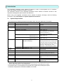
Optional function
Monitor/operation function
Schedule function
Energy monitoring function
Energy saving function
Peak cut function
Personal browser function
PLC for general equipment
function
AE-200/AE-50/EB-50
/AG-150A/GB-50ADA
Basic License Pack
or Web Monitor
Basic License Pack
or Annual Schedule, Weekly
Schedule
Energy Management License
Pack *1
Energy Management License
Pack
Energy Management License
Pack
Personal Web
PLC for General Equipment
G-50A
Web Monitor
Annual Schedule, Weekly
Schedule
Charge *1
Saving Energy control
Saving Energy control (peak cut)
Personal Web
PLC for General Equipment
*1 The Charge license registration is also required when the trend data for peak cut electric
power (block) is set to be output.
Make sure that the license No. corresponding to the function to use is registered in the centralized
controller.
Note:
Refer only to the functions that have been purchased.
Only option functions for which the license has been registered will work.
By using this TG-2000A, the user agrees to the conditions of the License.
4
2.3
Items to Check before Starting Operation
(1)
About the Windows (Reboot function)
Be sure to set the Reboot settings.
Reboot the PC periodically both manually and automatically.
Refer to Section 8.3.2 Reliability Function in the Operation manual (Site adjustment) for how to set the
Reboot settings.
Periodically (approx. once a week), shut down the TG-2000A and manually reboot the Windows.
Shut down the TG-2000A before rebooting the Windows.
The Windows operating system has an inherent potential for developing problems after running
continuously for a while.
Perform manual reboot between 08:00 and 21:45.
After the Windows was manually or automatically rebooted, check that the TG-2000A is operating
properly.
Set the automatic login settings for the PC.
If the automatic login settings are not set, the TG-2000A will not automatically restart after the PC is
rebooted.
(Refer to Section 5.1.2 Preparing for TG-2000A setup in the Operation manual (Site adjustment) for
details.)
The system manager is asked to ensure that the system operators are aware of the need to set the
Reboot settings and to manually reboot the Windows periodically.
Failing to reboot the Windows may cause certain functions of the TG-2000A (e.g., billing function and
“Trend” function) to malfunction.
(2)
Data backup
It is recommended to back up the operation data to safeguard against accidental data loss.
Refer to Appendix 5: Backing Up the System Setting Data in the Operation manual (Site adjustment) for
the data backup procedures.
(3)
Power supply processing
When "Always connected to AG-150A/G50A system" is set to “Activate” (recommended setting)
or the “Trend” function is used
After installation and adjustment, do not turn off the power to the system devices and air
conditioner including TG-2000A, except when a failure occurs, or when servicing the
equipment.
(Periodically reboot the TG-2000A according to the procedures outlined in section (1) About the
Windows (Reboot function), even when the above functions are used.
If the system devices or air conditioner power is turned off, a failure may be displayed. When
the power is turned back on, the display will automatically return to normal.
In all other cases
After installation and adjustment, do not turn off the power to the system devices and air-conditioner,
other than the TG-2000A, except when a failure occurs, or when servicing the equipment.
If the system devices or air conditioner power is turned off, a failure may be displayed. When
the power is turned back on, the display will automatically return to normal.
(4)
Screen processing
The computer of TG-2000A, please do not use the screen saver.
The screen saver is not displayed while TG-2000A is active.
5
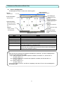
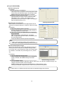
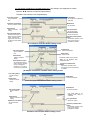
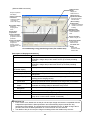
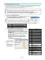
3. Names and Functions of Each Part
3.1
Screen Configuration
The Management screen consists of the following parts:
Display units buttons
Menu bar
Select the menu.
Select the Display unit screen.
Floor switching box
Function select buttons
Select the function.
Select the Floor screen.
Sub screen
Display the sub screen
configured of several floors.
The floor appears when
clicked on.
System status display
Display the state (normal/
Group icons
error) other than the group
icon.
Display the air-conditioner or
etc. group.
A menu appears when clicked.
Status bar
Display a message
Batch button
or the date and time.
Select for batch operation
Management screen
Item
Group icon
Function select buttons
Display units buttons
Floor switching box
Status bar
System status display
Sub screen
of the floor, block and whole
building.
Details
Display the state of the air conditioner or etc., and operates On/Off.
Select the function.
Select the display unit for each function.
Switch the floor.
Display the operation procedure message and current date/time.
Display the status (normal, abnormal) of the centralized controller, watt
hour meter (WHM), PLC, and other units.
Display the sub floor configured of several floors.
The sub floor can be selected with the scroll bar. When a section to be displayed is
clicked, that floor will appear. (Option)
Note
When AG-150A is connected to the expansion controllers (EC), "(G-50 No.) - (EC No.)" is displayed in the
"G-50 No. (or AG-150A/G-50A No.)" field.
e.g. 1: When AG-150A is connected to expansion controllers, AG-150A No. is 1, and EC No. is 1,
"G-50 No." will be "1-1".
e.g. 2: When AG-150A has no connection with expansion controllers, and AG-150A No. is 2,
"G-50 No." will be "2".
e.g. 3: When G-50A No. is 3,
"G-50 No." will be "3".
Some screens display "G-50 No." and "EC No." separately. In this case, "EC No." will not be displayed in
the "G-50 No." field.
6
3.2
Operations
Mouse operation
The following description assumes that a mouse is used as the pointing device. When using another
pointing device, read the description for that device.
Operation on the screen is the same.
The keyboard can also be used to input characters and numbers.
Move the mouse while viewing the arrow (mouse pointer) on the screen.
Use the left mouse button only.
The following describes the operations:
Item
Click
Double click
Drag
Keyboard
3.3
Details
Pressing and releasing the mouse button once is called “click”.
This operation is used when selecting a button.
Pressing and releasing the mouse button twice in rapid succession is
called “double click”.
The mouse pointer is moved to an icon and the left mouse button is held
down. When the mouse is moved in this state, the icon moves as if it were
being dragged. This operation is called “drag”. The icon can be left at the
new position by releasing the left mouse button.
Primarily used when entering password, characters, or numbers.
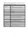
Functions Table
The integrated centralized control software TG-2000A has two major functions.
1) Function which monitors the operation status of the air conditioner and controls and sets the
air conditioner.
2) Operation function and system initialization and maintenance function.
This section mainly describes function 1).
Function 1) consists of the items shown below. The screen that displays this function is called the
“Management screen”.
Name
Air conditioner on/off
General equipment
On/Off (Option)
Air conditioner control
Prohibition of local
remote controller
operation
History
Cumulative time
(Option)
Schedule setting
(Option)
Air-conditioning charge
monitor (Option)
Trend data output
(Option)
Function
On/off operation can be performed in group, floor, block, or
whole air conditioner units. The operating status can also be
monitored.
The general equipment can be turned On and Off, and the
operation state can be monitored.
Operation (heat/fan/cool/dry) can be switched and the room
temperature can be adjusted in group, floor, block, or whole air
conditioner units.
Operation can be permitted and prohibited from the local
remote controller in group, floor, block, or whole air conditioner
units.
The history of abnormalities and operation can be referenced in
group, floor, block, or whole air conditioner units.
The air conditioner cumulative operation time can be
referenced for each group.
Air conditioner operation can be scheduled for each group.
Reference
6.1, 6.2
6.1, 6.2
6.4
6.4
8.1
8.4
7
The air-conditioning charge or ratio result for each block and
watt hour meter can be displayed.
9
The trend data, such as the set temperature, intake
temperature, meter and peak cut status history, can be output.
8.7, 8.8
* Some functions may unusable.
7
The following items are necessary when the system configuration was changed, but are not covered in this
manual.
Change operation requires knowledge of system set-up. For the detailed contents and operating
instructions, refer to the separate “Site Adjustment manual”.
Name
User set-up
Centralized controller
connection set-up
System configuration set-up
DIDO, AI and PI controller
set-up
PLC for General equipment
set-up
IC I/O signal set-up
Monitoring screen set-up
Watt Hour Meter set-up/
Measurement Meter set-up
Energy monitoring set-up
Charge set-up
Energy saving/peak cut
set-up
Night mode set-up
System-changeover set-up
Others set-up
Time set-up
Maintenance of charge data
Operation amount(/electric
amount) data monitor
Remedial apportioning
setting
Maintenance of comparison
data for energy monitoring
Test run for energy
monitoring
Function
Set the validity of the TG-2000A functions.
Register the number of centralized controller and Expansion
Controller (EC).
Register the IP address set to the centralized controller.
Perform connected devices, refrigerant system connection, group,
operation mode and other functions settings and block and other
settings.
Set the name, function, and measurement range and pulse value for each
equipments, etc.
Set the IP address of PLC for general equipment and the general
device's functions, etc.
Set the general equipment connected to the IC I/O signal, etc.
Set the type of unit, number of floors, plan view, layout of group icon,
operation block, etc.
Set the number of meters (WHM) and unit, etc.
Perform various settings for air-conditioning charge calculation.
Set the charge unit, time zone, basic charges, and seasonal period,
etc.
The centralized controller for energy saving operation, the control
state of the indoor units in each operation block, and the control
status of each outdoor unit is set for energy saving.
The object and time which reduce outdoor unit operation sound are
set up.
Change mode is set up for the mode for every mode change block.
Set External temperature interlock control and Night setback control.
(only AE-200/AE-50/EB-50/AG-150A/GB-50ADA)
Set the current time.
(NOTE) This function should be used for TG-2000A.
Past charge data can be referenced.
Monitor operation/electric amount data backed-up at the centralized
controller.
Remedy charge apportioning at WHM failure, etc.
Clear the apportioning comparison data when the centralized
controller or PLC is replaced due to a fault, etc.
Trial operation of the charging system can be completed easily in
one day.
8
4. Screen Basic Operation
The function is selected with the function select buttons (top left-hand side of screen) and the operation
object is displayed on the display & operation screen with the display units buttons (top right of screen).
4.1
Function Select Buttons and Display Units Buttons
This table shows which function display buttons and Display units buttons should be selected when
performing an operation.
Display units
buttons
Function select
Select the system
buttons
Select the monitor /
equipment, whole
operation, history,
building, block and
operation time, filter
floor display unit
sign, and air-conditioner
Sub screen
Display the whole floor
configured of several floors.
The floor appears when
clicked on.
charge function
Display & operation screen
Control screen
The V symbol indicates that the operation can be performed and the – symbol indicates that the
operation cannot be performed.
Operation
Display units buttons (display object)
System
Floor
Whole
Block
equipment
building
Group Floor
*1
Monitor/Operation
–
V
V
V
V
Monitor/Operation
V *2
V
V
V
V
Function select
button
On/off (Run/stop) switching
Operation status
(run/stop/abnormality) check
Detailed setting of operation mode,
Monitor/Operation
temperature, etc.
Operation prohibition setting from local Monitor/Operation
remote controller
Annual schedule, weekly schedule
Monitor/Operation
and today’s schedule setting (Option)
Temperature/humidity display
Monitor/Operation
Abnormality history and operation
History
history check (Option)
Cumulative time check (Option)
Cumulative time
Filter sign reset
Filter reset
Energy monitoring (Option)
Energy monitoring
V
V
V
V
–
V
V
V
V
–
V
V
V
V
–
–
–
–
V
–
V
V
V
V
V
–
–
–
–
–
V
V
V
–
–
V
–
–
–
–
*1: System equipment includes Centralized controller, Expansion controller (EC), the units other than
the indoor units and general equipment.
*2: Normal/abnormal display only.
9
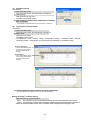
4.2
Display Units Buttons Operation
The methods of operating the air-conditioners in group units, block units and for the whole building,
and the methods of operating the general equipment in group units and in batch units are explained in
this section.
(1)
Floor screen
On the floor screen, the air-conditioner (general equipment) can be turned on/off, the operation
and schedule can be set and monitored, and the floor can be switched.
Floor switching box
Use the “/” buttons or
combo box to select the floor
to be displayed.
Sub screen
Display the whole floor
configured of several floors.
The floor appears when
clicked on.
Floor batch button
Click this to operate the
floors in a batch.
Icon selection menu
The selection menu appears
when the icon is clicked.
Click the item to be selected.
Floor screen
When controlling the air-conditioners and general equipment and the [Floor
batch] button is clicked, the Air-conditioner operation and General
equipment operation selection screen opens.
Select the target to be operated, and then select the items to be operated.
Either the Sub screen for several floors or the screen for a floor can be displayed on the Sub screen.
(The Sub screen can be displayed by selected "split floor" in the user settings.)
Display position change
The position where the whole floor
is displayed can be moved by
dragging.
Floor selection
Using the cursor, select the
floor to be displayed. That
floor will appear when
clicked on.
Scroll bar
The whole floor can be selected
with the scroll button.
Whether to show or hide the whole floor can be selected with "Configuration" - "Sub screen".
10
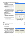
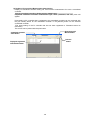
(2)
Block screen
The air-conditioners can be operated and monitored in block units using the Block screen.
Block unit
The selection menu appears
when the block is clicked.
Click the item to be selected.
Block screen
(3)
Whole building screen
The air-conditioners for the whole building can be operated and monitored using the Whole
building screen.
Whole Building Batch button
Select this for batch operation of the
whole building.
Whole building screen
(4)
When controlling the air-conditioners
and general equipment, the AirConditioner Operation and General
Equipment Operation selection screen
opens.
System equipment screen
The units other than the indoor units and general equipment are displayed on the System
equipment screen. The status (abnormal/normal) is displayed. If an air-conditioner indicated as
abnormal is clicked, the error can be reset.
* If the cause of the abnormality is not removed, the abnormality will be detected again even if the
abnormality is reset.
Selection box
Select the target to be displayed.
Selection: Centralized controller,
WHM, PLC
System equipment screen
Abnormality state
Note
Errors can be reset collectively for each centralized controller.
After the errors are reset, the units will stop and may require manual operation.
To reset errors for each group that the unit in error belongs to, set the group icon to OFF in the floor screen.
11
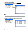
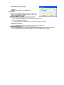
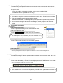
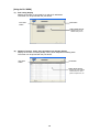
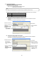
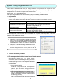
4.3 Display method for Site change display
The following is the display method for “Site change” display of wide area mode.
Use menu bar [Tool]-[Site change tool] to display “Site change” display.
Management screen
Note:
“Site change tool” can be selected only in wide area mode.
For the usage of “Site change tool”, refer to the operation manual for wide area.
4.4 Display method for Mail display
The following is the display method for “Mail” display when using the received mail tool.
Use menu bar>Tool>Mail to display “Mail” Display.
Mail tool display screen
Note:
“Mail” can be selected only when the mail function is used.
For the usage of “Mail”, refer to the operation manual for wide area.
12
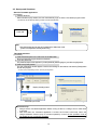
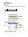
4.5 Startup and Shutdown
Start the TG-2000A application.
[Procedure]
1) Restart Windows
When Windows (OS) restarts, the user automatically logs on and the TG-2000A program starts.
* TG-2000A can also be started by selecting “TG2000” in the Windows Start Menu.
Power ON
Startup screen
Note
Use "Site change tool" to start up TG-2000A in the Wide Area mode.
(Refer to the Operation Manual (Wide Area).)
TG-2000A Shutdown
[Procedure]
1) Select the End option in the File menu in the Menu Bar
Be sure to finish this program before the shutdown.
2) Input the password.
The password input screen appears. Input the password (default:”tglogout”), and click the [OK] button.
3) Select the [Finish] button.
The end confirmation window appears. Confirm the message on the window, and click the [Finish] button
to finish this program.
* To return to the initial setting screen, click the [Cancel] button.
Display of setting screen
Password input screen
End confirmation window (with warning)
Maintenance Tip
• Always exit the TG-2000A application before turning off the PC. Failing to do so could result
in damage.
• Note that when the TG-2000A application is exited, the functions used stop. When the
charge calculation function (only for constant operation) is used, set the operation mode to
TG-2000A 24-hour continuous operation.
13
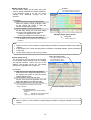
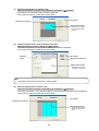
5. Initialization Before Use
The items to be set or checked at the operation start-up are shown in this chapter. Set the functions
being used.
5.1
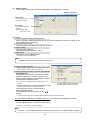
Schedule Setting
For a description of the schedule setting method, refer to chapter 7. Schedule Setting.
5.2
Air-conditioning Charge Setting
When the [Energy monitoring] button in the function selection on the normal screen is clicked, the
Air-conditioning charge screen opens.
The air-conditioning charges are initialized on this screen.
Note:
If without charge is set, "Energy monitoring" cannot be selected. (It will not appear on the screen.)
If the "Energy monitoring set-up" has already been set on the initial window, check the set details.
The license number for the “Charge” must be registered in the all centralized controllers.
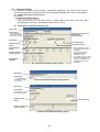
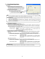
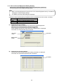
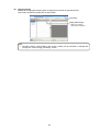
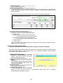
5.2.1 Charge Setting
The charge settings include the "Currency unit", "Basic charges", "Seasonal period", "Weekly charge",
"Annual charge" and "Meter charge unit" and “settlement date”. Set each item.
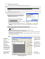
Open the Charge Set screen
[Procedure]
1) Click the [Charge set] button
Click the [Charge set] button on the air-conditioning charge screen.
2) Input the password.
Set the password (for maintenance user) on the Password screen, and then select the [OK] button.
Charge setting button
Set the charges.
Password
Set the password
(for maintenance user).
* Refer to the Site Adjustment
Manual Section 6.3 for details
on the default values.
Air-conditioning charge screen
Note:
Each item shown in the Site Adjustment
Manual Energy monitoring set-up must be
set. The power apportioning billing will not
be calculated correctly if each item is not
set.
If the charge time zone setting is changed,
the settings are valid after the changes.
The changed charge settings will be
applied
to
the
charge
calculation
immediately. When changing the settings,
be sure that the calculation for the previous
days have completed.
14
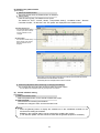
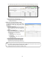
Charge set screen
(For RS-485 WHM)
Charge set screen
(For PLC WHM, PI controller WHM,
and without WHM connection)
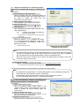
[Using the RS-485 WHM]
Set the Currency unit
[Procedure]
1) Click the [Currency unit] button.
Click the [Currency unit] button in the Charge Set screen.
The currency unit set screen opens. This screen is also
displayed when the currency Set screen is opened.
2) Select the currency unit to be used.
Click the option box of the currency unit to be used.
Otherwise, in “Etc.” column, set a currency unit
(9 characters) and the number of digits to be displayed
after the decimal point (0 to 4).
Set the electric use unit price
Set the electric use unit price. One charge system can be
selected from daytime/nighttime, weekend, seasonal charge,
etc.
[Procedure]
1) Select the charge system to be used.
Set the charge system by clicking the option button at
the charge system you want to use.
2) Select the unit price and applicable time or applicable
day of the week.
Select the unit price, applicable time, applicable
date, or applicable day of the week in accordance with
the set charge system.
Some of the data can also be input from the keyboard.
Currency unit set screen
Charge set screen
Note:
Within a time (daytime) setting cannot span days.
One within a time (daytime) setting per day is possible.
Set the standard (fixed) charge
Block units and watt hour meter units standard charge (per
month) can be set. However, for standard charge in watt
hour meter units, only the watt hour meter unit charge object
(K controller, A controller, OA processing unit, etc.) can be
set.
[Procedure]
1) Click the [Standard Charge] button.
When the [Standard Charge] button on the Charge Set
screen is clicked, the standard charge set screen
opens.
Standard charge set screen
2) Set the standard charge.
Set the standard charge in watt hour meter or block units. For watt hour standard charge, only
charge in watt hour meter units is the object.
Standard charge can be input from the keyboard by clicking with the cursor.
Clicking the standard charge allows the value to be input from the keyboard.
Note:
When there is no WHM connection the watt-hour standard charge cannot be set.
15
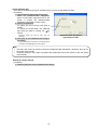
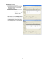
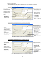
Set the settlement date
Since the air-conditioning charge is calculated once a
month, set the settlement date.
[Procedure]
1) Click [Settlement date designation] button.
When the [Settlement-date designation] button at the
screen is clicked, the Settlement-date designation
setting screen opens.
2) Specify the settlement.
To specify the end of month, click [End of month].
To specify the actual date, click [Manual] and select
the date by clicking the “ / ” buttons.
* Numerical values can also be input from the keyboard.
Settlement data designation
setting screen
Note:
The 29th, 30th, and 31st cannot be set as the settlement-date designation. (However, they can
be set as the end of month.)
Automatic printing or file output is possible after settlement-of-accounts. (Refer to the Site
Adjustment manual.)
Ending charge setting
[Procedure]
1) Click the [OK] button.
*The set details are not updated if the [Cancel] button is selected.
Note:
When an item which must be set is not set, a caution message is displayed. Reset that item.
16
[Using PLC WHM or PI controller WHM, and without WHM connection]
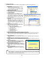
Set the Currency unit
[Procedure]
1) Click the currency unit [Change] button.
Select the currency unit [Change] button on
the Charge Set screen to open the Currency
Unit screen.
2) Set the currency unit.
Select the currency unit from the list. If the
required currency unit is not displayed in
the list, select "Etc.", and enter the currency
unit in the [Currency Unit] field. Enter the
number of decimal places in the [Number of
decimal places (0-4)] field.
3) Select the [OK] button to end the settings.
Currency unit setting screen
* If the [Cancel] button is clicked on, the settings will be
Currency unit setting
canceled and the Charge Set screen will open.
Number of decimal
places
Set the basic charges
Set the basic charges (monthly charges) for the
block unit and meter (WHM) unit.
[Procedure]
1) Select the basic charge [Change] button.
Select the basic charge [Change] button on
the Charge Set screen to open the Basic
Charge screen.
2) Set the basic charges.
* The basic charges cannot be set for the watt hour
meter used for the air conditioner unit.
3) Select the [OK] button to end the settings.
* The set details are not updated if the [Cancel] button
is selected.
Basic Charge setting screen
Basic charge
Set the basic charge (monthly
unit) for the block and meter unit.
Note:
This setting screen does not appear when using the power apportioning billing (manual electric
amount input) with no WHM connected.
If the basic charge is 0 when the [OK] button is selected, a message appears. Check the
settings in this case.
Set the seasonal period
Set the validity of the seasonal period, and the period that the season is applied.
[Procedure]
1) Select the seasonal period [Change] button.
Select the seasonal period [Change] button
on the Charge Set screen to open the
Seasonal period Setting screen.
2) Set the validity of the seasonal setting and
the period.
Select the validity of the seasonal charge
setting, and if valid, set the period.
3) Select the [OK] button to end the settings.
* The set details are not updated if the [Cancel] button
is selected.
17
Seasonal period setting screen
Weekly charge set-up
Set the weekly charge unit and each day's time
zone for normal operation and season operation.
If the seasonal period is not set, the "Usual
charges" and "Seasonal charges" can be
selected.
[Procedure]
1) Select the weekly charge [Change] button.
Select the weekly charge [Change] button
on the Charge Set screen to open the
Weekly Charge Setting screen.
2) Set the charge unit and charge zones.
Set the daily charge time zone and charge
unit for the normal and season operation.
Charge unit: Maximum five units
Time zone: Maximum 10 zones (per day)
3) Select the [OK] button to end the settings.
* The set details are not updated if the [Cancel] button
Set button
The charge unit time zone can be
set, copied, pasted or canceled.
Weekly Charge setting screen
Charge unit
Set the charge unit.
is selected.
Note:
Refer to section 9.4 Air-conditioner charge setting for details on setting the details of the weekly
charges.
If the charge unit is 0 when the [OK] button is selected, a message appears. Check the settings
in this case.
Set the meter charge unit when using a meter.
Annual charge set-up
The charge time zone for days that do not apply
to the weekly charge settings, such as holidays
and summer vacation, can be set. Up to five
patterns, and 50 days can be set. The weekly
charge unit is applied as the charge unit.
Pattern Set/Change button
The setting window for setting
the annual pattern opens
when this button is clicked.
[Procedure]
1) Select the annual charge [Change] button.
Select the annual charge [Change] button on
the Charge Set screen to open the Annual
Charge Setting screen.
2) Set the pattern and assign the date.
Set the time zone and applicable unit, and
assign the pattern to the date to be set.
3) Select the [OK] button to end the settings.
* The set details are not updated if the [Cancel]
button is selected.
Annual Charge setting screen
Annual setting states
The state of the annual charge settings is
displayed.
Blue
: Settings for corresponding pattern
Light blue : Settings for other pattern
Note:
Refer to section 9.4 Air-conditioner charge setting for details on setting the details of the annual
charges.
18
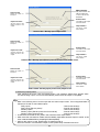
Set the settlement date
Since the air-conditioning charge is calculated once a month, set the settlement date.
[Procedure]
1) Click [Settlement-date designation] button.
When the [Settlement-date designation]
button at the bottom right-hand side of the
screen is clicked, the Settlement-date
designation specification screen opens.
2) Specify the settlement.
To specify the end of month, click [End of
month].
To specify the actual date, click [Manual]
and select the date by clicking the “ / ”
buttons.
* Numerical values can also be input from the
keyboard.
3) Click [OK] to end settlement-date designation setting.
Settlement data designation
specification screen
* If the [Cancel] button is clicked on, the settings will be
canceled and the Management screen opens.
Note:
The 29th, 30th, and 31st cannot be set as the settlement-date designation. (However, they can be
set as the end of month.)
Automatic printing or file output is possible after settlement-of-accounts. (Refer to the Site Adjustment manual.)
Ending the charge settings
[Procedure]
1) Select the [OK] button when completed with the settings.
19
6. Normal Operation
6.1
Monitor/Operation
Perform normal operation from the Management screen.
Display the Management screen by clicking the [Monitor/Operation] function select button (top
left-hand side of screen), then selecting the operation object from the display units buttons (top
right-hand side of screen). The “Cumulative time” and “Energy monitoring” are displayed when with
charge function is selected.
Function selects
Display units
Floor switching button
(1)
Select the function
When the [Monitor/Operation] function select button is
Display units buttons
clicked, the monitor/operation screen opens.
Function select button
(2) Select the operation object.
[Procedure]
When group is the object
Operations from floor buttons
Click the [Floor] button in screen display.
Select the distribution floor of the object group from
the floor switching box (left-hand side of screen).
Click the object group icon on the displayed floor.
Operations from Whole floor screen
Select the whole floor by scrolling from the Sub screen.
Click on the target floor from the Sub screen (whole floor).
Click the object group icon on the displayed floor.
When whole floor is the object
Click the [Floor] button in screen display.
Monitor/operation screen
Select the object floor from the floor switching box.
Click the [Floor batch process] button at the bottom right-hand corner of the screen.
When block is the object
Click the [Block] button in screen display.
Select the object block from the monitor/operation screen.
When whole building is the object
Click the [Whole building] button in screen display.
Click the [Building batch process] button at the bottom right-hand corner of the screen.
When system equipment or Centralized controller is the object
Click the [System equipment] button in screen display.
Select the centralized controller connected to the object equipment from the centralized
controller selection box pull down menu.
Select the object system equipment from the monitor/operation screen.
6.2
On/Off Operation
Air conditioner On/Off operation is possible.
Block, floor batch, whole building, and other multiple group batch operations are also possible.
Operable objects: Group, floor batch, block, whole building
[Procedure]
1) Select the object to be turned on or off.
Click the on/off object. A menu appears.
Note:
For a description of the underlined part, refer to section
“6.1 (2) Select the operation object” to be operated.
Example) Group operation
20
2) Select on/off.
If the selected object is currently running, [OFF] is displayed in the menu and if the selected
object is stopped, [ON] is displayed in the menu.
When [ON] or [OFF] is selected from the menu, operation is switched.
Note:
When multiple groups are the operation object, if at least one group is on, OFF operation has
precedence.
Those ventilation units connected to air conditioners will turn on and off according to the on/off action of the
air conditioners.
How the ventilation units behave depends on the versions of the TG-2000A, Cntralized controller.
【If connected to an AG-150A ver. 2.30 or later, or to an AE-200, AE-50 or EB-50】
Air conditioner On/Off
Ventilation unit
operation
On/Off action according to air
(w/connection to ventilation
Fan speed
conditioner operation
units)
The fan speed ([Hi]/[Lo]) previous to the
On
On
air conditioners’ On/Off status change is
maintained.
Off
Off
【All other version combinations】
Air conditioner On/Off
Ventilation unit
operation
On/Off action according to air
(w/connection to ventilation
conditioner operation
units)
6.3
On
On
Off
Off
Fan speed
If the fan was on before air conditioners
turned on: The fan speed ([Hi]/[Lo])
previous to the air conditioners’ On/Off
status change is maintained.
If the fan was off before air conditioners
turned on: The fan will operate at [Lo].
-
Operation Status Monitor
The air conditioner operation status can be monitored.
Operable objects: Floor, block, whole building, system equipment
(1) Display the operation status.
[Procedure]
1) Select the object whose operation status is to be displayed.
When the object whose operation status is to be displayed is clicked, the current operation
status is displayed.
Note:
For a description of the underlined part, refer to section “6.1 (2) Select the operation object”
to be operated.
21
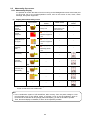
(2) Description of operation status
Floor display screen
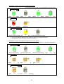
Description of group icons (Air conditioner)
[Icon color] Green:On, Gray:Off, Orange:Error
Operation state
[Air conditioner group : On]
[Air conditioner group : Off]
[Ventilation group : On]
[Ventilation group : Off]
[Air conditioner group : On
Interlocking ventilation unit : On]
[Air conditioner group : On
Interlocking ventilation unit : Off]
[Air conditioner : Off
Interlocking ventilation unit : On]
[Air conditioner group : Off
Interlocking ventilation unit : Off]
[Air conditioner group :
Night setback On]
[Air conditioner group :
Room temp. display]
[Air To Water (PWFY)
group : On]
[Air To Water (PWFY)
group : Off]
Error state
[Air conditioner group error]
[Ventilation group error]
[Centralized controller error]
[Expansion controller error]
[Outdoor unit error]
[Subsidiary outdoor unit error]
[BC controller error]
[HBC controller(main) error]
[HBC controller(sub) error]
[K-transmission converter error]
[Local remote controller
operation: Prohibited]
[With schedule setting]
[Schedule disabled]
[Filter sign]
[Air To Water (PWFY) group :
Check water circuit]
[Operation prohibited state]
[Operation mode display]
[Display of group name]
[Air To Water (PWFY) group error]
Other state & display
[Energy save control]
*1: Icons on the screen may differ depending on the group icon settings.
*2: The room temperature of the air conditioner group appears only when the "Display of room temp." is set to
"Activate" or "Drive only" in the user setting.
Note
In the combination system of AE-200/AE-50, after recovery from the power outage or LAN
communication error of the AE-50, about 10 minutes, icons of the air-conditioner which is
connected to the AE-200 will be (orange) abnormal display, you will not be able to operate.
Then, abnormal display is released, to return to the operation possible.
22
Note:
When the mouse cursor is placed on the group icon, the group Full name is displayed.
At stop, the operation mode and set temperature displays are hidden. (Gray characters display)
When the indoor unit is in the operation prohibited state, it remains stopped.
To reset the operation prohibited state, change the operation mode.
Some models are unable to display this operation prohibited state.
The filter sign is displayed only on the Filter sign screen.
There may be a slight time lag in the marks displayed during energy saving control and the actual operation
state. While on stand-by for energy save control, the “tree” symbol will not be displayed. If G-50A of Ver.2.90 or later and
AE-200/AE-50/EB-50/AG-150A/GB-50AD are connected, the tree symbol will be displayed while outdoor units are
under the control.
If “Display of room temp.” in the user setting is set to “Drive only”, the room temperature is displayed only when
air conditioning unit group is in operation. For Air To Water Booster Unit and Air To Water HEX Unit, the room temperature
is always displayed even when “Display of room temp.” is set to “Drive only.”
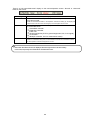
Explanation of group icons(instrumental equipment)
[Icon color] Gray:Normal, Orange:Error
Operation status
[Thermometer/normal]
(Red display) *1
[Hygrometer/normal]
[Thermometer/detection limit]
(Red display) *1
[Hygrometer/detection limit]
Error status
[Thermometer abnormal]
[Hygrometer abnormal]
*1:Temperature value and humidity value are displayed in red when upper/lower limit warning is detected.
However, the temperature and humidity values are not displayed in red when the alarm display setting
of AI controller is set to "Deactivate". The icons are also not displayed in orange in this case.
Explanation of group icons (DC for general equipment)
[Icon color] Color:On, Gray:Off, Orange:Error
Operation state
[General equipment ON]
[General equipment OFF]
Error state
[General equipment error]
[Centralized controller error]
[Expansion controller error]
Other state & display
[Schedule setting enabled]
[Schedule disabled]
23
[General equipment name display] [Hide ON/OFF display]
Explanation of group icons (PLC for general equipment)
[Icon color] Green:On, Gray:Off, Orange(Default settings):Error *1
Operation state
[General equipment ON]
[General equipment OFF]
[Operation/monitor display]
[Operation display only]
Error state
[General equipment error]
[PLC error]
Other state & display
[Schedule setting enabled]
[Error details display *2]
[General equipment name display]
*1: The icon color is displayed in different color if the icon display color setting for general equipment is changed.
*2: Error state display can be set randomly. (Maximum: 8 characters)
Explanation of group icons (general equipment for IC I/O signal)
[Icon color] Green:On, Gray:Off, Orange:Error
Operation state
[General equipment ON]
[General equipment OFF]
[Operation/monitor display]
[Centralized controller error]
[Expansion controller error]
Error state
[General equipment error]
Other state & display
[Error details display *1]
[General equipment name display]
*1: Error state display can be set randomly. (Maximum: 8 characters)
24
[Operation display only]
(3)
Block screen
The details displayed on the Block screen are explained below.
Block name
Display the object block name.
Operation state
Display the operation state of
the object block. “ON” is
displayed when one or more
groups are in operation.
Floor name
Display the floor name on
which the object block is
installed. Note that this is
blank when several
blocks are selected.
Operation mode
Display the operation mode
of the object block.
Note that this appears only
when all groups match.
Block unit display screen
Note:
Block does not correspond to the “Only running ventilation unit on” display.
The general equipment (PLC) is not block targets.
The operation state is not displayed if the block consists of general equipment (DIDO)
groups whose “Display ON/OFF character string” setting is set unchecked.
(4)
Whole building display screen
The details displayed on the Whole building display screen are explained below.
[Air-conditioner group,
General equipment (DIDO) group display]
(Including Air To Water (PWFY))
(Green)
: Running (On)
(Deep gray) : Stopped (Off)
(Blue)
: Only running ventilation unit on
(Orange)
: Abnormal
[General equipment
(PLC and IC I/O signal) display]
■ (Green)
: Running (On)
■ (Deep gray) : Stopped (Off)
■ (Orange) : Abnormal
Floor name
Display the floor
name.
Status display
Display the status of the
air-conditioning group and
general equipment.
Order:Air-conditioning
Group
General equipment
General equipment
display
Measuring meter
equipment display
[Measuring meter equipment display]
■ (Green)
: Normal
■ (Red)
: Abnormal
Floor unit display screen
Note:
The icon display of air-conditioner group is also used for the general equipment connected to
DIDO controller.
The icon display of general equipment is also used for the PLC and IC I/O signal.
(5)
System equipment display screen
When an equipment is abnormal, is displayed
at the icon of the abnormal equipment.
25
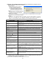
6.4
Operation Details
Air conditioner operation mode switching, temperature adjustment, and other functions can be
monitored and operated. Objects which can be monitored and operated: Floor, block, whole building
(1) Display the remote control screen.
[Procedure]
1) Select the operation setting.
Click on the group icon, floor batch, block or whole building batch button, and then select
[Properties] from the menu. The Operation setting screen opens.
(2)
Description of operation setting screen
Object name
On/Off button
The air-conditioner
(ventilation unit) can
be turned On and Off.
Interlocking ventilation unit
On/Off button
Fan speed button
Mode button
Fan speed setting
Ventilation mode
button
Air direction setting
Set temperature/
display
Prohibit operation by
remote controller
Set temperature
range limit
Air-conditioner operation setting screen
* When Fahrenheit is chosen
by Centralized controller, “°F”
is displays.
* It may not be displayed
depending on the air
conditioner model.
* For multiple groups, the state
where it is in agreement for
every item is displayed. It is
not displayed when not in
agreement.
Object name
On/Off button
The general equipment can be turned
On and Off.
General equipment operation setting screen
Object name
On/Off button
The ventilation unit can
be turned On and Off.
Ventilation mode
Fan speed setting
button
Prohibit operation by
remote controller
Ventilation unit operation setting screen
26
Object name
On/Off button
The Air To Water
(PWFY) can be turned
On and Off.
Mode button
Set temperature/
display
Prohibit operation by
remote controller
Air To Water (PWFY) equipment operation setting screen
Item
Object name
On/Off button
Mode button
Ventilation mode button
Details
Group
: Display the group name (Full).
Floor (batch)
: Display the floor name.
Block
: Display the block name.
Whole buildings
: Display whole buildings.
General equipment : Display the general equipment name (Full).
Display the current On/Off state. (The state for which the button is pressed indicates
the current state.)
Display the current operation mode. (The state for which the button is pressed
indicates the current state.)
The current mode of the Ventilation unit will appear. (The state for which the button is pressed
indicates the current state.)
* On the Air-conditioner operation setting screen, ventilation mode will appear only on TG-2000A
Ver. 6.38 or later.
On the Ventilation unit operation setting screen, ventilation mode will appear regardless of the TG-2000A
version.
Interlocking ventilation unit
On/Off button, Fan speed
button
Display the current On/Off and fan speed state. (The state for which the button is
pressed indicates the current state.)
TG-2000A ver.6.20 or later:
The ON/OFF status and the Fan speed ([Hi][Lo]) will appear.
TG-2000A ver.6.10 or earlier:
The operation status ([Hi][Lo][Stop]) will appear.
* Note that it is not displayed for groups to which the interlocking ventilation unit is not connected.
Set temperature/display
Air direction setting
Fan speed setting
Prohibit operation by
remote controller
Set temperature range
limit
Set temperature
: Display the set temperature.
* The set temperature is displayed in 1°C units.
Indoor temperature : Display the current indoor temperature.
Water temperature
: Display the current water temperature.
(Updated in approx. three minutes.)
Display the current air direction.
Display the current fan speed.
Display the operation prohibit setting state of the local remote controller.
* Only the operation prohibited setting from the man-machine and the centralized controller is reflected
upon display.
Display the lower and the upper limit of the set temperature for the Cool (Dry) mode,
for the Heat mode and for the Auto mode. (valid for ME remote controller and for
simple ME controller)
* The set temperature range is limited on the ME remote controller and individual browser's operation
screen.
* Only the lower limit of the set temperature for the Cool (Dry) mode and the upper limit for the Heat mode
can be set with the PAR-F27MEA-E.
* For ME remote controller, model name is written on the packing label or on the notice sticker on the
backside of the remote controller lid. For ME simple remote controller, model name is written on the
packing label or on the rated nameplate of the remote controller.
27
(3) Operation setting screen operation
Operation methods are shown below.
Item
Details
Click either the [ON] button or [OFF] button.
ON/OFF change
The current state can be maintained without selecting both buttons.
For the air conditioner, click the [Cool], [Dry], [Fan], [Heat], or [Auto] button.
Mode change
For the Air To Water (PWFY), click the [Heating], [Heating ECO], [Hot Water],
[Anti-freeze], [Cooling] button. (In the Air To Water Booster unit, Cooling is nothing.)
The current state can be maintained without selecting all the buttons.
* Temperature setting cannot be set for [Fan] or [Heating ECO].
* Note that some modes may not be able to be set depending on the equipment model connected.
* For K control models, all modes are displayed; however, choose only the modes that can be used.
Ventilation mode change
For the ventilation unit, click the [Bypass], [Heat-recovery], or [Auto] button.
* Note that some modes may not be able to be set depending on the equipment model connected.
Changing the interlocking
ventilation unit On/Off, Fan
speed
Details of operation and fan speed are set on the interlocking ventilation unit.
Click the operation button ("ON" or "OFF") and the fan speed button ("Hi" or "Lo"), or leave the buttons
unselected (maintains the current status).
Depending on the version of the centralized controllers to be connected, the operational details of the
interlocking ventilation unit may differ.
AG-150A/GB-50ADA ver. 2.30 or later, AE-200, AE-50 or EB-50:
If the fan speed is not set for unit operation, you can run the unit with the fan speed unchanged.
(The fan speed can be changed for the "Stop" interlocking ventilation setting. However, this stops
interlocking ventilation but does not change the fan speed setting. The changed fan speed setting is
retained on the centralized controller.)
AG-150A/GB-50ADA ver. 2.30 or later, G-50A:
If the interlocking ventilation unit operating state is changed from stopped to running and the fan speed is
not selected, the setting used is "ON" with the fan speed set to "Lo".
Set temperature change
Change the set temperature by clicking set temp. adjustment “ / ” buttons.
Air direction change
Click the “ / ” buttons to change the air direction.
* This function is only provided for ventilation unit, not for interlocking ventilation units.
* The range of temperatures that can be changed depends on the operation mode. This function is not
provided for the ventilation group.
* When displayed in Celsius, the temperature setting is in 1°C increments.
* When displayed in Fahrenheit, 2°F steps or 1°F step depends on the indoor unit function to be connected.
* If the indoor unit supports the dual set point function in the Auto mode and when the operation mode above is set to
Auto or Setback, two set temperatures for Cool mode and Heat mode can be set.
* On TG-2000A Ver. 6.40A or later, set the Mode before making the settings for Set temperature.
Horizontal
20% vertical 60% vertical 80% vertical 100% vertical
Swing
Auto
Keeping current state
* Swing and air direction change are provided on different equipment models.
* This function is not provided for the ventilation group and the Air To Water (PWFY).
Fan speed change
Click the “ / ” buttons to change the fan speed.
Settable fan speed differs between the Air conditioner group and the Ventilation unit group.
Air conditioner
Ventilation unit
Low
Low
Middle-2
Low
Middle-1
Low
High
High
Auto
Auto
Keeping current state
Keeping current state
* The fan speed can be changed to 2, 3, 4 stages or AUTO depending on the equipment model.
* This function is not provided for the Air To Water (PWFY).
Prohibit operation by
remote controller change
The setting is changed to Permit, Prohibit, Keeping current state (without icon
displayed), and Permit each time when each button for [On/Off], [Mode], [Set
temperature], [Filter reset] ([Check water] in case of Air To Water (PWFY)), [Air
direction], [Fan speed] and [Timer] is pressed.
Local remote control operation Prohibit/Permit
When Unchange (no icon display) is selected, Prohibit/Permit remains in the current
state.
* For the ventilation group, it is possible to set Permit/prohibit only to [On/Off] and [Filter reset].
* For the K-control model, there is no item provided for [Filter reset], [Air direction], [Fan speed] and
[Timer].
* For the K-control model, it is possible to set only All-item permit and All-item prohibit.
* [Air direction], [Fan speed], and [Timer] may not be displayed, depending on the unit model.
28
Operation methods (continued)
Item
Set temperature range
limit
Details
Set the temperature range limit value by selecting the Maximum or the Minimum
buttons.
Change the set temperature range limit value by clicking the " / " buttons.
Cooling (dry) mode :Upper limit set temperature, Lower limit set temperature
Heating mode
:Upper limit set temperature, Lower limit set temperature
:Upper limit set temperature, Lower limit set temperature
Automatic mode
When the Maximum or the Minimum buttons are not selected, the upper limit or the
lower limit will be removed.
* This can be set only when the set temperature range limit function is valid.
* The set temperature range is limited only for the ME remote controller (PAR-F27ME) and personal
browser. In some case, this function cannot be used depending on the indoor unit model being used
when using the MA remote controller (*1).
* It is impossible to set the upper limit lower than the lower limit. When the upper limit is lower than the
lower limit, the limit will automatically change to “upper limit = lower limit”.
* When the out of range setting is made on the remote controller, the system will correct the value
automatically to the settable value.
* When displayed in Fahrenheit, the temperature is displayed in 2°F steps.
* The set temperature limit range for the Auto mode cannot be set for the groups that support the dual set point
function in the Auto mode. The set temperature ranges for the normal cooling and heating modes will be used for
the ones for cooling and heating in the Auto (dual set point) mode.
Select [OK] or [Cancel]
button.
OK
: Accepts the changes and returns to the monitor/operation screen.
Cancel: Ignore the changes and returns to the monitor/operation screen.
*1: The followings are the applicable MA remote controllers. However, this function may not be available depending on the indoor unit model
(e.g, A control type and Room Air Conditioner).
MA smart remote controller (PAR-30MAA, PAR-31MAA)
MA smooth remote controller (PAR-21MAA)
MA compact remote controller (PAR-YT51CRB, PAC-YT52CRA, PAC-YT53CRA)
Note:
If a group in a different state exists on the operation setting group of All floors, Whole buildings, and
Block, the following is displayed.
On/Off : State in which both ON button and OFF button are not pressed (keeping current state)
Mode : State in which all operation mode buttons are not pressed (keeping current state)
Set temperature : – – (keeping current state)
Remote controller prohibited item: No display (keeping current state)
Set temperature range limit: – – (keeping current state)
On the “Whole floor,” “Whole building,” and “Block” windows on which air conditioning units (the
ones interlocked with ventilation units) and uninterlocked ventilation units coexist, use the same
ON/OFF and the Fan Speed (▲/▼) buttons as for the air conditioning units to operate the
uninterlocked ventilation units. They are not for operating the interlocked ventilation units.
Note that the setting/change contents of each item may change depending on the equipment
model. It is possible to confirm the group function by reading the [System configuration setting
display] in the [Display] menu. (For operation details, refer to the Chapter 10 System display given
in this instruction manual.)
When the air direction is set to downwards, the indoor unit control may automatically change it to
another direction.
When local remote control operation is prohibited, “CENTRALLY CONTROLLED” is displayed on
the local remote controller.
29
When Fahrenheit is chosen by Centralized controller
6.5
Other Functions
The following are displayed on Floor screen of the monitor/operation screen:
Full name
Block name (Operation block name)
Charge block name
Energy saving/Peak cut control information
[Procedure]
1) Select group.
When the group item of the group whose names are to be displayed is clicked, a menu appears.
2) Select the information to be displayed.
When Information in the menu is clicked, every set contents are displayed.
3) Select [OK] button.
Confirm the contents of the information and then click the [OK] button.
30
Note:
When a communication error occurs, “???” appears on the screen. Energy saving/Peak cut
information can be seen when the information screen is displayed. As the control information is
monitored every minute, display the information menu again after a minute.
The energy saving/peak-cut control is sometimes run at regular intervals. The type of information
displayed will depend on whether the unit is under the control or on stand-by. Information related
to the control of indoor units and outdoor units will be displayed.
“Peak cut control”
<Under the control>
●Information screen display
“Level* under control”
●Floor-screen icon
<On stand-by>
●Information screen display
“Level* under control”
●Floor-screen icon
The levels are shown where
marked with an asterisk (*).
“Energy save control”
<Under the control>
●Information screen display
“Under control”
●Floor-screen icon
<On stand-by>
●Information screen display
“Under standby”
●Floor-screen icons
The full group name automatically appears when
the cursor is placed on the group icon.
31
7. Schedule Setting
The operation mode, temperature, wind velocity, and On/off from the specified time can be set with the
schedule setting function. To set a schedule, “On (start)” or “Off (stop)” must always be selected.
Today’s schedule, weekly schedule or annual schedule can be set. A schedule for each day can be set
in the weekly schedule, and a schedule for up to 50 days can be set in the annual schedule. The setting
priority is today’s, annual and weekly.
The minimum unit that can be set is group.
Operable objects: Group, floor, block, whole building
Note:
The “Annual Schedule, Weekly Schedule” license must be registered in the centralized
controller before using this schedule function. The schedule cannot be used until the license is
registered in the centralized controller.
When using TG-2000A Ver. 6.20 or later, the “Weekly 1” (except the “Seasonal settings”)
function is available for use, even if the “Annual/Weekly Schedule” license for the connected
AE-200/AE-50/EB-50/AG-150A/GB-50ADA has not been registered.
With the general equipment, only the schedule for the group connected to PLC for general
equipment unit and whole building can be set. The license does not need to be registered. Up
to 12 events can be scheduled. Seasonal setting is not available on weekly schedule.
The schedule function cannot be used with general equipment connected to the IC I/O signal.
Use the Annual schedule to set the holidays that are not applied to Weekly schedule.
(Ex: Set the schedule to OFF only.)
Important (Caution)
When an On/Off schedule for the air-conditioner is set at a time when the unit price changes,
the timing may result in an invoice being issued for air-conditioning charges at the incorrect
unit price.
(Example) Unit price 1: 08:00-17:00
Tenants not invoiced
Unit price 2: Times other than the above Tenants invoiced
In the schedule, the air-conditioner stops at 17:00
Due to the timing, the operating time is added at unit price 2 when the air-conditioning charges are
invoiced.
To prevent invoicing at the incorrect unit price for air-conditioning charges, run scheduling so that the
Note that the schedule setting details differ depending on the centralized controller model used.
Number of settings for
schedule
Air direction and Fan
speed setting on the
schedule
Seasonal setting on
Weekly schedule
AE-200/AE-50/EB-50
Up to 24 settings can be set.
AG-150A/GB-50ADA
Up to 24 settings can be set.
G-50A
Up to 12 settings can be set.
Air direction and Fan speed
can be set.
Air direction and Fan speed
can be set.
The unit can make weekly
schedule setting for five
seasons.
AG-150A Ver.2.80 or later
The unit can make weekly
schedule setting for five
seasons.
Before AG-150A Ver. 2.80
The unit can make weekly
schedule setting for two
seasons.
AG-150A Ver.1.20 or later
The schedule automatically
starts the operation prior in
order to reach the specified
temperature at the specified
time.
AG-150A Ver. 2.90 or later
The schedule function for
each group can be enabled
or disabled.
The unit does not have
functions as Air direction and
Fan speed setting.
The unit does not have
function as
seasonal setting.
Optimized start
The schedule automatically
starts the operation prior in
order to reach the specified
temperature at the specified
time.
Schedule
Enable/Disable
The schedule function for
each group can be enabled
or disabled.
(EB-50 does not support this
function.)
32
The unit does not have
function as Optimized Start.
The unit does not have
function as Schedule
Enable/Disable.
Note:
On TG-2000A Ver. 6.38 or later, Weekly schedule settings can be set for five seasons,
regardless of the AG-150A version. On AG-150A before Ver. 2.80, Weekly schedule
settings can be set only for two seasons.
On AG-150A Ver. 2.80 or later, before setting the Weekly schedules, check that the Seasonal
settings on the AG-150A are set to “Available.” The Weekly schedule settings on the AG-150A
will be effective only when the Seasonal settings on the AG-150A are set to “Available.”
When “AE-200, AE-50, EB-50, AG-150A, GB-50ADA” and “G-50A” are connected in the same system,
the unit connected to “AE-200, AE-50, EB-50, AG-150A, GB-50ADA” and the unit connected to “G-50A”
cannot make the settings at the same time because they have different setting contents.
The selection of AG-150A” or G-50A is displayed for schedule setting of floor, block or whole building.
Make each schedule setting after selecting one of them.
(When “AG-150A” is selected, the settings apply to units connected to an "AE-200, AE-50, EB-50,
AG-150A or GB-50ADA".)
33
7.1
Today’s Schedule Setting
1) Select the today’s schedule.
When the today’s schedule is clicked on in the
menu, the today’s schedule set screen opens. The
information saved in the integrated centralized
control software TG-2000A appears on the screen.
Perform the following operations from the
today’s schedule set screen.
Note:
If “AE-200, AE-50, EB-50 or GB-50ADA” and “G-50A” units are connected in combination in
the schedule settings for a floor, block or whole building, the AG-150A or G-50A selection is
displayed. Select one and then set the various schedules.
(“AG-150A” units: Units connected to an AE-200, AE-50, EB-50, AG-150A or GB-50ADA)
(1)
Schedule setting
Caution:
Press the [Update] button to display the schedule set in the centralized controller on the monitor
before setting the schedule.
Mistakes in the schedule setting can be prevented by updating the monitor.
[Procedure]
1) Select the Date button.
The menu opens when the Date
(year/month/day) button is clicked on.
2) Select Setting.
The schedule details set screen opens when
the menu [Setting] is clicked on.
3) Set the time.
Set the time with the “ /” buttons. The
value can also be input directly.
* The values can also be input directly.
Monitor update button
The schedule setting details are
monitored from the centralized controller
or general equipment.
Note:
Multiple schedules cannot be set for the same time.
Setting button
A menu appears when the
date is clicked. Click the
"Setting" button.
4) Select the [ON] or [OFF] ([Optimized start]) button.
Click the [ON] or [OFF] button. The current state can be set without selecting either the [ON] or
[OFF] button.
[Optimized start] button is displayed for the applicable groups connected to AE-200/AE-50
/EB-50/AG-150A/GB-50ADA.
Click the [Optimized start] button to set the operation mode and the set temperature for the
schedule settings for this function.
5) Set the operation prohibit, mode and set temperature, etc.
The operation prohibit item can enable or disable operations from the local remote controller.
Set either prohibit or enable for the On/Off, mode and set temperature items.
* If changes are not required, set the current state (no icon display).
Use each mode button to select the mode. To set the current state, do not select any button.
The temperature can be set by clicking the [Set Temperature] button.
The temperature can be changed with the “ / ” buttons. To set the current state, click the [Set
Temperature] button again to cancel the selection.
34
For AE-200/AE-50/EB-50/AG-150A/GB-50ADA only (The setting is not displayed for G-50A)
Click the “▲/▼” buttons to make Air direction setting.
Click the “▲/▼” buttons to make Fan speed setting.
To delete a set schedule, click the [Delete] key.
On/Off button
Set the On/Off or Optimized
start state
Time setting button
Set the schedule
time.
Ventilation mode button
Set the ventilation mode.
Mode button
Set the mode.
Delete button
Delete a schedule
setting.
Fan speed button
Set the fan speed.
Air direction button
Set the air direction.
Set temperature button.
Set the set temperature.
When using the "Heating"
mode, a temperature
o
higher than 12 C can be
set as the frost protection
function.
Operation prohibit/enable
button
Set whether operation of the
local remote control is
prohibited or enabled.
Air-conditioner schedule details setting screen
On/Off button
Set the On/Off state
Time setting button
Set the schedule
time.
Mode button
Set the mode.
Delete button
Delete a schedule
setting.
*Air direction setting and Fan speed
setting are not displayed when
G-50A is connected.
Set temperature button.
Set the set temperature.
When using the "Heating"
mode, a temperature
o
higher than 12 C can be
set as the frost protection
Operation prohibit/enable
button
Set whether operation of the
local remote control is prohibited
or enabled.
[G-50A] Air-conditioner schedule details setting screen
Time setting button
Set the schedule
time.
Delete button
Delete a schedule
setting.
On/Off button
Set the On/Off state
General equipment schedule details setting screen
On/Off button
Set the On/Off state
Time setting button
Set the schedule
time.
* Fan speed setting is not
displayed when G-50A is
connected.
Delete button
Delete a schedule
setting.
Fan speed button
Set the fan speed.
Ventilation mode button
Set the ventilation
mode.
Operation prohibit/enable
button
Set whether operation of the
local remote control is
prohibited or enabled.
Ventilation unit schedule details setting screen
35
On/Off button
Set the On/Off state
Time setting button
Set the schedule
time.
Mode button
Set the mode.
Delete button
Delete a schedule
setting.
Set temperature button.
Set the set temperature.
Operation prohibit/enable
button
Set whether operation of the
local remote control is
prohibited or enabled.
Air To Water (PWFY) schedule details setting screen
6) Click the [OK] button after making the settings.
The set schedule appears on the current day schedule set screen.
* The set details are invalidated when the [Cancel] button is clicked on.
Note:
Up to 24 settings can be set when AE-200/AE-50/EB-50/AG-150A/GB-50ADA is connected.
Up to 12 settings can be set when G-50A is connected.
When using batch schedule monitor for two or more groups, the setting field is highlighted in
light blue if there are different settings. (On Schedule setting screen)
If the data is sent without today's schedule set, a schedule with "no settings" is set. A
schedule mark appears at the group icon in this case.
When using the "Heating" mode, a temperature higher than 12oC can be set as the frost
protection. (The function of Frost protection is only at the time of effective.)
* This can be used only with the PAR-F27MEA, PAR-21MAA, or PAR-30MAA system.
o
* Only CITY MULTI models except for PUMY are supported. The setting must be over 17 C unsupported models and
old CITY MULTI models.
When Fahrenheit is chosen by Centralized controller, the temperature unit displays by "oF".
All modes are displayed for old K control models and M-NET models before FREE PLAN
models. However, choose only the modes that can be used.
(2)
Schedule change
Use this function to change a set schedule.
[Procedure]
1) Select the current day schedule from the menu.
The current day schedule set screen opens.
2) Select the operation display box.
Click the operation display box to be changed.
The schedule details set screen opens.
Operation display box
* Change the time by
dragging.
3) Change the details of the schedule.
Set the changes on the Schedule details setting screen.
* For the operating instructions, refer to “(1) Schedule setting”.
When only the set time is changed, the change can be made by dragging the
operation display box. (10 minutes units)
4) Click the [OK] button after making the settings.
The changed schedule appears on the current day schedule set screen.
* The set details are invalidated when the [Cancel] button is clicked on.
36
(3) Schedule clearing
[Procedure]
1) Select the Date button.
The menu opens when the Date button is clicked on.
2) Select [Clear].
Select [Clear] from the menu.
The clear check screen opens.
3) The schedule is deleted when [OK] button is pressed
after confirmation.
* The schedule is not deleted when the [Cancel] button is clicked on.
(4) Checking the schedule details
[Procedure]
1) Select the Date button.
The menu opens when the Date button is clicked on.
2) Select View.
Click the menu [View].
The details screen opens.
The details for “Time”, “On/Off”, “Mode”, “Temperature Setting”, “Ventilation mode”, “Remote
Controller Prohibit”, ”Air direction” and “Fan speed” are displayed on the details screen.
Operation display box
* The Schedule details setting
screen opens when clicked,
and the schedule can be
changed.
Set time button
* The Schedule details setting
screen opens when clicked,
and the schedule can be
changed.
3) Press the [OK] button after confirming or changing the settings.
* The set details are invalidated when the [Cancel] button is clicked on.
Ending the today’s schedule setting
Select the [Send] or [Cancel] button.
Send : The schedule is sent to the centralized controller, and the monitor/operation screen opens.
Cancel : The schedule is not sent to the centralized controller, and the monitor/operation screen opens.
(When the monitor/operation screen opens, a schedule mark is displayed at the set group's icon.)
37
7.2
Weekly Schedule Setting
Seasonal settings can be set on Weekly Schedule with AE-200/AE-50/EB-50/AG-150A/GB-50ADA.
Up to two types of settings can be set for Seasonal setting.
Refer to (1) Seasonal settings for the setting method.
*The “Weekly 1” (except the “Seasonal settings”) function is available for use, even if the “Annual Schedule, Weekly Schedule”
license for the connected AE-200/AE-50/EB-50/AG-150A/GB-50ADA has not been registered. (Applicable to TG-2000A ver.
6.20 or later)
G-50A does not have the function as the seasonal setting. Refer to (2) Schedule setting or later
section.
Switch from Management screen to schedule set screen
[Procedure]
1) Select weekly schedule.
When Weekly schedule is selected from the menu,
the Weekly schedule set screen opens.
Perform the following operations from the
Weekly schedule set screen.
Note:
If “AE-200, AE-50, EB-50 or GB-50ADA” and “G-50A” units are connected in combination in the
schedule settings for a floor, block or whole building, the AG-150A or G-50A selection is
displayed. Select one and then set the various schedules.
(“AG-150A” units: Units connected to an AE-200, AE-50, EB-50, AG-150A or GB-50ADA)
(1) Seasonal settings
(G-50A does not have this setting.)
[Procedure]
1) Select Seasonal settings
AE-200/AE-50/EB-50/AG-150A/GB-50ADA can make the setting for five seasons on Weekly
Schedule.
Current seasonal setting; Season is displayed on Weekly1 through Weekly5.
To make a change in the Seasonal settings, click [Seasonal settings] to display Seasonal
settings screen.
Seasonal setting display
Duration of each seasonal setting for
Weekly1 through Weekly5 is displayed.
Seasonal setting button
Display the Seasonal
settings screen and make
the settings.
Monitor update button
Details of the schedule
settings can be monitored
from the centralized
controller.
Switch Seasonal settings
Use the buttons here to
select the desired Weekly
setting from Weekly 1
through Weekly 5 settings.
38
2) Set the seasonal settings
Set the each duration of Weekly1 through Weekly5 when the settings are divided into five
seasons.
Seasonal settings can be enabled or disabled for each of the weekly settings between 2 and 5.
To set the beginning and the ending date of the operating season, check the check box left to
Weekly2 and set the dates that begins and ends the duration. The setting of Weekly2 can be
canceled when the check box is unchecked.
Click the [OK] button and back to Weekly schedule set screen after completing the setting.
To cancel the settings, click the [Cancel] button and back to Weekly schedule set screen.
Seasonal Setting screen (Initial Initialization)
Seasonal Setting screen
(Example) Weekly1: Dec. 1 – Feb. 29
Weekly2: Mar. 1 – June 30
Weekly3: July 1 – Sept. 30
Weekly4: Oct. 1 – Nov. 30
Weekly5: Not used
Note:
To send the seasonal settings to AE-200/AE-50/EB-50/AG-150A/GB-50ADA can be done by
clicking the [Send] button on the Weekly schedule set screen. It does not transmit the setting by clicking
the [OK] button when the settings are made.
The period that is not included in Weekly1 through Weekly5 can be set. The Weekly schedule is
not operated for the period.
The season settings for Weekly1 through Weekly5 can overlap, but the settings with higher
priority will override other settings.
Priority order
Weekly1 > Weekly2 > Weekly3 > Weekly4 > Weekly5
On AG-150A before Ver. 2.80, only Weekly1 and Weekly2 are available.
Click the [Weekly1] button on the Weekly schedule set screen to make Weekly1 setting.
Click the [Weekly2] button on the Weekly schedule set screen to make Weekly2 setting.
39
(2) Schedule setting
[Procedure]
1) Select the pattern data.
Select from the pattern data selection box [AG-150A/G-50A Data], [Summer Master], [Winter
Master], [Schedule Master 1] [Schedule Master 2], or [Schedule Master 3]
When [Summer Master], [Winter Master], [Schedule Master 1], [Schedule Master 2], or
[Schedule Master 3] is selected, the set schedule can be saved in TG-2000A. These are useful
for setting different schedules for different seasons.
Operation display box
Up to 24 settings can be set when
AE-200/AE-50/EB-50/AG-150A
/GB-50ADA is connected.
Up to 12 settings can be set when
G-50A is connected.
Monitor
update button
Details of the
schedule
settings can
be monitored
from the
centralized
controller.
Pattern data button
Select the object from
[AG-150/G-50A data],
[Summer master],
[Winter master],
[Schedule Master 1] ,
[Schedule Master 2], or
[Schedule Master 3]
Different setting
display
If several
groups are
being used and
the details of
the schedules
differ, a light
blue line
appears.
Day button
The menu appears
when clicked.
[Menu items]
Setting, View, Clear,
Copy, Paste
Schedule Master
Rename button
The names for [Summer Master], [Winter Master], and
[Schedule Masters 1-3] can be changed by clicking on
Rename. (20 characters or less)
Name changes will be reflected on all groups in the
building. If the name of a master in one group is
changed, the ones in other groups will also change.
Note:
Press the [Monitor] button to display the schedule set in the centralized controller on the
monitor before setting the pattern data to [AG-150A/G-50A Data].
Mistakes in the schedule setting can be prevented by updating the monitor.
The "Monitor update" function is not available for the general equipment.
If “different setting” appears on the “Schedule master,” the schedules of the days on which
“different setting” appear will not be sent. Make sure the screen does not say “different setting”
when sending the “Schedule master.”
40
2) Select the day of the weekly to be set.
When the button of the day of the weekly to be set is clicked,
a menu appears.
3) Select Setting.
Select [Setting] from the menu.
The schedule details set screen opens.
4) Set the time.
Set the time with the “ / ” buttons. The value can also be
input directly.
* The values can also be input directly.
Note:
Multiple schedules cannot be set for the same time.
5) Select the [ON] or [OFF].
Click the [ON] or [OFF] button.
* The current state can be set without selecting either the [ON] or [OFF]
button.
Note:
Refer to "7.1(1) Schedule setting" for general
equipment and Air To Water (PWFY) settings.
*Air direction setting and Fan speed setting are not
displayed when G-50A is connected.
6) Set the operation prohibit, operation mode and set temperature, etc.
The operation prohibit item can enable or disable operations from the local remote controller.
Set either prohibit or enable for the On/Off, mode and set temperature items.
* If changes are not required, set the current state (no icon display).
Use each mode button to select the operation mode.
* To set the current state, do not select any button.
The temperature can be set by clicking the [Set Temperature] button.
The temperature can be changed with the “ / ” buttons.
* When using the current settings, set the set temperature to "--°C".
For AE-200/AE-50/EB-50/AG-150A/GB-50ADA only (The setting is not displayed for G-50A)
Click the “▲/▼” buttons to make Air direction setting.
Click the “▲/▼” buttons to make Fan speed setting.
* To delete a set schedule, click the [Delete] key.
7) Click the [OK] button after making the settings. The set schedule appears on the weekly
schedule set screen.
* The set details are invalidated when the [Cancel] button is clicked on.
Note:
Up to 24 settings can be set when AE-200/AE-50/EB-50/AG-150A/GB-50ADA is connected.
Up to 12 settings can be set when G-50A is connected.
When using batch schedule monitor for two or more groups, the setting field is highlighted in
light blue if there are different settings. (On Schedule setting screen)
41
(3)
Schedule change
Use this function to change a set schedule.
[Procedure]
1) Select the weekly schedule from the menu.
The weekly schedule set screen opens.
2) Select the operation display box.
Click the operation display box to be changed.
The schedule details set screen opens.
3) Change the details of the schedule.
Set the changes on the Schedule details setting screen.
* For the operating instructions, refer to “7.2 (2) Schedule setting“.
When only the set time is changed, the change can
be made by dragging the operation display box.
(10 minutes units)
Operation display box
4) Click the [OK] button after making the settings.
The changed schedule appears on the weekly schedule set screen.
* The set details are invalidated when the [Cancel] button is clicked on.
(4) Schedule clearing
[Procedure]
1) Select the day of the week whose schedule is to be cleared.
When the button of the day of the week whose schedule is to be cleared is clicked, a menu
appears.
2) Select [Clear].
Select [Clear] from the menu.
The clear check screen opens.
3) Select the [OK] button after confirmation.
The schedule for that day is deleted.
* The schedule is not cleared when the [Cancel] button is clicked.
(5)
Schedule copy
This function copies the schedule settings of the specified day of the week to another day of the
week.
[Procedure]
1) Select the copy from day of the week.
When the copy from day of the week button is
clicked, a menu appears.
2) Select [Copy].
Select [Copy] from the menu.
3) Select the copy to day of the week
When the copy to day of the week is clicked, a
menu appears.
4) Select [Paste].
When [Paste] is selected from the menu, the
schedule of the copy source day of the week is
pasted.
This schedule can also be pasted to other days of the week.
(6) Checking the schedule details
[Procedure]
1) Select the Day button.
The menu opens when the Day button is clicked on.
2) Select [View].
Click the menu [View]. The details screen opens.
The details for “Time”, “On/Off”, “Mode”, “Temperature Setting”, “Ventilation mode”, “Remote
Controller Prohibit”, ”Air direction” and “Fan speed” are displayed on the details screen.
42
Operation display box
* The Schedule details setting
screen opens when clicked,
and the schedule can be
changed.
Set time button
* The Schedule details setting
screen opens when clicked,
and the schedule can be
changed.
* Side scrolling on the screen
displays setting items for Air
direction and Fan speed when
AE-200/AE-50/EB-50/AG-150A
/GB-50ADA is connected.
These setting items are not
displayed when G-50A is
connected.
3) Press the [OK] button after confirming or changing the settings.
The changes are saved and the weekly schedule set screen opens.
* The set details are invalidated when the [Cancel] button is clicked on.
Ending weekly schedule setting
Select [Send] or [Cancel] button.
At the end of schedule setting and change, click the [Send] button.
Send : The settings are validated, the schedule is sent to the centralized controller, and the
monitor/ operation screen opens.
Confirmation of the sending contents is displayed when AE-200/AE-50/EB-50
/AG-150A/GB-50ADA is connected. The setting contents are sent to the centralized
controller after checking and setting. (G-50A does not have this function.)
Cancel : Ignore the changes and returns to the monitor/operation screen.
(When returned to the monitor/operation screen, a schedule mark is displayed at the set group icon.)
Confirmation of sending contents
Confirmation of the sending contents for Weekly
schedule is displayed when AE-200/AE-50/EB-50
/AG-150A/GB-50ADA is connected.
Check Weekly1 through Weekly5, then click the [OK]
button to send Weekly setting to AG-150A. Unchecked
contents are not sent.
Note:
Seasonal settings cannot be unchecked. It is always sent
to AG-150A when the Weekly schedule is sent.
Uncheck Weekly1 through Weekly5 to send Seasonal
settings only.
When sending the settings on [Summer Master], [Winter
Master], [Schedule Master 1] [Schedule Master 2], or
[Schedule Master 3], check the check box next to the weeks
on which the Pattern Data settings will be reflected.
43
7.3
Annual Schedule Setting
With the annual schedule, up to 50 days (including that day) in the next 24 months (including current
month) can be set for each air conditioner group. This is handy for sending a schedule that does not
fit into the weekly schedule, such as holidays and summer vacations.
To change the annual schedule, first select the target to be set, and then set the details of the
schedule pattern (patterns 1 to 5). Then, assign the pattern to the holidays or summer vacation
schedule, etc.
Switch from Management screen to schedule set screen
[Procedure]
1) Select Annual schedule.
When Annual schedule is selected from the menu,
the Annual schedule set screen opens.
Note:
If “AE-200, AE-50, EB-50 or GB-50ADA” and “G-50A”
units are connected in combination in the schedule
settings for a floor, block or whole building, the
AG-150A or G-50A selection is displayed. Select one
and then set the various schedules.
(“AG-150A” units: Units connected to an AE-200, AE-50, EB-50, AG-150A or
GB-50ADA)
Annual schedule is displayed up to 24 months from
the current month.
The schedule starting from the next day can be set.
Color of calendar date frame:
Blue
: Schedule set for target pattern
Dark gray : Schedule set for non-target pattern
Light gray : No schedule set
Light blue : Different schedule set for multiple groups
Object display
Display the display
object.
Monitor button
Details of the
schedule settings
can be monitored
from the centralized
controller.
Pattern buttons
Buttons for selecting
five types of schedule
patterns.
Setting status display
The dates set in the
annual schedule are
displayed in blue, dark
gray, light gray and
light blue.
Pattern setting/
change button
Set and change the
schedule pattern.
Number of set
days display
Display the
number of days
set in the annual
schedule.
All Delete button
Delete the entire
annual schedule.
Annual schedule setting screen
Perform the following operations from the Annual schedule set screen.
44
Send button
Click to set
the data.
(1)
Pattern setting
The methods of setting the annual schedule pattern are explained in his section.
Operation display box
* Change the time by dragging.
Pattern button
A menu appears when
this button is clicked.
Menu display
The pattern setting menu
appears.
[Items] Setting, Clear,
View, Copy, Paste
[Procedure]
1) Select the [Pattern Setting/Change] button.
When the [Pattern Setting/Change] button on the annual schedule set screen is clicked on, the
annual pattern set screen opens.
2) Select the Pattern button.
The menu opens when the Pattern button is clicked on.
3) Select Setting.
Select the menu [Setting].
The schedule details set screen opens.
4) Set the time.
Set the time with the “ / ” buttons.
* The values can also be input directly.
Note:
Multiple schedules cannot be set for the same time.
5) Select the [ON] or [OFF].
* Click the [ON] or [OFF] button. The current state can be set
without selecting either the [ON] or [OFF] button.
6) Set the operation prohibit, operation mode and set
temperature, etc.
The operation prohibit item can enable or disable
operations from the local remote controller. Set
either prohibit or enable for the start/stop, operation
mode and set temperature items.
* If changes are not required, set the current state (no icon
display).
Use each mode button to select the operation mode.
*Air direction setting and Fan speed setting
are not displayed when G-50A is connected.
* To set the current state, do not select any button.
The temperature can be set by clicking the
[Set Temperature] button.
The temperature can be changed with the “ / ”
buttons.
* To set the current state, click the [Set Temperature] button again to cancel the selection.
For AE-200/AE-50/EB-50/AG-150A/GB-50ADA only (The setting is not displayed for G-50A)
Click the “▲/▼” buttons to make Air direction setting.
Click the “▲/▼” buttons to make Fan speed setting.
* To delete a set schedule, click the [Delete] key.
Note:
Refer to "7.1(1) Schedule setting" for general equipment and Air To Water (PWFY) settings.
45
7) Select the [OK] button after making the settings.
The set schedule appears on the annual schedule set screen.
* The set details are invalidated when the [Cancel] button is clicked on.
Note:
Up to 24 settings can be set when AE-200/AE-50/EB-50/AG-150A/GB-50ADA is connected.
Up to 12 settings can be set when G-50A is connected.
When using batch schedule monitor for two or more groups, the setting field is highlighted in
light blue if there are different settings.
(2)
Pattern change
Use this function to change the set pattern.
[Procedure]
1) Select [pattern setting/change].
The annual pattern set screen opens.
2) Select the operation display box.
Click the operation display box to be
changed. The schedule details set
screen opens.
3) Change the schedule details.
Set the changes on the Schedule details
setting screen.
Operation display box
* Refer to section 7.3 “(1) Setting the pattern” for details on the operations. When changing only the set time, the
changes can be made by dragging the operation display box. (10 minutes units)
4) Select the [OK] button after making the settings.
These settings are validated, and the annual schedule set screen opens.
* The set details are invalidated when the [Cancel] button is clicked on.
(3) Pattern clearing
[Procedure]
1) Select the pattern to be cleared.
Click the button for the pattern to be cleared. A menu appears.
2) Select Clear.
Click the menu [Clear]. A clear confirmation screen opens.
3) Select the [OK] button.
The set schedule is cleared when the [OK] button is clicked on
after confirming.
* The pattern is not cleared when the [Cancel] button is clicked.
(4)
Pattern copy
This function copies the schedule settings of the specified pattern to another pattern.
[Procedure]
1) Select the copy from pattern.
When the copy from pattern is clicked, a menu appears.
2) Select [Copy].
Select [Copy] from the menu.
3) Select the copy to pattern.
When the copy to day is clicked, a menu appears.
4) Select [Paste].
When [Paste] is selected from the menu, the schedule of
the copy to pattern is pasted.
This schedule can also be pasted to other patterns.
46
(5) Checking the pattern details
[Procedure]
1) Select the Pattern button.
The menu opens when the Pattern button is clicked on.
2) Select [View].
Click the menu [View]. The details screen opens.
The details for “Time”, “On/Off”, “Mode”, “Temperature Setting”, “Ventilation mode”, “Remote
Controller Prohibit”, ”Air direction” and “Fan speed” are displayed on the details screen.
Operation display box
* The Schedule details setting
screen opens when clicked,
and the schedule can be
changed.
Set time button
* The Schedule details setting
screen opens when clicked,
and the schedule can be
changed.
* Side scrolling on the screen displays setting items for Air direction and Fan speed when AE-200
/AE-50/EB-50/AG-150A /GB-50ADA is connected.
These setting items are not displayed when G-50A is connected.
3) Press the [OK] button after confirming or changing the settings.
The changes are saved and the annual schedule set screen opens.
* The set details are invalidated when the [Cancel] button is clicked on.
(6) Annual schedule setting
[Procedure]
1) Select the Pattern button.
Select the pattern button for the annual schedule set screen.
2) Select the date.
Click the date for executing the schedule.
The date box changes to blue, and the schedule is set.
Caution:
Press the [Monitor] button to display the schedule set in the centralized controller on the
monitor before setting the schedule.
Mistakes in the schedule setting can be prevented by updating the monitor.
(* The "Monitor update" function cannot be used with the general equipment's schedule.)
47
Monitor update button
Detail of the schedule
settings can be monitored
from the centralized
controller.
Pattern button
Display the selected
pattern.
Set display
The date already set in
the selected pattern is
displayed in blue.
All Delete button
Delete the entire
annual schedule.
Send button
Schedule settings can be
sent to the centralized
controller.
(7) Annual schedule clearing
[Procedure]
1) Select the date for which a schedule is set.
A menu appears.
2) Select [Clear Schedule Setting].
Click the menu [Clear Schedule Setting].
The pattern assignment set for that date is cleared.
* All dates set in the schedule can be canceled by clicking the
[Delete All] button.
(8) Checking the annual schedule details
[Procedure]
1) Select the date for which a schedule is set.
A menu appears.
2) Select schedule view.
Click the menu [Schedule View]. The Schedule View opens.
3) Select the [Cancel] button.
Click the [Cancel] button after confirming. The annual schedule set screen opens.
Note:
The set details cannot be changed from the View screen.
Ending Annual schedule setting
Select [Send] or [Cancel].
At the end of Annual schedule setting and change, click the [Send] button.
Send : The settings are validated, the schedule is sent to the centralized controller and the
monitor/ operation screen opens.
Cancel : Ignore the changes and returns to the monitor/operation screen.
(When returned to the monitor/operation screen, a schedule mark is displayed at the set group
icon.)
Note:
Depending on the setting contents, message “The today schedule may be changed.
Please check a today schedule.” may appear.
When annual schedule pattern is changed, the contents of today’s schedule also can be
changed. If this message is shown, please confirm today’s schedule.
48
7.4
Schedule View
The details of the weekly schedule, today’s schedule and the next day schedule are displayed.
Switch from the Management screen to the Schedule View
[Procedure]
1) Select schedule view.
Click the menu [Schedule View]. The Schedule View opens.
Note:
If “AE-200, AE-50, EB-50 or GB-50ADA” and “G-50A”
units are connected in combination in the schedule view
for a floor, block or whole building, the AG-150A or G-50A
selection is displayed. After one is selected, the schedule
is displayed.
(“AG-150A” units: Units connected to an AE-200, AE-50, EB-50, AG-150A or
GB-50ADA)
Note:
Click the "Monitor" button to display data saved with the
centralized controller.
(* Only the current day can be monitored for the general
equipment.)
The set details cannot be changed from the Schedule
View screen.
When using batch schedule monitor for two or more
groups, the setting field is highlighted in light blue if there
are different settings.
Object display
Display the display
object.
Today/Tomorrow
display
Display the details of
the schedule for today
and tomorrow.
Operation display box
Weekly schedule selection
button (For AG-150A)
Select Weekly1 through
Weekly5 for Seasonal settings.
Weekly display
Display the details of
the weekly schedule.
Day button
Press this button to
display the detailed
schedule.
Schedule view screen
Schedule output
[Procedure]
1) Select [Output] button.
Click the [Output] button on the schedule check screen.
The output type selection screen opens.
2) Input the output file name.
Input the folder name and output file name to be output
in the output file name field. The existing folder and
file name can be selected by clicking the [Select] button.
3) Select [Output].
The file is output and the Schedule View screen opens.
Note:
The file is output with the CSV type format.
49
Schedule details display
[Procedure]
1) Select the day or date button.
The detailed view opens when the day or
date button is clicked on the Schedule
view display screen.
2) Select the [Cancel] button.
Day button
The schedule details
appear when clicked.
* Side scrolling on the screen displays setting
items for Air direction and Fan speed when
AE-200/AE-50/EB-50/AG-150A/GB-50ADA
is connected.
Air direction setting and Fan speed setting
are not displayed when G-50A is connected.
50
7.5
Schedule Copy
The details set for the schedule can be copied in group units. Select the copy target from the today’s
schedule, weekly schedule, annual schedule or weekly & annual schedule.
Copying schedules between groups
[Procedure]
1) Click the copy from group
When the cursor is set to Schedule of the
menu displayed by clicking the copy from
group, a schedule menu appears.
* The schedule menu appears when the mouse cursor
is set on [Schedule] in the selected menu.
2) Select the [Today’s schedule] in the [Copy] menu.
3) Select the object whose schedule is to be copied.
* The schedule menu appears when the mouse cursor
is set on [Schedule] in the selected menu.
4) Select [Paste].
The entire schedule is pasted.
Note:
The weekly schedule, annual schedule, weekly & annual schedule and weekly & annual & all
masters schedule can be copied in the same manner.
For weekly schedule, it is unable to copy the master weekly schedule for [Summer Master]
[Winter Master], [Schedule Master1], [Schedule Master2], or [Schedule Master3]
(The master weekly schedule for each master can be copied in “Weekly & annual & all masters”.)
Copying the schedule in a batch
When monitoring or operating the general
equipment, do not open the menu. Instead,
select "Operation for air-conditioner" and
"Operation for General Equipment".
7.6
Enabling/Disabling the Schedule Settings
Enable or disable the schedule setting for each group.
If the schedule setting is disabled for a given group,
none of its schedule settings (Today, Weekly, Annual)
will be executed.
(1) Enabling the Schedule Settings
[Procedure]
1) Select [Enable schedule].
To enable the schedule settings for a given group,
select “Enable schedule” from the Schedule
pulldown menu.
(2) Disabling the Schedule Settings
[Procedure]
1) Select [Disable schedule].
To disable the schedule settings for a given group,
select “Disable schedule” from the Schedule
pulldown menu.
Note:
The schedule settings can be enabled or disabled only on AG-150A/GB-50ADA Ver. 2.90 or later,
AE-200 and AE-50. The schedule settings on G-50 or AG-150A before Ver. 2.90 will always
remain enabled.
(EB-50 does not support this function.)
51
8. Maintenance Operation
8.1
Abnormality History and Operation History
There are two kinds of history: Abnormality history and Operation history.
Item
Details
Display errors currently occurring and that occurred in the past.
Abnormality history
* Click the [History Update] button to display the latest abnormality history.
Operation history
Display the operations (Operations such as on/off, charge setting, schedule setting,
and error history deletion) performed in the past.
* Only the limited operation item in TG-2000A excluding the operation in the remote controller
or the centralized controller.
(1) Switch from Management screen to history screen
How to display the Abnormality history for each group (or block)
[Procedure]
1) Select [History] button.
Click the [History] function select button.
2) Select the object whose history is to be displayed.
When the object whose history is to be displayed is clicked, the History screen opens.
Note:
For a description of the underlined part, refer to section “6.1 (2) Select the operation object” to be operated.
How to display the Abnormality history for all groups and the Operation history
[Procedure]
1) Select [History] button.
Click the [History] function select button.
2) Select [Whole building] button.
Click the [Whole building] button from the Display units buttons.
3) Select [Building batch process] button.
Click the [Building batch process] button to display the Abnormality history.
Perform the following operations from the History screen.
(2) Description of History screens
Abnormality history
The Abnormality History screen displays air conditioner failures, transmission failures, and other
abnormalities in the order in which they occurred.
(Although the number of histories depends on the system configuration, the maximum number of histories
that can be stored is set for each error type and for each centralized controller. When this limit is exceeded,
the oldest records are deleted.)
History update button
The latest abnormality
history can be monitored
from the centralized
controller.
* Always click on this
button when checking
the abnormality history.
Delete button
Delete the abnormality
history.
Abnormality history
button
Display the
abnormality history.
History details display
Display the history
details.
Search buttons
Search the abnormality
history.
Daily Report, Monthly
Report buttons
Output a daily report or
monthly report of the
abnormality history.
Close button
Close this screen.
Item
Error kind
Occurrence time
Recovery time
Origin address
Occurrence point
Error detection
source address
Contents
Details
Display Communication error, Unit error, and Others.
Display the time the abnormality occurred.
Display the time the abnormality recovered. Blank indicates that the abnormality is still in
effect.
Display the centralized controller No. and address of the equipment at which the
abnormality occurred.
Display the occurrence floor at the left and the group or equipment name at the right.
Display the centralized controller No. and address or the name of the equipment in which
an error is detected.
Display the error code and its description.
52
Note:
Refer to section 8.2 “Error code list” for the abnormality history contents.
Error history will not be updated automatically. Manually update the history and check the latest error
history.
The maximum number of errors that can be recorded in the automatic output file is 3,000.
When selecting DC group to display abnormality history on floor screen, all errors for DC comprising
the group is displayed.
On AG-150A/GB-50ADA Ver. 2.80 or later, AE-200, AE-50 and EB-50, the Abnormality history of DC will
display an error code for each contact point (DIDO). On AG-150A/GB-50ADA before Ver. 2.80 or on G-50A,
the Abnormality history of DC will display batch error codes.
When selecting a meter (MCT) to display abnormality history on the floor screen, all error of MCT are
displayed.
To see the Abnormality History of the units that cannot be placed on the floor layout (such as the
centralized controller and outdoor units), access the Abnormality History screen of all units.
Operation history
The operation history displays the operation content performed by the man-machine(TG-2000A).
The operations in this case are limited to operations such as schedule setting, error history
deletion, etc.
Up to 10,000 items can be displayed. When the number of items exceeds 10,000, the items are
sequentially deleted in ascending order.
Operation history
button
Display the
operation history.
Delete button
Delete the abnormality
history.
History details
display
Display the history
details.
Search buttons
Search the abnormality
history.
Daily Report, Monthly
Report buttons
Output a daily report
or monthly report of
the abnormality
history.
Close button
Close this screen.
Item
Details
Operation time
Display the time the operation was performed.
Object address
Display the centralized controller No. and address of the equipment to
which the operation is commanded.
The candidate for
operation
Display the object operated.
Operation point
Display the occurrence floor at the left and the group or equipment name at
the right.
Contents
Display the contents of the operation that was performed.
Note:
The operation history performed by the man-machine contains the following:
Charge setting operation, schedule setting operation, error history deletion operation,
operation from integrated centralized control software TG-2000A
The history may be displayed in an order different from the actual operated order, depending on
the data storage timing.
53
(3)
History screen operation
The Abnormality History and Operation History screen displays can be switched and updated.
[Procedure]
History display switching
When the [Abnormality history] button is clicked, the display switches to the Abnormality History
screen and when the [Operation history] button is clicked, the display switches to the Operation
History screen.
Display updating (Abnormality history function only)
Since the history update is monitored for all centralized controller units connected when the
[History update] button is clicked, it may take time for monitor communication. When the history
is updated, the updating time is displayed.
(4)
History search
This function searches the histories based on the set conditions.
There are the following search items. The search conditions can be set by combining these
items.
Abnormality history search
Error type
Search from the error type
(communication error, unit error, etc.)
Occurrence date
Search from abnormality occurrence
date
Recovery date
Search from the designated recovery
date and non-recovered error.
Occurrence source address
Search from the object (Man-machine,
Centralized controller, man-machine, unit,
meter, PLC, general equipment) in which the
error occurred.
* For Centralized controller and unit, specify the
address at the same time. If the address is set to
"0", all addresses are deemed to be specified.
Error code
The error code that caused the abnormality.
* For error code, it is also possible to specify
multiple codes with the "*" (wild card).
Find button
Search the abnormality history
by clicking this button.
Operation history search
Operated date
Search from operated date.
Operation type
Search from the operated type
(schedule, etc.).
* If "Schedule" or "Operation history" is
designated, also designate the operation
destination address.
Operation destination address
Search from the operated target
(Centralized controller, group).
* Specify the centralized controller or group.
Specify the address at the same time.
Find button
Search the abnormality history
by clicking this button.
54
[Procedure]
1) Select [Search] button.
When the [Search] button is clicked, a search screen opens.
2) Input the search item.
Specify the search condition at the search item check box. Specify the object with the Option
button.
* Numerics can be input by clicking the “ / ” buttons at the right-hand side of the numeric part
or by clicking the numeric part. They can also be input from the keyboard.
Search conditions can also be combined by selecting multiple items.
(The search is executed in accordance with the AND condition.)
3) Select [Find] button.
After setting the search conditions, click the [Search] button.
(If there is no history that meets the set conditions, nothing is displayed.)
Find
: Displays, on the history screen, histories that meet the search conditions.
Cancel : Returns to the history screen.
(5) History delete
Error history delete
[Procedure]
1) Select [Delete] button.
When the [Delete] button is clicked, the Delete
screen opens.
2) Select the error history to delete.
Select the centralized controller, man-machine or All
to delete from the combo box.
Note:
For deletion, the abnormality history retained by each centralized controller ,man-machine or
All is completely deleted.
3) Select the [Delete] button.
Click the [Delete] button after setting the error history to delete.
In this case, all object equipment histories are deleted, and the history display screen is
resumed.
* When the [Cancel] button is clicked, the history display screen is resumed without the history deleted.
Note:
Once deleted, histories cannot be recovered.
Operation history delete
[Procedure]
1) Select [Delete] button.
When the [Delete] button is clicked, the Delete
screen opens.
2) Select [OK] button.
When the [OK] button is clicked, the history display screen is resumed with all histories deleted.
* When the [Cancel] button is clicked, the history display screen is resumed without the history deleted.
55
(6)
History output
Output daily or monthly history.
The output is only compatible with the file output (CSV
format).
(Search results history cannot be output.)
[Procedure]
1) Select [Daily] or [Monthly] button.
When the [Daily] or [Monthly] button is clicked, the
Output History screen opens.
2) Input the date to be printed
Set the date with the “ / ” buttons at the right-hand side of the numeric part.
* When the numeric part is clicked, the date can also be input from the keyboard.
* (Click the [Cancel] button to stop output.)
* For monthly reports, only the year and month are used, but the day setting value is ignored.
3) Input the output file name.
Set the file name input.
* When the [Select] button is clicked, it is possible to enter the location to save the file in.
4) Select [Output] button.
When the [Output] button is clicked, the histories generated within the input range are output.
* When the [Cancel] button is clicked, the history display screen is resumed without the history output.
56
8.2
Error Code List
(1) Air-conditioning unit error codes
The following is a list of the error codes and their meaning. (A) indicates A-control units
0000
0100
01*0
01**
0403
0404
0701
0702
0703
0704
0705
0706
0707
0708
0709
0900
1000
10*0
1102
1108
11**
12**
1300
13**
14**
1500
1501
1502
1503
1504
1505
1506
1507
1508
1509
1510
1511
1512
1513
1559
1600
1601
1605
1606
1607
1608
1659
2000
20*0
21**
22**
23**
24**
2500
2501
2502
2503
Overall abnormality
Equipment abnormality
Equipment abnormality (PAC-YG66DCA) in system *
Equipment abnormality in system **
Serial transmission trouble
Indoor unit EEPROM abnormality (A)
Combustion circuit abnormality (A)
Overheat protection for the combustion heat exchanger (A)
Accidental fire (A)
Heater abnormality (A)
Seismoscope malfunction (A)
Flame current sensor abnormality (A)
Ignition problem (A)
Blower motor rotational speed abnormality (A)
Oil pump circuit abnormality (A)
Test run
Ref.cycle abnormality
Ref.cycle abnormality in line *
Discharge temperature abnormality (TH4) (A)
Inner thermo (49C) trip (A)
Ref.cycle temperature abnormality - Common operand: **
Ref.cycle temperature abnormality allowance - Common operand: **
Low pressure abnormality (63L trip) (A)
Ref.cycle pressure abnormality - Common operand: **
Ref.cycle pressure abnormality allowance - Common operand: **
Ref.cycle not operate due to overcharge
Ref.cycle not operate due to undercharge (/compressor shell temperature abnormality)
Ref.cycle not operate due to liquid back /Low pressure abnormality (63L trip) (A)
Ref.cycle not operate due to coil frost
Ref.cycle not operate due to overheat protection
Ref.cycle not operate due to compressor vacuum operation protection/refrigerant low
temperature abnormality
Ref.cycle not operate due to refrigerant pump abnormality
Ref.cycle not operate due to composition detection abnormality
Ref.cycle not operate due to control valve fault
Ref.cycle not operate due to high pressure abnormality (ball valve closed)
Ref.cycle gas leakage
Ref.cycle not operate due to oil slick abnormality
Ref.cycle not operate due to a stop of freezing protection function
Ref.cycle brine freezing
Oil balance circuit abnormality
Ref.cycle - Preliminary overcharge refrigerant trouble
Ref.cycle - Preliminary lacked refrigerant trouble
Ref.cycle - Preliminary suction operation protection
Ref.cycle - Preliminary gas pump abnormality
Ref.cycle - Preliminary CS circuit closed detection abnormality
Ref.cycle - Preliminary control valve abnormality
Ref.cycle - Preliminary oil balance circuit abnormality
Water system abnormality (Pump interlock abnormality)
Water system abnormality in line *
Water system temperature abnormality - Common operand: **
Water system temperature abnormality allowance - Common operand : **
Water system pressure abnormality - Common operand: **
Water system pressure abnormality allowance - Common operand: **
Water system not operate due to water leak
Water system not operate due to water supply suspension
Water system not operate due to drain pump abnormality
Water system not operate due to drain sensor abnormality/float switch function
57
2504
2505
2506
2507
2600
2601
2602
2603
2604
2613
3152
3182
3252
3600
3601
3602
37**
38**
4000
40*0
4100
4101
4102
4103
4104
4105
4106
4107
4108
4109
4110
4111
4112
4113
4114
4115
4116
4117
4118
4119
4121
4123
4124
4125
4126
4162
4163
4165
4171
4200
420*
4210
421*
4220
422*
4230
423*
Water system not operate due to liquid level abnormality
Water system not operate due to cool water valve abnormality
Water system not operate due to warm water valve abnormality
Water system not operate due to dew condensation prevention control activated
Water system operation restricted due to water leak
Water system operation restricted due to water supply suspension/humidifier water supply
suspension
Water system operation restricted due to drain pump abnormality
Water system operation restricted due to drain sensor abnormality
Water system operation restricted due to liquid level abnormality
Water system drop in water flow rate
Air system operation restricted due to inverter control box inner temperature abnormality
Air system operation restricted due to housing inner temperature abnormality
Air system operation restricted due to preliminary control box temperature abnormality
Air system operation restricted due to filter clogging
Air system operation restricted due to filter maintenance
Air system operation restricted due to damper position detecting abnormality
Air system operation humidity abnormality allowance - Common operand: **
Air system operation humidity abnormality - Common operand: **
Electric system abnormality
Electric system abnormality in line *
Electric system not operate due to overcurrent shut-off
Electric system not operate due to overcurrent protection
Electric system not operate due to open phase /Open phase (T phase), (A)
Electric system not operate due to reversed phase/open phase
Electric system not operate due to electric leak
Electric system not operate due to short circuit
Electric system not operate due to self power supply OFF/power failure
Electric system not operate due to overlord
Electric system not operate due to overlord protection/OCR51C /Open phase (S phase), Open
connector 51CM (A)
Electric system not operate due to OCR51F
Electric system not operate due to high voltage part
Electric system not operate due to bus current
Electric system not operate due to coil overheat 49°C
Electric system not operate due to heater overheat
Electric system not operate due to fan controller abnormality
Electric system not operate due to power supply synchronism abnormality /Input circuit (circuit
board) defect
Electric system not operate due to motor abnormality/speed abnormality
Compressor self-protection function trip (A)
Reversed phase detection circuit (circuit board) problem (A)
More than 2 connectors are open. (A)
Electric system not operate due to trouble in equipment to which a measure against higher
harmonics is taken
Electric system not operate due to Inverter output error
Electric system not operate due to damper abnormality
Electric system - Rush-proof circuit abnormality
Electric system - Preliminary overcurrent protection/OCR51C
Electric system not operate due to compressor coil temperature abnormality delay
Electric system not operate due to preliminary fan controller abnormality
Electric system not operate due to preliminary power synchronization error
Electric system - Preliminary trouble in equipment to which a measure against higher
harmonics is taken
Inverter abnormality
Inverter abnormality - Inverter No.: *
Inverter overcurrent shut-off
Inverter overcurrent shut-off - Inverter No.: *
Inverter bus voltage insufficiency / Voltage abnormality (A)
Inverter bus voltage insufficiency - Inverter No.: *
Inverter radiating thermostat abnormality
Inverter radiating thermostat abnormality - Inverter No.: *
58
4240
424*
4250
425*
4260
426*
4300
430*
4310
431*
4320
432*
4330
433*
4340
434*
4350
435*
4360
436*
5000
50*0
51**
5202
52**
5300
53**
54**
55**
56**
57**
58**
59**
6000
6101
6102
6200
6201
6202
6204
6205
6500
6600
6601
6602
6603
6604
6605
6606
6607
6608
6609
6610
6700
6701
6702
6750
6751
6752
6753
6754
Inverter overcurrent (overload) protection
Inverter overcurrent protection - Inverter No.: *
Inverter IPM/bus voltage abnormality /Power module abnormality (A)
Inverter IPM abnormality *
Inverter cooling fan trouble
Inverter cooling fan trouble - Inverter No.: *
Inverter abnormality allowance
Inverter abnormality allowance - Inverter No.: *
Inverter overcurrent shut-off allowance
Inverter overcurrent shut-off allowance - Inverter No.: *
Inverter bus voltage insufficiency allowance
Inverter bus voltage insufficiency - Inverter No.: *
Inverter radiating thermostat abnormality allowance
Inverter radiating thermostat abnormality allowance - Inverter No.: *
Inverter overcurrent protection abnormality
Inverter overcurrent protection abnormality - Inverter No.: *
Inverter IPM abnormality allowance
Inverter IPM abnormality allowance *
Inverter preliminary cooling fan trouble
Inverter preliminary cooling fan trouble - Inverter No.: *
Sensor trouble
Sensor trouble in system *
Temperature sensor trouble - Sensor No.: **
Open connector (63L)(A)
Pressure sensor trouble - Sensor No.: **
Current sensor abnormality(A)
Current sensor trouble - Sensor No.: **
Humidity sensor trouble - Sensor No.: **
Gas sensor trouble - Sensor No.: **
Air speed sensor trouble - Sensor No.: **
Limit switch trouble - Switch No.: **
Sensor trouble - Sensor No.: **
Other sensors trouble - Sensor No.: **
System abnormality
System not operate due to abnormality - With response frame
No answer back
Controller H/W abnormality
E2PROM abnormality
RTC abnormality
External memory read/write error
External memory cannot be written to any more
Communication error
Communication error - Address duplicate
Communication error - Polarity unsettled
Communication error - Transmission processor hardware error
Communication error - Transmission line busy
Communication error - No ACK (06H) (communication circuit error)
Communication error - No response frame
Communication error - Transmission processor communication error
Communication error - No ACK return
Communication error - No return of response frame
Communication error
Communication error
Communication error - K-transmission abnormality
Communication error - K-transmission error
Communication error - K-address duplicate
Communication error - K abnormality code PO
K abnormality - Room temperature thermistor abnormality
K abnormality - Indoor coil thermistor abnormality, Condensation temperature sensor
abnormality
K abnormality - Transmit/receive error
K abnormality - Drain sensor abnormality, Float switch function
59
6755
6756
6757
6758
6761
6762
6763
6764
6765
6766
6767
6771
6772
6773
6774
6775
6776
6777
6778
6779
6800
6801
6810
6811
6812
6813
6820
6821
6822
6823
6824
6830
6831
6832
6833
6834
6840
6841
6844
6845
6846
6920
6922
7000
7100
7101
7102
7103
7104
7105
7106
7107
7108
7109
7110
7111
K abnormality - Drain pump abnormality
K abnormality - Coil frost/overheat protection
K abnormality - System error
K abnormality - Outdoor unit trouble, Indoor/outdoor communication error
K abnormality - Room temperature thermistor abnormality
K abnormality - Indoor coil thermistor abnormality, Condensation temperature sensor
abnormality
K abnormality - Transmit/receive error
K abnormality - Drain sensor abnormality
K abnormality - Drain pump abnormality
K abnormality - Coil frost/overheat protection
K abnormality - Outdoor unit trouble - Indoor/outdoor communication error
K abnormality - High pressure abnormality, Low pressure abnormality
K abnormality - Inner thermostat function, Discharge temperature abnormality, Shell thermostat
function, Overcurrent protection
K abnormality - Radiator plate thermostat function
K abnormality - Outdoor thermistor abnormality
K abnormality - Pressure sensor abnormality, Indoor/outdoor communication error
K abnormality - Overcurrent shut-off
K abnormality - System error
K abnormality - Normal
K abnormality - Refrigerant overcharge, Abnormal voltage, Abnormal CT sensor
Communication error - Other communication errors
Communication error - V-control communication error
Communication error - UR communication error
Communication error - UR communication synchronism not recover
Communication error - UR communication hardware error
Communication error - UR communication status bit detection error
Other communication errors
Other communication errors - Transmission line busy
Other communication errors - No communication ACK
Other communication errors - No response command
Other communication errors - Receive data error
Communication error - MA communication refrigerant address double setting error
Communication error - No MA communication reception error
Communication error - MA communication synchronism not recover
Communication error - MA communication transmission/reception hardware trouble
Communication error - MA communication start bit detection error
Communication error - A control no indoor/outdoor communication/reception abnormality
Communication error - A control indoor/outdoor communication synchronization recovery
abnormal
Communication error - A control indoor/outdoor communication incorrect indoor/outdoor wiring
connection, excessive number of indoor units (more than five units)
Communication error - A control indoor/outdoor communication incorrect indoor/outdoor wiring
connection (telecommunication, disconnection)
Communication error - A control indoor/outdoor communication startup time exceeded
Communication error - No response (Expansion Controller)
Communication error - Receiving frame ID error (Expansion Controller)
System abnormality
System abnormality - Total capacity error
System abnormality - Capacity code error
System abnormality - Connecting unit number excess
System abnormality - Piping length setting error
System abnormality - Floor height setting error
System abnormality - Address setting over 254
System abnormality - Attribute setting error
System abnormality - Distributor setting error
System abnormality - Ref. system setting error
System abnormality - Connection setting error
System abnormality - Ref. system connection/connection data unsettled
System abnormality - I/O connection equipment not connected/remote controller sensor
abnormality
60
7112
7113
7116
7117
7130
7131
7132
7200
7201
73**
7901
7902
7903
7904
7905
8000
System abnormality - I/O type setting error
System abnormality - Equipment unsettled
System abnormality - Replace non-wash setting error
System abnormality - Model identification setting error
System abnormality - Different unit model error
System abnormality - Mixed cooling only H/P connection error (Facility PAC)
System abnormality - Multiple entries of operation performance (Facility PAC)
System abnormality - Numeric values unsettled
System abnormality - Numeric values unsettled
System abnormality - LON-system equipment abnormality
System abnormality - Excessive number of connected units (Expansion Controller)
System abnormality - Connection lock error (Expansion Controller)
System abnormality - Unit information error (Expansion Controller)
System abnormality - System setting error (Expansion Controller)
System abnormality - Version error (Expansion Controller)
Error reset
Note:
Error codes that are not displayed with some TG-2000A systems are also listed.
Error code “8000” indicates that the error has been restored.
(2) System error codes
The following is a list of the error codes and their meaning.
Centralized controller error
0003
Communication error
0008
Communication error (PLC - AG-150A/G-50A)
0009
Operation amount calculation error
PLC error
0003
0004
0005
0006
0007
Communication error
Power Failure detection
Battery drop warning
PLC diagnosis error
PLC stop
General equipment error (For both PLC and IC I/O signal)
0091
General Equipment error
IC I/O signal error
0090
IC I/O signal error
WHM malfunction prediction (When amount 0 of the electric power continues on 3 days)
0095
Electric amount calculation malfunction prediction error
When the Energy monitoring file was not automatically output
0096
Energy monitoring file automatic output error
Notes:
Display TG-2000A, Centralized controller, PLC and general equipment error codes by a number
up to 4 digits long.
The meaning is different from that of the air-conditioner unit error codes.
If the error "0003" occurs on the unit connected to Centralized controller, check that the "Web
monitor" license is valid.
61
8.3 Filter Reset (Check water circuit Reset) Operation
8.3.1 Automatic Status Display
This section describes the procedure when “Filter sign automatic display” (standard) of function
setting was selected.
Check water circuit of Air To Water (PWFY) can be reset under the same procedure.
(1) Switch from Management screen to filter reset screen
[Procedure]
1) Select [Filter reset] button.
When the [Filter reset] function select button is clicked, the filter reset screen opens.
When Air To Water (PWFY) is connected, "Check water circuit" is also displayed.
Select the target floor with the floor switching box.
(2)
Description of filter reset screen
For the filter sign, the filter icon is displayed for the group icon.
When Air To Water (PWFY) is connected, "Check water circuit"
icon is displayed.
*The filter sign is displayed only for the group concerned.
Indoor unit
Filter sign
Air To Water (PWFY)
Check water circuit
This is not compatible with the general equipment.
(3) Filter reset
[Procedure]
1) Select a group.
When a group displaying the filter sign is clicked, the filter
reset check screen opens.
To reset the whole floor, press the [Floor batch process]
button.
2) Select the reset type.
Selecting the [Floor-batch] button selects whether the unit
in which the filter sign occurred or the units of all floors are
reset.
* It is displayed only when All-floor is selected.
3) Select [OK] button.
When the [OK] button is clicked, the filter sign is reset.
* When the [Cancel] button is clicked, the filter sign screen is resumed
without resetting the filter sign.
(4) Check water circuit reset
[Procedure]
1) Select a group.
When a group displaying the check water circuit sign is
clicked, the water circuit reset check screen opens.
To reset the whole floor, press the [Floor batch process]
button.
2) Select the reset type.
Selecting the [Floor-batch] button selects whether the unit
in which the check water circuit occurred or the units of all
floors are reset.
* It is displayed only when All-floor is selected.
3) Select [OK] button.
When the [OK] button is clicked, the check water circuit is
reset.
* When the [Cancel] button is clicked, the check water circuit screen is
resumed without resetting the check water circuit.
Maintenance Tip
Always perform filter (or water circuit) maintenance (cleaning, replacement, etc.) of the actual
equipment before using this function to reset the filter sign (or check water circuit).
When the filter sign (or check water circuit) is reset after selecting all groups within a floor, the
cumulative time at which filter (or water circuit) needs cleaning is reset to "0" for the groups for which
the filter sign (or check water circuit) is reset and for which the filter sign (or check water circuit)
has not yet been set.
62
8.3.2 Manual Status Display
This section describes the procedure when “Filter sign manual display” (special) of function
setting was selected.
Check water circuit of Air To Water (PWFY) can be reset under the same procedure.
(1) Switch from Management screen to filter reset screen
[Procedure]
1) Select [Filter reset] button.
When the [Filter reset] function button is clicked, the filter
reset screen opens.
Select the target floor with the Floor switching button.
2) Select [Filter sign display] button.
When the [Filter sign display] button located on the lower
left of the screen is clicked, the filter sign is displayed with
the filter maintenance information reflected. In this case,
the display located on the lower left of the screen is changed
to the [Floor-batch] button.
(2)
Description of Filter reset screen
Same as section 8.3.1 (2).
(3)
Filter reset
Same as section 8.3.1 (3).
(4)
Check water circuit reset
Same as section 8.3.1 (4).
63
8.4
Operation Time Display
The air-conditioner operation time is counted in a group unit and displayed.
Note:
The "power apportioning billing" license must be registered in all centralized controller to use this
operation time display function. If the license is not registered in the centralized controller, the
cumulative operation time will not be displayed correctly.
This operation time cannot be displayed if the charging function is set to "Off" on the man- machine's
initial setting screen.
This is not compatible with the general equipment.
(1) Switching from Monitor/Operation screen to Operation time screen
[Procedure]
1) Select the [Operation Time] button.
The Operation time screen opens when the [Operation Time] button is clicked. Select the target
floor with the floor switching box.
(2) Explanation of Operation time screen
Screen update button
The display can be
updated with the latest
information. The updated
time is displayed at the
Updated Time on the
right of the screen.
Group address
Display the group address
“(Centralized controller No.)
-(address)”.
Display "( Centralized controller
No.) -(EC No.)-(Address)" when
AG-150A is connected to
expansion controllers (EC).
Clear/Select All/Cancel
button
Clear the operation time.
Selects all objects to be
cleared, or cancels the
selection. Click the object
group to select individual
groups.
Group name
Display the group name.
Operation time
Display the group
operation time (unit: time).
Output button
Print or output the
operation time data.
Note:
Click the [Screen Update] button and update to the latest information when displaying the operation time.
(This is because the set time update is carried out only once a day.)
Once deleted, the operation time cannot be recovered.
(3) Operation time reset
[Procedure]
1) Select the group.
When the group to be reset is clicked on the screen, the group is selected and changes to blue.
The selection is canceled when clicked again.
* All groups can be selected by clicking [Select All]. All selections can be canceled by clicking [Cancel].
2) Select the [Clear] button.
The operation time for the selected group is cleared when [Clear] is selected.
(4) Operation time data output
The operation time data can be printed or output to
a file (CSV format).
[Procedure]
1) Select the [Output] button.
The Operation time output screen opens when selected.
2) Select [Printer Output] or [File Output].
Click the [Printer Output] option button to print the data,
and click the [File Output] option button to output the data to a file. When outputting to a file,
input a file name, and click the [Select] button to select the storage destination.
3) Select the [Output] button.
All operation times for the displayed floor are output.
* If the [Cancel] button is clicked, the data is not output, and the Operation screen opens.
64
8.5
Abnormality Occurrence
8.5.1 Abnormality Display
It is possible to confirm the state of errors occurring on the Management screen at the lower part
on the group icon or the monitor/operation screen, and on the screen of floor, block, whole
buildings, and system equipment.
(1)
Display when abnormality occurs
Floor screen
Whole building
screen
Block screen
System equipment
screen
"" display (orange) "Abnormality" display
Error in Indoor
unit/DC for
general
equipment
* Group unit
Error in PLC for
general
equipment
* When there is an
abnormal unit.
-
"■" display (orange)
* General equipment
unit
Error in general
equipment for IC
I/O signal
-
-
-
-
-
-
"■" display (orange)
* General equipment
unit
Error in
measuring
meter
"■" display (red)
* Measuring sensor
unit
Outdoor unit
abnormality
Centralized
controller
abnormality
-
-
-
-
-
-
-
-
-
-
* Object group
Expansion
controller (EC)
abnormality
* Object group
PLC error
WHM error
-
* For units other than the indoor unit and general equipment, refer to the System equipment
screen to find which unit is abnormal.
Note
In the combination system of AE-200/AE-50, after recovery from the power outage or LAN
communication error of the AE-50, about 10 minutes, icons of the air-conditioner which is
connected to the AE-200 will be (orange) abnormal display, you will not be able to operate.
Then, abnormal display is released, to return to the operation possible.
65
There is a “Unit normal/abnormal” display on the monitor/operation screen. “Normal” or “Abnormal”
blinks on the screen.
Unit type
AG-150A/G-50A
Error display conditions
Centralized controller or Expansion controller error (incl. communication
error) has occurred.
* While the centralized controller or the expansion controller is starting up, the display will
show that the units are normal, but the group icons will appear as error icons.
Etc. Unit
WHM
An error (incl. communication error) has occurred with a unit other than
the ones listed below.
Centralized controller
Expansion Controller
Indoor unit
General equipment (PLC for general equipment, DC, IC I/O signal)
AI controller
WHM (PI controller, PLC for measurement meter)
WHM error (incl. communication error)
* When a PI controller is being used, a communication error with the Centralized controller
or the Expansion Controller will appear as an error.
Note
Even when the indoor unit error is displayed, the error might not be in the error history.
In this case, temporarily turn off the indoor unit that has an error.
66
8.5.2 Abnormality Reset Operation
The abnormality reset operation can send an abnormality reset command to an abnormal unit.
When the cause of the error is not actually removed, however, the error is detected again even if
the error is reset.
Equipment which can be reset:
Indoor unit, outdoor unit, remote controller, system remote controller, WHM,
Centralized controller (self-detected error only)
Note:
It is unable to reset the centralized controller communication error. (Except for communication
errors detected by the centralized controller itself)
The error is completely reset for each centralized controller.
When the errors are reset, air conditioning units stop and require manual operation if they need to be
started back up.
To reset errors for each group that the unit in error belongs to, set the group icon to OFF in the floor
screen.
(1) Abnormality reset method
[Procedure]
1) Select [Monitor/Operation].
When the [Monitor/Operation] function select button is clicked,
the monitor/operation screen opens.
2) Select the object to be reset.
When the object to be reset is clicked, the menu screen opens.
Note:
For a description of the underlined part, refer to section “6.1 (2)
Select the operation object” to be operated.
3) Click the [Error Reset] button.
When the Error reset is clicked, a check screen is displayed.
4) Select [OK] button.
When the [OK] button is clicked, the abnormality reset operation is performed.
* When the [Cancel] button is clicked, the operation/ monitor screen is resumed without resetting the error.
8.5.3 PLC and Meter Troubleshooting
A meter abnormality is detected by the meter monitor when the connected meter fails or the
transmission line is disconnected.
(1)
Abnormality detection display
When a meter abnormality is detected, "Abnormality" appears at the "WHM" section in the system
status display.
* The meter is displayed "WHM" such as a watt hour meter.
Note:
The meter abnormal or normal state is updated periodically at the system status section on the
Monitor/Operation screen.
67
(2)
Abnormality display reset
Check the PLC (or MCT) or meter device and wiring, and remove the cause of the abnormality.
Note:
The power apportioning billing function will be affected so pinpoint and remedy the cause as
soon as possible.
Refer to section 8.6 for details on monitoring the meter's cumulative value.
When a fault occurs in the PLC for general equipment, the cause must be pinpointed and
remedied immediately. Failure to do so could prevent proper operation or monitoring.
(3)
Battery voltage low abnormality display and troubleshooting
A warning appears on the screen when a drop in the
PLC battery voltage is detected.
* The state is periodically monitored once a day.
Replace the PLC battery.
8.5.4 Warning Message Screen Display
The warnings and cautions displayed on the message screen and the remedy methods are explained in
this section.
(1) Message: "There is the possibility of watt hour meter failure"
Setting conditions:
When fault prediction function is valid.
Target:
Charge apportioning WHM
Conditions for occurrence:
When the electric amount has been 0 kWh for three
consecutive days even when the air-conditioner is
running.
Remedy:
Check the wire connections around the WHM.
Remarks :
If the WHM's pulse output is 10 kWh/pulse, this message may appear even when the wiring is
correct. And if the usage of the air conditioner is low, this message may appear even when
the pulse output is 1 kWh/pulse.
Also, if two or more unit prices are set, this message may appear when the electric amount is
0 kWh for the consecutive two days.
Note:
This "Fault prediction" can be invalidated on the "Apportion mode" screen of the billing system
set-up.
When invalidated, a warning message will not appear, even if the watt hour meter fails.
(2) Message: "The free disk space of a trend output place drive has decreased. Please
increase a free disk space."
Setting conditions:
When trend function is valid.
Target:
Drive to which trend data is
automatically output.
Conditions for occurrence:
When HDD capacity drops below specified level.
Remedy:
Increase the open space in the drive to which the trend data is automatically output.
Delete unnecessary trend data files, or change to another medium.
Remarks:
The capacity at which the warning appears differs according to the system configuration.
(Range between 300MB and 700MB)
68
(3) Message: "This comment is the result of comparing of maintenance information and real
system information. Please check if needed."
Setting conditions:
Always under the following conditions.
1) When TG-2000A is started up.
2) When the setting details are sent to
Centralized controller at shift from
initial screen to Management screen.
Target:
Information saved in TG-2000A system and
Centralized controller system information
Conditions for occurrence:
When there is a difference in the information saved in TG-2000A system and the system
information set in the Centralized controller.
Remedy:
Depending on the displayed details and necessity, check the setting details or connection
state, etc. If the details set in the integrated centralized control software TG-2000A are
different, correct the settings, and then send them to the centralized controller again.
Displayed details
Example of remedy
A group or clutch information has a
difference.
Check whether there is a difference in the actual system and set information.
Also check the errors in communication between Centralized controller and the
connected units. (*1)
Charge system information has a
difference.
Check whether there is a difference in the refrigerant system setting
information and actual system. Check whether the charge setting time zone
settings are correct.
Energy monitoring system
information on PLC has a difference.
Check whether the charge setting time zone settings are correct.
Operation block information has a
difference.
Check whether there is a difference in the operation block setting information
and actual system. Check whether all groups are set in the operation block.
Energy-saving information has a
difference.
Check whether the energy saving and peak cut setting information differs
from the actual operation.
Centralized controller of the abnormalities in Check the centralized controller LAN connection or the power ON state.
communication exists.
There is difference for connection of
"EC".
Check the actual connection between AG-150A and expansion controllers
(EC), and the connection settings that were set on TG-2000A.
There is PLC which cannot
communicate.
Check the PLC LAN connection or the power ON state.
The air conditioner monitor function
cannot be used with this PLC for
general equipment.
Check if the functions in the PLC for general equipment software being used
differ from the functions set with the PLC for general equipment software.
The peak cut function cannot be
used with this PLC for general
equipment.
Check if the functions in the PLC for general equipment software being used
differ from the functions set with the PLC for general equipment software.
The general equipment status
monitor function cannot be used with
this PLC for general equipment.
Check if the functions in the PLC for general equipment software being used
differ from the functions set with the PLC for general equipment software.
"It is updated from TG-2000A only"
cannot be selected with this PLC for
general equipment.
Since "It is updated from TG-2000A only" cannot be selected for the general
equipment's operation and display with the PLC for general equipment software
in use, cancel the check in the "It is updated from TG-2000A only" box on the
PLC for general equipment software's General Equipment Set-up screen.
The schedule function cannot be
used with this PLC for general
equipment.
Since "Schedule" cannot be set for the general equipment's operation and
display with the PLC for general equipment software in use, cancel the check
in the "Schedule" box on the PLC for general equipment software's General
Equipment Set-up screen.
More than nine general equipment
cannot be controlled with this PLC
for general equipment.
Since more than nine general equipment cannot be controlled with this PLC
for general equipment software, invalidate the settings for the extra general
equipment on the General Equipment Set-up screen.
Make sure that more than nine general equipment are not actually connected to
the PLC for general equipment.
The data is normally forwarded to the next day, so just click “OK” button.
Charge calculation error.
However, if the result of per diem charge is required for liquidation, perform
Database is restored to the
the remedial apportioning.
state before the error.
(occurrence day:mm/dd/yyyy) (*2)
(*1) Centralized controller might possibly have started up while the connected unit had a communication error with
Centralized controller, or before the connected unit started up completely. Remove the cause of the
communication error and restart Centralized controller.
(*2) Date indication varies depending on the date format on Windows (OS).
69
Remarks:
If the details set in the integrated centralized control software TG-2000A and the actual
operation match, send the settings on the initial setting screen, and then check.
The warning display screen will close when the "OK" button on this screen is pressed.
Operations and monitoring can be continued with the saved information.
Note:
If there are system data mismatches (e.g., between Centralized controller No. and Group No. (or address)), a
list of those mismatches will be output in the CSV format (applicable to TG-2000A ver. 6.20 or later).
Refer to this file when data problems cannot be resolved by following the directions in the message window.
Folder: C:¥TG2000¥Mismatch¥YYYY¥MM
(YYYY: Year, MM: Month)
File: MismatchList_YYYYMMDD.csv
(YYYY: Year, MM: Month, DD: Day)
The data for the last two years can be saved in this CSV file. (TG-2000A Ver. 6.36 or later)
The new mismatch data may not be output when MismatchList_YYYYMMDD.csv is open. Copy the file to a
temporary location when opening it. Do not open the file in the original folder described above.
Mismatch list output in the CSV format (MismatchList_YYYYMMDD.csv)
Mismatch List
Date,Time,Different point,,Message,Item,,Code1,Code2,Code3
[1]
[2] [3]
[4] [5] [6]
[7]
[8]
(Example) 01/01/2011, 12:00:00, AG-150A/G-50A No.1-1, Group No.1, A group or clutch information has a difference.,
Difference of the attribute of group,,1,2,0
The table below contains the types of mismatches that may be found in the mismatch list
(MismatchList_YYYYMMDD.csv).
*Figures in the brackets indicate items in the mismatch file.
Mismatch (Code)
[6]
Code1
[7]
[8]
Code2
Code3
1
-1
0
Mismatch
[3] Message
[1] Different point (1)
[4],[5] Item
[2] Different point (2)
A group or clutch information has a difference.
AG-150A(EC)/G-50A No.
-
Difference of the number of groups
1
0
AG-150A(EC)/G-50A No
Group No.
Group does not exist
2
0
AG-150A(EC)/G-50A No
Group No.
Difference of the attribute of group
3
0
4
0
AG-150A(EC)/G-50A No
Group No.
Difference of the group name
AG-150A(EC)/G-50A No
Group No.
Difference of the LCD name
10
0
AG-150A(EC)/G-50A No.
Remedy
Refer to the previous table.
There are discrepancies in the
group setting information.
Check the ”System
Configuration Set-up” settings
for the group that was found
mismatch.
If the communication error
(Centralized controller) occurs,
find the problem and reset the
error.
Group No.
Difference of system configuration of indoor unit on group
20
0
AG-150A(EC)/G-50A No
Group No.
Difference of system configuration of remote controller on group
30
0
40
1
AG-150A(EC)/G-50A No
Group No.
Difference of the connect point of DIDO controller
AG-150A(EC)/G-50A No.
-
Checking of configuration of indoor unit and ventilation unit
Difference of the number of indoor unit
2
AG-150A(EC)/G-50A No.
Address
Checking of configuration of indoor unit and ventilation unit
Indoor unit does not exist
3
AG-150A(EC)/G-50A No.
Address
Checking of configuration of indoor unit and ventilation unit
Difference of the attribute of indoor unit
4
AG-150A(EC)/G-50A No.
Address
Checking of configuration of indoor unit and ventilation unit
Difference of the interlocking ventilation setup on indoor unit
70
There are discrepancies in the
configuration setting
information of between indoor
unit and ventilation unit.
Check the ”System
Configuration Set-up” settings
for the address that was found
mismatch.
If the communication error
(Centralized controller) occurs,
find the problem and reset the
error.
(Continued from previous page)
Mismatch (Code)
[6]
Code1
[7]
[8]
Code2
Code3
2
-1
0
Mismatch
[3] Message
[1] Different point (1)
[4],[5] Item
[2] Different point (2)
Charge system information has a difference.
AG-150A(EC)/G-50A No.
-
The refrigerant information has not been received.
1
1
AG-150A(EC)/G-50A No.
Address
Checking of the refrigerant information of indoor unit
(AG-150A/G-50A Data)
Indoor unit data cannot be acquired
2
AG-150A(EC)/G-50A No.
Address
Checking of the refrigerant information of indoor unit
(AG-150A/G-50A Data)
Difference of the attribute of indoor unit
3
AG-150A(EC)/G-50A No.
Address
Remedy
Refer to the previous table.
Check to see if the centralized
controller has completed its
startup process.
Information about indoor units
has not been acquired, or
there are discrepancies in the
indoor unit information.
Check the indoor units (the
ones connected to the
centralized controller)
configuration, and also check
the settings for the "System
Configuration Set-up.”
Checking of the refrigerant information of indoor unit
(AG-150A/G-50A Data)
Difference of the address of indoor unit
2
1
AG-150A(EC)/G-50A No.
-
Checking of the refrigerant information of outdoor unit
Difference of the number of outdoor units
2
AG-150A(EC)/G-50A No.
Address
Checking of the refrigerant information of outdoor unit
Outdoor unit data cannot be acquired
3
AG-150A(EC)/G-50A No.
Address
Checking of the refrigerant information of outdoor unit
Difference of the attribute of outdoor unit
4
AG-150A(EC)/G-50A No.
Address
Information about outdoor
units has not been acquired,
or there are discrepancies in
the outdoor unit information.
Check the outdoor units (the
ones connected to the
centralized controller)
configuration, and also check
the settings for the "System
Configuration Set-up.”
Checking of the refrigerant information of outdoor unit
Difference of the address of outdoor unit
3
1
AG-150A(EC)/G-50A No.
Address
Checking of the refrigerant information of indoor unit (TG-2000A
Data)
Indoor unit data cannot be acquired
2
AG-150A(EC)/G-50A No.
Address
Checking of the refrigerant information of indoor unit (TG-2000A
Data)
Difference of the attribute of indoor unit
3
AG-150A(EC)/G-50A No.
Address
Checking of the refrigerant information of indoor unit (TG-2000A
Data)
Difference of the address of indoor unit
11
0
AG-150A(EC)/G-50A No.
-
Difference of the start time of charging
12
0
AG-150A(EC)/G-50A No.
-
Difference of the time of weekly charge's Unit price
13
0
AG-150A(EC)/G-50A No.
-
Difference of the time of Annual charge's Unit price
71
There are discrepancies in the
charge system settings.
Check the settings for the
“Charge Set-up.”
(Continued from previous page)
Mismatch (Code)
[6]
Code1
[7]
[8]
Code2
Code3
3
-1
0
Mismatch
[3] Message
[1] Different point (1)
[4],[5] Item
[2] Different point (2)
Operation block information has a difference.
AG-150A(EC)/G-50A No.
-
Incorrect of the block or group
1
1
AG-150A(EC)/G-50A No.
-
Checking of the operation block
Difference of the number of groups on operation block
2
AG-150A(EC)/G-50A No.
-
Remedy
Refer to the previous table.
There are discrepancies in the
operation block settings.
Check the group settings for
the "Charge Set-up" and the
block settings for the
"Monitoring Screen Set-up."
Checking of the operation block
Group information cannot be acquired
3
AG-150A(EC)/G-50A No.
-
Checking of the operation block
Difference of the operation block number of group
4
Energy-saving information has a difference.
1
1
AG-150A(EC)/G-50A No.
-
Checking of the energy-saving information of AG-150A/G-50A
Difference of the IP address of PLC for measurement meter or
AG-150/G-50A
2
AG-150A(EC)/G-50A No.
-
Checking of the energy-saving information of AG-150A/G-50A
Difference of the connection port number of PLC for
Refer to the previous table.
There are discrepancies in the
watt hour meter settings for
the energy-save/peak cut
control.
Check the “Peak Cut WHM
setting" under "Energy
Saving/Peak Cut Set-up."
measurement meter
3
AG-150A(EC)/G-50A No.
-
Checking of the energy-saving information of AG-150A/G-50A
Difference of the watthour meter number of PLC or the address
of PI controller
1
4
AG-150A(EC)/G-50A No.
-
Checking of the energy-saving information of AG-150A/G-50A
Difference of the setting of peak cut control level 1
5
AG-150A(EC)/G-50A No.
-
There are discrepancies in the
energy-save/peak cut control
settings. Check the settings
for the “Peak cut setting.”
Checking of the energy-saving information of AG-150A/G-50A
Difference of the setting of peak cut control level 2
6
AG-150A(EC)/G-50A No.
-
Checking of the energy-saving information of AG-150A/G-50A
Difference of the setting of peak cut control level 3
7
AG-150A(EC)/G-50A No.
-
Checking of the energy-saving information of AG-150A/G-50A
Difference of the setting of peak cut control level 4
8
AG-150A(EC)/G-50A No.
-
Checking of the energy-saving information of AG-150A/G-50A
Difference of the difference of temperature
9
AG-150A(EC)/G-50A No.
-
Checking of the energy-saving information of AG-150A/G-50A
Difference of the equipment for peak cut control judgment
10
AG-150A(EC)/G-50A No.
-
Checking of the energy-saving information of AG-150A/G-50A
Difference of the PI controller's channel for peak cut control
judgment
2
1
AG-150A(EC)/G-50A No.
Block
Checking of the energy-saving information of indoor unit
Difference of the energy-saving time of indoor unit
2
AG-150A(EC)/G-50A No.
Block
Checking of the energy-saving information of indoor unit
Difference of the energy-saving information of indoor unit
72
There are discrepancies in the
indoor units’
energy-save/peak cut control
settings. Check the settings
for the "Energy saving
setting."
(Continued from previous page)
Mismatch (Code)
[6]
Code1
[7]
[8]
Code2
Code3
4
3
1
Mismatch
[3] Message
[1] Different point (1)
[4],[5] Item
[2] Different point (2)
Energy-saving information has a difference.
AG-150A(EC)/G-50A No.
Address
Checking of the energy-saving information of outdoor unit
Difference of the energy-saving time of outdoor unit
2
AG-150A(EC)/G-50A No.
Address
Checking of the energy-saving information of outdoor unit
Remedy
Refer to the previous table.
There are discrepancies in the
outdoor units’ energy-save/
peak cut control settings.
Check the settings for the
"Energy saving setting."
Difference of the energy-saving information of outdoor unit
5
Energy monitoring system information has a difference.
1
1
PLC No.
Meter No.
Checking of the charge system information
Difference of pulse unit
2
PLC No.
-
Checking of the charge system information
Difference of energy monitoring time zone
3
PLC No.
-
Refer to the previous table.
There are discrepancies
between the settings for the
charge system and for the
Electric Amount Count PLC.
Check the settings for the
"Measurement Meter Set-up"
and "Charge Set-up."
Checking of the charge system information
Difference of weekly unit price
4
PLC No.
-
Checking of the charge system information
Difference of annual unit price
(4) Display of equipments in error.
Alarm stop button
The alarm can be stopped
with this button.
Error confirm button
Error can be confirmed with
check the checkbox. New
error is colored with yellow.
Warning tone ON/OFF
button
Warning tone is enabled or
disabled with this button.
OK button
This screen can be closed
with this button.
Setting conditions:
When “Warning at the time of error” in the User setting is set to “Beep, pop-up” or “Wav file playback,
pop-up”
Target:
Same as 8.5.1
Condition for occurrence:
Look at the display when abnormality occurs on the 8.5.1
Remedy:
Check the setting code or connection status.
Remark:
Selected “warning tone” from the user setting will be played at the same time with display
appears.
73
Note:
If “Deactivate” is selected on the “User Setting 3” screen, the warning message will not appear,
nor the warning sound will be played.
If another error occurs in another system after “OK” is clicked, another error message will appear
and the warning sound will play again.
(System: Centralized controller, Air-conditioner, WHM, PLC for general equipment, General
equipment)
Be aware of that when the volume is set to mute on Windows (OS), alarm does not beep.
The “Equipments in error” function (pop-up error message) does not handle the upper/lower limit warning
for the AI controller (Measurement of temperature or humidity).
[Operation Method]
To stop the warning tone
Click the “stop warning tone” or “OK”.
To discriminate of the history
Check the check box of error confirmation.
The checked history will be displayed white
at the next time.
Stopping the error tone of arbitrary error code
Click the arbitrary error unit on the error tone
field.
To delete the history
Click the arbitrary history and [delete] button.
To display recall by manual operation
Pull down tool menu, select [error] and click [error display], then equipment in error will be
displayed
To set up with or without warning tone from error code
Pull down tool menu, select [error] and click [alarm disable setting], then the screen of setting
alarm disable will be displayed.
Setting the detection error of unit and Centralized controller.
Enter the arbitrary error code (no less than 0100)
into a blank mass at unit, Centralized controller
detection error.
When it is completed, click the setting button.
Setting the detection error of TG-2000A.
Enter the arbitrary error code(within 0000~0099)
into a blank mass at TG-2000A detection error.
When it is completed, click the setting button.
Note:
The error code setting with this function is automatically reflected to the screen of the equipments in
error.
The setting description of the screen of the equipments in error, also automatically reflect to the
screen of setting alarm disable.
The entered error code will be sorted automatically.
Detection errors are able to enter maximum 100 on unit and Centralized controller, and maximum
20 on TG-2000A.
74
(5) Message: “Charge data error may have occurred.”
Setting Conditions: When the charge function is used.
Target:
The air conditioners operation amount data or the
electric amount data that are collected by the TG-2000A.
Conditions for occurrence:
At least one air conditioning unit operation amount
data or one electric amount data remains in error for
three consecutive days.
Remedy:
Check to see if TG-2000A, Centralized controller, PLC
and RS-485 are communicating normally. Contact the
service provider if unable to identify the problem
cause.
Remarks:
The error message will disappear when the performance data is correctly received from the
centralized controller, PLC and RS-485.
The charge will be calculated correctly and carried over to the next period.
Note:
The warning message will automatically appear at specific times (at 7:15 on Ver. 6.38 or later, and
sometime between 4:00 and 5:00 on the units before Ver. 6.38). The message will also appear
when the “operation amount data” or “electric amount data” were manually acquired.
(6) Message: “There is G-50A into which the license of a WEB monitor is not registered.”
Setting Conditions: Normal
Target:
Control screen
Conditions for occurrence:
The license of a Web Monitor is not registered
or XML communication is prohibited.
Remedy:
Register the license of a Web Monitor into all
G-50A.
Remarks:
This message appears when the lisence is not activated. Check the license status. If the
license is not activated, register thelicense to enable monitoring/operation.
Note:
When Centralized controller does not have the licence of Web Monitor, the following message
appears.
"AG-150A/G-50A of the abnormalities in communication exists."
75
(7) Message: “Energy monitoring file automatic output was not able to be done.”
(The display of this message is supported on Ver. 6.38 or later.)
Settings:
Energy monitoring automatic output is set to Exporting file or Printing and exporting file.
Target:
Energy monitoring automatic output file
Occurrence conditions:
Energy monitoring file was not automatically output.
Solution:
Turn off the TG-2000A, and reboot the PC.
Then click the [Whole building output] button on the Energy monitoring screen of the TG-2000A to
output the air conditioning charges for the previous month.
Output item: All blocks
Output month: Last month
Output: Exporting file
File name: ”Exporting folder name”¥MM-YYYYB.csv
(If the Exporting folder name is C:¥TG2000¥Chargefile and the output month is
January 2012, the file name will be C:¥TG2000¥Chargefile¥01-2012B.csv)
When calculating charges for a system with WHM, meter readings will also be output.
Output item: All watt hour meters
Output month: Last month
Output: Exporting file
File name: ”Exporting folder name”¥MM-YYYYW.csv
(If the Exporting folder name is C:¥TG2000¥Chargefile and the output month is
January 2012, the file name will be C:¥TG2000¥Chargefile¥01-2012W.csv)
Note: If taking the procedures above does not solve the problem, contact your service provider.
(8) Miscellaneous
The following error is stored only in the error history.
Error
Remedy
PLC Power failure
Check to see if the power to the PLC was not cut off on the previous day.
76
8.6
Meter Status Monitor
The meter integrated value monitor and monitor abnormal/normal status can be checked.
Meter integrated value monitoring method
Selection box
[Procedure]
1) Select [Monitor/Operation].
When the [Monitor/Operation] button of the
function selection buttons is selected, the
monitor/operation screen is displayed.
2) Select the system equipment.
When the [System equipment] button of the
display units buttons is selected, the
equipment screen is displayed.
3) Select WHM from the selection field.
Select [WHM] from the centralized controller
and WHM selection field. All the WHM are
displayed.
When a WHM integrated value monitor is
abnormal, the “×” is displayed at that WHM.
* The gas, water and calorific value meter are also
displayed with the "WHM" icon.
4) Select the meter to be monitored.
Click the meter, the meter integrated value
is displayed.
When there is a monitor error, an error
message is displayed.
Note:
Meter integrated value monitoring (for PLC) is performed periodically. There may be a time lag of
from 10 seconds to 1 minute from the time integrated value display was selected.
On the present value of Measuring meter connected with PI controller (MCP), there may be a time
difference. (Maximum about one minute)
The abnormality history of each meter can be displayed by selecting [History] at the function
selection buttons.
When meter is not connected, this function cannot be used.
77
8.7
Trend Data Output
If the trend function is valid, the set temperature, intake temperature, WHM and apportioned electric
amount trend data can be output in the CSV format.
Outputting the trend data
[Procedure]
1) Select [Trend] from the [Tool] menu.
Select [Tool] and [Trend] from the
Management screen's menu.
2) Select the trend item.
The Trend output screen opens when
the item is selected.
Item
Temp., on/off, drive mode
Details
Trend data for group set temperature, intake temperature, on/off, mode and error
status
The time interval that was set in section “Trend setting” (explained in “User
Set-up” under “System setting”) is effective for today’s data. The interval options
are 2, 5, 10, 15, 30, and 60 minutes. (For 10-minute interval, output takes place at
00 minutes, 10 minutes and so forth every hour.)
The one-hour interval (00 minutes every hour) data is output for the previous day
to 31 days prior.
* The indoor unit with the minimum address is the main unit in the group. If “Include ventilation”
on “User Set-up” is enabled, Lossnay groups will also be included in the “Trend” data.
(applicable to TG-2000A Ver. 6.38 or later). Not applicable to General equipment group.
* When connecting indoor units that support the dual set point function, enable “Output dual set point
mode” under “User Set-up.”
Apportioned Air-conditioner
Usage (Block)
Trend data for the charging block's apportioned air-conditioner usage
Apportioned Air-conditioner
Usage (IC)
Trend data of apportioned air-conditioner usage for each indoor unit
Watt hour meter
Trend data for watt hour meter (meter) cumulative electric amount
Temperature/humidity
Trend data for temperature/humidity of AI controller (MCT)
This menu is available only when the charge function is used and a watt hour meter is
connected. The data for 122 days up to yesterday will be output.
(The data can be output when the charge function is used.)
This menu is available only when the charge function is used and a watt hour meter is
connected. The data for 122 days up to yesterday will be output.
This menu is available only when a watt hour meter is connected. The data for 31 days up to
today will be output. The time interval that was set in section “Trend setting”
(explained in “User Set-up” under “System setting”) is effective. The interval
options are 5, 10, 15, 30, and 60 minutes.
Data is output for the period from 30 days ago up to and including yesterday.
If an AE-200/AE-50/EB-50 is connected, data is output at 30-minute intervals.
If an AG-150A/GB-50ADA/G-50 is connected, data is output at 1-, 2- or 5-minute intervals, as
selected in the "AI controller setting" in "DIDO, AI, and PI controller set-up" in "System set-up".
* Regardless of whether 4:40 or 0:20 was selected as the output time for "Trend" in "User set-up",
the AI controller trend data is output at 4:40.
78
3) Select the various items.
Select or set the target to be output, the date (term), file export destination and file name.
The trend data output of Temp. on/off, drive mode
Selecting item
Output target selection
Select the target for
outputting the trend data.
Reduce the number of the
output target selection if an
error message appears.
Option
The maximum number of
selectable items can be
changed to the same
number set on the previous
version.
Export file name
Set the name of the
folder and file to be
output.
Select button
The folders to be output
can be browsed.
Selecting term
Select the dates for
outputting the data.
Output button
The file is output when
clicked.
Trend data output screen (Temp., on/off, drive mode)
The trend data output of Apportioned Air-conditioner Usage (Block)
Output target selection
Reduce the number
of the output target selection
if an error message appears.
Option
The maximum number of
selectable items can be
changed to the same
number set on the previous
version.
Export file name
Set the name of the
folder and file to be
output.
Select button
Selecting term
The folders to be output
can be browsed.
Select the dates for
outputting the data.
Output button
The file is output when
clicked.
Trend data output screen (Apportioned Air-conditioner Usage (Block))
The trend data output of Apportioned Air-conditioner Usage (IC)
Selecting item
Output target selection
Select the target for
outputting the trend data.
Reduce the number of the
output target selection if an
error message appears.
Option
The maximum number of
selectable items can be
changed to the same
number set on the previous
version.
Export file name
Set the name of the
folder and file to be
output.
Select button
Selecting term
The folders to be output
can be browsed.
Select the dates for
outputting the data.
Output button
The file is output when
clicked.
Trend data output screen (Apportioned Air-conditioner Usage (IC))
79
The trend data output of Watt hour meter
Output target selection
Reduce the number of the
output target selection if an
error message appears.
Export file name
Set the name of the
folder and file to be
output.
Select button
Selecting term
The folders to be output
can be browsed.
Select the dates for
outputting the data.
Output button
The file is output when
clicked.
Trend data output screen (Watt hour mater)
The trend data output of Temperature/humidity
Selecting item
Select the target for
outputting the trend data.
(Centralized controller No.)
Export file name
Set the name of the
folder and file to be
output.
Select button
Selecting term
The folders to be output
can be browsed.
Select the dates for
outputting the data.
Output button
Trend data output screen (Temperature/humidity)
The file is output when
clicked.
4) Select the [Output] button.
After selecting each item, click the [Output] button. The message "Please wait" appears while
the data is being output. This screen automatically closes when the output is completed.
Note:
Data in the following terms can be output with this trend output screen. If an unsupported date is selected,
a file with no trend data outputs.
"Temp., on/off, drive mode", "Watt hour meter", "Temperature/humidity": Data for last 31 days
"Apportioned electric amount (block) / (indoor unit)": Data for last 122 days
The "Temperature", "Watt hour meter" and "Temperature/humidity" automatic output items are output to
the automatic trend output folder once a day, and is saved for two years.
The output time interval that was set in section “Trend Setting” (explained in section “User
Set-up”) or “AI controller set-up” (explained in section “System Set-up”) is effective.
When a communication error (Centralized controller) is detected, [-99.9] will appear in the “Temp.” area of
“Temp., on/off, drive mode", and [-99] will appear in the "Watt hour meter" area.
[-99.9] will appear in the “set temp” and “room temp” display areas of the Lossnay groups.
When the electric amount is 0 even though an air-conditioning unit has been operated, [-99] will appear in
the “Apportioned electric amount (block) / (indoor unit)" area.
Any data failed to be obtained will appear blank in “Temperature/humidity” output data.
When this function is used, please keep TG-2000A turned on. (Except when rebooting the unit to ensure
liability)
The trend is uncollectible unless TG-2000A is operating.
80
8.8
Peak Cut Status History Data Output
If the peak cut function is valid, the peak cut control status, and the history data including the
30-minute unit electric amount and one-day unit working electric amount can be output in the
CSV format.
Outputting the peak cut status history data
1) Select [Peak cut data] from the [Tool] menu.
Select [Tool] and [Peak cut data] from the
Management screen's menu.
2) Select the [Daily report], [Daily report (Electric
power)], [Monthly report], [Monthly report
(Electric power and Control level)] or [Monthly
report (Control level)] item.
The Trend output screen opens when the item
is selected.
Item
Daily report
Details
History data of one-minute-interval control level and 30-minute-interval electric amount
(Daily output)
When Peak cut is controlled by using the external input or PLC, only the history data of control level can be
output.
Daily report
(Electric power)
History data of one-minute-interval control level and 30-minute-interval average electric
power (Daily output)
Monthly report
History data of daily electric amount per WHM (Monthly output)
Monthly report
(Electric power and
Control level)
History data of daily electric amount, the maximum and minimum electric power, the maximum and
minimum control level, and the time period in which the maximum electric power was detected
(Monthly output)
Monthly report
(Control level)
History data of daily maximum and minimum control level (Monthly output)
This item can be set only when Peak cut is controlled by using WHM.
This item can be set only when Peak cut is controlled by using WHM.
This item can be set only when Peak cut is controlled by using WHM.
This item can be set only when Peak cut is controlled by using the external input or PLC.
3) Select the various items.
Select or set the dates (or month) to be output, file export destination and file name.
Select date
Select the date to be
output.
Select button
The folders to be output
can be browsed.
Export file name
Set the name of the
folder and file to be
output.
Output button
The file is output
when clicked.
Peak cut data – Daily report output screen
Select date
Select the date to be
output.
Select button
The folders to be output
can be browsed.
Export file name
Set the name of the
folder and file to be
output.
Output button
The file is output
when clicked.
Peak cut data – Daily report (Electric power) output screen
81
Meter selection
Only when more than 160
watt hour meters exist,
“1-160” or “161-320” can
be selected.
Select month
Select the month to
be output.
Select button
The folders to be output
can be browsed.
Export file name
Set the name of the
folder and file to be
output.
Output button
The file is output
when clicked.
Peak cut data – Monthly report output screen
Select month
Select the month to
be output.
Select button
The folders to be output
can be browsed.
Export file name
Set the name of the
folder and file to be
output.
Output button
The file is output
when clicked.
Peak cut data – Monthly report (Electric power and Control level) output screen
Select month
Select the month to
be output.
Select button
The folders to be output
can be browsed.
Export file name
Set the name of the
folder and file to be
output.
Output button
The file is output
when clicked.
Peak cut data – Monthly report (Control level) output screen
4) Select the [Output] button.
After selecting each item, click the [Output] button. The message "Please wait" appears while
the data is being output. This screen automatically closes when the output is completed.
Note:
Data in the following terms can be output with this trend output screen. If an unsupported date is
selected, a file with no trend data outputs.
"Daily report"
: Data for last 62 days
"Daily report (Electric power)"
: Data for last 62 days
"Monthly report"
: Data for last 62 days
"Monthly report (Electric power and Control level)"
: Data for last 62 days
"Monthly report (Control level)"
: Data for last 62 days
These items are saved for two years in the automatic trend output folder.
When more than 160 watt hour meters exist, the Monthly report data cannot be output in one file. In this
case, create two different files by outputting the data separately.
When a daily report is used, please keep TG-2000A turned on.
When the function of an automatic output is used, please keep TG-2000A turned on.
82
8.9
Checking of the gas amount
Use this function to check for refrigerant leak from the outdoor unit.
Note:
The “Gas amount check” function can only be used for the outdoor units that are connected to an
AG-150A/GB-50ADA and only on the outdoor units that support the function.
*Refer to the outdoor unit specifications to find out if a given unit supports the “Gas amount check”
function.
During a “Gas amount check,” air conditioning units will operate in the check mode. This check will
take between 30 minutes and 1 hour.
Checking the refrigerant amount in the outdoor units
1) Select [Gas amount check] from the [Tool] menu.
Select [Tool] and [Gas amount check] from the
Management screen's menu.
A window to enter the password will appear.
Enter Initialization password to bring up the
“Gas amount check” window.
The refrigerant amount calculated based on the latest
refrigerant check will be displayed.
*If the latest refrigerant amount information cannot
be obtained, the results of the previous check will be
displayed.
2) Select the outdoor unit whose refrigerant charge is to be checked.
Select the AG-150A (EC) from AG-150A No., and select the outdoor units to be checked.
: Unselected
: Selected
Press the [Check Start] button to start a check on the selected outdoor units.
The results of the check will appear in the “Check result.”
*"Gas amount check” is performed on the selected units that are connected to the AG-150A
(EC) selected in the “AG-150A No.” field.
*The results of a “Gas amount check” will not be automatically updated. To update the results,
press the [All monitors] button.
To cancel the check on certain outdoor units, select the units and press the [Check cancel]
button.
All monitors button
Press to have the result
of the refrigerant amount
check displayed on the
screen.
AG-150A No.
Select an AG-150A (EC)
No. here.
Check result
The progress status and
the results of test will
appear here.
Check start button
Press to start a check on
the selected outdoor
units.
Select button
Check cancel button
Use the buttons in this
column to select the
outdoor units to perform a
refrigerant amount check
on, or to stop the check
that is being performed
on the selected units.
Press to stop the check
on the selected outdoor
units.
All history data button
Close button
Press to bring up the
refrigerant check results
history.
Press to exit the “Gas
amount check” window.
Gas amount check screen
83
3) View the “Gas amount check history” window.
Press the [All history data] button on the “Gas amount check” window to view the “Gas amount
check history” window.
On this window, the history of check results will appear. (Maximum 10)
*When the latest history cannot be obtained, the results of the previous check will appear.
Press the [All history CSV output] button to output the check results history in a CSV file. A
window will appear prompting you to select the output destination.
*The CSV output file will contain the check results on the outdoor units connected to all
AG-150A (EC).
AG-150A No.
Select an AG-150A (EC)
No. here.
Check result
Check result history will
appear here.
All history CSV output
button
Back button
Press to return to the
“Gas amount check”
window.
Press to output the check
results in a CSV file.
Gas amount check history screen
Press the [Back] button to return to the “Gas amount check” window.
4) Exit the “Gas amount check” window.
Press the [Close] button to exit the “Gas amount check” window.
Note:
The “Gas amount check” window does not need to remain open throughout checking.
The checking progress status or the check results will appear when the window is reopened.
Only the checks performed via TG-2000A or AG-150A will appear in the “Gas amount check” and
the “Gas amount check history” windows.
When the results of the latest check performed or the check history cannot be obtained (e.g., due
to AG-150A communication error), the results of the previous check will be displayed. In this case,
the “Update time” will appear in red.
84
9. Air-Conditioning Energy Monitor
9.1
Charge Display Function
When the [Energy monitoring] button at the top left-hand side of the Management screen is clicked,
this screen opens.
There are two types of monitoring screens: With WHM connection and Without WHM connection.
Without WHM connection
: 2 displays for the outdoor and indoor units
… Proportionally divided power charge (manual input of the electric amount)
With WHM connection
: 2 displays for charging block and WHM
… Proportionally divided power charge (Except manual input of the electric amount)
Note:
•
•
•
•
•
•
•
This function cannot be used if the "Use charge function" is not selected by user setting.
(The [Energy monitoring] button is not displayed either.)
The various operations in this function will differ as explained below depending on whether "always connected to
AG-150A/G50A system" or "connect when needed" is selected with the user settings. When using the direct
read in of power value into computer function (RS-485 WHM), "connect when needed" cannot be selected, so
use "always connected to AG-150A/G50A system".
When "always connected to AG-150A/G50A system" is selected <recommended mode>
The data is collected from the centralized controller and PLC (or PI controller) and the apportionment is
calculated once a day, and the previous month is automatically settled on the day following the settlement
day. Thus, the TG-2000A must be connected and run 24 hours.
When "connect when needed" is selected
The data is collected from the centralized controller and PLC (or PI controller), the apportionment is
calculated, and the last month is settled at once when the TG-2000A is started up on the day after the
settlement day. The last month's data can be collected and calculated manually by clicking the "Last month
calc" button on the Air-conditioning charge screen. TG-2000A needs to be run only when necessary.
Note: Errors in the centralized controller and PLC (or PI controller) cannot be detected unless the
TG-2000A is running. The data required for calculating the charges cannot be collected unless the
centralized controller and PLC (or PI controller) are running correctly. Periodically confirm that these
are running correctly.
When the "Proportionally divided power charge" license number is not registered to the centralized
controller, the air-conditioning charge function will not function properly.
The Without WHM connection (manual input of the electric amount) air-conditioning charge (charge
ratio) is temporarily calculated from the indoor unit capacity, parameters used, and charge unit cost, or it
is the ratio found for each block. Since the electric amount used or charge is required separately, it
cannot be used as it is.
Proportional division parameter
: Calculated from the capacity of each indoor unit and the
parameter used.
Charge ratio
: Ratio of value (given by multiplying the proportional division
parameter by the unit cost) calculated for all the blocks
When various items are not set during initial screen charge (system) setting, charges cannot be
calculated normally.
"Date specification" and "Whole term day specification" does not include the standard charge.
Charges for the "Date specification", "Whole term day specification" and “Recalculation" functions are calculated
and output using the unit price set at the time they operate.
*For the charge system setting, refer to Site adjustment manual section "8.14 Energy Monitoring
Set-up".
85
[Image of setup in always connected to AG-150A/G-50A system state]
<recommended mode>
HUB
Outdoor unit
Indoor unit
Centralized controller
LAN
Integrated centralized
control software TG-2000A
Remote
controller
Power supply unit
Always runs
Pulse
PI controller (MCP)
Pulse
Meters
(Electricity, gas, water,
calorific value)
PLC
(Either PLC or PI controller (MCP) can be connected to the meters.)
[Image of setup without constant connection (connect when needed)]
HUB
Outdoor unit
Indoor unit
Centralized controller
Integrated centralized
control software TG-2000A
LAN
Remote
controller
Power supply unit
Start up and operate
TG-2000A when
calculating charges
Pulse
PI controller (MCP)
Pulse
PLC
Meters
(Electricity, gas, water,
calorific value)
(Either PLC or PI controller (MCP) can be connected to the meters.)
86
Function table
[With WHM connection]
Settlement term display
Display the settlement term.
Individual output
button
Output the settlement
results in block or meter
units.
Date specification
button
Designate the term
and calculates.
Whole term day
specification button
Designate the term
and calculates.
Charge block/Meter
buttons
Select the charge
block display or
meter display.
Block name/meter
display
Display the charge
block name or
meter name.
Apportioned
air-conditioner usage
display
Display the apportioned
air-conditioner Usage
for the block or meter.
Display up to the first
place after the decimal
point.
Air-conditioning
charge display
Display the airconditioning
charges for the
block or meter.
Last month calc. button
Collect and calculate
the last month's data.
Air-conditioning energy monitoring screen (For block)
Whole building output
button
Output the settlement
results for the whole
building.
Settlement date
designation button
Set the settlement date.
Apportioned Usage
under stop button
Display the apportioned
usage when stopped.
Charge set button
Set the charges, etc.
Recalculation button
Recalculate the
settlement term.
[Description of displays and buttons]
Item
Details
Block name display
Display the block units air-conditioning charges for up to three preceding
months.
Meter display
Display the watt hour units air-conditioning charge for up to three
preceding months.
Apportioned air-conditioner Display the Apportioned air-conditioner usage for each unit.
usage display
Air-conditioning charge
Display the monthly air-conditioning charge: (electric use unit price +
display
standard charge) for each unit.
Individual specification
Specify an individual object and calculates and outputs the
air-conditioning charge.
1) Date specification
Specify the date and calculates and outputs the air-conditioning charge
(*1) for the selected block or watt hour meter.
2) Individual output
Calculate and outputs the air-conditioning charge for the selected block or
(*2) watt hour meter.
Whole building object
Set, calculates and outputs the air-conditioning charge for the whole
building.
1) Whole term day
Specify the term day and calculates and outputs the air-conditioning
specification
(*1) charge for all blocks, or all watt hour meters.
2) Whole building
Specify the term day and calculates and outputs the air-conditioning
output
(*2) charge for all blocks and all watt hour meters.
3) Settlement date
Specify the air-conditioning charge settlement date.
designation
4) Apportioned Usage Display and outputs the apportioned usage under stop.
stop
5) Charge set
Call the Air-conditioning energy monitoring basic set screen.
Recalculation
Using the unit price of the current, recalculate the air-conditioning charges.
Last month calc.
Calculate the last month (collects and calculates data). (Only when
"connect when needed" is selected.)
(*1) The air-conditioning charge is calculated and output using the unit price currently set.
(*2) The air-conditioning charges already calculated are output. The calculation is carried out on the day after
the calculation date and the results are stored. If the unit price changes, the change is not applied to
charges calculated prior to the change. The changed unit price applies as of the calculations made after
the change.
87
[Without WHM connection]
Settlement term
display
Display the
settlement term.
Charge comparison
ratio display
Whole term day
specification button
Designate the term
and calculates.
Outdoor unit/Indoor
unit buttons
Select the outdoor
unit charge or
indoor unit charge.
Whole building
output button
Output the settlement
results for the whole
building.
Block name display
Display the
charging block
name.
Settlement date
designation button
Set the settlement
date.
Display of the
proportional
division parameter
Display the block's
proportional division
parameter.
Charge ratio display
Display the block
charge ratio.
Display up to the
forth place after the
decimal
Charge set button
Set the charges, etc.
Recalculation button
Recalculate the
settlement term.
Air-conditioning energy monitoring screen (For outdoor unit)
Last month calc.
button
Collect and
calculate the last
month's data.
[Description of displays and buttons]
Item
Outdoor unit
Indoor unit
Proportional division
parameter display
Charge ratio display
Total display
Whole building object
1) Whole term day
specification
2) Whole building
output
3) Settlement date
designation
4) Charge set
Recalculation
Last month calc.
Details
Display the block units air-conditioning charges (proportional division
parameter, charge ratio) of the outdoor unit for up to three preceding
months.
Display the block units air-conditioning charges (proportional division
parameter, charge ratio) of the indoor unit for up to three preceding
months.
Display the block units proportional division parameters.
Display the charge ratio of the block units air-conditioning charges.
Display the monthly total of the proportional division parameter and
charge ratio.
Set, calculate and output the air-conditioning charge for the whole
building (all the charging blocks).
Specify the term day and calculates and outputs the air-conditioning
charge (proportional division parameter and charge ratio) for all blocks.
Calculate and outputs the air-conditioning charge (proportional division
parameter and charge ratio) for all blocks every month.
Specify the air-conditioning charge settlement date.
Call the Air-conditioning energy monitoring basic set screen.
Recalculate the air-conditioning charges.
Calculate the last month (collects and calculates data).
(Only when "connect when needed" is selected.)
Maintenance Tip
From Version 4.30, details such as the per unit and per charge unit items are compatible with the
independent specification's date specification and whole building object's whole term day
specification output details. The output format has changed due to this. A "Basic charge" item is
provided, but since the date specification is not a one-month unit, this is blank.
The details of the per unit and per charge unit settings follow the details set by the user.
88
9.2
Block and Meter Air-conditioning Energy Monitor Display
(1) Select the display object
* The meter and gas meter, etc., are included in the meters.
1) Select the display object.
[Without meter connection]
Select the display object with the [Outdoor unit] or [Indoor unit] button at the top left-hand side
of the screen. The display object is only Block.
[With meter connection]
Select the display object with the [Charge block] or [Watt hour meter] button at the top
left-hand side of the screen.
(2)
Display color
Characters color
Black characters : Normal
Red characters : Abnormal
Blue characters : Maintenance
Air-conditioning charge display (for indoor unit)
Air-conditioning charge display (for watt hour meter)
Note:
• The proportional division parameter, charge ratio, apportioned air-conditioner usage, apportioning charge,
etc. displays are the values with the undisplayed digits raised to the next higher digit.
The total is the total of the displayed values.
• When the maintenance function was used to change and recalculate the proportional division parameter
value or apportioned air-conditioner usage, the characters turn to blue.
• The charging block consists of control system blocks.
• The individual object is valid only for the With WHM connection.
• The air conditioning charges are displayed in red while the TG-2000A's billing process is stopped. When
using the WHM with PLC connected, the charge apportioning will be carried over to the next day, but the
TG-2000A power must be checked.
Remedial apportioning is required when using the RS-485 WHM.
Reference)
• For a description of the maintenance function, refer to Site Adjustment manual section “9.2 Maintenance of
Charge Data”.
• For a description of the recalculation function, refer to section “9.6 Recalculate the Air-conditioning
Charge”.
89
9.3 Air-conditioning Charge Output
(1) Set the automatic output function
[Procedure]
1) Select [Settlement date designation] button.
When the [Settlement date designation] button at
the bottom right-hand side of the screen is clicked,
the settlement of date designation screen opens.
2) Specify the settlement date.
End of month: click [End of month].
Other than the end of month: click [Manual].
Set the date by clicking the “ / ” buttons.
* Values can be directly input from the keyboard.
Settlement date designation display
Note:
• The air-conditioning charge for the month is settled on the next day for the settlement date
(05:10 and after) for printing or file output automatically (06:45 and after).
Maintenance Tip
• To use the air-conditioning charge automatic output function, set energy monitoring automatic
output of the user settings.
• Select “Air-conditioning output processing” from “Standard”, “Items for every unit”, and “Items
for unit out of normal working hours”. (For more information, refer to Site Adjustment manual
section “8.3 User Settings”.)
(2) Description of functions
1) Individual air-conditioning charge output
When the Air-conditioning energy monitoring screen is block display, selects and outputs the
unit block and when the Air-conditioning energy monitoring screen is watt hour meter display,
selects and outputs the unit watt hour meter.
Date specification : Specifies the term day and calculates and outputs the air-conditioning
charge.
Individual output : Selects 1 month before, 2 months before, or 3 months before and
outputs the air-conditioning charge in month units.
2) Whole building air-conditioning charge output
[Without meter connection … Proportionally divided power charge (manual input of electric
* The meter and gas meter, etc., are included in the meters.
amount)]
Specifies all blocks with the following items selected and outputs the air-conditioning charge.
Whole term day specification : Specifies the term day and calculates and outputs the airconditioning charge.
Whole building output
: Selects last month, 2 months before, or 3 months before
and calculates and outputs the air-conditioning charge in
month units.
[With meter connection]
Specifies all blocks or watt hour meters and outputs the air-conditioning charge.
Whole term day specification : Specifies the term day and calculates and outputs the airconditioning charge.
Whole building output
: Selects last month, 2 months before, or 3 months before
and calculates and outputs the air-conditioning charge in
month units.
Maintenance Tip
• When using this function to print, set “Printer setting” to “Printer” by user setting.
90
(3)
Individual air-conditioning charge output
Set the Air-conditioning energy monitoring screen to
• Output in block units: Block display
• Output in meter units: Meter (Watt hour meter) display.
Output the air-conditioning charge by specifying the term day.
[Procedure]
1) Select date specification.
When the [Date specification] button of the
“Individual specification” at the right-hand side of
the screen is clicked, the date specification set
screen opens.
2) Select the object to be output.
Click the object box and click the block or meter
(watt hour meter) to be output.
3) Specify the date.
Specify the date by clicking the “ / ” buttons.
4) Select [OK] button.
OK
: Accepts the changes and advances
to the next set screen.
Cancel : Ignore the changes and returns
to the Air-conditioning energy
monitoring screen.
5) Check the calculation contents.
The setting in 1) to 3) displays the object, date,
proportional division parameter, and charge ratio.
Date specification set screen
* Check the display contents.
6) Select [Output] button.
After checking the output contents, click the
Date specification calculation result screen
[Output] button.
Output : Accepts the changes and advances to the Output type set screen.
* The set details are invalidated when the [Cancel] button is clicked on.
The above ends date specification calculation and output setting.
Note:
• For “Date specification” in “Individual specification”, the air-conditioning charges are
recalculated and output using the unit price currently set.
• The underlined “Output type set” screen is used in common with other functions.
For more information, refer to section “9.3 (5) Output type setting”.
Output the air-conditioning charge by specifying last month, 2 months before or 3 months before
[Procedure]
1) Select individual specification.
When the [Individual output] button of the
“Individual specification” at the right-hand side of
the screen is clicked, the individual output set
screen opens.
2) Select the object to be output.
Click the object box, and click the block or watt
hour meter to be output.
3) Specify the output month.
Specify the term by clicking the month to be output.
4) Select [Output] button.
After setting the output object and month, click the
Individual output set screen
[Output] button.
Output : Accepts the changes and advances to the Output type set screen.
* The set details are invalidated when the [Cancel] button is clicked on.
The above ends individual output setting.
Note:
• For ”Individual output” in “Individual specification”, the air-conditioning charges already
calculated are output.
• The underlined “Output type set” screen is used in common with other functions.
For more information, refer to section “9.3 (5) Output type setting”.
91
(4)
Output whole building air-conditioning charge
Output the air-conditioning charge by specifying the
term
[Procedure]
1) Select Whole term day specification.
When the [Whole term day specification] button of
the “Whole building object” at the right-hand side of
the screen is clicked, the Whole term day
specification set screen opens.
2) Select the object to be output.
Click All Blocks or All measurement meters.
3) Specify the term day.
Specify the term day by clicking the “ / ” buttons.
4) Select [OK] button.
After specifying the output object and term day,
click the [OK] button.
OK
: Accepts the changes and advances
to the next set screen.
Whole term day specification set screen
* The set details are invalidated when the [Cancel] button
is clicked on.
5) Check the calculation result.
When the setting in 1) to 3) displays the object,
term, proportional division parameter, charge ratio,
or the apportioned air-conditioner usage and
apportioning charge.
* Check the display contents.
Whole term day specification
calculation result screen
Note:
• For Without WHM connection proportionally divided electric charge (manual input of the electric
amount), the calculation value for the object (outdoor unit or indoor unit), which is displayed
when the [Whole term day specification] button is clicked, is displayed at first.
When the "Indoor unit" or "Outdoor unit" is clicked, the display object is changed. In this case,
the value is output for both cases.
6) Select [Output] button.
Output : Accepts the changes and advances to the Output type set screen.
* The set details are invalidated when the [Cancel] button is clicked on.
The above ends whole term day specification calculation and output setting.
Note:
• For “Whole term day specification” in “Whole building object”, the air-conditioning charges are
recalculated and output using the unit price currently set.
• The underlined “Output type set screen” is used in common with other functions.
For more information, refer to section “9.3 (5) Output type setting”.
Output the air-conditioning charge by specifying last
month, 2 months before, or 3 months before
[Procedure]
1) Select Whole building output.
When the [Whole building output] button of the
“Whole building object” at the right-hand side of the
screen is clicked, the Whole building output set
screen opens.
2) Select the object to be output.
Click All blocks, All measurement meters, or All
blocks and all measurement meters.
3) Specify the output month.
Specify the term by clicking the month to be output.
92
Whole building output set screen
4) Select [Output] button.
Output : Accepts the setting and advances to the Output type set screen.
* The set details are invalidated when the [Cancel] button is clicked on.
The above ends whole building output setting.
Note:
• For “Whole building output” in “Whole building object”, the air-conditioning charges already
calculated are output.
• The underlined Output type set screen is used in common with other functions. For more
information, refer to section “9.3 (5) Output type Setting”.
• When the "All blocks and all measurement meters" output item is selected, the data will be
output to one file.
(5) Output type setting
The following operations are necessary at output functions (3) and (4) above.
[Procedure]
1) Select the output type.
The output type is displayed.
To print, click [Printing output] and to output a file, click [Exporting file] and input the file name.
2) Select [Output] button.
When the [Output] button is clicked after selecting the output method, the output processing is
executed.
* If the [Cancel] button is clicked in this case, this setting is invalidated, and the screen returns to the
Air-conditioning energy monitoring screen.
Output file name
Set the output
destination file name.
Printer output
Output to the printer.
Select button
The output destination
folders can be viewed.
File output
Output to a file.
* CSV format
Output type selection screen
93
Output button
Print or output the
data to a file.
9.4
Air-conditioning Charge Basic Setting
Set the Standard charges, weekly charges and annual charges, etc., used for the charge function this
integrated centralized control software (TG-2000A) system.
Maintenance Tip (Caution):
• When changing the charge setting, use the procedure below to calculate the air-conditioning charges.
a) Before changing the charge setting, calculate and output the air-conditioning charges up to the
previous day in the current month in "Whole term day specification".
b) Change the charge setting.
c) After the charge setting has been changed and the calculation date has passed, calculate and output the air-conditioning
charges from the date the charge setting changed to the settlement date in "Whole term day specification".
d) Calculate the charges for the month as "result of a)" + "result of c)" + "basic charge".
• The changed unit price applies to charges calculated after the change is made.
If "Individual output" or "Whole building output" will be output at the changed unit price, recalculate the
charges prior to output.
• The new setting of the Weekly/Annual charge time zone is effective on the day and after the
setting is changed. For the earlier days’ calculation, the previous setting is used.
• When an On/Off schedule for the air-conditioner is set at a time when the unit price changes, the timing
may result in an invoice being issued for air-conditioning charges at the incorrect unit price.
(Example) Unit price 1: 08:00-17:00
Tenants not invoiced
Unit price 2: Times other than the above Tenants invoiced
In the schedule, the air-conditioner stops at 17:00
Due to the timing, the operating time is added at unit price 2 when the air-conditioning charges are invoiced.
To prevent invoicing at the incorrect unit price for air-conditioning charges, run scheduling so that the
starting and stopping of air-conditioning units does not coincide with changes to the unit price.
• To facilitate charge processing, etc., do not change the charge settings during the period from 00:00 to 08:00.
Set the air-conditioning charge basic setting.
[Procedure]
1) Select [Charge set].
When the [Charge Set] button at the lower right of the
Air-conditioning charge screen is clicked, the Password
input screen opens.
2) Input the password.
Input the user maintenance password and click on the
[OK] button. The Charge setting screen opens.
(For RS-485 WHM)
(For PLC WHM, PI controller WHM,
and without WHM connection)
Password setting
Set the password
(for maintenance
user).
Standard charge
Set the basic charge for the block and
meter (WHM).
Seasonal period
Set the validity of seasonal periods
and the applicable periods.
Weekly charge
Set the time zone for each day, and
the charge unit for the week.
Annual charge
Set the time zone pattern, and the
applicable dates. The corresponding
charges set for the weekly charges are
used for the charge unit.
3) Select and set each setting item.
* Refer to this chapter for details on setting each item.
4) Select [OK] button.
At the end of basic setting, click the [OK] button.
* When the [Cancel] button is clicked, this setting is invalidated.
94
Meter charge unit
Set the charge unit used for the
meters other than the WHM. The
time zones set for the annual
charges are used for the time
zones.
Settlement data designation
Settlement date setting for every month.
Setting complete button
Select when all items have been set.
Note:
• The "Standard charge" and "Meter charge unit" functions cannot be used with power
apportioning billing (manual input of electric amount).
[Using the RS-485 WHM]
Set the Currency unit
[Procedure]
1) Click the [Currency unit] button.
Click the [Currency unit] button in the Charge Set
screen. The currency unit set screen opens. This
screen is also displayed when the currency Set
screen is opened.
2) Select the currency unit to be used.
Click the option box of the currency unit to be used.
Otherwise, in “Etc.” column, set a currency unit
(9 characters) and the number of digits to be
displayed after the decimal point (0 to 4).
Currency unit set screen
Set the electric use unit price
Set the electric use unit price. One charge system can be selected from daytime/nighttime, weekend,
seasonal charge, etc.
[Procedure]
1) Select the charge system to be used.
Set the charge system by clicking the option button at
the charge system you want to use.
2) Select the unit price and applicable time or applicable
day of the week.
Select the unit price, applicable time, applicable date,
or applicable day of the week in accordance with the
set charge system.
Some of the data can also be input from the keyboard.
Charge set
Note:
Within a time (daytime) setting cannot span days.
One within a time (daytime) setting per day is possible.
Set the standard (fixed) charge
Block units and watt hour meter units standard charge (per
month) can be set. However, for standard charge in watt
hour meter units, only the watt hour meter unit charge object
(K controller, A controller, OA processing unit, etc.) can be
set.
[Procedure]
1) Click the [Standard Charge] button.
When the [Standard Charge] button on the Charge Set
screen is clicked, the standard charge set screen
opens.
Standard charge set screen
2) Set the standard charge.
Set the standard charge in watt hour meter or block units. For watt hour standard charge, only
charge in watt hour meter units is the object.
Standard charge can be input from the keyboard by clicking with the cursor.
Clicking the standard charge allows the value to be input from the keyboard.
Note:
When there is no WHM connection the watt-hour standard charge cannot be set.
95
Set the settlement date
Since the air-conditioning charge is calculated once a
month, set the settlement date.
[Procedure]
1) Click [Settlement date designation] button.
When the [Settlement-date designation] button at the
screen is clicked, the Settlement-date designation
setting screen opens.
2) Specify the settlement.
To specify the end of month, click [End of month].
To specify the actual date, click [Manual] and select
the date by clicking the “ / ” buttons.
* Numerical values can also be input from the keyboard.
Settlement data designation
setting screen
Note:
The 29th, 30th, and 31st cannot be set as the settlement-date designation. (However, they can
be set as the end of month.)
Automatic printing or file output is possible after settlement-of-accounts. (Refer to the Site
Adjustment manual.)
[Using the PLC WHM or PI controller WHM]
(1)
Currency unit setting
Set the current unit to be used.
Set the Currency unit
[Procedure]
1) Click the currency unit [Change] button.
Select the currency unit [Change] button on
the Charge Set screen to open the Currency
unit screen.
2) Set the currency unit.
Select the currency unit from the list.
If the required currency unit is not displayed
in the list, select "Etc.", and enter the
currency unit in the [Currency Unit] field.
Enter the number of decimal places in the
[Number of decimal places (0-4)] field.
3) Select the [OK] button to end the settings.
* If the [Cancel] button is clicked on, the settings will
be canceled and the Charge Set screen will open.
(2)
Currency unit setting screen
Number of
Currency unit setting
decimal places
Set the basic charges
Set the basic charges (monthly charges for the
block unit and meter unit.
Set the basic charges
[Procedure]
1) Select the basic charge [Change] button.
Select the basic charge [Change] button on the
Charge Set screen to open the Basic Charge
screen.
2) Set the basic charges.
Input and set the basic charge in the meter or
block unit.
* The basic charges cannot be set for the watt hour
meter used for the air conditioner unit.
3) Select the [OK] button
Basic Charge Setting screen
Basic charge
* If the [Cancel] button is clicked on, the settings will be
canceled and the Rate Setting screen will open.
96
Set the basic charge (monthly
unit) for the block and meter
unit.
Note:
This setting screen does not appear when using the power apportioning billing (manual input of
electric amount) without WHM connected.
(3)
Set the season interval
Set the applicable period when using the seasonal charges.
Set the seasonal period
[Procedure]
1) Select the seasonal period [Change] button.
Select the seasonal period [Change] button
on the Charge Set screen to open the
Seasonal period Setting screen.
2) Set the validity of the season setting and the
period.
Select the validity of the seasonal charge
setting, and if valid, set the period.
3) Select the [OK] button to end the settings.
* If the [Cancel] button is clicked on, the settings will
Seasonal period setting screen
be canceled and the Charge Set screen will open.
Note:
Set the validity of season and the period on this Seasonal period setting screen. The seasonal
period charge units are set with the weekly charge settings.
(4)
Weekly charge setting
Set the weekly charge unit and charge time zone. Up to five charge units, and up to ten charge
time zones per day can be set. The charge unit can be set for the normal system and seasonal
period system.
Set the charge unit and charge time zone.
[Procedure]
1) Select the weekly charge [Change] button.
Select the weekly charge [Change] button on the
Charge Set screen to open the Weekly Rate Setting
screen.
2) Select the day to be set.
Click on the day to be set, and then select the [Set]
button in the submenu. The Time Zone Setting
screen appears.
3) Set the charge unit and charge time zone.
Time Zone Setup window
Set the start and end times of the time zone, and
select the charge unit.
4) Select the [OK] button on the Time zone setting screen.
After setting the charge unit and time zone, select the [OK] button on the Time Zone Setting
screen.
* The settings can also be input from the keyboard.
* Repeat steps 2) to 4) and set all days.
* If there is a seasonal period setting, set the charges for both the normal and season operations.
(Switch between the [Normal Charge] and [Seasonal charge] buttons.)
5) Set the charge unit.
Set the charge units in charge units 1 to 5. The units can be input from the keyboard.
*Set only the charge units to be used. When using seasonal charges, also set the charge units for these.
6) Select the [OK] button to end the settings.
* If the [Cancel] button is clicked on, the settings will be canceled and the Charge Set screen will open.
97
The usual charge/
Season charge buttons
Switch between the
Normal charge and
Search charge screens.
Day button
The Set, Cancel,
Copy, Paste menu
appears when
clicked.
Time zone delimiter
mark
Show the time zone
delimiter. The delimiter
mark can be dragged
and moved. (10-minute
increments.)
Charge setting
Set the charge units
for the WHM.
Charge unit
Set the charge
unit
Weekly Charge Setting window
Note:
If there is an open field (including a 0 value) in the setting items, a caution appears. Check the
settings.
The weekly charges can also be set from the Management screen.
As the default, the time zone only for the charge unit 1 is set. The default charge unit is 0.
The air-conditioning charge's "charge percentage" is calculated using the charge unit set on this
screen, even for the power apportionment billing (manual input of electric amount) function (*).
Always set the charges. *: Power apportionment billing function without WHM connected.
The charge units are also used for the annual charge settings, so take care when making any
changes.
Copying, pasting and deleting charge time zones
Copy, paste or delete the charge time zones.
[Procedure]
1) Select the day button.
When the day button on the Weekly Rate Setting
screen is opened, a submenu opens.
2) Select the [Copy], [Paste], [Release] buttons.
The details set in the day's time zone can be copied,
pasted or deleted.
Item
Copy
Paste
Release
Details
The details set for that day's time zone are copied when the [Copy] button is
clicked.
The copied time zone settings are pasted when the [Paste] button is clicked.
The details set for that day's time zone are deleted, and only the default time
zone setting in charge unit 1 is set when the [Release] button is clicked.
98
Change the pattern
Use this function to change the set pattern.
[Procedure]
1) Drag the time zone delimiter mark.
The time zone delimiter time can be moved by
dragging and moving the delimiter mark. The time
can be moved in 10-minute increments.
Time zone delimiter mark
Change the charge unit
The time zone charge units in a set pattern can
be changed.
[Procedure]
1) Select the time zone.
The Time Zone Setting window opens when
selected.
2) Select the charge unit.
Click on the charge unit to be changed.
3) Select the [OK] button after making changes.
(5)
Annual charge setting
The charge time zone for days that do not apply to the weekly charge settings, such as holidays
and summer vacation, can be set in the annual charge time zone. The charge time zone for up
to 50 days up to 24 months (including current month) can be set in advance.
To set the annual charge zones, first set the charge zone patterns (up to five in patterns 1 to 5).
Then, assign patterns to days such as the holidays or summer vacation. The values for the
weekly charge zones are used so the charge units do not need to be set.
Object display
Display the display
object.
Pattern Setting/
Change button
The charge pattern
can be set or
changed.
Pattern buttons
Buttons for the five
patterns.
Pattern setting/cancel
When the date is
clicked, the selected
pattern can be set or
canceled.
Setting state display
The date for which
annual charges are
set is displayed in
blue, dark gray, light
gray or light blue.
All Cancel button
All annual charge
settings can be
canceled.
No. of days set in
year display
The number of
days for which
annual charges
are set are
displayed.
OK button
Click when finished.
Annual Charge Setting screen
Set the pattern and charge time zone
[Procedure]
1) Select the annual charge [Change] button.
Select the annual charge [Change] button on the Charge Set screen to open the Annual Charge
Setting screen.
2) Select the [Pattern Set/Change] button.
Select the [Pattern Set/Charge] button on the Annual Charge Setting screen to open the Annual
Charge Pattern Setting screen.
3) Set the charge unit and charge time zone.
Set the start and end times of the time zone, and
select the charge unit.
* The settings can also be input from the keyboard.
99
4) Select the [OK] button on the Time Zone Setting window.
After setting the pattern charge time zone, select the [OK] button on the Time Zone Setting
screen.
* The settings can also be input from the keyboard.
* Repeat steps 2) to 4) and set the required patterns.
Pattern button
Up to five patterns can
be set for the annual
charges.
When the pattern button
is clicked, the Set,
Cancel, Copy, Paste,
Set Pattern Name menu
opens.
Time zone delimiter mark
Show the time zone
delimiter.
The delimiter mark can be
dragged and moved.
Charge unit display
Display the details set
for the charge unit.
Annual Charge Pattern Setting screen
5) Select the Pattern button.
Click and select the button for the time zone pattern to be set.
6) Select the date.
Click the date for which the annual charges in that pattern are to be set. The date box changes
to blue, and the annual charges are set.
7) Select the [OK] button to end the settings.
* If the [Cancel] button is clicked on, the settings will be canceled and the Charge Set screen will open.
Note:
If there is an open field (including a 0 value) in the setting items, a caution appears. Check the
settings.
The annual charges can also be set from the Management screen.
As the default, the time zone only for the charge unit 1 is set.
Displaying the annual charge settings
The settings from the current month to 24 months in advance are displayed in the annual charge
settings. The annual charge settings following the current day can be changed.
Colors used for date box in calendar
Blue
: Annual charge is set for object pattern
Light blue : Annual charge is set for non-object pattern
Light gray : No annual charge is set
Setting the annual pattern name
A name (example: holiday setting) can be set for
patterns 1 to 5 on the Annual charge pattern setting
screen.
[Procedure]
1) Select the Pattern button.
A submenu opens when the pattern button is
pressed on the Annual Charge Pattern Setting
screen.
2) Select the [Pattern Name Setting] button.
The Pattern Name Setting window opens when the
submenu [Pattern Name Setting] is selected.
3) Set the pattern name
Input the pattern name. The application being used
can be input and displayed on the Annual Rate
Setting screen.
* Up to 10 characters can be set.
100
4) Select the [OK] button to end the settings.
* If the [Cancel] button is clicked, the settings are canceled and
the Annual Charge Pattern Setting screen opens.
Changing the pattern
Use this function to change a set pattern.
[Procedure]
1) Select [Pattern Set/Change].
The Annual Charge Pattern Setting screen opens when the [Pattern Set/Change] button is
selected on the Annual Rate Setting screen.
2) Change the details set for the time zone.
The procedure is the same as changing, copying, pasting or deleting the weekly charge pattern.
3) Select the [OK] button to end the settings.
Note:
The date of the annual charges used in the pattern is also affected when the pattern is changed.
101
Cancel the annual charge pattern
[Procedure]
1) Select the date for which an annual charge is set.
Click the date for which the annual charge pattern
is to be canceled. The setting is canceled if it is
the same as the selected pattern.
2) Select the [Pattern Cancel] button from the
submenu.
If the selected date differs from the selected
pattern, the submenu appears. Select the [Pattern
Cancel] button, and cancel the pattern
assignment set for that date.
(6)
Meter charge unit setting
The charge unit for the gas, water and calorific value meter can be set. The time zone and start
time, etc., are the same as the air-conditioner.
The usual charge/
Season charge buttons
Switch between the
Normal charge and
Search charge screens.
Day display
Time zone delimiter mark
Show the time zone
delimiter.
The delimiter mark can be
dragged and moved.
Charge setting
The meter charge
unit can be set.
Batch button
The charge units 1
to 5 can be set in a
batch.
Charge unit
Set the charge unit
Meter charge unit setting screen
Set the charge unit.
[Procedure]
1) Select the meter charge unit [Change] button.
Select the meter charge unit [Change] button on the Charge Set screen to open the setting
screen.
2) Set the charge unit.
Set the charge unit for each meter.
* Set all charge units 1 to 5. The settings can also be made from the keyboard.
* If a seasonal period applies, set both the normal and seasonal charges.
(Switch with the [The usual Charge] and [Seasonal charge] button.)
3) Select the [OK] button to end the settings.
* If the [Cancel] button is clicked on, the settings will be canceled and the Charge Set screen will open.
102
9.5
Under Stop Charge
“Under stop charge” is the standby used by the outdoor unit crankcase heater.
Output and display the apportioned usage and charge under stop
[Procedure]
1) Select Apportioned Usage under stop.
When the [Apportioned Usage under stop] button of the
“Whole building object” at the right-hand side of the
screen is clicked, the Electric power under stop screen
opens.
2) Check the display contents.
The apportioned usage under stop for up to three months
is displayed.
3) Select [Output] button.
After specifying the output object and date, click the
Aportioned usage under stop screen
[Output] button.
Output : Accepts the changes and advances to the Output type set screen.
Cancel : Ignore the changes and returns to the Air-conditioning energy monitoring screen.
The above ends Aportioned Usage under stop output setting.
Note:
• The underlined “Output type set screen” is used in common with other functions.
For more information, refer to section “9.3 (5) Output type setting”.
• For Without WHM connection, this function cannot be used.
• Apportioned Usage under stop
Outdoor unit apportioned usage under stop = outdoor unit crankcase heater capacity (W) × 24 hours
This is the guide for the air-conditioner usage.
Maintenance Tip
• Use this function (under stop charge) only when “Make crankcase heater portion common
expense (make under stop charge)” was selected by charge system setting “Charge proportional
division method selection”.
(For a description of “Charge proportional division method selection,” refer to Site Adjustment
manual section “8.12 Energy monitoring Set-up”.)
103
9.6
Recalculate the Air-conditioning Charge
Recalculate the air-conditioning charge
This function recalculates the air-conditioning charge for one
month based on the proportional division parameter or
apportioning air-conditioner usage already calculated.
When the maintenance function was used to correct the
proportional division parameter or apportioning air-conditioner
usage, use this function to recalculate the air- conditioning
charge.
Also, if the unit price is changed and air-conditioning
charges are output using the changed unit price, this
function should be recalculated.
Recalculation screen
[Procedure]
1) Select [Recalculation].
When the [Recalculate] button at the bottom right-hand side of the screen is clicked, the
recalculation screen opens.
2) Select the recalculation month.
"Last month" "Two months before" "Three months before" "Three months part"
3) After specifying the recalculation month, click the [OK] button.
This setting is validated, by which the air-conditioning charge for the designated month is
recalculated, which is reflected upon the Air-conditioning energy monitoring screen.
Caution) The calculation confirmation screen,
which is shown on the right, is
displayed before the calculation is
executed. If the [OK] button is clicked,
the recalculation is executed.
* If the [Cancel] button is clicked in this case, this setting is
invalidated, and the screen returns to the Air-conditioning
energy monitoring screen.
Calculation confirmation screen
Note:
• For a description of the apportioning air-conditioner usage or proportional division parameter
correction method, refer to Site Adjustment manual section “9.2 Maintenance of Charge Data”.
9.7
Last month calculation (Only when "connect when needed" is selected.)
Calculate the last month
This function reads out the last month's data collected
by the G-50A and PLC, calculates the apportionment,
calculates the air-conditioning charges, settles the
account, and calculates the air-conditioning charges for
the last month.
This function is valid only when "connect when needed"
is selected.
[Procedure]
1) Select [Last month calc.]
When the [Last month calc.] button at the lower
right of the screen is clicked, the screen for
confirming the last month's settlement will appear.
2) Select "Yes" or "No".
When "Yes" is clicked, the last month's data will be
collected, and the apportionment will be calculated
and settled. The results are reflected on the
Air-conditioning charge display screen.
* It may take some time to calculate the last
month's settlement, so wait for the message
"Please wait" to go out.
Last month's calculation confirmation screen
Note:
• If there is a problem, such as a communication error with even one centralized controller or
PLC while calculating the last month, a message will appear. Check the connection, resolve
the problem, and then calculate the charges again.
• If the last month has already been calculated (already displayed on the Energy Monitoring
screen), the data will be overwritten when
104this function is executed.
10. Trend Graph
10.1 Graph Display
This function can display the graph of ON/OFF status and room temperature for the air conditioner,
settlement value for watt hour meter and the value of measuring temperature/humidity.
To select a graph
[Procedure]
1) To display the screen of selecting a graph.
Pull down tool menu and select [Trend graph display]. Graph selection display will appear.
Making method
Selected window
Display
selection
Window for the
Selection
Select the
display date
Graph name
Graph collecting screen
2) To select the making method of the graph.
Create a new graph
: Creating a new graph.
Use the previous graph
: Creating a graph with other data.
Display the graph (CSV read)
: Creating a graph from CSV file.
[Procedure]
In the case creating a new graph.
(1)Click the [Create a new graph] and select the display category.
(2)Click the arbitrary unit from current window to register as the selected window
with the “>>” button or Double-click the arbitrary unit.
*1: Enable to select up to 5 units at once.
*2: Enable to display up to 2 types of the graph at once.
(3)Display option setting for each purpose.
The function of display option is creating a graph with the selected information.
*1: Each unit has restrictions on the selection.
(4)Click the display date.
(5)Enter the name of the graph.
(6)Click the display button.
Note:
The following items can be selected for the graph.
Indoor group (room temperature)
MCT (AI controller) sensor (temperature and humidity)
Measurement meter
The graph will show the data for the specified date only.
105
In the case of graphing with another data.
Creating a graph based on a saved data.
(1)Select a diversion data as in CSV file.
Require those procedures to change or add the graph.
• Click the arbitrary unit from current window to register for the selected window with the >> button
or double-click the arbitrary unit.
• Set the display option for each purpose.
The function of display option is creating a graph with the selected information.
• Click the date for display.
• Enter the name of the graph.
(2)Click the display button.
In the case of graphing as in graph display (CSV read).
Recreating a graph by using a saved graph.
(1)Select the CSV file.
(2)Click the display button.
Note:
• CSV file, which can be used for creating a graph with diversion data, or graph display (CSV read) read
only CSV file output from the graph display screen showed below.
3) To terminate the graph display function.
Click the back button to return to the administration screen.
4) To indicate the information of the graph display screen.
Confirm the indicated information of each selected unit.
Graph name
Unit name
selection
Display update button
recreating a graph
Color for the graph
Output data
Select unit and display option
would be displayed
Drawing part
Output format
selection
Display option
ON/OFF Status
Graph display screen (Display option : ON/OFF status)
Display option
Display warning limit
※The colored area of warning
limit is gray with no error.
And it will turn to be yellow
when error occurs.
Graph display screen (Display option : Display warning limit setting)
106
Note:
The graph name entered and the date on which the data is displayed will appear as the graph’s
title. If no name is entered, only the date will appear.
5) To up date a graph.
Reread the information of a graph and up date.
6) To save the graph.
Save the graph as in BMP format or CSV file.
In the case of saving the graph as in BMP form.
(1)Select graph image (BMP) from the category of output file filed.
(2)Click the output button.
In the case of putting the graph out as in CSV form.
(1)Select data file (CSV) from the category of output file.
(2)Click the output button.
7) To back to the graph selection screen.
Click the back button.
Note:
Refer to "8.7 Trend Data Output" for trend data output as in CSV form.
107
11. System Display (View screen)
It is possible to display the current system configuration, monitoring screen, WHM setting, energy
monitoring setting, night mode set-up, System-changeover Set-up and others set-up.
This function checks the system status, but cannot change it.
Note
When AG-150A is connected to the expansion controllers (EC), the number of centralized controller is the
same as the number of the EC. (With no EC connection, the number of AG-150A is one.)
The system settings that are set for each EC, such as system configuration, will be displayed for each EC.
To show the status for each EC, select "(G-50 No.)-(EC No.)" by clicking the “ / ” buttons.
11.1 System Configuration Display
For the units corresponding to the icons displayed on each set screen, see the table at the right.
Select “System configuration view” in the “View” menu bar
The system configuration screen appears.
Note:
When changing the system configuration, refer to Site
Adjustment manual section “8.7 System Configuration set-up”.
Operate the buttons [Next], [Exit], and [Back], which are displayed on each screen, as follows.
Item
Next
Exit
Back
(1)
Details
Advances to the next screen.
Returns to the Management screen.
Returns to last screen.
Unit composition of Centralized controller
Displays the number of set centralized controller and the
unit configuration of each centralized controller.
Select the centralized controller to be displayed by clicking
the “ / ” buttons.
The numeric in the frame is the address. The displayed
icons indicate that the units are connected to the selected
centralized controller.
The screen can also be printed with the print button.
After checking the set contents, click the [Next] button.
Print button
This button will appear when “Connection” is selected in the
“Printer connection” setting in “User setting up window 2”.
Centralized controller No.
Set centralized controller
number
Icon
IC
LC
FU
KIC
AIC
DC
MCT
MCP
BU
AU
CEH
OC
BC
BS
HB
HS
OS
CL
RC
Connected unit display
Display information of the
unit connected to the
centralized controller.
SC
GR
SR
AN
AHC
KA
TR
G-50
EC
108
Name
Indoor unit
LOSSNAY
OA processing unit
“K” Control Units
“A” Control Units
DIDO Controller
AI controller
PI controller
Air To Water Booster unit
Air To Water HEX unit
HWHP (main)
Outdoor unit
BC controller (main)
BC controller (sub)
HBC controller (main)
HBC controller (sub)
Subsidiary outdoor unit
HWHP (sub)
ME remote controller
(compact remote controller) /
LOSSNAY remote controller
System controller
(Including GR, SR, and AN)
Group remote controller
System remote controller
On/Off controller
Advanced HVAC controller
K-transmission converter
Centralized controller
(MJ-103)
Centralized controller
Expansion Controller
(PAC-YG50ECA)
(2)
Refrigerant system setting
Display the refrigerant system of each outdoor unit at each centralized controller.
Indicate that units in the same row are connected to the OC at the left-hand side of the screen.
Select the centralized controller to be displayed by clicking the “ / ” buttons.
The screen can also be printed with the print button.
Centralized controller No.
Set centralized controller
number
Refrigerant system display
Display information of the
air-conditioner's refrigerant
system.
(3)
Group setting
Display the group setting of each indoor unit and ventilator on each centralized controller.
Indicate that units on the same group No. row at the left-hand side of the screen are connected
to the same group.
Select the display centralized controller by clicking the “ / ” buttons.
When the centralized controller is selected using the “ / ” buttons next to “G-50 No.“, the units
of each centralized controller are displayed. The screen can also be printed with the Print button.
Print button
Centralized controller No.
Set centralized controller
number
(4)
Group setting display
Display the group
information.
Display of interlocking unit setting
Display the interlocking unit setting for each centralized controller.
It indicates that the indoor unit located on the same row as the ventilation unit No. shown at the
left end is set to Interlocking.
Click the “ / ” buttons to select the centralized controller to be displayed.
When the “ / ” buttons located next to the “G-50 No.“ is clicked to select the centralized
controller, the inter-locking setting is displayed for each centralized controller. The screen can be
printed with the Print button.
Print button
Centralized controller No.
Set Centralized controller
number
Interlocking unit setting
display
Display the interlocking
information.
109
(5)
Display of indoor unit function setting
Display the function setting of each indoor unit and ventilation group for the centralized controller.
Displays Yes/No of each function located on the same row as the group No. shown at the left
end.
The functions arranged from left are Attribute, indoor unit operation mode (FAN, Cool, Dry, Heat,
Auto, Setback), Ventilation mode (By-pass, heat-recovery ventilation, Auto ventilation), Mid.
Temp. , Low Temp. , Air direction, Swing, Fan speed.
On AE-200/AE-50/EB-50/AG-150A/GB-50ADA, the availability of Air To Water (PWFY) group
functions will be displayed along with indoor units and ventilation groups.
From the left, the Air To Water (PWFY) group functions will appear in the following order:
Heating, Heating ECO, Hot Water, Anti-freeze, and Cooling.
Click the “ / ” buttons to select the centralized controller to be displayed.
Click the “ / ” button to toggle through the pages.
The screen can be printed with the Print button.
Print button
Centralized controller No.
Function display
Display the information.
110
11. 2 Displaying the DIDO, AI and PI controller setting
Pull down menu bar and select [view] and click [DIDO, AI and PI controller setting view].
Current status of DIDO controller (DC), AI controller (MCT), PI controller (MCP) will appear.
NOTE
・In the case of changing the settings of DIDO, AI and PI controller, check the filed adjustment
”8.8 DIDO, AI and PI controller set-up.”
[Next] [Exit] [Back] buttons in each screen means like bellow.
Button
Meaning
Next
Go to the next screen
Exit
Return to the administration screen
Back
Return to the previous screen
(1) Display of DIDO controller (general equipment) setting
Display of centralized controller setting No. and format of general equipment for each centralized
controller.
Click the centralized controller to display with the “▲/▼” button.
Registered centralized controller’s general equipment name, operation category, display setting
will be appeared.
The screen can be printed with the print button.
Centralized controller
select button
Print out
button
(2) Display of AI controller setting
Display of centralized controller setting No. and format of measuring sensor for each centralized
controller.
Click the centralized controller to display with the “▲/▼” button.
Registered centralized controller’s measuring sensor type, sensor type, range, upper/lower limit
alarm value will be displayed.
The screen can be printed with the print button.
Centralized controller
select button
Print out
button
Show the registered
measuring sensor
111
(3) Display of PI controller (Measurement meter)setting
Display of centralized controller setting No. and format of measurement for each A centralized
controller.
Click the centralized controller to display with the “▲/▼” button.
Registered centralized controller’s measurement type, name, placement, and unit, pulse will
appear.
Pulse setting of PI controller that is registered to the centralized controller can be monitored with
the [All monitor] button for the centralized controller or the [Monitor] button for the selected
centralized controller.
(The pulse setting of the PI controller that has not been registered to TG-2000A cannot be
monitored.)
The screen can be printed with the print button.
All monitors and
Monitor button
Centralized controller
select button
Print out
button
Display the registered
measurement meter
112
11.3 PLC for General Equipment Setting Display
Click [PLC for general equipment setting view] in the [View] menu (menu bar).
The currently set monitor display settings appear.
Note:
Refer to the Site Adjustment manual "8.9 PLC for General Equipment set-up" for details on
changing the monitor display settings.
The details set as the initial setting are displayed.
Operate the buttons [Next], [Exit], and [Back], which are displayed on each screen, as follows.
Item
Next
Exit
Back
(1)
Details
Advance to the next screen.
Return to the Management screen.
Return to last screen.
Displaying the PLC settings
Display the IP address information on each PLC for general equipment.
Select the PLC to be displayed by clicking the " " button.
The IP address and port No. information for the selected PLC is displayed.
The screen can be printed with the print button.
PLC select
button
Print button
Setting details
display
(2)
Displaying the function settings
The PLC for general equipment function setting information is displayed.
The screen can be printed by pressing the Print button.
Print button
113
(3)
Displaying the advanced settings (air conditioner status monitor setting)
The centralized controller No. to be monitored and the IP address information is displayed for
each PLC for general equipment.
Click on the " " button to select the PLC to display.
The centralized controller No. to be monitored and the IP address information for the selected
PLC will appear.
The screen can be printed by pressing the Print button.
PLC select
button
(4)
Print button
Advance setting (Peak-cut function setting) display
The information of "Centralized controller No." and "IP address" of "operation object of peak-cut" for
each PLC for general equipment are displayed.
Click the “▼” button and select a PLC to be displayed.
The information of "Centralized controller No." and "IP address" of "operation object of peak-cut" for
selected PLC are displayed.
The screen can be printed with the print button.
PLC select button
Print button
(5)
Displaying the general equipment settings
Display the name and function information of each general equipment for each PLC.
Select the PLC to be displayed by clicking the PLC selection " " button.
The screen can be printed with the print button.
PLC select button
Print button
Number of general
equipment display
Number of PLC
unit display
Setting details display
The general
equipment name and
function (operation,
schedule, status
display, abnormality
display) information is
displayed.
114
11.4 Displaying the IC I/O Signal Settings
Select [View] – [IC I/O signal set-up" in the menu bar.
The IC I/O signal set-up screen will open.
Note:
Refer to the Site Adjustment "8.9 IC I/O signal Set-up" for details on changing the IC I/O signal
settings.
Print button
Number of general
equipment display
Setting details display
The general equipment name,
functions (status display, error
display), and contact No.
information is displayed.
115
11.5 Display of Monitor Display Setting
Click [Monitoring screen view] in the [View] menu (menu bar).
With the above step, the current monitor display setting contents are displayed.
Note:
For changing the monitor display setting, refer to section “8.11 Monitoring screen setting” in
Site adjustment.
Operate the buttons [Next], [Exit], and [Back], which are displayed on each screen, as follows.
Item
Next
Exit
Back
(1)
Details
Advance to the next screen.
Return to the Management screen.
Return to last screen.
Model name
Display the outdoor unit, indoor unit, and ventilation unit model set data for each centralized
controller.
Select the centralized controller to be displayed by clicking the “ / ” buttons.
The numeric in the frame is the address. The displayed icons indicate that the units are
connected to the selected centralized controller.
The screen can also be printed with the print button.
Centralized controller No.
Print button
Set centralized controller
number
Model display
Display the set
model.
Note:
Display the contents set at the initial setting.
(2)
Operation block
Display the block setting status of each indoor unit group at each floor. Block No. is displayed at
each block set group.
Select the floor to be displayed by clicking the “ / ” buttons next to the floor name.
This screen can also be printed with the Print button.
Floor selection
button
Print button
Block name button
Display the operation
block name.
Block display
Display the set
operation
block.
Note:
When the “Block name” button is clicked, the set block name can be checked.
116
11.6 Watt Hour Meter/Meter Setting Display
Select “Watt Hour Meter set-up view” and “Meter set-up view” in the “View” menu bar.
The meter setting screen is displayed.
Note:
When changing meter setting, refer to Site Adjustment manual section “8.12 or 8.13 Meter Set-up”.
Operate the buttons [Next], [Exit], and [Back], which are displayed on each screen, as follows.
Item
Next
Exit
Back
Details
Advance to the next screen.
Return to the Management screen.
Return to last screen.
[Using the RS-485 WHM]
(1)
WHM model No. and number used
Display the WHM model No. and number of WHM used.
This screen can also be printed with the Print button.
After checking the contents, click the [Next] button.
Printer Button
Watt Hour Meter
WHM model No. and number used screen
(2) WHM name, location, and maximum count value
Display the WHM name, location, and maximum count value setting status.
This screen can also be printed with the Print button.
After checking the contents, click the [Exit] button.
Printer Button
WHM name, location, and maximum count value screen
117
[Using the PLC WHM]
(1)
PLC setting display
Display the number of connected PLCs and the IP addresses.
The screen can be printed with the print button.
Print button
PLC select
button
Setting details display
Displays the PLC IP
address and port No.
(2)
Number of meters, name, place and pulse unit (weight) display
Display the number of meters (WHM), name, place and pulse unit setting state.
The screen can be printed with the print button.
PLC select
button
Print button
Setting details display
Display the meter (WHM)
service terminal, name,
place and pulse unit, etc.
118
11.7 Charge System Display
Select “Energy monitoring view” in the “View” menu bar
The charge system screen is displayed.
Note:
When changing the charge system, refer to Site Adjustment manual section “8.14 Energy
monitoring Set-up”
Some charge system display screens may not be displayed, depending on the setting mode.
The charge setting can be checked or changed with “Charge set” on the “Energy monitoring”
screen.
Operate the buttons [Next], [Exit], and [Back], which are displayed on each screen, as follows.
Item
Next
Exit
Back
(1)
Details
Advance to the next screen.
Return to the Management screen.
Return to last screen.
Division mode
Display the division mode setting state.
This screen can also be printed with the Print button.
Print button
Setting details display
Display the division mode
setting information.
Electric amount fault prediction
setting display
Display the electric amount fault
prediction setting information..
(2)
Relation between outdoor units and watt hour meters
Select the watt-hour meter by clicking the “ / ” buttons.
The data for the outdoor unit connected to the watt-hour meter is displayed.
This screen can also be printed with the Print button.
Print button
Watt-hour
meter
Centralized controller No.
Setting details display
Display the outdoor unit
connected to the WHM.
Note:
This display shows the contents set by charge system.
119
(3)
Electrical specification of outdoor units
Select the centralized controller to be displayed by clicking the “ / ” buttons.
The outdoor unit crankcase heater set data is displayed.
This screen can also be printed with the Print button.
Print button
Centralized controller No.
Setting details display
Display the set outdoor
unit's crankcase heater
capacity.
(4)
Relation between indoor units and watt hour meters
Select the watt-hour meter by clicking the “ / ” buttons.
The data for the indoor unit connected to the watt-hour meter is displayed.
This screen can also be printed with the Print button.
Print button
Watt-hour
meter
Centralized controller No.
Setting details display
Display the indoor unit
connected to the WHM.
Note:
This display shows the contents set by charge system.
(5)
Electrical specification of indoor units
Select the centralized controller to be displayed by clicking the “ / ” buttons.
The setting information on the operation capacity of the indoor unit and power input is displayed.
This screen can also be printed with the Print button.
Print button
Centralized controller No.
Setting details display
Display the indoor unit's
set capacity and power
input.
120
(6)
Charging blocks
Display the charging block setting data. Charging block consists of operation blocks.
This screen can also be printed with the Print button.
Print button
Setting details display
Display the charging
block setting information.
Note:
The basic charge, charge setting, and currency setting can be checked or changed with
“Charge set” on the “Energy monitoring” screen.
121
11.8 Energy Saving Setting Display
Select [View] - [Energy saving setting] in the menu bar.
The energy saving setting screen will open.
Note:
Refer to the Site Adjustment "8.17 Energy saving setting" for details on changing the energy
saving settings.
Some energy saving setting screens may not appear depending on the selected functions.
Operate the buttons [Next], [End], and [Back], which are displayed on each screen, as follows.
Item
Next
End
Back
(1)
Details
Open the next screen.
Return to the Management screen.
Return to the previous screen.
Displaying the service watt hour meter settings (Display only WHM connection settings)
The watt hour meters for which the centralized controller is monitoring the service power rate are
displayed.
The screen can be printed by pressing the Print button.
Selected watt hour meter
The watt hour meters for
which the centralized
controller is monitoring the
service power rate are
displayed.
Print button
Centralized controller No.
(2)
External input display (shows only external input settings)
Displays the external input for the units receiving peak cut control level input from centralized
controllers.
The screen can be printed by pressing the Print button.
Selected external input
Displays the external input
for the units receiving peak
cut control level input from
centralized controllers
Print button
Centralized controller No.
122
(3)
Displaying the energy saving/peak cut set-up
The energy saving control or peak cut control details are displayed. The screen is the peak cut
control setting screen.
The screen can be printed by pressing the Print button.
Print button
Setting details display
Display the control details
setting state.
Note:
For the "energy saving control" function, only the lowest level 0 of the indoor unit and
outdoor unit's energy saving function settings are displayed.
123
11.9 Night Mode Set-up Display
Select [View] - [Night mode set-up] in the menu bar.
The Night mode screen will open.
Note:
Refer to the Site Adjustment "8.18 Night mode set-up" for details on Night mode set-up.
The state of the night mode set for each centralized controller outdoor unit.
The screen can be printed by pressing the Print button.
Centralized controller No.
Print button
Night mode interval setting
Display the time (hours) that
night mode is activated.
Expansion controller (EC)
select button
(Selectable for an AG-150A with an
expansion controller connected)
Night mode target display
Display the outdoor unit for
which the night mode is set.
Red box : Activated
Blue box: Deactivated
Exit button
11.10 System-changeover Set-up Display
Select [View] - [System-changeover set-up] in the menu bar.
The System-changeover set-up screen will open.
Note:
Refer to the Site Adjustment "8.17 System-changeover set-up" for details on System-changeover
set-up.
The status of the System-changeover setting in each centralized controller is displayed.
The screen can be printed by pressing the Print button.
Centralized controller No.
Print button
Display of set details
The mode and target set
for each centralized
controller are displayed.
Exit button
124
11.11 Others Set-up Display
Select [View] - [Others set-up] in the menu bar.
The others set-up screen will open.
Others set-up: External temperature interlock control
Night setback control setting
Note:
Refer to the Site Adjustment "8.20 Others set-up" for details on Others set-up.
Operate the buttons [Next], [End], and [Back], which are displayed on each screen, as follows.
Item
Next
End
Back
(1)
Details
Open the next screen.
Return to the Management screen.
Return to the previous screen.
Displaying the External temperature interlock control
The status of the External temperature interlock control in each centralized controller is
displayed.
The screen can be printed by pressing the Print button.
Centralized controller No.
Print button
Expansion controller (EC)
select button
(Selectable for an AG-150A
with an expansion controller
connected)
Set temperature
variation range
(2)
External temperature
sensor
Displaying the Night setback control setting
The status of the Night setback control setting in each centralized controller is displayed.
The screen can be printed by pressing the Print button.
Centralized controller No.
Print button
Use / Do not use
Display the setting
status of Night setback
control.
Start time / End time
Display the time period
for Night setback control.
Expansion controller (EC)
select button
(Selectable for an AG-150A
with an expansion controller
connected)
Min temp. / Max temp.
Display the set Min.
temperature and Max.
temperature for Night
setback control.
125
12. Help
12.1 Contents
Click “Contents” in the “Help” menu (menu bar).
The following manuals are accessible from the Help menu. Adobe® Reader® is required to read
these manuals. (Version 10 or later recommended)
Manuals
PDF
Management
Site Adjustment
Wide Area
Normal Startup
System
Management
Screen
Screen
V
V
V
Startup in the Wide Area Mode
System
Management
Screen
Screen
V
V
V
V
V
12.2 Version Information
Click “Version” in the “Help” menu (menu bar).
The version information is displayed.
Display the version of this software and the user set building name.
126
V:Viewable
13. System Operation Precautions
The following describes the precautions to be taken when operating the system. Always read this section
before using the system. Also, read Section 2.3 Items to Check before Starting Operation.
13.1 Usage Right
Mitsubishi Electric Corporation and its suppliers are not responsible for incidental, secondary, or
special damage to the user even if notified of the possibility of that type of damage by the seller.
Mitsubishi Electric is not responsible for any rights claimed by a third-party.
13.2 Operation and Setting Precautions
(1)
(2)
(3)
(4)
(5)
(6)
Change of system configuration, monitoring screen setting, and energy monitoring setting
When the charge function is used, be sure to reset the system before changing the system
configuration, monitoring screen setting, and energy monitoring setting.
When the system configuration setting or monitoring screen setting is changed, change or
check the energy monitoring setting at the same time.
Change of meter setting (PI controller setting), energy monitoring setting, charge setting
In the following cases, always settle the account before changing the settings.
When changing the meter settings (PI controller setting), energy monitoring settings and
charge settings.
Check the following settings after making changes.
Meter settings, energy monitoring settings and charge settings.
Time setting
Do not change the time setting except during test operation. When the charge function is used,
the air-conditioning charge is affected.
Do not attempt to change the date in particular during operation.
When using the charge function, there are times when the time cannot be changed. Do not
attempt to change the time for the web browser operation.
While this integrated centralized control software TG-2000A is running, do not use Windows
“Date and time properties”.
It is recommended to adjust the time with the Maintenance password periodically. (Adjust the
time between 8:00 and 21:45.) Especially when charge function, peak cut function or schedule
function is used, it is recommended to adjust the time every month. The time depends on the
accuracy of the PC and the centralized controller’s clocks. The error in the centralized
controller and Expansion controller (EC) clock is 60 sec./month (typ.).
* Refer to section 6.3 (2) “Shift from the control window to the initial window” and 8.21 “Time Set-up” in
the Operation Manual (Site adjustment) for how to adjust the time.
Energy saving and peak cut settings
Mitsubishi will not be held liable for any damage that occurs from use of the peak cut settings.
Peak cut control may not be carried out correctly if the centralized controller and Expansion
controller (EC) fails or is disconnected, etc. Mitsubishi will not be held liable for damage arising
from these cases.
Adjust the energy saving and peak cut control details according to the working environment
and requirements.
Operation and monitor of the general equipment
• There may be cases when the general equipment cannot be monitored or operated due to a
disconnection in the wiring with the general equipment or a fault in the PLC (or DIDO controller).
Mitsubishi will not be held liable in the event of any damage.
Set temperature range limit
• When this setting is made with TG-2000A, the operation and the change must be made with
TG-2000A.
(The change that is made with ME remote controller, PAR-F27MEA cannot be reflected.)
• When there is a blackout, the power is reset, the centralized controller is turned off or the
centralized controller is malfunctioning, the set temperature range limit of ME simple remote
controller, PAC-SE51CRA-F will be removed.
• Refer to section 6.4 Operation Details for the types of remote controllers that support the “set
temperature range limit” function.
127
13.3 Air-conditioning Charge Precautions
(1)
Using the charge function
When using this program’s charge function, we recommend that you consent to “Collect
air-conditioning charges (including temporary action when failure occurs) by proportional
division calculation considered by operation status.” by individual contract with the building
owner.
The air-conditioning cost calculation method use by this integrated centralized
control software TG-2000A is the Mitsubishi proprietary general electric power
apportioning method.
Depending on each country's laws and regulations, etc., there may be cases these
measured charges cannot be used for certificate of transaction.
Use electricity certified watt-hour meters.
When the billing method to be used must meet the requirements of any applicable
measurement laws, instead using the apportioned billing function on TG-2000A, install a
certified watt-hour meter on each air conditioning unit to measure the electricity usage of
each unit.
Before starting use, the building owner and building tenant should bind an agreement or
contract indicating that the air conditioning charges are part of the usage fees with an
independent contract indicating "The air conditioning charges are collected with an
apportioning method that considers the air conditioner's operation state instead of charges
according to the measured power rate (including during emergency operation when a
failure occurs)".
*The gas or other meters counts the value with pulse conversion. The measured charges cannot be
used for certificate of transaction.
Please be forewarned that the collection is based on the pulse conversion and included the temporary
response for trouble.
UPS equipment is recommended to prevent TG-2000A stoppage and data loss, etc. when a
power failure or momentary interruption occurs.
Storing the air-conditioning charge result (block and watt hour meter units) to a device than this
computer is recommended.
(For example, print the air-conditioning charge results on paper and store them.)
We recommend that the database backup function be used.
* Refer to Site Adjustment manual section 8.3.3.
It is necessary to register the charge license with all centralized controllers registered in this
integrated centralized control software TG-2000A system. Note that the charge function will not
operate properly even if the charge license is registered only to a part of the centralized
controller.
While this function is being used, do not turn off the main power of the air conditioning units.
Doing so may affect the apportioned charge calculation.
The meter (watt hour meter, gas meter, etc.) performance and accuracy relay on the meter.
Mitsubishi will not be held liable in any case. Make sure that the pulses output from the meters
are not incorrectly detected.
This TG-2000A charge function has the "always connected to AG-150A/G50A system" state
and the "connect when needed" state.
When "always connected to AG-150A/G-50A system" is selected <recommended mode>
The power apportion data is collected from the centralized controller and PLC (PI controller)
and the apportionment is calculated once a day, and the previous month is automatically
settled on the day following the settlement day. Thus, the TG-2000A must be run 24 hours.
When "connect when needed" is selected
The power apportion data is collected from the centralized controller and PLC, the
apportionment is calculated, and the last month is settled at once automatically when the
TG-2000A is started up on the day after the settlement day. (This can also be completed
manually.)
Note that the centralized controller and PLC (PI controller) connect data even while the
TG-2000A is stopped, so the centralized controller and PLC (PI controller) must be run 24
hours.
If the TG-2000A is stopped, there may be cases when the charging data cannot be
collected if the state is abnormal, such as if the centralized controller or PLC (PI controller)
is faulty or stopped. The centralized controller and PLC (PI controller) faults cannot be
detected if the TG-2000A is not running.
128
(2)
Air-conditioning charge calculation (proportional division)
This is our original method that calculates the total electricity consumption by checking the
operating status of the air conditioners. This function supports apportioned electricity charge.
The following precautions are required.
1) This system calculates the apportioned electricity power for air conditioners. The measured
charges cannot be used for certificate of transaction.
2) This system cannot be used for applications requiring calculations made by installing a watt
hour meter on each air conditioner.
3) A watt hour meter is not installed on each air conditioner's power supply section to
calculate the rate.
4) Even if the air conditioner is run for the same length of time, the air conditioning charges
may differ according to the air conditioner's operation load state.
5) When multiple outdoor units are connected to one watt hour meter, they will be apportioned
and calculated as one outdoor unit. Thus, an error may occur more easily than when a watt
hour meter is installed for each outdoor unit.
6) The air conditioner is energized even when stop, so the air conditioning charges are
calculated even if the air conditioner is not used.
7) If a fault occurs in the computer, the centralized controller or PLC (PI controller), remedial
measures will be taken with the past average apportioned rate, etc.
8) Watt hour, gas, or other meters are installed as pulse. Since the performance and accuracy
depend on those meters, we do not take any responsibility.
When a system abnormality occurs, postpone proportional division calculation to the next day
or do not perform proportional division calculation. When you want to correct the proportional
division data, use the Charge data maintenance or Remedial apportioning function.
Since the air-conditioning charge is calculated in block or watt hour meter units, indoor units
that are not registered in the charge block are not reflected in the air-conditioning charge.
There is an error due to the digits not displayed in the air-conditioning charge calculation results.
The apportioned charges will be incorrect when the PLC (PI controller), the centralized
controller or watt hour meter fails or is replaced.
In this case, use the "charge data maintenance", "remedial apportioning" or "charge comparison
data maintenance" function according to the trouble, and recover the state.
When WHM replacement accompanied WHM trouble, the air-conditioning charge becomes an
abnormal charge proportional division value. In this case, use the “Maintenance of change
data” or “Remedial apportioning setting” function.
The charge proportion is displayed by rounding the un-displayed digit. The charge proportion
total is given by totaling the charge proportion (rounded) of each charge block, and may be a
number other than 100% in some cases.
(When the charge proportion total is not 100%, it is recommended to use the proportion (to find
the air-conditioning charge for each charge block) to the charge proportion/charge proportion
total of the corresponding charge block.)
Due to limits in the display, less than 100 blocks should be used for power apportioning
(manual power rate input). *Until TG-2000A Ver.4.5*
To exclude certain units from charge apportioning, set the capacity of each unit to [0kW].
(3)
System change
When changing the system configuration and charge system settings, carry out settlement of
accounts from the day after the settlement of accounts day up to yesterday. For settlement of
accounts for the current month, total and use the air-conditioning charge calculated before and
after the change. Add the basic charge because the calculated air-conditioning charge total
does not include the basic charge.
(4)
“Maintenance of change data” and “Remedial apportioning setting” functions
When an abnormality occurred in air-conditioning charge proportional apportioning, it can be
remedied with the “Maintenance of change data” or “Remedial apportioning setting” function.
Refer to the Site Adjustment manual for a description of the method.
When a WHM trouble or other abnormality occurred with this charge function, it is recommended
that the agreement of the owner and tenant be obtained to use the “Maintenance of change data”
or “Remedial apportioning setting” function to deal with the trouble.
129
13.4 Others
(1)
(2)
(3)
(4)
(5)
(6)
After a power failure
When the power is restored after a power failure, the PC will not automatically restart and must be
restarted manually.
Windows (task bar)
Do not use the Windows task bar during TG-2000A operation.
Printer output
When using this system with a printer, always turn on the printer power and replenish the paper
so that printing can be performed. When printing is not possible, a “Cannot print” message is
displayed.
Operation processing
When multiple processes and control overlap, operation may be delayed.
The air-conditioner's operation is periodically monitored. There may be a time lag until the
monitored details are reflected on this man-machine.
TG-2000A operation
Each system allows the connection of only one TG-2000A (including Standard mode and Wide area
mode).
Either "Activate" or "Deactivate" can be selected for "always connected to AG-150A/G-50A
system" of the TG-2000A.
When "Activate" is selected, the following functions are carried out automatically. When
"Deactivate" is selected, these are carried out semi-automatically.
• Power apportioning data collection
• Apportioning, settlement calculation process
• Automatic output of settlement results
The functions that run in the "always connected to AG-150A/G50A system" state can be used
in "Activate" state, but cannot be used in the "Deactivate" state. These functions will not
operate when the system is stopped.
• Trend functions (temperature, on/off, mode, power amount, humidity)
• Peak cut functions (only peak cut operation history functions)
Set the TG-2000A to the "Deactivate" state when using the following functions.
• Summer time ----- From the day prior to and after shifting to and from summer time
• Seasonal period --- From the day prior to and after shifting between normal and seasonal
power apportioning.
The centralized controller, PLC (PI controller) and etc. errors cannot be detected while the TG-2000A
is stopped.
If the centralized controller, PLC, PI controller, DIDO controller or AI controller is faulty, stopped or
the power is OFF, the data required for charging will not be collected, and schedule operation of the air
conditioner or general equipment will not be possible. Periodically confirm that the operation is correctly,
and that no abnormalities are occurring.
When "Activate" is selected, leave the computer power ON so that the integrated centralized
control software TG-2000A program runs 24 hours. (to prevent the program from stopping, do
not use the "System standby" or "System halt state" power supply optional functions.)
The integrated centralized control software TG-2000A program runs for 24 hours, so always
leave the computer's power ON.
The output file may not be output automatically at the output time by Energy monitoring
function or Trend function etc. when TG-2000A is stopped or for any other reason. In this case,
output the file manually from the output screen of each function.
Mitsubishi Electric shall not be held responsible for the fail of the automatic file output.
Function
The functions and specifications may be partially changed without notice for improvement.
Use "TG-2000A Ver.6.10 or later" when the EC-compatible AG-150A (max. 150 units controllable
per AG-150A) is connected to the system.
Use "TG-2000A Ver.6.30 or later" when the GB-50ADA is connected to the system.
Use "TG-2000A Ver.6.40A or later" when the EB-50 is connected to the system.
Use "TG-2000A Ver.6.50 or later" when the AE-200/AE-50 is connected to the system.
130
14. Maintenance and Service
For maintenance and service, please contact a Mitsubishi official sales electric office or supplier.
*Contact the local manufacturer if any faults occur in the locally prepared computer or HUB, etc.
131
Appendix 1: Using Charge Calculation Tool
These attached sheets describe using the charge calculation tool (Excel file) that supports the airconditioning charge calculation for each charge block by using the air-conditioning charge proportion
result output file and the value indicated by the watt hour meter.
It is possible for this tool to develop data for the air-conditioning charge calculation/bill form for each
charge block, and to change the bill form.
The output charge data (CSV file) can be edited by using commercially available software.
1. Preparations
The following shows the items required for charge calculation.
A power meter reading is required for the power apportioning (manual input of electric amount).
Conditions
Preparations
Power apportion billing
(manual input of electric amount)
*Excel 2013/2010/2007
*Air-conditioning charge proportion result output file
*Enclosed "ChargeCalc.xls" file
*Necessary data (Refer to section "2.1.5" in this Appendix 1.)
Power apportion billing
*Excel 2013/2010/2007
(electric amount pulse count/electric *Air-conditioning charge proportion result output file
amount computer direct read)
*Enclosed "AirconCharge.xls" file
*Necessary data (Refer to section "2.2.5" in this Appendix 1.)
Since the application software shown above is installed in the computer, make preparations so that it is
ready to access the file shown above.
Note:
ChargeCalc.xls and AirconCharge.xls files are used after
copying it from the integrated centralized control software
CD. Since it is intended for Read only, open the Property,
and click the check marked for Read only located at the
Attribute before using it.
ChargeCalc.xls and AirconCharge.xls files use a macro.
When the Unable to use macro message is displayed,
therefore, change the macro security level so that the
macro can be used.
2. Charge calculation procedure
2.1 For power apportioning billing (manual input of electric amount)
The following describes the procedure to calculate the
air-conditioning charge from the electric energy
calculated by watt hour meter using the charge proportion
output result (file) output to each charge block by the airconditioning charge function of the integrated centralized
control software.
1) Start ChargeCalc.xls file.
Double-click ChargeCalc.xls file with Explorer to
open the Excel, by which the charge calculation
(manual input of electric energy) screen is
displayed.
2) Select the [Data file selection/tool creation] button.
Click the [Data file selection/tool creation] button
located on the charge calculation (manual input of
electric energy) screen).
With the above step, the File open screen is displayed.
132
ChargeCalc.xls screen
3) Select the data file.
Select the data file to be read.
4) Select the [Open] button.
To read the data file, select the [Open] button, by which the Excel screen of "Air-conditioning
charge calculation support tool from calculation proportion" is displayed automatically by the
different file name.
*ChargeCalc.xls is closed, and the Excel file of the new book is created and displayed.
Example of air-conditioning charge calculation support tool usage screen
5) Input the data of the necessary items.
In this case, input the necessary data shown below.
Billing month
Electric power of outdoor unit (for billing period)
* It is necessary to inspect the watt hour meter.
Electric power of indoor unit (for billing period)
* It is necessary to inspect the watt hour meter.
Charge unit price
Currency unit
When such data is input, the air-conditioning charge result total (charge for electricity used) is
displayed for each charge block.
2.2 For power apportioning billing
(Electric amount pulse count/ Direct read in of power value into computer)
This section explains the procedures of filling out the print form for each block using the air-conditioning charge
output results (file) output for each charging block by the integrated centralized control software's
air-conditioning charge calculation function.
1) Start the "AirConCharge.xls" file.
Double-click "AirConCharge.xls" file with
Explorer, and open up Excel. The Power
apportioning billing screen opens.
2) Select the [Data file selection/tool creation]
button.
Click the [Data file selection/tool creation] button
on the Power apportioning billing screen. The
"Open File" screen opens.
3) Select the data file.
Select the data file to be read.
AirConCharge.xls screen
4) Select the [Open] button.
To read the data file, select the [Open]
button, by which the Excel screen of "Air-conditioning charge support tool" is displayed
automatically by the different file name.
133
* Air-conditioning charge support.xls closes, and an Excel file is created and displayed in a new book.
Air-conditioning charge support xls screen
Example of air-conditioning charge support tool screen
5) Input the data of the necessary items.
In this case, input the necessary data shown below.
Billing month and year
3. Method for developing printing charges
The following describes the procedure to develop the
air-conditioning charge for each charge block
calculated in the last chapter (Chapter 2) into an
optional form.
1) Select the charge block.
Select the charge block desired to be developed
into an optional form from the "Printing form
object".
2) Select the [Create] button.
When the [Create] button is clicked, the
following items are reflected upon the Excel file
of the new book by the optional form.
Billing date
Charge block name: Tenant name
Billing period
Air-conditioning charge total (charge for
electricity used)
Unit (currency unit)
3) Input the added contents and data as required.
When the contents or data is input additionally
into the Bill form of the new book, it becomes
possible to print the data using the Excel function.
Note:
It is possible to print the bill form sheet output to each charge block with expenses other than water,
gas, and air-conditioning charges by inputting them manually.
To display the decimal point, change the “cell setting” in Excel.
134
4. Change of bill form
The following describes the procedure to change the Bill form output for each charge block.
1) Start the file.
Double-click the ChargeCalc.xls or
AirConCharge.xls file with Explorer to open
the file using Excel, by which the charge
calculation screen is displayed.
2) Select the Bill form sheet.
Select the Bill form sheet from chargecalc.xls
or AirConCharge.xls.
3) Change the bill form.
Change the bill form so it is suitable to use.
After changing the bill form, check the output
cell position of Charge block name, Billing
month, and Air-conditioning charge total, and
proceed to step 4).
4) Select the [Insert], [Name], and [Define] from
the menu.
When the [Insert], [Name], and [Define] are
sequentially selected from the Excel menu,
the Definition of name screen is displayed, on
which it is possible to change the output cell
position.
5) Select the item to be changed.
Select and click the item of the output cell to
change from the following items.
Block (charge block name)
Charge (air-conditioning charge total)
Year (billing year)
Month (billing month)
Term (billing term)
Date (date of bill issued)
Unit (currency unit)
6) Select the output cell after selecting the reference range column.
Click the Reference range column on the Definition of name screen, and then click the cell to be
output, by which the cell to output is displayed by a dotted line in the reference range column.
7) Select [OK] button.
When the [OK] button on the Definition of name screen is clicked, the output cell position is
changed.
8) Perform steps 4) to 7) above repeatedly for the remaining items.
Perform steps 4) to 7) for the remaining items which can be output to change the output cell
position.
9) Select the HOME sheet.
When the HOME sheet is clicked after changing the
output cell, the sheet display is changed.
10) Select the [Bill form Save] button.
When the [Bill form Save] button located on the
HOME sheet is clicked, the bill form changed is
saved.
11) Select the [Exit] button.
Click the [Exit] button located on the HOME sheet to
close the file.
Note:
When the Bill form is changed, be sure to click the [Bill form Save] button to save the data. Note
that the software is terminated without saving the bill form when the [Data file selection/tool
creation] button is clicked after changing the form.
135
Appendix 2: Using Trend Graph Display Support Tool
This appendix explains a support tool that displays trend graphs, using the CSV output files of the trend and peak-cut
data.
This support tool displays simple trend graphs. Other tools can be used to display more detailed trend graphs.
1. Preparation
Prepare the following items to display the trend graphs.
Excel 2013/2010/2007
Trend data or peak cut data output file
Enclosed "TrendGraph.xls" file
The above application and software are installed in the computer.
Enable it so that the above file can be accessed.
Note:
Disable the "Read-only" check in the Properties for the "TrendGraph.xls" file.
The "TrendGraph.xls" file uses macros. If a message indicating that macros cannot be used
appears, change the macro security level to enable the macros.
“Trend Graph.xls” can display the following data in graph form based on the trend data
“Temp., on/off, drive, mode" and “Peak cut" (CSV files).
Supply temperature of air conditioning units
Watt hour meter reading (cumulative)
Peak cut (daily report)
Peak cut (monthly report)
*The Peak cut (monthly report (Control level)) data cannot be displayed in graph.
2. Trend graph display procedures
Display the trend graph using the integrated centralized control software's trend or peak cut data output
file.
1) Start the "TrendGraph.xls" file.
The Trend graph main screen opens when the "TrendGraph.xls" file is opened with Excel.
Trend data selection
button
Select the trend data
or peak cut data file.
Selected file display
Display the selected
trend data or peak cut
data file.
Trend graph creation button
Display the trend data or peak
cut data in a trend graph.
End button
TrendGraph.xls screen
2) Select the [Trend data selection] button
The "Open File" screen opens when the [Trend data selection] button is clicked.
3) Select the data file.
Select the data file from which the data is to be imported. The selected file name appears.
4) Select the [Trend graph creation] button.
The Trend graph screen appears automatically in another Excel file when the [Trend graph creation]
button is clicked.
136
Examples of screens showing the trend graphs are shown below.
Example of intake temperature trend graph
Example of WHM trend graph
Peak cut – amount of electric power (7/30/2009)
Example of peak cut (daily report
(Electric power)) trend graph
Example of peak cut (daily report) trend graph
Example of peak cut (monthly report) trend graph
Example of peak cut (monthly report)
WHM trend graph
137
[Modification list]
Ver.
Category
Item
X23
New function
Group Schedule
An item "Schedule Available/Not Available" has been
P22 Section 6.3
Available/Not Available
added.
P51 Section 7.6
Ventilation mode
Explanations of ventilation mode buttons on the
P27 Section 6.4
Air-conditioner setting screen were added.
P34 Section 7.1
Five types of weekly schedule patterns are available
P33 Section 7
New function
New function
Schedule
Contents
Page/Section
instead of two.
New function
Energy monitoring
The message that appears when the Energy
P57 Section 8.2
monitoring file was not automatically output was
P68 Section 8.5.4
added.
New function
X24
Trend
The “Trend” function of Lossnay group was added.
P78 Section 8.7
Modification
Notes on PC
System requirements for the PC were added.
P3 Section 2.1
Modification
Usage caution
Items to be checked before starting operation were
P4 Section 2.2
added.
P5 Section 2.3
Modification
History
Explanations of how to view the history were added.
P52 Section 8.1
Modification
Unit normal/abnormal
Details of Unit normal/abnormal display were added.
P65 Section 8.5.1
New function
EB-50
A new function was added to support EB-50
--Term description--
connection.
P51 Section 7.6
P78 Section 8.7
New function
New function
Excel 2013
New model
A new function was added to support the use of
P130 Appendix1
Excel 2013.
P135 Appendix2
A new function was added to allow limited
P108 Section 11.1
connection of HWHP (CAHV). Error monitoring only
on TG-2000A.
New function
Prohibit operation
“Air direction,” “Fan speed,” and “Timer” were added
P27 Section 6.4
as options for “Prohibit operation.”
New function
Dual set points
A new function was added to enable the connection
P27 Section 6.4
of indoor units that support the dual set point function.
P33 Section 7
Modification
Error code
Error codes 01**, 6204, and 6205 were added.
P57 Section 8.2
X25
Modification
TG-2000A Version
Changed TG-2000A version.
--Term description--
X26
New function
Windows 8.1 Pro
Supported Windows 8.1 Pro.
--Term description—
P3 Section 2, 他
New function
AE-200, AE-50
A new function was added to support AE-200 and
--Term description—
AE-50 connection.
P3 Section 2, 他
Modification
Error code
Error code 2613 was added.
P56 Section 8.2
New function
External input for peak cut
A new function was added to set peak cut control
P121 Section 11.8
using external input from centralized controllers.
X27
Modification
Note
Add a Note
P21 Section 6.3
P65 Section 8.5
X28
Modification
Screen saver
Changed to not use the screen saver.
138
P5 Section 2.3
MEMO
HEAD OFFICE: TOKYO BLDG., 2-7-3, MARUNOUCHI, CHIYODA-KU, TOKYO 100-8310, JAPAN
WT03902X28