1
External Channel Unit
SDM-309B Satellite Modem
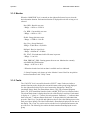
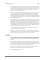
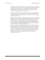
The RS422 and MIL-STD-188-114 interface also provides bi-directional relay loopback
of both the clock and data at the DCE interface. In LOOPBACK, from the DTE side, SD
is connected to RD, and either ST or TT (in INTERNAL or EXTERNAL mode) is
looped back to RT. From the modem side, the received data and recovered clock are
routed back to the modulator input for retransmission.
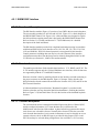
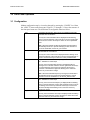
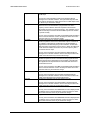
Loop timing is supported by the selection of jumper JP10. When in the ON position the
transmit clock (ST) is replaced by the clock recovered from the satellite (RT). Active
loop timing is indicated by a yellow light on the front edge of the card. The JP10 REM
setting is for future options.
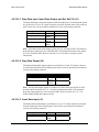
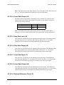
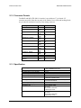
Three fault outputs are provided on dry contact Form C relays. These are the COMMON
EQUIPMENT, MODULATOR, and DEMODULATOR faults. They are available on the
FAULT connector on the modem rear panel. Generation of these fault conditions is
described in Section 3.1.5. Fault indicators are also provided on TTL open collector
drivers on the RS422 or MIL-STD-188-114 connector. The TTL MOD fault indicates a
MODULATOR fault or COMMON EQUIPMENT fault, while the TTL DEMOD fault
indicates a DEMOD or COMMON EQUIPMENT fault.
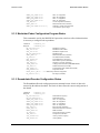
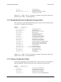
The printed circuit board for the RS422/MIL188-114 interface is used for a number of
different interface types. The differences will be jumper settings on the board as well as
hardware configuration. There will be different parts installed for the various different
configurations. Changing to a different interface can be done by replacing the board.
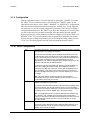
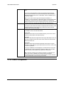
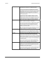
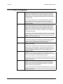
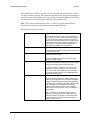
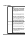
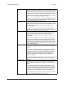
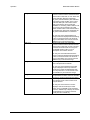
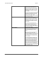
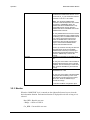
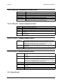
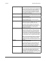
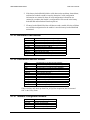
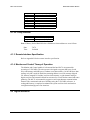
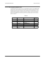
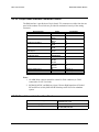
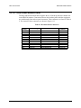
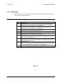
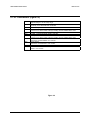
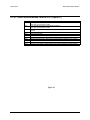
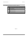
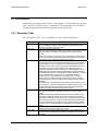
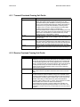
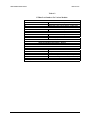
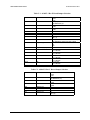
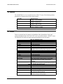
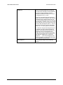
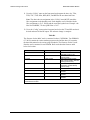
Table C-1 will describe the jumper settings for a Rev E board and Table C-2 describes
the jumper settings for a Rev C board. These jumpers are factory set for each given
configuration. You should not have to change them. This list is supplied for
troubleshooting purposes only.
C-C–12
MN/U-SDM309B Rev. #