1
Cisco AS5x00 Case Study for Basic
IP Modem Services
Corporate Headquarters
Cisco Systems, Inc.
170 West Tasman Drive
San Jose, CA 95134-1706
USA
http://www.cisco.com
Tel: 408 526-4000
800 553-NETS (6387)
Fax: 408 526-4100
Text Part Number: OL-0364-01
THE SPECIFICATIONS AND INFORMATION REGARDING THE PRODUCTS IN THIS MANUAL ARE SUBJECT TO CHANGE WITHOUT
NOTICE. ALL STATEMENTS, INFORMATION, AND RECOMMENDATIONS IN THIS MANUAL ARE BELIEVED TO BE ACCURATE BUT ARE
PRESENTED WITHOUT WARRANTY OF ANY KIND, EXPRESS OR IMPLIED. USERS MUST TAKE FULL RESPONSIBILITY FOR THEIR
APPLICATION OF ANY PRODUCTS.
THE SOFTWARE LICENSE AND LIMITED WARRANTY FOR THE ACCOMPANYING PRODUCT ARE SET FORTH IN THE INFORMATION
PACKET THAT SHIPPED WITH THE PRODUCT AND ARE INCORPORATED HEREIN BY THIS REFERENCE. IF YOU ARE UNABLE TO
LOCATE THE SOFTWARE LICENSE OR LIMITED WARRANTY, CONTACT YOUR CISCO REPRESENTATIVE FOR A COPY.
The following information is for FCC compliance of Class A devices: This equipment has been tested and found to comply with the limits for a Class A
digital device, pursuant to part 15 of the FCC rules. These limits are designed to provide reasonable protection against harmful interference when the
equipment is operated in a commercial environment. This equipment generates, uses, and can radiate radio-frequency energy and, if not installed and used
in accordance with the instruction manual, may cause harmful interference to radio communications. Operation of this equipment in a residential area is
likely to cause harmful interference, in which case users will be required to correct the interference at their own expense.
The following information is for FCC compliance of Class B devices: The equipment described in this manual generates and may radiate radio-frequency
energy. If it is not installed in accordance with Cisco’s installation instructions, it may cause interference with radio and television reception. This
equipment has been tested and found to comply with the limits for a Class B digital device in accordance with the specifications in part 15 of the FCC rules.
These specifications are designed to provide reasonable protection against such interference in a residential installation. However, there is no guarantee
that interference will not occur in a particular installation.
Modifying the equipment without Cisco’s written authorization may result in the equipment no longer complying with FCC requirements for Class A or
Class B digital devices. In that event, your right to use the equipment may be limited by FCC regulations, and you may be required to correct any
interference to radio or television communications at your own expense.
You can determine whether your equipment is causing interference by turning it off. If the interference stops, it was probably caused by the Cisco equipment
or one of its peripheral devices. If the equipment causes interference to radio or television reception, try to correct the interference by using one or more
of the following measures:
• Rotate the television or radio antenna until the interference stops.
• Move the equipment to one side or the other of the television or radio.
• Move the equipment farther away from the television or radio.
• Plug the equipment into an outlet that is on a different circuit from the television or radio. (That is, make certain the equipment and the television or radio
are on circuits controlled by different circuit breakers or fuses.)
Modifications to this product not authorized by Cisco Systems, Inc. could void the FCC approval and negate your authority to operate the product.
The Cisco implementation of TCP header compression is an adaptation of a program developed by the University of California, Berkeley (UCB) as part of
UCB’s public domain version of the UNIX operating system. All rights reserved. Copyright © 1981, Regents of the University of California.
NOTWITHSTANDING ANY OTHER WARRANTY HEREIN, ALL DOCUMENT FILES AND SOFTWARE OF THESE SUPPLIERS ARE PROVIDED
“AS IS” WITH ALL FAULTS. CISCO AND THE ABOVE-NAMED SUPPLIERS DISCLAIM ALL WARRANTIES, EXPRESSED OR IMPLIED,
INCLUDING, WITHOUT LIMITATION, THOSE OF MERCHANTABILITY, FITNESS FOR A PARTICULAR PURPOSE AND
NONINFRINGEMENT OR ARISING FROM A COURSE OF DEALING, USAGE, OR TRADE PRACTICE.
IN NO EVENT SHALL CISCO OR ITS SUPPLIERS BE LIABLE FOR ANY INDIRECT, SPECIAL, CONSEQUENTIAL, OR INCIDENTAL
DAMAGES, INCLUDING, WITHOUT LIMITATION, LOST PROFITS OR LOSS OR DAMAGE TO DATA ARISING OUT OF THE USE OR
INABILITY TO USE THIS MANUAL, EVEN IF CISCO OR ITS SUPPLIERS HAVE BEEN ADVISED OF THE POSSIBILITY OF SUCH DAMAGES.
Access Registrar, AccessPath, Any to Any, AtmDirector, CCDA, CCDE, CCDP, CCIE, CCNA, CCNP, CCSI, CD-PAC, the Cisco logo, Cisco Certified
Internetwork Expert logo, CiscoLink, the Cisco Management Connection logo, the Cisco NetWorks logo, the Cisco Powered Network logo, Cisco Systems Capital,
the Cisco Systems Capital logo, Cisco Systems Networking Academy, the Cisco Systems Networking Academy logo, the Cisco Technologies logo, ConnectWay,
Fast Step, FireRunner, GigaStack, IGX, Internet Quotient, Kernel Proxy, MGX, MultiPath Data, MultiPath Voice, Natural Network Viewer, NetSonar, Network
Registrar, Packet, PIX, Point and Click Internetworking, Policy Builder, Precept, Secure Script, ServiceWay, SlideCast, SMARTnet, The Cell, TrafficDirector,
TransPath, ViewRunner, Virtual Service Node, VisionWay, VlanDirector, WebViewer, Workgroup Director, and Workgroup Stack are trademarks; Changing the
Way We Work, Live, Play, and Learn, Empowering the Internet Generation, The Internet Economy, and The New Internet Economy are service marks; and ASIST,
BPX, Catalyst, Cisco, Cisco IOS, the Cisco IOS logo, Cisco Systems, the Cisco Systems logo, the Cisco Systems Cisco Press logo, Enterprise/Solver,
EtherChannel, EtherSwitch, FastHub, FastLink, FastPAD, FastSwitch, GeoTel, IOS, IP/TV, IPX, LightStream, LightSwitch, MICA, NetRanger, Post-Routing,
Pre-Routing, Registrar, StrataView Plus, Stratm, TeleRouter, and VCO are registered trademarks of Cisco Systems, Inc. or its affiliates in the U.S. and certain other
countries. All other trademarks mentioned in this document are the property of their respective owners. The use of the word partner does not imply a partnership
relationship between Cisco and any of its resellers. (9910R)
Cisco AS5x00 Case Study for Basic IP Modem Services
Copyright © 1999, Cisco Systems, Inc.
All rights reserved.
C O N T E N T S
SECTION
1
Network Design and Case Study Overview
Introduction
1-1
1-1
Scenario Description
1-1
Dial Planning Questionnaire
Network Service Definition
1-3
1-5
Network Topology, Hardware, and Software Selection
Configuration Design Parameters
1-8
Deployment and Operation Task Strategy
SECTION
2
1-12
Commissioning the Cisco AS5300 Hardware
In this Section
1-7
2-1
2-1
Understanding the Basic Hardware Architecture
Task 1. Verifying Basic Setup
2-1
2-3
1.1 Analyzing the System Boot Dialog
2-3
1.2 Checking the Initial Running-Config
2-6
1.3 Exploring the Cisco IOS File System
2-7
1.4 Investigating Memory Usage
1.5 Inspecting CPU Utilization
2-10
2-11
Task 2. Configuring Cisco IOS Basics
2-12
2.1 Configuring the Host Name, Enable Secret, and Time Stamps
2.2 Configuring Local AAA Security
2.3 Setting Up a Login Banner
2-12
2-13
2-14
2.4 Configuring the Loopback Interfaces, Ethernet Interface, and IP Route
2.5 Upgrading to a New Cisco IOS Release
Task 3. Enabling the T1 Controllers
2-16
2-18
Task 4. Configuring the Serial Interfaces
Task 5. Configuring Modems and Lines
Task 6. Enabling IP Basic Setup
2-22
2-24
2-26
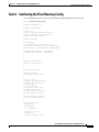
Task 7. Testing Asynchronous-Shell Connections
Task 8. Confirming the Final Running-Config
What to do Next
2-15
2-27
2-29
2-31
Cisco AS5x00 Case Study for Basic IP Modem Services
11/24/1999
v
Contents
SECTION
3
Commissioning the Cisco AS5800 Hardware
In this Section
3-1
3-1
Understanding the Basic Hardware Architecture
3-1
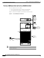
The Cisco 7206 Router Shelf and the Cisco DS5814 Dial Shelf
Call-Processing Components
Task 1. Verifying Basic Setup
3-2
3-3
3-5
1.1 Analyzing the System Boot Dialog
1.2 Matching the Cisco IOS Images
1.3 Inspecting the Dial Shelf
3-6
3-9
3-11
DSC Troubleshooting Tips
3-11
Feature Board Troubleshooting Tips
1.4 Understanding DSIP Commands
3-13
3-14
1.5 Checking the Initial Running-Config
3-16
1.6 Exploring the Cisco IOS File System
3-18
1.7 Investigating Memory Usage
1.8 Inspecting CPU Utilization
3-21
3-23
Task 2. Configuring Cisco IOS Basics
3-24
2.1 Configuring the Host Name, Enable Secret, and Time Stamps
2.2 Configuring Local AAA Security
2.3 Setting Up a Login Banner
2.4 Configuring Basic IP
3-25
3-26
3-27
Task 3. Enabling the T3/T1 Controllers
Task 4. Configuring the Serial Interfaces
Task 5. Configuring Modems and Lines
Task 6. Enabling IP Basic Setup
3-29
3-34
3-36
3-37
Task 7. Testing Asynchronous EXEC Shell Connections
Task 8. Confirming the Final Running-Config
What to do Next
vi
3-24
3-38
3-41
3-42
Cisco AS5x00 Case Study for Basic IP Modem Services
11/24/1999
Contents
SECTION
4
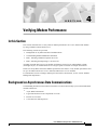
Verifying Modem Performance
In this Section
4-1
4-1
Background on Asynchronous Data Communications
Async DataComm Model
4-1
4-2
Logical Packet and Circuit Components of a NAS
RS-232 in Cisco IOS
4-4
Cisco IOS Line-Side Inspection
4-6
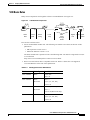
Understanding Modem Modulation Standards
V.34 Basic Rules
4-8
V.90 Basic Rules
4-9
4-8
Task 1. Initiating a Modem Loopback Test Call
4-10
Task 2. Initiating and Inspecting a V.90 Test Call
What to do Next
SECTION
5
4-18
4-26
Configuring PPP and Authentication
In this Section
4-3
5-1
5-1
Task 1. Configuring PPP Authentication for Local AAA
Task 2. Configuring IPCP Options
5-1
5-2
Task 3. Configuring LCP Options
5-3
Task 4. Enabling PPP Autoselect
5-4
Task 5. Testing Asynchronous PPP Connections
5.1 Successful PPP Negotiation Debug
5-5
5-5
5.2 Failed PPP Negotiation Debug and Troubleshooting
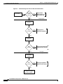
5.3 Troubleshooting Flow Diagrams
Task 6. Inspecting Active Call States
6.1 Show Caller Statistics
5-7
5-10
5-10
6.2 Fast Switching and Route Caching Statistics
Task 7. Confirming the Final Running-Config
What to do Next
5-7
5-12
5-13
5-13
Cisco AS5x00 Case Study for Basic IP Modem Services
11/24/1999
vii
Contents
SECTION
6
Modem Management Operations
In this Section
6-1
6-1
Task 1. Managing Modem Firmware
6-2
1.1 Inspecting Modem Firmware
6-2
1.2 Upgrading Modem Firmware
6-6
Task 2. Configuring Modems Using Modem Autoconfigure
2.1 Basic Rules for Modem Autoconfigure
6-11
2.2 Modem Autoconfigure K56Flex Example
Task 3. Gathering and Viewing Call Statistics
3.1 Using the Cisco IOS EXEC (CLI)
3.2 Using Modem Call-Record Terse
3.3 Using SNMP
What to do Next
SECTION
7
6-12
6-13
6-17
6-18
6-18
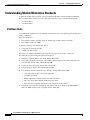
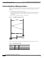
Understanding Network Management Basics
7-2
Task 1. Enabling the Network Time Protocol
7-3
Task 2. Enabling Syslog
7-4
Task 3. Enabling SNMP
7-6
Task 5. Confirming the Final Running-Config
What to do Next
8
7-1
7-1
Task 4. Disabling the Logging of Access Interfaces
SECTION
6-11
Enabling Management Protocols: NTP, SNMP, and Syslog
In this Section
6-10
7-9
7-10
7-13
Inspecting the Final Running Configuration for the Cisco AS5300 and AS5800
In this Section
8-1
8-1
Cisco AS5300 Configuration
8-1
Cisco AS5800 Configuration
8-4
INDEX
viii
Cisco AS5x00 Case Study for Basic IP Modem Services
11/24/1999
S E C T I O N
1
Network Design and Case Study Overview
Introduction
This case study describes how two companies set up basic modem IP services by using Cisco AS5x00
network access servers.
The two companies
Plan and design a basic IP modem dial-up network.
Deploy networking equipment by configuring, verifying, and troubleshooting the Cisco IOS.
Prepare for operations by inspecting modem call statistics and enabling basic management
protocols.
This case study
Note
Is for network engineers who work with dial-up access technologies.
Assumes that the reader has a CCNA or higher level of familiarity with Cisco IOS routers
and technologies.
The term Cisco AS5x00 refers to the Cisco AS5300 and AS5800 network access servers.
Although this case study uses two specific companies as examples and seems very specific
at times, the principles in this case study can be applied on a general level.
Scenario Description
The following two companies are used in the case study:
Maui Onions—A co-operative marketing and distribution company for onions grown in Maui.
The company is installing a dial-up service for their members and roaming sales force.
THEnet—A competitive Internet Service Provider (ISP) in Austin, Texas. The company is
providing dial-up services to household consumers and university students. THEnet’s users want to
send email and surf the Internet with a web browser.
Cisco AS5x00 Case Study for Basic IP Modem Services
11/24/1999
1-1
Section 1
Scenario Description
Network Design and Case Study Overview
Both companies
Enable remote modem users to access IP backbone resources through the public switched telephone
network (PSTN).
Build an access network foundation that scales to support larger dial implementations for the
future.
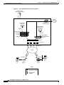
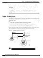
Have almost identical technology requirements and business applications. Therefore, one business
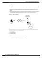
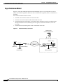
scenario diagram is shown for both companies. Figure 1-1 shows the business scenario.
Figure 1-1
Business Scenario
Headquarters
providing dial-up
services
PSTN
IP intranet
Internet
firewall
25672
Remote modem
users
Internet
This case study describes how to set up one network access server (NAS). Setting up the following
components is outside the scope of this document:
1-2
NAS stacking
AAA server setup
IP address scaling
Remote-node ISDN configuration (synchronous PPP)
Cisco AS5x00 Case Study for Basic IP Modem Services
11/24/1999
Section 1
Network Design and Case Study Overview
Dial Planning Questionnaire
Dial Planning Questionnaire
Both companies answer a planning questionnaire. Based on their design choices, both companies create
a network-service definition.
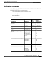
The dial questionnaire in Table 1-1 shows the following:
A series of planning design questions and configuration issues
A list of design options
Maui Onions’ design choices
THEnet’s design choices
Table 1-1
Dial Services Questionnaire
Design Questions
What is the user-growth projection for the
next 5 years.1
Design Options
Maui Onions
Design
Choices
THEnets
Design Choices
3 months
500 users
5,000 users
1 Year
1,000 users
20,000 users
5 Years
2,000 users
1 million users
15:1
10:1
What is the user-to-line ratio during busy
hours?
What access media is used for the dial
services?
Analog lines
Yes
Yes
ISDN BRI lines
No
No
What type of remote devices will be
supported?
Analog modems
Yes
Yes
Remote LANs
No
No
No
PCBUS ISDN
terminal adaptors
No
V.110
No
No
V.120
No
No
Windows 95
Yes
Yes
Windows 98
Yes
Yes
Windows NT
Yes
Yes
UNIX
No
Yes
MacOS
No
Yes
Will you support dial-in modem services?
Yes or No
Yes
Yes
Rank these technology priorities.
AAA design
#1
#2
IP design
#2
#3
V.90 modem
performance
#3
#1
What operating systems will be supported?
Cisco AS5x00 Case Study for Basic IP Modem Services
11/24/1999
1-3
Section 1
Dial Planning Questionnaire
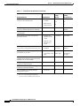
Table 1-1
Network Design and Case Study Overview
Dial Services Questionnaire (continued)
Design Questions
Design Options
Maui Onions
Design
Choices
THEnets
Design Choices
Yes
Yes
Yes
Yes
No
No
EXEC shell
sessions
PPP sessions
SLIP sessions
Will you support multilink? If yes, will you
scale to a stacked multi-chassis solution?
Yes or No
No
Yes. A stacked
solution.
Will you support PPP timeouts
(accounting)?
Yes or No
No
No
For the short term, where are the users’
passwords stored?
Local AAA
database in the
router
Local AAA
Local AAA
Remote AAA
database in a
server
In the long term, will you use a AAA
server? If yes, what protocol will you use?
TACACS+
Yes
Yes
RADIUS
TACACS+
RADIUS
Will users be allowed to change their own
passwords? If yes, how?
EXEC shell
Yes
Yes
CiscoSecure web EXEC shell
page
CiscoSecure
web page
Will the access network use an external
authentication database such as SecureID,
Windows NT, or Novell NDS?
Yes or No
Yes
No
Will you support per-user attribute
definitions (authorization)?
Yes or No
Yes
No
Do you have an existing accounting system
to monitor call-detail records?
Yes or No
No
Yes
Are you running an existing network
management system?
Yes or No
No
No
When users connect to modems, what
access service will they use?
1. Three months = current deployment requirement.
One year = current design plan requirement.
Five years = future scalability plan requirement.
1-4
Cisco AS5x00 Case Study for Basic IP Modem Services
11/24/1999
Section 1
Network Design and Case Study Overview
Network Service Definition
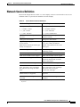
Network Service Definition
Based on the design choices in Table 1-1, each company creates its own network-to-user service
definition. Table 1-2 provides the definition for each company.
Table 1-2
User-to-Network Service Definitions
Maui Onions Requirements
THEnets Requirements
1
Line requirements for the next 5 years: Line requirements for the next 5 years:
3 months: 25 lines
3 months: 500 lines
1 year: 50 lines
1 year: 2000 lines
5 years: 100 lines
5 years: 100,000 lines
One Cisco AS5300 is required for the
first year.
One Cisco AS5800 is required for the
first three months.
Analog lines and modems.
Analog lines and modems.
Supported operating systems: Windows Supported operating systems: Windows
95, 98, NT, UNIX, and MacOS.
95, 98, and NT.
Maui Onions controls the client types
used by its employees.
THEnet offers Internet access to all
client types.
AAA is the highest technology priority. V.90 modem performance is the highest
technology priority.
Dial-in only support.
Dial-in only support.
EXEC shell and PPP session support.
EXEC shell and PPP session support.
No multilink PPP support.
Multilink PPP support in a stacked
solution for deployment in a future
phase of this project.
PPP timeouts will not be supported.
PPP timeouts will not be supported.
Remote AAA TACACS+ server to store
users’ passwords. Users can change
their passwords by using the EXEC
shell.
Remote AAA RADIUS server to store
users’ passwords. Users can change
their passwords by using the
Cisco Secure web page.
Per-user attribute definitions
(authorization) are supported.
Per-user attribute definitions are not
supported.
A network element management server
is needed.
A network element management server
is needed.
1. The line requirement is calculated by dividing the number of users by the user-to-line ratio during
busy hours.
Cisco AS5x00 Case Study for Basic IP Modem Services
11/24/1999
1-5
Section 1
Network Service Definition
Network Design and Case Study Overview
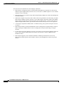
The network service definition for each company is different:
1-6
Maui Onions’ scaling projections are much smaller than THEnet’s projections. For this reason,
THEnet requires higher density network access servers (that is, THEnet requires a Cisco AS5800
instead of a Cisco AS5300).
Maui Onions cares more about security and less about billing. THEnet cares more about billing and
less about security.
THEnet has a higher V.90 priority and, for this reason, will spend more time fine tuning V.90 than
Maui Onions. THEnet’s primary objective is to get 56K modem-connections enabled. For THEnet,
higher connect speeds equate to increased sales, whereas Maui Onions’ revenue stream does not
depend on high modem-connect speeds. Maui Onions will use dial-up service for its employees.
AAA design is important to Maui Onions. A defined security policy protects enterprise network
resources.
Maui Onions enables its network administrator users to change their own passwords by using an
EXEC shell login. THEnet allows its users to change their own passwords using a web page
interface.
For the short term, both companies store users’ passwords in a local-username database inside the
router. In the long term, Maui Onions will scale to use TACACS+ security. THEnet will use
RADIUS security.
Maui Onions supports per-user attribute definitions. THEnet provides Internet access only.
Maui Onions enables specific onion vendors to dial in, pass through filters, and access specific
devices.
Cisco AS5x00 Case Study for Basic IP Modem Services
11/24/1999
Section 1
Network Design and Case Study Overview
Network Topology, Hardware, and Software Selection
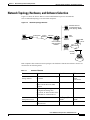
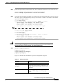
Network Topology, Hardware, and Software Selection
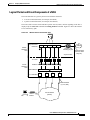
Figure 1-3 shows the devices that are used to build both dial-up access environments.
One recommended topology is used for both companies.
Figure 1-3
Network Topology Elements
Network element
management server
(NTP, Syslog, SNMP)
Analog lines
Clients
PSTN
AAA
server
PRI lines
Modems
DNS
server
Cisco AS5x00
with integrated
modems
IP intranet
Default
gateway
Internet
Both companies have similar network topologies. The hardware elements and software releases are
described in the following tables.
Table 1-1
Hardware Elements
Element
Purpose
Maui Onions
THEnet
Remote clients and
analog modems
To access the IP backbone through PCs
the PSTN.
PCs, Macs,
UNIX
workstations
Cisco AS5x00 NAS
To terminate modem calls and
Point-to-Point Protocol (PPP)
sessions.
Cisco AS5300
Cisco AS5800
PRI lines
To provide high throughput (64K)
for digital and analog calls.
T1 trunks
T3 trunks
In general, T1 and T3 trunks can be
ISDN PRIs or channelized T1s.
Network element
management server
To maintain and monitor the NAS.
NTP 1, syslog 2,
SNMP3
NTP, syslog,
SNMP
Remote AAA server
To perform basic user
authentication.
TACACS+
RADIUS
Cisco AS5x00 Case Study for Basic IP Modem Services
11/24/1999
1-7
24524
Internet
firewall
Section 1
Configuration Design Parameters
Table 1-1
Network Design and Case Study Overview
Hardware Elements (continued)
Element
Purpose
Maui Onions
THEnet
Default gateway
To forward packets to the IP
intranet and Internet.
Router
Router
Internet firewall
To protect the IP intranet from
intruders and hackers.
Cisco PIX
Cisco PIX
Edge router
To provide connectivity between
the access subnet and the IP
backbone.
Router
Router
1. Network Time Protocol
2. System logs (logging)
3. Simple Network Management Protocol
To obtain the latest Cisco IOS features and bug fixes, the access servers are upgraded to the following
software releases:
Table 1-2
Software Releases: Cisco IOS and MICA Portware
Hardware
Start with
Upgrade to
Cisco AS5300
Cisco IOS Release 11.3(7)AA
Cisco IOS Release 12.0(5)T
MICA portware 2.6.2.0
MICA portware 2.7.1.0
Cisco IOS Release 11.3(9)AA2
Cisco IOS Release 12.0(4)XL1
MICA portware 2.6.2.0
MICA portware 2.6.2.0 (same)
Cisco AS5800
Use a mature Cisco IOS release whenever possible. For example, a mature release is 12.0(10)T
not 12.0(1)T. Maintenance release 10 is more mature than maintenance release 1. During the
development of this document, the most mature releases available are 12.0(5)T and 12.0(4)XL1.
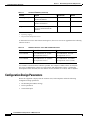
Configuration Design Parameters
Before the equipment is deployed at the customer sites, both companies define the following
configuration design parameters:
1-8
IP subnetting and address strategy
Device parameters
Network dial plan
Cisco AS5x00 Case Study for Basic IP Modem Services
11/24/1999
Section 1
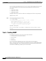
Network Design and Case Study Overview
Figure 1-4
Configuration Design Parameters
IP Subnetting Diagram
Hq-access
172.22.66.0/26
PSTN
NAS loopbacks
172.22.90.0/24
172.22.99.0/24
Clients
IP intranet
Modems
Internet
Note
This case study uses private RFC 1918 IP addresses. For more information, refer to the
following URL:
http://www.ietf.org/rfc/rfc1918.txt
For Maui Onions and THEnet, Table 1-5 through Table 1-7 describe the following:
IP subnetting plan
Device parameters
Dial plan
Table 1-5
IP Subnetting Plan
Network Name
Assigned Subnet
1
Description
Headquarters
Block
172.22.0.0/17
Remote block
172.22.128.0/17
The block of IP addresses reserved for the incoming
remote-node modem clients.
Hq-access
172.22.66.0/26
The headquarter’s access Ethernet subnet. All the access
devices are directly connected to this subnet.
The block of IP addresses reserved for the devices inside the
corporate network.
If additional access servers and POP-management devices are
needed, they are assigned to this IP subnet. This approach
simplifies network design.
Cisco AS5x00 Case Study for Basic IP Modem Services
11/24/1999
1-9
28312
Internet
firewall
Section 1
Configuration Design Parameters
Table 1-5
Network Design and Case Study Overview
IP Subnetting Plan
Network Name
Assigned Subnet
Description
NAS loopback 0
172.22.99.0/24
Identifies the router with a unique and stable IP address for
network management purposes. One IP address from a
common address block is assigned to each network device.
This technique enables the network operations center (NOC)
to more easily perform security filtering.
One class C subnet that used to identify devices can support
254 distinct nodes with unique loopback IP addresses.
NAS loopback 1
172.22.90.0/24
Used to host a pool of IP addresses for the remote nodes.
In this way, one route is summarized and propagated to the
backbone instead of 254 host routes.
Setting up interior gateway protocols (IGP) is outside the
scope of this document. For example, OSPF and EIGRP.
1. The /17 means there are 17 bits in the subnet mask. For /26, there are 26 bits in the subnet mask and so on.
Note
1-10
A simple IP address strategy is used for this case study. Scaling IP addresses is
outside the scope of this document.
Cisco AS5x00 Case Study for Basic IP Modem Services
11/24/1999
Section 1
Network Design and Case Study Overview
Table 1-6
Configuration Design Parameters
Device Parameters
Device
Parameters
Router host names
5300-NAS
5800-NAS
Interface ethernet 0
172.22.66.23 255.255.255.0
Interface loopback 0
172.22.99.1 255.255.255.255
Interface loopback 1
172.22.90.1 255.255.255.0
IP local address pool
5300-NAS = 172.22.90.2 through 172.22.90.97
5800-NAS = 172.22.90.2 through 172.22.90.254
Primary and secondary
name servers
172.22.11.10
172.22.12.11
Default gateway
172.22.66.1
IP domain names
mauionions.com
the.net
Network element
management server
172.22.66.18
(NTP, SNMP, syslog)
SNMP community
strings
Table 1-7
Read only (RO) = poptarts
Read write (RW) = pixysticks
Dial Plan
Item
Value
Description
PRI telephone
numbers
4085551234
4085556789
Telephone numbers assigned to the T1 trunks.
ISDN PRI
switch type
Framing type
Line code type
These numbers are used for:
5ESS
Testing new modem firmware
Isolating debugs for specific users
The telco’s switch type that connects to the
T1 PRI trunks. In this case study, the T1 trunks
are not using channel associated signaling
(CAS).
ESF is used for Maui
Onions’ T1 trunks.
M23 is used for THEnet’s
T3 trunk.
B8ZS is used for Maui
Onions’ T1 trunks.
No line code is used for
THEnet’s T3 trunk.
Defines the control bits and data bits.
An encoding method used to allow
synchronous data to be transmitted in a
compatible format.
Cisco AS5x00 Case Study for Basic IP Modem Services
11/24/1999
1-11
Section 1
Deployment and Operation Task Strategy
Table 1-7
Network Design and Case Study Overview
Dial Plan (continued)
Item
Value
Description
Test call login
username = dude
password = dude-pw
Username password for sending test calls into
the NAS.
Deployment and Operation Task Strategy
Table 1-8 describes the deployment and operation task strategy used in this case study. Maui Onions
and THEnet use a common strategy.
Table 1-8
Section
Task
2
Commissioning the Cisco AS5300
Hardware
3
4
5
6
1-12
Deployment and Operation Task Strategy
Commissioning the Cisco AS5800
Hardware
Verifying Modem Performance
Configuring PPP and Authentication
Modem Management Operations
Description
Understanding the Cisco AS5300 basic
hardware architecture.
Supporting EXEC terminal shell services
and login prompts for modem clients.
Understanding the Cisco AS5800 basic
hardware architecture.
Supporting EXEC terminal shell services
and login prompts for modem clients.
Understanding and troubleshooting basic
modem connectivity.
Optimizing modem connect speeds.
Configuring PPP authentication for
local AAA.
Configuring IP Control Protocol (IPCP)
options.
Configuring Link Control Protocol
(LCP) options.
Enabling PPP autoselect.
Testing asynchronous PPP connections.
Inspecting active call states.
Managing modem firmware.
Configuring modems by using modem
autoconfigure.
Gathering and viewing call statistics.
Cisco AS5x00 Case Study for Basic IP Modem Services
11/24/1999
Section 1
Network Design and Case Study Overview
Table 1-8
Deployment and Operation Task Strategy
Deployment and Operation Task Strategy (continued)
Section
Task
Description
7
Enabling Management Protocols: NTP,
SNMP, and Syslog
Enabling the following management
protocols as part of commissioning a dial
access service:
8
NTP
SNMP
Syslog
Inspecting the Final Running Configuration Referencing and editing full-function
for the Cisco AS5300 and AS5800
Cisco IOS NAS configurations.
Cisco AS5x00 Case Study for Basic IP Modem Services
11/24/1999
1-13
Deployment and Operation Task Strategy
1-14
Section 1
Network Design and Case Study Overview
Cisco AS5x00 Case Study for Basic IP Modem Services
11/24/1999
S E C T I O N
2
Commissioning the Cisco AS5300 Hardware
In this Section
This section describes how to configure Cisco AS5300 to support terminal EXEC shell services and
login prompts for client modems.
The following sub sections are provided:
Understanding the Basic Hardware Architecture
Task 1. Verifying Basic Setup
Task 2. Configuring Cisco IOS Basics
Task 3. Enabling the T1 Controllers
Task 4. Configuring the Serial Interfaces
Task 5. Configuring Modems and Lines
Task 6. Enabling IP Basic Setup
Task 7. Testing Asynchronous-Shell Connections
Task 8. Confirming the Final Running-Config
In this case study, Maui Onions commissions the Cisco AS5300. Local-based authentication is used.
After the Cisco AS5300 is commissioned, Maui Onions configures and tests PPP as described in the
section “Configuring PPP and Authentication.” In the future, Maui Onions will use a AAA TACACS+
server.
Note
For a description of terminal EXEC shell services, see the section “Task 7. Testing
Asynchronous-Shell Connections.”
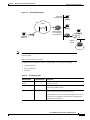
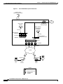
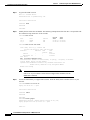
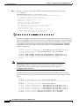
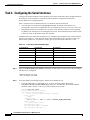
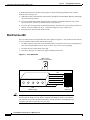
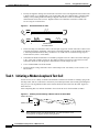
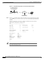
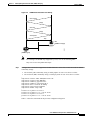
Understanding the Basic Hardware Architecture
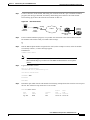
Figure 2-1 shows the logical and physical system architecture for the Cisco AS5300. It illustrates the
components used to process a call.
Cisco AS5x00 Case Study for Basic IP Modem Services
11/24/1999
2-1
Section 2
Understanding the Basic Hardware Architecture
Figure 2-1
Commissioning the Cisco AS5300 Hardware
Cisco AS5300 Basic System Architecture
Inside a Cisco
network access server
IP
network
Routing and
switching engine
Group-async
interface
Dialer interface
controlling the
D channels
Cloning
Asynchronous
interfaces
Cloning
TTY lines
Serial interface
channels S0:1, S0:2…
Modems
TDM bus
T1 controllers
PRI lines
PSTN
POTS line
Client
PC
BRI line
Client
modem
ISDN
router
Client
PC
Legend
= Synchronous PPP
= Configuration
template
2-2
29655
= Asynchronous PPP
Cisco AS5x00 Case Study for Basic IP Modem Services
11/24/1999
Section 2
Commissioning the Cisco AS5300 Hardware
Verifying Basic Setup
Figure 2-1 shows the following:
Client modems and ISDN routers dial into the access server through the PSTN.
Analog PPP calls connect to modems inside the access server.
Each modem inside the access server provides a corresponding TTY line and asynchronous
interface for terminating character and packet mode services.
Asynchronous interfaces clone their configurations from a group-async interface.
Synchronous PPP calls connect to serial interface channels (for example, S0:1 and S0:2).
Synchronous interfaces clone their configurations from a dialer interface.
One analog PPP call consumes:
One T1 DS0 channel
One channel in a TDM bus
One integrated modem
One TTY line
One asynchronous interface
One synchronous PPP call consumes:
One T1 DS0 channel
One serial interface channel
Task 1. Verifying Basic Setup
The following subsections detail the tasks required to verify that basic system components are
functioning normally:
1.1 Analyzing the System Boot Dialog
1.2 Checking the Initial Running-Config
1.3 Exploring the Cisco IOS File System
1.4 Investigating Memory Usage
1.5 Inspecting CPU Utilization
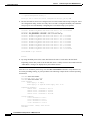
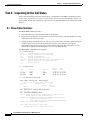
1.1 Analyzing the System Boot Dialog
The Cisco AS5300 has a specific boot sequence. To view the boot sequence through a terminal session,
you must have a console connection to the access server before it powers up.
The following boot sequence occurs. Event numbers and comments are inserted in the example to
describe the boot sequence.
System Bootstrap, Version 11.2(9)XA, RELEASE SOFTWARE (fc2)
Copyright (c) 1997 by cisco Systems, Inc.
AS5300 platform with 65536 Kbytes of main memory
program load complete, entry point: 0x80008000, size: 0xf5914
Self decompressing the image : #################################################
## [OK]
Notice: NVRAM invalid, possibly due to write erase.
Cisco AS5x00 Case Study for Basic IP Modem Services
11/24/1999
2-3
Section 2
Verifying Basic Setup
Commissioning the Cisco AS5300 Hardware
program load complete, entry point: 0x80008000, size: 0x45497c
Self decompressing the image : #################################################
################################################################################
################################################################################
################################################################################
################################################################################
################################################################################
##################### [OK]
Event 1—In the previous segment, the NAS decompresses the system boot image, tests the NVRAM
for validity, and decompresses the Cisco IOS image.
Restricted Rights Legend
Use, duplication, or disclosure by the Government is
subject to restrictions as set forth in subparagraph
(c) of the Commercial Computer Software - Restricted
Rights clause at FAR sec. 52.227-19 and subparagraph
(c) (1) (ii) of the Rights in Technical Data and Computer
Software clause at DFARS sec. 252.227-7013.
cisco Systems, Inc.
170 West Tasman Drive
San Jose, California 95134-1706
Cisco Internetwork Operating System Software
IOS (tm) 5300 Software (C5300-IS-M), Version 11.3(7)AA, EARLY DEPLOYMENT MAINTENANCE
RELEASE SOFTWARE ()
Copyright (c) 1986-1999 by cisco Systems, Inc.
Compiled Fri 08-Jan-99 13:43 by jjgreen
Image text-base: 0x60008920, data-base: 0x60788000
cisco AS5300 (R4K) processor (revision A.32) with 65536K/16384K bytes of memory.
Processor board ID 11811596
R4700 processor, Implementation 33, Revision 1.0 (512KB Level 2 Cache)
Bridging software.
X.25 software, Version 3.0.0.
SuperLAT software copyright 1990 by Meridian Technology Corp).
Primary Rate ISDN software, Version 1.1.
Backplane revision 2
Manufacture Cookie Info:
EEPROM Type 0x0001, EEPROM Version 0x01, Board ID 0x30,
Board Hardware Version 1.64, Item Number 800-2544-2,
Board Revision B0, Serial Number 11811596,
PLD/ISP Version 0.0, Manufacture Date 9-Dec-1998.
1 Ethernet/IEEE 802.3 interface(s)
1 FastEthernet/IEEE 802.3 interface(s)
96 terminal line(s)
4 Channelized T1/PRI port(s)
128K bytes of non-volatile configuration memory.
16384K bytes of processor board System flash (Read/Write)
8192K bytes of processor board Boot flash (Read/Write)
Event 2—The following components are detected: Cisco IOS Release, available memory, hardware
interfaces, and modem lines.
If a hardware card is not recognized, verify that you are running the optimum version of Cisco IOS.
Refer to the Hardware-Software Compatibility Matrix at the following URL:
2-4
Cisco AS5x00 Case Study for Basic IP Modem Services
11/24/1999
Section 2
Commissioning the Cisco AS5300 Hardware
Verifying Basic Setup
http://cco-sj-1.cisco.com/cgi-bin/front.x/Support/HWSWmatrix/hwswmatrix.cgi
--- System Configuration Dialog --Would you like to enter the initial configuration dialog? [yes/no]: no
Event 3—Because the NAS has never been configured, the NAS cannot find a startup-config file.
Therefore, the software asks, “Would you like to enter the initial configuration dialog? [yes/no]:”
Enter no. In this document, the Cisco IOS is configured manually. The automatic setup script is not
used. Configuring the Cisco IOS manually develops your expertise.
00:00:18:
00:00:18:
00:00:19:
00:00:19:
00:00:43:
00:00:43:
00:00:44:
00:00:46:
%LINK-3-UPDOWN: Interface Ethernet0, changed state to up
%LINK-3-UPDOWN: Interface FastEthernet0, changed state to up
%LINEPROTO-5-UPDOWN: Line protocol on Interface Ethernet0, changed stp
%LINEPROTO-5-UPDOWN: Line protocol on Interface FastEthernet0, changen
%LINK-5-CHANGED: Interface Ethernet0, changed state to administrativen
%LINK-5-CHANGED: Interface FastEthernet0, changed state to administran
%LINEPROTO-5-UPDOWN: Line protocol on Interface Ethernet0, changedn
%SYS-5-RESTART: System restarted --
00:01:07: %MICA-5-BOARDWARE_RUNNING: Slot 1 is running boardware version 1.3.7.0
00:01:07: %MICA-5-BOARDWARE_RUNNING: Slot 2 is running boardware version 1.3.7.0
Press RETURN to get started!
Router>
Event 4—The state of the LAN interfaces is displayed, and the MICA modem boardware version is
detected (version 1.3.7.0). The Cisco AS5300 can be fitted with MICA or Microcom modems.
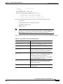
Enter the show version command to check the system hardware, Cisco IOS image name, uptime, and
restart reason:
Router>enable
Router#show version
Cisco Internetwork Operating System Software
IOS (tm) 5300 Software (C5300-IS-M), Version 11.3(7)AA, EARLY DEPLOYMENT MAINTENANCE
RELEASE SOFTWARE ()
Copyright (c) 1986-1999 by cisco Systems, Inc.
Compiled Fri 08-Jan-99 13:43 by jjgreen
Image text-base: 0x60008920, data-base: 0x60788000
ROM: System Bootstrap, Version 11.2(9)XA, RELEASE SOFTWARE (fc2)
BOOTFLASH: 5300 Software (C5300-BOOT-M), Version 11.2(9)XA1,
Router uptime is 9 minutes
System restarted by power-on at 16:59:44 PST Fri Dec 31 1999
System image file is "flash:c5300-is-mz.113-7.AA"
cisco AS5300 (R4K) processor (revision A.32) with 65536K/16384K bytes of memory.
Processor board ID 11811596
R4700 processor, Implementation 33, Revision 1.0 (512KB Level 2 Cache)
Bridging software.
X.25 software, Version 3.0.0.
SuperLAT software copyright 1990 by Meridian Technology Corp).
Cisco AS5x00 Case Study for Basic IP Modem Services
11/24/1999
2-5
Section 2
Verifying Basic Setup
Commissioning the Cisco AS5300 Hardware
Primary Rate ISDN software, Version 1.1.
Backplane revision 2
Manufacture Cookie Info:
EEPROM Type 0x0001, EEPROM Version 0x01, Board ID 0x30,
Board Hardware Version 1.64, Item Number 800-2544-2,
Board Revision B0, Serial Number 11811596,
PLD/ISP Version 0.0, Manufacture Date 9-Dec-1998.
1 Ethernet/IEEE 802.3 interface(s)
1 FastEthernet/IEEE 802.3 interface(s)
96 terminal line(s)
4 Channelized T1/PRI port(s)
128K bytes of non-volatile configuration memory.
16384K bytes of processor board System flash (Read/Write)
8192K bytes of processor board Boot flash (Read/Write)
Configuration register is 0x2102
Table 2-1 describes the significant output fields in the previous example:
Table 2-1
Show Version Command Field Descriptions
Field
Description
Router uptime is 9 minutes
Watch for unscheduled reloads by inspecting
this field.
System restarted by power-on at
16:59:44 PST Fri Dec 31 1999
Tells you why the access server last reloaded.
If the field displays “power-on,” a power
interruption caused the reload.
System image file is
"flash:c5300-is-mz.113-7.AA"
The Cisco AS5300 booted from this image
location.
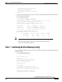
1.2 Checking the Initial Running-Config
The Cisco IOS creates an initial running configuration. Inspect the configuration to get familiar with
the default settings.
Router>enable
Router#show running-config
Building configuration...
Current configuration:
!
version 11.3
service timestamps debug uptime
service timestamps log uptime
no service password-encryption
!
hostname Router
!
controller T1 0
clock source line primary
!
controller T1 1
clock source line secondary
2-6
Cisco AS5x00 Case Study for Basic IP Modem Services
11/24/1999
Section 2
Commissioning the Cisco AS5300 Hardware
Verifying Basic Setup
!
controller T1 2
clock source internal
!
controller T1 3
clock source internal
!
interface Ethernet0
no ip address
shutdown
!
interface FastEthernet0
no ip address
shutdown
!
ip classless
!
line con 0
transport input none
line 1 96
line aux 0
line vty 0 4
!
end
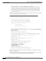
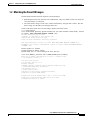
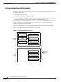
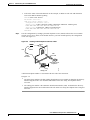
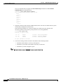
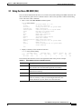
1.3 Exploring the Cisco IOS File System
Get familiar with the file system and memory storage areas. The Cisco IOS File System (IFS) feature
provides a single interface to:
The Flash memory file system
The network file system (TFTP, rcp, and FTP)
Any other endpoint for reading or writing data (such as NVRAM, modem firmware, the running
configuration, ROM, raw system memory, Xmodem, and Flash load helper log).
IFS first appeared in Cisco IOS Releases 11.3 AA and 12.0. For more information about IFS, refer to
the chapter Using the Cisco IOS File System in the Release 12.0 Configuration Fundamentals
Configuration Guide at the following URL:
http://www.cisco.com/univercd/cc/td/doc/product/software/ios120/12cgcr/fun_c/fcprt2/fcifs.htm
Cisco AS5x00 Case Study for Basic IP Modem Services
11/24/1999
2-7
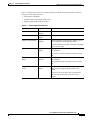
Section 2
Verifying Basic Setup
Commissioning the Cisco AS5300 Hardware
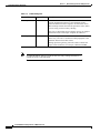
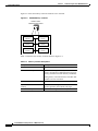
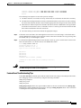
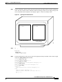
Figure 2-2 shows the memory locations inside the Cisco AS5300.
Figure 2-2
AS5300 Memory Locations
CPU
(R4700)
System Flash
memory
Processor
memory
Boot Flash
memory
Pocket I/O
memory
NVRAM
memory
23817
Inside a Cisco
network access server
Table 2-2 describes the memory locations shown in Figure 2-2.
Table 2-2
Memory Location Descriptions
Component
Description
R4700 CPU
RISC 4700 central processing unit.
Processor memory
The Cisco IOS image is initially read out of Flash
memory, decompressed, and loaded into processor
memory (also known as main memory or DRAM).
Routing tables, call control blocks, and other data
structures are also stored here.
2-8
Packet I/O memory
Packets are temporarily stored in I/O memory.
System Flash and Boot Flash
memory
Stores Cisco IOS images, modem
firmware/portware, and custom web pages.
NVRAM memory
Non-volatile configuration memory.
Cisco AS5x00 Case Study for Basic IP Modem Services
11/24/1999
Section 2
Commissioning the Cisco AS5300 Hardware
Verifying Basic Setup
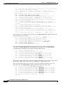
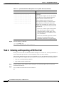
To inspect the file system, enter the show file systems command and dir comand as shown in the
following bullet list:
View the different file storage areas and file management functions:
Router#show file systems
File Systems:
Size(b)
16777216
8388608
126968
-
*
Free(b)
12236072
7382416
126968
-
Type
opaque
opaque
opaque
network
flash
flash
nvram
opaque
network
network
Flags
wo
rw
rw
rw
rw
rw
rw
wo
rw
rw
Prefixes
modem:
null:
system:
tftp:
flash:
bootflash:
nvram:
lex:
rcp:
ftp:
In addition, verify that you have everything that you ordered (for example, 16 MB of Flash
memory). The asterisk (*) indicates the current directory.
Display the objects in the system memory directory:
5300-NAS#dir system:
Directory of system:/
2
1
13
Note
dr-x
-rwdr-x
0
4492
0
<no date>
<no date>
<no date>
memory
running-config
ucode
Remember to include the trailing colon (:) in dir commands.
Inspect the contents of boot Flash:
Router#dir bootflash:
Directory of bootflash:/
1
-rw-
1006128
<no date>
c5300-boot-mz.112-9.XA1
8388608 bytes total (7382416 bytes free)
In the example, the boot image is c5300-boot-mz.112-9.XA1. The compressed file size is
1,006,128 bytes. The total boot Flash memory size is 8,388,608 bytes. The number of free bytes
is 7,382,416.
Display the contents of Flash memory:
Router#pwd
flash:
Router#dir:
Directory of flash:/
1
-rw-
4541080
<no date>
c5300-is-mz.113-7.AA
16777216 bytes total (12236072 bytes free)
The Cisco IOS image named c5300-is-mz.113-7.AA is present.
Cisco AS5x00 Case Study for Basic IP Modem Services
11/24/1999
2-9
Section 2
Verifying Basic Setup
Commissioning the Cisco AS5300 Hardware
Inspect the NVRAM directory:
Router#dir nvram:
Directory of nvram:/
1
2
-rw----
0
0
<no date>
<no date>
startup-config
private-config
126968 bytes total (126968 bytes free)
In the example, two files are present: startup-config and private-config. The private-config is a
secure file that is part of the startup configuration. It supports encryption technologies, but it is
not user accessible.
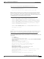
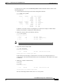
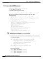
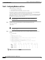
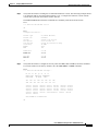
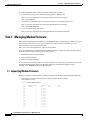
1.4 Investigating Memory Usage
Use the show memory summary command to:
Understand how memory is used for different processor and I/O memory processes
Identify memory fragmentation and memory leaks.
` Memory leak —Memory that is not released back to the processor. Memory leaks are indicated
by steady decreases of free memory. However, the preferred way to track memory leaks is to
monitor the FreeMem variable in the OID MIB.
` Memory fragmentation—Indicated by the largest block of memory not being equal to the
lowest block. Fragmentation increases as the numbers grow further apart.
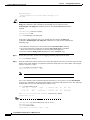
Processor and I/O Memory Usage
Total = Used
memory
memory
Router#show memory summary
Head Total(b)
Processor 60BA41A0 54902368
I/O 40000000 16777216
Note
2-10
Used(b)
3290524
2252584
+
Free
memory
Free(b) Lowest(b) Largest(b)
51611844 51459700 51470956
14524632 14524632 14524632
24515
Figure 2-3
Do not enter the show memory summary command with the terminal length 0 command
enabled. If you do, many screens of output will appear. It might interrupt your session.
Cisco AS5x00 Case Study for Basic IP Modem Services
11/24/1999
Section 2
Commissioning the Cisco AS5300 Hardware
Verifying Basic Setup
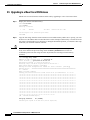
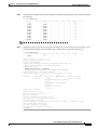
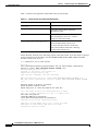
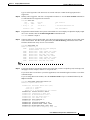
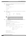
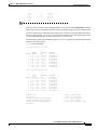
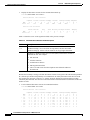
1.5 Inspecting CPU Utilization
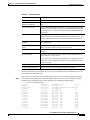
Enter the show processes cpu command to investigate high CPU utilization. High utilization causes
network performance problems. For example, knowing when the router is running at over 50%
utilization is critical. The router might start dropping packets if an unexpected traffic burst comes
through or if OSPF gets recalculated. Fast switching reduces CPU utilization.
Router#show processes cpu
CPU utilization for five seconds: 1%/0%; one minute: 0%; five minutes: 0%
PID Runtime(ms) Invoked uSecs
5Sec
1Min
5Min TTY Process
1
0
18973
0
0.00% 0.00% 0.00%
0 Load Meter
2
44
122
360
0.57% 0.06% 0.01% 98 Virtual Exec
3
70388
12820
5490
0.00% 0.04% 0.05%
0 Check heaps
4
0
2
0
0.00% 0.00% 0.00%
0 Pool Manager
5
0
2
0
0.00% 0.00% 0.00%
0 Timers
6
0
2
0
0.00% 0.00% 0.00%
0 Serial Backgroun
7
68
1876
36
0.00% 0.00% 0.00%
0 ARP Input
8
8
22758
0
0.00% 0.00% 0.00%
0 HC Counter Timer
9
0
2
0
0.00% 0.00% 0.00%
0 DDR Timers
10
0
2
0
0.00% 0.00% 0.00%
0 Dialer event
11
4
2
2000
0.00% 0.00% 0.00%
0 Entity MIB API
12
0
1
0
0.00% 0.00% 0.00%
0 SERIAL A'detect
13
0
4
0
0.00% 0.00% 0.00%
0 Critical Bkgnd
14
3396
165554
20
0.00% 0.00% 0.00%
0 Net Background
15
8
43
186
0.00% 0.00% 0.00%
0 Logger
16
377776
94479
3998
0.40% 0.23% 0.24%
0 TTY Background
17
4
94488
0
0.00% 0.00% 0.00%
0 Per-Second Jobs
18
0
47432
0
0.00% 0.00% 0.00%
0 CSM periodical p
19
0
47435
0
0.00% 0.00% 0.00%
0 CSM timer proces
20
0
2
0
0.00% 0.00% 0.00%
0 CSM Tone process
21
0
6
0
0.00% 0.00% 0.00%
0 Call Management
...
Snip
Look at the top line of the output. If you see high utilization numbers, for example over 50%, inspect
the columns 5Sec, 1Min, and 5Min. Find the process that uses the most CPU power. For an idle chassis,
numbers larger than two percent indicate a problem.
Cisco AS5x00 Case Study for Basic IP Modem Services
11/24/1999
2-11
Section 2
Configuring Cisco IOS Basics
Commissioning the Cisco AS5300 Hardware
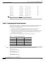
Task 2. Configuring Cisco IOS Basics
The following subsections detail the tasks required to apply a basic-running configuration to the NAS:
Tech Tip
2.1 Configuring the Host Name, Enable Secret, and Time Stamps
2.2 Configuring Local AAA Security
2.3 Setting Up a Login Banner
2.4 Configuring the Loopback Interfaces, Ethernet Interface, and IP Route
2.5 Upgrading to a New Cisco IOS Release
Periodically save the configuration by using the copy running-config startup-config
command.
2.1 Configuring the Host Name, Enable Secret, and Time Stamps
Assign a host name to the NAS, specify an enable secret password, and turn on time stamps:
Step 1
A host name allows you to distinguish between different network devices.
Enable secret passwords allow you to prevent unauthorized configuration changes.
Encrypted passwords in the configuration file adds greater security to the NAS.
Time stamps help you trace debug output for testing connections. Not knowing exactly when an
event occurs hinders you from examining background processes.
Enter the following commands in global configuration mode:
hostname 5300-NAS
enable secret 0 yourpasswordhere
service password-encryption
service timestamps debug datetime msec
service timestamps log datetime msec
Note
Step 2
The enable password command is an obsolete command. Do not use it.
Log in with the enable secret password. The show privilege command shows the current security
privilege level.
5300-NAS#disable
5300-NAS>enable
Password:
5300-NAS#show privilege
Current privilege level is 15
5300-NAS#
2-12
Cisco AS5x00 Case Study for Basic IP Modem Services
11/24/1999
Section 2
Commissioning the Cisco AS5300 Hardware
Configuring Cisco IOS Basics
2.2 Configuring Local AAA Security
Configure authentication, authorization, and accounting (AAA) to perform login authentication by
using the local username database. The login keyword authenticates EXEC shell users. Additionally,
configure PPP authentication to use the local database if the session was not already authenticated by
login.
AAA (called triple A) is the Cisco IOS security model used on all Cisco devices. AAA provides the
primary framework through which you set up access control on the NAS.
In this basic case study, the same authentication method is used on all interfaces. AAA is set up to use
the local database configured on the NAS. This local database is created with the username
configuration commands.
Step 1
Create a local login username database in global configuration mode. In this example,
the administrator’s username is admin. The remote client’s login username is dude.
!
username admin password adminpasshere
username dude password dudepasshere
!
Warning
Step 2
This step also prevents you from getting locked out of the NAS. If you get locked out, you
must reboot the device and perform password recovery.
Configure local AAA security in global configuration mode. You must enter the aaa new-model
command before the other two authentication commands.
!
aaa new-model
aaa authentication login default local
aaa authentication ppp default if-needed local
!
The following table describes the previous configuration snippet.
Table 2-3
Local AAA Commands
Command
Purpose
aaa new-model
Initiates the AAA access control system.
This command immediately locks down
login and PPP authentication.
aaa authentication login default local
Configures AAA to perform login
authentication by using the local username
database. The login keyword authenticates
EXEC shell users.
aaa authentication ppp default if-needed local
Configures PPP authentication to use the
local database if the session was not already
authenticated by login.
Cisco AS5x00 Case Study for Basic IP Modem Services
11/24/1999
2-13
Configuring Cisco IOS Basics
Step 3
Section 2
Commissioning the Cisco AS5300 Hardware
Log in with your username and password:
5300-NAS#login
User Access Verification
Username:admin
Password:
5300-NAS#
Successfully logging in means that your local username will work on any TTY or VTY line. Do not
disconnect your session until you can log in.
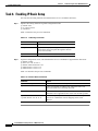
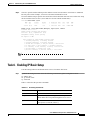
2.3 Setting Up a Login Banner
Create a login banner. A banner shows you which unit you are connected to (or are connecting through,
in the case of a console server).
Step 1
Create the banner:
5300-NAS(config)#banner login |
Enter TEXT message. End with the character '|'.
This is a secured device.
Unauthorized use is prohibited by law.
|
5300-NAS(config)#^Z
5300-NAS#
Step 2
Test the banner:
5300-NAS#login
This is a secured device.
Unauthorized use is prohibited by law.
User Access Verification
Username:admin
Password:
5300-NAS#
2-14
Cisco AS5x00 Case Study for Basic IP Modem Services
11/24/1999
Section 2
Commissioning the Cisco AS5300 Hardware
Configuring Cisco IOS Basics
2.4 Configuring the Loopback Interfaces, Ethernet Interface, and IP Route
To commission a basic dial access service:
Step 1
Create two loopback interfaces
Bring up the ethernet interface
Add an IP route to the default gateway
Assign the IP addresses, and create an IP route to the default gateway:
!
interface Loopback0
ip address 172.22.99.1 255.255.255.255
!
interface Loopback1
ip address 172.22.90.1 255.255.255.0
!
interface Ethernet0
ip address 172.22.66.23 255.255.255.0
!
ip route 0.0.0.0 0.0.0.0 172.22.66.1
!
In this example:
Step 2
Interface loopback 0—Identifies with a unique and stable IP address. One unique IP address from
a common block of addresses is assigned to each device in the IP network. This technique makes
security-filtering easy for the network operations center (NOC). One class C subnet used for device
identification can support 254 distinct devices with unique loopback addresses.
Interface loopback 1—Hosts a pool of IP addresses for the remote nodes. In this way, one route is
summarized and propagated to the backbone instead of 254 routes.
Verify that the Ethernet interface is up. Ping the default gateway to verify this.
5300-NAS#ping 172.22.66.1
Type escape sequence to abort.
Sending 5, 100-byte ICMP Echos to 172.22.66.1, timeout is 2 seconds:
.!!!!
Success rate is 80 percent (4/5), round-trip min/avg/max = 1/1/1 ms
5300-NAS#
This step verifies that you have IP connectivity with another device on the subnet. If the ping succeeds
to the default gateway, try pinging the DNS server in your backbone. Make sure the backbone routers
are configured to get to the access server; otherwise, the ping will not work. Configure the backbone
routers to support the routes to the networks you are using.
Note
An 80% ping-success rate is normal for the first time you ping an external device.
The NAS does not yet have an ARP entry (address resolution protocol) for the
external device. A 100% success rate is achieved the next time you ping the
device.
Cisco AS5x00 Case Study for Basic IP Modem Services
11/24/1999
2-15
Section 2
Configuring Cisco IOS Basics
Commissioning the Cisco AS5300 Hardware
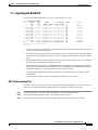
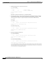
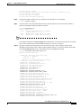
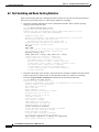
2.5 Upgrading to a New Cisco IOS Release
Obtain new Cisco IOS features and more stable code by upgrading to a new Cisco IOS release.
Step 1
Display the contents of Flash memory:
5300-NAS#cd flash:
5300-NAS#dir
Directory of flash:/
1
-rw-
4541080
<no date>
c5300-is-mz.113-7.AA
16777216 bytes total (12236072 bytes free)
5300-NAS#
Step 2
Timesaver
Copy the new image from the remote TFTP server into Flash memory. Make sure to specify your own
TFTP server’s IP address and Cisco IOS file name. In this example, Flash memory is erased before the
new image is downloaded. To see the bangs (!) during the download operation, you must have line wrap
enabled in your terminal emulation software.
Leave both images in Flash memory if you have the available space. If needed, you can
easily revert back to the previous image. Enter the boot system flash newiosname.bin
command to point to the new image file name. By default, the first image in Flash memory
is loaded.
5300-NAS#copy tftp: flash:
Address or name of remote host []? 172.22.66.18
Source filename []? goon/c5300-is-mz.120-5.T
Destination filename []? c5300-is-mz.120-5.T
Accessing tftp://172.22.66.18/goon/c5300-is-mz.120-5.T...
Erase flash: before copying? [confirm]y
Erasing the flash filesystem will remove all files! Continue? [confirm]y
Erasing device... eeeeeeeeeeeeeeeeeeeeeeeeeeeeeeeeeeeeeeeeeeeeeeeeeeeeeeeeeeeeee
ee ...erased
Erase of flash: complete
Loading goon/c5300-is-mz.120-5.T from 172.22.66.18 (via Ethernet0): !!!!!!!!!!
!!!!!!!!!!!!!!!!!!!!!!!!!!!!!!!!!!!!!!!!!!!!!!!!!!!!!!!!!!!!!!!!!!!!!!!!!!!!!!!!
!!!!!!!!!!!!!!!!!!!!!!!!!!!!!!!!!!!!!!!!!!!!!!!!!!!!!!!!!!!!!!!!!!!!!!!!!!!!!!!!
!!!!!!!!!!!!!!!!!!!!!!!!!!!!!!!!!!!!!!!!!!!!!!!!!!!!!!!!!!!!!!!!!!!!!!!!!!!!!!!!
!!!!!!!!!!!!!!!!!!!!!!!!!!!!!!!!!!!!!!!!!!!!!!!!!!!!!!!!!!!!!!!!!!!!!!!!!!!!!!!!
!!!!!!!!!!!!!!!!!!!!!!!!!!!!!!!!!!!!!!!!!!!!!!!!!!!!!!!!!!!!!!!!!!!!!!!!!!!!!!!!
!!!!!!!!!!!!!!!!!!!!!!!!!!!!!!!!!!!!!!!!!!!!!!!!!!!!!!!!!!!!!!!!!!!!!!!!!!!!!!!!
!!!!!!!!!!!!!!!!!!!!!!!!!!!!!!!!!!!!!!!!!!!!!!!!!!!!!!!!!!!!!!!!!!!!!!!!!!!!!!!!
!!!!!!!!!!!!!!!!!!!!!!!!!!!!!!!!!!!!!!!!!!!!!!!!!!!!!!!!!!!!!!!!!!!!!!!!!!!!!!!!
!!!!!!!!!!!!!!!!!!!!!!!!!!!!!!!!!!!!!!!!!!!!!!!!!!!!!!!!!!!!!!!!!!!!!!!!!!!!!!!!
!!!!!!!!!!!!!!!!!!!!!!!!!!!!!!!!!!!!!!!!!!!!!!!!!!!!!!!!!!!!!!!!!!!!!!!!!!!!!!!!
!!!!!!!!!!!!!!!!!!!!!!!!!!!!!!!!!!!!!!!!!!!!!!!!!!!!!!!!!!!!!!!!!!!!!!!!!!!!!!!!
!!!!!!!!!!!!!!!!!!!!!!!!!!!!!!!!!!!!!!!!!!!!!!!!!!!!!!!!!!!!!!!!!!!!!!!!!!!!!!!!
!!!!!!!!!!!!!!!!!!!!!!!!!!!!!!!!!!!!!!!!!!!!!!!!!!!!!!!!!!!!!!!!!!!!!!!!!!!!!!!!
!!!!!!!!!!!!!!!!!!!!!!!!!!!!!!!!!!!!!!!!!!!!!!!!!!!
[OK - 5633184/11266048 bytes]
Verifying checksum... OK (0x1AAF)
5633184 bytes copied in 30.480 secs (187772 bytes/sec)
2-16
Cisco AS5x00 Case Study for Basic IP Modem Services
11/24/1999
Section 2
Commissioning the Cisco AS5300 Hardware
Warning
Step 3
Configuring Cisco IOS Basics
Occasionally TFTP errors will occur. Make sure the verifying checksum reports OK.
Do not reload the access server if the checksum reports errors.
Verify that the old image was erased and the new image was downloaded. In this example, notice that
the 12.0(5)T image is larger than the old 11.3(7)AA image.
5300-NAS#dir flash:
Directory of flash:/
1
-rw-
5633184
<no date>
c5300-is-mz.120-5.T
16777216 bytes total (11143968 bytes free)
Step 4
Reload the NAS to run the new image. If you erased the old Cisco IOS image, make sure the
boot system flash oldiosname.bin command is not enabled and pointing to the old image file name.
Otherwise, the NAS will get stuck trying to reload the old image over and over again.
5300-NAS#reload
Proceed with reload? [confirm]
*Jan 1 04:50:32.814: %SYS-5-RELOAD:
System Bootstrap, Version 11.2(9)XA,
Copyright (c) 1997 by cisco Systems,
AS5300 platform with 65536 Kbytes of
Reload requested
RELEASE SOFTWARE (fc2)
Inc.
main memory
program load complete, entry point: 0x80008000, size: 0xf5914
Self decompressing the image : #################################################
## [OK]
...
Snip
Press RETURN to get started!
For more information about TFTP, refer to the document “Loading and Maintaining System Images
and Microcode” at:
http://www.cisco.com/univercd/cc/td/doc/product/software/ios120/12cgcr/fun_c/fcprt2/fcimages.htm
Cisco AS5x00 Case Study for Basic IP Modem Services
11/24/1999
2-17
Section 2
Enabling the T1 Controllers
Commissioning the Cisco AS5300 Hardware
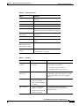
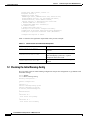
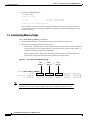
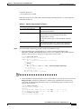
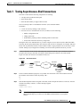
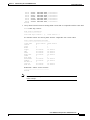
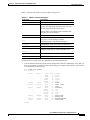
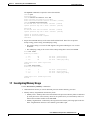
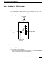
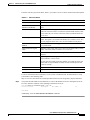
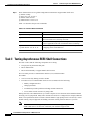
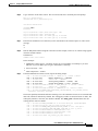
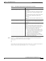
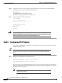
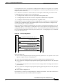
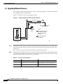
Task 3. Enabling the T1 Controllers
Specify the settings for the T1 controllers. T1 controller settings must match the settings on the
telephone switch side. Mismatched settings cause problems that may not be detected for a long time.
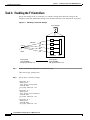
Figure 2-4
Matching T1 Controller Settings
Cisco AS5300
PRI lines
T1
controllers
Framing ESF
Linecode B8ZS
PRI-group timeslots 1-24
Step 1
Must match!
TDM
bus
29653
Telephone
switch
Framing ESF
Linecode B8ZS
PRI-group timeslots 1-24
Define the ISDN switch type and T1 controller settings:
!
isdn switch-type primary-5ess
!
Step 2
Specify the T1 controller settings:
!
controller T1 0
framing esf
clock source line primary
linecode b8zs
pri-group timeslots 1-24
!
controller T1 1
framing esf
clock source line secondary 1
linecode b8zs
pri-group timeslots 1-24
!
controller T1 2
framing esf
linecode b8zs
pri-group timeslots 1-24
2-18
Cisco AS5x00 Case Study for Basic IP Modem Services
11/24/1999
Section 2
Commissioning the Cisco AS5300 Hardware
Enabling the T1 Controllers
!
controller T1 3
framing esf
linecode b8zs
pri-group timeslots 1-24
!
Table 2-4 describes some of the T1-controller concepts that are applied in the previous example.
Table 2-4
T1 Controller Concepts and Descriptions
Concept
Description
Framing type
Defines the control bits and data bits. Cisco supports super frame (SF) and extended
super frame (ESF) for T1s.
ESF—Extended super frame. Required for 64 kb operation on DS0s.
ESF requires 2k-framing bits for synchronization. The remaining 6k is used for
error detection, CRC, and data link monitoring. ESF is recommended for PRI
configurations.
SF—Super frame. SF (D4) is used in channel bank robbed bit signalling (RBS)
configurations. SF uses the framing bit to identify the channel and voice-related
signaling within the frame. SF is not recommended for PRI configurations.
Line code type An encoding method used to allow synchronous data to be transmitted in a
compatible format for T1 transmission. Common line codes are RZ (return to zero),
NRZ (non-return to zero), B8ZS, AMI, and HDB3 (high density bipolar order 3).
AMI—Alternate mark inversion. Signal transitions are referenced by a binary 1
(mark). AMI is used on older T1 circuits. It is not reliable.
B8ZS—Most popular line-code scheme used in North America. To maintain
clock synchronization, B8ZS replaces string 8 binary 0s with variations. B8ZS
is more reliable than AMI, and it should be used with PRI configurations.
Clock source
Refers to both timing and synchronization of the T1 carrier. Timing is encoded within
the transmitted data signal, and it ensures synchronization throughout the network.
By default, the access server uses the line clock from the switch that is coming in on
controller 0. Controller 0 is the primary clock source. Controllers 1 and higher are
secondary clock sources. If a primary clock fails, a secondary clock steps in.
Timeslot
assignment
Timeslots are assigned to channels. For T1 PRI scenarios, all 24 T1 timeslots are
assigned as ISDN PRI channels. After the timeslots are assigned by the pri-group
command, D-channel serial interfaces are automatically created in the configuration
file (for example S0:23, S1:23, and so on).
Cisco AS5x00 Case Study for Basic IP Modem Services
11/24/1999
2-19
Section 2
Enabling the T1 Controllers
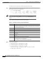
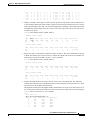
Step 3
Commissioning the Cisco AS5300 Hardware
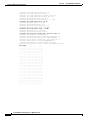
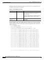
Verify that the controllers are up and no alarms or errors are detected. Error counters are recorded over
a 24-hour period in 15-minute intervals. In the display output, focus on the data in the current interval.
5300-NAS#show controller t1
T1 0 is up.
Applique type is Channelized T1
Cablelength is long gain36 0db
No alarms detected.
Version info of slot 0: HW: 4, Firmware: 16, PLD Rev: 0
Manufacture Cookie Info:
EEPROM Type 0x0001, EEPROM Version 0x01, Board ID 0x42,
Board Hardware Version 1.32, Item Number 73-2217-5,
Board Revision B16, Serial Number 09356963,
PLD/ISP Version 0.0, Manufacture Date 18-Jun-1998.
Framing is ESF, Line Code is B8ZS, Clock Source is Line Primary.
Data in current interval (28 seconds elapsed):
0 Line Code Violations, 0 Path Code Violations
0 Slip Secs, 0 Fr Loss Secs, 0 Line Err Secs, 0 Degraded Mins
0 Errored Secs, 0 Bursty Err Secs, 0 Severely Err Secs, 0 Unavail Secs
Total Data (last 1 15 minute intervals):
12 Line Code Violations, 0 Path Code Violations,
0 Slip Secs, 323 Fr Loss Secs, 5 Line Err Secs, 0 Degraded Mins,
0 Errored Secs, 0 Bursty Err Secs, 0 Severely Err Secs, 323 Unavail Secs
...
Snip
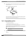
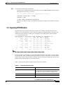
After each controller is correctly set up, clear the counters and look for ongoing line violations and
errors. To do this, enter the clear controller t1 number command followed by the show controller t1
command. In the display output, focus on the data in the current interval. Error counters stop increasing
when the controller is configured correctly.
Tech Tip
The clear controller t1 number command does not reset or bring down the controller.
The T1 stays up. Only the counters are cleared.
If the counters are increasing on a specific T1 controller, look closely at the error statistics. Refer to the
commands in Table 2-5.
Table 2-5
Different Options for the Show Controller T1 Command
Command
Purpose
show controller t1
Provides brief output statistics for the current
interval and the last 24 hours.
show controller t1 number
Displays counters for all 96 intervals.
show controller t1 number | begin Total
Modifies the output as described in the Cisco IOS
configuration guides. The “T” in Total is case
sensitive. (Release 12.0 T is required.)
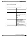
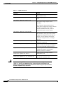
Table 2-6 provides a list of T1 alarm conditions and descriptions from the reference point of the NAS.
2-20
Cisco AS5x00 Case Study for Basic IP Modem Services
11/24/1999
Section 2
Commissioning the Cisco AS5300 Hardware
Table 2-6
Enabling the T1 Controllers
Alarm Conditions
Alarm
Description
CRC Errors
Occurs only in ESF format when a CRC bit has an error.
Excessive CRC Error
Indication (ECRCEI)
Reported in ESF format when 32 of any 33 consecutive CRCs are in
error.
Out of Frame (OOF)
Occurs when the framing pattern for a T1 line has been lost, and data
cannot be extracted. This is a red alarm. In SF and ESF formats, OOF
occurs when any two of four consecutive frame-synchronization bits
are in error.
Loss of Signal (LOS)
Occurs when 175 consecutive 0s are detected in the MC. This is a red
alarm. The signal is recovered if the density of 1s reaches 12.5%. The
recovery happens when four 1s are received within a 32-bit period.
Remote Frame Alarm
(RHEA)
Indicates that an OOF framing pattern occurred at the remote end. This
is a yellow alarm.
Alarm Indication Signal
(AIS)
Indicates to the remote end that the received signal is lost. This is a blue
alarm. AIS occurs when a stream of 1s is received.
Loop Back
Indicates that a remotely initiated loopback (from the network) is in
progress.
Errored Seconds
Depending on the framing format, indicates OOF conditions, frame
slip conditions, or error events.
For SF, errored seconds reports the number of seconds the frame was
in the OOF or slip condition. For ESF, errored seconds reports error
events in seconds.
Bursty Errored Seconds
Reports CRC error conditions in seconds (ESF format only).
Severely Errored Seconds
Reports error events or frame slip conditions in seconds.
For more information about controllers, see the section “Channelized E1 & Channelized T1 Setup
Commands” at the following URL:
http://www.cisco.com/univercd/cc/td/doc/product/software/ios120/12cgcr/dial_r/drprt1/index.htm
Step 4
Verify that the individual serial D channels and B channels are present. In the following example,
B channels S0:0 through S0:22 are rotary members of the signaling D channel S0:23.
5300-NAS#show ip interface brief
Interface
IP-Address
Ethernet0
172.22.66.23
FastEthernet0
unassigned
Loopback0
172.22.99.1
Loopback1
172.22.90.1
Serial0:0
unassigned
Serial0:1
unassigned
Serial0:2
unassigned
Serial0:3
unassigned
Serial0:4
unassigned
Serial0:5
unassigned
Serial0:6
unassigned
Serial0:7
unassigned
Serial0:8
unassigned
Serial0:9
unassigned
Serial0:10
unassigned
OK?
YES
YES
YES
YES
YES
YES
YES
YES
YES
YES
YES
YES
YES
YES
YES
Method
NVRAM
NVRAM
NVRAM
NVRAM
unset
unset
unset
unset
unset
unset
unset
unset
unset
unset
unset
Status
Protocol
up
up
administratively down down
up
up
up
up
down
down
down
down
down
down
down
down
down
down
down
down
down
down
down
down
down
down
down
down
down
down
Cisco AS5x00 Case Study for Basic IP Modem Services
11/24/1999
2-21
Section 2
Configuring the Serial Interfaces
Serial0:11
Serial0:12
Serial0:13
Serial0:14
Serial0:15
Serial0:16
Serial0:17
Serial0:18
Serial0:19
Serial0:20
Serial0:21
Serial0:22
Serial0:23
unassigned
unassigned
unassigned
unassigned
unassigned
unassigned
unassigned
unassigned
unassigned
unassigned
unassigned
unassigned
unassigned
YES
YES
YES
YES
YES
YES
YES
YES
YES
YES
YES
YES
YES
unset
unset
unset
unset
unset
unset
unset
unset
unset
unset
unset
unset
unset
Commissioning the Cisco AS5300 Hardware
down
down
down
down
down
down
down
down
down
down
down
down
up
down
down
down
down
down
down
down
down
down
down
down
down
up
...
Snip
Task 4. Configuring the Serial Interfaces
Configure the serial D channels to route incoming voice calls from the PSTN to the integrated modems.
The behavior of the B channels is controlled by the D channels’ configuration instructions.
The D channel is the signaling channel.
After timeslots are assigned by the pri-group command, D-channel serial interfaces are
automatically created in the configuration file (for example S0:23, S1:23, and so on).
Individual B-channel serial interfaces are created as rotary members of their signaling D channels
(for example S0:0 through S0:22). The D-channel interface functions like a dialer for all the
23 B-channels using the controller.
Table 2-7 describes the relationship between T1 controllers and serial interfaces.
Table 2-7
Step 1
Controller-to-Channel Relationships
T1 Controllers
D Channels
B Channels
Controller T1 0
Interface serial 0:23
S0:0 through S0:22
Controller T1 1
Interface serial 1:23
S1:0 through S1:22
Controller T1 2
Interface serial 2:23
S2:0 through S2:22
Controller T1 3
Interface serial 3:23
S3:0 through S3:22
...
...
...
Apply the isdn incoming-voice modem command to each D-channel serial interface:
!
interface Serial0:23
isdn incoming-voice modem
!
interface Serial1:23
isdn incoming-voice modem
!
interface Serial2:23
isdn incoming-voice modem
2-22
Cisco AS5x00 Case Study for Basic IP Modem Services
11/24/1999
Section 2
Commissioning the Cisco AS5300 Hardware
Configuring the Serial Interfaces
!
interface Serial3:23
isdn incoming-voice modem
!
Different versions of Cisco IOS enables different default commands. Release 12.0(5)T enables the
commands in Table 2-8.
Table 2-8
Release 12.0(5)T Default Commands
Command
Purpose
no ip directed-broadcast
Enhances security by preventing broadcasts to this subnet
from unauthorized sources.
isdn switch-type primary-5ess
The ISDN global switch type value is propagated to the
serial-interface level. This happens during initial
configuration or a reload.
Per interface switch-types are first introduced in Release
11.3AA.
no cdp enable
Step 2
Turns off the cisco discovery protocol (cdp). Otherwise,
the protocol attempts to be negotiated on the PPP links.
Verify that ISDN is functioning properly, and the serial channels are up:
Check the ISDN status. Confirm that Layer 1 reports ACTIVE, and the display field
MULTIPLE_FRAME_ESTABLISHED appears at Layer 2. For PRI lines, the terminal endpoint
identifier (TEI) is always 0. The Layer 3 status reports no active calls.
5300-NAS#show isdn status
Global ISDN Switchtype = primary-5ess
ISDN Serial0:23 interface
dsl 0, interface ISDN Switchtype = primary-5ess
Layer 1 Status:
ACTIVE
Layer 2 Status:
TEI = 0, Ces = 1, SAPI = 0, State = MULTIPLE_FRAME_ESTABLISHED
Layer 3 Status:
0 Active Layer 3 Call(s)
Activated dsl 0 CCBs = 0
The Free Channel Mask: 0x807FFFFF
...
Snip
Verify that PRI is working between the remote switch and the Cisco AS5300. After you enter the
debug isdn q921 command, you should see a SAPI message transmitted and received every
10 seconds. A SAPI message indicates that Layer 2 is functioning properly, and there are no
apparent cable problems.
5300-NAS#debug isdn q921
ISDN Q921 packets debugging is on
5300-NAS#
Sep 23 04:19:07.887: ISDN Se0:23: TX ->
Sep 23 04:19:07.891: ISDN Se0:23: RX <5300-NAS#undebug isdn q921
ISDN Q921 packets debugging is off
RRp sapi = 0
RRf sapi = 0
tei = 0 nr = 23
tei = 0 nr = 23
Cisco AS5x00 Case Study for Basic IP Modem Services
11/24/1999
2-23
Section 2
Configuring Modems and Lines
Step 3
Commissioning the Cisco AS5300 Hardware
Test the configuration by sending a standard telephone (POTS) call into the NAS. The configuration
works if the modem answers (that is, you hear modem squelch), the configuration works. Figure 2-5
shows how this step works.
Figure 2-5
Sending a POTs Telephone Call into a NAS
POTS
PRI
Telephone
switch
ANI
444-1234
DNIS
555-1234
NAS receiving
analog call
29652
Standard POTS
telephone
A different telephone number is associated with each end of the connection. In Figure 2-5, the called
number 555-1234 is assigned to the PRI trunk. This number is dialed from the POTS telephone. The
calling number 444-1234 is assigned to the POTS telephone line.
Task 5. Configuring Modems and Lines
Modems and lines are configured after:
The ISDN channels are operational
POTS telephone calls are successfully routed to the modems
Each modem is mapped to a dedicated asynchronous line inside the NAS. After the modem inout
command is applied to the lines, the NAS is ready to accept modem calls.
AAA security is applied to the lines by the aaa new-model command and aaa authentication login
default local command. AAA performs login authentication by using the local username database. The
login keyword authenticates EXEC shell users.
Note
Step 1
The modem speed 115200 bps and hardware flow control are the default settings
for integrated modems.
Support incoming and outgoing modem calls. In this example, the NAS has 96 integrated modems.
!
line 1 96
modem InOut
!
2-24
Cisco AS5x00 Case Study for Basic IP Modem Services
11/24/1999
Section 2
Commissioning the Cisco AS5300 Hardware
Step 2
Configuring Modems and Lines
Verify that the asynchronous TTY lines support incoming and outgoing calls. These lines are simulated
R2-232 ports.
5300-NAS#show line
Tty Typ
Tx/Rx
*
0 CTY
1 TTY
2 TTY
3 TTY
4 TTY
5 TTY
6 TTY
7 TTY
8 TTY
9 TTY
10 TTY
A
-
Modem
inout
inout
inout
inout
inout
inout
inout
inout
inout
inout
Roty AccO AccI
-
Uses
0
0
0
0
0
0
0
0
0
0
0
Noise
0
0
0
0
0
0
0
0
0
0
0
Overruns
0/0
0/0
0/0
0/0
0/0
0/0
0/0
0/0
0/0
0/0
0/0
Int
-
...
Snip
Step 3
(Optional) Choose a specific line and inspect the modem-to-TTY association. In this example, TTY 1
is associated with modem 1/0. The modem state is idle because no users have dialed in yet.
5300-NAS#show line 1
Tty Typ
Tx/Rx
1 TTY
A Modem
- inout
Roty AccO AccI
-
Uses
0
Noise
0
Overruns
0/0
Int
-
Line 1, Location: "", Type: ""
Length: 24 lines, Width: 80 columns
Status: No Exit Banner
Capabilities: Hardware Flowcontrol In, Hardware Flowcontrol Out
Modem Callout, Modem RI is CD, Integrated Modem
Modem state: Idle
modem(slot/port)=1/0, state=IDLE
dsx1(slot/unit/channel)=NONE, status=VDEV_STATUS_UNLOCKED
Modem hardware state: CTS noDSR DTR noRTS
Special Chars: Escape Hold Stop Start Disconnect Activation
^^x
none
none
Timeouts:
Idle EXEC
Idle Session
Modem Answer Session
Dispatch
00:10:00
never
none
not set
Idle Session Disconnect Warning
never
Login-sequence User Response
00:00:30
Autoselect Initial Wait
not set
Modem type is unknown.
Session limit is not set.
Time since activation: never
Editing is enabled.
History is enabled, history size is 10.
DNS resolution in show commands is enabled
Full user help is disabled
Allowed transports are pad telnet rlogin udptn v120 lapb-ta. Preferred is pad t
elnet rlogin udptn v120 lapb-ta.
No output characters are padded
No special data dispatching characters
5300-NAS#
Cisco AS5x00 Case Study for Basic IP Modem Services
11/24/1999
2-25
Section 2
Enabling IP Basic Setup
Commissioning the Cisco AS5300 Hardware
Task 6. Enabling IP Basic Setup
Fine tune the IP routing functions and domain-name services for EXEC shell users.
Step 1
Optimize IP routing functions in global configuration mode:
ip subnet-zero
no ip source-route
ip classless
Table 2-9 describes the previous commands.
Table 2-9
Step 2
IP Routing Commands
Command
Purpose
ip subnet-zero
Specifies that 172.22.0.0 is a legal subnet.
no ip source-route
Tightens security by ensuring that IP-header packets
cannot define their own paths through the network
access server (NAS).
ip classless
Ensures that all unknown subnets use the default route.
In global configuration mode, enter domain-name service commands to support EXEC shell users:
ip
ip
ip
ip
ip
domain-lookup
host dirt 172.22.100.9
domain-name mauionions.com
name-server 172.22.11.10
name-server 172.22.11.11
Table 2-10 describes the previous commands.
Table 2-10 Domain-Name Commands
2-26
Command
Purpose
ip domain-lookup
Enables IP domain-name lookups.
ip host dirt 172.22.100.9
Creates a local name-to-address map. When the NAS is not
entered in a DNS server, this map is useful.
ip domain-name mauionions.com
Tells the NAS how to qualify DNS lookups. In this example,
mauonions.com is appended to the end of each looked-up name.
ip name-server 172.22.11.10
ip name-server 172.22.12.11
Specifies the primary and secondary name servers. The ip
name-server command is used for mapping names to IP
addresses.
Cisco AS5x00 Case Study for Basic IP Modem Services
11/24/1999
Section 2
Commissioning the Cisco AS5300 Hardware
Testing Asynchronous-Shell Connections
Task 7. Testing Asynchronous-Shell Connections
This task verifies that the following components are working:
The physical asynchronous data path
Basic modem links
Basic IP functionality to support shell sessions
The Cisco IOS provides a command-line interface (CLI) called the EXEC.
The EXEC:
Can be accessed by dialing in with a modem
Provides access to terminal-shell services (no PPP) to do the following:
` Modify configuration files
` Change passwords
` Troubleshoot possible problems including modem connections
` Access other network resources by using telnet
During this task, some administrators try to make complex services function such as PPP-based Web
browsing. Do not jump ahead. Many other elements still need to be configured (for example, PPP and
IPCP). The asynchronous-shell test ensures that the EXEC’s login prompt can be accessed by a client
modem. Taking a layered approach to building a network isolates problems and saves you time.
Step 1
Locate a client PC, client modem, and analog line. From the client PC, open a terminal emulation
program (such as Hyper Terminal, not Dial-Up Networking) and connect to the client modem.
Figure 2-6 shows the network environment for this test.
Figure 2-6
Test Environment
POTS line
PRI lines
Default
gateway
PSTN
Client PC
Client
modem
Step 2
24513
Cisco AS5300
with integrated
modems
From a terminal-emulation program, test your RS-232 connection to the client modem. Enter the
at command. The modem returns the prompt “OK.”
at
OK
Step 3
Dial the PRI telephone number assigned to the NAS (in this example the number is 5551234). After the
modem successfully connects, a connect message appears.
atdt5551234
CONNECT 28800 V42bis
Note
Many modems support the a/ command, which recalls the last AT command. The
ath command hangs up a modem call. The atdl command dials the last telephone
number.
Cisco AS5x00 Case Study for Basic IP Modem Services
11/24/1999
2-27
Section 2
Testing Asynchronous-Shell Connections
Step 4
Commissioning the Cisco AS5300 Hardware
Log into the EXEC session:
This is a secured device.
Unauthorized use is prohibited by law.
User Access Verification
Username: dude
Password:
5300-NAS>
Step 5
Identify the line where the call landed. The following example shows that line TTY 1 accepted the call.
The call has been up and active for 48 seconds.
5300-NAS>show caller
Line
con 0
tty 1
User
admin
dude
Service
TTY
TTY
Active
Time
00:05:33
00:00:48
Idle
Time
00:00:00
00:00:22
5300-NAS>show caller user dude
User: dude, line tty 1, service TTY
Active time 00:01:12, Idle time 00:00:46
Timeouts:
Absolute Idle
Idle
Session
Exec
Limits:
00:10:00
Disconnect in:
00:09:13
TTY: Line 1
DS0: (slot/unit/channel)=0/0/0
Line: Baud rate (TX/RX) is 115200/115200, no parity, 1 stopbits, 8 databits
Status: Ready, Active, No Exit Banner
Capabilities: Hardware Flowcontrol In, Hardware Flowcontrol Out
Modem Callout, Modem RI is CD, Integrated Modem
Modem State: Ready
Note
Step 6
The show caller command is added to the Cisco IOS software in Release 11.3 AA
and 12.0 T. If your software release does not support this command, use the
show user command.
Test the IP functionality to support shell sessions. From the NAS, telnet to another device in your
network.
5300-NAS>telnet 172.22.66.26
Trying 172.22.66.26 ... Open
User Access Verification
Username: admin
Password:
5800-NAS>
5800-NAS>telnet people
Translating "people"...domain server (172.22.11.10) [OK]
Trying people.cisco.com (172.22.2.2)... Open
SunOS 5.6
2-28
Cisco AS5x00 Case Study for Basic IP Modem Services
11/24/1999
Section 2
Commissioning the Cisco AS5300 Hardware
Confirming the Final Running-Config
login: dude
Password:
Last login: Wed Oct 6 08:57:46 from dhcp-aus-163-236
Sun Microsystems Inc.
SunOS 5.6
Generic August 1997
/cms/resource/.cmsrc: No such file or directory
people%
Task 8. Confirming the Final Running-Config
The final running configuration looks like this:
5300-NAS#show running-config
Building configuration...
Current configuration:
!
version 12.0
service timestamps debug datetime msec
service timestamps log datetime msec
service password-encryption
!
hostname 5300-NAS
!
aaa new-model
aaa authentication login default local
aaa authentication ppp default if-needed local
enable secret 5 $1$Ec9Q$KsERiSHdKGL/rGaewXeIz.
!
username admin password 7 045802150C2E
username dude password 7 070C285F4D06
spe 1/0 1/7
firmware location bootflash:mica-modem-pw.2.7.1.0.bin
spe 2/0 2/7
firmware location bootflash:mica-modem-pw.2.7.1.0.bin
!
resource-pool disable
!
ip subnet-zero
no ip source-route
ip host dirt 172.22.100.9
ip domain-name mauionions.com
ip name-server 172.22.11.10
ip name-server 172.22.12.11
!
isdn switch-type primary-5ess
mta receive maximum-recipients 0
!
controller T1 0
framing esf
clock source line primary
linecode b8zs
pri-group timeslots 1-24
!
controller T1 1
framing esf
clock source line secondary 1
linecode b8zs
Cisco AS5x00 Case Study for Basic IP Modem Services
11/24/1999
2-29
Confirming the Final Running-Config
Section 2
Commissioning the Cisco AS5300 Hardware
pri-group timeslots 1-24
!
controller T1 2
framing esf
linecode b8zs
pri-group timeslots 1-24
!
controller T1 3
framing esf
linecode b8zs
pri-group timeslots 1-24
!
process-max-time 200
!
interface Loopback0
ip address 172.22.99.1 255.255.255.255
no ip directed-broadcast
!
interface Loopback1
ip address 172.22.90.1 255.255.255.0
no ip directed-broadcast
!
interface Ethernet0
ip address 172.22.66.23 255.255.255.0
no ip directed-broadcast
!
interface Serial0:23
no ip address
no ip directed-broadcast
isdn switch-type primary-5ess
isdn incoming-voice modem
fair-queue 64 256 0
no cdp enable
!
interface Serial1:23
no ip address
no ip directed-broadcast
isdn switch-type primary-5ess
isdn incoming-voice modem
fair-queue 64 256 0
no cdp enable
!
interface Serial2:23
no ip address
no ip directed-broadcast
isdn switch-type primary-5ess
isdn incoming-voice modem
fair-queue 64 256 0
no cdp enable
!
interface Serial3:23
no ip address
no ip directed-broadcast
isdn switch-type primary-5ess
isdn incoming-voice modem
fair-queue 64 256 0
no cdp enable
!
interface FastEthernet0
no ip address
no ip directed-broadcast
shutdown
!
no ip http server
2-30
Cisco AS5x00 Case Study for Basic IP Modem Services
11/24/1999
Section 2
Commissioning the Cisco AS5300 Hardware
What to do Next
ip classless
ip route 0.0.0.0 0.0.0.0 172.22.66.1
!
banner login ^C
This is a secured device.
Unauthorized use is prohibited by law.
^C
!
line con 0
transport input none
line 1 96
modem InOut
line aux 0
line vty 0 4
!
end
What to do Next
Perform the tasks in the section “Verifying Modem Performance.”
Cisco AS5x00 Case Study for Basic IP Modem Services
11/24/1999
2-31
What to do Next
2-32
Section 2
Commissioning the Cisco AS5300 Hardware
Cisco AS5x00 Case Study for Basic IP Modem Services
11/24/1999
S E C T I O N
3
Commissioning the Cisco AS5800 Hardware
In this Section
This section describes how to configure the Cisco AS5800 to support terminal EXEC shell services
and login prompts for client modems.
The following subsections are provided:
Understanding the Basic Hardware Architecture
Task 1. Verifying Basic Setup
Task 2. Configuring Cisco IOS Basics
Task 3. Enabling the T3/T1 Controllers
Task 4. Configuring the Serial Interfaces
Task 5. Configuring Modems and Lines
Task 6. Enabling IP Basic Setup
Task 7. Testing Asynchronous EXEC Shell Connections
Task 8. Confirming the Final Running-Config
In this case study, THEnet commissions the Cisco AS5800 network access server (NAS). Local-based
authentication is used. After the Cisco AS5800 is commissioned, THEnet configures and tests PPP as
described in “Configuring PPP and Authentication.” In the future, THEnet will use a AAA RADIUS
server.
Note
For a description of terminal EXEC shell services, see the section “Task 7. Testing
Asynchronous EXEC Shell Connections.”
Understanding the Basic Hardware Architecture
To build an access network by using the Cisco AS5800, you need to understand the following:
The Cisco 7206 Router Shelf and the Cisco DS5814 Dial Shelf
Call-Processing Components
Cisco AS5x00 Case Study for Basic IP Modem Services
11/24/1999
3-1
Section 3
Understanding the Basic Hardware Architecture
Commissioning the Cisco AS5800 Hardware
The Cisco 7206 Router Shelf and the Cisco DS5814 Dial Shelf
The Cisco AS5800 access server contains:
A Cisco 7206 router shelf (egress). It connects to the IP backbone.
A Cisco DS5814 dial shelf (ingress). It connects to the PSTN.
Figure 3-1 shows the Cisco AS5800’s system architecture for this case study:
Figure 3-1
Cisco AS5800 System Architecture
System
controller
shelf
Network
element
management
server
(SNMP)
Cisco
SC3640
Router shelf
Cisco
shelf ID=0
7206
FE 0/1/0
AAA server
DSI
port adapter
0/2/0
Dial shelf
shelf ID=1
T3
IP
backbone
Backbone
router
Cisco DS5814
Modem cards
DSC
1/0/0
Dial shelf
interconnect
cable
PSTN
Client
modem
0 1 2 3 . . . . . . . . . . . . 13
Slot numbers
Note
3-2
30043
Client
PC
PRI
The Cisco IOS uses a three-element notation to specify interface and port
locations: shelf/slot/port.
Cisco AS5x00 Case Study for Basic IP Modem Services
11/24/1999
Section 3
Commissioning the Cisco AS5800 Hardware
Understanding the Basic Hardware Architecture
The Cisco 7206 router shelf contains the following:
` Port adapters. In this case study, the Cisco 7206 uses Fast Ethernet (FE) 0/1/0 to connect to the
IP backbone.
` A dial shelf interconnect (DSI) port adapter. In this case study, the adapter is located at 0/2/0.
The Cisco 7206 communicates with the Cisco DS5814 dial shelf through an external dial shelf
interconnect cable. The cable connects from the DSI port adapter to the dial shelf controller
(DSC) card.
The Dial Shelf Interconnect Protocol (DSIP) enables communication between the Cisco 7206
and the Cisco DS5814.
` Service adapters (for example, compression and encryption).
` By default, a shelf ID of 0 is assigned to the router shelf.
The Cisco DS5814 dial shelf contains the following:
` Dial shelf controller (DSC) cards. They fit in slots 12 or 13 only. If you have only one
DSC card, slot 12 is recommended. One DSC card is used in this case study.
The DSC card contains its own Cisco IOS image. For maintenance purposes only, the card can
be accessed through its console port and Ethernet interface. No IP packets originating from any
trunk or modem cards go out this Ethernet interface.
` T3/T1/E3/E1 cards. They connect to the PSTN and fit in slots 0 through 5 only. Slots 0 and 1
are recommended. In this case study, one T3 trunk card is located at 1/0/0.
` Modem/voice cards. They fit in slots 0 through 11. In this case study, nine modem cards are
installed. The first modem card is in slot 2. The line-modem range is 1/2/00 to 1/10/143.
` By default, a shelf ID of 1 is assigned to the dial shelf.
The Cisco SC3640 system controller is an external management subsystem. It interfaces with the
Cisco 7206 and provides the following functions:
` SNMP and syslog off loading
` Out-of-band console access
Call-Processing Components
As shown in Figure 3-2, the following components are used to process a call:
Client modems and ISDN routers dial into the access server through the PSTN.
Asynchronous PPP calls (analog) connect to modems inside the access server.
Each modem inside the access server provides a corresponding TTY line and asynchronous
interface for terminating character and packet mode services.
Asynchronous interfaces clone their configurations from a group-async interface.
Synchronous PPP calls (digital) connect to serial interface channels (for example, S1/0/0:0:0
and S1/0/0:0:1).
Synchronous interfaces clone their configurations from a dialer interface.
Cisco AS5x00 Case Study for Basic IP Modem Services
11/24/1999
3-3
Section 3
Understanding the Basic Hardware Architecture
Figure 3-2
Commissioning the Cisco AS5800 Hardware
Cisco AS5800 Call-Processing Components
Inside a Cisco
network access server
IP
network
Routing and
switching engine
Group-async
interface
Dialer interface
controlling the
D channels
Cloning
Asynchronous
interfaces
Cloning
TTY lines
Serial interface
channels S1/0/0:0:0,
S1/0/0:0:1...
Modems
TDM bus
T1 controllers
PRI lines
PSTN
POTS line
Client
PC
BRI line
Client
modem
ISDN
router
Client
PC
Legend
= Synchronous PPP
= Configuration
template
3-4
32400
= Asynchronous PPP
Cisco AS5x00 Case Study for Basic IP Modem Services
11/24/1999
Section 3
Commissioning the Cisco AS5800 Hardware
Verifying Basic Setup
One asynchronous PPP call consumes:
One T1 DS0 channel
One channel in a TDM bus
One integrated modem
One TTY line
One asynchronous interface
One synchronous PPP call consumes:
Tech Tip
One T1 DS0 channel
One serial interface channel
Synchronous PPP calls require HDLC resources. Each T3 trunk card is limited to 256
HDLC resources. T1 trunk cards do not have HDLC resource limitations.
Task 1. Verifying Basic Setup
Verify that basic system components are functioning:
1.1 Analyzing the System Boot Dialog
1.2 Matching the Cisco IOS Images
1.3 Inspecting the Dial Shelf
1.4 Understanding DSIP Commands
1.5 Checking the Initial Running-Config
1.6 Exploring the Cisco IOS File System
1.7 Investigating Memory Usage
1.8 Inspecting CPU Utilization
Cisco AS5x00 Case Study for Basic IP Modem Services
11/24/1999
3-5
Section 3
Verifying Basic Setup
Commissioning the Cisco AS5800 Hardware
1.1 Analyzing the System Boot Dialog
To view the boot sequence through a terminal session, you must have a console connection to the access
server before it powers up.
Caution
Always power up the dial shelf before the router shelf. The DSC card checks the dial
shelf’s inventory, which requires extra time. After two minutes, power up the router shelf.
The router shelf depends on the DSC card for the dial shelf’s inventory report.
The following boot sequence occurs. Event numbers and comments are inserted in the example to
describe the boot sequence.
System Bootstrap, Version 11.1(13)CA, EARLY DEPLOYMENT RELEASE SOFTWARE (fc1)
Copyright (c) 1997 by cisco Systems, Inc.
C7200 processor with 131072 Kbytes of main memory
Self decompressing the image : #################################################
################################################################################
################################################################ [OK]
%PA-2-UNDEFPA: Undefined Port Adaptor type 106 in bay 2
%SYS-4-CONFIG_NEWER: Configurations from version 12.0 may not be correctly under
stood.
%OIR-3-SEATED: Insert/removal failed (slot 2), check card seating
%OIR-3-SEATED: Insert/removal failed (slot 2), check card seatingCCCCCCCCCCCCCCC
CCCCCCCCCCCCCCCCCCCCCCCCCCCCCCCCCCCCCCCCCCCCCCCCCCCCCCCCCCCCCCCCCCCCCCCCCCCCCCCC
CCCCCCCCCCCCCCCCCCCCCCCCCCCCCCCCCCCCCCCCCCCCCCCCCCCCCCCCCCCCCCCCCCCCCCCCCCCCCCCC
CCCCCCCCCCCCCCCCCCCCCCCCCCCCCCCCCCCCCCCCCCCCCCCC
Read 7314384 bytes from file slot0:c5800-p4-mz.120-4.XL1.bin
Self decompressing the image : #################################################
################################################################################
################################################################################
################################################################################
################################################################################
################################################################################
################################################################################
################################################################################
############################ [OK]
1.
In the previous segment, the NAS decompresses the system boot image, tests the NVRAM for
validity, and decompresses the Cisco IOS image.
Sometimes boot images do not support hardware cards. Sample error messages look like this:
%PA-2-UNDEFPA: Undefined Port Adapter
%OIR-3-SEATED: Insert/removal failed
Ignore these messages. However, do not ignore error messages that appear after the Cisco IOS
image decompresses.
3-6
Cisco AS5x00 Case Study for Basic IP Modem Services
11/24/1999
Section 3
Commissioning the Cisco AS5800 Hardware
Verifying Basic Setup
Restricted Rights Legend
Use, duplication, or disclosure by the Government is
subject to restrictions as set forth in subparagraph
(c) of the Commercial Computer Software - Restricted
Rights clause at FAR sec. 52.227-19 and subparagraph
(c) (1) (ii) of the Rights in Technical Data and Computer
Software clause at DFARS sec. 252.227-7013.
cisco Systems, Inc.
170 West Tasman Drive
San Jose, California 95134-1706
Cisco Internetwork Operating System Software IOS (tm) 5800 Software (C5800-P4-M),
Version 12.0(4)XL1, EARLY DEPLOYMENT RELEASE SOFTWARE (fc1)
TAC:Home:SW:IOS:Specials for info
Copyright (c) 1986-1999 by cisco Systems, Inc.
Compiled Thu 12-Aug-99 13:16 by ayeh
Image text-base: 0x60008900, data-base: 0x611A6000
cisco 7206 (NPE200) processor with 114688K/16384K bytes of memory.
R5000 CPU at 200Mhz, Implementation 35, Rev 2.1, 512KB L2 Cache
6 slot midplane, Version 1.3
Last reset from power-on
X.25 software, Version 3.0.0.
Bridging software.
SuperLAT software (copyright 1990 by Meridian Technology Corp).
1 FastEthernet/IEEE 802.3 interface(s)
1296 terminal line(s)
1 Channelized T3 port(s)
125K bytes of non-volatile configuration memory.
4096K bytes of packet SRAM memory.
20480K bytes of Flash PCMCIA card at slot 0 (Sector size 128K).
4096K bytes of Flash internal SIMM (Sector size 256K).
2.
The following components are detected: Cisco IOS Release, available memory, and available
interfaces.
If a hardware card is not recognized, verify that you are running the optimum version of Cisco IOS.
Refer to the Hardware-Software Compatibility Matrix at:
http://cco-sj-1.cisco.com/cgi-bin/front.x/Support/HWSWmatrix/hwswmatrix.cgi
Cisco AS5x00 Case Study for Basic IP Modem Services
11/24/1999
3-7
Section 3
Verifying Basic Setup
Commissioning the Cisco AS5800 Hardware
--- System Configuration Dialog --Would you like to enter the initial configuration dialog? [yes/no]: no
3.
Because the NAS has never been configured, the Cisco IOS cannot find a startup-config file. Abort
the configuration dialog. In this case study, the Cisco IOS is configured manually. The automatic
setup script is not used. Manually configuring the Cisco IOS develops your expertise.
00:00:52:
00:00:53:
00:00:56:
00:02:05:
00:02:06:
00:02:06:
00:02:06:
00:02:06:
00:02:06:
00:02:06:
00:02:06:
00:02:06:
00:02:06:
%DSIPPF-5-DS_HELLO: DSIP Hello from shelf 1 slot
%DSC_REDUNDANCY-3-BICLINK: Switching to DSC 12
%DSC_REDUNDANCY-3-BICLINK: Link to active DSC up
%DSIPPF-5-DS_HELLO: DSIP Hello from shelf 1 slot
%DSIPPF-5-DS_HELLO: DSIP Hello from shelf 1 slot
%DSIPPF-5-DS_HELLO: DSIP Hello from shelf 1 slot
%DSIPPF-5-DS_HELLO: DSIP Hello from shelf 1 slot
%DSIPPF-5-DS_HELLO: DSIP Hello from shelf 1 slot
%DSIPPF-5-DS_HELLO: DSIP Hello from shelf 1 slot
%DSIPPF-5-DS_HELLO: DSIP Hello from shelf 1 slot
%DSIPPF-5-DS_HELLO: DSIP Hello from shelf 1 slot
%DSIPPF-5-DS_HELLO: DSIP Hello from shelf 1 slot
%DSIPPF-5-DS_HELLO: DSIP Hello from shelf 1 slot
12 Succeeded
0 Succeeded
2 Succeeded
3 Succeeded
4 Succeeded
5 Succeeded
6 Succeeded
7 Succeeded
8 Succeeded
9 Succeeded
10 Succeeded
Press RETURN to get started!
Router>
4.
By using the DSIP protocol, the router shelf detects the state of each card in the dial shelf.
Depending on how many cards are in the dial shelf, there is a delay of 60 to 120 seconds before the
“DSIP Hello” messages are displayed on your terminal session.
After the Cisco AS5800 is powered up, enter the show environment command. Verify that there are
no critical grounding, heating, or power problems. The following example shows a normal operating
environment.
5800-NAS>show environment
All measured values are normal
5800-NAS>show environment all
Power Supplies:
Power supply 1 is empty.
Power supply 2 is Zytek AC Power Supply. Unit is on.
Temperature readings:
chassis inlet
measured at
chassis outlet 1 measured at
chassis outlet 2 measured at
chassis outlet 3 measured at
Voltage readings:
+3.45 V measured
+5.15 V measured
+12.15 measured
-11.95 measured
at
at
at
at
25C/77F
27C/80F
33C/91F
41C/105F
+3.49 V
+5.21 V
+12.34 V
-11.81 V
Envm stats saved 1 time(s) since reload
5800-NAS>
3-8
Cisco AS5x00 Case Study for Basic IP Modem Services
11/24/1999
Section 3
Commissioning the Cisco AS5800 Hardware
Verifying Basic Setup
1.2 Matching the Cisco IOS Images
The dial shelf and router shelf run separate Cisco IOS images:
Both images must be from the same Cisco IOS Release. They must match. In this case study, the
Cisco IOS release is 12.0(4)XL1.
The router shelf’s image is in the Cisco 7206’s Flash memory. It begins with “c5800.” The dial
shelf’s image is in the DSC card. It begins with “dsc.”
On the router shelf, check the Cisco IOS image, uptime, and restart reason:
Router#show version
Cisco Internetwork Operating System Software IOS (tm) 5800 Software (C5800-P4-M), Version
12.0(4)XL1, EARLY DEPLOYMENT RELEASE SOFTWARE (fc1)
TAC:Home:SW:IOS:Specials for info
Copyright (c) 1986-1999 by cisco Systems, Inc.
Compiled Thu 12-Aug-99 13:16 by ayeh
Image text-base: 0x60008900, data-base: 0x611A6000
ROM: System Bootstrap, Version 11.1(13)CA, EARLY DEPLOYMENT RELEASE SOFTWARE (fc1)
BOOTFLASH: 7200 Software (C7200-BOOT-M), Version 11.1(24)CC, EARLY DEPLOYMENT RELEASE
SOFTWARE (fc1)
Router uptime is 2 minutes
System returned to ROM by reload
System image file is "slot0:c5800-p4-mz.120-4.XL1.bin"
cisco 7206 (NPE200) processor with 114688K/16384K bytes of memory.
R5000 CPU at 200Mhz, Implementation 35, Rev 2.1, 512KB L2 Cache
6 slot midplane, Version 1.3
Last reset from power-on
X.25 software, Version 3.0.0.
Bridging software.
SuperLAT software (copyright 1990 by Meridian Technology Corp).
1 FastEthernet/IEEE 802.3 interface(s)
1296 terminal line(s)
1 Channelized T3 port(s)
125K bytes of non-volatile configuration memory.
4096K bytes of packet SRAM memory.
20480K bytes of Flash PCMCIA card at slot 0 (Sector size 128K).
4096K bytes of Flash internal SIMM (Sector size 256K).
Configuration register is 0x2102
Cisco AS5x00 Case Study for Basic IP Modem Services
11/24/1999
3-9
Section 3
Verifying Basic Setup
Commissioning the Cisco AS5800 Hardware
Table 3-1 describes the significant output fields in the previous display:
Table 3-1
Show Version Command Field Descriptions
Field
Description
5800 Software (C5800-P4-M), Version
12.0(4)XL1
Cisco IOS version.
Router uptime is 2 minutes
Reports the router’s uptime. Watch for
unscheduled reloads.
System returned to ROM by reload
Describes why the access server last reloaded.
If the field displays “power-on,” a power
interruption caused the reload.
System image file is
"slot0:c5800-p4-mz.120-4.XL1.bin"
The Cisco 7206 router shelf booted from the
external PCMCIA Flash card at slot 0.
The router shelf does not have an internal
Flash. If the PCMCIA Flash card is missing,
the router shelf will not boot.
On the dial shelf, check the Cisco IOS image, uptime, and restart reason. If you do not have a physical
console connection to the dial shelf, enter the execute-on slot [12 | 13] show version command.
The DSC can be in slot 12 or 13.
Router#execute-on slot 12 show version
DA-Slot12>
Cisco Internetwork Operating System Software IOS (tm) 5800 Software (C5800-DSC-M),
Version 12.0(4)XL1, EARLY DEPLOYMENT RELEASE SOFTWARE (fc1)
TAC:Home:SW:IOS:Specials for info
Copyright (c) 1986-1999 by cisco Systems, Inc.
Compiled Thu 12-Aug-99 18:48 by ayeh
Image text-base: 0x600088F0, data-base: 0x60520000
ROM: System Bootstrap, Version 11.3(1)AA, EARLY DEPLOYMENT RELEASE SOFTWARE (fc1)
ROM: 5800 Software (C5800-DSC-M), Version 11.3(9)AA2, EARLY DEPLOYMENT RELEASE SOFTWARE
(fc1)
DA-Slot12 uptime is 20 hours, 38 minutes
System returned to ROM by reload
System image file is "slot0:dsc-c5800-mz.120-4.XL1.bin"
cisco c5800 (R4K) processor with 24576K/8192K bytes of memory.
R4700 CPU at 150Mhz, Implementation 33, Rev 1.0, 512KB L2 Cache
Last reset from power-on
1 Ethernet/IEEE 802.3 interface(s)
2 Dial Shelf Interconnect(DSI) FE interface(s)
123K bytes of non-volatile configuration memory.
8192K bytes of Flash PCMCIA card at slot 0 (Sector size 128K).
4096K bytes of Flash internal SIMM (Sector size 256K).
Configuration register is 0x2102
3-10
Cisco AS5x00 Case Study for Basic IP Modem Services
11/24/1999
Section 3
Commissioning the Cisco AS5800 Hardware
Verifying Basic Setup
1.3 Inspecting the Dial Shelf
Verify that the feature boards are up (T3, T1, E3, E1, modem, or voice):
Router#show dial-shelf
Slot
Board
CPU
Type
Util
0
CT3
0%/0%
2 Modem(DMM) 20%/20%
3 Modem(DMM)
0%/0%
4 Modem(DMM) 20%/20%
5 Modem(DMM) 20%/20%
6 Modem(DMM) 40%/40%
7 Modem(DMM) 40%/40%
8 Modem(DMM) 35%/35%
9 Modem(DMM)
0%/0%
10 Modem(DMM) 20%/20%
12
DSC
0%/0%
Dial shelf set for auto
Router#
DRAM
Total (free)
21598976( 81%)
46764800( 86%)
46764800( 86%)
46764800( 86%)
46764800( 86%)
46764800( 86%)
46764800( 86%)
46764800( 86%)
46764800( 86%)
46764800( 86%)
19097792( 79%)
boot
I/O Memory
Total (free)
8388608( 41%)
16777216( 74%)
16777216( 74%)
16777216( 74%)
16777216( 74%)
16777216( 74%)
16777216( 74%)
16777216( 74%)
16777216( 74%)
16777216( 74%)
8388608( 66%)
State
Up
Up
Up
Up
Up
Up
Up
Up
Up
Up
Up
Elapsed
Time
00:01:35
00:01:35
00:01:35
00:01:35
00:01:35
00:01:35
00:01:35
00:01:35
00:01:35
00:01:34
00:02:49
Always power up the dial shelf before the router shelf. Allow two to three minutes for the DSC card
to take an inventory of the dial shelf.
If the DSC card goes down after the feature boards are up, the system will still function properly.
This event will not bring down the system. However, online insertion and removal (OIR) will not
work.
Possible dial-shelf states include: unknown, down, resetting, booting, and up. The “Up” state means
that the card can communicate with the router shelf.
Each modem board contains its own DRAM memory. Double-density modem modules (DMM)
require at least 64 MB of memory with Release 12.0. Hex modem modules (HMM) require at least
32 MB with Release 11.3. Each card performs its own call processing.
A fully populated DMM card contains 144 modems. The dial shelf in this case study contains
1296 modems.
A normal CPU utilization range for modem boards is between 20% to 40%.
DSC Troubleshooting Tips
If the DSC card does not come up, perform the following troubleshooting steps. If the DSC card never
comes up, the feature boards in the dial shelf cannot communicate with the router shelf.
Step 1
Look for LED lights on the DSC card. If the lights are off, try re-seating the card.
Step 2
Verify that the DSI port adapter on the Cisco 7206 is inserted correctly.
Step 3
Verify that the cable between the DSI port adapter and the DSC card is connected correctly.
Cisco AS5x00 Case Study for Basic IP Modem Services
11/24/1999
3-11
Section 3
Verifying Basic Setup
Step 4
Commissioning the Cisco AS5800 Hardware
From the Cisco 7206, verify that the DSI-Fast Ethernet interface and line protocol are up:
Router>show dsi
DSI-Fastethernet0/2/0 is up, line protocol is up
Hardware is DEC21140A, address is 0030.f2f5.1438 (bia 0030.f2f5.1438)
MTU 0 bytes, BW 100000 Kbit, DLY 100 usec,
reliability 255/255, txload 1/255, rxload 1/255
Encapsulation ARPA, loopback not set
Keepalive set (10 sec)
Full-duplex, 100Mb/s, 100BaseTX/FX
ARP type: ARPA, ARP Timeout 04:00:00
Last input 00:00:00, output 00:00:00, output hang never
Last clearing of "show interface" counters never
Queueing strategy: fifo
Output queue 0/40, 0 drops; input queue 0/75, 0 drops
5 minute input rate 0 bits/sec, 0 packets/sec
5 minute output rate 0 bits/sec, 0 packets/sec
...
Snip
The following example shows a dial shelf interconnection that changes state to up after the DSC card
reloads. Loss of DSIP Keepalive messages indicate no communication between the router shelf and dial
shelf. After DSIP Hello messages succeed, the Fast Ethernet DSI-Tx 0 and DSI-Rx 1 change their state
to up. Until these interfaces are up, the router shelf and dial shelf cannot communicate. No debug
commands are used to create these console messages; however, the terminal monitor command is
required to watch them.
Router#
00:04:29:
00:05:12:
00:05:18:
00:00:03:
00:00:03:
00:00:03:
Router#
Note
%DSIPPF-5-DS_KEEPALIVE_LOSS: DSIP Keepalive Loss from shelf 1 slot 12
%DSIPPF-5-DS_HELLO: DSIP Hello from shelf 1 slot 12 Succeeded
%DIAL12-3-MSG:
%LINK-3-UPDOWN: Interface DSI-Tx-FastEthernet0, changed state to up
%LINK-3-UPDOWN: Interface DSI-Rx-FastEthernet1, changed state to up
%LINK-3-UPDOWN: Interface Ethernet0, changed state to up
In a production environment, verify that console logging is disabled. Enter the
show logging command. If logging is enabled, the access server might intermittently
freeze up as soon as the console port gets overloaded with log messages. Enter the
no logging console command.
The following messages appear on the console-terminal session after the DSC card is physically
removed from slot 12 and re-inserted. Approximately 120 seconds elapse before all these messages
appear.
Router>
04:41:42:
04:42:13:
down
04:42:14:
04:42:36:
04:42:36:
04:42:46:
04:42:46:
04:42:53:
04:44:59:
3-12
%DSC_REDUNDANCY-3-BICLINK: Link to active DSC down
%ISDN-6-LAYER2DOWN: Layer 2 for Interface Se1/0/0:4:23, TEI 0 changed to
%DSC_REDUNDANCY-3-BICLINK: Link to active DSC up
%DSIPPF-5-DS_KEEPALIVE_LOSS: DSIP Keepalive Loss
%DSIPPF-5-DS_KEEPALIVE_LOSS: DSIP Keepalive Loss
%DSIPPF-5-DS_KEEPALIVE_LOSS: DSIP Keepalive Loss
%DSIPPF-5-DS_KEEPALIVE_LOSS: DSIP Keepalive Loss
%DSIPPF-5-DS_HELLO: DSIP Hello from shelf 1 slot
%DSIPPF-5-DS_HELLO: DSIP Hello from shelf 1 slot
from shelf 1
from shelf 1
from shelf 1
from shelf 1
12 Succeeded
0 Succeeded
slot
slot
slot
slot
2
3
0
12
Cisco AS5x00 Case Study for Basic IP Modem Services
11/24/1999
Section 3
Commissioning the Cisco AS5800 Hardware
Verifying Basic Setup
04:45:02: %DSIPPF-5-DS_HELLO: DSIP Hello from shelf 1 slot 2 Succeeded
04:45:03: %DSIPPF-5-DS_HELLO: DSIP Hello from shelf 1 slot 3 Succeeded
Router>
The following boot sequence occurs in the previous example:
1.
The DSC card takes 32 seconds to boot up. Afterwards, the card checks the dial shelf’s inventory.
2.
The dial shelf exchanges hardware inventory information with the router shelf. After the exchange,
the router shelf instructs the DSC card to load the appropriate boot images into the feature boards.
3.
More than two minutes elapse before the DSC card detects the first “DSIP Hello” message from the
first feature board (in shelf 1 slot 0). If the DSC card never comes up, the feature boards in the dial
shelf cannot communicate with the router shelf.
4.
The router shelf gives the feature boards the appropriate images.
Step 5
If the DSC card is still down, the card might have an incorrect Cisco IOS image, or the Flash card is
missing (ROM monitor mode). Open a physical console connection to the DSC card, copy an image into
boot Flash, and try re-initializing the system.
Step 6
For advanced troubleshooting measures after the DSC card is up, open a virtual-console session to the
DSC card (DA-Slot12). To end the session, enter Ctrl C three times:
Router#dsip console slave
Trying Dial shelf slot 12
Entering CONSOLE for slot
Type "^C^C^C" to end this
12
...
12
session
DA-Slot12>
DA-Slot12#
DA-Slot12#
DA-Slot12#
Terminate NIP IO session? [confirm]
[Connection to Dial shelf slot 12 closed by local host]
Router#
Warning
The router shelf provides the DSC card with the required configuration. Do not change
the DSIP settings in the DSC cards configuration.
Feature Board Troubleshooting Tips
If the show dial-shelf command reports that the feature boards are booting for extended periods of time,
start debugging from the router shelf by using the following commands:
debug dsip transport
debug dsip trace
debug dsip boot
Debug dsip transport shows the registered MAC address sent from each feature board. Debug dsip
trace displays detailed DSIP hello and keepalive messages. Debug dsip boot shows if the router shelf
is sending the boot image to the feature boards.
Cisco AS5x00 Case Study for Basic IP Modem Services
11/24/1999
3-13
Section 3
Verifying Basic Setup
Commissioning the Cisco AS5800 Hardware
1.4 Understanding DSIP Commands
The router shelf communicates with the dial shelf by using:
A Fast Ethernet interconnect cable
The Dial Shelf Interconnect Protocol (DSIP)
For the DSIP command reference and other system management functions, refer to the document
Dial and System Management Commands for the Cisco AS5800 at the following URL:
http://www.cisco.com/univercd/cc/td/doc/product/software/ios113ed/113aa/113aa_2/
58cfeats/c5800uas.htm
To understand how DSIP functions, enter the commands in the following bullet list:
Verify that the connection between the router shelf and dial shelf is up. The DSI-Fast Ethernet
interface is located at 0/2/0 in the Cisco 7206. Note that the output from show dsi command is
different from the show dsip command.
5800-NAS#show dsi
DSI-Fastethernet0/2/0 is up, line protocol is up
Hardware is DEC21140A, address is 00d0.d342.4c38 (bia 00d0.d342.4c38)
MTU 0 bytes, BW 100000 Kbit, DLY 100 usec,
reliability 255/255, txload 1/255, rxload 1/255
Encapsulation ARPA, loopback not set
Keepalive set (10 sec)
Full-duplex, 100Mb/s, 100BaseTX/FX
ARP type: ARPA, ARP Timeout 04:00:00
Last input 00:00:00, output 00:00:00, output hang never
Last clearing of "show interface" counters never
Queueing strategy: fifo
Output queue 0/40, 0 drops; input queue 0/75, 0 drops
5 minute input rate 0 bits/sec, 0 packets/sec
...
Snip
Verify that each feature board’s MAC address is registered by DSIP. Unregistered boards cannot
communicate with the system. Shelf 0 is the router shelf (master). Shelf 1 is the dial shelf (slave).
Router#show dsip transport
DSIP transport statistics:
IPC : input msgs=4309, bytes=509139; output msgs=4308, bytes=291468
total consumed ipc msgs=2133; total freed ipc msgs = 2133
transmit contexts in use = 13, free = 243, zombie = 0, invalid = 0
ipc getmsg failures = 0, ipc timeouts=0
core getbuffer failures=0, api getbuffer failures=0
dsip test msgs rcvd = 0, sent = 0
CNTL : input msgs=20927, bytes=738902; output msgs=20350, bytes=29816080
getbuffer failures=0
DATA : input msgs=1076, bytes=38736; output msgs=0, bytes=0
DSIP Private
Buffer Pool Hits
= 0
DSIP registered addresses:
Shelf0 : Master: 00d0.d342.4c38,
Shelf1 : Slot0 : 0090.bf52.4e00,
Shelf1 : Slot2 : 0090.bf52.4e10,
Shelf1 : Slot3 : 0090.bf52.4e18,
Shelf1 : Slot4 : 0090.bf52.4e20,
3-14
Status=local
Status=remote
Status=remote
Status=remote
Status=remote
Cisco AS5x00 Case Study for Basic IP Modem Services
11/24/1999
Section 3
Commissioning the Cisco AS5800 Hardware
Shelf1
Shelf1
Shelf1
Shelf1
Shelf1
Shelf1
Shelf1
Router#
:
:
:
:
:
:
:
Slot5 :
Slot6 :
Slot7 :
Slot8 :
Slot9 :
Slot10:
Slot12:
Verifying Basic Setup
0090.bf52.4e28,
0090.bf52.4e30,
0090.bf52.4e38,
0090.bf52.4e40,
0090.bf52.4e48,
0090.bf52.4e50,
0090.bf52.4e60,
Status=remote
Status=remote
Status=remote
Status=remote
Status=remote
Status=remote
Status=remote
Verify that all feature boards are running DSIP versions that are compatible with the router shelf:
Router#show dsip version
DSIP version information:
-----------------------Local DSIP major version =
5,
minor version = 2
All feature boards are running DSIP versions compatible with router shelf
Local clients registered versions:
-----------------------------------Client Name
Major Version
Minor Version
Console
5
2
Clock
2
1
Modem
0
0
Logger
No version
No version
TDM
No version
No version
Trunk
No version
No version
Async data
No version
No version
VOICE
0
0
Dial shelf
1
1
Environment
No version
No version
FILESYS
No version
No version
DSC Red. UI
0
1
Split DS
No version
No version
DSIP Test
No version
No version
Mismatched remote client versions:
----------------------------------Router#
Note
This command also reports mismatched Cisco IOS versions. No mismatches exist
in this example.
Cisco AS5x00 Case Study for Basic IP Modem Services
11/24/1999
3-15
Section 3
Verifying Basic Setup
Commissioning the Cisco AS5800 Hardware
1.5 Checking the Initial Running-Config
The Cisco IOS creates an initial running configuration. To get familiar with the default settings, inspect
the configuration.
Step 1
Display the configuration on the Cisco 7206 router shelf:
Router#show running-config
Building configuration...
Current configuration:
!
version 12.0
service timestamps debug uptime
service timestamps log uptime
no service password-encryption
!
hostname Router
!
!
shelf-id 0 router-shelf
shelf-id 1 dial-shelf
!
!
!
resource-pool disable
!
modem-pool Default
pool-range 1/2/0-1/10/143
!
!
spe 1/2/0 1/10/11
firmware ios-bundled default
modem recovery action none
ip subnet-zero
!
isdn voice-call-failure 0
!
!
controller T3 1/0/0
cablelength 224
!
!
!
process-max-time 200
!
interface FastEthernet0/1/0
no ip address
no ip directed-broadcast
shutdown
!
interface Group-Async0
no ip address
no ip directed-broadcast
group-range 1/2/00 1/10/143
!
ip classless
no ip http server
!
!
3-16
Cisco AS5x00 Case Study for Basic IP Modem Services
11/24/1999
Section 3
Commissioning the Cisco AS5800 Hardware
Verifying Basic Setup
!
line con 0
transport input none
line aux 0
line vty 0 4
line 1/2/00 1/10/143
modem InOut
no modem log rs232
!
end
Step 2
Without connecting to the DSC card, display the configuration on the Cisco DS5814 dial shelf:
Router#execute-on slot 12 show running-config
DA-Slot12#
Building configuration...
Current configuration:
!
version 12.0
service config
no service pad
service timestamps debug uptime
service timestamps log uptime
no service password-encryption
!
hostname DA-Slot12
!
!
ip subnet-zero
!
!
process-max-time 200
!
interface Ethernet0
no ip address
no ip directed-broadcast
shutdown
!
no ip http server
ip classless
!
!
line con 0
transport input none
line vty 0 4
!
end
Cisco AS5x00 Case Study for Basic IP Modem Services
11/24/1999
3-17
Section 3
Verifying Basic Setup
Commissioning the Cisco AS5800 Hardware
1.6 Exploring the Cisco IOS File System
Get familiar with the file system and memory storage areas. The Cisco IOS File System (IFS) provides
a consolidated interface to:
The Flash memory file system
The network file system (TFTP, rcp, and FTP)
Any other endpoint for reading or writing data (such as NVRAM, modem firmware, the running
configuration, ROM, raw system memory, Xmodem, and Flash load helper log).
IFS first appeared in Cisco IOS Releases 11.3 AA and 12.0. For more information about IFS, refer to
the chapter Using the Cisco IOS File System in the Release 12.0 Configuration Fundamentals
Configuration Guide at the following URL:
http://www.cisco.com/univercd/cc/td/doc/product/software/ios120/12cgcr/fun_c/fcprt2/fcifs.htm
Figure 3-3 shows the memory locations inside the Cisco AS5800.
Figure 3-3
Router
shelf
Cisco AS5800 Memory Locations
CPU
(NPE200)
slot0: flash:
Processor
memory
slot1:
Packet I/O
memory
bootflash:
nvram
dsc12-slot0:
Dial shelf
interconnect
cable
dsc12-slot1:
Dial
shelf
dsc12-bootflash:
30042
dsc12-nvram:
3-18
Cisco AS5x00 Case Study for Basic IP Modem Services
11/24/1999
Section 3
Commissioning the Cisco AS5800 Hardware
Verifying Basic Setup
Table 3-2 describes the memory locations shown in Figure 3-3.
Table 3-2
Memory Location Descriptions
Component
Description
CPU (NPE200)
Central processing unit.
Processor memory
The Cisco IOS image is initially read out of Flash
memory, decompressed, and loaded into processor
memory (also known as main memory).
Routing tables, call control blocks, and other data
structures are also stored here.
Packet I/O memory
Packets are temporarily stored in I/O memory.
slot0: flash:
slot1:
PCMCIA Flash memory cards in the router shelf.
They store Cisco IOS images, modem
firmware/portware, and custom web pages.
bootflash:
Flash memory on the Cisco 7206’s motherboard.
nvram:
Non-volatile configuration memory.
dsc12-slot0:
PCMCIA Flash memory cards in the DSC card.
dsc12-slot1:
dsc12-bootflash:
Flash memory on DSC card’s motherboard.
dsc12-nvram:
Non-volatile configuration memory in the DSC card.
To inspect the file system, enter the commands in the following bullet list:
View the different file storage areas and file management functions. Additionally, verify that you
have everything that you ordered from manufacturing (for example, Flash memory). The asterisk
(*) indicates the current directory.
Router#show file systems
File Systems:
*
Size(b)
129016
20578304
3407872
7995392
3407872
126968
Free(b)
128277
13263792
1286636
5825440
1575412
126968
Type
flash
flash
opaque
opaque
network
nvram
flash
flash
flash
opaque
network
network
network
flash
flash
flash
nvram
Flags
rw
rw
rw
rw
rw
rw
rw
rw
rw
wo
rw
rw
rw
rw
rw
rw
rw
Prefixes
disk0:
disk1:
null:
system:
tftp:
nvram:
slot0: flash:
slot1:
bootflash:
lex:
rcp:
pram:
ftp:
dsc12-slot0:
dsc12-slot1:
dsc12-bootflash:
dsc12-nvram:
Router#
Cisco AS5x00 Case Study for Basic IP Modem Services
11/24/1999
3-19
Section 3
Verifying Basic Setup
Commissioning the Cisco AS5800 Hardware
Display the objects in the system memory directory:
Router#dir system:
Directory of system:/
2
1
dr-x
-rw-
0
787
<no date>
<no date>
memory
running-config
No space information available
Router#
Remember to include the trailing colon (:) in the dir commands.
Inspect the Flash memory on the router shelf and dial shelf. Both images must have a matching
Cisco IOS Release number. In this example, both images are from Release 12.0(4)XL1. As the
chassis boots up, the images are copied, decompressed, and loaded into DRAM memory.
Router#pwd
slot0:
Router#dir
Directory of slot0:/
1
-rw-
7314384
Sep 13 1999 20:03:41
c5800-p4-mz.120-4.XL1.bin
20578304 bytes total (13263792 bytes free)
Router#
Router#dir dsc12-slot0:
Directory of dsc12-slot0:/
1
-rw-
2169824
Sep 13 1999 20:28:53
dsc-c5800-mz.120-4.XL1.bin
7995392 bytes total (5825440 bytes free)
Router#
Inspect the bootFlash on both shelves:
Router#dir bootflash:
Directory of bootflash:/
1
-rw-
2121108
Jan 01 2000 00:00:48
c7200-boot-mz.111-24.CC
3407872 bytes total (1286636 bytes free)
Router
Router#dir dsc12-bootflash:
Directory of dsc12-bootflash:/
1
-rw-
2169824
Nov 18 1999 22:18:30
dsc-c5800-mz.120-4.XL1.bin
3407872 bytes total (1237920 bytes free)
Cisco recommends that you keep a backup copy of the dial shelf’s image in boot Flash. Someone
may take PCMCIA Flash cards without notification. The dial shelf does not have its own connection
to the IP backbone for image upgrade purposes.
3-20
Cisco AS5x00 Case Study for Basic IP Modem Services
11/24/1999
Section 3
Commissioning the Cisco AS5800 Hardware
Verifying Basic Setup
The squeeze command is required to remove deleted files:
5800-NAS#pwd
dsc12-bootflash:/
5800-NAS#delete dsc-c5800-mz.113-9.AA2
Delete filename [dsc-c5800-mz.113-9.AA2]?
Delete dsc12-bootflash:dsc-c5800-mz.113-9.AA2? [confirm]
5800-NAS#squeeze dsc12-bootflash:
All deleted files will be removed. Continue? [confirm]
Squeeze operation may take a while. Continue? [confirm]
DA-Slot12#
All deleted files will be removed. Continue? [confirm]
Squeeze operation may take a while. Continue? [confirm]
Squeeze of bootflash complete
Squeeze of dsc12-bootflash complete
5800-NAS#
Inspect the NVRAM memory on the router shelf and dial shelf. Three files are present:
startup-config, private-config, and underlying-config.
` The private-config is a secure file that supports encryption technologies. It is not user
accessible.
` The underlying config is the version of the startup-config that is stored in NVRAM.
Router#dir nvram:
Directory of nvram:/
1
2
3
-rw----rw-
739
24
739
<no date>
<no date>
<no date>
startup-config
private-config
underlying-config
129016 bytes total (128277 bytes free)
Router#
Router#dir dsc12-nvram:
Directory of dsc12-nvram:/
1
2
3
-rw----rw-
0
0
0
<no date>
<no date>
<no date>
startup-config
private-config
underlying-config
126968 bytes total (126968 bytes free)
Router#
1.7 Investigating Memory Usage
Use the show memory summary command to:
Understand how memory is used for different processor and I/O memory processes.
Identify memory fragmentation and memory leaks.
` Memory leaks—Memory that is not released back to the processor. Memory leaks are indicated
by steady decreases of free memory. However, the preferred way to track memory leaks is to
monitor the FreeMem variable in the OID MIB.
` Memory fragmentation—Indicated by the largest block of memory not being equal to the free
block. Fragmentation increases as the numbers grow further apart.
Cisco AS5x00 Case Study for Basic IP Modem Services
11/24/1999
3-21
Section 3
Verifying Basic Setup
Commissioning the Cisco AS5800 Hardware
The following exercise explains how to inspect and calculate memory usage:
Step 1
Display the memory status report. Note that the largest-memory block is close to the free-memory
block, which is good. There is no fragmentation.
5800-NAS#show memory summmary
Head
Total(b)
Processor 6164D4E0
94055200
I/O
7000000
16777216
PCI 4B000000
4194304
Caution
Used(b)
42346480
6433400
618584
Free(b)
51708720
10343816
3575720
Lowest(b) Largest(b)
50435436
51592056
10343816
10343772
3575720
3575676
Do not enter the show memory summary command with the terminal length 0 command
enabled. Otherwise, you will produce many screens of output which might interrupt your
session.
Table 3-3 describes the significant fields in the previous display:
Table 3-3
Show Memory Summary Output Field Descriptions
Field
Description
Processor
Processor memory. The Cisco IOS image is initially read out of Flash memory,
decompressed, and placed into main memory. Routing tables and call control blocks
are also stored in main memory.
I/O
Packets are temporarily stored in I/O memory.
Head
Hexadecimal address of the head of the memory allocation chain.
Total(b)
Summary of used bytes plus free bytes.
Used(b)
Total number of bytes currently used for routing tables and call-processing
components.
Free(b)
Total number of free bytes. The free memory size should be close to the largest block
available.
Lowest(b)
Smallest amount of free memory since last boot.
Largest(b)
Size of largest available free block. Whenever the largest available block is equal to
the free block, there is no fragmentation.
In the example, there is a small amount of fragmentation.
Step 2
Convert bytes to megabytes:
Total processor memory = 9,4055,200 bytes = 89.7 MB
Used processor memory = 42,346,480 bytes = 40.4 MB
Free processor memory = 51,708,720 bytes = 49.3 MB
Total memory (89.7 MB) = used memory (40.4 MB) + free memory (49.3 MB)
Tip: MB = bytes / (1024 X 1024)
3-22
Cisco AS5x00 Case Study for Basic IP Modem Services
11/24/1999
Section 3
Commissioning the Cisco AS5800 Hardware
Step 3
Verifying Basic Setup
Perform some useful memory calculations:
Total processor = total RAM minus the IOS image size (use the show version command to get the
MB assigned for all of IOS + processor)
cisco 7206 (NPE200) processor with 114688K/16384K bytes of memory.
114688 KB / (1024 KB / MB) = 112.0 MB
16384 KB = 16 MB
112 MB + 16 MB = 128 MB (what you purchased).
Note that 112.0 MB - 89.7 MB = 22.3 MB. This means that 22.3 MB are not available for processor
memory.
1.8 Inspecting CPU Utilization
High utilization causes network performance problems. For example, knowing when the router is
running at over 50% utilization is critical. The router might start dropping packets if an unexpected
traffic burst comes through or if OSPF gets recalculated. Fast switching reduces CPU utilization.
Router#show processes cpu
CPU utilization for five seconds: 20%/6%; one minute: 31%; five minutes: 19%
PID Runtime(ms) Invoked uSecs
5Sec
1Min
5Min TTY Process
1
144208
1526300
94
0.00% 0.00% 0.00%
0 Load Meter
2
118732 19749060
6
0.24% 0.12% 0.08%
0 OSPF Hello
3
42752544
2699659 15836
3.75% 0.87% 0.62%
0 Check heaps
4
7260
30062
241
0.00% 0.00% 0.00%
0 Pool Manager
5
0
2
0
0.00% 0.00% 0.00%
0 Timers
6
1472
494101
2
0.00% 0.00% 0.00%
0 Serial Background
7
49424
7631216
6
0.00% 0.00% 0.00%
0 EnvMon
8
0
1
0
0.00% 0.00% 0.00%
0 OIR Handler
9
13368616
3217631
4154
0.32% 0.57% 0.42%
0 ARP Input
10
18932
533419
35
0.00% 0.00% 0.00%
0 DDR Timers
11
116
4 29000
0.00% 0.00% 0.00%
0 Entity MIB API
...
Snip
Look at the top line of the output. If you see high utilization numbers, for example over 50%, inspect
the columns 5Sec, 1Min, and 5Min. Find the process that uses the most CPU power. For an idle chassis,
numbers larger than two percent indicate a problem. The CPU utilization is displayed at the top of the
display. See the following table for the field descriptions.
Table 3-4 describes the significant output fields in the previous example:
Table 3-4
CPU Utilization Display Fields
Field
Description
CPU utilization for five seconds:
20%/6%;
The first % number is the CPU utilization for the last
5 seconds. The second % number is the percentage of
CPU time spent at the packet-based interrupt level.
one minute: 31%;
CPU utilization for the last minute.
five minutes: 19%
CPU utilization for the last 5 minutes.
Cisco AS5x00 Case Study for Basic IP Modem Services
11/24/1999
3-23
Section 3
Configuring Cisco IOS Basics
Commissioning the Cisco AS5800 Hardware
Whenever memory cannot be allocated to a process request (a memory leak), a console error message
appears:
Sep 14 11:30:33.339 EDT: %SYS-2-MALLOCFAIL: Memory allocation of 19960
bytes failed from 0x603D530C, pool Processor, alignment 0
-Process= "Exec", ipl= 0, pid= 48
-Traceback= 603D8610 603DAA70 603D5314 603D5AF0 60373054 60371474 603C33DC
603C3538 603C4378 60371934 603586B8 60358A10 6037C12C 6037C1E4 60372E9C
6037EDEC
To identify the problem, inspect the first few output lines of the show memory summary command and
show processor memory command. At times, the Cisco IOS causes memory leaks. Whenever this
happens, the Cisco TAC:
Further investigates the problem
Finds out which sub-routine is causing the leak
Suggests an Cisco IOS upgrade
Task 2. Configuring Cisco IOS Basics
Apply a basic-running configuration to the NAS:
Tech Tip
2.1 Configuring the Host Name, Enable Secret, and Time Stamps
2.2 Configuring Local AAA Security
2.3 Setting Up a Login Banner
2.4 Configuring Basic IP
Periodically save the configuration by using the copy running-config startup-config
command.
2.1 Configuring the Host Name, Enable Secret, and Time Stamps
Assign a host name to the NAS, specify an enable secret password, and turn on time stamps:
Step 1
A host name allows you to distinguish between different network devices.
A secret enable password allows you to prevent unauthorized configuration changes.
Encrypted passwords in the configuration file add greater security to the NAS.
Time stamps help you trace debug output for testing connections. Not knowing exactly when an
event occurs hinders you from examining background processes.
Enter the following commands in global configuration mode:
hostname 5800-NAS
enable secret yourpasswordhere
service password-encryption
service timestamps debug datetime msec
service timestamps log datetime msec
3-24
Cisco AS5x00 Case Study for Basic IP Modem Services
11/24/1999
Section 3
Commissioning the Cisco AS5800 Hardware
Note
Step 2
Configuring Cisco IOS Basics
The enable password command is an obsolete command. Do not use it.
Log in with the enable secret password. The show privilege command shows the current security
privilege level.
5800-NAS#disable
5800-NAS>enable
Password:
5800-NAS#show privilege
Current privilege level is 15
5800-NAS#
2.2 Configuring Local AAA Security
Configure AAA to perform login authentication by using the local username database. The login
keyword authenticates EXEC shell users. Additionally, configure PPP authentication to use the local
database if the session was not already authenticated by login.
AAA is the Cisco IOS security model used on all Cisco devices. AAA provides the primary framework
through which you set up access control on the NAS.
In this basic case study, the same authentication method is used on all interfaces. AAA is set up to use
the local database configured on the NAS. This local database is created with the username
configuration commands.
Step 1
Create a local login username database in global configuration mode. In this example,
the administrator’s username is admin. The remote client’s login username is dude.
!
username admin password adminpasshere
username dude password dudepasshere
!
Warning
Step 2
This step also prevents you from getting locked out of the NAS. If you get locked out, you
must reboot the device and perform password recovery.
Configure local AAA security in global configuration mode. You must enter the aaa new-model
command before the other two authentication commands.
!
aaa new-model
aaa authentication login default local
aaa authentication ppp default if-needed local
!
Cisco AS5x00 Case Study for Basic IP Modem Services
11/24/1999
3-25
Section 3
Configuring Cisco IOS Basics
Commissioning the Cisco AS5800 Hardware
Table 3-5 describes the previous configuration fragment:
Table 3-5
Step 3
Local AAA Commands
Command
Purpose
aaa new-model
Initiates the AAA access control system.
This command immediately locks down
login and PPP authentication.
aaa authentication login default local
Configures AAA to perform login
authentication by using the local username
database. The login keyword authenticates
EXEC shell users.
aaa authentication ppp default if-needed local
Configures PPP authentication to use the
local database if the session was not already
authenticated by login.
Log in with your username and password:
5800-NAS#login
User Access Verification
Username:admin
Password:
5800-NAS#
Successfully logging in means that your local username will work on any TTY or VTY line. Do not
disconnect your session until you can log in.
2.3 Setting Up a Login Banner
Create a login banner. However, do not tell users what device they are connecting to until after they log
in. Providing device sensitive information might tempt unauthorized users to hack into the system.
Step 1
Create the banner:
5800-NAS(config)#banner login |
Enter TEXT message. End with the character '|'.
This is a secured device.
Unauthorized use is prohibited by law.
|
5800-NAS(config)#^Z
5800-NAS#
3-26
Cisco AS5x00 Case Study for Basic IP Modem Services
11/24/1999
Section 3
Commissioning the Cisco AS5800 Hardware
Step 2
Configuring Cisco IOS Basics
Test the banner:
5800-NAS#
5800-NAS#login
This is a secured device.
Unauthorized use is prohibited by law.
User Access Verification
Username: admin
Password:
5800-NAS#
2.4 Configuring Basic IP
To commission a basic dial access service:
Step 1
Configure two loopback interfaces.
Bring up one Fast Ethernet interface.
Add an IP route to the default gateway.
Assign the IP addresses, and create an IP route to the default gateway:
!
interface Loopback0
ip address 172.22.99.1 255.255.255.255
!
interface Loopback1
ip address 172.22.90.1 255.255.255.0
!
interface FastEthernet0/1/0
ip address 172.22.66.23 255.255.255.0
!
ip route 0.0.0.0 0.0.0.0 172.22.66.1
!
The loopback interfaces are used for the following reasons:
Interface loopback 0—Identifies the router with a unique and stable IP address for network
management purposes. One IP address from a common address block is assigned to each network
device. This technique enables the network operations center (NOC) to more easily perform
security filtering. One class C subnet that used to identify devices can support 254 distinct nodes
with unique loopback IP addresses.
Interface loopback 1—Used to host a pool of IP addresses for the remote nodes. In this way, one
route is summarized and propagated to the backbone instead of 254 host routes.
Cisco AS5x00 Case Study for Basic IP Modem Services
11/24/1999
3-27
Section 3
Configuring Cisco IOS Basics
Step 2
Commissioning the Cisco AS5800 Hardware
Verify that the Fast Ethernet interface is up. Ping the default gateway.
5800-NAS#ping 172.22.66.1
Type escape sequence to abort.
Sending 5, 100-byte ICMP Echos to 172.22.66.1, timeout is 2 seconds:
.!!!!
Success rate is 80 percent (4/5), round-trip min/avg/max = 1/1/1 ms
5800-NAS#
This step verifies that you have IP connectivity with another device on the subnet. If the ping succeeds
to the default gateway, try pinging the DNS server in your backbone. Make sure the backbone is
configured to get to the access server; otherwise, the ping will not work. Configure the backbone routers
to support the routes to the networks you are using.
Note
3-28
An 80% ping-success rate is normal for the first time you ping an external device.
The NAS does not yet have an ARP entry (address resolution protocol) for the
external device. A 100% success rate is achieved the next time you ping the
device.
Cisco AS5x00 Case Study for Basic IP Modem Services
11/24/1999
Section 3
Commissioning the Cisco AS5800 Hardware
Enabling the T3/T1 Controllers
Task 3. Enabling the T3/T1 Controllers
Configure the settings for the T3/T1 controllers. They must match the telco’s settings on the telephone
switch. Mismatched settings cause problems; sometimes these problems are not detected for a long
time.
Figure 3-4 shows the logical controller components inside a Cisco AS5800. It shows that a T3 trunk
card requires T1 and T3 controller configuration settings. In the figure, only the fourth controller is
configured. There are a total of 28 T1 controllers to configure.
Figure 3-4
Logical T3/T1 Components
Cisco AS5800
T1
controller
T3
controller
PSTN
controller t1 1/0/0:4
framing esf
pri-group timeslots 1-24
T3 trunk
30450
28
controller T3 1/0/0
framing m23
t1 4 controller
Step 1
Define the ISDN PRI switch type. In this case study, the T1 trunks are not using channel associated
signaling (CAS).
!
isdn switch-type primary-ni
!
There are two ways to define the switch type:
Under the individual serial-D channels. A different switch type can be defined for each PRI trunk.
See the next section “Task 4. Configuring the Serial Interfaces.”
Globally across all PRI trunks. All trunks use the same switch type (as in this case study).
Cisco AS5x00 Case Study for Basic IP Modem Services
11/24/1999
3-29
Section 3
Enabling the T3/T1 Controllers
Note
Step 2
Commissioning the Cisco AS5800 Hardware
For T1 CAS trunks, no ISDN switch type is configured.
Configure the T3 controller. There are 28 T1 controllers in one T3. In this example, only the fourth
controller is configured. The t1 4 controller command automatically creates the logical T1 controller
1/0/0:4. The number of logical T1 controllers should match the number of TI PRI lines coming into
the T3.
!
controller T3 1/0/0
framing m23
cablelength 0
t1 4 controller
!
Step 3
Configure the corresponding T1 controllers:
!
controller t1 1/0/0:4
framing esf
pri-group timeslots 1-24
!
After the controllers are correctly configured, the following cards and interfaces change their state:
00:01:59:
00:02:01:
00:02:02:
07:08:54:
ock is on
00:02:05:
to down
00:02:21:
5800-NAS>
%CONTROLLER-5-UPDOWN: Controller T3 1/0/0, changed state to up
%CONTROLLER-5-UPDOWN: Controller T1 1/0/0:4, changed state to up
%DIAL12-3-MSG:
%DSCCLOCK-3-SWITCH3: Clock moving to NORMAL from HOLDOVER, selected cl
slot 0 port 4 line 0
%ISDN-6-LAYER2DOWN: Layer 2 for Interface Se1/0/0:4:23, TEI 0 changed
%ISDN-6-LAYER2UP: Layer 2 for Interface Se1/0/0:4:23, TEI 0 changed to up
Table 3-6 describes some of the T3 and T1-controller concepts that are applied in the previous steps.
3-30
Cisco AS5x00 Case Study for Basic IP Modem Services
11/24/1999
Section 3
Commissioning the Cisco AS5800 Hardware
Table 3-6
Enabling the T3/T1 Controllers
Controller Terms and Descriptions
Concept
Description
Framing type
Defines the control bits and data bits.
For T3s, Cisco supports:
M23—M23 multiplexer framing (default)
C-bit—C-bit parity framing
For T1s, Cisco supports:
ESF—Extended super frame. Required for 64 kb operation on DS0s.
ESF requires 2k-framing bits for synchronization. The remaining 6k is used for
error detection, CRC, and data link monitoring. ESF is recommended for PRI
configurations.
SF—Super frame. SF (D4) is used in channel bank robbed bit signalling (RBS)
configurations. The in-band signaling occurs within the 6th and 12th frames.
SF uses the framing bit for frame synchronization. SF is not recommended for
PRI configurations.
Line code type An encoding method used to allow synchronous data to be transmitted in a
compatible format. Common line codes are RZ (return to zero), NRZ (non-return to
zero), B8ZS, AMI, and HDB3.
Clock source
AMI—Alternate mark inversion. Signal transitions are referenced by a binary 1
(mark). AMI is used on older T1 circuits. B8ZS is more reliable than AMI.
B8ZS—Most popular line-code scheme used in North America. To maintain
clock synchronization, B8ZS replaces string 8 binary 0s with variations. B8ZS
is more reliable than AMI, and it should be used with PRI configurations.
Refers to both timing and synchronization of the T1 carrier. Timing is encoded within
the transmitted data signal, and it ensures synchronization throughout the network.
Clocks are prioritized by slot number (slot 0 to slot 5). The highest priority clock is
selected from the card in slot 0. If this clock fails, the highest priority clock from the
card in slot 1 becomes the default clock, and so forth.
Timeslot
assignment
Timeslots are assigned to channels. For T1 PRI scenarios, all 24 T1 timeslots are
assigned as ISDN PRI channels. After timeslots are assigned by the pri-group
command, D-channel serial interfaces are automatically created in the configuration
file (for example S1/0/0:0:23, S1/0/0:1:23, and so on).
Cisco AS5x00 Case Study for Basic IP Modem Services
11/24/1999
3-31
Enabling the T3/T1 Controllers
Step 4
Section 3
Commissioning the Cisco AS5800 Hardware
Verify that the controllers are up and no alarms or errors are detected. Error counters are recorded over
a 24-hour period in 15-minute intervals. In the display output, focus on the data in the current interval.
5800-NAS#show controller t3
T3 1/0/0 is up.
Applique type is Channelized T3
No alarms detected.
FEAC code received: No code is being received
Framing is M23, Line Code is B3ZS, Clock Source is Internal
Data in current interval (201 seconds elapsed):
0 Line Code Violations, 0 P-bit Coding Violation
0 C-bit Coding Violation, 0 P-bit Err Secs
0 P-bit Severely Err Secs, 0 Severely Err Framing Secs
0 Unavailable Secs, 0 Line Errored Secs
0 C-bit Errored Secs, 0 C-bit Severely Errored Secs
Total Data (last 1 15 minute intervals):
30664 Line Code Violations, 49191 P-bit Coding Violation,
47967 C-bit Coding Violation, 0 P-bit Err Secs,
0 P-bit Severely Err Secs, 0 Severely Err Framing Secs,
2 Unavailable Secs, 0 Line Errored Secs,
10 C-bit Errored Secs, 10 C-bit Severely Errored Secs
5800-NAS#
5800-NAS#show control T1 1/0/0:4
T1 1/0/0:4 is up.
Applique type is Channelized T1
Cablelength is short
No alarms detected.
Framing is ESF, Line Code is AMI, Clock Source is Line.
Data in current interval (240 seconds elapsed):
0 Line Code Violations, 0 Path Code Violations
0 Slip Secs, 0 Fr Loss Secs, 0 Line Err Secs, 0 Degraded Mins
0 Errored Secs, 0 Bursty Err Secs, 0 Severely Err Secs, 0 Unavail Secs
Data in Interval 1:
0 Line Code Violations, 8 Path Code Violations
11 Slip Secs, 26 Fr Loss Secs, 0 Line Err Secs, 0 Degraded Mins
0 Errored Secs, 0 Bursty Err Secs, 0 Severely Err Secs, 26 Unavail Secs
Total Data (last 1 15 minute intervals):
0 Line Code Violations, 8 Path Code Violations,
11 Slip Secs, 26 Fr Loss Secs, 0 Line Err Secs, 0 Degraded Mins,
0 Errored Secs, 0 Bursty Err Secs, 0 Severely Err Secs, 26 Unavail Secs
5800-NAS#
After each controller is correctly set up, clear the counters and look for ongoing line violations and
errors. To do this, enter the clear controller command followed by the show controller command:
clear controller t3
show controller t3
clear controller t1 1/0/0:4
show controller T1 1/0/0:4
In the display output, focus on the data in the current interval. Error counters stop increasing when the
controller is configured correctly.
Tech Tip
3-32
The clear controller t1 command does not reset or bring down the controller.
The T1 stays up. Only the counters are cleared.
Cisco AS5x00 Case Study for Basic IP Modem Services
11/24/1999
Section 3
Commissioning the Cisco AS5800 Hardware
Enabling the T3/T1 Controllers
From the reference point of the NAS, Table 3-7 provides a list of T1 alarm conditions and descriptions.
Table 3-7
Alarm Conditions
Alarm
Description
CRC Errors
Occur only in ESF format when a CRC bit has an error.
Excessive CRC Error
Indication (ECRCEI)
Reported in ESF format when 32 of any 33 consecutive CRCs are in
error.
Out of Frame (OOF)
Occurs when the framing pattern for a T1 line has been lost, and data
cannot be extracted. This is a red alarm. In SF and ESF formats, OOF
occurs when any two of four consecutive frame-synchronization bits
are in error.
Loss of Signal (LOS)
Occurs when 175 consecutive 0s are detected in the MC. This is a red
alarm. The signal is recovered if the density of 1s reaches 12.5%. The
recovery happens when four 1s are received within a 32-bit period.
Remote Frame Alarm
(RHEA)
Indicates that an OOF framing pattern occurred at the remote end. This
is a yellow alarm.
Alarm Indication Signal
(AIS)
Indicates to the remote end a loss of the received signal. This is a blue
alarm. AIS occurs when a stream of 1s is received.
Loop Back
Indicates that a remotely initiated loopback (from the network) is in
progress.
Errored Seconds
Depending on the framing format, indicates OOF conditions, frame
slip conditions, or error events.
For SF, errored seconds reports the number of seconds the frame was
in the OOF or slip condition. For ESF, errored seconds reports error
events in seconds.
Bursty Errored Seconds
Reports CRC error conditions in seconds (ESF format only).
Severely Errored Seconds
Reports error events or frame slip conditions in seconds.
For more information about controllers, see the section “Channelized E1 & Channelized T1 Setup
Commands” at the following URL:
http://www.cisco.com/univercd/cc/td/doc/product/software/ios120/12cgcr/dial_r/drprt1/index.htm
Step 5
Verify that the individual serial D channels are created. B channels S1/0/0:4:0 through S1/0/0:4:22
are rotary members (dialers) of the signaling D channel S1/0/0:4:23.
5800-NAS#show ip interface brief | inc :23
Serial1/0/0:4:23
unassigned
YES NVRAM
up
up
5800-NAS#
Additionally, enter the show interface S1/0/0:4:23 command.
Cisco AS5x00 Case Study for Basic IP Modem Services
11/24/1999
3-33
Section 3
Configuring the Serial Interfaces
Commissioning the Cisco AS5800 Hardware
Task 4. Configuring the Serial Interfaces
Configure the serial D channels to route incoming voice calls from the PSTN to the integrated modems.
The behavior of the B channels is controlled by the D channels’ configuration instructions.
The D channel is the signaling channel.
Table 3-8 describes the relationship between T1 controllers and serial interfaces.
After timeslots are assigned by the pri-group command, D-channel serial interfaces are
automatically created in the configuration file (for example S1/0/0:0:23, S1/0/0:1:23, and so on).
Individual B-channel serial interfaces are created as rotary members (dialers) of their signaling
D-channels (for example S1/0/0:0:0 through S1/0/0:0:22). The D-channel interface functions like
a dialer for all the 23 B-channels using the controller.
An ISDN switch type defined on the global level is automatically propagated to the serial D-channel
interface level. However, a switch type defined on the serial-interface level overrides a switch type
defined on the global level. Per interface switch types are first introduced in Release 11.3AA.
Table 3-8
Step 1
Controller-to-Channel Relationships
T1 Controllers
D Channels
B Channels
Controller T1 1/0/0:0
Interface Serial 1/0/0:0:23
S1/0/0:0:0 through S1/0/0:0:22
Controller T1 1/0/0:1
Interface Serial 1/0/0:1:23
S1/0/0:1:0 through S1/0/0:1:22
Controller T1 1/0/0:2
Interface Serial 1/0/0:2:23
S1/0/0:2:0 through S1/0/0:2:22
Controller T1 1/0/0:3
Interface Serial 1/0/0:3:23
S1/0/0:3:0 through S1/0/0:3:22
Controller T1 1/0/0:4
Interface Serial 1/0/0:4:23
S1/0/0:4:0 through S1/0/0:4:22
...
...
...
Apply the isdn incoming-voice modem command to each D-channel serial interface. In this example,
one interface is configured.
!
interface Serial1/0/0:4:23
isdn incoming-voice modem
!
Step 2
Verify that ISDN is functioning properly, and the serial channels are up:
Check the ISDN status. Confirm that Layer 1 reports ACTIVE, and the display field
MULTIPLE_FRAME_ESTABLISHED appears at Layer 2. For PRI lines, the terminal endpoint
identifier (TEI) is always 0. The Layer 3 status reports no active calls.
5800-NAS#show isdn status
Global ISDN Switchtype = primary-ni
ISDN Serial1/0/0:4:23 interface
dsl 0, interface ISDN Switchtype = primary-ni
Layer 1 Status:
ACTIVE
Layer 2 Status:
TEI = 0, Ces = 1, SAPI = 0, State = MULTIPLE_FRAME_ESTABLISHED
Layer 3 Status:
0 Active Layer 3 Call(s)
Activated dsl 0 CCBs = 0
The Free Channel Mask: 0x807FFFFF
Total Allocated ISDN CCBs = 0
3-34
Cisco AS5x00 Case Study for Basic IP Modem Services
11/24/1999
Section 3
Commissioning the Cisco AS5800 Hardware
Configuring the Serial Interfaces
Look at the status of the DS0 channels. In this example, 23 DS0s are idle. The 24th channel is
reserved for PRI D-channel signaling.
5800-NAS#show isdn service
PRI Channel Statistics:
ISDN Se1/0/0:4:23, Channel [1-24]
Configured Isdn Interface (dsl) 0
Channel State (0=Idle 1=Propose 2=Busy 3=Reserved 4=Restart 5=Maint_Pend)
0 0 0 0 0 0 0 0 0 0 0 0 0 0 0 0 0 0 0 0 0 0 0 3
Service State (0=Inservice 1=Maint 2=Outofservice)
0 0 0 0 0 0 0 0 0 0 0 0 0 0 0 0 0 0 0 0 0 0 0 0
5800-NAS#
Step 3
Test the configuration by sending a plain old telephone service (POTS) call into the Cisco AS5800
network access server (NAS). If the modem answers (you hear modem squelch), the configuration
works. See Figure 3-5.
Figure 3-5
Sending a POTS Telephone Call into a NAS
POTS
PRI
Telephone
switch
ANI
444-1234
DNIS
555-1234
NAS receiving
analog call
29652
Standard POTS
telephone
A different telephone number is associated with each end of the connection.
In Figure 3-5:
The called party number is the dial number identification service (DNIS). It identifies the directory
number assigned to the Cisco AS5800’s PRI trunks. In this case study, the telephone dialed
555-1234.
The calling part number is the automatic identification number (ANI). It identifies the directory
number assigned to the device that initiates the call. In this case study, the telephone line is assigned
444-1234.
Cisco AS5x00 Case Study for Basic IP Modem Services
11/24/1999
3-35
Section 3
Configuring Modems and Lines
Commissioning the Cisco AS5800 Hardware
Task 5. Configuring Modems and Lines
Modems and lines are configured after:
The serial channels are operational
POTS telephone calls are successfully routed to the modems
Each modem is mapped to a dedicated asynchronous line inside the NAS. After the modem inout
command is applied to the lines, the NAS is ready to accept modem calls.
AAA security is applied to the lines by the aaa new-model command and aaa authentication login
default local command. AAA performs login authentication by using the local username database.
The login keyword authenticates EXEC shell users.
Note
Step 1
The modem speed 115200 bps and hardware flow control are the defaults for
integrated modems.
Configure modem control (DCD/DTR) for incoming and outgoing modem calls:
!
line 1/2/00 1/10/143
modem InOut
!
Note
Step 2
The no modem log rs232 command limits the size of the show modem log
command’s output.
Understand the modem-numbering scheme for the Cisco AS5800. Modems use the shelf/slot/port
notation.
5800-NAS#show modem
Codes:
* - Modem has an active call
T - Back-to-Back test in progress
R - Modem is being Reset
p - Download request is pending and modem cannot be used for taking calls
D - Download in progress
B - Modem is marked bad and cannot be used for taking calls
b - Modem is either busied out or shut-down
d - DSP software download is required for achieving K56flex connections
! - Upgrade request is pending
Mdm
1/2/00
1/2/01
1/2/02
1/2/03
1/2/04
Avg Hold
Time
00:00:00
00:00:00
00:00:00
00:00:00
00:00:00
Inc calls
Succ
Fail
0
0
0
0
0
0
0
0
0
0
Out calls
Succ
Fail
0
0
0
0
0
0
0
0
0
0
Busied
Out
0
0
0
0
0
Failed
Dial
0
0
0
0
0
No
Succ
Answer Pct
0
0%
0
0%
0
0%
0
0%
0
0%
...
Snip
3-36
Cisco AS5x00 Case Study for Basic IP Modem Services
11/24/1999
Section 3
Commissioning the Cisco AS5800 Hardware
Step 3
Enabling IP Basic Setup
Choose a specific modem and inspect the modem-to-TTY line association. TTY lines are simulated
RS-232 ports. In this example, TTY 432 is associated with modem 1/2/00.
TTY line numbers map to specific slots. Each slot is hard coded with 144 TTY lines. In this case study,
the first modem card is in slot 2 (slot 0 and slot 1 do not contain modem cards).
5800-NAS#show modem 1/2/00
Mdm Typ
Status
--- -------1/2/00 (n/a)
Idle
Tx/Rx
----0/0
G
1
Duration
-------00:00:00
RTS
--RTS
CTS
--CTS
DCD
DTR
----noDCD DTR
Modem 1/2/00, Cisco MICA modem (Managed), Async1/2/00, TTY432
Firmware Rev: 2.6.2.0
Modem config: Incoming and Outgoing
Protocol: (n/a), Compression: (n/a)
Management config: Status polling
RX signals: 0 dBm
Last clearing of "show modem" counters never
0 incoming completes, 0 incoming failures
0 outgoing completes, 0 outgoing failures
0 failed dial attempts, 0 ring no answers, 0 busied outs
0 no dial tones, 0 dial timeouts, 0 watchdog timeouts
0 no carriers, 0 link failures, 0 resets, 0 recover oob
0 recover modem, 0 current fail count
0 protocol timeouts, 0 protocol errors, 0 lost events
...
Snip
Task 6. Enabling IP Basic Setup
Tune IP routing behavior and domain-name services for EXEC shell users:
Step 1
Optimize IP routing functions. Enter the following commands in global configuration mode:
ip subnet-zero
no ip source-route
ip classless
Table 3-9 describes the previous commands:
Table 3-9
IP Routing Commands
Command
Purpose
ip subnet-zero
Specifies that 172.22.0.0 is a valid subnet.
no ip source-route
Tightens security by ensuring that IP-header packets
cannot define their own paths through the access server.
ip classless
Turns off traditional IP network class distinctions in the
router [Class-A, Class-B, Class-C].
Cisco AS5x00 Case Study for Basic IP Modem Services
11/24/1999
3-37
Section 3
Testing Asynchronous EXEC Shell Connections
Step 2
Commissioning the Cisco AS5800 Hardware
Enter domain-name service global configuration commands to support EXEC shell users:
ip
ip
ip
ip
ip
domain-lookup
host dirt 172.22.100.9
domain-name the.net
name-server 172.22.11.10
name-server 172.22.12.10
Table 3-10 describes the previous commands:
Table 3-10 Domain-Name Commands
Command
Purpose
ip domain-lookup
Enables IP domain-name lookups.
ip host dirt 172.22.100.9
Creates a local name-to-address map. When the NAS is not
entered in a DNS server, this map is useful.
ip domain-name the.net
Tells the NAS how to qualify DNS look ups. In this example,
the.net is appended to the end of each name that is looked up.
ip name-server 172.22.11.10
ip name-server 172.22.12.10
Specifies the primary and secondary name servers. They are used
for mapping names to IP addresses.
Task 7. Testing Asynchronous EXEC Shell Connections
This task verifies that the following components are working:
The physical asynchronous data path
Basic modem links
Basic IP functionality to support EXEC shell sessions
The Cisco IOS provides a command-line interface (CLI) called the EXEC.
The EXEC:
Can be accessed by dialing in with a modem
Provides access to terminal EXEC shell services (no PPP) to do the following:
` Modify configuration files
` Change passwords
` Troubleshoot possible problems including modem connections
` Access other network resources by using telnet
During this task, some administrators try to make complex services function such as PPP-based Web
browsing. Do not jump ahead. Many other elements still need to be configured (for example, PPP and
IPCP). The asynchronous-shell test ensures that the EXEC’s login prompt can be accessed by a client
modem. Taking a layered approach to building a network isolates problems and saves you time.
Note
3-38
The Cisco AS5800 is designed to process PPP sessions. To support high ratios of
EXEC-shell users or V.120 users, work with your assistance support team.
Cisco AS5x00 Case Study for Basic IP Modem Services
11/24/1999
Commissioning the Cisco AS5800 Hardware
Step 1
Testing Asynchronous EXEC Shell Connections
Locate a client PC, client modem, and analog line. From the client PC, open a terminal emulation
program (such as Hyper Terminal, not Dial-Up Networking) and connect to the client modem.
The following figure shows the network environment for this test.
Figure 3-6
Test Environment
Analog
PRI
Default
gateway
PSTN
Client PC
Client
modem
30451
Section 3
Network access
server
Step 2
From a terminal-emulation program, test your RS-232 connection to the client modem. Enter the
at command. The modem sends you an OK return message.
at
OK
Step 3
Dial the PRI telephone number assigned to the NAS (in this example 5551234). After the modem
successfully connects, a connect message appears.
atdt5551234
CONNECT 28800 V42bis
Note
Step 4
Many modems support the a/ command, which recalls the last AT command. The
ath command hangs up a modem call. The atdl command dials the last telephone
number.
Log into the EXEC session:
This is a secured device.
Unauthorized use is prohibited by law.
User Access Verification
Username: dude
Password:
5800-NAS>
Step 5
Determine upon which line the call landed. The following example shows that TTY line 436 accepted
the call. The call has been up and active for 20 seconds.
5800-NAS#show caller
Line
con 0
tty 436
User
admin
dude
Service
TTY
TTY
Active
Time
00:13:43
00:00:20
Idle
Time
00:00:00
00:00:08
Cisco AS5x00 Case Study for Basic IP Modem Services
11/24/1999
3-39
Testing Asynchronous EXEC Shell Connections
Section 3
Commissioning the Cisco AS5800 Hardware
5800-NAS#show caller user dude
User: dude, line tty 436, service TTY
Active time 00:00:34, Idle time 00:00:09
Timeouts:
Absolute Idle
Idle
Session
Exec
Limits:
00:10:00
Disconnect in:
00:09:50
TTY: Line 1/2/04
DS0: (slot/unit/channel)=0/4/2
Status: Ready, Active, No Exit Banner
Capabilities: Hardware Flowcontrol In, Hardware Flowcontrol Out
Modem Callout, Modem RI is CD
Modem State: Ready
5800-NAS#
Note
Step 6
The show caller command is added to the Cisco IOS software in Release 11.3 AA
and 12.0 T. If your software release does not support this command, use the
show user command.
Test the IP functionality to support shell sessions. From the NAS, telnet to another device in your
network.
5800-NAS>telnet 172.22.66.26
Trying 172.22.66.26 ... Open
User Access Verification
Username: admin
Password:
5800-NAS>
5800-NAS>telnet people
Translating "people"...domain server (172.22.11.10) [OK]
Trying people.cisco.com (172.22.2.2)... Open
SunOS 5.6
login: dude
Password:
Last login: Wed Oct 6 08:57:46 from dhcp-aus-163-236
Sun Microsystems Inc.
SunOS 5.6
Generic August 1997
people%
3-40
Cisco AS5x00 Case Study for Basic IP Modem Services
11/24/1999
Section 3
Commissioning the Cisco AS5800 Hardware
Confirming the Final Running-Config
Task 8. Confirming the Final Running-Config
After completing the tasks in this section, the final running configuration looks like this:
5800-NAS#show running-config
Building configuration...
Current configuration:
!
version 12.0
service timestamps debug datetime msec
service timestamps log datetime msec
service password-encryption
!
hostname 5800-NAS
!
aaa new-model
aaa authentication login default local
aaa authentication ppp default if-needed local
enable secret 5 $1$gq.d$nZwr.ElnV/O0nE9U.wZ3D/
!
username admin password 7 105B1D1A0A12
username dude password 7 111C0D061817
!
!
!
!
shelf-id 0 router-shelf
shelf-id 1 dial-shelf
!
!
!
resource-pool disable
!
modem-pool Default
pool-range 1/2/0-1/10/143
!
!
spe 1/2/0 1/10/11
firmware ios-bundled default
modem recovery action none
ip subnet-zero
no ip source-route
ip host dirt 172.22.100.9
ip domain-name the.net
ip name-server 172.22.11.10
ip name-server 172.22.12.11
!
isdn switch-type primary-ni
isdn voice-call-failure 0
!
!
controller T3 1/0/0
framing m23
cablelength 0
t1 4 controller
!
controller T1 1/0/0:4
framing esf
pri-group timeslots 1-24
!
!
Cisco AS5x00 Case Study for Basic IP Modem Services
11/24/1999
3-41
Section 3
What to do Next
Commissioning the Cisco AS5800 Hardware
voice-port 1/0/0:4:D
!
!
process-max-time 200
!
interface Loopback0
ip address 172.22.99.1 255.255.255.255
no ip directed-broadcast
!
interface Loopback1
ip address 172.22.90.1 255.255.255.0
no ip directed-broadcast
!
interface FastEthernet0/1/0
ip address 172.22.66.23 255.255.255.0
no ip directed-broadcast
!
interface Serial1/0/0:4:23
no ip address
no ip directed-broadcast
isdn switch-type primary-ni
isdn incoming-voice modem
no cdp enable
!
interface Group-Async0
no ip address
no ip directed-broadcast
group-range 1/2/00 1/10/143
!
ip classless
ip route 0.0.0.0 0.0.0.0 172.22.66.1
no ip http server
!
!
banner login ^C
This is a secured device.
Unauthorized use is prohibited by law.
^C
!
line con 0
transport input none
line aux 0
line vty 0 4
line 1/2/00 1/10/143
modem InOut
no modem log rs232
!
end
What to do Next
Perform the tasks in the section “Verifying Modem Performance.”
3-42
Cisco AS5x00 Case Study for Basic IP Modem Services
11/24/1999
S E C T I O N
4
Verifying Modem Performance
In this Section
This section describes how to verify and test modem performance on a Cisco AS5300 and AS5800
by using an EXEC terminal shell service.
The following sections are provided:
Background on Asynchronous Data Communications
Understanding Modem Modulation Standards
Task 1. Initiating a Modem Loopback Test Call
Task 2. Initiating and Inspecting a V.90 Test Call
An EXEC terminal shell service tests modem performance (lower layers) independently of PPP
(and higher layers). A terminal-shell service test gets quick test results in a simple environment.
In this case study, Maui Onions and THEnet perform the same tasks to verify modem performance and
set up V.90. Maui Onions uses a Cisco AS5300; THEnet uses a Cisco AS5800.
For information on how to manage modem pools and collect call statistics, see the section “Modem
Management Operations.”
Background on Asynchronous Data Communications
Understanding how RS-232 states function with the Cisco IOS software helps you test and troubleshoot
modem connections:
Async DataComm Model
Logical Packet and Circuit Components of a NAS
RS-232 in Cisco IOS
Cisco IOS Line-Side Inspection
Cisco AS5x00 Case Study for Basic IP Modem Services
11/24/1999
4-1
Section 4
Background on Asynchronous Data Communications
Verifying Modem Performance
Async DataComm Model
Figure 4-1 shows how traditional DTE-to-DCE relationships map to a Cisco network access server
(NAS). Data terminal equipment (DTE) uses data communication equipment (DCE) to send data over
the PSTN.
In the context of RS-232 and Cisco IOS:
The DTE is the client PC and the Cisco IOS TTY lines.
The DCE is the client modem and the modem inside the NAS.
The dashed line between the DCEs is the modem carrier running on top of the voiceband circuit
through the PSTN. RS-232 (whether physical or logical) is used on the DTE lines, not on the
DCE link.
The PSTN circuit runs through the circuit-switched half of the NAS.
Figure 4-1
A Standard Dial-Up Connection
Inside a Cisco
network access server
IOS line (DTE)
DTE
(Client PC)
DCE
(Client modem)
Physical
RS-232 cable
4-2
DCE link (circuit)
PSTN
DTE link
DCE
(NAS modem)
DTE
(Cisco IOS line)
Virtual
RS-232 interface
28074
DTE link
Cisco AS5x00 Case Study for Basic IP Modem Services
11/24/1999
Section 4
Verifying Modem Performance
Background on Asynchronous Data Communications
Logical Packet and Circuit Components of a NAS
The NAS functions as a gateway between two different networks:
A circuit-switched network (for example, the PSTN)
A packet-switched network (for example, the Internet)
The NAS is half a circuit switch and half a packet switch (router). RS-232 signaling on the line is
displayed by the show line command and debug modem command. Figure 4-2 shows the modem
access connectivity path.
Figure 4-2
Modem Access Connectivity Path
4
IP
network
Asynchronous
interfaces
Packetswitched
half
Routing and
switching engine
3
Packet interface
(Ethernet, frame
relay,etc.)
Asynchronous
Characters
TTY lines
2
Circuitswitched
half
Modems
64K DS0
TDM CSM bus
1
29654
T1 controllers
PSTN interface
(T1, E1, BRI)
Client PC
Client
modem
Circuit network
(PSTN)
Cisco AS5x00 Case Study for Basic IP Modem Services
11/24/1999
4-3
Section 4
Background on Asynchronous Data Communications
Verifying Modem Performance
To understand the general call-processing sequence, match the following numbered list with the
numbers shown in Figure 4-2:
1.
64K DS0 circuits extend from the NAS modems, through the internal TDM CSM bus, and through
the circuit network (PSTN).
2.
The NAS modems demodulate digital streams into analog-voiceband modulation. The virtual
RS-232 interface connects the modems (DCE) to the TTY lines.
3.
The TTY lines are mapped into asynchronous interfaces. Interfaces are Cisco IOS objects that move
packets. TTY lines function at Layer 1. Interfaces function at Layer 2 and Layer 3.
4.
The packets are delivered into the IP network.
RS-232 in Cisco IOS
The Cisco IOS variation of asynchronous RS-232 is shown in Figure 4-3. The variation exists between
the Cisco IOS line (DTE) and the NAS modem (DCE).
Six RS-232 pins exist between each NAS modem and Cisco IOS line. One or more grounding wires
also exist on physical RS-232 lines; however, these wires do not convey signaling.
Each pin controls a different RS-232 signal.
The arrows in Figure 4-3 indicate the signal transmission direction.
Figure 4-3
Cisco IOS RS-232
Inside a Cisco
network access server
DCE
(NAS modem)
Tech Tip
4-4
DTE
(IOS line)
28230
DSR
RI
TxD
RxD
RTS
CTS
DTR
DCD
In Figure 4-3, notice that the DSR signal is the DCD signal for the modem. In the scheme
of Cisco IOS, the DCD pin on the DCE is strapped to the DSR pin on the Cisco IOS DTE
side. What the Cisco IOS calls DSR is not DSR; it is DCD. The DCE’s actual DSR pin and
ring ignore (RI) pin are ignored by the Cisco IOS.
Cisco AS5x00 Case Study for Basic IP Modem Services
11/24/1999
Section 4
Verifying Modem Performance
Background on Asynchronous Data Communications
Table 4-1 describes how Cisco uses it’s RS-232 pins. The signal direction in the table is from the
perspective of the DTE (IOS line):
Data signals (TxD, RxD)
Hardware flow control signals (RTS, CTS)
Modem signals (DTR, DSR, DCD, RI)
Table 4-1
RS-232 Signal State Behavior
Signal
Signal Direction
Purpose
Transmit Data (TxD)
——>
(Output)
DTE transmits data to DCE.
Receive Data (RxD)
<——
(Input)
DCE transmits received data to DTE.
Request To Send (RTS)
——>
(Output)
DTE uses the RTS output signal to indicate if it can
receive characters into the Rx input buffer1.
The DCE should not send data to the DTE when DTR
input is low (no RTS).
Clear To Send (CTS)
<——
(Input)
DCE signals to DTE that it can continue to accept data
into its buffers.
DCE asserts CTS only if the DCE is able to accept
data.
Data Terminal Ready
(DTR)
——>
(Output)
DTE signals to DCE that it can continue to accept data
into its buffers.
DTE asserts RTS only if the DTE is able to accept
data.
Data Carrier Detect
(DCD)
<——
(Input)
DCE indicates to DTE that a call is established with a
remote modem. Dropping DCD terminates the
session.
DCD will be up on the DCE only if the DCE has
achieved data mode with its peer DCE (client
modem).
1. The name RTS is illogical with the function (able to receive) due to historical reasons.
Cisco AS5x00 Case Study for Basic IP Modem Services
11/24/1999
4-5
Section 4
Background on Asynchronous Data Communications
Verifying Modem Performance
Cisco IOS Line-Side Inspection
To display the current modem-hardware states applied to a specific Cisco IOS line, enter the show line
tty number command. The states of each logical RS-232 pin change according to line conditions and
modem events.
The following shows a line-side inspection of the idle state for TTY line 1:
5300-NAS#show line tty 1
Tty Typ
Tx/Rx
A Modem
I
1 TTY
- inout
Roty AccO AccI
-
Uses
2
Noise
0
Overruns
0/0
Int
-
Line 1, Location:"", Type:""
Length:24 lines, Width:80 columns
Status:No Exit Banner
Capabilities:Hardware Flowcontrol In, Hardware Flowcontrol Out
Modem Callout, Modem RI is CD, Line usable as async interface
Integrated Modem
Modem state:Idle
modem(slot/port)=1/0, state=IDLE
dsx1(slot/unit/channel)=NONE, status=VDEV_STATUS_UNLOCKED
Modem hardware state:CTS noDSR DTR RTS
Special Chars:Escape Hold Stop Start Disconnect Activation
^^x
none
none
Timeouts:
Idle EXEC
Idle Session
Modem Answer Session
Dispatch
00:10:00
never
none
not set
Idle Session Disconnect Warning
never
Login-sequence User Response
00:00:30
Autoselect Initial Wait
not set
Modem type is unknown.
Session limit is not set.
Time since activation:never
Editing is enabled.
History is enabled, history size is 10.
DNS resolution in show commands is enabled
Full user help is disabled
Allowed transports are pad telnet rlogin v120 lapb-ta. Preferred is telnet.
No output characters are padded
No special data dispatching characters
4-6
Cisco AS5x00 Case Study for Basic IP Modem Services
11/24/1999
Section 4
Verifying Modem Performance
Background on Asynchronous Data Communications
Table 4-2 describes some of the significant fields shown in the previous example:
Table 4-2
Show TTY Line Field Descriptions
Field
Description
Capabilities
Describes different aspects of the line:
Modem state
The flowcontrol hardware command displays as “Hardware
Flowcontrol In, Hardware Flowcontrol Out.”
The modem inout command displays as “modem callout.”
The text “Line usable as async interface” means that there is an
“interface async N” that corresponds to “line N.”
The text “Modem RI is CD” displays for historical reasons.
Displays the current status of the modem.
Possible values include:
Modem Hardware
state
Idle—Modem
is ready for incoming and outgoing calls.
Conn—Modem
is connected to a remote host.
Busy—Modem
is out of service and not available for calls.
D/L—Modem
Bad—Modem is in an inoperable state, which is manually configured
by the modem bad command.
Bad*—During
Reset—Modem
Bad FW—The
is downloading firmware.
initial power-up testing, the modem startup-test
command automatically put the modem in an inoperable state.
is in reset mode.
downloaded modem firmware is not usable.
Displays the RS-232 signal state status.
CTS and noDSR are incoming signals. DTR and RTS are outgoing signals.
NoDSR means that no call is currently connected.
Cisco AS5x00 Case Study for Basic IP Modem Services
11/24/1999
4-7
Understanding Modem Modulation Standards
Section 4
Verifying Modem Performance
Understanding Modem Modulation Standards
To optimize modem connect speeds, you must understand the basic modem modulation standards.
This section provides the basic rules for achieving maximum V.34 and V.90 modulation speeds:
V.34 Basic Rules
V.90 Basic Rules
V.34 Basic Rules
V.34 modulation should work on any land-line voiceband circuit. V.34 supports speeds ranging from
2400 to 33600 bps.
Speed is a function of:
The amount of usable spectrum across the channel (for example, 2400 to 3429 Hz)
The signal to noise ratio (SNR)
To achieve 33600 bps, the channel must deliver:
A response from 244 to 3674 Hz
A SNR of 38 dB or better
In practice, toll-quality voiceband circuits support V.34 at speeds of 21600 to 33600 bps.
The following six items reduce the achieved V.34 speed:
1.
Robbed-bit signaling links in the circuit, which reduce SNR.
2.
Extra analog-to-digital conversions. For example, non-integrated or universal Subscriber Line
Concentrators (SLCs) reduce bandwidth and SNR.
3.
Load coils on the local loop, which reduce bandwidth.
4.
Long local loops, which reduce bandwidth and SNR.
5.
The following electrical disturbances in the house wiring, which reduce SNR:
` Cross talk from two lines in the same quad cable
` Corroded connectors
` Bridge-tapped lines running parallel to fluorescent lights
` Flat silver-satin cables running parallel to power cables
` Extra electrical equipment sharing the same power jack as the modem
6.
4-8
Voiceband circuits that pass through sub-64k coding, such as a cellular or 32k ADPCM link.
With 32k ADMCM, the speed is typically 9600 to 16800 bps.
Cisco AS5x00 Case Study for Basic IP Modem Services
11/24/1999
Section 4
Verifying Modem Performance
Understanding Modem Modulation Standards
V.90 Basic Rules
Many circuit components work together to deliver V.90 modulation. See Figure 4-4.
Figure 4-4
V.90 Network Components
27168
PSTN
Client
DTE
Client
DCE
Local
loop
House
wiring
DS0
circuit
through
PSTN
Digital
line
NAS Digital
modem
Here are the V.90 basic rules:
Select recommended modem code. The following are reliable V.90 releases at the time of this
publication:
` MICA portware version 2.6.2.0
` Microcom firmware version 5.2.1.0
The latest modem code is posted on CCO at the following URL. You must be a registered CCO user
to view the link:
http://www.cisco.com/kobayashi/sw-center/sw-access.shtml
Run a Cisco IOS release that is compatible with V.90. Table 4-3 shows the V.90 supported
Cisco IOS Releases at the time of this publication.
Table 4-3
V.90 Supported Cisco IOS Releases
Chassis
Modem Type
Cisco IOS
Cisco AS5800
MICA
11.3(6+)AA
12.0(1+)T
Cisco AS5300
MICA
12.0(1+)
Microcom
11.3(5+) {T, AA, NA}
11.2(16+)P
Cisco AS5200
MICA
11.3(5+) {T and AA}
Microcom
12.0(1+)
11.2(14+)P (Microcom only)
Cisco 3600
MICA
12.0(1+)
11.3(5+) {T, AA, NA}
11.2(16+)P
Cisco AS5x00 Case Study for Basic IP Modem Services
11/24/1999
4-9
Section 4
Initiating a Modem Loopback Test Call
Verifying Modem Performance
Exactly one digital to analog conversion must exist in the circuit. The digital line must connect into
a digital switch, not a channel bank. V.90 requires PRI (64k clear-channel DS0s). Channel banks
destroy V.90 by adding additional analog-to-digital conversions. Telcos occasionally refer to
channel banks as line-side services. Digital switches are sometimes referred to as trunk-side
services. Figure 4-5 shows this.
No Channel Banks for V.90
Trunk side service
Digital switch
NAS
Channel bank
Line side service
Digital switch
NAS
27172
Figure 4-5
In the local loop, less than three miles of twisted-pair copper line with no load coils is ideal. Load
coils limit frequencies (passband). V.90 requires a 3000 Hz passband. A circuit that does not deliver
a 3200 Hz passband will most likely not deliver V.90. Load coils are common in long loops in
North America (at the 3.5 mile mark).
Sometimes the PSTN switch fabric is extended by a digital carrier. It is then converted to analog by
a SLC. This setup complies with V.90. The digital-to-analog conversion is moved closer to the
subscriber. However, non-integrated or universal SLCs do not comply to V.90.
Use a recommended V.90 client modem.
Electrical house wiring sometimes causes V.90 trainup to fail. For details, see the section “V.34
Basic Rules.”
Task 1. Initiating a Modem Loopback Test Call
Test the access server’s ability to initiate and terminate a modem call. Similar to sending a ping to the
next-hop router, this test verifies basic connectivity for modem operations. Successfully performing this
test gives you a strong indication that remote clients should be able to dial into the NAS. Figure 4-6
shows this test.
After completing this test, dial into the EXEC from a client PC and a client modem (no PPP).
Figure 4-6
Initiating and Terminating a Modem Call on the Same NAS
Modem B receive
Call path
Digital switch
27169
PSTN
Modem A transmit
NAS
Note
4-10
When calling between two digital modems, you will not achieve V.90.
V.90 requires one digital and one analog modem.
Cisco AS5x00 Case Study for Basic IP Modem Services
11/24/1999
Section 4
Verifying Modem Performance
Step 1
Initiating a Modem Loopback Test Call
From a workstation, open two telnet sessions into the NAS. One telnet session is used to simulate the
client. The other session is used to administer and run the debugs. In this way, the debug messages will
not be scrambled into the loopback screen display. Figure 4-7 shows an example of this.
Figure 4-7
Opening Two Telnet Sessions
5300-NAS#
Administrative telnet session
running debugs
28056
Client telnet session
5300-NAS#
Step 2
Configure the lines to support dial in, dial out, and outbound telnet connections:
!
line 1 96
modem inout
transport input telnet
!
Step 3
From the administrative telnet session, turn on the appropriate debug commands. Older software might
require the debug modem csm command.
5300-NAS#debug isdn q931
ISDN Q931 packets debugging is on
5300-NAS#debug csm modem
Modem Management Call Switching Module debugging is on
5300-NAS#debug modem
Modem control/process activation debugging is on
5300-NAS#show debug
General OS:
Modem control/process activation debugging is on
ISDN:
ISDN Q931 packets debugging is on
ISDN Q931 packets debug DSLs. (On/Off/No DSL:1/0/-)
DSL 0 --> 7
1 1 1 - - - - -
Cisco AS5x00 Case Study for Basic IP Modem Services
11/24/1999
4-11
Section 4
Initiating a Modem Loopback Test Call
Verifying Modem Performance
Modem Management:
Modem Management Call Switching Module debugging is on
5300-NAS#
Tech Tip
For channel associated signaling (CAS), robbed bit signaling (RBS), and R2, use the
debug cas command. If this command is not included in your software, use the
modem-mgmt csm debug-rbs command; however, the service internal command is
required.
5300-NAS(config)#service internal
5300-NAS(config)#end
5300-NAS#modem-mgmt csm debug-rbs
At the time of this publication, the Cisco AS5800 does not support the debug cas
command or modem-mgmt csm debug-rbs command. As a work-around, complete the
following steps:
1. Determine the slot positions of each card. Enter the show dial-shelf command.
2. Access the trunk card’s console port. Enter the dsip console slave X command
where X is the slot of the card that you want to perform debugging on.
3. Enter the command debug trunk cas port port-number timeslots range.
Step 4
Ensure that your EXEC session receives logging and debug output from the NAS:
5300-NAS#terminal monitor
Step 5
From the client telnet session, telnet into one of the idle modems (not in use). To do this, telnet to an IP
address on the NAS (Ethernet or Loopback) followed by 2000 plus a TTY line number. This example
telnets to TTY line 1 (2001).
5300-NAS#telnet 172.22.66.23 2001
Trying 172.22.66.23, 2001 ... Open
Note
This step is also known as a reverse telnet.
For a Cisco AS5800, create an arbitrary IP host followed by a reverse telnet. Use the show modem
shelf/slot/port command to determine which modem is associated with which TTY line. The following
example telnets to TTY 500, which maps to modem 1/2/68.
5800-NAS#show modem 1/2/68
Mdm Typ
Status
Tx/Rx
--- -----------1/2/68 V.90
Idle
37333/31200
G
1
Duration
-------00:01:05
RTS
--RTS
CTS
--CTS
DCD
DTR
----noDCD DTR
Modem 1/2/68, Cisco MICA modem (Managed), Async1/2/68, TTY500
Firmware Rev: 2.6.2.0
...
Snip
5800-NAS(config)#ip host mod500 2500 172.22.66.23
5800-NAS(config)#^Z
5800-NAS#telnet mod500
Trying mod500 (172.22.66.23, 2500)... Open
4-12
Cisco AS5x00 Case Study for Basic IP Modem Services
11/24/1999
Section 4
Verifying Modem Performance
Step 6
Initiating a Modem Loopback Test Call
Log in from the client telnet session. The Cisco IOS sends out a username-password prompt.
This is a secured device.
Unauthorized use is prohibited by law.
User Access Verification
Username:admin
Password:
Sep
Sep
Sep
Sep
Step 7
23
23
23
23
05:04:58.047:
05:04:58.051:
05:04:58.051:
05:05:03.583:
TTY0:
TTY1:
TTY1:
TTY1:
pause timer type 1 (OK)
asserting DTR
set timer type 10, 30 seconds
set timer type 10, 30 seconds
Enter the at command to test connectivity to the NAS modem. The modem reports an “OK” return
message.
at
OK
Step 8
Dial the PRI phone number assigned to the NAS (in this example, 5551234). A connect string appears
when the modem connects.
atdt5551234
CONNECT 33600 /V.42/V.42bis
In this example:
Step 9
Modulation connect speed = 33600 bps. Expect to get a maximum of 33600 bps if you use a
PRI line. If you use RBS, expect to get a maximum of 31200 bps.
Error correction = V.42
Data compression = V.42bis
From the administrative telnet session, inspect the debug output:
*Jan 1 00:34:47.863:ISDN Se0:23:RX <- SETUP pd = 8 callref = 0x0053
*Jan 1 00:34:47.863:
Bearer Capability i = 0x8090A2
*Jan 1 00:34:47.863:
Channel ID i = 0xA98381
*Jan 1 00:34:47.863:
Calling Party Number i = 0x0083, '408'
*Jan 1 00:34:47.863:
Called Party Number i = 0xC1, '5551234'
*Jan 1 00:34:47.867:ISDN Se0:23:TX -> CALL_PROC pd = 8 callref = 0x8053
*Jan 1 00:34:47.867:
Channel ID i = 0xA98381
*Jan 1 00:34:47.867:ISDN Se0:23:TX -> ALERTING pd = 8 callref = 0x8053
*Jan 1 00:34:47.867:EVENT_FROM_ISDN::dchan_idb=0x6149A144, call_id=0x1A,ces=0x1
bchan=0x0, event=0x1, cause=0x0
The bearer capability 0x8090A2 indicates an analog voice call. Alternative bearer services include 64K
data calls, which are indicated by 0x8890. The calling party number is 408 (also known as ANI). The
called party number is 5551234 (also known as DNIS). The debug q931 command shows the call
coming into the NAS over ISDN.
*Jan
*Jan
*Jan
*Jan
*Jan
*Jan
*Jan
*Jan
1
1
1
1
1
1
1
1
00:34:47.867:VDEV_ALLOCATE:1/2 is allocated from pool System-def-Mpool
00:34:47.867:csm_get_vdev_for_isdn_call:fax_call=0
00:34:47.867:EVENT_FROM_ISDN:(001A):DEV_INCALL at slot 1 and port 2
00:34:47.867:CSM_PROC_IDLE:CSM_EVENT_ISDN_CALL at slot 1, port 2
00:34:47.867:Mica Modem(1/2):Configure(0x1 = 0x0)
00:34:47.867:Mica Modem(1/2):Configure(0x23 = 0x0)
00:34:47.867:Mica Modem(1/2):Call Setup
00:34:47.867: Enter csm_connect_pri_vdev function
Cisco AS5x00 Case Study for Basic IP Modem Services
11/24/1999
4-13
Section 4
Initiating a Modem Loopback Test Call
Verifying Modem Performance
*Jan 1 00:34:47.867:csm_connect_pri_vdev:tdm_allocate_bp_ts() call. BP TS allocated
at bp_stream0, bp_Ch5,vdev_common 0x610378B0
*Jan 1 00:34:47.883:ISDN Se0:23:RX <- ALERTING pd = 8 callref = 0x8004
*Jan 1 00:34:47.883:
Progress Ind i = 0x8288 - In-band info or appropriate
now available
*Jan 1 00:34:48.019:Mica Modem(1/2):State Transition to Call Setup
*Jan 1 00:34:48.019:Mica Modem(1/2):Went offhook
*Jan 1 00:34:48.019:CSM_PROC_IC2_RING:CSM_EVENT_MODEM_OFFHOOK at slot 1, port 2
*Jan 1 00:34:48.019:ISDN Se0:23:TX -> CONNECT pd = 8 callref = 0x8053
*Jan 1 00:34:48.047:ISDN Se0:23:RX <- CONNECT_ACK pd = 8 callref = 0x0053
*Jan 1 00:34:48.047:EVENT_FROM_ISDN::dchan_idb=0x6149A144, call_id=0x1A, ces=0x1
bchan=0x0, event=0x4, cause=0x0
*Jan 1 00:34:48.047:EVENT_FROM_ISDN:(001A):DEV_CONNECTED at slot 1 and port 2
*Jan 1 00:34:48.047:CSM_PROC_IC4_WAIT_FOR_CARRIER:CSM_EVENT_ISDN_CONNECTED at slot
1, port 2
*Jan 1 00:34:48.047:Mica Modem(1/2):Link Initiate
*Jan 1 00:34:48.047:ISDN Se0:23:RX <- CONNECT pd = 8 callref = 0x8004
*Jan 1 00:34:48.047:EVENT_FROM_ISDN::dchan_idb=0x6149A144, call_id=0x8005, ces=0x1
bchan=0x16, event=0x4, cause=0x0
*Jan 1 00:34:48.047:EVENT_FROM_ISDN:(8005):DEV_CONNECTED at slot 1 and port 0
*Jan 1 00:34:48.047:CSM_PROC_OC5_WAIT_FOR_CARRIER:CSM_EVENT_ISDN_CONNECTED at slot
1, port 0
*Jan 1 00:34:48.051:ISDN Se0:23:TX -> CONNECT_ACK pd = 8 callref = 0x0004
MICA modem 1/2 goes offhook and receives the call. The debug modem csm command shows the call
getting switched over to a modem.
*Jan
*Jan
*Jan
*Jan
*Jan
*Jan
*Jan
1
1
1
1
1
1
1
00:34:49.159:Mica Modem(1/2):State Transition
00:34:53.903:Mica Modem(1/2):State Transition
00:35:02.851:Mica Modem(1/2):State Transition
00:35:04.531:Mica Modem(1/2):State Transition
00:35:04.711:Mica Modem(1/2):State Transition
00:35:04.755:TTY3:DSR came up
00:35:04.755:tty3:Modem:IDLE->(unknown)
to
to
to
to
to
Connect
Link
Trainup
EC Negotiating
Steady State
Inspect the different modem trainup phases. The modem goes from Connect to Steady State in
15 seconds. The debug modem csm command displays the trainup phases. The debug modem
command displays the logical RS-232 transition message “DSR came up.”
*Jan
*Jan
*Jan
*Jan
*Jan
*Jan
*Jan
*Jan
1
1
1
1
1
1
1
1
00:35:04.759:TTY3:EXEC creation
00:35:04.759:TTY3:set timer type 10, 30 seconds
00:35:08.915:TTY3:Autoselect(2) sample 61 <------------------00:35:09.187:TTY3:Autoselect(2) sample 6164 <----------------00:35:09.459:TTY3:Autoselect(2) sample 61646D <--------------00:35:09.459:TTY3:Autoselect(2) sample 61646D69 <------------00:35:09.715:TTY3:Autoselect(2) sample 646D696E <------------00:35:09.715:TTY3:Autoselect(2) sample 6D696E0D <-------------
a
d
m
i
n
<cr>
Decode the incoming character-byte stream for an EXEC shell login (no PPP). In this example, match
the username “admin” to the character stream: 616D696E0D = admin carriage return.
The Cisco IOS samples four packets at a time. It searches for a header that matches one of your
autoselect styles. The debug modem command generates the autoselect debug output.
*Jan 1 00:35:09.715:TTY3:set timer type 10, 30 seconds
*Jan 1 00:35:11.331:TTY3:Autoselect(2) sample [suppressed--line
*Jan 1 00:35:11.667:TTY3:Autoselect(2) sample [suppressed--line
*Jan 1 00:35:11.987:TTY3:Autoselect(2) sample [suppressed--line
*Jan 1 00:35:11.987:TTY3:Autoselect(2) sample [suppressed--line
*Jan 1 00:35:11.987:TTY3:Autoselect(2) sample [suppressed--line
*Jan 1 00:35:12.339:TTY3:Autoselect(2) sample [suppressed--line
*Jan 1 00:35:12.391:TTY3:create timer type 1, 600 seconds
5300-NAS>
4-14
is
is
is
is
is
is
not
not
not
not
not
not
echoing]
echoing]
echoing]
echoing]
echoing]
echoing]
Cisco AS5x00 Case Study for Basic IP Modem Services
11/24/1999
Section 4
Verifying Modem Performance
Initiating a Modem Loopback Test Call
Type 10 is the login timer. The timeout is 30 seconds. The user’s EXEC-shell login password is
suppressed.
Step 10
Identify who is logged in. TTY line 3 corresponds to modem 1/2. Use the show terminal command to
see which modem is assigned to the TTY line.
5300-NAS>show user
Line
User
3 tty 3
admin
* 98 vty 0
joe
Interface
Step 11
User
Host(s)
idle
172.22.66.1
Idle Location
0
0 leftfield.mauionions.com
Mode
Idle Peer Address
Program the terminal window not to pause in the middle of a screen display. To adjust the display output
on a Cisco AS5800, enter the terminal length 2000 command instead.
5300-NAS>terminal length 0
Step 12
Generate traffic across the modem link. Force the answering modem (in the NAS) to send a data steam
to the client modem. The data stream generated by the show modem log command is about 1 MB.
The data should scroll freely for one or two minutes.
5300-NAS>show modem log
Modem 1/0 Events Log:
2d09h
:Startup event:MICA Hex modem (Managed)
Modem firmware = 2.7.1.0
2d09h
:RS232 event: noRTS, noDTR, CTS, noDCD
2d09h
:RS232 event: noRTS, DTR, CTS, noDCD
2d09h
:RS232 event: RTS, DTR, CTS, noDCD
2d09h
:RS232 event: noRTS, DTR, CTS, noDCD
2d09h
:RS232 event: noRTS, noDTR, CTS, noDCD
2d09h
:RS232 event: noRTS, DTR, CTS, noDCD
2d09h
:RS232 event: RTS, DTR, CTS, noDCD
...
Snip
Step 13
Look at the modem’s operational statistics and verify that you have acceptable speed, line shape, and
throughput. In this example, modem 1/2 accepts the call.
If you do not have a scroll bar in your telnet application, limit terminal length to 24 lines to see all the
command output.
If you are using Microcom modems, enter the modem at-mode slot/port command followed by the
at@e1 command.
5300-NAS>show modem operational-status 1/2
Modem(1/2) Operational-Status:
Parameter #0 Disconnect Reason Info: (0x0)
Type (=0 ): <unknown>
Class (=0 ): Other
Reason (=0 ): no disconnect has yet occurred
Parameter #1 Connect Protocol: LAP-M
Parameter #2 Compression: V.42bis both
Parameter #3 EC Retransmission Count: 0
Parameter #4 Self Test Error Count: 0
Parameter #5 Call Timer: 597 secs
Parameter #6 Total Retrains: 0
Parameter #7 Sq Value: 4
Parameter #8 Connected Standard: V.34+
Parameter #9 TX,RX Bit Rate: 33600, 33600
Parameter #11 TX,RX Symbol Rate: 3429, 3429
Parameter #13 TX,RX Carrier Frequency: 1959, 1959
Cisco AS5x00 Case Study for Basic IP Modem Services
11/24/1999
4-15
Initiating a Modem Loopback Test Call
Section 4
Verifying Modem Performance
Parameter #15 TX,RX Trellis Coding: 16, 16
Parameter #16 TX,RX Preemphasis Index: 0, 0
Parameter #17 TX,RX Constellation Shaping: Off, Off
Parameter #18 TX,RX Nonlinear Encoding: Off, Off
Parameter #19 TX,RX Precoding: Off, Off
Parameter #20 TX,RX Xmit Level Reduction: 0, 0 dBm
Parameter #21 Signal Noise Ratio: 41 dB
Parameter #22 Receive Level: -12 dBm
Parameter #23 Frequency Offset: 0 Hz
Parameter #24 Phase Jitter Frequency: 0 Hz
Parameter #25 Phase Jitter Level: 0 degrees
Parameter #26 Far End Echo Level: -52 dBm
Parameter #27 Phase Roll: 31 degrees
Parameter #28 Round Trip Delay: 1 msecs
Parameter #30 Characters transmitted, received: 70966, 80
Parameter #32 Characters received BAD: 2
Parameter #33 PPP/SLIP packets transmitted, received: 0, 0
Parameter #35 PPP/SLIP packets received (BAD/ABORTED): 0
Parameter #36 EC packets transmitted, received OK: 269, 61
Parameter #38 EC packets (Received BAD/ABORTED): 0
Parameter #39 Robbed Bit Signalling (RBS) pattern: 0
Parameter #40 Digital Pad: None, Digital Pad Compensation:None
Line Shape:
..............................*
................................*
.................................*
................................*
................................*
.................................*
.................................*
.................................*
................................*
.................................*
.................................*
................................*
................................*
................................*
................................*
................................*
................................*
................................*
.................................*
.................................*
................................*
................................*
.................................*
.................................*
...............................*
4-16
Cisco AS5x00 Case Study for Basic IP Modem Services
11/24/1999
Section 4
Verifying Modem Performance
Initiating a Modem Loopback Test Call
Table 4-4 describes the significant parameters in the previous example. For a complete command
reference description, refer to the following URL:
http://www.cisco.com/univercd/cc/td/doc/product/software/ios120/12cgcr/dial_r/drprt1/drmodmgt.ht
m
Table 4-4
Operational Parameter Descriptions for a Loopback Test Call
Parameter
Description
Parameter #1
Connect Protocol: LAP-M
LapM is the connection protocol.
Parameter #6
Total Retrains: 0
The modem has no retrain counts.
Parameter #8
Connected Standard: V.34+
The modem connects at V.34.
Parameter #9
TX,RX Bit Rate: 33600, 33600
The receive and transmit bit rate is 33600 bps,
which is the fastest possible V.34 speed. You will
never attain V.90 with this test. MICA-to-MICA
calls default to V.34 modulation. V.90 requires
one analog modem.
Parameter #11 TX,RX Symbol Rate: 3429, 3429
The transmit and receive symbol rate is 3429.
To achieve 33600 bps, you must have a 3429 Hz
passband.
Parameter #21 Signal Noise Ratio: 41 dB
The signal to noise ratio is 41 dB.
Parameter #26 Far End Echo Level: -52 dBm
Use this field to detect a near-end
digital-to-analog conversion. For this test, an
acceptable value is less than -55 dB.
If you see a high level of far end echo (-55 or
higher), a digital-to-analog conversion most
likely exists between the NAS and the switch.
This conversion severely impairs modem
performance.
Parameter #30 Characters transmitted,
received: 70966, 80
The number of characters transmitted and
received by the modem.
Cisco AS5x00 Case Study for Basic IP Modem Services
11/24/1999
4-17
Section 4
Initiating and Inspecting a V.90 Test Call
Table 4-4
Operational Parameter Descriptions for a Loopback Test Call (continued)
Parameter
Description
Line shape:
A line shape is the frequency-response graph of
the channel.
..............................*
................................*
.................................*
................................*
................................*
.................................*
.................................*
.................................*
................................*
.................................*
Step 14
Verifying Modem Performance
For this modem loopback test call, there should
be no rolloff (even at the highest frequency).
High-end rolloff is characteristic of an
analog-to-digital conversion (not good).
A flat vertical line shape is an ideal V.90 line
shape. ISDN uses a 64-kb clear channel. No
statistical roll off should exist at the low end or
the high end of the spectrum. The spectrum has
a Y and X axis.
The Y axis (vertical) represents frequencies
from 150 Hz (top of chart) to 3750 Hz
(bottom of chart) in 150 Hz steps. A flat
spectrum plot is best, it is available for V.34,
V.90, and K56Flex.
The X axis (horizontal) represents a normal
amplitude. The graph identifies nulls,
bandwidth, and distortion (irregular shape).
Turn off all debug commands:
5300-NAS#undebug all
All possible debugging has been turned off
Task 2. Initiating and Inspecting a V.90 Test Call
Before you let users dial in to the NAS, initiate and inspect a V.90 test call. V.90 call performance is
heavily dependent upon the telco’s network topology. There are many variables.
Most modem manufactures have unique AT command sets. The AT commands used in the following
procedure might not be supported by your modem. For more information, see the following URLs:
http://56k.com/links/Modem_Manuals/
http://808hi.com/56k/trouble1.htm
Step 1
Locate a client PC, client modem, and an analog line. The following figure shows the network
environment for this test.
Step 2
Test your RS-232 connection to the client modem:
at
OK
4-18
Cisco AS5x00 Case Study for Basic IP Modem Services
11/24/1999
Section 4
Verifying Modem Performance
Step 3
Initiating and Inspecting a V.90 Test Call
Verify that the modem is running the recommended firmware version. The following example shows a
U.S. Robotics 56K fax external modem running V.4.11.2. Compare the firmware version with the
version that is posted on the modem vendor’s web site.
The Ati3 and ati7 modem firmware commands are commonly used and are shown below:
ati3
U.S. Robotics 56K FAX EXT V4.11.2
OK
ati7
Configuration Profile...
Product type
Product ID:
Options
Fax Options
Line Options
Clock Freq
EPROM
RAM
US/Canada External
00568602
V32bis,V.34+,x2,V.90
Class 1/Class 2.0
Caller ID, Distinctive Ring
92.0Mhz
256k
32k
FLASH date
FLASH rev
6/3/98
4.11.2
DSP date
DSP rev
6/3/98
4.11.2
OK
Step 4
Verify that the modem is configured correctly. Enter the ati4 (USR) or at&v (Conexant) command.
To reset the modem to the factory defaults, enter the at&f, at&f1, or at&f2 command.
ati4
U.S. Robotics 56K FAX EXT Settings...
B0 E1 F1
BAUD=38400
DIAL=TONE
&A1
&M4
&B1
&N0
S00=000
S07=060
S15=000
S25=005
S33=000
S41=000
M1 Q0 V1 X1 Y0
PARITY=N WORDLEN=8
ON HOOK
CID=0
&C1
&P0
&D2
&R1
S01=000
S08=002
S16=000
S27=000
S34=000
S42=000
&G0
&S0
&H0
&T5
S02=043
S09=006
S18=000
S28=008
S35=000
&I0
&U0
&K0
&Y1
S03=013 S04=010 S05=008 S06=002
S10=014 S11=070 S12=050 S13=000
S19=000 S21=010 S22=017 S23=019
S29=020 S30=000 S31=128 S32=002
S36=014S38=000 S39=000 S40=001
LAST DIALED #: T14085551234
OK
Cisco AS5x00 Case Study for Basic IP Modem Services
11/24/1999
4-19
Section 4
Initiating and Inspecting a V.90 Test Call
Step 5
Verifying Modem Performance
Dial the access server’s telephone number, log in, and access the EXEC shell. The client modem is
connected at 48000 bps in this example.
atdt14085551234
CONNECT 48000/ARQ
This is a secured device.
Unauthorized use is prohibited by law.
User Access Verification
Username:dude
Password:
5300-NAS>
Step 6
Inspect your call on the access server. In the example, the call landed on TTY line 1. The call has been
up for 36 seconds.
5300-NAS>show caller
Line
tty 1
vty 0
User
dude
admin
Service
TTY
VTY
Active
Time
00:00:36
00:02:29
Idle
Time
00:00:00
00:02:16
5300-NAS>show caller
Note
Step 7
The show caller command is supported in Cisco IOS Release 11.3 AA and 12.0 T.
Use the show user command if your software does not support the show caller
command.
Inspect the physical terminal line that received the call. In the example, the call landed on modem 1/0.
5300-NAS>show terminal
Line 50, Location: "", Type: ""
Length: 24 lines, Width: 80 columns
Status: PSI Enabled, Ready, Active, No Exit Banner
Capabilities: Hardware Flowcontrol In, Hardware Flowcontrol Out
Modem Callout, Modem RI is CD, Line usable as async interface
Integrated Modem
Modem state: Ready
modem(slot/port)=1/0, state=CONNECTED
dsx1(slot/unit/channel)=0/0/0, status=VDEV_STATUS_ACTIVE_CALL.VDEV_STATUS_ALLO
CATED.
Modem hardware state: CTS DSR DTR RTS
Special Chars: Escape Hold Stop Start Disconnect Activation
^^x
none
none
Timeouts:
Idle EXEC
Idle Session
Modem Answer Session
Dispatch
00:10:00
never
none
not set
Idle Session Disconnect Warning
never
Login-sequence User Response
00:00:30
Autoselect Initial Wait
not set
Modem type is unknown.
Session limit is not set.
Time since activation: 00:00:36
Editing is enabled.
History is enabled, history size is 10.
DNS resolution in show commands is enabled
4-20
Cisco AS5x00 Case Study for Basic IP Modem Services
11/24/1999
Section 4
Verifying Modem Performance
Initiating and Inspecting a V.90 Test Call
Full user help is disabled
Allowed transports are pad telnet rlogin udptn v120 lapb-ta.
elnet rlogin udptn v120 lapb-ta.
No output characters are padded
No special data dispatching characters
Step 8
Preferred is pad t
Program the display window so it does not pause in the middle of a screen display:
5300-NAS>terminal length 0
Step 9
Generate traffic across the modem link. Perform a light-weight stress test between the modems to
generate meaningful modem-performance statistics.
5300-NAS>show modem log
Modem 1/0 Events Log:
3w4d
:Startup event:MICA Hex modem (Managed)
Modem firmware = 2.7.1.0
3w4d
:RS232 event: noRTS, noDTR, CTS, noDCD
3w4d
:RS232 event: noRTS, DTR, CTS, noDCD
...
Snip
The output generated by the show modem log command sends a sizeable data stream across the modem
link—about 1 MB of data. The data should scroll freely for one or two minutes.
Step 10
Inspect the NAS modem that answered the call, and verify that it has acceptable connect speed,
throughput, and line shape. This example examines MICA modem 1/0. If you have Microcom modems,
enter the modem at-mode slot/port command followed by the at@e1 command.
5300-NAS>show modem operational-status 1/0
Modem(1/0) Operational-Status:
Parameter #0 Disconnect Reason Info: (0x0)
Type (=0 ): <unknown>
Class (=0 ): Other
Reason (=0 ): no disconnect has yet occurred
Parameter #1 Connect Protocol: LAP-M
Parameter #2 Compression: None
Parameter #3 EC Retransmission Count: 2
Parameter #4 Self Test Error Count: 0
Parameter #5 Call Timer: 118 secs
Parameter #6 Total Retrains: 0
Parameter #7 Sq Value: 3
Parameter #8 Connected Standard: V.90
Parameter #9 TX,RX Bit Rate: 48000, 28800
Parameter #11 TX,RX Symbol Rate: 8000, 3200
Parameter #13 TX,RX Carrier Frequency: 0, 1920
Parameter #15 TX,RX Trellis Coding: 0, 16
Parameter #16 TX,RX Preemphasis Index: 0, 6
Parameter #17 TX,RX Constellation Shaping: Off, Off
Parameter #18 TX,RX Nonlinear Encoding: Off, Off
Parameter #19 TX,RX Precoding: Off, Off
Parameter #20 TX,RX Xmit Level Reduction: 0, 0 dBm
Parameter #21 Signal Noise Ratio: 36 dB
Parameter #22 Receive Level: -19 dBm
Parameter #23 Frequency Offset: 0 Hz
Parameter #24 Phase Jitter Frequency: 0 Hz
Parameter #25 Phase Jitter Level: 0 degrees
Parameter #26 Far End Echo Level: -37 dBm
Parameter #27 Phase Roll: 0 degrees
Parameter #28 Round Trip Delay: 23 msecs
Parameter #30 Characters transmitted, received: 67109, 43
Parameter #32 Characters received BAD: 0
Cisco AS5x00 Case Study for Basic IP Modem Services
11/24/1999
4-21
Section 4
Initiating and Inspecting a V.90 Test Call
Verifying Modem Performance
Parameter #33 PPP/SLIP packets transmitted, received: 0, 0
Parameter #35 PPP/SLIP packets received (BAD/ABORTED): 0
Parameter #36 EC packets transmitted, received OK: 565, 43
Parameter #38 EC packets (Received BAD/ABORTED): 2
Parameter #39 Robbed Bit Signalling (RBS) pattern: 0
Parameter #40 Digital Pad: 6.0
dB, Digital Pad Compensation:None
Line Shape:
.........................*
................................*
.................................*
.................................*
................................*
.................................*
.................................*
.................................*
................................*
................................*
................................*
................................*
................................*
................................*
................................*
................................*
................................*
................................*
................................*
................................*
...............................*
...............................*
..............................*
............................*
......................*
Table 4-5 describes the significant output fields (bold font) in the previous example:
Table 4-5
Show Modem Operational-Status Field Descriptions
Parameter
Description
Parameter #6
Total Retrains: 0
Total retrains and speed shifts for the current
connection. There are no retrains.
Parameter #8
Connected Standard: V.90
V.90 modulation is negotiated.
Standard connect protocol which can be V.21, Bell03,
V.22, V.22bis, Bell212, V.23, V.32, V.32bis, V.32terbo,
V.34, V.34+, K56Flex, or V.90.
Parameter #9
TX, RX Bit Rate: 48000, 28800
The transmit speed (TX) is 48000 bps. The receive
speed (RX) is 28800 bps.
TX is the bit rate from the local DCE (NAS modem) to
the remote DCE (client modem). RX is the bit rate from
the remote DCE to the local DCE. V.90 uplink speed
tends to be lower than V.34 uplink speed.
4-22
Cisco AS5x00 Case Study for Basic IP Modem Services
11/24/1999
Section 4
Verifying Modem Performance
Table 4-5
Initiating and Inspecting a V.90 Test Call
Show Modem Operational-Status Field Descriptions (continued)
Parameter
Description
Parameter #21
Signal Noise Ratio: 36 dB
The signal to noise ratio (SNR) is 36 dB. (40 dB is a
perfect SNR.
MICA measures the SNR in the signal band. The SNR
value ranges from 0 to 70 dB, and it changes in 1 dB
steps.
A 28.8 kbps connection requires a SNR of about 37 dB.
SNRs lower than 37 dB reduce the quality of the
connection.
A 33.6 kbps connection requires a SNR of about 38 to
39 dB.
Parameter 30
Characters transmitted, received:
67109, 43
67109 characters are transmitted by the NAS modem to
the client modem over the synchronous/asynchronous
connection.
Line shape:
A line shape is the frequency-response graph of the
channel.
.........................*
................................*
.................................*
.................................*
................................*
.................................*
.................................*
.................................*
................................*
................................*
................................*
................................*
................................*
................................*
................................*
Step 11
A flat vertical line shape is an ideal V.90 line shape.
ISDN uses a 64-kb clear channel. No statistical roll off
should exist at the low end or the high end of the
spectrum. The spectrum has a Y and X axis.
The Y axis (vertical) represents frequencies from
150 Hz (top of chart) to 3750 Hz (bottom of chart)
in 150 Hz steps. A flat spectrum plot is best, it is
available for V.34, V.90, and K56Flex.
The X axis (horizontal) represents a normal
amplitude. The graph identifies nulls, bandwidth,
and distortion (irregular shape).
Enter the +++ command to jump back to the client modem and examine client-side performance
statistics. The modem connection to the NAS is not dropped.
5300-NAS>+++
OK
at
OK
In the example, the client modem reports both “OK” messages. The +++ modem-escape sequence is
similar to a router’s telnet-escape mode (Shift + Ctrl + 6 + x). See Figure 4-8.
Cisco AS5x00 Case Study for Basic IP Modem Services
11/24/1999
4-23
Section 4
Initiating and Inspecting a V.90 Test Call
Figure 4-8
Verifying Modem Performance
Using Modem-Escape Mode to View Client-Side Modem Statistics
+++ enables the client PC
to communicate directly
to the client modem
Client PC
Client modem
The connection to
the NAS is still up
Step 12
28054
PSTN
NAS
Enter the ati6 command to display, among other things, the receive and transmit-carrier speeds.
Compare the displayed information with the output from the show modem operational-status
command.
If ati6 is not supported by your modem, try at&v1. For additional client report statistics,
enable Window’s modemlog.txt or ppplog.txt files.
ati6
U.S. Robotics 56K FAX EXT Link Diagnostics...
Chars sent
Chars lost
Octets sent
Blocks sent
Blocks resent
98
0
354
95
4
Retrains Requested
Line Reversals
Link Timeouts
Data Compression
Equalization
Fallback
Protocol
Speed
V.90 Peak Speed
Current Call
0
0
0
Chars Received
104701
Octets Received
Blocks Received
104701
914
Retrains Granted
Blers
Link Naks
0
0
1
NONE
Long
Enabled
LAPM
48000/28800
48000
00:04:46
Online
OK
Tech Tip
4-24
For a detailed explanation of this command, refer to the following URL:
http://808hi.com/56k/diag3com.htm
Cisco AS5x00 Case Study for Basic IP Modem Services
11/24/1999
Section 4
Verifying Modem Performance
Step 13
Initiating and Inspecting a V.90 Test Call
Inspect frequency levels (dB) and other diagnostic functions. The following AT commands display the
client modem’s view of the frequency response. The display is a companion to the output of the show
modem operational-status command (see Step 9).
aty11
Freq
150
300
450
600
750
900
1050
1200
1350
1500
1650
1800
1950
2100
2250
2400
2550
2700
2850
3000
3150
3300
3450
3600
3750
Level (dB)
24
23
22
22
22
22
22
22
22
22
22
23
23
23
23
23
23
23
23
23
23
24
25
27
31
ati11
U.S. Robotics 56K FAX EXT Link Diagnostics...
Modulation
Carrier Freq
(Hz)
Symbol Rate
Trellis Code
Nonlinear Encoding
Precoding
Shaping
Preemphasis
(-dB)
Recv/Xmit Level (-dBm)
Near Echo Loss
(dB)
Far Echo Loss
(dB)
Carrier Offset
(Hz)
Round Trip Delay (msec)
Timing Offset
(ppm)
SNR
(dB)
Speed Shifts Up/Down
Status :
OK
V.90
None/1920
8000/3200
None/64S-4D
None/ON
None/ON
ON/ON
6/2
19/10
7
0
NONE
24
1638
48.1
0/0
uu,5,13Y,19.4,-15,1N,0,51.1,7.3
Cisco AS5x00 Case Study for Basic IP Modem Services
11/24/1999
4-25
Section 4
What to do Next
Step 14
Verifying Modem Performance
(Optional) To return to online mode and the router prompt, enter the ato command. After your enter this
command, however, the +++ escape sequence is still in the EXEC session’s input buffer. If you press
the carriage return (<CR>), you will receive an error about +++ being an unknown command.
To clear the input buffer, type Ctrl U after the ato command.
ato
% Unknown command or computer name, or unable to find computer address
5300-NAS>
What to do Next
Perform the tasks in the section “Configuring PPP and Authentication.”
4-26
Cisco AS5x00 Case Study for Basic IP Modem Services
11/24/1999
S E C T I O N
5
Configuring PPP and Authentication
In this Section
This section describes how to configure the Cisco AS5300 and AS5800 for PPP and local
authentication.
The following sections are provided:
Task 1. Configuring PPP Authentication for Local AAA
Task 2. Configuring IPCP Options
Task 3. Configuring LCP Options
Task 4. Enabling PPP Autoselect
Task 5. Testing Asynchronous PPP Connections
Task 6. Inspecting Active Call States
Task 7. Confirming the Final Running-Config
In this case study, Maui Onions and THEnet perform these same tasks to configure their network access
servers (NAS). Maui Onions uses a Cisco AS5300; THEnet uses a Cisco AS5800. After local
authentication if verified, Maui Onions expects to use TACACS+ and a remote authentication server.
THEnet expects to use RADIUS.
Task 1. Configuring PPP Authentication for Local AAA
Configure AAA to perform login authentication by using the local username database. The login
keyword authenticates EXEC terminal shell users. Additionally, configure PPP authentication to use the
local database if the session was not already authenticated by login.
Step 1
Create a local login username database in global configuration mode. In this example, admin is used for
the administrator. In this case study, the remote client’s login password is dude.
!
username admin password adminpasshere
username dude password dudepasshere
!
Warning
This step also prevents you from getting locked out of the NAS. If you get locked out, you
must reboot the device and perform password recovery.
Cisco AS5x00 Case Study for Basic IP Modem Services
11/24/1999
5-1
Section 5
Configuring IPCP Options
Step 2
Configuring PPP and Authentication
Configure local AAA security in global configuration mode. You must enter the aaa new-model
command before the other two authentication commands.
!
aaa new-model
aaa authentication login default local
aaa authentication ppp default if-needed local
!
Step 3
Log in with your username and password:
5800-NAS#login
This is a secured device.
Unauthorized use is prohibited by law.
User Access Verification
Username:dude
Password:
5800-NAS#
Warning
Successfully logging in means that your local username will work on any TTY or VTY
line. Do not disconnect your session until you can log in. (If you get locked out, you will
need to perform password recovery by rebooting the device.)
Task 2. Configuring IPCP Options
Create a pool of IP addresses to assign to the PC clients dialing in. As the clients connect, they request
IP addresses from the NAS.
Tech Tip
Remote ISDN LANs and remote nodes are primarily differentiated by an IP addressing
scheme. Remote LANs can appear as remote nodes by using port address translation
(PAT).
Step 1
Define the local IP address pool and DNS servers:
!
ip local pool addr-pool 172.22.90.2 172.22.90.254
!
async-bootp dns-server 172.30.10.1 172.30.10.2
!
For clients using server-assigned addressing (if there are any) you must specify primary and secondary
DNS servers. The clients send config-requests to the NAS if the clients are configured to receive NAS
assigned WINS and DNS servers.
Note
5-2
RFC 1877 describes DNS and NBNS servers. The domain name must also be
configured on the client.
Cisco AS5x00 Case Study for Basic IP Modem Services
11/24/1999
Section 5
Configuring PPP and Authentication
Step 2
Configuring LCP Options
Verify that the IP address pool was created:
5800-NAS#show ip local pool
Pool
Begin
addr-pool
172.22.90.2
5800-NAS#
End
172.22.90.254
Free
253
In use
0
Task 3. Configuring LCP Options
The group-async interface is a template that controls the configuration of all the asynchronous
interfaces in the NAS.
Asynchronous interfaces:
Are lines that can run in PPP mode
Use the same number as its corresponding line
Save you time and configuration file size by configuring the asynchronous interfaces as a
group-async
The client PPP framing must match the Cisco IOS interface. Figure 5-1 shows this concept.
Modem Dialup PPP Framing
POTS
RS-232
Async PPP
Client
PC
PRI
PSTN
Client
modem
29656
Figure 5-1
Cisco AS5x00
group-async
The following group-async configuration applies to asynchronous interfaces 1/2/00 through 1/10/143:
!
interface Group-Async0
ip unnumbered FastEthernet0/1/0
encapsulation ppp
async mode interactive
ppp authentication chap pap
peer default ip address pool addr-pool
no cdp enable
no ip directed-broadcast
group-range 1/2/00 1/10/143
!
Table 5-1 describes the previous configuration snippet in more detail:
Table 5-1
Interface Group Async Command Descriptions
Command
Purpose
ip unnumbered FastEthernet0/1/0
Conserves IP address space by configuring the
asynchronous interfaces as unnumbered.
encapsulation ppp
Enables PPP.
Cisco AS5x00 Case Study for Basic IP Modem Services
11/24/1999
5-3
Section 5
Enabling PPP Autoselect
Table 5-1
Configuring PPP and Authentication
Interface Group Async Command Descriptions (continued)
Command
Purpose
async mode interactive
Configures interactive mode on the asynchronous
interfaces. Interactive means that users can dial in
and get to a shell or PPP session on that line.
ppp authentication chap pap
Enables CHAP and PAP authentication on the
interface during LCP negotiation. The NAS first
requests to authenticate with CHAP. If CHAP is
rejected by the remote client (modem), then PAP
authentication is requested.
peer default ip address pool
addr-pool
Assigns dial-in client IP addresses from the pool
named addr-pool.
no cdp enable
Disables the Cisco discovery protocol.
no ip directed-broadcast
Prevents IP directed broadcasts.
group-range 1/2/00 1/10/143
Specifies the range of asynchronous interfaces to
include in the group, which is usually equal to the
number of modems you have in the NAS.
(The session may pause for several seconds when
you issue this command.)
Task 4. Enabling PPP Autoselect
Enable remote PPP users to dial in, bypass the EXEC facility, and automatically start PPP on the line.
!
line 1/2/00 1/10/143
autoselect during-login
autoselect ppp
!
These two autoselect commands:
Note
5-4
Provide the transparent launching of shell and PPP services on the same lines.
Circumvent the need to alert the NAS by pressing the return key. Older versions of Cisco IOS did
not have this feature and required the peer to hit return before the username was displayed.
The autoselect during-login command displays the username:password prompt after
modems connect.
Cisco AS5x00 Case Study for Basic IP Modem Services
11/24/1999
Section 5
Configuring PPP and Authentication
Testing Asynchronous PPP Connections
Task 5. Testing Asynchronous PPP Connections
Before you troubleshoot PPP negotiation or AAA authentication, you need to understand what a
successful PPP and AAA debug sequence looks like. In this way, you can save time and effort when
comparing a successful debug session against a faulty completed debug sequence.
5.1 Successful PPP Negotiation Debug
The following steps describe how to initiate a PPP test call and interpret a successful debug sequence.
Step 1
Enter the appropriate debug commands:
5800-NAS#debug ppp authentication
PPP authentication debugging is on
5800-NAS#debug aaa authentication
AAA Authentication debugging is on
5800-NAS#show debug
General OS:
AAA Authentication debugging is on
PPP:
PPP authentication debugging is on
Step 2
Make sure that your EXEC session receives logging and debug output:
5800-NAS#terminal monitor
Step 3
From the client, send a test call into the NAS by using Dial-Up Networking. Figure 5-2 shows an
example Windows Dial-Up Networking display.
Figure 5-2
Windows Dial-Up Networking
Cisco AS5x00 Case Study for Basic IP Modem Services
11/24/1999
5-5
Testing Asynchronous PPP Connections
Step 4
Section 5
Configuring PPP and Authentication
Go to the NAS terminal screen to observe and interpret the debug output messages. As the call enters
the NAS, debug output is created.
When examining PPP between two remote peers:
a.
First check to see if DSR came up.
b.
Verify that both sides get through LCP negotiation. If they do, move on to check authentication.
c.
After authentication succeeds, check IPCP negotiation.
d.
If no debug output appears, troubleshoot ISDN Q.931. Use the debug isdn q931 command.
Given the debug commands entered in Step 1, the following debug output should be generated by the
call:
*Sep 24 13:05:49.052: AAA: parse name=tty1/2/09 idb type=10 tty=441
*Sep 24 13:05:49.052: AAA: name=tty1/2/09 flags=0x1D type=4 shelf=0 slot=1 adapter=2
port=9 channel=0
*Sep 24 13:05:49.052: AAA: parse name=Serial1/0/0:4:21 idb type=12 tty=-1
*Sep 24 13:05:49.052: AAA: name=Serial1/0/0:4:21 flags=0x5D type=1 shelf=0 slot=
1 adapter=0 port=4 channel=21
In this example, the call enters the NAS on channel 1/0/0:4:21. This channel maps to the 21st DS0
channel of the 4th PRI line of a CT3 card. Eventually the call terminates on modem 441.
*Sep 24 13:05:49.052: AAA/MEMORY: create_user (0x63E8FB70) user='' ruser='' port
='tty1/2/09' rem_addr='4089548211/51121' authen_type=ASCII service=LOGIN priv=1
*Sep 24 13:05:49.052: AAA/AUTHEN/START (1586904428): port='tty1/2/09' list='' ac
tion=LOGIN service=LOGIN
*Sep 24 13:05:49.052: AAA/AUTHEN/START (1586904428): using "default" list
*Sep 24 13:05:49.052: AAA/AUTHEN/START (1586904428): Method=LOCAL*Sep 24
13:05:49.052: AAA/AUTHEN (1586904428): status = GETUSER
*Sep 24 13:05:49.072: AAA/AUTHEN/ABORT: (1586904428) because Autoselected.
*Sep 24 13:05:49.072: AAA/MEMORY: free_user (0x63E8FB70) user='' ruser='' port='
An authentication start packet is sent by AAA, and it searches the local username database as the default
authentication method.
tty1/2/09' rem_addr='4089548211/51121' authen_type=ASCII service=LOGIN priv=1
*Sep 24 13:05:51.076: As1/2/09 PPP: Treating connection as a dedicated line
*Sep 24 13:05:55.272: As1/2/09 PPP: Phase is AUTHENTICATING, by this end
*Sep 24 13:05:55.404: As1/2/09 PAP: I AUTH-REQ id 1 len 20 from "dude"
*Sep 24 13:05:55.404: As1/2/09 PAP: Authenticating peer dude
PPP is allowed to start on the interface. The client sends an authentication request called dude. PAP
authentication is used.
*Sep 24 13:05:55.404: AAA: parse name=Async1/2/09 idb type=10 tty=441
*Sep 24 13:05:55.404: AAA: name=Async1/2/09 flags=0x1D type=4 shelf=0 slot=1 ada
pter=2 port=9 channel=0
*Sep 24 13:05:55.404: AAA: parse name=Serial1/0/0:4:21 idb type=12 tty=-1
*Sep 24 13:05:55.404: AAA: name=Serial1/0/0:4:21 flags=0x5D type=1 shelf=0 slot=
1 adapter=0 port=4 channel=21
*Sep 24 13:05:55.404: AAA/MEMORY: create_user (0x63E8FB70) user='dude' ruser=''
port='Async1/2/09' rem_addr='4089548211/51121' authen_type=PAP service=PPP priv=1
*Sep 24 13:05:55.404: AAA/AUTHEN/START (693233173): port='Async1/2/09' list=''
action=LOGIN service=PPP
*Sep 24 13:05:55.404: AAA/AUTHEN/START (693233173): using "default" list
*Sep 24 13:05:55.404: AAA/AUTHEN (693233173): status = UNKNOWN
*Sep 24 13:05:55.404: AAA/AUTHEN/START (693233173): Method=LOCAL
*Sep 24 13:05:55.404: AAA/AUTHEN (693233173): status = PASS
*Sep 24 13:05:55.404: As1/2/09 PAP: O AUTH-ACK id 1 len 5
The example above shows that local authentication was successful.
5-6
Cisco AS5x00 Case Study for Basic IP Modem Services
11/24/1999
Section 5
Configuring PPP and Authentication
Testing Asynchronous PPP Connections
5.2 Failed PPP Negotiation Debug and Troubleshooting
Failed authentication is a common occurrence. Misconfigured or mismatched usernames and passwords
create error messages in debug output.
The following example shows that the username maddog does not have permission to dial into the NAS.
The NAS does not have a local username configured for this user. To fix the problem, use the username
name password password command to add the username to the local AAA database in the NAS:
*Sep 24 13:11:28.964: AAA/MEMORY: create_user (0x63E43558) user='maddog' ruser='
' port='Async1/2/10' rem_addr='4089548211/51121' authen_type=PAP service=PPP priv=1
*Sep 24 13:11:28.964: AAA/AUTHEN/START (3281080218): port='Async1/2/10' list=''
action=LOGIN service=PPP
*Sep 24 13:11:28.964: AAA/AUTHEN/START (3281080218): using "default" list
*Sep 24 13:11:28.964: AAA/AUTHEN (3281080218): status = UNKNOWN
*Sep 24 13:11:28.964: AAA/AUTHEN/START (3281080218): Method=LOCAL
*Sep 24 13:11:28.964: AAA/AUTHEN (3281080218): User not found, end of method list
*Sep 24 13:11:28.964: AAA/AUTHEN (3281080218): status = FAIL
*Sep 24 13:11:28.964: As1/2/10 PAP: O AUTH-NAK id 1 len 32 msg is "Password
validation failure"
*Sep 24 13:11:28.964: AAA/MEMORY: free_user (0x63E43558) user='maddog' ruser=''
port='Async1/2/10' rem_addr='4089548211/51121' authen_type=PAP service=PPP priv=1
The following example shows an invalid password. Notice that the same error messages are used for
username failure—“Password validation failure.”
*Sep 24 13:13:59.032: AAA/MEMORY: create_user (0x63E9846C) user='dude' ruser=''
port='Async1/2/11' rem_addr='4089548211/51121' authen_type=PAP service=PPP priv=
1
*Sep 24 13:13:59.032: AAA/AUTHEN/START (3032205297): port='Async1/2/11' list=''
action=LOGIN service=PPP
*Sep 24 13:13:59.032: AAA/AUTHEN/START (3032205297): using "default" list
*Sep 24 13:13:59.032: AAA/AUTHEN (3032205297): status = UNKNOWN
*Sep 24 13:13:59.032: AAA/AUTHEN/START (3032205297): Method=LOCAL
*Sep 24 13:13:59.032: AAA/AUTHEN (3032205297): status = FAIL
*Sep 24 13:13:59.032: As1/2/11 PAP: O AUTH-NAK id 1 len 32 msg is "Password vali
dation failure"
*Sep 24 13:13:59.036: AAA/MEMORY: free_user (0x63E9846C) user='dude' ruser='' po
rt='Async1/2/11' rem_addr='4089548211/51121' authen_type=PAP service=PPP priv=1
...
Snip
5.3 Troubleshooting Flow Diagrams
Figure 5-3 provides a flowchart for troubleshooting the following three PPP layers:
The physical layer
The Link Control Protocol (LCP) and authentication layer
The Network Control Protocol (NCP) layer
Cisco AS5x00 Case Study for Basic IP Modem Services
11/24/1999
5-7
Section 5
Testing Asynchronous PPP Connections
Figure 5-3
Configuring PPP and Authentication
Troubleshooting Flow Chart for PPP and Authentication
User dials in
Do the
modems
connect?
No
debug modem
debug modem csm
show modem log
Physical layer
Yes
LCP
negotiation
Did it
succeed?
No
debug ppp error
debug ppp negotiation
No
debug ppp authentication
debug aaa authentication
Yes
Authentication
negotiation
Did it
succeed?
LCP layer
Yes
NCP layer
Network layer
configuration
(IPCP)
Did it
succeed?
No
debug ppp negotiation
debug aaa authorization
Enter the show caller
command to inspect
the user's session.
5-8
28738
Yes
Cisco AS5x00 Case Study for Basic IP Modem Services
11/24/1999
Section 5
Configuring PPP and Authentication
Testing Asynchronous PPP Connections
LCP negotiation is a series of LCP packets exchanged between PPP peers to negotiate a set of options
and option values when sending data. The LCP negotiation is actually two separate dialogs between two
PPP peers (Peer1 and Peer 2):
Peer 1 and Peer 2 do not have to use the same set of LCP options. When a PPP peer sends its initial
Configure-Request, the response is any of the following:
A Configure-Nack because one or more options have unacceptable values.
A Configure-Reject because one or more of the options are unknown or not negotiable.
A Configure-Ack because all of the options have acceptable values.
When a PPP peer receives a Configure-Nack or Configure-Reject in response to its Configure-Request,
it sends a new Configure-Request with modified options or option values. When a Configure-Ack is
received, the PPP peer is ready to send data.
Figure 5-4 shows an example LCP negotiation process for Peer 1 using the fictional options W, X, Y, Z.
Additionally, Figure 5-4 shows Peer 1 sending data to Peer 2 only. Separate LCP negotiation must be
configured so that Peer 2 can send data back to Peer 1. Very often, the LCP packets for both Peer 1 and
Peer 2 are intermixed during the connection process (that is, Peer 1 is configuring the way it sends data
at the same time as Peer 2.).
Figure 5-4
LCP Layer Negotiations
Peer 1
Peer 2
Configure-Reject: Z
3
Configure-Request: W, X=100, Y=0
Configure-Nack: X=200
5
2
4
Configure-Request: W, X=200, Y=0
Configure-Ack: W, X=200, Y=0
6
28739
1
Configure-Request: W, X=100, Y=0, Z
Figure 5-4 shows that:
1.
Peer 1 sends a Configure-Request requesting option W, option X set to 100, option Y set to 0, and
option Z. (Options W and Z are flag options.)
2.
Peer 2 does not understand option Z so it sends a Configure-Reject containing option Z.
3.
Peer 1 sends a new Configure-Request packet requesting option W, option X set to 100, and option
Y set to 0.
4.
Peer 2 prefers that option X be set to 200 so it sends a Configure-Nack containing option X and its
preferred value.
5.
Peer 1 sends a new Configure-Request packet requesting option W, option X set to 200, and option
Y set to 0.
6.
Peer 2 sends a Configure-Ack.
Each time Peer 1 sends a new Configure-Request, it changes the Identifier value in the LCP header so
that Configure-Requests can be matched with their responses.
Cisco AS5x00 Case Study for Basic IP Modem Services
11/24/1999
5-9
Section 5
Inspecting Active Call States
Configuring PPP and Authentication
Task 6. Inspecting Active Call States
After a basic PPP modem call comes into the NAS, you should use some show commands to inspect
several active call statistics. If you try to use the client’s web browser after the modems connect, you
will test DNS, IP, and other functions. If your test fails, try pinging the DNS server from the device that
dialed in.
6.1 Show Caller Statistics
The show caller command is used to:
View individual users and consumed resources on the NAS.
Inspect active call statistics for large pools of connections. (Debug commands produce too much
output and tax the CPU too heavily.)
Display the absolute and idle times for each user. The current values for both of these settings are
displayed on the TTY line and the asynchronous interface. Users that have been idle for
unacceptably long periods of time can be easily identified. By using this information, you can
define timeout policies and multiple grades of services for different users.
The show caller command has many options:
5800-NAS#show caller ?
full
Provide expanded caller information
interface Provide information on one interface
ip
Display IP information
line
Provide information on one line
timeouts
Display session and idle limits and disconnect time
user
Display information for a particular user
|
Output modifiers
<cr>
5800-NAS#show caller
Line
vty 0
tty 441
As1/2/09
User
admin
dude
dude
Service
VTY
Async
PPP
Active
Time
00:54:39
00:00:15
00:00:08
Idle
Time
00:00:00
00:00:00
00:00:00
5800-NAS#show caller user dude
User: dude, line tty 441, service Async
Active time 00:01:24, Idle time 00:01:05
Timeouts:
Absolute Idle
Idle
Session
Exec
Limits:
00:10:00
Disconnect in:
TTY: Line 1/2/09, running PPP on As1/2/09
Location: PPP: 192.168.10.4
DS0: (slot/unit/channel)=0/4/21
Status: Ready, Active, No Exit Banner, Async Interface Active
HW PPP Support Active, Modem Detected
Capabilities: Hardware Flowcontrol In, Hardware Flowcontrol Out
Modem Callout, Modem RI is CD,
Line usable as async interface, Modem Autoconfigure
Modem State: Ready, Modem Configured
User: dude, line As1/2/09, service PPP
Active time 00:01:17, Idle time 00:01:05
5-10
Cisco AS5x00 Case Study for Basic IP Modem Services
11/24/1999
Section 5
Configuring PPP and Authentication
Inspecting Active Call States
Timeouts:
Absolute Idle
Limits:
Disconnect in:
PPP: LCP Open, PAP (<- AAA), IPCP
IP: Local 172.22.66.23, remote 172.22.90.2
Counts: 30 packets input, 1640 bytes, 0 no buffer
1 input errors, 1 CRC, 0 frame, 0 overrun
14 packets output, 290 bytes, 0 underruns
0 output errors, 0 collisions, 0 interface resets
In the previous example, notice that one call uses the following system resources:
` TTY line 441
` Asynchronous interface 1/2/09 (shelf/slot/port)
` DS0 channel number 0/4/21
` Modem 1/2/09
Note
Different data is presented at each layer of the connection. Understanding the roles
of the layers is very useful for troubleshooting purposes. The show caller user
dude detailed command displays detailed LCP negotiated parameters.
Table 5-2 describes some of the significant display output fields of the show caller user command:
Table 5-2
Show Caller User Command Descriptions
Field
Description
User: dude, line tty 441,
service Async
Active user on line TTY 441. The output fields are
very similar to the show line command.
DS0:
(slot/unit/channel)=0/4/21
The DS0 channel used by the call.
User: admin, line As1/2/09,
service PPP
Active user on asynchronous interface 1/2/09. The
timeouts working on the PPP layer are displayed,
which are different from the TTY line timeouts.
PPP: LCP Open, CHAP (<AAA), IPCP
Superficial information about what is open in PPP.
The field “(<- AAA)” is somewhat misleading.
Local authentication is also from AAA.
For more detailed IPCP information, enter the show
caller user dude detail command.
IP: Local 172.22.66.23,
remote 172.22.90.2
The IP addresses on each end of the link. These
values are only displayed on the output for the
asynchronous interface.
Counts:
Counters from the show interface async 1/2/09
command output.
Cisco AS5x00 Case Study for Basic IP Modem Services
11/24/1999
5-11
Section 5
Inspecting Active Call States
Configuring PPP and Authentication
6.2 Fast Switching and Route Caching Statistics
Inspect fast-switching and route-caching performance statistics for the call. Incoming asynchronous
calls can be fast switched. However, some features disable fast switching.
Inspect the queueing characteristics of the asynchronous interface. Notice that the queueing
strategy is first-in-first-out (fifo).
5800-NAS#show interface async 1/2/02
Async1/2/02 is up, line protocol is up
modem=1/2/02, vdev_state(0x00000000)=CSM_OC_STATE, bchan_num=(T1 1/0/0:4:6)
vdev_status(0x00000001): VDEV_STATUS_ACTIVE_CALL.
Hardware is Async Serial
Interface is unnumbered. Using address of FastEthernet0/1/0 (172.22.66.23)
MTU 1500 bytes, BW 9 Kbit, DLY 100000 usec,
reliability 255/255, txload 1/255, rxload 1/255
Encapsulation PPP, loopback not set, keepalive not set
DTR is pulsed for 5 seconds on reset
LCP Open
Open: IPCP
Last input 00:00:00, output 00:00:00, output hang never
Last clearing of "show interface" counters never
Queueing strategy: fifo
Output queue 0/10, 0 drops; input queue 1/10, 0 drops
5 minute input rate 0 bits/sec, 1 packets/sec
5 minute output rate 0 bits/sec, 1 packets/sec
1683 packets input, 112764 bytes, 0 no buffer
Received 0 broadcasts, 0 runts, 0 giants, 0 throttles
1 input errors, 1 CRC, 0 frame, 0 overrun, 0 ignored, 0 abort
1626 packets output, 108235 bytes, 0 underruns
0 output errors, 0 collisions, 0 interface resets
0 output buffer failures, 0 output buffers swapped out
0 carrier transitions
Inspect the IP settings of the interface. Notice that IP fast switching is disabled, because TCP/IP
header compression is enabled. Turn off TCP/IP header compress to enable fast switching.
Enter the no ip tcp header-compression command on the asynchronous interface.
5800-NAS#show ip int async 1/2/02
Async1/2/02 is up, line protocol is up
Interface is unnumbered. Using address of FastEthernet0/1/0 (172.22.66.23)
Broadcast address is 255.255.255.255
Peer address is 172.22.90.2
MTU is 1500 bytes
Helper address is not set
Directed broadcast forwarding is enabled
Outgoing access list is not set
Inbound access list is not set
Proxy ARP is enabled
Security level is default
Split horizon is enabled
ICMP redirects are always sent
ICMP unreachables are always sent
ICMP mask replies are never sent
IP fast switching is disabled
IP fast switching on the same interface is disabled
IP multicast fast switching is enabled
Router Discovery is disabled
IP output packet accounting is disabled
IP access violation accounting is disabled
TCP/IP header compression is enabled and compressing
RTP/IP header compression is disabled
5-12
Cisco AS5x00 Case Study for Basic IP Modem Services
11/24/1999
Section 5
Configuring PPP and Authentication
Confirming the Final Running-Config
Probe proxy name replies are disabled
Gateway Discovery is disabled
Policy routing is disabled
Network address translation is disabled
5800-NAS#
Look at the fast-switching cache in action. Notice that only packets destined to the Fast Ethernet
interface are currently cached.
5800-NAS#show ip cache
IP routing cache 3 entries, 560 bytes
109 adds, 106 invalidates, 3 refcounts
Minimum invalidation interval 2 seconds, maximum interval 5 seconds,
quiet interval 3 seconds, threshold 0 requests
Invalidation rate 0 in last second, 0 in last 3 seconds
Last full cache invalidation occurred 22:17:01 ago
Prefix/Length
172.61.0.0/16
172.22.67.67/32
172.22.68.67/32
Age
15:13:22
00:06:10
00:06:09
Interface
FastEthernet0/1
FastEthernet0/1
FastEthernet0/1
5800-NAS#show interface async 1/2/02 stat
Async1/2/02
Switching path
Pkts In
Chars In
Processor
909
57050
Route cache
155
14260
Total
1064
71310
Note
Next Hop
172.22.66.1
172.22.67.2
172.22.68.3
Pkts Out
1022
0
1022
Chars Out
67918
0
6791
For more information, refer to the following URL:
http://www.cisco.com/univercd/cc/td/doc/product/software/ios120/12cgcr/
switch_r/xrswcmd.htm#xtocid872762
Task 7. Confirming the Final Running-Config
After completing the tasks in this section, the Cisco AS5800’s final running configuration looks like the
following example:
5800-NAS#show running-config
Building configuration...
Current configuration:
!
version 12.0
service timestamps debug datetime msec
service timestamps log datetime msec
service password-encryption
!
hostname 5800-NAS
!
aaa new-model
aaa authentication login default local
aaa authentication ppp default if-needed local
enable secret 5 $1$LKgL$tgi19XvWn7fld7JGt55p01
!
username dude password 7 045802150C2E
username admin password 7 044E1F050024
!
Cisco AS5x00 Case Study for Basic IP Modem Services
11/24/1999
5-13
Confirming the Final Running-Config
Section 5
Configuring PPP and Authentication
!
!
!
!
!
shelf-id 0 router-shelf
shelf-id 1 dial-shelf
!
!
!
resource-pool disable
!
modem-pool Default
pool-range 1/2/0-1/10/143
!
!
spe 1/2/0 1/10/11
firmware ios-bundled default
modem recovery action none
ip subnet-zero
no ip source-route
ip host dirt 172.22.100.9
ip domain-name the.net
ip name-server 172.22.11.10
ip name-server 172.22.12.11
!
async-bootp dns-server 172.30.10.1 172.30.10.2
isdn switch-type primary-ni
isdn voice-call-failure 0
!
!
controller T3 1/0/0
framing m23
cablelength 0
t1 4 controller
!
controller T1 1/0/0:4
framing esf
pri-group timeslots 1-24
!
!
voice-port 1/0/0:4:D
!
!
process-max-time 200
!
interface Loopback0
ip address 172.22.99.1 255.255.255.255
no ip directed-broadcast
!
interface Loopback1
ip address 172.22.90.1 255.255.255.0
no ip directed-broadcast
!
interface FastEthernet0/1/0
ip address 172.22.66.23 255.255.255.0
no ip directed-broadcast
!
interface Serial1/0/0:4:23
no ip address
no ip directed-broadcast
isdn switch-type primary-ni
isdn incoming-voice modem
no cdp enable
5-14
Cisco AS5x00 Case Study for Basic IP Modem Services
11/24/1999
Section 5
Configuring PPP and Authentication
What to do Next
!
interface Group-Async0
ip unnumbered FastEthernet0/1/0
no ip directed-broadcast
encapsulation ppp
async mode interactive
peer default ip address pool addr-pool
no cdp enable
ppp authentication chap pap
group-range 1/2/00 1/10/143
!
ip local pool addr-pool 172.22.90.2 172.22.90.254
ip classless
ip route 0.0.0.0 0.0.0.0 172.22.66.1
no ip http server
!
!
banner login ^C
AS5800 Austin
THEnet Dial Access Server
^C
!
line con 0
transport input none
line aux 0
transport input telnet
line vty 0 4
line 1/2/00 1/10/143
autoselect during-login
autoselect ppp
modem InOut
no modem log rs232
!
end
What to do Next
Perform the tasks in the section “Modem Management Operations.”
Cisco AS5x00 Case Study for Basic IP Modem Services
11/24/1999
5-15
What to do Next
5-16
Section 5
Configuring PPP and Authentication
Cisco AS5x00 Case Study for Basic IP Modem Services
11/24/1999
S E C T I O N
6
Modem Management Operations
In this Section
This section describes how to manage the modems on a Cisco AS5300 and AS5800 by using
the Cisco IOS.
The following sections are provided:
Task 1. Managing Modem Firmware
Task 2. Configuring Modems Using Modem Autoconfigure
Task 3. Gathering and Viewing Call Statistics
In this case study, Maui Onions and THEnet perform these same tasks to manage modem operations of
their network access servers (NAS). Maui Onions uses a Cisco AS5300; THEnet uses a Cisco AS5800.
For information on how to verify modem performance, see the section “Verifying Modem
Performance.”
Table 6-1 provides a list of terms for this section.
Table 6-1
List of Terms
Term
Description
MICA module
MICA modem card containing 6 (HMM) or 12 (DMM) modems.
Portware
MICA modem code.
Firmware
Microcom modem code.
SPE
Service Processing Element (SPE). A SPE unit is defined as the
smallest software downloadable unit.
For Microcom, an SPE is an individual modem. For MICA, a SPE
is either 6 or 12 modems, depending on whether the MICA module
is single or double density.
ucode
Short for microcode. Microcode in a Cisco NAS is code that gets
loaded into a card, and it is typically bundled with the Cisco IOS
image. (In general, Cisco does not refer to modem code
microcode.)
DSP
Digital Signal Processor (DSP). The processor that does the
modulating and demodulating. The modem modulation protocols,
such as V.34 and V.90, that run in the DSP.
Cisco AS5x00 Case Study for Basic IP Modem Services
11/24/1999
6-1
Section 6
Managing Modem Firmware
Modem Management Operations
The following documents are related to modem management operations:
Dial Solutions Configuration Guide, Managing Modems, Release 12.0
http://www.cisco.com/univercd/cc/td/doc/product/software/ios120/12cgcr/
dial_c/dcmodmgt.htm
Dial Solutions Command Reference, Modem Management Commands, Release 12.0
http://www.cisco.com/univercd/cc/td/doc/product/software/ios120/12cgcr/
dial_r/drprt1/drmodmgt.htm
Firmware and Portware Information
http://www.cisco.com/univercd/cc/td/doc/product/access/fwpwinfo/index.htm
Task 1. Managing Modem Firmware
Inspecting and upgrading modem firmware is a fundamental part of commissioning a NAS. Cisco posts
new firmware versions on CCO for you to download via FTP. For more information, go to the
Cisco Software Center at the following URL:
http://www.cisco.com/kobayashi/sw-center/sw-access.shtml
A specific architecture surrounds integrated modem technology. Integrated modems get their modem
firmware from a file that is stored in one of three places:
Bundled into the Cisco IOS software
Stored in Flash memory
Stored in bootFlash memory
The modem looks first for its firmware inside the bundled Cisco IOS image. The modem will not look
outside the bundled image unless you manually change the configuration settings by using
the copy source modem command or spe command.
1.1 Inspecting Modem Firmware
Before you upgrade modem firmware for MICA or Microcom modems, perform the following tasks:
Determine the version of firmware that is currently loaded in each modem
(for example, 2.6.2.0).
5300-NAS#show modem version
Mdm
1/0
1/1
1/2
1/3
1/4
1/5
1/6
1/7
1/8
1/9
1/10
1/11
1/12
6-2
Modem module
Number
0
0
0
0
0
0
1
1
1
1
1
1
2
Firmware
Rev
2.6.2.0
2.6.2.0
2.6.2.0
2.6.2.0
2.6.2.0
2.6.2.0
2.6.2.0
2.6.2.0
2.6.2.0
2.6.2.0
2.6.2.0
2.6.2.0
2.6.2.0
Boot
Rev
DSP
Rev
Cisco AS5x00 Case Study for Basic IP Modem Services
11/24/1999
Section 6
Modem Management Operations
1/13
1/14
1/15
1/16
1/17
Managing Modem Firmware
2
2
2
2
2
2.6.2.0
2.6.2.0
2.6.2.0
2.6.2.0
2.6.2.0
...
Snip
Find the version of firmware that is bundled with the Cisco IOS. The show modem map command
displays the region of NVRAM that identifies where the modems get their firmware from at bootup.
The field “IOS-Default” indicates that the modem gets its firmware from the bundled IOS image.
At the end of the display, you see the versions of firmware that the Cisco IOS found and where they
are stored. Bundled firmware is stored in the directory system:/ucode.
The following example shows that MICA portware 2.6.2.0 is mapped to the modems and bundled
with the Cisco IOS software:
5300-NAS#show modem map
Slot 1 has Mica Carrier card.
Modem
Module Numbers
0
1/0 - 1/5
1
1/6 - 1/11
2
1/12 - 1/17
3
1/18 - 1/23
4
1/24 - 1/29
5
1/30 - 1/35
6
1/36 - 1/41
7
1/42 - 1/47
Firmware
Rev
2.6.2.0
2.6.2.0
2.6.2.0
2.6.2.0
2.6.2.0
2.6.2.0
2.6.2.0
2.6.2.0
Firmware
Filename
IOS-Default
IOS-Default
IOS-Default
IOS-Default
IOS-Default
IOS-Default
IOS-Default
IOS-Default
Slot 2 has Mica Carrier card.
Modem
Module Numbers
0
2/0 - 2/5
1
2/6 - 2/11
2
2/12 - 2/17
3
2/18 - 2/23
4
2/24 - 2/29
5
2/30 - 2/35
6
2/36 - 2/41
7
2/42 - 2/47
Firmware
Rev
2.6.2.0
2.6.2.0
2.6.2.0
2.6.2.0
2.6.2.0
2.6.2.0
2.6.2.0
2.6.2.0
Firmware
Filename
IOS-Default
IOS-Default
IOS-Default
IOS-Default
IOS-Default
IOS-Default
IOS-Default
IOS-Default
Firmware-file
=============
system:/ucode/mica_board_firmware
system:/ucode/mica_port_firmware
system:/ucode/microcom_firmware
5300-NAS#
Version
=======
2.0.2.0
2.6.2.0
5.1.20
Firmware-Type
=============
Mica Boardware
Mica Portware
Microcom F/W and DSP
Cisco AS5x00 Case Study for Basic IP Modem Services
11/24/1999
6-3
Section 6
Managing Modem Firmware
Modem Management Operations
The Cisco AS5800 does not support the show modem map command. Use show modem
bundled-firmware command instead:
as5800-RS-1#show modem bundled-firmware
List of bundled modem firmware images by slot
Slot 4
2.6.2.0
Slot 5
2.6.2.0
Slot 6
2.6.2.0
Slot 7
2.6.2.0
Slot 8
2.6.2.0
Inspect the directory that stores the bundled firmware files. The files are loaded into the system
main memory through the ucode directory.
In the following example, two versions of fimware are found: mica_port_firmware and
microcom_firmware. The file mica_board_firmware is not user upgradeable.
5300-NAS#dir system:ucode
Directory of system:/ucode/
14
15
16
-r--r--r--
516060
375525
381284
<no date>
<no date>
<no date>
mica_board_firmware
mica_port_firmware
microcom_firmware
No space information available
Look at the existing contents of Flash or boot Flash for the following reasons:
` Determine what firmware versions you already have.
` Determine if your Flash or boot Flash is read-only or read/write.
` Determine if you have enough free space.
...
Snip
6-4
Cisco AS5x00 Case Study for Basic IP Modem Services
11/24/1999
Section 6
Modem Management Operations
Managing Modem Firmware
The commands show flash and show bootflash are supported in all versions of Cisco IOS.
The commands dir flash: and dir bootflash: are supported in Release 12.0T.
AS5300-1#show flash
System flash directory:
File Length
Name/status
1
6436752 c5300-is-mz.120-5.5.T
2
392241
mica-modem-pw.2.7.1.0.bin
[6829124 bytes used, 9948092 available, 16777216 total]
16384K bytes of processor board System flash (Read/Write)
AS5300-1#show bootflash
Boot flash directory:
File Length
Name/status
1
1220196 c5300-boot-mz.120-3.bin
2
375525
mica-modem-pw.2.6.1.0.bin
3
381540
mica-modem-pw.2.6.2.0.bin
[1977456 bytes used, 2216848 available, 4194304 total]
4096K bytes of processor board Boot flash (Read/Write)
AS5200-2#show flash
System flash directory:
File Length
Name/status
1
6721924 c5200-is-l.113-7.T.bin
[6721988 bytes used, 10055228 available, 16777216 total]
16384K bytes of processor board System flash (Read ONLY)
AS5200-2#show bootflash
Boot flash directory:
File Length
Name/status
1
3414112 c5200-boot-l.112-11.P2.bin
2
374826
pw2514.ios
3
378153
pw2515.ios
4
381540
pw2615.ios
5
381540
pw2617.ios
6
381540
mica-modem-pw.2.6.2.0.bin
[5312100 bytes used, 3076508 available, 8388608 total]
8192K bytes of processor board Boot flash (Read/Write)
Filenames are arbitrary and are not necessarily indicative of their contents. If there is not enough free
space on Flash or bootFlash to store the desired file, then you need to:
1.
Copy the existing files that you want to keep onto a TFTP server.
2.
Erase the Flash.
3.
Copy the desired files into Flash.
Cisco AS5x00 Case Study for Basic IP Modem Services
11/24/1999
6-5
Section 6
Managing Modem Firmware
Modem Management Operations
1.2 Upgrading Modem Firmware
Cisco regularly enhances modem DSP code to improve modem performance. To obtain the latest DSP
code, upgrade the NAS modem firmware.
Figure 6-1 summarizes the firmware upgrade procedure.
Figure 6-1
Modem Firmware Download Operation Example
Internet
CCO
1
Mica-modem-pw.x.x.x.x.
(portware file)
Legend
TFTP
server
2
1 Download the portware
from CCO to a TFTP
server or directly into
the NAS.
2 Map the portware to
the modems.
Step 1
28055
Internal view
of a NAS
Read the latest modem release notes about modem and firmware information on CCO. Understand the
latest enhancements and bug fixes before you download code. Refer to the following URL for the latest
release notes:
http://www.cisco.com/univercd/cc/td/doc/product/access/fwpwinfo/index.htm
Step 2
Download the latest firmware from CCO to the NAS Flash or bootFlash memory. Depending on which
Cisco IOS you are running, there are two ways you can get the latest firmware from CCO into the NAS
Flash or bootFlash. Table 6-2 describes these two methods.
Table 6-2
6-6
Firmware Copy Commands
Cisco IOS
Command
Purpose
12.0T and later
copy ftp
Copy a file directly from CCO into Flash,
without staging it at a local TFTP server.
11.3 and later
copy tftp: {flash: | bootflash:}
Copy from a TFTP server.
Cisco AS5x00 Case Study for Basic IP Modem Services
11/24/1999
Section 6
Modem Management Operations
Managing Modem Firmware
The following example uses the copy ftp command. The file mica-modem-pw.2.7.1.0.bin is copied
from ftp.cisco.com to the bootFlash. Be sure to specify your own CCO username and password in the
command line (as indicated in the example).
5300-NAS#ping ftp.cisco.com
Type escape sequence to abort.
Sending 5, 100-byte ICMP Echos to 192.31.7.171, timeout is 2 seconds:
!!!!!
Success rate is 100 percent (5/5), round-trip min/avg/max = 4/4/4 ms
5300-NAS#
5300-NAS#copy ftp://CCOUSERNAME:[email protected]/cisco/access/modems/mica/
mica-modem-pw.2.7.1.0.bin bootflash:
Destination filename [mica-modem-pw.2.7.1.0.bin]? <cr>
Accessing ftp://
CCOUSERNAME:[email protected]/cisco/access/modems/mica/mica-modem-pw.2.7.1.0.bin.
..Translating "ftp.cisco.com"...domain
server (171.70.24.56) [OK]
Erase bootflash: before copying? [confirm]n
Loading cisco/access/modems/mica/mica-modem-pw.2.7.1.0.bin
!!!!!!!!!!!!!!!!!!!!!!!!!!!!!!!!!!!!!!!!!!!!!!!!!!!!!!!!!!!!!!!!!!!!!!!!!
!!!!
[OK - 392241/1024 bytes]
Verifying checksum... OK (0x6638)
392241 bytes copied in 5.940 secs (78448 bytes/sec)
5300-NAS#
Step 3
Verify that the new firmware is in Flash or bootFlash. In this example, the unbundled firmware file is
mica-modem-pw.2.7.1.0.bin.
5300-NAS#dir flash:
Directory of flash:/
1
2
3
4
5
-rw-rw-rw-rw-rw-
4583276
4675992
392241
5947548
4339
<no
<no
<no
<no
<no
date>
date>
date>
date>
date>
C5300-IS-MZ.113-9_AA
c5300-js-mz.112-18.P.bin
mica-modem-pw.2.7.1.0.bin
c5300-is-mz.120-4.XI1
startup-config.12.0(4)XI1
16777216 bytes total (1173496 bytes free)
Step 4
(Optional) Enable the debug modem maintenance command to watch the modem mapping operation
take place:
5300-NAS#debug modem maintenance
Modem Maintenance debugging is on
5300-NAS#show debug
Modem Management:
Modem Maintenance debugging is on
5300-NAS#terminal monitor
Step 5
Map the new firmware to the modems.
For MICA modems, firmware is mapped to entire modem modules (6 or 12 modem-module boundaries;
not individual modems). For Microcom modems, firmware is mapped to one or more individual
modems. The rule requiring that all modems in a MICA module run the same code is an architectural
requirement.
Cisco AS5x00 Case Study for Basic IP Modem Services
11/24/1999
6-7
Section 6
Managing Modem Firmware
Modem Management Operations
Depending on which Cisco IOS Release is loaded in the NAS, there are two commands that you can
use. Table 6-3 describes these two commands.
Table 6-3
Modem Mapping Commands
Cisco IOS
Command
Notes
12.0(5)T and later
spe
An SPE unit is defined as the smallest software
downloadable unit. For Microcom, an SPE is an
individual modem.
For MICA, an SPE is either 6 or 12 modems, depending
on whether the MICA module is single or double
density.
Before Release
12.0(5)T
copy source modem
Replace the variable source with the keyword flash
or bootflash.
The following MICA example uses the spe command. The numbers 1/0 1/7 refer to modem module
numbers 0 through 7 in slot 1. These numbers do not refer to specific modem numbers (for example,
slot/port for Microcom modems). In this example, 48 modems are upgraded (8 SPE x 6 modems per
module = 48 modems).
5300-NAS#configure terminal
Enter configuration commands, one per line. End with CNTL/Z.
5300-NAS(config)#spe 1/0 1/7
5300-NAS(config-spe)#firmware location flash:mica-modem-pw.2.7.1.0.bin
5300-NAS(config-spe)#
*Jan 23 11:14:48.702: %MODEM-5-DL_START: Modem (1/0) started firmware download
*Jan 23 11:14:48.702: %MODEM-5-DL_START: Modem (1/1) started firmware download
*Jan 23 11:14:48.702: %MODEM-5-DL_START: Modem (1/2) started firmware download
*Jan 23 11:14:48.702: %MODEM-5-DL_START: Modem (1/3) started firmware download
*Jan 23 11:14:48.702: %MODEM-5-DL_START: Modem (1/4) started firmware download
*Jan 23 11:14:48.702: %MODEM-5-DL_START: Modem (1/5) started firmware download
*Jan 23 11:15:03.042: %MODEM-5-DL_GOOD: Modem (1/0) completed firmware download:
*Jan 23 11:15:03.042: %MODEM-5-DL_GOOD: Modem (1/1) completed firmware download:
*Jan 23 11:15:03.042: %MODEM-5-DL_GOOD: Modem (1/2) completed firmware download:
*Jan 23 11:15:03.042: %MODEM-5-DL_GOOD: Modem (1/3) completed firmware download:
*Jan 23 11:15:03.042: %MODEM-5-DL_GOOD: Modem (1/4) completed firmware download:
*Jan 23 11:15:03.042: %MODEM-5-DL_GOOD: Modem (1/5) completed firmware download:
*Jan 23 11:15:03.046: %MODEM-5-DL_START: Modem (1/6) started firmware download
*Jan 23 11:15:03.046: %MODEM-5-DL_START: Modem (1/7) started firmware download
*Jan 23 11:15:03.046: %MODEM-5-DL_START: Modem (1/8) started firmware download
*Jan 23 11:15:03.050: %MODEM-5-DL_START: Modem (1/9) started firmware download
*Jan 23 11:15:03.050: %MODEM-5-DL_START: Modem (1/10) started firmware download
*Jan 23 11:15:03.050: %MODEM-5-DL_START: Modem (1/11) started firmware download
*Jan 23 11:15:17.394: %MODEM-5-DL_GOOD: Modem (1/6) completed firmware download:
*Jan 23 11:15:17.394: %MODEM-5-DL_GOOD: Modem (1/7) completed firmware download:
*Jan 23 11:15:17.394: %MODEM-5-DL_GOOD: Modem (1/8) completed firmware download:
*Jan 23 11:15:17.394: %MODEM-5-DL_GOOD: Modem (1/9) completed firmware download:
*Jan 23 11:15:17.394: %MODEM-5-DL_GOOD: Modem (1/10) completed firmware download
*Jan 23 11:15:17.394: %MODEM-5-DL_GOOD: Modem (1/11) completed firmware download
.
.
.
*Jan 23 11:16:43.482: %MODEM-5-DL_GOOD: Modem (1/47) completed firmware download
6-8
Cisco AS5x00 Case Study for Basic IP Modem Services
11/24/1999
Section 6
Modem Management Operations
Managing Modem Firmware
In the previous example, the specified SPE range gets updated with new firmware in batches of six
modems at a time. If double density modems were installed, batches of 12 modems would be updated.
Note below that the SPE range 1/0 to 1/7 is mapped to firmware 2.7.1.0. However, SPE range 2/0
through 2/7 is still mapped to the firmware that is bundled with the Cisco IOS.
!
spe 1/0 1/7
firmware location flash:mica-modem-pw.2.7.1.0.bin
spe 2/0 2/7
firmware location system:/ucode/mica_port_firmware
!
The following MICA example is for the copy source modem command. Unlike the spe command, the
numbers 1/0-1/5 refer to specific modem numbers (slot/port). The busyout keyword will gracefully
busy out the modems if the modems are off hook.
cisco#copy bootflash modem
Source filename []? mica-modem-pw.2.6.2.0.bin
Modem Numbers (<slot>/<port> | group <number> | all)? 1/0-1/5
Type of service [busyout/reboot/recovery] busyout
Allow copy of "bootflash:mica-modem-pw.2.6.2.0.bin" to modems? [yes/no]yes
cisco#
2d05h: %MODEM-5-DL_START: Modem (1/0) started firmware download
2d05h: %MODEM-5-DL_START: Modem (1/1) started firmware download
2d05h: %MODEM-5-DL_START: Modem (1/2) started firmware download
2d05h: %MODEM-5-DL_START: Modem (1/3) started firmware download
2d05h: %MODEM-5-DL_START: Modem (1/4) started firmware download
2d05h: %MODEM-5-DL_START: Modem (1/5) started firmware download
2d05h: %MODEM-5-DL_GOOD: Modem (1/0) completed firmware download:
2d05h: %MODEM-5-DL_GOOD: Modem (1/1) completed firmware download:
2d05h: %MODEM-5-DL_GOOD: Modem (1/2) completed firmware download:
2d05h: %MODEM-5-DL_GOOD: Modem (1/3) completed firmware download:
2d05h: %MODEM-5-DL_GOOD: Modem (1/4) completed firmware download:
2d05h: %MODEM-5-DL_GOOD: Modem (1/5) completed firmware download:
Step 6
Verify that the new firmware was successfully mapped to the modems.
In the following example:
SPE 1/0 applies to modems 1/0 through 1/5.
SPE 1/1 applies to modem 1/6 through 1/11, and so on.
The MICA modules 0 through 7 in slot 1 are running version 2.7.1.0 (not 2.6.2.0).
All the modems in slot 2 are still running version 2.6.2.0, which is bundled into the Cisco IOS
image (see the field IOS-Default).
5300-NAS#show modem map
Slot 1 has Mica Carrier card.
Modem
Module Numbers
0
1/0 - 1/5
1
1/6 - 1/11
2
1/12 - 1/17
3
1/18 - 1/23
4
1/24 - 1/29
5
1/30 - 1/35
6
1/36 - 1/41
7
1/42 - 1/47
Firmware
Rev
2.7.1.0
2.7.1.0
2.7.1.0
2.7.1.0
2.7.1.0
2.7.1.0
2.7.1.0
2.7.1.0
Firmware
Filename
flash:mica-modem-pw.2.7.1.0.bin
flash:mica-modem-pw.2.7.1.0.bin
flash:mica-modem-pw.2.7.1.0.bin
flash:mica-modem-pw.2.7.1.0.bin
flash:mica-modem-pw.2.7.1.0.bin
flash:mica-modem-pw.2.7.1.0.bin
flash:mica-modem-pw.2.7.1.0.bin
flash:mica-modem-pw.2.7.1.0.bin
Cisco AS5x00 Case Study for Basic IP Modem Services
11/24/1999
6-9
Section 6
Configuring Modems Using Modem Autoconfigure
Modem Management Operations
Slot 2 has Mica Carrier card.
Modem
Module Numbers
0
2/0 - 2/5
1
2/6 - 2/11
2
2/12 - 2/17
3
2/18 - 2/23
4
2/24 - 2/29
5
2/30 - 2/35
6
2/36 - 2/41
7
2/42 - 2/47
Firmware
Rev
2.6.2.0
2.6.2.0
2.6.2.0
2.6.2.0
2.6.2.0
2.6.2.0
2.6.2.0
2.6.2.0
Firmware
Filename
IOS-Default
IOS-Default
IOS-Default
IOS-Default
IOS-Default
IOS-Default
IOS-Default
IOS-Default
Firmware-file
=============
system:/ucode/mica_board_firmware
system:/ucode/mica_port_firmware
system:/ucode/microcom_firmware
bootflash:mica-modem-pw.2.6.2.0.bin
flash:mica-modem-pw.2.7.1.0.bin
5300-NAS#
Version
=======
2.0.2.0
2.6.2.0
5.1.20
2.6.2.0
2.7.1.0
Firmware-Type
=============
Mica Boardware
Mica Portware
Microcom F/W and DSP
Mica Portware
Mica Portware
Task 2. Configuring Modems Using Modem Autoconfigure
This section describes how to apply a new modem capability (modemcap) to an integrated modem. A
modemcap is a database of setup strings that is used by the modem autoconfigure function to change a
modem’s default settings.
Modemcaps have many applications:
A modem’s default settings are not optimal. For example, a modem function that you want is not
enabled by default.
Two separate modem pools need to be set up in the NAS to perform two different tasks. For
example, one pool supports V.90. The other pool has a maximum speed set at 26400 bps to support
older modems.
A specialized application is required. For example, a NAS supporting a point-of-sale (POS)
application such as a charge card reader. A modemcap is required that will tune the modem for a
fast trainup time at the expense of having a slower connect speed.
Always use a modemcap (even if you only want the modem’s default settings). To display the
modemcaps that are built into the Cisco IOS, enter the show modemcap command. Modemcaps are
configured on a per modem basis. They are not configured on a per modem module or service
processing element (SPE) basis.
6-10
Cisco AS5x00 Case Study for Basic IP Modem Services
11/24/1999
Section 6
Modem Management Operations
Configuring Modems Using Modem Autoconfigure
2.1 Basic Rules for Modem Autoconfigure
The following list describes the basic rules:
1.
Never use the modem autoconfigure discovery command. Applying specific modemcaps reduces
the risk of error.
2.
Always use the modem autoconfigure type modem-name command. This command improves your
modem’s performance. See CSCdk15302 for an explanation.
The modem autoconfigure type mica command can be used to reset any integrated modem (not
only MICA), back to its factory defaults. The keyword mica is a built-in modemcap that only
functions as &F (return to defaults).
3.
When you use the modem autoconfigure command, be sure that any script reset function is
removed. A script reset is redundant and possibly harmful.
A script reset is a chat script that is applied to a line when the line resets. The modem autoconfigure
function is applied when the system starts up, not just when the line resets.
4.
When creating a modemcap, ignore all the strange and confusing fields. Put your modem init string
into the MSC (Miscellaneous) field:
` Always start your init string with &F (or, for non-cisco modems, with the preferred &F1, &F2,
etc.)
` Never put an &W into an init string. An &W can wear out the EPROM on modems where this
is not a no op (that is, a statement or operation that does nothing).
` For MICA modems, always be sure that &D2 (not &D3) is in effect. See CSCdk15260 and
CSCdk15302 for an explanation.
2.2 Modem Autoconfigure K56Flex Example
The following modem-autoconfigure string disables V.8bis/K56Flex. The string &F&D2s53=0 is
applied to two MICA modems. Disabling V.8bis reduces trainup time by about two seconds, and it
prevents trainup problems with older client modems.
Step 1
Watch the modem autoconfigure function run, so you can see if there are any typos in the modem string:
5300-NAS#debug confmodem
Modem Configuration Database debugging is on
5300-NAS#show debug
Modem Autoconfig:
Modem Configuration Database debugging is on
5300-NAS#terminal monitor
Step 2
Remove any previous modem autoconfigure entry:
5300-NAS#configure terminal
Enter configuration commands, one per line. End with CNTL/Z.
5300-NAS(config)#no modemcap entry mica-noKflex
% Modemcap entry 'mica-noKflex' does not exist
Step 3
Add the new entry:
5300-NAS(config)#modemcap edit mica-noKflex misc &F&D2s53=0
Cisco AS5x00 Case Study for Basic IP Modem Services
11/24/1999
6-11
Gathering and Viewing Call Statistics
Note
Section 6
Modem Management Operations
The MICA and Microcom AT command references are posted at the following
URL:
http://www.cisco.com/univercd/cc/td/doc/product/access/acs_serv/5300/mod_inf
o/at/index.htm
Step 4
Apply the new entry to the specified lines. Re-enter the modem autoconfigure command each time you
change a modemcap. Modem-autoconfigure strings are not applied to busy modems. Modem strings are
applied after modems disconnect.
5300-NAS(config)#line 1 2
5300-NAS(config-line)#modem autoconfigure type mica-noKflex
5300-NAS(config-line)#
Oct 25 19:46:06.960 PDT: TTY1: detection speed (115200) response ---OK--Oct 25 19:46:06.960 PDT: TTY1: Modem command: --AT&F&D2s53=0-Oct 25 19:46:06.960 PDT: TTY2: detection speed (115200) response ---OK--Oct 25 19:46:06.960 PDT: TTY2: Modem command: --AT&F&D2s53=0-Oct 25 19:46:09.520 PDT: TTY1: Modem configuration succeeded
Oct 25 19:46:09.520 PDT: TTY1: Detected modem speed 115200
Oct 25 19:46:09.520 PDT: TTY1: Done with modem configuration
Oct 25 19:46:09.520 PDT: TTY2: Modem configuration succeeded
Oct 25 19:46:09.520 PDT: TTY
5300-NAS(config-line)#
If you want to reset the modem to its factory defaults, do not simply remove the modem autoconfigure
command. Rather, replace it with another modem autoconfigure type name command where name is
a modemcap whose only action is &F. (In recent Cisco IOS releases, the built-in mica modemcap entry
will do this.)
Task 3. Gathering and Viewing Call Statistics
Making sure that your modems are connecting at the correct connections speeds is an important aspect
of managing modems. This section details the following methods for gathering and viewing modem
performance statistics:
Note
6-12
3.1 Using the Cisco IOS EXEC (CLI)
3.2 Using Modem Call-Record Terse
3.3 Using SNMP
If you detect low connection speeds across all the modems, you may have a faulty
channelized T1/E1 or ISDN PRI line connection.
Cisco AS5x00 Case Study for Basic IP Modem Services
11/24/1999
Section 6
Modem Management Operations
Gathering and Viewing Call Statistics
3.1 Using the Cisco IOS EXEC (CLI)
The Cisco IOS command line interface (CLI) contains many modem management show commands. Use
these commands to gather and view modem statistics. This section provides a bulleted list detailing
some of the most useful commands.
Here is a list of the show modem command options:
5300-NAS#show modem ?
<0-2>
at-mode
call-stats
configuration
connect-speeds
cookie
csm
group
log
mapping
mica
operational-status
summary
test
version
|
<cr>
Slot/Port number (i.e. 1/1)
AT session connections
Calling statistics for all system modems
Modem configuration
Connection speeds for all system modems
Hex dump of all modem cookies
CSM modem information
Modem group information
Modem event log
Show modem firmware mapping
Modem exec commands
Modem operational status
Summary statistics for all system modems
Modem test log
Version information for all system modems
Output modifiers
Display a summary of the modem call statistics:
5300-NAS#show modem summary
Incoming calls
Outgoing calls
Usage Succ
Fail Avail
Succ
Fail Avail
43% 60005
4678
25
3
11
0
Busied
Out
0
Failed
Dial
13
No
Ans
8
Succ
Pct.
92%
The following table describes some of the significant fields in the previous example.
Table 6-4
Show Modem Summary Field Descriptions
Field
Description
Succ 60005
60,005 calls successfully trained up. The Cisco IOS saw “DSR” go
high (still does not mean that PPP negotiated successfully).
Fail 4678
4,678 calls came into the modem, the modem went offhook, but the
modem did not train up.
Succ Pct. 92%
The overall success percentage is 92%.
No Ans 8
Eight calls came into the modem but the modem did not go offhook
(CPU was too busy). Unless you misconfigured the NAS, this
counter should be very low (under 1% of the total calls).
Cisco AS5x00 Case Study for Basic IP Modem Services
11/24/1999
6-13
Section 6
Gathering and Viewing Call Statistics
Modem Management Operations
Display the disconnect reasons for the modems that trained up:
5300-NAS#show modem call-stats 0
dial-in/dial-out call statistics
Mdm
Total
compress
#
%
237
retrain lostCarr userHgup rmtLink trainup hostDrop wdogTimr
#
%
#
%
#
%
#
%
#
%
#
%
#
%
916
413
124
9999
1064
8496
0
dial-out call statistics
noCarr noDitone
Mdm
#
%
#
%
Total 1715
0
busy
#
%
0
abort dialStrg autoLgon dialTout
#
%
#
%
#
%
#
%
0
0
0
0
rmtHgup
#
%
0
Table 6-5 describes some of the significant fields in the previous example.
Table 6-5
Show Modem Call-Status Field Descriptions
Field
Description
rmtLink
9999
RmtLink is the most common disconnect reason. RmtLink means that the
modem trained up, error correction was negotiated, and the client DTE
decided to hang up. All the call-stat counters do not go higher than 9999.
hostDrop
HostDrop (or dtrDrop) means the Cisco IOS (DTE) informed the modem to
terminate the call. For example:
Idle timeouts
Absolute timeouts
Authentication failures
PPP negotiation failures
The Cisco IOS learns from the telephone switch that the DS0 was
disconnected.
Besides the “hostDrop” message, all other disconnect reasons are not good. If the call trained up without
EC, then the peer modem will probably not communicate an orderly disconnect with the Cisco IOS.
For example, the messages “lostCarr” or “retrain” might be displayed even though the peer DTE
voluntarily disconnected. The collective total of disconnect reasons should be less than 10% of the total
number of calls.
Look at detailed disconnect reasons for individual modems:
5300-NAS#show modem call-stats
dial-in/dial-out call statistics
*
*
*
*
6-14
Mdm
1/0
1/1
1/2
1/3
1/4
1/5
1/6
1/7
compress
#
%
5
2
8
3
3
1
4
1
1
0
2
0
4
1
6
2
retrain lostCarr userHgup
#
%
#
%
#
%
23
2
7
1
2
1
18
1
12
2
6
4
14
1
8
1
2
1
19
2
9
2
1
0
20
2
10
2
2
1
19
2
10
2
4
3
20
2
10
2
3
2
21
2
7
1
1
0
rmtLink
#
%
971
2
949
2
954
2
927
2
961
2
893
1
778
1
915
2
trainup hostDrop wdogTimr
#
%
#
%
#
%
20
1 176
2
0
0
29
2 167
1
0
0
26
2 180
2
0
0
21
1 202
2
0
0
23
2 192
2
0
0
30
2 182
2
0
0
21
1 140
1
0
0
25
2 176
2
0
0
Cisco AS5x00 Case Study for Basic IP Modem Services
11/24/1999
Section 6
Modem Management Operations
* 1/8
1/9
1/10
1/11
* 1/12
1/13
Gathering and Viewing Call Statistics
5
3
1
2
7
6
2
1
0
0
2
2
21
10
29
27
21
21
2
1
3
2
2
2
7
8
9
9
10
10
1
1
2
2
2
2
2
2
1
4
5
1
1 1019
1 939
0 918
3 981
4 966
0 977
2
2
2
2
2
2
28
22
28
27
24
32
2
2
2
2
2
3
159
191
194
174
182
168
1
2
2
2
2
1
0
0
0
0
0
0
0
0
0
0
0
0
Display a summary of the range of connect speeds. Specify the top speed of interest followed by a
0. This example displays the initial connect speeds in each direction (transmit and receive) for the
range of speeds that go up to 56K. No connections happened at 56000 bps. The transmit speed with
the highest hit counter is 48K (9161 hits). The receive-connect speeds are all zeros because V.90 is
a transmit only speed.
5300-NAS#show modem connect-speeds 56000 0
transmit connect speeds
Mdm
Tot
Tot %
48000
9161
15
49333
5047
8
50000
1454
2
50667
3291
5
52000
813
1
53333
1427
2
54000
0
0
54667
25
0
56000 TotCnt
0 60012
0
50667
0
0
52000
0
0
53333
0
0
54000
0
0
54667
0
0
56000 TotCnt
0 60012
0
receive connect speeds
Mdm
Tot
Tot %
48000
0
0
49333
0
0
50000
0
0
Inspect the range of speeds below 56000 bps (38667 to 46667). This is the distribution of speeds
of PCM users (KFlex users and V.90 users). Compare this output with the previous example. The
peak speed is at 48K, which had 9,161 hits—15% of all callers.
5300-NAS#show modem connect-speeds 46666 0
transmit connect speeds
Mdm
Tot
Tot %
38667
349
0
40000
192
0
41333
700
1
42000
221
0
42667
780
1
44000
2188
3
45333
1123
1
46000
804
1
46667 TotCnt
693 60011
1
42000
0
0
42667
0
0
44000
0
0
45333
0
0
46000
0
0
46667 TotCnt
0 60011
0
receive connect speeds
Mdm
Tot
Tot %
38667
0
0
40000
0
0
41333
0
0
Examine the DS0 timeslots on each T1 that are used to carry the modem calls. The following
example shows that the telco is distributing calls into this hunt group evenly across the T1s. There
are a total of 29 (20+9) DS0s currently active.
The high water mark reports the highest number of DS0s that were in use at one time. However, be
sure to inspect the entire dial pool. Entire T1s have been known to remain idle in some hunt groups.
5300-NAS#show controllers t1 call-counters
T1 0:
DS0's Active: 20
DS0's Active High Water Mark: 23
TimeSlot
Type
TotalCalls
TotalDuration
1
pri
6536
3w1d
2
pri
6701
2w3d
3
pri
5789
2w0d
4
pri
5498
1w2d
5
pri
5497
3d02h
6
pri
5126
7w0d
Cisco AS5x00 Case Study for Basic IP Modem Services
11/24/1999
6-15
Section 6
Gathering and Viewing Call Statistics
7
8
9
10
11
12
13
14
15
16
17
18
19
20
21
22
23
pri
pri
pri
pri
pri
pri
pri
pri
pri
pri
pri
pri
pri
pri
pri
pri
pri
4525
4401
4096
3961
3320
3138
2912
2486
2042
1644
1413
1071
884
675
507
380
263
Modem Management Operations
6w1d
5w3d
4w4d
3w3d
3w0d
1w3d
4d05h
6w4d
5w5d
4w5d
4w1d
3w3d
2w4d
2w0d
1w3d
1w1d
5d17h
T1 1:
DS0's Active: 9
DS0's Active High Water Mark: 23
TimeSlot
Type
TotalCalls
TotalDuration
1
pri
8985
3w2d
2
pri
8650
2w4d
3
pri
8594
1w3d
4
pri
7813
4d03h
5
pri
7671
6w3d
6
pri
6955
5w5d
7
pri
6492
4w3d
8
pri
6343
3w4d
9
pri
5668
2w3d
10
pri
5398
6d09h
11
pri
4842
6w6d
12
pri
4413
5w3d
13
pri
4050
4w1d
14
pri
3339
2w6d
15
pri
3019
1w2d
16
pri
2493
1d14h
17
pri
2104
6w0d
18
pri
1664
5w1d
19
pri
1395
3w6d
20
pri
1094
3w3d
21
pri
811
2w6d
22
pri
688
2w0d
23
pri
482
1w3d
Total DS0's Active High Water Mark: 46
...
Snip
6-16
Cisco AS5x00 Case Study for Basic IP Modem Services
11/24/1999
Section 6
Modem Management Operations
Gathering and Viewing Call Statistics
3.2 Using Modem Call-Record Terse
Starting with Cisco IOS Releases 11.3AA and 12.0T, modem call records can be sent to syslog and
examined to perform statistical analysis.
For example, you can monitor:
Modulation trends such as V.90 verses V.34
Call time durations (consistent short connection times on a modem, regular Lost Carrier counts)
Unavailable user IDs
PPP negotiation or authentication failures
The following example enables modem call-records and sends the logs to wherever your syslog output
goes, for example:
To the console—if you do not have the no logging console command enabled.
To the terminal line—if you have the terminal monitor command enabled.
To a syslog host—if you have one configured.
5300-NAS#configure terminal
Enter configuration commands, one per line.
5300-NAS(config)#modem call-record terse
End with CNTL/Z.
*Jan 1 04:19:50.262: %CALLRECORD-3-MICA_TERSE_CALL_REC: DS0 slot/contr/chan=0/0
/0, slot/port=2/0, call_id=18, userid=(n/a), ip=0.0.0.0, calling=4082329440, cal
led=5710945, std=V.34+, prot=LAP-M, comp=V.42bis both, init-rx/tx b-rate=26400/2
6400, finl-rx/tx b-rate=26400/26400, rbs=0, d-pad=None, retr=2, sq=3, snr=25, rx
/tx chars=79/94701, bad=0, rx/tx ec=60/204, bad=521, time=698, finl-state=Steady
, disc(radius)=(n/a)/(n/a), disc(modem)=A220 Rx (line to host) data flushing - n
ot OK/EC condition - locally detected/received DISC frame -- normal LAPM termina
tion
Cisco AS5x00 Case Study for Basic IP Modem Services
11/24/1999
6-17
Section 6
Gathering and Viewing Call Statistics
Modem Management Operations
3.3 Using SNMP
Modem connect speeds can be graphed using SNMP MIBs. The graph shown in Figure 6-2 was created
with Cisco Access Manager (CAM). The graph describes the modem connect-speed performance
activity of one NAS for one month. The following connect speeds are transmitted by the NAS and
received by the client modem. Most of the calls performed between 28000 and 31200 bps. This NAS is
one member of an access stack.
Figure 6-2
Graphed Modem-Connect Speeds for One Month
3000
2500
2000
Total
number of 1500
connections
5300-02
1000
28313
500
0
12 0
00
0
14
4
16 0
80
19 0
20
21 0
60
24 0
00
26 0
40
28 0
80
31 0
20
32 0
00
33 0
60
34 0
00
36 0
00
38 0
00
40 0
00
42 0
00
44 0
00
46 0
00
48 0
00
50 0
00
5 0
U 200
nk 0
no
w
n
00
96
72
48
00
0
Transmit – connect speeds (bps)
What to do Next
Perform the tasks in the section “Enabling Management Protocols: NTP, SNMP, and Syslog.”
6-18
Cisco AS5x00 Case Study for Basic IP Modem Services
11/24/1999
S E C T I O N
7
Enabling Management Protocols: NTP, SNMP,
and Syslog
In this Section
This section describes how to enable basic management protocols on a Cisco AS5800
and Cisco AS5300 as part of a dial access service.
The following sub sections are provided:
Understanding Network Management Basics
Task 1. Enabling the Network Time Protocol
Task 2. Enabling Syslog
Task 3. Enabling SNMP
Task 4. Disabling the Logging of Access Interfaces
Task 5. Confirming the Final Running-Config
This section does not describe how to integrate the Cisco IOS with NT or UNIX servers.
Management protocols are described only from the perspective of the Cisco IOS.
In this case study, Maui Onions and THEnet perform these same tasks to manage their network access
servers (NAS).
Cisco AS5x00 Case Study for Basic IP Modem Services
11/24/1999
7-1
Section 7
Understanding Network Management Basics
Enabling Management Protocols: NTP, SNMP, and Syslog
Understanding Network Management Basics
Figure 7-1 shows a logical view of how management protocols interact between the Cisco IOS (client)
and the network element management server. The dashed lines indicated different protocols and
functions.
NTP synchronizes time between network devices.
The SNMP element manager (EM) receives SNMP traps from the Cisco IOS. A unidirectional,
unsolicited SNMP datagram. The SNMP manager uses SNMP to query variables and set
configurations.
The Cisco IOS sends logging messages to a syslog daemon.
Figure 7-1
NTP, SNMP, and Syslog Interactions
NTP
synchronization
SNMP
24527
Syslog
Element
manager
Cisco IOS
Table 7-1 provides the RFCs and URLs for the management protocols described in this section:
Table 7-1
7-2
Management Protocol RFCs
Management
Protocol
RFC
URL
SNMP
RFC 1157
http://www.ietf.org/rfc/rfc1157.txt
NTP
RFC 1305
http://www.ietf.org/rfc/rfc1305.txt
Cisco AS5x00 Case Study for Basic IP Modem Services
11/24/1999
Section 7
Enabling Management Protocols: NTP, SNMP, and Syslog
Enabling the Network Time Protocol
For more information about system management, refer to Release 12.0 Configuration Fundamentals
Configuration Guide and Command Reference at the following URL:
http://www.cisco.com/univercd/cc/td/doc/product/software/ios120/12cgcr/index.htm
Task 1. Enabling the Network Time Protocol
The Network Time Protocol (NTP) provides a common time base for networked routers, servers, and
other devices. A synchronized time enables you to correlate syslog and Cisco IOS debug output to
specific events. For example, you can find call records for specific users within one millisecond.
Comparing logs from various networks is essential for:
Troubleshooting
Fault analysis
Security incident tracking
Without precise time synchronization between all the various logging, management, and AAA
functions, time comparisons are not possible.
An NTP enabled network usually gets its time from an authoritative time source, such as a Cisco router,
radio clock, or an atomic clock attached to a timeserver. NTP then distributes this time across the
network. NTP is extremely efficient; no more than one packet per minute is necessary to synchronize
two machines to within a millisecond of one another. NTP runs over UDP, which in turn runs over IP.
Note
For more information, refer to the following URL:
http://www.cisco.com/univercd/cc/td/doc/product/software/ios120/12cgcr/fun_c/
fcprt3/fcgenral.htm
Step 1
Locate an authoritative clock source. For example, you can use a Cisco router or an atomic clock that
is attached to a time server.
Step 2
Specify the primary NTP server IP address and automatic calendar updates as shown below:
!
ntp update-calendar
ntp server 172.22.66.18 prefer
!
Step 3
Verify that the clock is synchronized to the NTP server. Inspect the status and time association.
Clock sources are identified by their stratum levels. The following example shows a stratum level five
clock.
5300-NAS#show ntp status
Clock is synchronized, stratum 5, reference is 172.22.66.18
nominal freq is 250.0000 Hz, actual freq is 250.0000 Hz, precision is 2**24
reference time is BB944312.4451C9E7 (23:11:30.266 PDT Wed Sep 22 1999)
clock offset is 0.5343 msec, root delay is 13.26 msec
root dispersion is 18.02 msec, peer dispersion is 0.09 msec
5300-NAS#
Cisco AS5x00 Case Study for Basic IP Modem Services
11/24/1999
7-3
Section 7
Enabling Syslog
Enabling Management Protocols: NTP, SNMP, and Syslog
The following command identifies how often the NAS is polling and updating to the stratum clock.
An asterisk (*) next to the NTP server’s IP address indicates successful synchronization with the
stratum clock.
5300-NAS#show ntp association
address
ref clock
st when poll reach delay offset
disp
*~172.22.66.18
172.60.8.1
16
46
64 377
1.0
0.53
0.1
* master (synced), # master (unsynced), + selected, - candidate, ~ configured
5300-NAS#
Task 2. Enabling Syslog
The Cisco IOS can send syslog messages to one or more element manager servers. Syslog messages are
then collected by a standard UNIX or NT type syslog daemon.
Syslog enables you to:
Centrally log and analyze configuration events and system error messages such as interface status,
security alerts, environmental conditions, and CPU process overloads.
Capture client debug output sessions in a real-time scenario.
Reserve telnet sessions for making configurations changes and using show commands.
This prevents telnet sessions from getting cluttered up with debug output.
Figure 7-2 shows the Cisco IOS sending syslog data to an element manager. Syslog data either stays in
the Cisco IOS buffer or is pushed out and written to the element manager’s hard disk.
Figure 7-2
Syslog Messages Written to Hard Disk
Syslog data
Syslog unidirectional
Element manager
running syslog
deamon
Cisco IOS sending
syslog data
Syslog messages
written to
hard disk
Note
7-4
24528
Internal view
Cisco System’s UNIX syslog format is compatible with 4.3 BSD UNIX.
Cisco AS5x00 Case Study for Basic IP Modem Services
11/24/1999
Section 7
Enabling Management Protocols: NTP, SNMP, and Syslog
Step 1
Enabling Syslog
Enable debug timestamps and include the date, time, and milliseconds relative to the local time zone:
!
service timestamps debug datetime msec localtime show-timezone
service timestamps log datetime msec localtime show-timezone
!
Step 2
Verify that console logging is disabled. If it is enabled, the NAS will intermittently freeze up as soon as
the console port is overloaded with log messages. See the field “1 flushes.” Increments on this number
represents bad logging behavior.
5300-NAS#show logging
Syslog logging: enabled (0 messages dropped, 1 flushes, 0 overruns)
Console logging: level debugging, 1523 messages logged
Monitor logging: level debugging, 0 messages logged
Buffer logging: level debugging, 911 messages logged
Trap logging: level informational, 44 message lines logged
...
Snip
5300-NAS(config)#no logging console
5300-NAS(config)#^Z
5300-NAS#show logging
Syslog logging: enabled (0 messages dropped, 1 flushes, 0 overruns)
Console logging: disabled
Monitor logging: level debugging, 0 messages logged
Buffer logging: level debugging, 912 messages logged
Trap logging: level informational, 45 message lines logged
Warning
Step 3
Not entering the no logging console command, might cause CPU interrupts, dropped
packets, and denial of service events. The router might lock up.
Specify the logging configuration:
!
logging 172.22.66.18
logging buffered 10000 debugging
logging trap debugging
!
Figure 7-2 describes the commands in the previous configuration fragment.
Table 7-2
Syslog Commands
Command
Purpose
logging 172.22.66.18
Specifies the syslog server’s IP address.
logging buffered 10000
debugging
Sets the internal log buffer to 10000 bytes for
debug output (newer messages overwrite older
messages).
logging trap debugging
Allows logging up to the debug level (all 8
levels) for all messages sent to the syslog
server.
Cisco AS5x00 Case Study for Basic IP Modem Services
11/24/1999
7-5
Section 7
Enabling SNMP
Enabling Management Protocols: NTP, SNMP, and Syslog
If you are working with multiple network access servers, assign a different logging facility tag to each
server. Syslog information can be collected and sorted into different files on the syslog server.
For example:
Assign local1 to NAS1
Assign local2 to NAS2
Assign local3 to NAS3
Assigning a different tag to each device enables you to intelligently sort and view syslog messages:
!
logging facility local7
!
Step 4
Verify that local buffered logging is working:
5300-NAS#show logging
Syslog logging: enabled (0 messages dropped, 0 flushes, 0 overruns)
Console logging: disabled
Monitor logging: level debugging, 0 messages logged
Buffer logging: level debugging, 2 messages logged
Trap logging: level debugging, 53 message lines logged
Logging to 172.22.66.18, 2 message lines logged
Log Buffer (10000 bytes):
Sep 26 16:32:02.848 PDT: %SYS-5-CONFIG_I: Configured from console by admin on console
Sep 26 16:33:16.069 PDT: %SYS-5-CONFIG_I: Configured from console by admin on console
5300-NAS#
Task 3. Enabling SNMP
The SNMP traps generated by Cisco routers provide useful information:
Potentially harmful environmental conditions
Processor status
Port status
Security issues
The Cisco IOS generates SNMP traps based on the features that the Cisco IOS supports.
Figure 7-3 shows the interactions and timing of the SNMP protocol between the EM (SNMP manager)
and the NAS (SNMP agent). Traps are unsolicited messages sent from the NAS to the EM. There are
four functions of SNMP: trap, get request, get next, and set request.
7-6
Cisco AS5x00 Case Study for Basic IP Modem Services
11/24/1999
Section 7
Enabling Management Protocols: NTP, SNMP, and Syslog
Figure 7-3
Enabling SNMP
SNMP Event Interaction and Timing
Get request
Reply
Get next
Reply
Set request
Trap
26095
EM
(SNMP manager)
NAS
(SNMP agent)
Note
For a listing of all SNMP traps supported by Cisco, refer to the following URL:
http://www.cisco.com/public/mibs/traps/
Step 1
Configure the Cisco IOS to support basic SNMP functions. Access lists 5 and 8 are used for SNMP
community strings:
The read only (RO) community string is called poptarts. It uses access list 8 as a filter.
The read write (RW) community string is called pixysticks. It uses access list 5 as a filter.
!
snmp-server
snmp-server
snmp-server
snmp-server
snmp-server
snmp-server
snmp-server
!
access-list
access-list
access-list
access-list
!
contact admin [email protected]
location 5300-NAS-Maui
community poptarts RO 8
community pixysticks RW 5
host 172.22.66.18 maddog
trap-source Loopback0
enable traps snmp
5
5
8
8
permit
permit
permit
permit
172.22.67.1
0.0.0.1 172.22.68.20
172.22.67.1
0.0.0.1 172.22.68.20
Table 7-3 describes commands in the previous configuration fragment.
Cisco AS5x00 Case Study for Basic IP Modem Services
11/24/1999
7-7
Section 7
Enabling SNMP
Table 7-3
Enabling Management Protocols: NTP, SNMP, and Syslog
SNMP Commands
Command
Purpose
snmp-server contact admin [email protected]
Specifies a contact name to notify whenever a
MIB problems occurs.
snmp-server location 5300-NAS-Maui
Specifies a geographic location name for the
router.
snmp-server community poptarts RO 8
Assigns a read only (RO) community string.
Only queries and get requests can be
performed.
The community string (poptarts) allows
polling but no configuration changes. Without
the correct community string on both
machines, SNMP will not let you do the
authorization to get or set the request.
snmp-server community pixysticks RW 5
Assigns a read write (RW) community string.
This community string (pixysticks) enables
configuration changes to be performed. For
example, you can shut down an interface,
download a configuration file, or change a
password.
Warning
7-8
snmp-server host 172.22.66.18 maddog
Identifies the IP address of the SNMP host
followed by a password.
snmp-server trap-source Loopback0
Associates SNMP traps with a loopback
interface. In this way, an Ethernet shutdown
will not disrupt SNMP management flow.
snmp-server enable traps
Enables traps for unsolicited notifications for
configuration changes, environmental
variables, and device conditions.
access-list 5 permit 172.22.67.1
access-list 8 permit 172.22.67.1
Permits access from a single element
management server.
access-list 5 permit 0.0.0.1 172.22.68.20
access-list 8 permit 0.0.0.1 172.22.68.20
Permits access from a block of addresses at
your network operations center.
If you are not using SNMP, make sure to turn it off. Never use a configuration that uses
public or private as community stringsthese strings are well known in the
industry and are common defaults on much hardware. These strings are open invitations
to attacks, regardless if you use filters.
Cisco AS5x00 Case Study for Basic IP Modem Services
11/24/1999
Section 7
Enabling Management Protocols: NTP, SNMP, and Syslog
Step 2
Disabling the Logging of Access Interfaces
Monitor SNMP input and output statistics. For example, display a real-time view of who is polling the
NAS for statistics and how often.
Excessive polling will:
Consume much of the CPU resources
Cause packets to be dropped
Crash the NAS
5300-NAS#show snmp
Chassis: 11811596
Contact: admin [email protected]
Location: 5300-NAS-Maui
0 SNMP packets input
0 Bad SNMP version errors
0 Unknown community name
0 Illegal operation for community name supplied
0 Encoding errors
0 Number of requested variables
0 Number of altered variables
0 Get-request PDUs
0 Get-next PDUs
0 Set-request PDUs
0 SNMP packets output
0 Too big errors (Maximum packet size 1500)
0 No such name errors
0 Bad values errors
0 General errors
0 Response PDUs
0 Trap PDUs
SNMP logging: enabled
Logging to 172.22.66.18.162, 0/10, 0 sent, 0 dropped.
5300-NAS#
Task 4. Disabling the Logging of Access Interfaces
Limit the amount of output that is logged from the group-async interface and ISDN D channels.
Carefully choose the data sources for system management purposes. AAA accounting and the
modem-call record terse feature provides the best data set for analyzing ISDN remote node device
activity.
Link status up-down events and SNMP trap signals:
Occur regularly on access interfaces. Dialer interfaces going up and down is normal behavior and
does not indicate a problem.
Should not be logged or sent to a management server
The following configuration fragment disables logging on access interfaces:
!
interface Serial 0:23
no logging event link-status
no snmp trap link-status
!
interface Serial 1:23
no logging event link-status
no snmp trap link-status
!
Cisco AS5x00 Case Study for Basic IP Modem Services
11/24/1999
7-9
Confirming the Final Running-Config
Section 7
Enabling Management Protocols: NTP, SNMP, and Syslog
interface Serial 2:23
no logging event link-status
no snmp trap link-status
!
interface Serial 3:23
no logging event link-status
no snmp trap link-status
!
interface Group-Async 1
no logging event link-status
no snmp trap link-status
!
Task 5. Confirming the Final Running-Config
After completing the tasks in this section, the Cisco AS5300’s final-running configuration looks
like this:
5300-NAS#show running-config
Building configuration...
Current configuration:
!
! Last configuration change at 05:59:00 UTC Mon Nov 1 1999 by admin
! NVRAM config last updated at 05:59:02 UTC Mon Nov 1 1999 by admin
!
version 12.0
service timestamps debug datetime msec localtime show-timezone
service timestamps log datetime msec localtime show-timezone
service password-encryption
!
hostname 5300-NAS
!
logging buffered 10000 debugging
no logging console
aaa new-model
aaa authentication login default local
aaa authentication ppp default if-needed local
enable secret 5 $1$Ec9Q$KsERiSHdKGL/rGaewXeIz.
!
username admin password 7 045802150C2E
username dude password 7 070C285F4D06
spe 1/0 1/7
firmware location bootflash:mica-modem-pw.2.7.1.0.bin
spe 2/0 2/7
firmware location bootflash:mica-modem-pw.2.7.1.0.bin
!
resource-pool disable
!
ip subnet-zero
no ip source-route
ip host dirt 172.22.100.9
ip domain-name mauionions.com
ip name-server 172.22.11.10
ip name-server 172.22.12.11
!
async-bootp dns-server 172.30.10.1 172.30.10.2
isdn switch-type primary-5ess
mta receive maximum-recipients 0
!
controller T1 0
7-10
Cisco AS5x00 Case Study for Basic IP Modem Services
11/24/1999
Section 7
Enabling Management Protocols: NTP, SNMP, and Syslog
Confirming the Final Running-Config
framing esf
clock source line primary
linecode b8zs
pri-group timeslots 1-24
!
controller T1 1
framing esf
clock source line secondary 1
linecode b8zs
pri-group timeslots 1-24
!
controller T1 2
framing esf
linecode b8zs
pri-group timeslots 1-24
!
controller T1 3
framing esf
linecode b8zs
pri-group timeslots 1-24
!
process-max-time 200
!
interface Loopback0
ip address 172.22.99.1 255.255.255.255
no ip directed-broadcast
!
interface Loopback1
ip address 172.22.90.1 255.255.255.0
no ip directed-broadcast
!
interface Ethernet0
ip address 172.22.66.23 255.255.255.0
no ip directed-broadcast
!
interface Serial0:23
no ip address
no ip directed-broadcast
no logging event link-status
no snmp trap link-status
isdn switch-type primary-5ess
isdn incoming-voice modem
fair-queue 64 256 0
no cdp enable
!
interface Serial1:23
no ip address
no ip directed-broadcast
no logging event link-status
no snmp trap link-status
isdn switch-type primary-5ess
isdn incoming-voice modem
fair-queue 64 256 0
no cdp enable
!
interface Serial2:23
no ip address
no ip directed-broadcast
no logging event link-status
no snmp trap link-status
isdn switch-type primary-5ess
isdn incoming-voice modem
fair-queue 64 256 0
no cdp enable
Cisco AS5x00 Case Study for Basic IP Modem Services
11/24/1999
7-11
Confirming the Final Running-Config
Section 7
Enabling Management Protocols: NTP, SNMP, and Syslog
!
interface Serial3:23
no ip address
no ip directed-broadcast
no logging event link-status
no snmp trap link-status
isdn switch-type primary-5ess
isdn incoming-voice modem
fair-queue 64 256 0
no cdp enable
!
interface FastEthernet0
no ip address
no ip directed-broadcast
shutdown
!
interface Group-Async1
ip unnumbered Ethernet0
no ip directed-broadcast
encapsulation ppp
no logging event link-status
async mode interactive
no snmp trap link-status
peer default ip address pool addr-pool
no cdp enable
ppp authentication pap chap
group-range 1 96
!
ip local pool addr-pool 172.22.90.2 172.22.90.97
no ip http server
ip classless
ip route 0.0.0.0 0.0.0.0 172.22.66.1
!
logging trap debugging
logging 172.22.66.18
access-list 5 permit 172.22.67.1
access-list 5 permit 0.0.0.1 172.22.68.20
access-list 8 permit 172.22.67.1
access-list 8 permit 0.0.0.1 172.22.68.20
snmp-server engineID local 00000009020000107BE641BC
snmp-server community poptarts RO 8
snmp-server community pixysticks RW 5
snmp-server community maddog view v1default RO
snmp-server trap-source Loopback0
snmp-server location 5300-NAS-Maui
snmp-server contact admin [email protected]
snmp-server enable traps snmp
snmp-server enable traps isdn call-information
snmp-server enable traps hsrp
snmp-server enable traps config
snmp-server enable traps entity
snmp-server enable traps envmon
snmp-server enable traps bgp
snmp-server enable traps rsvp
snmp-server enable traps frame-relay
snmp-server enable traps rtr
snmp-server enable traps syslog
snmp-server enable traps dlsw
snmp-server enable traps dial
snmp-server enable traps dsp card-status
snmp-server enable traps voice poor-qov
snmp-server host 172.22.66.18 maddog
banner login ^C
This is a secured device.
7-12
Cisco AS5x00 Case Study for Basic IP Modem Services
11/24/1999
Section 7
Enabling Management Protocols: NTP, SNMP, and Syslog
What to do Next
Unauthorized use is prohibited by law.
^C
!
line con 0
transport input none
line 1 96
autoselect during-login
autoselect ppp
modem InOut
line aux 0
line vty 0 4
!
ntp clock-period 17179891
ntp update-calendar
ntp server 172.22.66.18 prefer
!
end
What to do Next
Inspect the final-running configuration as described in the section “Inspecting the Final Running
Configuration for the Cisco AS5300 and AS5800.”
Cisco AS5x00 Case Study for Basic IP Modem Services
11/24/1999
7-13
What to do Next
7-14
Section 7
Enabling Management Protocols: NTP, SNMP, and Syslog
Cisco AS5x00 Case Study for Basic IP Modem Services
11/24/1999
S E C T I O N
8
Inspecting the Final Running Configuration
for the Cisco AS5300 and AS5800
In this Section
This section provides the final running configuration files for the Cisco AS5300 and AS5800 used in
this case study. These configuration files can be used as templates for configuring basic IP modem
services.
To do this:
1.
Copy the configuration file into a text editor.
2.
Replace the command variables with your own network parameters.
3.
Copy the modified configuration files into Flash memory.
Cisco AS5300 Configuration
Here is the final AS5300 running configuration. Cisco IOS Release 12.0(5)T is installed.
5300-NAS#show running-config
Building configuration...
Current configuration:
!
! Last configuration change at 05:59:00 UTC Mon Nov 1 1999 by admin
! NVRAM config last updated at 05:59:02 UTC Mon Nov 1 1999 by admin
!
version 12.0
service timestamps debug datetime msec localtime show-timezone
service timestamps log datetime msec localtime show-timezone
service password-encryption
!
hostname 5300-NAS
!
logging buffered 10000 debugging
no logging console
aaa new-model
aaa authentication login default local
aaa authentication ppp default if-needed local
enable secret 5 $1$Ec9Q$KsERiSHdKGL/rGaewXeIz.
!
Cisco AS5x00 Case Study for Basic IP Modem Services
11/24/1999
8-1
Cisco AS5300 Configuration
Section 8
Inspecting the Final Running Configuration for the Cisco AS5300 and AS5800
username admin password 7 045802150C2E
username dude password 7 070C285F4D06
spe 1/0 1/7
firmware location bootflash:mica-modem-pw.2.7.1.0.bin
spe 2/0 2/7
firmware location bootflash:mica-modem-pw.2.7.1.0.bin
!
resource-pool disable
!
ip subnet-zero
no ip source-route
ip host dirt 172.22.100.9
ip domain-name mauionions.com
ip name-server 172.22.11.10
ip name-server 172.22.12.11
!
async-bootp dns-server 172.30.10.1 172.30.10.2
isdn switch-type primary-5ess
mta receive maximum-recipients 0
!
controller T1 0
framing esf
clock source line primary
linecode b8zs
pri-group timeslots 1-24
!
controller T1 1
framing esf
clock source line secondary 1
linecode b8zs
pri-group timeslots 1-24
!
controller T1 2
framing esf
linecode b8zs
pri-group timeslots 1-24
!
controller T1 3
framing esf
linecode b8zs
pri-group timeslots 1-24
!
process-max-time 200
!
interface Loopback0
ip address 172.22.99.1 255.255.255.255
no ip directed-broadcast
!
interface Loopback1
ip address 172.22.90.1 255.255.255.0
no ip directed-broadcast
!
interface Ethernet0
ip address 172.22.66.23 255.255.255.0
no ip directed-broadcast
!
interface Serial0:23
no ip address
no ip directed-broadcast
no logging event link-status
no snmp trap link-status
8-2
Cisco AS5x00 Case Study for Basic IP Modem Services
11/24/1999
Section 8
Inspecting the Final Running Configuration for the Cisco AS5300 and AS5800
Cisco AS5300 Configuration
isdn switch-type primary-5ess
isdn incoming-voice modem
fair-queue 64 256 0
no cdp enable
!
interface Serial1:23
no ip address
no ip directed-broadcast
no logging event link-status
no snmp trap link-status
isdn switch-type primary-5ess
isdn incoming-voice modem
fair-queue 64 256 0
no cdp enable
!
interface Serial2:23
no ip address
no ip directed-broadcast
no logging event link-status
no snmp trap link-status
isdn switch-type primary-5ess
isdn incoming-voice modem
fair-queue 64 256 0
no cdp enable
!
interface Serial3:23
no ip address
no ip directed-broadcast
no logging event link-status
no snmp trap link-status
isdn switch-type primary-5ess
isdn incoming-voice modem
fair-queue 64 256 0
no cdp enable
!
interface FastEthernet0
no ip address
no ip directed-broadcast
shutdown
!
interface Group-Async1
ip unnumbered Ethernet0
no ip directed-broadcast
encapsulation ppp
no logging event link-status
async mode interactive
no snmp trap link-status
peer default ip address pool addr-pool
no cdp enable
ppp authentication pap chap
group-range 1 96
!
ip local pool addr-pool 172.22.90.2 172.22.90.97
no ip http server
ip classless
ip route 0.0.0.0 0.0.0.0 172.22.66.1
!
logging trap debugging
logging 172.22.66.18
access-list 5 permit 172.22.67.1
access-list 5 permit 0.0.0.1 172.22.68.20
access-list 8 permit 172.22.67.1
access-list 8 permit 0.0.0.1 172.22.68.20
snmp-server engineID local 00000009020000107BE641BC
Cisco AS5x00 Case Study for Basic IP Modem Services
11/24/1999
8-3
Cisco AS5800 Configuration
Section 8
Inspecting the Final Running Configuration for the Cisco AS5300 and AS5800
snmp-server community poptarts RO 8
snmp-server community pixysticks RW 5
snmp-server community maddog view v1default RO
snmp-server trap-source Loopback0
snmp-server location 5300-NAS-Maui
snmp-server contact admin [email protected]
snmp-server enable traps snmp
snmp-server enable traps isdn call-information
snmp-server enable traps hsrp
snmp-server enable traps config
snmp-server enable traps entity
snmp-server enable traps envmon
snmp-server enable traps bgp
snmp-server enable traps rsvp
snmp-server enable traps frame-relay
snmp-server enable traps rtr
snmp-server enable traps syslog
snmp-server enable traps dlsw
snmp-server enable traps dial
snmp-server enable traps dsp card-status
snmp-server enable traps voice poor-qov
snmp-server host 172.22.66.18 maddog
banner login ^C
This is a secured device.
Unauthorized use is prohibited by law.
^C
!
line con 0
transport input none
line 1 96
autoselect during-login
autoselect ppp
modem InOut
line aux 0
line vty 0 4
!
ntp clock-period 17179891
ntp update-calendar
ntp server 172.22.66.18 prefer
!
end
Cisco AS5800 Configuration
Here is the final AS5800 running configuration. Cisco IOS Release 12.0(4) XL1 is installed.
5800-NAS#show running-config
Building configuration...
Current configuration:
!
version 12.0
service timestamps debug datetime msec localtime show-timezone
service timestamps log datetime msec localtime show-timezone
service password-encryption
!
hostname 5800-NAS
!
logging buffered 10000 debugging
no logging console
aaa new-model
aaa authentication login default local
8-4
Cisco AS5x00 Case Study for Basic IP Modem Services
11/24/1999
Section 8
Inspecting the Final Running Configuration for the Cisco AS5300 and AS5800
Cisco AS5800 Configuration
aaa authentication ppp default if-needed local
enable secret 5 $1$LKgL$tgi19XvWn7fld7JGt55p01
!
username dude password 7 045802150C2E
username admin password 7 044E1F050024
!
!
!
!
!
!
shelf-id 0 router-shelf
shelf-id 1 dial-shelf
!
!
!
resource-pool disable
!
modem-pool Default
pool-range 1/2/0-1/10/143
!
!
spe 1/2/0 1/10/11
firmware ios-bundled default
modem recovery action none
ip subnet-zero
no ip source-route
ip host dirt 172.22.100.9
ip domain-name the.net
ip name-server 172.22.11.10
ip name-server 172.22.12.11
!
async-bootp dns-server 172.30.10.1 172.30.10.2
isdn switch-type primary-ni
isdn voice-call-failure 0
!
!
controller T3 1/0/0
framing m23
cablelength 0
t1 4 controller
!
controller T1 1/0/0:4
framing esf
pri-group timeslots 1-24
!
!
voice-port 1/0/0:4:D
!
!
process-max-time 200
!
interface Loopback0
ip address 172.22.99.1 255.255.255.255
no ip directed-broadcast
!
interface Loopback1
ip address 172.22.90.1 255.255.255.0
no ip directed-broadcast
!
interface FastEthernet0/1/0
ip address 172.22.66.23 255.255.255.0
no ip directed-broadcast
!
Cisco AS5x00 Case Study for Basic IP Modem Services
11/24/1999
8-5
Cisco AS5800 Configuration
Section 8
Inspecting the Final Running Configuration for the Cisco AS5300 and AS5800
interface Serial1/0/0:4:23
no ip address
no ip directed-broadcast
no snmp trap link-status
isdn switch-type primary-ni
isdn incoming-voice modem
no cdp enable
!
interface Group-Async0
ip unnumbered FastEthernet0/1/0
no ip directed-broadcast
encapsulation ppp
async mode interactive
no snmp trap link-status
peer default ip address pool addr-pool
no cdp enable
ppp authentication chap pap
group-range 1/2/00 1/10/143
!
ip local pool addr-pool 172.22.90.2 172.22.90.254
ip classless
ip route 0.0.0.0 0.0.0.0 172.22.66.1
no ip http server
!
logging trap debugging
logging 172.22.66.18
access-list 5 permit 172.22.67.1
access-list 5 permit 0.0.0.1 172.22.68.20
access-list 8 permit 172.22.67.1
access-list 8 permit 0.0.0.1 172.22.68.20
snmp-server engineID local 00000009020000D0D3424C1C
snmp-server community poptarts RO 8
snmp-server community pixysticks RW 5
snmp-server community maddog view v1default RO
snmp-server trap-source Loopback0
snmp-server location 5800-NAS-Austin
snmp-server contact admin [email protected]
snmp-server enable traps snmp
snmp-server enable traps isdn call-information
snmp-server enable traps hsrp
snmp-server enable traps config
snmp-server enable traps entity
snmp-server enable traps envmon
snmp-server enable traps syslog
snmp-server enable traps rsvp
snmp-server enable traps frame-relay
snmp-server enable traps rtr
snmp-server enable traps dial
snmp-server enable traps dsp card-status
snmp-server enable traps bgp
snmp-server enable traps voice poor-qov
snmp-server host 172.22.66.18 maddog
!
banner login ^C
This is a secured device.
Unauthorized use is prohibited by law.
^C
!
line con 0
transport input none
line aux 0
transport input telnet
line vty 0 4
line 1/2/00 1/10/143
8-6
Cisco AS5x00 Case Study for Basic IP Modem Services
11/24/1999
Section 8
Inspecting the Final Running Configuration for the Cisco AS5300 and AS5800
Cisco AS5800 Configuration
autoselect during-login
autoselect ppp
modem InOut
no modem log rs232
!
ntp update-calendar
ntp server 172.22.66.18 prefer
end
Cisco AS5x00 Case Study for Basic IP Modem Services
11/24/1999
8-7
Cisco AS5800 Configuration
8-8
Section 8
Inspecting the Final Running Configuration for the Cisco AS5300 and AS5800
Cisco AS5x00 Case Study for Basic IP Modem Services
11/24/1999
I N D E X
ARP
A
2-15
asynchronous-shell
AAA
connections
Cisco AS5300
testing
2-13
configuring
async mode interactive command
Cisco AS5800
at commands
3-25
configuring
dial plan
PPP
2-13
local security
server types
5-7
autoselect during-login command
requirements
1-5
5-7
5-4
5-1
configuring
servers
4-13
troubleshooting
PPP authentication
1-5
5-4
authentication
1-4
design
2-27
B
banner
1-4
login
aaa authentication login default local
3-26
aaa authentication login default local command
3-36
aaa authentication ppp default if-needed local
book sections
2-13, 2-24,
3-26
task descriptions
2-13, 2-24, 3-25, 3-36
Cisco AS5300
analyzing
analyzing
7-8
Cisco AS5300
contents
alarm conditions
T1 controllers
3-6
bootFlash
7-9
access-list command
2-3
Cisco AS5800
access interfaces
disable logging
1-12
boot dialog
aaa authentication ppp default if-needed local
command 2-13
aaa new-model command
2-14, 3-26
2-21, 3-33
2-9
boot system flash command
2-16
architecture
system
Cisco AS5300
2-2
Cisco AS5800
3-2
C
calculations
bytes to megabytes
3-22
total processor memory
3-23
Cisco AS5x00 Case Study for Basic IP Modem Services
11/24/99
1
Index
call-processing
Cisco IOS
3-3
components
Cisco AS5300
5-10
inspecting
Cisco AS5800
6-12
gathering
file system
6-12
2-7, 3-18
exploring
CAM
images
graph
3-9
matching
modem connect-speed
6-18
line-side inspection
CCO
release
6-6
downloading
4-6
4-14
packet sampling
modem firmware
2-16
upgrading
2-16
cd flash command
4-9
V.90 support
CDP
release 12.0(4) XL1
2-23
final running configuration
2-17
checksum errors
default commands
3-3
functionality
versions used
8-1
3-32
clear controller t1 command
Maui Onions
1-5
7-3
locating
configuration
T1 controllers
final running
8-4
2-19
commissioning
IOS commands
unsupported
2-20
clock source
Cisco AS5800
4-12
requirements
Cisco AS5300
2-1
Cisco AS5800
3-1
configuration
1-5
terminal length 2000 command
design parameters
4-15
Cisco AS5814
1-8
2-6
initial
controllers
configuration
displayed
1-8
clear controller command
requirements
8-1
4-4
RS-232
configuration
THEnet
2-23
final running configuration
Cisco AS5300
final running
8-4
release 12.0(5)T
Cisco 3640
contents
2-27
command-line interface
5-10
show caller
disabling
3-24
configuring
call statistics
viewing
2-12
configuring
call states
DSC
3-17
3-3
3-3
T1
terms
3-31
T3/T1
enabling
2
3-29
Cisco AS5x00 Case Study for Basic IP Modem Services
11/24/99
Index
6-6
copy ftp command
DRAM
6-8
copy modem command
DSC
copy running-config startup-config
3-24
2-12
DSIP
6-6
card state detection
CPU utilization
inspecting
3-11, 3-13
troubleshooting
copy running-config startup-config command
copy tftp command
3-11, 3-20
2-11, 3-23
Cisco 7206
3-3
description
3-14
3-8
dsip console slave command
4-12
D
E
datacomm
4-2
async model
enable password command
2-22
configuring
enable secret
debug aaa authentication command
5-5
6-11
encapsulation PPP command
2-23
debug isdn q921 command
debug modem csm command
4-11, 4-14
debug ppp authentication command
error messages
6-7
5-5
debug trunk cas port timeslots command
1-11
errors
2-17
checksum
4-12
Ethernet interface
configuring
dial plan
2-15
EXEC
questionnaire
1-3
asynchronous shell connections
dial shelf
3-38
testing
Cisco AS5814
3-2
bypass
3-11
dial-up networking
dir flash command
5-4
input buffer
5-5
clearing
2-9, 3-20, 6-5
dir bootflash command
6-5
dir nvram command
2-10
dir system command
2-9, 3-20
DNS
3-6
boot image
4-13
debug q931 command
1-7
selections
debug modem maintenance command
5-3
equipment
4-3
debug modem command
2-12
configuring
debug confmodem command
device parameters
Cisco AS5300
4-12
debug cas command
inspecting
3-25
note about
D channels
4-26
login keyword
using
5-1
2-27, 4-1, 6-13
execute-on slot show version command
3-10
2-15
domain name
commands
2-26, 3-38
Cisco AS5x00 Case Study for Basic IP Modem Services
11/24/99
3
Index
F
I
fast switching
I/O
statistics
5-12
memory usage
firmware
2-10
2-7, 3-18
IFS
interface
modems
managing
6-2
unbundled
6-7
upgrading
6-6
serial
1-8
address strategy
3-22
basic setup
enabling
framing types
2-19
T1 controllers
2-26, 3-37
Cisco AS5800
2-10, 3-21
FreeMem
2-3
IP
fragmentation
memory
2-3
asynchronous
3-27
configuring
commands
routing
G
2-26, 3-37
2-15
configuring route
group async command
5-3
domain-name commands
group-range command
5-4
subnet assignments
subnet strategy
1-9
1-8
ip classless command
H
2-26
2-26
IPCP
configuring options
hardware
5-2
ip domain-lookup command
commissioning
Cisco AS5300
2-1
ip domain-name command
Cisco AS5800
3-1
ip subnet-zero command
2-26
configuring
2-12
status
3-34
switch type
Cisco AS5800
configuring
5-3
ISDN
Cisco AS5300
3-24
2-18
isdn incoming-voice modem command
isdn switch-type command
host names
4
2-26
ip unnumbered FastEthernet command
host name
router
2-26
1-11
2-22
3-29
isdn switch-type primary-5ess command
2-23
Cisco AS5x00 Case Study for Basic IP Modem Services
11/24/99
Index
K
device parameters
K56Flex
IP domain name
1-3
dial planning
autoconfigure example
6-11
1-11
1-11
1-12
operation strategy
configuration design parameters
L
modems
LCP
network management
6-1
managing
5-9
configure-request
1-8
7-1
enabling
plan
options
5-3
configuring
1-9
IP subnetting
projections
line codes
2-19
T1 controllers
scaling
1-5
selections
lines
Cisco AS5300
2-24
configuring
service definition
Cisco AS5800
memory
logging
3-22
calculations
cards
commands
show modem
4-15
logging command
7-5
logging trap debugging
7-5
Cisco AS5300
2-8
Cisco AS5800
3-18
locations
fragmentation
loopback interfaces
2-15
configuring
7-5
locations
2-14
login banner
3-19, 3-20
PCMCIA
logging buffered debugging command
FreeMem
leaks
loopbacks
operational parameters
3-22
2-10
2-10, 3-21
processor
4-17
test call
1-5
user-to-network
3-36
configuring
1-7
equipment
3-19
usage
investigating
2-10, 3-21
summary displayed
M
2-10
MICA modem
commands
Maui Onions
autoconfigure
business scenario
AAA
1-4
described
Cisco IOS version
deployment strategy
description of
1-8
1-12
6-11
6-1
Microcom modem
described
6-1
1-1
Cisco AS5x00 Case Study for Basic IP Modem Services
11/24/99
5
Index
modem at-mode command
4-15, 4-21
modem autoconfigure command
6-12
modem autoconfigure discovery command
6-11
6-11
modem autoconfigure type command
modem autoconfigure type mica command
6-7
upgrading
6-6
6-11
4-18
line shape
4-12
4-25
4-10
initiating
management
6-2
firmware
modems
4-23
+++ command
related documents
ati3 and ati7 commands
4-19
modulation standards
6-11
basic rules
6-11
performance
call-record terse
SPE
call statistics
speed
6-12
gathering
6-1
2-24
supported
Cisco AS5300
2-5
Cisco AS5300
2-24
configuring
terms used
Cisco AS5800
list
numbering scheme
3-36
client-side statistics
6-1
using autoconfigure
4-8
basic rules
commands
6-10
V.34
4-24
viewing
4-1
verifying
6-17
4-8
4-3
NAS access path
K56Flex example
using
6-10
command
autoconfigure
6-2
modemcap
4-15
at-mode
6-1
operations
4-13
at commands
6-2
loopback test call
modem-mgmt csm debug-rbs command
modem operational-status command
unbundled
inspecting firmware
2-24, 3-36
modem inout command
6-6
CCO download
V.90
3-39
a/ command
6-8
mapping
configuring
test call
3-36
4-9
basic rules
4-18
verifying performance
4-1
connect speed
6-18
CAM graph
control
DCD/DTR
DSP
3-36
6-1, 6-6
escape sequence
NEMS
IP address
4-23
field descriptions
show modem
N
1-11
network dial plan
1-8
network management
4-22
protocols
7-2
firmware
6
Cisco AS5x00 Case Study for Basic IP Modem Services
11/24/99
Index
network topology
autoselect
1-7
selections
enabling
1-7
network topology elements
NOC
5-4
call-processing
3-27
3-3
Cisco AS5800
no cdp enable command
2-23, 5-4
no ip directed-broadcast command
no ip source-route command
call states
2-23, 5-4
2-26
no ip tcp header-compression command
no modem log command
5-10
inspecting
configure-request
5-12
configuring
3-36
5-1
5-3
dialup framing
NTP
5-9
flow diagrams
enabling
7-1, 7-3
troubleshooting
7-2
RFC 1305
HDLC
NVRAM
inspecting
directory
modems
3-5
layers
Cisco AS5800
testing
5-7
troubleshooting
3-21
5-7
negotiation
2-4, 3-6
5-5
debugging
2-10
resource consumption
6-3
synchronous calls
2-3, 3-5
2-3
ppp authentication chap pap command
5-4
PRI
O
operation
verifying
Operating Systems
1-5
supported
2-23
switch type
ISDN
1-11, 2-23
telephone numbers used
P
1-11
terminal endpoint identifier
peer default ip address pool addr-pool command
memory usage
3-3
2-22, 3-34
2-10
protocols
POTS
NTP
configuration
testing
pri-group command
processor
port adapter
DSI
5-4
2-23
enabling
2-24, 3-35
7-1
SNMP
PPP
analog calls
enabling
2-3
asynchronous connections
testing
authentication
syslog
enabling
5-5
7-1
7-1
5-1
authentication failure
5-7
Cisco AS5x00 Case Study for Basic IP Modem Services
11/24/99
7
Index
show dial-shelf
R
3-11
4-12
show dial shelf command
4-12
reverse telnet
RFC 1877
show dsi
5-2
3-14
show dsip transport
route caching
statistics
3-14
show dsip version
5-12
3-15
3-8
show environment command
1-11
router host names
show file systems
router shelf
3-19
2-9
show file systems command
3-2, 3-3
Cisco 7206
RS-232
pin configuration
4-5
6-5
show interface async
5-12
5-11
show interface async command
4-5
signal state behavior
show flash command
5-13
show ip cache command
running-config
5-12
show ip int async command
final
2-21
show ip interface brief command
2-29, 5-13
confirming
3-33
show ip interface command
initial
5-3
show ip local pool command
2-6, 3-16
checking
2-23
show isdn status command
4-3
show line command
4-6
show line tty command
S
2-10, 3-21, 3-22
show memory summary command
sdn incoming-voice modem command
3-34
show modem bundled-firmware command
AAA
6-10
show modemcap command
2-13
configuring
configuring
4-12, 6-13
show modem command
serial interfaces
show modem connect-speeds command
2-22, 3-34
4-12
show modem map
6-3
show modem map command
setup
Cisco AS5300
verifying
2-3
show bootflash command
6-5
2-28, 3-40, 4-20, 5-10
show modem version command
6-2
show ntp association command
7-4
show ntp status command
7-3
show privilege command
2-12, 3-25
show caller user command
5-11
show processes cpu
show controller command
3-32
show processes cpu command
show controllers T1 call-counters command
show controller t1 command
show debug command
6-15
2-20
5-5
3-23
show running-config command
show snmp command
4-15, 4-21
6-13
show modem summary command
3-5
show caller command
6-9
show modem operational-status command
Cisco AS5800
verifying
6-15
3-36, 4-15, 4-21
show modem log command
service internal command
8
6-14
show modem call-stats command
security
6-4
2-11
2-6, 2-29, 7-10, 8-1
7-9
show terminal command
4-15, 4-20
Cisco AS5x00 Case Study for Basic IP Modem Services
11/24/99
Index
3-40, 4-15, 4-20
show user command
show version command
T
2-5, 3-9
2-6
description
T1 controllers
SNMP
7-8
commands
1-11
event interaction
7-7
6-18
snmp-server contact admin
snmp-server host command
7-8
snmp-server location command
snmp-server trap-source
2-19
line codes
2-19
7-8
controller-to channel
3-34
controller-to-channel
2-22
settings
matching
7-8
6-8
2-18
2-19
timeslot assignment
T3/T1 controllers
enabling
SPE
3-29
telnet
3-21
squeeze command
reverse
4-12
templates
statistics
fast switching
5-12
route caching
5-12
2-18
2-10
4-15
5-5
THEnet
7-6
business scenario
7-5
commands
enabling
terminal length 0 command
terminal monitor command
syslog
buffer
8-1
final running configuration
terminal length 2000 command
switch type
format
7-8
7-8
7-8
snmp-server enable traps command
ISDN
key terms
relationship
snmp-server community command
defined
2-19
framing types
7-2
RFC 1157
2-18
enabling
7-9
logging
2-19
clock source
7-1, 7-6
enabling
2-21
alarm conditions
community strings
using
3-30
t1 controller command
7-1, 7-4
7-4
1-4
1-8
Cisco IOS version
1-12
deployment strategy
system controller
Cisco 3640
AAA
3-3
1-1
description of
device parameters
dial planning
1-11
1-3
IP domain name
operation strategy
1-11
1-12
configuration design parameters
1-8
modems
managing
6-1
Cisco AS5x00 Case Study for Basic IP Modem Services
11/24/99
9
Index
network management
enabling
7-1
1-7
5-13
switch commands
plan
system images and microcode
1-9
IP subnetting
projections
scaling
time synchronization
7-3
updated modem code
4-9
2-17
1-5
service definition
V
1-5
user-to-network
timeslot assignment
V.34
2-19
T1 controllers
4-8
basic rules
time stamps
V.90
Cisco AS5300
configuring
configuring
4-9
basic rules
2-12
4-9
Cisco IOS support
Cisco AS5800
line shape
3-24
4-18
optimum
troubleshooting
DSC
7-7
supported SNMP traps
network topology
1-9
RFC 1918, IP addresses
test calls
4-18
3-11, 3-13
flow diagrams
5-7
W
warnings
U
3-6
DSC card bootup
URLs
DSC card configuration
note about
1-10
no logging console command
56K modem diagnostics
AT commands
4-24
password lock out
4-18
Cisco IOS Release 12.0
2-21, 3-33
SNMP security
3-18
TFTP errors
4-17
command reference
2-13, 3-25, 5-2
DSIP command reference
3-22
7-8
2-17
Windows
configuration fundamentals, command reference
7-3
dial-up networking
5-5
3-14
hardware-software compatibility matrix
2-5, 3-7
2-7
MICA and Microcom AT commands
modem firmware updates
modem release notes
RFC 1157, SNMP
RFC 1305, NTP
10
7-5
show memory summary command
CE1 and CT1 setup commands
IFS
6-11
modem EPROM
referenced
3-13
6-12
6-2
6-6
7-2
7-2
Cisco AS5x00 Case Study for Basic IP Modem Services
11/24/99