1
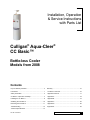
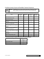
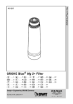
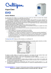
Cat. No. 01021819 Rev. O 12/31/08 DCO # 010916 Installation, Operation & Service Instructions with Parts List CULLIGAN® Aqua-Cleer® CC Basic™ Bottle-less Cooler ©2008 Culligan International Company Printed in USA Attention Culligan Customer: Your local independently operated Culligan dealer employs trained service and maintenance personnel who are experienced in the installation, function and repair of Culligan equipment. This publication is written specifically for these individuals and is intended for their use. We encourage Culligan users to learn about Culligan products, but we believe that product knowledge is best obtained by consulting with your Culligan dealer. Untrained individuals who use this manual assume the risk of any resulting property damage or personal injury. Culligan POU Coolers are combined with selected Culligan water treatment components to create a system specifically tailored to match the customer application. WARNING! Prior to servicing equipment, disconnect power supply to prevent electrical shock. NOTE This system is not intended for use where water is microbiologically unsafe or with water of unknown quality. WARNING! If incorrectly installed, operated or maintained, this product can cause severe injury. Those who install, operate, or maintain this product should be trained in its proper use, warned of its dangers, and should read the entire manual before attempting to install, operate, or maintain this product. Products manufactured and marketed by Culligan International Company (Culligan) and its affiliates are protected by patents issued or pending in the United States and other countries. Culligan reserves the right to change the specifications referred to in this literature at any time, without prior notice. Culligan, Aqua-Cleer, Culligan Man and www.culligan.com are trademarks of Culligan International Company or its affiliates. Culligan International Company 9399 West Higgins Road, Suite 1100 Rosemont, Illinois 60018 To Order Culligan Parts call: 1-800-428-2828 www.culliganindustrial.com www.culligancommercial.com WARNING! This device complies with part 15 of the FCC rules subject to the two following conditions: 1) This device may not cause harmful interference, and 2) This device must accept all intereference received including interference that may cause undesired operation. This equipment complies with Part 15 of the FCC rules. Any changes or modifications not expressly approved by the manufacturer could void the user’s authority to operate the equipment. Changes or modifications not expressly approved by the party responsible for compliance could void the user’s authority to operate the equipment. Installation, Operation & Service Instructions with Parts List Culligan® Aqua-Cleer® CC Basic™ Bottle-less Cooler Models from 2008 Contents Key Pre-Delivery Activities.................................................ii Warranty........................................................................... 15 Introduction........................................................................ 1 CC Basic™ Parts List...................................................... 16 Safety Information............................................................. 3 Appendix Overview......................................................... 17 CC Basic™ Inspection and Setup..................................... 4 Appendix A...................................................................... 18 Installing the CC Basic™................................................... 8 Appendix B...................................................................... 19 Sanitizing the CC Basic™............................................... 10 Appendix C...................................................................... 22 Descaling the CC Basic™............................................... 11 Appendix D...................................................................... 26 Troubleshooting............................................................... 13 Appendix E...................................................................... 29 Technical Specifications.................................................. 14 Cat. No. 01021819 Contents i Key Pre-Delivery Activities CAUTION! The cooler and the water treatment equipment must be properly prepared before the system is delivered to the customer. Aqua-Cleer® CC Basic™ Filter Systems Aqua-Cleer® CC Basic™ Filter—see Appendix A, Figure 5, on page 18. • Uses: sediment filter and carbon block filter in two (2) E-Z Change heads. Aqua-Cleer® CC Basic™ Reverse Osmosis Systems Aqua-Cleer® CC Basic™ RO—see Appendix B, Figure 8 on page 19. • Uses: carbon block and RO 50 cartridges in two (2) E-Z Change heads with storage tank and inline post carbon filler. • For detailed instructions about Aqua-Cleer® components please refer to the complete Installation, Operation and Service Manual, Cat. No. 01020219. Aqua-Cleer® CC Basic™ LC-100 RO—see Appendix C, Figure 13 on page 22. • Uses: Preferred Series 250 Filter and LC-100 RO with storage tank and inline post carbon filter. • For detailed instructions about Aqua-Cleer LC components please refer to the complete Installation, Operation and Service Manual, Cat. No. 01882074. Aqua-Cleer® CC Basic™ AC50 RO—see Appendix D, Figure 17 on page 26. • Uses: AC50 inline post carbon filter and storage tank. • For detailed instructions about AC 50 components please refer to the complete Installation, Operation and Service Manual, Cat. No. 01018587. Aqua-Cleer® CC Basic™ POU Cooler Inspection and Setup Procedures—see Appendix E on page 29. ii Culligan® Aqua-Cleer® CC Basic™ ii Cat. No. 01021819 Pre-Delivery Activity: Prepare and Flush Water Treatment Components CAUTION! All RO Membranes will require a 24-hour flush to drain. All flushing of membranes and filters must be done with chlorine-free, filtered, softened water. Activity Aqua-Cleer® CC Basic™ Filter Flush the filters to drain for at least five (5) minutes with filtered soft water c Aqua-Cleer® Aqua-Cleer® CC Basic™ RO CC Basic™ LC100 RO Aqua-Cleer® CC Basic™ AC50 RO Verify that system includes Automatic Shut-Off Valve (01021587) c c Verify that system includes Check Valve (01021588) c c Verify system includes Air Gap (44403001 or equivalent) for system drain c c c Flush the RO cartridge to a drain with filtered softened water for 24 hours prior to installation c c c Flush the carbon block filter to drain for at least five (5) minutes until there are no more carbon fines observed. c Activate the Preferred Series 250 cartridge and thoroughly flush per the detailed instructions c Flush the pre-carbon filter and sediment filters to drain c Flush the carbon post filter to drain c c c Sanitize and flush the storage tank c c c Pre-Delivery Activity: Prepare and Flush POU Cooler for Service Activity Aqua-Cleer® CC Basic™ POU Cooler Unpack the POU Cooler. c Inspect the POU Cooler for any shipping damage. c Flush and test the POU Cooler. c Cat. No. 01021819 Key Pre-Delivery Activities iii This page intentionally left blank. iv Culligan® Aqua-Cleer® CC Basic™ iv Cat. No. 01021819 Introduction The Culligan Aqua-Cleer® CC Basic™ system provides an economical solution to point-of-use water treatment systems in the marketplace. Unlike a bottled water cooler, incoming tap water is treated as it is needed, so the water is always fresh and great tasting. Best of all, there are no bottles to change and the supply is unlimited. The Culligan Aqua-Cleer® CC Basic™ dispenses both hot and cold water using selected filters or reverse osmosis technology depending on your needs and the incoming water supply. The Culligan Aqua-Cleer® CC Basic™ is shipped with empty EZ change single heads that will enable configurations for virtually any incoming water condition. You decide on the filtration package needed and then simply twist the filters selected into the EZ Aqua-Cleer filter heads behind the lower front panel. The Culligan Aqua-Cleer® CC Basic™ has been designed to facilitate the use of other Culligan filtration and RO options such as the AC-50 RO System and the LC-100 RO Membrane with Preferred Series Filter Systems. This publication is based on information available when approved for printing. Continuing design refinements could cause changes that may not be included in this publication. Cat. No. 01021819 Introduction 1 Safe Practices Throughout this manual there are paragraphs set off by special headings. Notice Notice is used to emphasize installation, operation or maintenance information which is important, but does not present any hazard. For example, NOTICE The nipple must extend no more than 1 inch above the cover plate. Caution Caution is used when failure to follow directions could result in damage to equipment or property. For example, CAUTION! Disassembly while under water pressure can result in flooding. Warning Warning is used to indicate a hazard which could cause injury or death if ignored. For example, WARNING! Electrical shock hazard! Unplug the unit before removing the timer mechanism or cover plates! The CAUTION and WARNING paragraphs are not meant to cover all possible conditions and situations that may occur. It must be understood that common sense, caution, and careful attention are conditions which cannot be built into the equipment. These MUST be supplied by the personnel installing, operating, or maintaining the system. Be sure to check and follow the applicable plumbing codes and ordinances when installing this equipment. Local codes may prohibit the discharge of sanitizing or descaling solutions to drain. Use protective clothing and proper face or eye protection equipment when handling chemicals or power tools. NOTE The Culligan Aqua-Cleer® CC Basic™ is not intended for use with water that is microbiologically unsafe or of unknown quality without adequate disinfection either before or after the system. NOTE Check with your public works department for applicable local plumbing and sanitation codes. Follow local codes if they differ from the standards used in this manual. To ensure proper and efficient operation of the Culligan Aqua-Cleer® CC Basic™ to your full satisfaction, carefully follow the instructions in this manual. 2 Culligan® Aqua-Cleer® CC Basic™ 2 Cat. No. 01021819 Safety Information Electrical Safety • Only connect the power cord to a 120V properly grounded outlet. • Never pull the power plug from the outlet with a wet hand or allow the plug to get wet. • Keep the power cord out of heavy traffic areas. • To avoid a fire hazard, never put the power cord under rugs, near radiators, stoves or heaters. • Do not use a damaged power cord or plug. If the power cord is damaged, a qualified service technician must replace it. • Do not use an extension cord with the CC Basic™. Installation and Usage Safety • Keep the CC Basic™ away from direct sunlight and excessive humidity. • Keep at least four (4) inches from the wall. • Do not lay the CC Basic™ down on its side. If for some reason the unit was placed on its side, it must stand upright for a minimum of two (2) hours before operation to allow the compressor to stabilize. • Connect the water supply to a cold water line only. Feed water over 105°F (40°C) can damage the filters. • Never install the system where it could freeze. • If the feedwater pressure is over the recommended operating pressure of 60 psi (4 bar), install a pressure-reducing valve in the water line. Be aware of pressure transients. • Filters should be replaced on schedule. Overused filters will deteriorate the performance of the system. • D rain the water out of the CC Basic™ after long periods of non-use, such as over the long weekend; this will allow a fresh batch of water to fill the system. Cat. No. 01021819 Safety Information 3 CC Basic™ Inspection and Setup Inspect the Unit NOTE All preparation work should be done in a clean area. A separate room is recommended. 1. Inspect the carton for evidence of shipping or handling damage. 2. Unpack the unit and inspect the plastic parts. Install Point of Use Assembly Kit—Part Number 01017703 1. On the CC Basic™ unit, remove the locking pin from the Crystal Guard. NOTE May require the use of a tool to remove pin. 2. Press on the Guard rim and turn counter clockwise to remove (Figure 1). Locking Pin Crystal Guard Open Figure 1. 3. Open the POU Kit box and check the assembly for damage. 4. Verify the float mounting pins are firmly inserted onto the float arm. 5. Ensure that both floats are positioned downwards. 6. Install the POU kit on the CC Basic™ unit (Figure 2). 4 Culligan® Aqua-Cleer® CC Basic™ 4 Cat. No. 01021819 Close Figure 2. 7. Position the ¼" tubing from the POU kit so that it exits from the rear of the cooler (Figure 3). Figure 3. 8. After installation of the POU kit, the RESET indicator should be located towards the rear of the unit (Figure 4). Cat. No. 01021819 CC Basic™ Inspection and Setup 5 Slide to reset After installation of the POU assembly, the reset indicator should be located towards the rear of the cooler Figure 4. Point of Use Kit Indicator Function The POU Kit is designed with two floats. The lower float shuts off the feed water to the reservoir when it lifts. The upper float is a safety float. If the first float should fail, the upper float will shut off the feed water AND LOCK the unit from further feed water until the reset switch is manually reset after troubleshooting the cause. The Check Indicator on the top of the POU kit (Figure 4) will normally be set to GREEN. It will change to RED indicating a lower valve failure or leak from tubing or fittings in the reservoir and lock. Determine the cause for the RED indicator before resetting indicator to the GREEN position. No more water will be allowed into the reservoir until the switch is manually reset to the GREEN position. Initial Sanitization 1. Connect a filtered feed water supply at 40-45 psi to the tubing at the rear of the unit (Figure 3). RO water is recommended. NOTE Prepare all filters, RO cartridges, and the RO storage tank strictly in accordance with the instructions included in the Appendix section of this manual. 2. Make sure the indicator is in the GREEN position. 3. Slowly turn on the feed water supply and fill the unit. NOTE It may take several minutes before the cold tank is full and water begins to flow from the dispensing head. Flush approximately 3 gallons (11 liters) of water through the cold tank. 4. Check that the lower float shuts off the feed water and the indicator remains GREEN. 5. Check for leaks. 6. Flush water through both faucets. 7. Plug in the unit and turn ON the Hot tank switch. 6 Culligan® Aqua-Cleer® CC Basic™ 6 Cat. No. 01021819 CAUTION! The unit is now live. Take suitable safety precautions. 8. Allow 45 minutes to reach full Hot and Cold temperatures. 9. Flush 1-2 gallons (4-8 liters) through each faucet. 10. Verify lower float allows filling and that the upper float will trip the indicator to RED. 11. Turn OFF the Hot tank and the feed water. 12. Unplug and drain the unit. 13. Remove the POU kit and Baffle Cup. 14. Add 1 tablespoon of liquid chlorine beach (5¼% sodium hypochlorite) to one gallon of RO water. 15. Pour sanitizer solution into reservoir. 16. Place baffle in solution and allow to stand for 5-10 minutes. 17. Use a clean cloth, paper towels or small brush to scrub all parts of the reservoir, floats, baffle cup and faucets. 18. Rinse all parts with filter water several times. 19. Replace baffle cup and refill the unit. NOTE It may take several minutes before the cold tank is full and water begins to flow from the dispensing head. Flush approximately 3 gallons (11 liters) of water through the cold tank. 20. Flush 1-2 gallons of fresh filtered water through the faucets until no chlorine is present. 21. Turn off the feed water and drain the unit. 22. Wipe down the unit and repackage for transport to the installation site. Cat. No. 01021819 CC Basic™ Inspection and Setup 7 Installing the CC Basic™ NOTE All personnel should be aware of company requirements for their own cleanliness and hygiene when installing, servicing or sanitizing a unit NOTE If the treatment components have remained in the unit for more than 24 hours since they were flushed and transported to a customer location, it is highly recommended that they get flushed to the drain before installing. Install a pressure regulator, if needed, on the incoming water supply line, set to 40-45 psi. The unit should not be exposed to direct sunlight, heat sources, or an ambient air temperature above 90°F (32°C) or below 37°F (3°C). ake sure there is adequate clearance around the unit to allow for heat dissipation of the condenser. M The warmer the environment is surrounding the unit, the more clearance that is required. A typical office install should require 2 inches of clearance all around the machine. Installs in factories, warehouses, and garages, where the ambient temperature is above 80°F, will require a minimum of 4 inches clearance. Install the Water Treatment System Components The water treatment system components are installed outside the CC Basic™ POU Cooler. See Appendix for typical treatment system types. Detailed instructions for the preparation and sanitization of treatment components are in Appendixes A, B, C, and D. Position the Unit 1. Locate the unit as close to the water supply and the electrical connections as possible. 2. Level the unit so the POU kit floats will work properly. 3. Check that the indicator is in the GREEN position. Establish the Water Connection 1. Flush the feed water tubing to the unit before making the connection to the ¼" tubing at the rear of the unit. 2. Connect the unit to the water. NOTE Do not turn on the power switches yet. 3. Slowly turn on the water supply. Check all connections for leaks. 4. Check that the water treatment system begins to fill the reservoir. 5. Once the reservoir fills, depress and hold the Hot button and verify that water dispenses from the faucet. NOTE Because it will take some time for the RO system to fill the reservoir, take along a few jugs of freshly prepared RO water from your shop to fill the reservoir for the first time. 6. Depress and hold the Cold dispense button until water dispenses from the faucet. 7. Plug the unit into a power supply. CAUTION! The unit is now live. Take suitable safety precautions. 8. Turn ON the Power Switch to start the chilling and heating processes. 8 Culligan® Aqua-Cleer® CC Basic™ 8 Cat. No. 01021819 9. Verify that the compressor and heater are both working. This is best accomplished by placing a hand on top of the compressor to feel for vibration, and by dispensing water from the hot tank (after five minutes) noting a temperature increase in the water. 10. T aste the water. Check the unit is clean and functions to the customer’s satisfaction. If you are not satisfied with the quality of the water, check the filters and flush additional water through the unit. 11. Prior to leaving the unit, answer any customer questions about the operation of the CC Basic™ POU cooler. Cat. No. 01021819 Installing the CC Basic™ 9 Sanitizing the CC Basic™ NOTE The CC Basic™ model must be sanitized every 12 months, when taste concerns arise, or after boilwater alerts are lifted. Units in dusty or high-use locations may need more frequent servicing. All personnel should be aware of company requirements for their own cleanliness and hygiene when servicing and sanitizing a unit. Latex gloves must be used when handling the filters, UV bulb, quartz sleeve or any components that have contact with the drinking water. Prepare the CC Basic™ for Sanitization 1. Turn OFF the Hot tank and the feed water line. 2. Unplug and drain the unit. 3. Remove the POU kit and the Baffle Cap. Sanitize the Unit 1. Add 1 tablespoon of liquid chlorine beach (5¼% sodium hypochlorite) to one gallon of RO water. 2. Pour sanitizer solution into reservoir. 3. Place baffle in solution and allow to stand for 5-10 minutes. 4. Use a clean cloth, paper towels or small brush to scrub all parts of the reservoir, floats, baffle cup and faucets. 5. Rinse all parts with filter water several times. 6. Replace baffle cup and POU kit. 7. Make sure the indicator is in the Green position. 8. Turn on the feed water and refill the unit. Flush and Return Unit to Service 1. Flush 2–4 gallons (8–11 liters) of fresh filtered water through the faucets until no chlorine is present. 2. Turn off the feed water and drain the unit completely. 3. Refill the unit with fresh water from the water treatment system. 4. Plug in the unit and turn ON the Hot tank switch. CAUTION! The unit is now live. Take suitable safety precautions. 5. Verify that the compressor and heater are working. 6. Taste the water. Check the unit is clean and functions to the customer’s satisfaction. If you are not satisfied with the quality of the water, check the filters and flush additional water through the unit. 7. Wipe down the unit, clean the area, and answer any customer questions. 10 Culligan® Aqua-Cleer® CC Basic™ 10 Cat. No. 01021819 Descaling the CC Basic™ CC Basic™ units using an RO configuration should rarely need to be descaled. A unit with the hot water option may require removing any calcium build-up inside the hot tank, depending on local water conditions and the type of water treatment. All personnel should be aware of company requirements for their own cleanliness and hygiene when servicing and sanitizing a unit. Latex gloves must be used when handling the filters, UV bulb, quartz sleeve or any components that have contact with the drinking water. Prepare the CC Basic™ Unit for Descaling 1. Turn OFF the Hot tank and the feed water line. 2. Unplug and drain the unit. CAUTION! Drain water will be hot! 3. Remove the POU kit and the Baffle Cap. Descale the Hot Tank 1. Mix 1 bag of ScaleKleen (7 oz. bag of non-toxic citric acid-based descaler, Innowave part no. 01-2076) with 1 gallon of hot RO water in a separate container or pitcher. Stir well. NOTE Add red or green food coloring to the solution, in order to make it easier to tell when the solution is completely flushed from the unit. 2. Pour the solution into the reservoir and allow the solution to fill the Hot tank. 3. Fill the reservoir the rest of the way with RO water. 4. Plug in the unit and turn ON the Hot tank switch. CAUTION! The unit is now live. Take suitable safety precautions. 5. Allow the solution in the Hot tank to heat for 5–10 minutes. 6. Turn OFF the Hot tank and unplug the unit. 7. Allow the solution to sit in the hot tank for an additional 10–20 minutes. 8. Drain the unit through the hot tank. CAUTION! Drain water will be hot! 9. Replace the drain plug. Cat. No. 01021819 Descaling the CC Basic™ 11 10. Slowly turn ON the feed water supply and refill the unit. 11. Drain the Hot tank and continue to flush for another five minutes. 12. Check that no food coloring remains in the rinse water. 13. Turn OFF the feed water and drain the unit completely. Flush and Return the Unit to Service 1. Replace the Baffle Cup and POU kit. 2. Make sure the indicator is in the GREEN position. 3. Turn ON the feed water and refill the unit. 4. Refill the unit with fresh water from the water treatment system. 5. Flush water through both faucets. 6. Plug in the unit and turn ON the Hot tank switch. CAUTION! The unit is now live. Take suitable safety precautions. 7. Verify that the compressor and heater are working. 8. T aste the water. If you are not satisfied with the quality of the water, check the water treatment system and flush additional water through the unit. 9. Wipe down the unit, clean the area, and answer any customer questions regarding use of the unit. 12 Culligan® Aqua-Cleer® CC Basic™ 12 Cat. No. 01021819 Troubleshooting NOTE Fault finding must only be carried out by trained personnel. Symptom Possible Cause NO FLOW OF WATER Solution 1. Make sure that there is a water supply to the unit and that it is turned on. 2. If an anti-flood or leak detection device is installed, please check and reset if necessary. 3. For units with EZ heads, ensure that the filter is twisted all the way into the head; otherwise the valve inside the filter head will not be opened. 4. Check to see that the filter is not blocked with sediment. THERE IS FLOW FOR THE HOT WATER, BUT NO FLOW FOR THE COLD WATER This may be a result of the water inside the cold tank mechanism being frozen. 1. Verify that the thermostat is set at the factory setting. 2. Unplug the unit and allow the ice inside the cold tank to melt. WATER DISPENSED BY THE UNIT IS NEITHER HOT NOR COLD 1. Make sure that the power switch and the Hot tank are turned on at the back of the unit. THE POWER IS NOT ON 1. Make sure that the unit is plugged in correctly and that the power switch is on. 2. Check the fuse on the back of the unit BAD TASTE 1. Flush the unit for a period of 15 minutes. 2. If the bad taste persists, taste the water coming directly from the filter; if still bad change the filter, or contact your authorized service provider. LOW FLOW OF COLD WATER If this happens in the cold water circuit, there may be a problem with freezing. Please refer to “There is flow for the hot water, but no flow for the cold water.” LOW FLOW OF WATER FOR ALL CIRCUITS OF THE UNIT The filter may require changing, or there is low water supply pressure. Ensure that the filter is not blocked. LOW FLOW OF HOT WATER Indicates that the hot tank needs to be de-scaled. Cat. No. 01021819 Troubleshooting 13 Technical Specifications Item Width/Depth/Height Specification 12.4"x12.8"x38.8" (315mmx325mmx985 mm) Water Connection 1/4" Tubing Cold Tank Capacity 0.9 Gallons (3.5 Liters) Hot Tank Capacity 1.2 Gallons (4.5 Liters) Hot Tank Temperature 167F to 198F(75C to 99C) Recommended Service Pressure 40-45 PSI (3.1 Bar) Maximum Service Pressure 50 PSI (3.4 Bar) Rated Service Flow 0.5 GPM (1.89 LPM) Temperature Rating 50-100 F (10 - 37C) Refrigerant R134a Refrigerant Charge 1.0 Oz (28.4 gm) Weight 27.5 Lbs (12.5 Kg) Electrical Supply 120V / 60 Hz Compressor 74 Watts Heater 450 Watts System 6.2 Amps End of Life At the end of this product’s life, please ensure that it is disposed of in an environmentally friendly manner that is fully compliant with your Country requirements/guidelines. 14 Culligan® Aqua-Cleer® CC Basic™ 14 Cat. No. 01021819 Warranty Limited Warranty for the CULLIGAN® Aqua-Cleer® CC Basic™ Water Treatment System Culligan International Company (CULLIGAN) warrants the water cooler, when installed and operated in accordance with the installation instructions, against defects in material and workmanship under normal use as follows: Three (3) years from the date of installation or 42 months from date of shipment from the factory, whichever occurs first, CULLIGAN at their option will repair or replace any defective parts. In addition, after the three-year warranty, CULLIGAN warrants the hermetically sealed refrigeration system, including the compressor, evaporator, condenser, filter-drier, and refrigerant line, to be free from defects in material and workmanship under normal use for an additional two (2) years. The hot tank casing, electrical wiring and components are covered fro the standard three-year or 42-month warranty as stated above. This warranty does not cover damage due to accident, freight damage, misuse, abuse, and negligence; fouling of components due to liming, dirt, unsatisfactory water conditions, or faulty plumbing. CULLIGAN does not accept responsibility for personal injury resulting from misuse of equipment. Field service calls to replace or install parts, adjust water stream, or temperature; unauthorized service work and finish deterioration due to normal use cannot be claimed under this warranty. when the water cooler is located within Canada and the United States, CULLIGAN’s obligation is limited to providing a replacement part or repairing of the water cooler, which upon examination, is found to be defective in workmanship or material. Claims will not be accepted if serial nameplate is mutilated or removed. This warranty includes freight by the most economical means to the nearest service center, if after examination, is found to be defective due to workmanship or material. Customer should not send coolers or parts without authorization from CULLIGAN. When the water cooler is located outside Canada or the United States, CULLIGAN’s obligation is limited to providing for one year replacement part for any part expressly covered by this warranty, but does not include any obligation to provide labor or to pay labor costs incurred in connection with the replacement. It includes the cost of outbound freight (excluding express freight) or part(s) to the nearest port in Canada, from which the part(s) are shipped to their ultimate destination. Except as set forth herein, CULLIGAN makes no other warranty, guarantee or agreement expressed, implied or statutory, including any implied warranty of merchantability or fitness for a particular purpose. In no event will CULLIGAN be liable for special or consequential damages or any delay in the performance of this agreement due to causes beyond their control. All implied warranties, including without limitation warranties of merchantability and fitness for a particular purpose, are limited in duration to the period in this limited warranty. If a part described above is found defective within the specified period, you should notify your independently operated Culligan Dealer and arrange a time during normal business hours for the dealer to inspect the water cooler on your premises. Any part found defective within the terms of this warranty will be repaired or replaced by the dealer. You pay only freight from our factory and local dealer charges. The customer acknowledges that water, like other liquids, can cause damages to surfaces. Customer takes full responsibility for placing the cooler within a residence or business, and acknowledges that any failure to address drips, leaks, or spills is at the customer’s own risk. Cat. No. 01021819 Warranty 15 Appendix E Inspection and Setup Procedures Inspect the Unit NOTE All preparation work should be done in a clean area. A separate room is recommended. 1. Inspect the carton for evidence of shipping or handling damage. 2. Unpack the unit and inspect the plastic parts. Install Point of Use Assembly Kit – Part Number 01017703 1. On the CC Basic™ unit, remove the locking pin from the Crystal Guard. NOTE May require the use of a tool to remove pin. 2. Press on the Guard rim and turn counter clockwise to remove (Figure 18). Crystal Guard Locking Pin Open Figure 18. 3. Open the POU Kit box and check the assembly for damage. 4. Verify the float mounting pins are firmly inserted onto the float arm. 5. Ensure that both floats are positioned downwards. 6. Install the POU kit on the CC Basic™ unit (Figure 19). Cat. No. 01021819 Appendix E 29 Close Figure 19. 7. Position the ¼” tubing from the POU kit so that it exits from the rear of the cooler (Figure 20). Figure 20. 8. 30 Culligan® Aqua-Cleer® CC Basic™ 30 Cat. No. 01021819 9. After installation of the POU kit, the RESET indicator should be located towards the rear of the unit (Figure 21). Slide to reset After installation of the POU assembly, the reset indicator should be located towards the rear of the cooler Figure 21. Point of Use Kit Indicator Function The POU Kit is designed with two floats. The lower float shuts off the feed water to the reservoir when it lifts. The upper float is a safety float. If the first float should fail, the upper float will shut off the feed water AND LOCK the unit from further feed water until the reset switch is manually reset after troubleshooting the cause. The Check Indicator on the top of the POU kit (Figure 4) will normally be set to GREEN. It will change to RED indicating a lower valve failure or leak from tubing or fittings in the reservoir and lock. Determine the cause for the RED indicator before resetting indicator to the GREEN position. No more water will be allowed into the reservoir until the switch is manually reset to the GREEN position. Initial Sanitization 1. Connect a filtered feed water supply at 40–45 psi to the tubing at the rear of the unit (Figure 3). RO water is recommended. NOTE Prepare all filters, RO cartridges, and the RO storage tank strictly in accordance with the instructions included in the Appendix section of this manual. 2. Make sure the indicator is in the GREEN position. 3. Slowly turn on the feed water supply and fill the unit. NOTE It may take several minutes before the cold tank is full and water begins to flow from the dispensing head. Flush approximately 3 gallons (11 liters) of water through the cold tank. 4. Check that the lower float shuts off the feed water and the indicator remains GREEN. 5. Check for leaks. 6. Flush water through both faucets. Cat. No. 01021819 Appendix E 31 7. Plug in the unit and turn ON the Hot tank switch. CAUTION! The unit is now live. Take suitable safety precautions. 8. Allow 45 minutes to reach full Hot and Cold temperatures. 9. Flush 1-2 gallons (4-8 liters) through each faucet. 10. Verify lower float allows filling and that the upper float will trip the indicator to RED. 11. Turn OFF the Hot tank and the feed water. 12. Unplug and drain the unit. 13. Remove the POU kit and Baffle Cup. 14. Add 1 tablespoon of liquid chlorine beach (5¼% sodium hypochlorite) to one gallon of RO water. 15. Pour sanitizer solution into reservoir. 16. Place baffle in solution and allow to stand for 5-10 minutes. 17. Use a clean cloth, paper towels or small brush to scrub all parts of the reservoir, floats, baffle cup and faucets. 18. Rinse all parts with filter water several times. 19. Replace baffle cup and refill the unit. NOTE It may take several minutes before the cold tank is full and water begins to flow from the dispensing head. Flush approximately 3 gallons (11 liters) of water through the cold tank. 20. Flush 1-2 gallons of fresh filtered water through the faucets until no chlorine is present. 21. Turn off the feed water and drain the unit. 22. Wipe down the unit and repackage for transport to the installation site. 32 Culligan® Aqua-Cleer® CC Basic™ 32 Cat. No. 01021819 Cat. No. 01021819 Appendix E 33