1
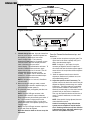
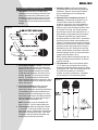
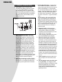
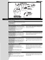
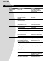
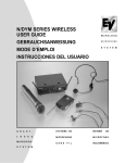
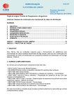
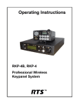
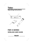
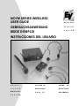
N/DYM SERIES WIRELESS
USER GUIDE
GEBRAUCHSANWEISUNG
MODE D’EMPLOI
INSTRUCCIONES DEL USUARIO
WIRELESS
MICROPHONE
S Y S T E M
D R A H T -
SYSTEME DE
SISTEMA
L
MICROPHONE
MICRÓFONO
S A N S
INALÁMBRICO
O
S
E
S
MIKROFONS Y S T E M
F I L
DE
ENGLISH
Table of Contents
1. Quick System setup guide
2. System Description
3. Detailed system/component setup instructions
3.1 Receiver Setup & Operation
3.2 Handheld Transmitter Setup
3.3 Beltpack Setup
4. Guidelines/Recommendations for best performance
5. Troubleshooting Guide
6. Technical Specifications
7. Certifications
8. Components & Accessories
9. Service/Warranty
1. Quick System Setup Guide
Receiver Setup
1. Plug power supply cord into the back of the receiver and plug the power supply into an outlet. The
channel display & red/green “Diversity” light on the
receiver front panel should light up.
2. Depress “SET” button on front panel and release
when channel display starts to flash (about 3
seconds). This activates “ClearScanTM” to find an
interference free channel for operation. Note the
channel (0 - 9) shown on the receiver front panel
channel display.
3. Connect receiver audio output to mixer (or
amplifier if using guitar system). Mute or reduce
mixer/amp gain.
4. Orient receiver antennas angled up and away from
each other (at a 90 degree angle).
Transmitter Setup
1. Open battery compartment, install 9 Volt battery.
Make sure to observe proper battery polarity.
2. Adjust channel setting to match channel number
shown on receiver channel display. Replace
battery cover.
3. If using beltpack transmitter, plug the microphone
into the transmitter connector. If using guitar
system, connect 1/4” plug into guitar.
Operating the system
1. Turn transmitter ON via the ON/OFF switch.
Yellow “Tx On” light should illuminate on the receiver front panel.
2. Turn audio switch to the ON position to unmute the
audio.
3. Set mixer/amp gain to normal position.
4. Talk/sing into the microphone or play the guitar at a
normal volume. You should hear audio coming out
of the system.
5. If the signal is distorted, turn the gain adjust control on the transmitter down. If the signal level is
low, you may need to turn the gain adjust control
up.
6. If connected to the receiver 1/4” output jack on the
front panel, adjust gain (via the control next to the
connector) to correspond to the signal level found
when singing or playing through a wired system.
ENGLISH
2. System Description
The Electro-Voice N/DYM Wireless is a series of 10 channel frequency agile UHF wireless systems that combine
EV’s legendary quality and reliability with high value. The N/DYM Series transmitters and receivers operate in the
UHF frequency range on one of ten channels between 800 and 814 MHz. The well-designed audio circuitry
ensures excellent signal-to-noise ratio with accurate sound quality.
System Features
• 10 Channel Frequency Agile UHF system operation.
• Featuring “ClearScanTM” which makes for quick and
easy system setup.
• Handheld transmitters feature EVs’ N/DYM mic
elements, for superior sound quality.
• True-diversity system with Secure-PhaseTM ensures
maximum range and freedom from interference.
• Well-designed companding and audio circuitry
insures high signal-to-noise ratio and excellent
sound quality.
• Choice of two handheld and four bodypack
systems, including a system specifically for guitar.
• Permanently attached antennas make setup quick
and easy.
• Receivers may be rack-mounted with optional kit.
• Audio output via 3-pin XLR-type balanced mic level
and 1/4-inch unbalanced line level connectors.
3 Detailed Setup Instructions
3.1 Receiver Setup & Operation
1. Place the receiver where there is a clear line of
sight to the area where the transmitter will be
used. Rotate the receiver’s antennas and
separate them 90 degrees (see Figure 1).
2. Connect the power supply cord to the receiver.
Plug the power supply into an AC outlet Confirm
that the receiver is ON by checking for the lit
red/green Diversity light and channel
display on the front panel.
NOTE: Upon power-up, the receiver will return to
the channel it was set to when it was turned off.
CAUTION: Please make sure that the AC
adapter is the correct voltage for your local
requirements.
TM
3 ClearScan : The N/DYM Wireless system features ClearScanTM. ClearScanTM automates the
process of finding a clear channel to use in setup
of your N/DYM Wireless system. To use
ClearScanTM, depress and hold down the set button for 3 seconds. When the channel display
begins flashing release the set button. The receiver is now searching for a clear frequency, by
measuring the RF energy present on each channel. The entire process will take about 5 seconds.
While scanning, the channel display will show the
channel number being scanned. When
ClearScanTM is complete, the display will stop
flashing and it will display the number of the channel recommended for use.
NOTE: If using more than one N/DYM system, set
up ONE system at a time. Turn on the transmitter
for the first system, before using ClearScanTM to
set up the second. Please see the “Guideline/
Recommendations for best performance” section
to setup more than two systems.
4. Setting the channel. Changing the channel on
the receiver can also be done manually. By
momentarily depressing the Set button, the
channel number is increased by one.
NOTE: When the system is turned off, the
channel number is saved in non-volatile memory.
When the receiver is turned on, it will return to the
same channel number.
ENGLISH
Figure 1. Front View
Figure 2. Rear View
5.
Channel change lock-out. Once the channel has
been set on the receiver, the N/DYM system has
the capability to deactivate or lock-out the
channel change button. This is done by
depressing the set button for 10 seconds or more.
Lock-out is active when the decimal point illuminates in the lower right corner of the
channel display. This will defeat the set button. To
override or defeat the lockout function, again
depress the set button for 10 seconds. This will
reactivate the channel set button to work
normally. This function can be useful when the
wireless is in a location where unauthorized personnal have access to the receiver.
NOTE: If the system is in “lock-out”, ClearScanTM
will not function.
6. Make sure the gain setting is muted or turned
down on the mixer channel or amplifier input you
will connect the wireless system to.
7. Plug the audio cable (not supplied) into either output connector.
NOTE: The 3-pin XLR-type connector is the
preferred choice since the output is balanced.
Either connector may be used with good results. If
the 1/4-inch connector is being used, turn the
volume level control (see Figure 1) on the front
panel to the twelve o’clock position (midway in the
control’s range).
NOTE: The 3-pin XLR-type connector output level
is fixed, and cannot be adjusted.
Now refer ahead to details on how to set up the
transmitter.
Once the Transmitter has been set-up, and
turned on….
8. Speak into the microphone or play the guitar. Turn
up the level on the mixer or preamp until you’re
able to hear the desired signal.
NOTE: If using the 1/4” jack output, It may be
necessary to adjust the receiver’s output until
the volume level from the wireless system approximates the level of an equivalent wired microphone
or instrument.
9. “Walk” the expected area of use to check for
dropouts or interference. If problems occur, see
the troubleshooting section.
10. Adjust the squelch control if necessary. The
squelch control on the back of the receiver may be
adjusted to effectively increase range or to reduce
interference. The factory setting is at a midpoint,
which should be suitable for most situations. To
effectively increase range, turn the control counterclockwise until you hear noise or interference.
Then, turn the squelch clockwise until the noise is
muted. To reduce interference, turn the control
clockwise.
NOTE: If the squelch is being adjusted, the transmitter should be turned off.
Caution! Increasing the range will make the
system more susceptible to outside interference! Reducing interference will also effectively decrease the range, which will make the system more susceptible to dropouts.
ENGLISH
3.2 Handheld Transmitter Setup
1. Insert battery. Slide open the hinged battery
compartment cover by placing your thumb on the
indents of the battery door (at the bottom of the
transmitter) and gently pushing down (see Figure
3). Insert the battery, terminal end first, into the
compartment, with the smaller positive terminal to
the right.
Figure 3.
5. Unmute the audio by sliding the audio switch
(immediately below the mic element) towards the
windscreen. Speak or sing into the microphone
and you should hear your voice through the
PA / sound system.
6. Adjustment of the transmitter audio gain - if
necessary. The transmitter audio gain is set to
a mid level which should be suitable for most
situations. However, for loud or soft speakers or
singers, an adjustment may be necessary. First,
speak or sing into the microphone and listen closely. If the gain is too high, you will hear distortion,
and if the gain is too low, the signal will be low. In
either situation, an adjustment may be necessary.
To adjust the transmitter gain, gently insert the
provided screwdriver (or other 3/32-in. screwdriver)
into the hole near the head of the transmitter (see
Figure 4). Turn lightly until the screwdriver tip drops
into the slot in the level control. Gently turn counterclockwise until the control stops (the mic output is
attenuated but not “off”). Slowly turn the mic-level
control up while listening to the audio. If the audio
becomes distorted, turn the mic level control down
(counter-clockwise) about 1/8 turn.
NOTE: Operate with the transmitter audio gain set
as high as possible without distortion, for the best
signal to noise ratio.
2. Set handheld transmitter channel to match the
channel setting on the receiver (channel number
displayed on front of receiver panel). The channel
setting on the handheld transmitter is accessed
through the round opening on the side of the mic
housing. Numbers 0 - 9 are printed around the
opening. The channel setting is determined by
which number the arrowed slot is pointing to. Use a
small screwdriver (supplied) to change the channel
setting. See Figure 4.
3. Turn on the transmitter by sliding the power
switch (closest to the battery compartment)
forward to the ON position (toward the windscreen).
The red battery condition light should flash once
and then go out. If the red light stays on or illuminates during a performance, the battery should be
replaced immediately. The green light will stay lit
when the handheld transmitter is on.
NOTE: Remember to turn the transmitter OFF
when not in use. This will conserve battery life.
4. Verify reception. When the transmitter is turned
on, the yellow “Tx On” light, located on the front
panel of the receiver, will illuminate, indicating that
the receiver is picking up the signal. If this does
not happen, make sure that the transmitter and
receiver are set to the same channels.
7. Test performance. Check to see that the yellow
“Tx On” light on the front panel of the receiver is
illuminated, an indication that the receiver is picking
up the signal. Then, “walk” the intended area of use
and make sure that there are no barriers to
reception or sources of interference. If problems
are encountered, see Troubleshooting Guide.
Figure 4.
ENGLISH
3.3 Bodypack Transmitter Setup
1. Insert battery. Open the hinged battery
compartment by placing your thumb or finger
on the indent labeled OPEN on the battery
door and pushing down, see Figure 6. When
inserting the battery, pay attention to the polarity (+/-) and insert the terminals into the battery
compartment first. Close the battery door by
sliding the door shut.
5. Connect the audio source. If using a lavalier or headworn microphone, insert the connector on the end of the mic wire, into the connector on the Bodypack. If using a lavalier
mic, use the clip to attach the mic to the users
clothing. If using the headworn mic, place the
headset on the user’s head, positioning the
mic at the corner of their mouth. If using a guitar system, connect the 1/4” plug into the instrument.
NOTE: Keep the audio muted while plugging in and adjusting the microphone or
source. Placement of lavalier and headworn
microphones will noticeably change the sound
quality, so some testing with the user is necessary. An important point to remember, the
closer to the sound source, the stronger or
louder the signal.
Figure 5.
2. Set the transmitter channel to match the
channel setting on the receiver. The channel
switch on the bodypack is located just underneath the battery door, and to the right of the
indent labeled OPEN. Note the channel number label (0-9) surrounding the opening. The
Bodypack channel must be set to the same
number as the receiver channel, which is displayed on the receiver front panel. The channel setting is determined by which number the
arrowed slot is pointing to. Use a small screwdriver (supplied) to change the channel setting.
3. Turn on the transmitter by sliding the power
switch to its on position. Check the condition of
the battery by watching the light below the
power switch. The red battery light should flash
once and then go out. If the light stays on, the
battery is weak and should be replaced.
4. Verify that the transmitter is sending. Observe
that the yellow Tx On light on the front panel of
the receiver is lit, an indication that the receiver is picking up the signal from the transmitter.
6.
Unmute the audio, by sliding the large
AUDIO switch located on the Bodypack, to
the ON position. Speak or sing into the
microphone and you should hear your voice
through the PA / sound system.
7.
Listen carefully to the audio and be sensitive of overload distortion and low gain.
8.
Adjust the transmit gain if necessary.
Gently insert the provided screwdriver or
other 3/32-in. (2.5 mm) screwdriver into the
gain adjustment located at the top edge of
the battery compartment under the door. The
door has to be opened but not swung upward
to make adjustments. Turn lightly until the
screwdriver tip drops into the slot on the level
control. Gently turn the control counterclockwise until the control stops (the audio output
is attenuated but not “off”). Slowly turn the
audio level control clockwise while listening
to audio; if the audio becomes distorted, turn
the mic level control counter-clockwise about
1/8 turn.
9.
Check reception by observing that the yellow Tx On light is lit on the receiver’s front
panel.
10. Clip the bodypack to the user’s belt, pocket, or guitar strap. The bodypack can be
positioned horizontally or vertically by moving
the belt clip attachment. This is done by
removing the belt clip attachment screw,
rotating the clip to the desired position, and
replacing the screw.
ENGLISH
Figure 6.
4 Guidelines/Recommendations for best performance
Compatibility
The receiver and transmitter must be set to the same channel
to operate together.
Using Multiple Wireless Systems
If two or more N/DYM Wireless and/or other VHF/UHF wireless systems are being used in the same location, proper frequency coordination is necessary to avoid interference. The
following N/DYM System channels will work together:
Contact your dealer or Electro-Voice for assistance, if you are
planning to add more wireless systems to be operated simultaneously in the same location.
Channels 0,1,2,3, & 4 or Channel 5,6,7,8, & 9
Multiple System Setup & ClearScanTM
ClearScanTM is most useful for finding operating frequencies for situations where no more than 2 systems
will be used simultaneously. When setting up more
than 2 systems, use ClearScanTM to choose the first
channel of operation. Set up subsequent systems following the channel groupings listed above in the “Using
Mulitple Wireless Systems” section.
Potential Sources of Interference
There are many potential sources of interference for your
wireless system. Any electronic product that contains digital
circuitry including digital signal processors (reverb/multieffects units), electronic keyboards, digital lighting controllers,
CD players and computers, all emit RF energy that can
adversely affect the performance of your wireless system. It
is always best to place your receiver as far away from these
devices as possible to minimize this potential source of problems.
Battery Recommendations
Fresh 9-volt alkaline batteries from a quality
manufacturer will yield the best performance from
your N/DYM transmitters. Rechargeable 8.4-volt
Ni-cad batteries can be used, but will yield much shorter
operational time.
the light does not flash or stays lit continuously, the battery is
weak or dead. If the light comes on during use, the battery is
weakening and should be replaced as soon as possible.
If sound quality degrades during use, it may be the result of a
weakening battery.
When the transmitter switch is turned on, the red
battery light will flash once if the battery is good. If
Receiver and Antenna Placement
Do not place the receiver near a large metal
object or surface.
Locate the receiver as close as possible to the area where
the Transmitter user will be working. Ideally, position the
receiver so that the transmitter is within site of the receiver.
When using multiple systems, do not allow antennas to cross
or touch each other.
ENGLISH
5 Troubleshooting Guide
Problem
Possible Causes
Solutions
No audio & no lights
on receiver
Receiver is off
Make sure that power supply is
properly connected and providing
power to the receiver.
No audio & no Tx ON
light on receiver
Transmitter is off.
Turn on transmitter power switch.
No ( or dead ) battery in
transmitter.
Insert fresh battery in transmitter.
Faulty battery contacts in
transmitter.
Clean contacts.
Transmitter audio switch
is off (signal is muted).
Turn on transmitter audio switch.
Receiver audio cable is damaged
or disconnected.
Connect, repair, or replace cable.
Gain not sufficient on mixer/
preamp/amp input.
Increase mixer/preamp/amplifier
gain setting.
Gain set too low (or muted) on
mixer/preamp/amplifier.
Increase gain setting on mixer/
preamp/amplifier.
Receiver audio too low (1/4” output).
Increase receiver audio volume setting.
Transmitter audio level too low.
Increase transmitter audio gain setting.
Transmitter audio level too high
(overloading transmitter circuit)
Decrease transmitter audio gain setting.
Receiver audio set too high
(1/4” output).
Decrease receiver audio level setting.
Battery level low in transmitter.
Insert fresh battery in transmitter.
Another wireless product in the
immediate area, operating on the
same frequency, or on a frequency
that mixes with another RF signal
(such as a TV broadcast transmitter).
Change operating frequency. If
interference is weak, keep transmitter
on at all times (to override interfering
signal) whenever receiver is on.
Receiver placed too close to a digital
signal processor or similar device.
Move receiver to a different location.
Strong electromagnetic field from
stage lighting or other source near
the transmitter or receiver, which may
be producing RF noise on or near the
operating frequency.
Change operating frequency. Repair or
remove source of interference. Move
receiver to a different location.
RF reflective metal obstacles
between transmitter & receiver.
Move the obstacles, or reposition the
receiver.
Poorly oriented beltpack antenna.
Reorient bodypack so that antenna is
positioned vertical (up and down) and
facing receiver, if possible.
Faulty receiving antenna system.
Reposition antennas or receiver.
No audio
Low audio signal.
Distorted audio signal.
Interference
Short range or drop-outs.
ENGLISH
6 N/DYM Wireless Series System Technical Specifications
UHF Receivers: NRU and NRU-G Receivers
Receiver Type
Synthesized PLL
Frequency Range (RF)
Between 800 - 814 MHz
Number of Selectable Channels
10
Diversity
True Diversity with Secure-PhaseTM
RF Sensitivity
< .8 uV for 12 dB SINAD
FCC Data
Approved under part 15
Audio Output,
Frequency Response
50 – 15 kHz +/- 2 dB
Audio Output, Balanced (XLR)
-20 dBV (600 Ohm Load)
Audio Output, Unbalanced (1/4")
adjustable 8 mv to 0.775V RMS (100 K ohm load)
Distortion
Less than 0.5%
Signal-to-Noise Ratio
>94 dB
Dynamic Range
100 dB
UHF Transmitters: NBPU, NBPU-G, NHTU-N1, NHTU-N2
RF Frequency Range
Between 800 - 814 MHz
Number of Selectable Channels
10
Radiated RF Output
10-15 mW typical
Microphone Element NHTU-N1 handheld
EV N/D 167 cardioid N/DYM dynamic
Microphone Element NHTU-N2 handheld
EV N/D 267a cardioid N/DYM dynamic
Standard Bodypack Microphones
Lavalier: (NRU-L10 system)
(NRU-L20 system)
Headset: (NRU-H1 system)
TA4F Connector Wiring:
EV OLM10 omni-directional condenser
EV ULM20 cardioid condenser
EV HM2 cardioid condenser
Pin 1: Ground; Pin 2: Mic Input;
Pin 3: +5 volt bias; Pin 4: +5 volt bias fed
through a 3 K ohm resistor for 2-wire electrets
Audio Gain Adjustment Range
40 dB
Battery Life
8 – 10 hours with 9-Volt alkaline
Bodypack Antenna
flexible external 1/4 wave
Handheld Mic Antenna
internal 1/2 wave
Size (Handheld transmitter)
26 cm (10.25 in) long
Size (Bodypack transmitter) HxWxD
4.5 in x 2.6 in x 1.25 in (no antenna)
114 x 66 x 32 mm
ENGLISH
7 Certifications
CERTIFICATIONS
NRU, NRSCU, Certified to ETS 300 445, Conforms to European Union directives, eligible to bear CE marking.
NHTU, NBPU, Certified to I-ETS 300 442 and ETS 300 445, Conforms to European Union directives, eligible to
bear CE marking.
Licensing of Electro-Voice equipment is the user’s responsibility and license eligibility depends on the
user’s classification, and frequency selected. Changes or modifications made by the user could void the
user’s authority to operate the equipment.
8. Accessories & Parts
Order #:
Description
450131
OLM10
450563
300059000
ULM20
879155
879156
HM2
450124
71081001
71081002
730139
730140
730103
Plastic clip for bodypack
Omni lavalier mic w/windscreen and clip
Windscreen for OLM10
Clip for OLM10
Unidirectional lavalier mic w/ windscreen and clip
ULM20 windscreen
ULM20 clip
Unidirectional headset condenser mic
Spring-adjusted mic stand adapter
Rack-mount kit - Single
Rack-mount kit - Double
120-volt power supply
(US/Canada type)
230-volt power supply
(EURO type)
230-volt power supply
(UK type)
ENGLISH
9. Service/Warranty
Factory Service
If factory service is required, ship the unit prepaid in its original carton to:
Telex EVI Audio GmbH
Hirschberger Ring 45
D-94315 Straubing
Telephone: +49 (0) 9421 706 0
Fax: +49 (0) 9421 706 350
Enclose a note describing the problem along with any other pertinent information.
Warranty (Limited)
Electro-Voice products are guaranteed against malfunction due to defects in materials or workmanship for a specified period, as noted in the individual product-line statement(s) below, or in the individual product data sheet or
owner’s manual, beginning with the date of original purchase. If such malfunction occurs during the specified period, the product will be repaired or replaced (at our option) without charge. The product will be returned to the customer prepaid.
Exclusions and Limitations: The Limited Warranty does not apply to: (a) exterior finish or appearance;
(b) certain specific described in the individual product-line statement(s) below, or in the individual product data
sheet or owner’s manual; (c) malfunction resulting from use or operation of the product other than as specified
in the product data sheet or owner’s manual; (d) malfunction resulting from misuse or abuse of the product; or
(e) malfunction occurring at any time after repairs have been made to the product by anyone other than
Electro-Voice or any of its authorized service representatives.
Obtaining Warranty Service: To obtain warranty service, the customer must deliver the product, prepaid, to
Electro-Voice or any of its authorized service representatives together with proof of purchase of the product in the
form of a bill of sale or receipted invoice. A list of authorized service representatives is available from
Electro-Voice.
Incidental and Consequential Damages Excluded: Product repair or replacement and return to the customer
are the only remedies provided to the customer. Electro-Voice shall not be liable for any incidental or consequential damages including, without limitation, injury to persons or property or loss of use.
Electro-Voice Wireless Systems are guaranteed against malfunction due to defects in materials or workmanship
for a period of one (1) year from the date of original purchase. The Limited Warranty does not extend to cables or
cable connectors. Additional details are included in the Uniform Limited Warranty Statement.
ENGLISH
Service/Warranty – North America
Factory Service
If factory service is required, ship the unit prepaid in its original carton to:
EV Audio Service
c/o Telex Communications
8601 E. Cornhusker Highway
Tel: 402/467-5321
Fax: 402/467-3279
Enclose a note describing the problem along with any other pertinent information.
Warranty (Limited)
Electro-Voice products are guaranteed against malfunction due to defects in materials or workmanship for a specified period, as noted in the individual product-line statement(s) below, or in the individual product data sheet or
owner’s manual, beginning with the date of original purchase. If such malfunction occurs during the specified period, the product will be repaired or replaced (at our option) without charge. The product will be returned to the customer prepaid.
Exclusions and Limitations: The Limited Warranty does not apply to: (a) exterior finish or appearance;
(b) certain specific described in the individual product-line statement(s) below, or in the individual product data
sheet or owner’s manual; (c) malfunction resulting from use or operation of the product other than as specified
in the product data sheet or owner’s manual; (d) malfunction resulting from misuse or abuse of the product; or
(e) malfunction occurring at any time after repairs have been made to the product by anyone other than
Electro-Voice or any of its authorized service representatives.
Obtaining Warranty Service: To obtain warranty service, the customer must deliver the product, prepaid, to
Electro-Voice or any of its authorized service representatives together with proof of purchase of the product in the
form of a bill of sale or receipted invoice. A list of authorized service representatives is available from
Electro-Voice.
Incidental and Consequential Damages Excluded: Product repair or replacement and return to the customer
are the only remedies provided to the customer. Electro-Voice shall not be liable for any incidental or consequential damages including, without limitation, injury to persons or property or loss of use.
Other Rights: This warranty gives you specific legal rights and you may also have other rights which vary from
state to state.
Electro-Voice Wireless Systems are guaranteed against malfunction due to defects in materials or workmanship
for a period of one (1) year from the date of original purchase. The Limited Warranty does not extend to cables or
cable connectors. Additional details are included in the Uniform Limited Warranty Statement.
R
Telex Communications Inc., 12000 Portland Ave. South
Burnsville, MN 55337, USA 800/328-3771, 952/884-4051, Fax: 952/884-0043
MANUAL - N/DYM Series Wireless
© Telex Communications, Inc. 2000 ♦ Litho in U.S.A.
PN 802989