1
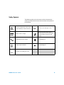
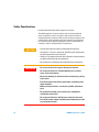
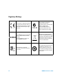
Agilent U8030A Series
Triple Output DC Power
Supply
User’s Guide
Agilent Technologies
Notices
© Agilent Technologies, Inc., 2011-2012
Warranty
No part of this manual may be reproduced in
any form or by any means (including electronic storage and retrieval or translation
into a foreign language) without prior agreement and written consent from Agilent
Technologies, Inc. as governed by United
States and international copyright laws.
The material contained in this document is
provided “as is,” and is subject to change,
without notice, in future editions. Further,
to the maximum extent permitted by the
applicable law, Agilent disclaims all warranties, either express or implied, with
regard to this manual and any information
contained herein, including but not limited
to the implied warranties of merchantability and fitness for a particular purpose.
Agilent shall not be liable for errors or for
incidental or consequential damages in
connection with the furnishing, use, or
performance of this document or of any
information contained herein. Should Agilent and the user have a separate written
agreement with warranty terms covering
the material in this document that conflict
with these terms, the warranty terms in
the separate agreement shall control.
Manual Part Number
U8031-90004
Edition
Third Edition, August 3, 2012
Agilent Technologies, Inc.
5301, Stevens Creek Blvd.
Santa Clara, CA 95051 USA
Technology Licenses
The hardware and or software described in
this document are furnished under a license
and may be used or copied only in accordance with the terms of such license.
Restricted Rights Legend
U.S. Government Restricted Rights. Software and technical data rights granted to
the federal government include only those
rights customarily provided to end user customers. Agilent provides this customary
commercial license in Software and technical data pursuant to FAR 12.211 (Technical
Data) and 12.212 (Computer Software) and,
for the Department of Defense, DFARS
252.227-7015 (Technical Data - Commercial
Items) and DFARS 227.7202-3 (Rights in
Commercial Computer Software or Computer Software Documentation).
II
Safety Notices
CAUTION
A CAUTION notice denotes a hazard. It calls attention to an operating procedure, practice, or the likes
of that, if not correctly performed
or adhered to, could result in damage to the product or loss of important data. Do not proceed beyond a
CAUTION notice until the indicated
conditions are fully understood and
met.
WA R N I N G
A WARNING notice denotes a
hazard. It calls attention to an
operating procedure, practice, or
the likes of that, if not correctly
performed or adhered to, could
result in personal injury or death.
Do not proceed beyond a WARNING notice until the indicated
conditions are fully understood
and met.
U8030A Series User’s Guide
Safety Symbols
The following symbols on the instrument and in the documentation
indicate precautions which must be taken to maintain safe operation of
the instrument.
Caution, risk of danger (refer to this manual
for specific Warning or Caution information)
In position of a bi-stable push control
DC (Direct current or voltage)
Terminal is at earth potential. Used for
measurement and control circuits designed to
be operated with one terminal at earth
potential.
AC (Alternating current or voltage)
Positive binding post
Protective conductor terminal
Negative binding post
Out position of a bi-stable push control
U8030A Series User’s Guide
III
Safety Considerations
Read the information below before using this instrument.
The following general safety precautions must be observed during all
phases of operation, service, and repair of this instrument. Failure to
comply with these precautions or with specific warnings elsewhere in this
manual violates safety standards for design, manufacture, and intended
use of the instrument. Agilent Technologies assumes no liability for the
customer’s failure to comply with these requirements.
CAUTION
• Use the device with the cables provided with the shipment.
• If the device is used in a manner not specified by the manufacturer,
the device protection may be impaired.
• Always use dry cloth to clean the device. Do not use ethyl alcohol or
any other volatile liquid to clean the device.
• Do not permit any blockage of the ventilation holes of the device.
WA R N I N G
• Do not use the device if it appears damaged or defective.
• Do not operate the device around flammable gases or fumes,
vapor, or wet environments.
• Observe all markings on the device before connecting any wiring
to the device.
• Turn off the output of the power supply before connecting to the
output terminals.
• When servicing the device, use only the specified replacement
parts.
• Do not install substitute parts or perform any unauthorized
modification to the device.
• Do not operate the device with the cover removed or loosened.
• Use only the power adapter provided by the manufacturer to avoid
any unexpected hazards.
IV
U8030A Series User’s Guide
Environmental Conditions
This instrument is designed for indoor use and in an area with low
condensation. The table below shows the general environmental
requirements for this instrument.
NOTE
Environmental condition
Requirements
Operating temperature
0 °C to 40 °C
Storage temperature
–40 °C to 70 °C
Humidity
15% RH (relative humidity) to 85% RH at 40 °C
(non-condensing)
Altitude
Up to 2000 meters
Installation category
Installation Category II
Pollution degree
Pollution Degree 2
The U8030A Series Triple Output DC Power Supply complies with the following
safety and EMC requirements:
•
•
•
•
•
•
•
U8030A Series User’s Guide
IEC61326-1:2005 / EN61326-1:2006
CISPR 11:2003/ EN55011:2007
Canada: ICES/NMB-001: Issue 4, June 2006
Australia / New Zealand: AS/NZS CISPR11:2004
IEC 61010-1:2001 / EN 61010-1:2001 (2nd Edition)
Canada: CAN/CSA-C22.2 No. 61010-1-04
USA: ANSI/UL 61010-1:2004
V
Regulatory Markings
VI
The CE mark is a registered trademark
of the European Community. This CE
mark shows that the product complies
with all the relevant European Legal
Directives.
The C-tick mark is a registered
trademark of the Spectrum
Management Agency of Australia. This
signifies compliance with
the Australia EMC Framework
regulations under the terms of the
Radio Communication Act of 1992.
ICES/NMB-001 indicates that this ISM
device complies with the Canadian
ICES-001.
Cet appareil ISM est confomre a la
norme NMB-001 du Canada.
This instrument complies with the
WEEE Directive (2002/96/EC) marking
requirement. This affixed product label
indicates that you must not discard
this electrical or electronic product in
domestic household waste.
The CSA mark is a registered
trademark of the Canadian Standards
Association.
This symbol indicates the time period
during which no hazardous or toxic
substance elements are expected to
leak or deteriorate during normal use.
Forty years is the expected useful life
of the product.
U8030A Series User’s Guide
Waste Electrical and Electronic Equipment (WEEE) Directive 2002/96/EC
This instrument complies with the WEEE Directive (2002/96/EC) marking
requirement. This affixed product label indicates that you must not discard
this electrical or electronic product in domestic household waste.
Product Category:
With reference to the equipment types in the WEEE directive Annex 1, this
instrument is classified as a “Monitoring and Control Instrument” product.
The affixed product label is as shown below.
Do not dispose in domestic household waste.
To return this unwanted instrument, contact your nearest Agilent Service
Center, or visit
www.agilent.com/environment/product
for more information.
U8030A Series User’s Guide
VII
Declaration of Conformity (DoC)
The Declaration of Conformity (DoC) for this instrument is available on the
Agilent website. You can search the DoC by its product model or
description at the web address below.
http://regulations.corporate.agilent.com/DoC/search.htm
NOTE
VIII
If you are unable to search for the respective DoC, please contact your
local Agilent representative.
U8030A Series User’s Guide
Table of Contents
1
Introduction
About This Manual 18
Documentation map 18
Safety notes 18
Preparing Your Power Supply 19
Checking the shipment 19
Connecting power to the instrument 20
Checking the instrument output 21
Rack-mounting the instrument 24
Enabling or disabling the backlight 25
Your Power Supply in Brief 26
Dimensions 26
Overview 27
Display screen 30
Output connections 33
Operating Your Power Supply
Cooling 34
Bench operation 34
Cleaning 34
List of Error Codes 35
System errors 35
Power channel errors
2
35
Operation and Features
Constant Voltage Operation
38
Constant Current Operation
40
5 V Operation 42
Overload condition
U8030A Series User’s Guide
34
42
IX
Circuit fault condition
Track Mode Operation
43
44
Output On/Off Operation 45
Turn on or off all outputs 45
Turn on or off individual outputs
46
Memory Operations 47
Storing an operating state 47
Recalling an operating state 48
Memory Output Operations 49
Enable the memory output single operation 49
Enable the memory output loop operation 50
Program the memory output time interval 51
Programming the Overvoltage Protection 52
Set the OVP trip level and enable the OVP 52
Disable the OVP 53
Clear the overvoltage condition 53
Programming the Overcurrent Protection 55
Set the OCP trip level and enable the OCP 55
Disable the OCP 56
Clear the overcurrent condition 56
Keylock Operation
58
System-Related Operations 59
Reset to the factory defaults 59
Power-on self-test 59
Display the firmware and board versions
Extending the Voltage and Current Range
Series connection 61
Parallel connection 62
X
60
61
U8030A Series User’s Guide
3
Characteristics and Specifications
Electrical Specifications
66
Physical Characteristics
67
Supplemental Characteristics
Protection Features
68
69
AC Power Input Specifications
Environmental Specifications
Connection Specifications
U8030A Series User’s Guide
69
70
70
XI
XII
U8030A Series User’s Guide
List of Figures
Figure 1-1
Figure 1-2
Figure 1-3
Figure 1-4
Figure 1-5
Figure 1-6
Figure 2-1
Figure 2-2
U8030A Series User’s Guide
Rack-mount adapter kit 24
U8030A Series rack-mount dimensions 24
U8030A Series dimensions 26
The front panel at a glance 27
The rear panel at a glance 29
The LCD display at a glance 30
Connecting units in series 62
Connecting units in parallel 63
XIII
XIV
U8030A Series User’s Guide
List of Tables
Table 1-1
Table 1-2
Table 1-3
Table 1-4
Table 1-5
Table 1-6
Table 3-1
Table 3-2
Table 3-3
Table 3-4
Table 3-5
Table 3-6
Table 3-7
U8030A Series User’s Guide
List of rated fuse for line voltages 21
Front panel legends and descriptions 27
Rear panel legends and descriptions 30
LCD display legends and descriptions 31
List of system error codes 35
List of power channel error codes 35
Electrical specifications 66
Physical characteristics 67
Supplemental characteristics 68
Protection features 69
AC power input specifications 69
Environmental specifications 70
Connection specifications 70
XV
XVI
U8030A Series User’s Guide
U8030A Series Triple Output DC Power Supply
User’s Guide
1
Introduction
About This Manual 18
Documentation map 18
Safety notes 18
Preparing Your Power Supply 19
Checking the shipment 19
Connecting power to the instrument 20
Checking the instrument output 21
Rack-mounting the instrument 24
Enabling or disabling the backlight 25
Your Power Supply in Brief 26
Dimensions 26
Overview 27
Display screen 30
Output connections 33
Operating Your Power Supply 34
Cooling 34
Bench operation 34
Cleaning 34
List of Error Codes 35
System errors 35
Power channel errors 35
This chapter teaches you how to set up your power supply
for the first time. An introduction to all the features of the
power supply is also given.
Agilent Technologies
17
1
Introduction
About This Manual
About This Manual
The descriptions and instructions in this manual apply to
the Agilent U8031A and U8032A triple output DC power
supplies (hereafter referred to as the power supply).
The model U8032A appears in all illustrations.
Documentation map
The following manuals are available for your power supply.
For the latest version, please visit our website at:
http://www.agilent.com/find/U8030.
Check the manual revision on the first page of each manual.
• User’s Guide. This manual.
• Quick Reference Guide. Printed copy, included with the
shipment.
• Service Guide. Free download at the Agilent website.
Safety notes
Safety notes are used throughout this manual (see the
“Safety Notices” section for format examples). Familiarize
yourself with each of the notes and its meaning before
operating your power supply.
More pertinent safety notes for using this product are
located under the “Safety Considerations” section.
Do not proceed beyond a safety notice until the indicated
conditions are fully understood and met.
18
U8030A Series User’s Guide
Introduction
Preparing Your Power Supply
1
Preparing Your Power Supply
Checking the shipment
When you receive your power supply, check the shipment
according to the following procedure.
1 Inspect the shipping container for damage. Signs of
damage may include a dented or torn shipping container
or cushioning material that indicates signs of unusual
stress or compacting. Save the packaging material in case
the power supply needs to be returned.
2 Carefully remove the contents from the shipping
container, and verify that the standard accessories and
your ordered options are included in the shipment
according to the standard shipped items list shown below.
3 For any question or problems, refer to the Agilent contact
numbers on the back of this manual.
Standard shipped items
Verify that you have received the following items in the
shipment of your power supply. If anything is found missing
or damaged, please contact your nearest Agilent Sales Office.
✔ One power cord
✔ One printed copy of the Certificate of Calibration
✔ One copy of the U8030A Series Product Reference
CD- ROM
Keep the original packaging in case the power supply has to
be returned to Agilent in the future. If you return the power
supply for service, attach a tag identifying the owner and
model number. Also, include a brief description of the
problem.
U8030A Series User’s Guide
19
1
Introduction
Preparing Your Power Supply
Connecting power to the instrument
Connect the power cord to the AC power connector (see
page 29 for the AC power connector location).
Before connecting the mains plug, ensure that the line
voltage selection is appropriate for your location (100 V,
115 V, or 230 V). The mains plug should only be inserted
into a socket outlet that provides protective earth contact.
Push the power switch to turn on the instrument.
The front- panel display illuminates while the power supply
performs its power- on self- test. (If the instrument does not
power- on, refer to the steps below). If self- test is successful,
the power supply goes into normal operation.
NOTE
The power supply is shipped from the factory with a power-line cord that
has a plug appropriate for your location. Your power supply is equipped
with a three-wire grounding type power cord; the third conductor being the
ground. The power supply is grounded only when the power-line cord is
plugged into an appropriate receptacle. Do not operate your power supply
without an adequate cabinet ground connection.
If the instrument does not turn on
Use the following steps to help solve problems you might
encounter when turning on the instrument. If you need more
help, refer to the U8030A Series Service Guide for
instructions on returning the instrument to Agilent
Technologies for service.
1 Verify that there is AC power to the power supply.
First, verify that the power cord is firmly plugged into the
power receptacle on the rear panel of the power supply.
You should also make sure that the power source you
plugged the power supply into is energized. Then, verify
that the power supply is turned on.
20
U8030A Series User’s Guide
Introduction
Preparing Your Power Supply
1
2 Verify the power- line voltage setting.
The line voltage is set to the proper value for your
country when the power supply is shipped from the
factory. Change the voltage setting if it is not correct. The
settings are: 100, 115, or 230 VAC.
3 Verify that the correct power- line fuse is installed.
The correct fuse for your country is installed when the
power supply is shipped from the factory. See the table
below to replace the fuse for your power supply.
Table 1-1 List of rated fuse for line voltages
Model
Agilent part number
Part description
U8031A/
U8032A
2110-1504
FUSE 1.0 A TIME-DELAY 0.0757 Ω
20 mm × 5.2 mm × 5.2 mm
Checking the instrument output
The following procedures check to ensure that the power
supply develops its rated outputs and properly responds to
operation from the front panel. For complete performance
and verification tests, refer to the U8030A Series Service
Guide.
From the front- panel VFD (vacuum- fluorescent display), you
can monitor actual values of output voltage and current
(meter mode) or voltage and current limit values (limit
mode).
NOTE
U8030A Series User’s Guide
If an error is detected during the output checkout procedure, the Err
annunciator will turn on. For more information, refer to the “List of Error
Codes” on page 35.
21
1
Introduction
Preparing Your Power Supply
Voltage output check
The following steps verify basic voltage functions with no
load.
1 Turn on the power supply.
The power supply starts up for the first time in the
power- on (reset) state — all the outputs are disabled (the
OFF annunciator is turned on).
2 Enable the outputs.
Press the [All On/Off] button once. Notice that the display
is in the meter mode.
3 Press [1] or [2] to switch between Output 1 and Output 2
(the OUT1 and OUT2 annunciators will turn on and off
respectively). Check that the front- panel voltmeter
properly responds to the knob control for both outputs.
Turn the knob clockwise or counterclockwise to check
that the voltmeter responds to the knob control and the
ammeter indicates nearly zero.
4 Ensure that the voltage can be adjusted from zero to the
full rated value by adjusting the knob.
5 Disable the outputs, and turn off the power supply.
NOTE
For subsequent power cycles, the power supply returns to the last
power-off state (when power is applied) by default.
Current output check
The following steps verify basic current functions with a
short across the power supply output.
1 Turn off the power supply.
2 Connect a short across the (+) and (–) output terminals of
Output 1 with an insulated test lead.
Use a wire size sufficient to handle the maximum current
(refer to the American Wire Gauge standard).
22
U8030A Series User’s Guide
Introduction
Preparing Your Power Supply
1
3 Turn on the power supply.
Ensure that all the outputs are disabled (the OFF
annunciator is turned on).
4 Enable the output for Output 1.
Press the [Output 1 On/Off] button (the OFF annunciator for
OUT1 turns off). Notice that the display is in the meter
mode.
5 Adjust the voltage limit value to 1.00 V.
Press the [Display Limit] button to set the display to the
limit mode (the LIMIT annunciator turns on).
Adjust the voltage limit to 1.00 V to ensure constant
current (CC) operation. The CC annunciator will turn on.
Press the [Display Limit] button again or allow the power
supply to idle for a few seconds to exit the limit mode.
6 Check that the front- panel ammeter properly responds to
the knob control for Output 1.
Press the [Voltage/Current] button. Ensure that the A
annunciator is blinking before proceeding with the next
step.
Turn the knob clockwise or counterclockwise when the
display is in the meter mode (the LIMIT annunciator is
off). Check that the ammeter responds to the knob control
and the voltmeter indicates nearly zero (the voltmeter will
show the voltage drop caused by the test lead).
7 Ensure that the current can be adjusted from zero to the
full rated value by adjusting the knob.
8 Repeat step 1 to step 7 for Output 2. Press [1] or [2] to
switch between Output 1 and Output 2 (the OUT1 and
OUT2 annunciators will turn on and off respectively).
9 Disable the outputs, turn off the power supply, and
remove the short from the output terminals.
U8030A Series User’s Guide
23
1
Introduction
Preparing Your Power Supply
Rack-mounting the instrument
You can mount the power supply in a standard 19- inch rack
cabinet. Instructions and mounting hardware are included
with the rack- mounting kit.
To rack- mount a single instrument, order adapter kit
5063- 9245.
Figure 1-1 Rack-mount adapter kit
Figure 1-2 U8030A Series rack-mount dimensions
24
U8030A Series User’s Guide
Introduction
Preparing Your Power Supply
1
Enabling or disabling the backlight
You can enable or disable the LCD backlight through the
front panel. Press the [Back Light] button to disable the LCD
backlight.
If viewing the display becomes difficult in low- light
conditions, press the [Back Light] button again to enable the
LCD backlight.
NOTE
U8030A Series User’s Guide
The LCD backlight is enabled by default upon power-on.
25
1
Introduction
Your Power Supply in Brief
Your Power Supply in Brief
Dimensions
179.0 mm
379.0 mm
212.3 mm
Figure 1-3 U8030A Series dimensions
26
U8030A Series User’s Guide
Introduction
Your Power Supply in Brief
1
Overview
Front panel
The front panel parts of your power supply are described in
this section.
Figure 1-4 The front panel at a glance
Table 1-2 Front panel legends and descriptions
U8030A Series User’s Guide
Legend
Description
1
LCD display
Displays the instrument settings and readings.
2
[Memory]
Stores the current operating state or recalls a
previously stored operating state from the
available memory locations (M1, M2, or M3).
27
1
Introduction
Your Power Supply in Brief
Table 1-2 Front panel legends and descriptions (continued)
28
Legend
Description
3
[Memory Output]
Recalls all stored operating in sequence once
(single) or in a loop.
4
[Δ t]
Adjusts the memory output time interval.
5
[Output 1 On/Off]
Enables or disables the power supply output from
the Output 1 binding posts.
6
[Over Voltage]
Enables or disables the overvoltage protection
function, sets the trip voltage level, and clears the
overvoltage condition.
7
[Over Current]
Enables or disables the overcurrent protection
function, sets the trip current level, and clears the
overcurrent condition.
8
[Back Light]
Turns the LCD backlight on or off.
9
[Output 2 On/Off]
Enables or disables the power supply output from
the Output 2 binding posts.
10
[Display Limit]
Displays and sets the voltage and current limit
values.
11
[Voltage/Current]
Selects the knob control function for voltage or
current adjustment.
12
[Lock/Unlock]
Enables or disables the front panel operation.
13
[5 V On/Off]
Enables or disables the power supply output from
the 5 V binding posts.
14
[All On/Off]
Enables or disables the power supply output from
all the binding posts (Output 1, Output 2, and 5 V).
15
Knob
Increases and decreases the value of the blinking
digit on the LCD display
16
[1]
Selects the knob control function for Output 1
adjustment.
17
[2]
Selects the knob control function for Output 2
adjustment.
18
[Track]
Sets the voltage and current settings of Output 1
or Output 2 to follow each other.
U8030A Series User’s Guide
Introduction
Your Power Supply in Brief
1
Table 1-2 Front panel legends and descriptions (continued)
Legend
Description
19
[POWER]
Turns the power supply on or off.
20
Output 1
binding posts
Positive, negative, and ground (shared) binding
posts for Output 1 wire connections.
21
Output 2
binding posts
Positive, negative, and ground (shared) binding
posts for Output 2 wire connections.
22
5 V binding posts
Positive and negative binding posts for 5 V output
wire connections.
Rear panel
The rear panel parts of your power supply are described in
this section.
1
4
2
3
5
Figure 1-5 The rear panel at a glance
U8030A Series User’s Guide
29
1
Introduction
Your Power Supply in Brief
Table 1-3 Rear panel legends and descriptions
Legend
Description
1
AC line fuse
To maintain protection, replace this fuse only with
a fuse of the specified type and rating.
2
AC inlet
Connects the AC power line. Plug the power cord
firmly in here.
3
Line voltage and
fuse rating selector
Set the line voltage and line fuse rating to the
proper values that are appropriate for your
location.
4
Ventilation fan
Ventilation fan to exhaust heat and air from the
instrument.
5
Physical lock
mechanism
Enables the physical lock mechanism.
Display screen
The display annunciators of your power supply are described
in this section.
1
2
3
4
5
6
7
19
8
9
20
21
10
11
12
13
14
15
22
16
17
18
Figure 1-6 The LCD display at a glance
30
U8030A Series User’s Guide
Introduction
Your Power Supply in Brief
1
Table 1-4 LCD display legends and descriptions
Legend
Description
1
M1
2
M2
Stores the current power supply operating state in
the power supply non-volatile memory.
3
M3
When the Δt annunciator is steady, the single
memory output operation is active.
4
Δt
5
LOCK
Front panel operation is disabled.
6
LIMIT
The voltage and current limit values are shown in
the display.
7
OFF
All the power supply outputs are disabled.
8
88.88 V
9
8.88 A
Line 1: Voltage and current values display for
Output 1.
10
88.88 V
11
8.88 A
12
13
U8030A Series User’s Guide
When the power supply is in the calibration mode,
these states can be used to store the calibration
constants.
OVP1
OCP1
When the Δt annunciator is blinking, the loop
memory output operation is active.
Line 2: Voltage and current values display for
Output 2.
When the OVP1 annunciator is steady, the
overvoltage protection function for Output 1 is
enabled.
When the OVP1 annunciator is blinking, an
overvoltage condition has occurred. The power
supply output is disabled until the trip is cleared.
When the OCP1 annunciator is steady, the
overcurrent protection function for Output 1 is
enabled.
When the OCP1 annunciator is blinking, an
overcurrent condition has occurred. The power
supply output is disabled until the trip is cleared.
31
1
Introduction
Your Power Supply in Brief
Table 1-4 LCD display legends and descriptions
Legend
14
OVP2
Description
When the OVP2 annunciator is steady, the
overvoltage protection function for Output 2 is
enabled.
When the OVP2 annunciator is blinking, an
overvoltage condition has occurred. The power
supply output is disabled until the trip is cleared.
When the OCP2 annunciator is steady, the
overcurrent protection function for Output 2 is
enabled.
15
OCP2
16
5VOL
An overload condition has occurred in the 5 V
output channel. The power supply output is
disabled until the trip is cleared.
17
TRACK
The track operation is active.
18
5V
The power supply is supplying a constant voltage
of 5 V from the 5 V binding posts.
19
OUT1
Output 1 is selected.
CV
The power supply is supplying constant voltage
from the Output 1 binding posts.
CC
The power supply is supplying constant current
from the Output 1 binding posts.
OUT2
Output 2 is selected.
CV
The power supply is supplying constant voltage
from the Output 2 binding posts.
CC
The power supply is supplying constant current
from the Output 2 binding posts.
When the OCP2 annunciator is blinking, an
overcurrent condition has occurred. The power
supply output is disabled until the trip is cleared.
20
21
22
32
U8030A Series User’s Guide
Introduction
Your Power Supply in Brief
1
Output connections
WA R N I N G
Before attempting to connect wires to the front output terminals,
make sure to disable the power supply output first to avoid damage
to the circuits being connected.
Voltage drops
The load wires must be large enough to avoid excessive
voltage drops due to the impedance of the wires. In general,
if the wires are heavy enough to carry the maximum short
circuit current without overheating, excessive voltage drops
will not be a problem. The voltage drops across the load
wires should be limited to less than 2 V. Refer to the
American Wire Gauge (AWG) standard to calculate the
voltage drop for some commonly used AWG wire copper.
U8030A Series User’s Guide
33
1
Introduction
Operating Your Power Supply
Operating Your Power Supply
Cooling
The power supply can operate at rated specifications within
the temperature range of 0 °C to 40 °C. Power supply
loading is derated from 40 °C to 55 °C. A fan cools the
power supply by drawing air through the sides and
exhausting it out the back. Using an Agilent rack- mount will
not impede the flow of air.
Bench operation
Your power supply must be installed in a location that
allows sufficient space at the sides and rear of the power
supply for adequate air circulation.
Cleaning
No cleaning is required for this product. If you wish to
remove dust from the enclosure, use a dry cloth.
34
U8030A Series User’s Guide
Introduction
List of Error Codes
1
List of Error Codes
The following errors indicate failures that may occur while
operating the power supply.
System errors
Table 1-5 List of system error codes
Error code
Description
001
Failed firmware test
002
Failed RAM test
003
Flash read/write error
Power channel errors
Table 1-6 List of power channel error codes
U8030A Series User’s Guide
Error code
Description
104
EEPROM write error
105
Analog board firmware update error
106
Analog board firmware checksum error
107
EEPROM read error
108
Failed to calibrate voltage DAC
109
Failed to calibrate voltage ADC
110
Failed to calibrate OVP
111
Failed to calibrate current DAC
112
Failed to calibrate current ADC
35
1
Introduction
List of Error Codes
Table 1-6 List of power channel error codes (continued)
36
Error code
Description
113
Failed to calibrate OCP
119
Analog board unknown error
120
Over temperature
130
Failed EEPROM test
131
Failed voltage +15 V
132
Failed voltage +5 V
133
Failed voltage +2.5 VREF
134
Failed voltage +1 VREF
135
Failed ADC test
136
Failed DAC test
140
Failed communication with analog board
141
Unsupported analog board
U8030A Series User’s Guide
U8030A Series Triple Output DC Power Supply
User’s Guide
2
Operation and Features
Constant Voltage Operation 38
Constant Current Operation 40
5 V Operation 42
Track Mode Operation 44
Output On/Off Operation 45
Memory Operations 47
Memory Output Operations 49
Programming the Overvoltage Protection 52
Programming the Overcurrent Protection 55
Keylock Operation 58
System-Related Operations 59
Extending the Voltage and Current Range 61
This chapter shows you the operations and features for the
U8030A Series triple output DC power supplies.
Agilent Technologies
37
2
Operation and Features
Constant Voltage Operation
Constant Voltage Operation
The following steps show you how to perform the constant
voltage (CV) operation.
1 Turn on the power supply.
• Press the [POWER] button to turn on the power supply.
• The power supply will then perform a self- test
(self- test is not indicated at the display).
• The display turns on all annunciators briefly.
• The outputs are disabled by default. The OFF
annunciator turns on.
• The display shows OFF for both outputs (line 1 and 2).
2 Select an output channel.
• Press [1] to select Output 1, or
• Press [2] to select Output 2.
• The corresponding annunciator (OUT1 or OUT2) turns
on.
3 Set the display to the limit mode.
• Press the [Display Limit] button to set the display to the
limit mode. The LIMIT annunciator turns on.
• The display will show the voltage and current limit
values for the selected output.
• The display for the non- selected output remains
unchanged.
NOTE
38
When you press the [Display Limit] button, the voltage and current limit
values will be shown on the display for about five seconds. If there is no
activity detected, the display will return to the meter mode.
U8030A Series User’s Guide
Operation and Features
Constant Voltage Operation
2
4 Adjust for the desired output voltage.
• Press the [Voltage/Current] button if necessary until the
V annunciator blinks.
• While the V annunciator is blinking, turn the knob to
adjust for the desired output voltage value.
5 Adjust for the desired current limit.
• Press the [Voltage/Current] button if necessary until the
A annunciator blinks.
• While the A annunciator is blinking, turn the knob to
adjust for the desired current limit value.
6 Return to the meter mode.
• Press the [Display Limit] button to return to the meter
mode.
• The LIMIT annunciator turns off.
7 Enable the output.
• Press the [Output 1 On/Off] or [Output 2 On/Off] button to
enable the output.
• The OFF annunciator turns off and the CV annunciator
turns on for the corresponding output.
• The display is now in the meter mode.
NOTE
U8030A Series User’s Guide
Verify that the power supply is in the constant voltage mode. Ensure that
the constant voltage (CV) annunciator is on. If the constant current (CC)
annunciator is on instead, choose a higher current limit.
39
2
Operation and Features
Constant Current Operation
Constant Current Operation
The following steps show you how to perform the constant
current (CC) operation.
1 Short the binding posts.
• Press the [POWER] button to turn off the power supply.
• Connect a short circuit between the positive (+) and
negative (—) binding posts of your desired output.
2 Turn on the power supply.
• Press the [POWER] button to turn on the power supply.
• The power supply will then perform a self- test
(self- test is not indicated at the display).
• The display turns on all annunciators briefly.
• The outputs are disabled by default (the OFF
annunciator turns on).
• The display shows OFF for both outputs (line 1 and 2).
3 Select an output channel.
• Press [1] to select Output 1, or
• Press [2] to select Output 2.
• The corresponding annunciator (OUT1 or OUT2) turns
on.
4 Set the display to the limit mode.
• Press the [Display Limit] button to set the display to the
limit mode. The LIMIT annunciator turns on.
• The display will show the voltage and current limit
values for the selected output.
• The display for the non- selected output remains
unchanged.
40
U8030A Series User’s Guide
Operation and Features
Constant Current Operation
NOTE
2
When you press the [Display Limit] button, the voltage and current limit
values will be shown on the display for about five seconds. If there is no
activity detected, the display will return to the meter mode.
5 Adjust for the desired voltage limit.
• Press the [Voltage/Current] button if necessary until the
V annunciator blinks.
• While the V annunciator is blinking, turn the knob to
adjust for the desired output voltage value.
6 Adjust for the desired output current.
• Press the [Voltage/Current] button if necessary until the
A annunciator blinks.
• While the A annunciator is blinking, turn the knob to
adjust for the desired current limit value.
7 Return to the meter mode.
• Press the [Display Limit] button to return to the meter
mode.
• The LIMIT annunciator turns off.
8 Enable the output.
• Press the [Output 1 On/Off] or [Output 2 On/Off] button to
enable the output.
• The OFF annunciator turns off and the CC annunciator
turns on for the corresponding output.
• The display is now in the meter mode.
NOTE
U8030A Series User’s Guide
Verify that the power supply is in the constant current mode. Ensure that
the constant current (CC) annunciator is on. If the constant voltage (CV)
annunciator is on instead, choose a higher voltage limit.
41
2
Operation and Features
5 V Operation
5 V Operation
The following steps show you how to output a constant 5 V
from the 5 V output channel.
1 Turn on the power supply.
• Press the [POWER] button to turn on the power supply.
• The power supply will then perform a self- test
(self- test is not indicated at the display).
• The display turns on all annunciators briefly.
• The outputs are disabled by default. The OFF
annunciator turns on.
• The display shows OFF for both outputs (line 1 and 2).
2 Enable the 5 V output.
• Press the [5 V On/Off] button to enable the 5 V output.
• The OFF annunciator turns off and the 5 V annunciator
turns on.
3 Disable the 5 V output.
• Press the [5 V On/Off] button again to disable the 5 V
output.
• The 5 V annunciator turns off.
Overload condition
When an overload condition is detected, the 5 V output will
be disabled automatically.
• The 5 V annunciator turns off.
• The 5VOL annunciator turns on.
• To clear the overload condition and enable the 5V output
in a single step, press the [5 V On/Off] button.
42
U8030A Series User’s Guide
Operation and Features
5 V Operation
2
Circuit fault condition
When an internal circuit fault is detected, the 5 V output
will be disabled automatically.
• The 5 V annunciator blinks.
• The circuit fault condition might be cleared by cycling the
unit power.
• If the fault condition persists, stop using the unit and
send it to an authorized service center for repair.
U8030A Series User’s Guide
43
2
Operation and Features
Track Mode Operation
Track Mode Operation
When the track mode is enabled, the voltage settings of
Output 1 and Output 2 will mirror each other. The following
steps show you how to track the voltage of the selected
output.
1 Select an output channel.
• Press [1] to select Output 1, or
• Press [2] to select Output 2.
• The corresponding annunciator (OUT1 or OUT2) turns
on.
2 Set the desired voltage setting for the selected output
channel.
• Repeat step 3 to step 7 from the “Constant Voltage
Operation” on page 38.
3 Enable the track mode.
• Press and hold the [Track] button. The display shows
HOLd until the track mode is enabled.
• The TRACK annunciator turns on.
• The voltage setting of the non- selected output is set to
the same voltage setting of the selected output.
4 Disable the track mode.
• Press the [Track] button again. The TRACK annunciator
turns off.
• The track mode is disabled.
44
U8030A Series User’s Guide
Operation and Features
Output On/Off Operation
2
Output On/Off Operation
The following steps show you how to turn on all outputs at
the same time or to turn on each output individually.
Turn on or off all outputs
When the power supply is turned on, all outputs (Output 1,
Output 2, and the 5 V output) are disabled by default.
1 Enable all outputs at the same time.
• Press the [All On/Off] button to enable all the outputs in
a single button press.
• The OFF annunciator turns off.
• The display shows voltage and current values for
Output 1 on line 1 and Output 2 on line 2.
• The 5 V annunciator turns on.
2 Disable all outputs at the same time.
• If any of the outputs are enabled, pressing the [All
On/Off] button will disable all the outputs.
NOTE
If all the outputs are disabled, pressing the [All On/Off] button will enable
all the outputs.
U8030A Series User’s Guide
45
2
Operation and Features
Output On/Off Operation
Turn on or off individual outputs
Each output can be individually enabled or disabled by
pressing its corresponding On/Off button.
1 Enable or disable Output 1.
• Press the [Output 1 On/Off] button to enable Output 1.
• The display shows voltage and current values for
Output 1 on line 1.
• The display Output 2 on line 2 remains unchanged.
• Press the [Output 1 On/Off] button again to disable
Output 1.
2 Enable or disable Output 2.
• Press the [Output 2 On/Off] button to enable Output 2.
• The display shows voltage and current values for
Output 2 on line 2.
• The display Output 1 on line 1 remains unchanged.
• Press the [Output 2 On/Off] button again to disable
Output 2.
3 Enable or disable the 5 V output.
• Press the [5 V On/Off] button to enable the 5 V output.
• The 5 V annunciator turns on.
• The display Output 1 and Output 2 on line 1 and 2
remains unchanged.
• Press the [5 V On/Off] button again to disable the 5 V
output.
NOTE
46
The OFF annunciator turns on only when all the three outputs are disabled.
U8030A Series User’s Guide
Operation and Features
Memory Operations
2
Memory Operations
Up to three operating states can be stored in the
non- volatile storage locations. The storage feature remembers
the voltage and current limit value settings; OVP and OCP
on or off states; and OVP and OCP trip levels. The following
steps show you how to store and recall an operating state.
Storing an operating state
1 Store the power supply current operating state.
• Press the [Memory] button.
• The M1 annunciator will blink.
2 Turn the knob to choose the memory location for
storing the operation state.
• The M1, M2, and M3 annunciators will blink in a
round- robin manner.
3 Press the [Memory] button again to save the current
operating state in the chosen memory location.
• The display will show dOnE.
• The M1, M2, and M3 annunciators turn off.
NOTE
U8030A Series User’s Guide
To cancel this operation, allow the unit to idle for five seconds.
47
2
Operation and Features
Memory Operations
Recalling an operating state
1 Recall a previously stored operating state.
• Press and hold the [Memory] button until the M1
annunciator stops blinking.
• The M1 annunciator turns on.
• The display shows the settings stored in the M1
memory location.
2 Turn the knob to show the settings saved in M1, M2,
and M3 memory locations.
• The M1, M2, and M3 annunciators will turn on in a
round- robin manner.
• The display shows the settings stored in the M1 , M2,
and M3 memory location in a round- robin manner.
3 Press the [Memory] button again to recall the stored
operating state in the chosen memory location.
• The display will show dOnE.
• The M1, M2, and M3 annunciators turn off.
NOTE
48
To cancel this operation, allow the unit to idle for five seconds.
U8030A Series User’s Guide
Operation and Features
Memory Output Operations
2
Memory Output Operations
The Memory Output feature allows operating states from the
M1, M2, and M3 memory locations to be recalled
automatically in sequential order.
Three time intervals are programmable:
• Δt1 — time delay between recalling M1 and recalling M2.
• Δt2 — time delay between recalling M2 and recalling M3.
• Δt3 — time delay between recalling M3 and recalling M1.
Enable the memory output single operation
1 Enable the memory output single operation.
• Press and hold the [Memory Output] button. The display
shows HOLd until the memory output operation is
enabled.
• The Δt annunciator turns on, and all the M1, M2, and
M3 annunciators turn on.
• The operating state from M1 memory location is
recalled immediately.
• The M1 annunciator blinks. The M2 and M3
annunciators are steadily on.
• After waiting for Δt1, the operating state from M2
memory location is recalled.
• The M2 annunciator blinks. The M1 and M3
annunciators are steadily on.
• After waiting for Δt2, the operating state from M3
memory location is recalled.
• The M3 annunciator blinks for two seconds. The M1
and M2 annunciators are steadily on.
• The memory output operation is completed.
U8030A Series User’s Guide
49
2
Operation and Features
Memory Output Operations
• The Δt annunciator turns off, and all the M1, M2, and
M3 annunciators turn off.
Enable the memory output loop operation
1 Enable the memory output loop operation.
• Press and hold the [Memory Output] button until the Δt
annunciator starts to blink. (The Δt annunciator turns
on first before it starts to blink.)
• All the M1, M2, and M3 annunciators turn on.
• The operating state from M1 memory location is
recalled immediately.
• The M1 annunciator blinks. The M2 and M3
annunciators are steadily on.
• After waiting for Δt1, the operating state from M2
memory location is recalled.
• The M2 annunciator blinks. The M1 and M3
annunciators are steadily on.
• After waiting for Δt2, the operating state from M3
memory location is recalled.
• The M3 annunciator blinks. The M1 and M2
annunciators are steadily on.
• After waiting for Δt3, the operating state from M1
memory location is recalled.
• The process is repeated infinitely until canceled.
2 Cancel the memory output loop operation.
• Pressing the [Memory Output] button during the memory
output loop operation will terminate the operation
immediately.
• All outputs will be disabled.
• The OFF annunciator turns on.
50
U8030A Series User’s Guide
Operation and Features
Memory Output Operations
2
Program the memory output time interval
1 Edit the memory output time interval.
• Press the [Δt] button.
• The Δt annunciator turns on.
• By default, the M1 annunciator turns on indicating Δt1
is being selected for adjustment.
• To select Δt2 or Δt3, press the [Memory] button until the
corresponding M2 or M3 annunciator turns on.
• The display shows the time interval in seconds, with
the integral part on line 1 and the fractional part on
line 2.
• Press the [Δt] button to change the cursor position.
Turn the knob to adjust the value. The time interval
can be set with a resolution up to 10 ms.
• You can set the time interval within the range of 0 s to
9999.99 s.
• Press and hold the [Δt] button to save the setting.
• The display shows dOnE.
NOTE
U8030A Series User’s Guide
To cancel this operation, allow the unit to idle for five seconds.
51
2
Operation and Features
Programming the Overvoltage Protection
Programming the Overvoltage Protection
Overvoltage protection guards the load against output
voltages reaching values greater than the programmed
protection level.
The following steps shows you how to enable and disable the
overvoltage protection (OVP), how to set the OVP trip level,
and how to clear the overvoltage condition.
Set the OVP trip level and enable the OVP
1 Select an output channel.
• Press [1] to select Output 1, or
• Press [2] to select Output 2.
• The corresponding annunciator (OUT1 or OUT2) turns
on.
2 Set the OVP trip level.
• Press the [Over Voltage] button.
• The LIMIT annunciator turns off.
• The corresponding OVP annunciator (OVP1 or OVP2) will
blink continuously.
• The display will show the OVP value for the selected
output.
• The V annunciator will blink continuously.
3 Turn the knob to adjust the OVP value.
• While the V annunciator is blinking, turn the knob and
adjust to the desired OVP value.
52
U8030A Series User’s Guide
Operation and Features
Programming the Overvoltage Protection
2
4 Enable the OVP.
• Press the [Over Voltage] button again to end the
adjustment and enable the OVP.
• The display will show dOnE.
• The corresponding OVP annunciator (OVP1 or OVP2)
turns on.
NOTE
To cancel this operation, allow the unit to idle for five seconds.
Disable the OVP
1 Select an output channel with OVP enabled.
• Press [1] to select Output 1, or
• Press [2] to select Output 2.
• The corresponding annunciator (OUT1 or OUT2) turns
on.
2 Disable the OVP.
• Press the [Over Voltage] button again to disable the OVP.
• The corresponding OVP annunciator (OVP1 or OVP2)
turns off.
Clear the overvoltage condition
The OVP trip can only occur if the corresponding output is
enabled. When the OVP trip occurs, the corresponding
output is disabled automatically.
• If the OVP trip occurs on Output 1, the display shows triP
on line 1 and the OVP1 annunciator blinks.
U8030A Series User’s Guide
53
2
Operation and Features
Programming the Overvoltage Protection
• If the OVP trip occurs on Output 2, the display shows triP
on line 2 and the OVP2 annunciator blinks.
1 Select the output channel with the OVP trip.
• Press [1] to select Output 1, or
• Press [2] to select Output 2.
• The corresponding annunciator (OUT1 or OUT2) turns
on.
2 Clear the OVP trip.
• Press the [Over Voltage] button again to clear the OVP
trip.
NOTE
54
If the OVP trip persists, decrease the voltage limit settings to clear the
tripping.
U8030A Series User’s Guide
Operation and Features
Programming the Overcurrent Protection
2
Programming the Overcurrent Protection
Overcurrent protection guards the load against output
currents reaching values greater than the programmed
protection level.
The following steps shows you how to enable and disable the
overcurrent protection (OCP), how to set the OCP trip level,
and how to clear the overcurrent condition.
Set the OCP trip level and enable the OCP
1 Select an output channel.
• Press [1] to select Output 1, or
• Press [2] to select Output 2.
• The corresponding annunciator (OUT1 or OUT2) turns
on.
2 Set the OCP trip level.
• Press the [Over Current] button.
• The LIMIT annunciator turns off.
• The corresponding OCP annunciator (OCP1 or OCP2) will
blink continuously.
• The display will show the OCP value for the selected
output.
• The A annunciator will blink continuously.
3 Turn the knob to adjust the OCP value.
• While the A annunciator is blinking, turn the knob and
adjust to the desired OCP value.
U8030A Series User’s Guide
55
2
Operation and Features
Programming the Overcurrent Protection
4 Enable the OCP.
• Press the [Over Current] button again to end the
adjustment and enable the OCP.
• The display will show dOnE.
• The corresponding OCP annunciator (OCP1 or OCP2)
turns on.
NOTE
To cancel this operation, allow the unit to idle for five seconds.
Disable the OCP
1 Select an output channel with OCP enabled.
• Press [1] to select Output 1, or
• Press [2] to select Output 2.
• The corresponding annunciator (OUT1 or OUT2) turns
on.
2 Disable the OCP.
• Press the [Over Current] button again to disable the OCP.
• The corresponding OCP annunciator (OCP1 or OCP2)
turns off.
Clear the overcurrent condition
The OCP trip can only occur if the corresponding output is
enabled. When the OCP trip occurs, the corresponding
output is disabled automatically.
• If the OCP trip occurs on Output 1, the display shows triP
on line 1 and the OCP1 annunciator blinks.
56
U8030A Series User’s Guide
Operation and Features
Programming the Overcurrent Protection
2
• If the OCP trip occurs on Output 2, the display shows triP
on line 2 and the OCP2 annunciator blinks.
1 Select the output channel with the OCP trip.
• Press [1] to select Output 1, or
• Press [2] to select Output 2.
• The corresponding annunciator (OUT1 or OUT2) turns
on.
2 Clear the OCP trip.
• Press the [Over Current] button again to clear the OCP
trip.
NOTE
U8030A Series User’s Guide
If the OCP trip persists, decrease the current limit settings to clear the
tripping.
57
2
Operation and Features
Keylock Operation
Keylock Operation
This operation provides a locking function for the knob and
all the buttons on the front panel of the power supply,
which allows you to secure your desired settings.
The keylock is disabled by default upon power- up.
1 Enable the keylock.
• Press the [Lock/Unlock] button.
• The LOCK annunciator turns on.
• When the keylock function is enabled, the knob and all
the buttons are disabled except the [Lock/Unlock]
button.
2 Disable the keylock.
• Press and hold the [Lock/Unlock] button for more than
one second.
• While the [Lock/Unlock] button is being held down, the
display will show HOLd until the keylock is disabled.
• After the keylock is disabled, the LOCK annunciator
turns off.
58
U8030A Series User’s Guide
Operation and Features
System-Related Operations
2
System-Related Operations
Reset to the factory defaults
To reset to factory defaults, press and hold the [All On/Off]
button when powering on the unit until the display shows
dOnE.
• The OVP and OCP are disabled, and their trip levels are
set to maximum (i.e., 10% above the CV and CC rated
values).
• All memory storage locations are cleared.
• The voltage limit value is set to 0, while the current limit
value is set to the maximum rated value.
• The calibration data are not affected by the factory
default reset.
Power-on self-test
A power- on self- test occurs automatically when the power
supply unit is turned on. This test ensures the unit is
operational. The power- on self- test checks for flash data
memory and checks the voltage and current outputs when
the unit is turned off.
NOTE
U8030A Series User’s Guide
If the test fails, the display will show Err along with the error code. For
more information, refer to the “List of Error Codes” on page 35.
59
2
Operation and Features
System-Related Operations
Display the firmware and board versions
To display the firmware and board versions, press and hold
the [Over Voltage] and [Display Limit] buttons simultaneously
when powering on the unit.
• The display shows the front panel firmware version on
line 1 for one second.
• After that, the display shows:
• the firmware and board versions of analog board 1 on
line 1, and
• the firmware and board versions of analog board 2 on
line 2 for one second.
60
U8030A Series User’s Guide
Operation and Features
Extending the Voltage and Current Range
2
Extending the Voltage and Current Range
CAUTION
• Never exceed the floating voltage rating of any of the supplies.
• Never subject any of the power supplies to negative voltages.
Two or more power supplies can be connected in series or
parallel to extend the range of voltage and current. This may
serve as a lower cost alternative to a power supply with
higher power rating.
Series connection
Serial connection of two or more power supplies can achieve
the output isolation rating of any one supply to obtain a
higher voltage than a single power supply. Power supplies
connected in series can be operated with one load across
both power supplies or with a separate load for each power
supply. The power supply has a diode with reverse polarity
connected across the output terminals to avoid any damages
when operated in series with other power supplies. It will be
protected if the load is short- circuited, or when one of the
power supply is turned on separately in a series- connected
power supplies.
When serial connection is used, the output voltage is the
sum of output voltage across all power supplies, while the
output current is the output current from an individual
power supply. Each power supply must be adjusted to obtain
the total output voltage.
U8030A Series User’s Guide
61
2
Operation and Features
Extending the Voltage and Current Range
Figure 2-1 Connecting units in series
Parallel connection
Two or more power supplies which are capable of constant
voltage or constant current automatic cross- over operation
can be connected in parallel to obtain a total output current
greater than one power supply. Total output current is the
sum of output current across all power supplies. The output
settings from each power supply can be made separately.
The control of output voltage for one of the power supply
should be set to the desired output value, while the other
power supply should be set to a slightly higher output
voltage. The power supply with higher output voltage setting
will deliver its constant current output and drop its output
voltage. This will happen until the output voltage equals the
output of the other supply, and the other supply will remain
in constant voltage operation; only delivering that fraction of
rated output current that is necessary to fulfill the total load
demand.
62
U8030A Series User’s Guide
Operation and Features
Extending the Voltage and Current Range
2
Figure 2-2 Connecting units in parallel
U8030A Series User’s Guide
63
2
Operation and Features
Extending the Voltage and Current Range
THIS PAGE HAS BEEN INTENTIONALLY LEFT BLANK.
64
U8030A Series User’s Guide
U8030A Series Triple Output DC Power Supply
User’s Guide
3
Characteristics and Specifications
Electrical Specifications 66
Physical Characteristics 67
Supplemental Characteristics 68
Protection Features 69
AC Power Input Specifications 69
Environmental Specifications 70
Connection Specifications 70
This chapter lists the characteristics and specifications of
the U8031A and U8032A triple output DC power supplies.
Agilent Technologies
65
3
Characteristics and Specifications
Electrical Specifications
Electrical Specifications
NOTE
The specifications stated are based on a 1 hour warm-up period.
Table 3-1 Electrical specifications
Parameter
U8031A
Total power output (W)
0 W to 375 W
U8032A
Voltage output (V)
Output Channel 1 & 2
(@ 0 °C to 40 °C)
0 V to 30 V
0 V to 60 V
0 A to 6 A
0 A to 3 A
Current output (A)
Output Channel 1 & 2
(@ 0 °C to 40 °C)
Three isolated output
Number of outputs
5 V fixed output[1]
Output Channel 3
• Two variable: CV and CC operation
• One fixed: CV operation only
•
•
•
•
•
Voltage/Current output: 5 V, 3A
Output accuracy: ≤5% or (5 V ± 0.25 V)
Vrms: <2 mVrms, or Vpp: <50 mVpp
Load and line regulation: ≤5 mV
Overload condition: 3 A + 20% (typical)
Note:
[1] The specifications referenced in this row are for Output Channel 3 (5 V fixed output). All other specifications listed in this
table are intended for Output Channel 1 and 2, unless otherwise stated.
Line and load regulation (for variable output)
Ripple and noise
Based on calculation at temperature of 18 °C to 28 °C
and bandwidth at 20 Hz to 20 MHz.
Load transient response time
Within 15 mV from full load to half load and from half
load to full load.
66
• CV: <0.01% + 2 mV
• CC: <0.02% + 2 mA
• CV: ≤1 mVrms, 0.5 mVrms (typical) or ≤10 mVpp, 5 mVpp (typical)
• CC: ≤1 mArms
<50 μs
U8030A Series User’s Guide
Characteristics and Specifications
Physical Characteristics
3
Table 3-1 Electrical specifications (continued)
Parameter
U8031A
U8032A
Stability (output drift)
Following a 30-minute warm-up, with the output in the
ON state according to the operating mode (CC with load
or CV), and with a change in the output over 8 hours
under constant load, line, and ambient temperature.
• Voltage: <0.02%
• Current: <0.1%
Programming accuracy (23 °C ± 5 °C)
• CV: ≤0.25% + 15 mV
• CC: ≤0.30% + 15 mA
Meter readback accuracy (23 °C ± 5 °C)
• CV: ≤0.25% + 10 mV
• CC: ≤0.25% + 10 mA
Programming/Meter resolution
• Voltage: 10 mV (4 digits)
• Current: 10 mA (3 digits)
Maximum output float voltage
±240 VDC
Physical Characteristics
Table 3-2 Physical characteristics
Parameter
U8031A/U8032A
Display
LCD with amber backlight
Rotary knob for reading adjustment
Yes
Size
4U, half rack
Dimensions
179.0 mm × 212.3 mm × 379.0 mm
Weight
8.2 kg
U8030A Series User’s Guide
67
3
Characteristics and Specifications
Supplemental Characteristics
Supplemental Characteristics
Table 3-3 Supplemental characteristics
Parameter
U8031A/U8032A
Temperature coefficient (for 12 months)
±(% of output + offset)
• Output
• CV: (0.01% + 1 mV) / °C
• CC: (0.01% + 1 mA) / °C
• OVP, OCP
• CV: <0.05% / °C
• CC: <0.05% / °C
Output voltage overshoot
During turn-on or turn-off of AC power, if output control
is set less than 1 V.
<1 V
Voltage programming speed,
to within 1% of total excursion
30 V
60 V
Full load
80 ms
200 ms
No load
80 ms
100 ms
Full load
30 ms
30 ms
No load
150 ms
300 ms
Up
Down
Over-temperature protection
Yes
Last memory setting enabled
Yes
Three memory storage locations for voltage
and current settings
Yes
Erasing non-volatile memory
Yes, erasable through the front panel
Rack mount capability
Yes, front panel and rear have rack-mountable support
68
U8030A Series User’s Guide
Characteristics and Specifications
Protection Features
3
Protection Features
Table 3-4 Protection features
Parameter
U8031A
Overvoltage protection accuracy ± (% of
output + offset)
<0.5% +0.5V
Overvoltage protection programmable range
0.1 V to 33.0 V
Overvoltage protection response time
<10 ms
Overcurrent protection accuracy
<0.5% + 0.5 A
U8032A
0.1 V to 66.0 V
± (% of output + offset)
Overcurrent protection programmable range
0.1 A to 6.6 A
Overcurrent protection response time
<10 ms
0.1 A to 3.3 A
AC Power Input Specifications
Table 3-5 AC power input specifications
Parameter
U8031A/U8032A
Input power option (selectable)
• 100 Vac ± 10%, 47 Hz to 63 Hz
• 115 Vac ± 10%, 47 Hz to 63 Hz
• 230 Vac ± 10%, 47 Hz to 63 Hz
Maximum input power
600 VA
Fuse
External, located at the rear panel
U8030A Series User’s Guide
69
3
Characteristics and Specifications
Environmental Specifications
Environmental Specifications
Table 3-6 Environmental specifications
Parameter
U8031A/U8032A
Operating temperature
0 °C to 40 °C
Storage temperature
–40 °C to 70 °C
Humidity
15% RH (relative humidity) to 85% RH at 40 °C (non-condensing)
Altitude
Up to 2000 meters
Fan acoustic noise
• No load: follow Agilent Class CO, 45 dB sound pressure and 50 dB sound
power
• Full load: follow Agilent Class GP, 55 dB sound pressure and 60 dB sound
power
Environment of use
• Installation Category II
• Pollution Degree 2
Connection Specifications
Table 3-7 Connection specifications
Parameter
U8031A/U8032A
Output connections
+Out, –Out, and chassis ground on the front panel.
(Either positive or negative output terminal may be grounded or can be operated floating at up to
a maximum of 240 V off ground. Total output voltage to ground must not exceed 240 VDC)
Binding posts
Output binding post located horizontally and side by side
I/O connections
N/A
AC input
Three pins standard IEC AC power connector with fuse and line selection at
the rear
70
U8030A Series User’s Guide
www.agilent.com
Contact us
To obtain service, warranty, or technical
assistance, contact us at the following
phone or fax numbers:
United States:
(tel) 800 829 4444
(fax) 800 829 4433
Canada:
(tel) 877 894 4414
(fax) 800 746 4866
China:
(tel) 800 810 0189
(fax) 800 820 2816
Europe:
(tel) 31 20 547 2111
Japan:
(tel) (81) 426 56 7832 (fax) (81) 426 56 7840
Korea:
(tel) (080) 769 0800 (fax) (080) 769 0900
Latin America:
(tel) (305) 269 7500
Taiwan:
(tel) 0800 047 866
(fax) 0800 286 331
Other Asia Pacific Countries:
(tel) (65) 6375 8100 (fax) (65) 6755 0042
Or visit Agilent World Wide Web at:
www.agilent.com/find/assist
Product specifications and descriptions in
this document are subject to change
without notice. Always refer to the Agilent
website for the latest revision.
© Agilent Technologies, Inc., 2011-2012
Third Edition, August 3, 2012
U8031-90004
Agilent Technologies