1
SERIES
6075
TEMPERATURE CONTROLLERS
WITH AUTO-TUNING PID AND
PLUG-IN COMPUTER INTERFACE
Warranty Limitations
Other than those expressly stated herein,THERE ARE NO OTHER
WARRANTIES OF ANY KIND, EXPRESS OR lMPLlED, AND SPECIFICALLY EXCLUDED BUT NOT BY WAY OF LlMlTATlON, ARE THE
IMPLIED WARRANTIES OF FITNESS FOR A PARTICULAR PURPOSE
AND MERCHANTABILITY.
IT IS UNDERSTOOD AND AGREED THE SELLER’S LIABILITY
WHETHER IN CONTRACT, IN TORT, UNDER ANY WARRANTY, IN
NEGLIGENCE OR OTHERWISE SHALL NOT EXCEED THE RETURN
OF THE AMOUNT OF THE PURCHASE PRICE PAID BY THE PURCHASER AND UNDER NO CIRCUMSTANCES SHALL BE LIABLE
FOR SPECIAL, INDIRECT, INCIDENTAL, OR CONSEQUENTIAL
DAMAGES.THE PRICE STATED FOR THE EQUIPMENT IS A
CONSIDERATION IN LIMITING SELLER’S LIABILITY NO ACTION,
REGARDLESS OF FORM, ARISING OUT OF THE TRANSACTIONS
OF THIS AGREEMENT MAY BE BROUGHT BY PURCHASER MORE
THAN ONE YEAR AFTER THE CAUSE OF ACTION HAS ACCRUED.
SELLER’S MAXIMUM LIABILITY SHALL NOT EXCEED AND BUYER’S
REMEDY IS LIMITEDTO EITHER (i) REPAIR OR REPLACEMENT OF
THE DEFECTIVE PART OR PRODUCT, OR AT SELLER’S OPTION (ii)
RETURN OF THE PRODUCT AND REFUND OF THE PURCHASE
PRlCE, AND SUCH REMEDY SHALL BE BUYER’S ENTIRE AND
EXCLUSIVE REMEDY.
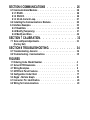
SERIES 6075
AUTO-TUNING PID TEMPERATURE CONTROLLER
PAGE
CONTENTS
SECTION 1 GENERAL INTRODUCTION . . . . . . . . . 1
1.1 General Description and Cautions . . . . . . . . . . . . . . . . . . . . . . 1
1.2 Specifications . . . . . . . . . . . . . . . . . . . . . . . . . . . . . . . . . . 2
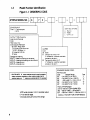
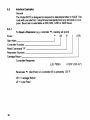
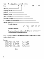
1.3 Model Number Identification . . . . . . . . . . . . . . . . . . . . . . . . . 4
SECTION 2 INSTALLATION INSTRUCTIONS
2.1 Unpacking. . . .
2.2 Locating. . . . .
2.3 Mounting. . . .
2.4 Removing Unit. .
2.5 Case Dimensions.
. . .
. . .
. . .
. . .
. . .
.
.
.
.
.
.
.
.
.
.
.
.
.
.
.
.
.
.
.
.
.
.
.
.
.
.
.
.
.
.
.
.
.
.
.
.
.
.
.
.
.
.
.
.
.
.
.
.
.
.
.
.
.
.
.
.
.
.
.
.
. . . . . . . . .
. . . . . . . . .
. . . . . . . .
. . . . . . . . .
. . . . . . . . .
5
5
5
5
5
6
SECTION 3 OUTPUT MODULES. . . . . . . . . . . . . . . . 7
3.1 Module Description. . . . . . . . . . . . . . . . . . . . . . . . . . . . . . . . . . . 7
SECTION 4 BASIC WIRING. . . . . . . . . . . . . . . . 8
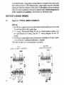
4.1 Typical Wiring Examples. . . . . . . . . . . . . . . . . . . . 8
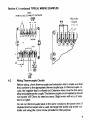
4.2 Wiring Thermocouple and RTD Circuits. . . . . . . . . . . . . . 9
SECTION 5 OPERATION. . . . . . . . . . . . . . . . . . . 12
5.1 Front Panel Features. . . . . . . . . . . . . . . . . . . . . .
5.2 Setup. . . . . . . . . . . . . . . . . . . . . . . . .
5.3 Tuning The Controller. . . . . . . . . . . . . . . . . .
5.3.1 Introduction. . . . . . . . . . . . . . . . . . . . . .
5.3.2 Automatic PlD Tuning Procedure. . . . . . . . . . . . .
5.3.2.1 Damping Settings. . . . . . . . . . . . . . . . .
5.3.2.2 Operating Instructions. . . . . . . . . . . . . . . . . .
5.3.3 Manual Tuning procedure. . . . . . . . . . . . . . . . . . .
.
.
.
.
.
.
.
.
. 13
. 14
. 20
. 20
. . 20
. . 20
. . . 21
. . . 22
SECTION 6 COMMUNICATIONS . . . . . . . . . . . 26
6.1 Communications Modules . . . . . . . . . . . . . . . . . . . . . . . 26
6.1.1 RS485. . . . . . . . . . . . . . . . . . . . . . . . . 26
6.1.2 RS232C. . . . . . . . . . . . . . . . . . . . . . . . . 26
6.1.3 20 mA Current Loop. . . . . . . . . . . . . . . . . . . 27
6.2 Installing the Communications Modules. . . . . . . . . . . . .
28
6.3 Interface Examples. . . . . . . . . . . . . . . . . . . . . . 30
6.3.1 Read Data. . . . . . . . . . . . . . . . . . . . . . . . . . . . . . . . . . 30
6.3.2 Modify (Temporary). . . . . . . . . . . . . . . . . . . . . . . . . 31
6.3.3 Modify and Store. . . . . . . . . . . . . . . . . . . . . . . . . . . . 32
SECTION 7 CALIBRATION. . . . . . . . . . . . 33
7.1 Zero and Span Adjustments. . . . . . . . . . . . . . . . . . . . . . . 33
(Factory Set)
SECTION 8 TROUBLESHOOTING. . . . . . . . . . . . 34
8.1 Troubleshooting - General. . . . . . . . . . . . . . . . . . . . . . . . . . . 34 z
8.2 Troubleshooting - Communications. . . . . . . . . . . . . . . . 35
FIGURES
1.1 Ordering Code - Model Number. . . . . . . . . . . . . . . .
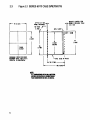
2.1 Series 6075 Dimensions. . . . . . . . . . . . . . . . . . .
4.1 Wiring Examples. . . . . . . . . . . . . . . . . . . . . .
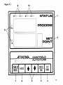
5.1 6075 Front Panel Features. . . . . . . . . . . . . . . . . .
5.2 Configuration Code Chart. . . . . . . . . . . . . . . . . . .
5.3 Ziegler - Nichols Graph. . . . . . . . . . . . . . . . . . . .
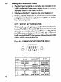
6.1 Connector Pin Identification. . . . . . . . . . . . . . . . . . . . .
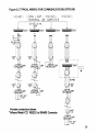
6.2 Wiring for Communications. . . . . . . . . . . . . . . . . .
4
6
8
13
17
23
28
29
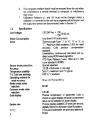
GENERAL INTRODUCTION
SECTION 1
1.1
General Description and Cautions
Athena Controls, Inc. is proud of the Series 6075 which you will now use It
has been manufactured to our exactingproduction standards, and packed
for maximum protection in shipment You will get years of reliable service
from the unit if the information in the manual is followed regarding location,
adjustments, and general operation.
CAUTlON
High Voltage and High Temperature can cause injury and are a
Fire Hazard. Please read all instructions, have only skilled professionals wire the unit, and use an approved temperature and/or
pressure safety control. Even the best components can be
damaged or may not failsafe.
Warning Notes:
1.
2.
3.
4.
5.
"B" Output for resistance load only.
An open thermocouple will disable the INDEX function.
Note also that in units utilizing only heating output the cooling gain
should be set by user to the equivalent heating gain. The inverse IS
also true.
A unique algorithm in the Model 6075 prevents continual buildup of
oscillation due to grossly misadjusted rate/reset (-rt-) or gain. When
this occurs the unit will control at some point higher or lower than set
point outside the proportional band. If this occurs -rt- was probably set
too low and/or gain set too high.
-rt- sets Rate (Derivative) and Reset (Integral) action. The number displayed is the Rate time in seconds. This is tracked by the Reset time in
seconds (1:6 ratio).
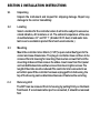
SECTION 2 INSTALLATION INSTRUCTIONS
2.1
2.2
Unpacking
Unpack the instrument and inspect for shipping damage. Report any
damage to the carrier immediitely.
Locating
Select a location for the controller where it will not be subject to excessive
shock vibration, dirt moisture or oil. The ambient temperature of the area
should be between 3 2 º and 131 º F (A model DC-15 dust, oil and water resistant cover is available to protect from harsh environments.)
2.3
Mounting
Mount the controller into a 92 mm (3 5/8”) square cutout See figure for the
cutout and case dimensions. The plug-in controller does not have to be
removed from its housing for mounting. Remove two screws that hold the
mounting slides and then remove the slides. Insert case from front panel
and re-installthe two slides and two screws. Do not over-tighten screws. The
length of the slides must be reduced if the controller is to be mounted in an
extra thick panel. If the controller has been unplugged from its housing, the
top of the housing can be determined because it features the serial tag.
2.4
Removing Unit
The 6075 can be removed from its housing by pulling firmly on the black
front bezel. If a communication port is connected, it should be removed
first
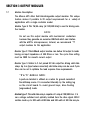
SECTION 3 OUTPUT MODULES
3.1
Module Description
The Athena 6075 offers field interchangeable output modules. This unique
feature makes it possible to fill output requirements for a variety of
applications with a single controller model.
Module Type B: This 7A/5A relay (at 120/240 Vac) is used for driving resistive heaters.
NOTE:
Do not use this output module with mechanical contactors
because they generate an excessive EMI field which can interfere
with the 6075’s microprocessor, Instead, we recommend “T’
output modules for this application
Module Type F: This 4-20mA output module can deliver full output to loads
having an input impedance of 500 Ohms or less. The cycle time setting
must be ZERO for smooth current output.
Module Type S: Similar to F. but pulsed 20 Vdc output for driving solid state
relays. Up to 6 (input series connected) solid state relays can be used. Cycle
time can be set to optimize the load response time requirements.
“F’ & “S” M O D U L E NOTE:
A push-on terminal is utilized as a return for ground currents of
the milliamp source. I t is connected internally by the mating lug
on the circuit board. To avoid ground loops, drive floating
(ungrounded) loads.
Module Type T: This solid state relay is capable of 1 amp at 120/240 Vac. It is
zero voltage switched and optically isolated from the drive signal. With it
resistive loads up to I20 watts at I20 Vac and 240 watts at 240 Vac may be
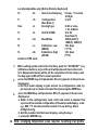
Standard Thermocouples
I.SA. Type
J
K
T
R
S
Materials
Color Code
Iron-Constantant (I/C)
White( + ) Red( - )
Chromel-Alumel
Yellow( + ) Red( - )
Copper-Constanan
Blue( + ) Red( - )
Platinum-Platinum 13%Rhodium Platinum-Platinum 10% Rhodium
-
Wiring RTD Circuits
6275 units are designed for 100 Ohm Platinum RTD’s 2-wire RTD’s are
connected to terminals 1and 2 with a jumper connecting 2 to 3. Keep leads
short and useheavygauge copper extension wires if necessary, to minimize
lead resistance. For long runs 3-wire RTD should be used and wire gauge
should be sufficient that resistance does not exceed 10 Ohms. An error of
0.2ºF will result for each additional 10 Ohms Per lead
DO NOT RUN RTD LEADS IN IN THE SAME CONDUIT AS POWER LINES.
If shielded RTD wire is used, terminate the shield only at the controller end,
using the comer screw provided for that purpose.
NOTE RTDs tend to be shock sensitive and require extra care in handling
and installation.
THERMOCOUPLE PLACEMENT (or RTD)
Proper thermocouple placement can eliminate many problems in the system. The probe should be placed so that it can detect any temperature
change with minimal thermal lag. In a process that requires fairly constant
heat output, the probe should be placed close to the heater. In processes
where heat demand is variable, the probe should be close to the work area.
Some experimenting with probe location is often needed to find its
optimum Position.
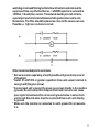
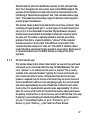
A WORD ON ELECTRICAL NOISE
Microprocessor are essentially small computers. As such they can
randomly be interferred with by large electrical spikes, even with elaborate
10
watchdog circuits and filtering built into the unit Contacts and coils must be
suppressed! One very effective filter is a .1 ufd/600V capacitor in series with a
100 Ohm, 1/2 watt (min.) resistor. This network must be put on all contacts,
especially across hard contacts that are switching coils and across the coils
themselves. The filter should be placed as close to the noise source as
Possible i.e. right on a contactors coil etc.
Other recommended practices include:
* Run sensor wires separately, shield if possible and ground only one end
of the shield.
* Install .01 ufd/100V or greater capacitors from each sensor terminal to
case ground (the green screw).
* Connect each unit’s ground (the green case screw) directly to the machine
(ground). Do not connect it to the panel Paint and corrosion can cause
poor signal transmission Do not connect ground wires in series from
unit to unit Ground wires must be connected from each unit directly
to ground
* Make sure the machine is connected to earth ground Do not assume
it is.
11
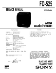
SECTION 5 OPERATION
5.1
Front Panel Features
Touch Key and Indication Operation Layout
1. Process Temperature or Parameter code is viewed on the upper
display.
2. Set Point or Parameter setting is viewed on the lower display. Degrees F
and C is also displayed.
3. Set Point Key: Allows user to return to set point
4. ENTER/TUNE Key: Enters a selected value into nonvolatile memory.
Also initiates Auto-Tuning when used in the correct sequence.
5. Up and Down Keys: Raises and lowers setting respectively. 2 Step scan
rate: Slow and Faster (after 5 seconds).
6. Index Key: Selects Parameters to be addressed
7. STAND-BY/CANCEL Key: Disables outputs. Unit is put in idle mode.
LED above switch lights in STAND-BY mode. STAND-BY is also used
as the position from which AUTO-TUNE is accessed. If the key is
pressed during Auto-Tuning the unit will cancel the Auto-Tuning procedure and return to the STAND-BY mode.
8. Receive (RX) and transmit (TX) lights: Indicate a signal is present at the
communication port tights only momentarily
9. Heat (HT) and CooI (CT) Output Lighk Lights when output drive signal
is present
10. Alarm Lights (A1 and A2): Lights when unit is in alarm. (programmable
Hi, Low, process or deviation.)
12
5.2
Basic Series 6075 Setup
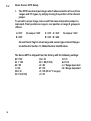
1.
The 6075 has dual-input ranges which allow selection of one of two
ranges and T/C types, by simply moving the position of the internal
jumper.
To set unit to proper range, remove unit from case and position jumper on
top board. Front position is range A, rear position is range B, grouped s
offered.
A = 01F
B = 02F
No Jumper = 26F
A = 33F A = 22F
B = 32F B = 26C
No Jumper = 22C
Consult Serial Tag for actual range and sensor type ordered. Ranges
are defined in Section 1.3, Model Number Identification.
The Series 6075 is shipped from the factory with the following settings:
SP = 100
A1 = 105
A2 = 95
rt = 00
HG = 30
HC = 05 (F=00) ct
14
CG = 30
CC = 05 (F=00)
cd = 08
AT = 00
cF = 08 (05 for ºC ranges)
ct = 00
Id = 01
bd = 02
cL = Range dependent
cH = Range dependent
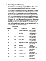
2.
R
. ange of Adjustments (Parameters)
All parameters are accessed by pressing the INDEX key. They are listed
in the order they are displayed when the lNDEX key is pressed.
The front panel of the Model 6075 contains a lower display of 5 digits
which displays the set point temperature, the other parameter values
and degrees F or C. The upper display consists of 4 digits which display
the process value or the parameter abbreviations; e.g. -A1- identifies
Alarm 1. As the INDEX key is pressed the second column abbreviations
appear in the upper display. To the right of the ENTER Key is an EXIT
Key labelled ‘SET POINT’ which allows the user to EXIT parameters 2
thru 16 back to parameter # 1 (set point). After changing a value the
ENTER Key must be pressed. This enters the new value in memory. If it
is not pressed and power is removed, the last value entered for that
parameter will be set up for that parameter.
DlSPLAYED
RANGE
NUMBER
CODE
PARAMETER
0
Process Temperature
Zero to span of
unit ( º F or ºC)
Zero to span of
Set Point
1
unit (ºF or ºC)
Zero to span of
2
-A1Alarm One
unit (ºF or ºC)
Alarm Two
Zero to span of
-A23
unit (ºF or ºC)
-rtRate/Reset (1:6 ratio) 0 to 255 Seconds
4
(See Note 6)
-HGHeat Gain
5
1 to 400
(See Note 2)
0 to 120 Seconds
-HCHeat Cycle Time
6
(See Note 7)
7
0 to 400
-CGCool Gain
(See Note 2)
0 to 120 Seconds
8
-CCCool Cycle Time
(See Note 7)
0 to 255
9
cdAccess Code
(See Note 3)
15
Locally Adjustable only (Not by Remote Keyboard)
0=Low, 1 =normal,
10
Auto-Tune Damping
-At2=High
11
-cFConfiguration
0 to15
(See Note 4)
0-Oil or none,
Cooling Type
12xx
-ct1 -Air, 2-Water
Unit ID CODE
0 to 99
13
-Id(See Note 5)
14
Baud Rates
-bd300(0),600(1)
1200(2), 2400(3)
15
-cLCalibration, Low
±3% Span
(ZERO)
(°F/ºC)
Calibration, High
16
±3% Span
-cH(SPAN)
(ºF/ºC)
xx Not on RTD units
3.
4.
5.
16
When setting up the unit for the first time, push the “STAND BY" key
(LED above button is on), and the unit will be placed into an idle condition. Outputs and alarms will be off. On completion of inital setup, push
the key again (LED off) for normal operation.
press the INDEX key until parameter #9 (-cd-) appears in the process
displayarea.
a. Set 14 in lower display to gain access to configuration code, by
pressing the up or down arrow and then pressing the ENTER key.
press the INDEX key until parameter #11 (-cF-) appears in the process
display area.
a. Refer to the configuration code chart and select a number that
represents the desired configuration of thealarms and display units
e.g., #06 = ºF, Deviation Alarms Alarm 1=Low Acting, Alarm
2=High Acting.
b. Set this number into the lower display, using the keys
c. press the ENTER key.
Note: Changing temperature scale requires re-setting of all points.
pressed the INDEX key, the unit will advance to the High and Low
Calibration positions. but index no further until the SETPOINT
key is depressed.
CAUTION: DO NOT CHANGE THE CALIBRATION LOW [cL(Zero)]
O R CALlBRATlON H I G H [cH(Span)] A D J U S T M E N T
UNLESS YOU INTEND TO, ARE QUALIFIED AND HAVE
A CALIBRATION TEST SETUP CONNECTED.
9. Press Index and Alarm One (Al) appears in the upper display area. If
this option is installed. set in the desired temperature value, then
press ENTER.
10. Repeat for (-A2-) Alarm two, if installed
11. Refer to the section on tuning the 6075 for the remainder of the
settings.
NOTE: When finished entering all parameters return to -cd- using the
INDEX key. Select the level of security desired and enter the appropriate
value into memory.
#1
- Allows changes to set point only.
#8
- Allows changes to first nine parameters only.
#14 - Allows changes to 9 parameters and calibration constants.
NOTE: Any other value only allows changes to -cdReference Notes
NOTE 1: Parameters # 10 thru #16 are accessed from the front panel only,
and can not be set from a remote terminal
NOTE 2: The gain value (-HG-&-CG-) is multiplier used to increase the sensitivity of the controller according to the formula: Output = Gain (E + I + D)
where E = Error. I = Integral. D= Derivative, Its relationship to proportional
band is as follows:
Unit Span
PROP BAND =
= Heat Gain (HG) or Cool Gain (CG)
___________________
18
Note that proportional band is an inverse function of gain, The range of
adjustment is 0 to 400 for Heat. 0 to 400 for Cool.
SPECIAL NOTE:
For Units utilizing only heating output, the cooling gain should be
set by the user to the equivalent heat gain. The inverse is also true.
Setting CG to 0 initiates an on-off (narrow deadband) output for
cooling, which is recommended for cooling-only applications.
Setting HG to 0 disables the Heat output.
NOTE 3: The access code is a number stored in ROM that upon entering in
location -cd- allows user access to change parameters. Depending on the
code entered the user may then alter calibration and configuration of the
controller. When this is accomplished the code may be changed to prevent
tampering with critical values. When the number is"1" only the set point can
be changed. When the number is ”8”, changes are allowed to the first nine
parameters. When the number is “14” all settings can be altered. When
neither 1, 8 or 14 are entered only the access code can be altered.
NOTE 4: The configuration code allows the user to configure the alarms for
process/deviation, high or low energizing. The code also selects ºF or ºC
operation of the unit. SEE THE CONFIGURATlON CODE CHART.
NOTE 5 : -Id- is the unit identification code. It is variable from 00 thru 99 and
is used with the communications interface to allow a remote device to identify which controller it is communicating with.
NOTE 6: Setting RT to 0 disables rate and reset action for proportional only
control. This will cause an offset between set point and process
termperature.
NOTE 7: Set the heat cycle (-HC-) and cool cycle (-CC-) according to power
handler being used. 0 for "F" (4-20mAdc) outputs, 5-20 for contactors and
solenoids. Setting HC or CC to 0 initiates 200 millisecond timebase for fast
cycling of the respective output. Use with external solid state relays (“S"
Modules) or SCR Power Controllers ("F" Modules).
19
5.3
Tuning the Controller
5.3.1
Introduction
The Series 6075 is a state-of-the-art automatic tuning PlD temperature controller. The user has the option of automatically selecting the controller’s
PlD settings or manually setting the unit as desired.
Tuning a 3-Mode controller involves three (3) major adjustments; proportional Band (Gain), Rate (Derivative) and Reset (lntegral) action. Athena has
simplified the adjustment procedure with the incorporation of the Rate and
Reset settings into one adjustment "RT" which is displayed in seconds of
Rate time. The Reset time is automatically set at six (6) times the displayed
Rate values.
Automatic PlD Tuning procedure
5.3.2
NOTE FOR OPTlMUM RESULTS
1. Set point must be a minimum of 100°F above the starting or ambient
temperature when tuning is initiated for accurate tuning. Less than
2. 100ºF may not yield effective tuning settings.
Multi-zone applications require Auto-Tune units on each zone and
simultaneous warmup.
3. Loss of power or a turn-off during the Auto-Tune cycle requires a restart
from ambient (or at least I00ºF rise to set point) for reliable PlD
values.
4. Change of state processes, i.e. solid to liquid or liquid to gas, may
introduce erroneous tuning parameters during process warmup.
Tuning should be done after the change has occured
5.3.2.1
20
Damping Settings
Heat Damping Choices (“-At-“: position # 10)
To allow the controller to provide automatic tuning for a wide variety of processes that may exhibit varying heating characteristics and/or varying heating capabilities, the controller offers three damping choices:
00 Low Damping - For processes that (any combination of the following)
- are adequately powered with excellent coupling between heater and
probe.
- require quick response and the tightest possible temperature control
is desired
01 Normal Damping - For processes that: (any combination of the
following)
- have heaters that are properly sized.
- have good coupling between heater and probe.
- are considered standard with moderate lags and response time.
0 2 High Damping - For processes that (any combination of the following)
- are overpowered
- have multiple lags
- are poorly coupled between the heater and probe
COOL (“ct-“: position #12) (Not On RTD Units)
When using the controller on heating and cooling applications, such as
extruders, the "ct" number allows setting of the controller for the type of
cooling used:
00 - Oil cooling (Use this Setting if No cooling is used)
01 - Air cooling - Forced air
02 - Water cooling (above 212ºF set point)
5.3.2.2
Operating Instructions (Read “Damping Settings” before proceeding)
How to Start the Automatic Tunina procedure
STEP 1: Energize the unit and Proceed immediately to step 2.
STEP 2: Place the unit on standby by pushing the stand-by button. LED
above button will light Auto-tune can only be accessed from the
stand-by position.
STEP 3: Index down and enter access code, position 9, then press set
point
STEP 4: Index down and enter all settings per section 5.2 Basic Setup. e.g.
set point Al, A2, HC, CC, AT, cF, ct, Id, bd, and press set point RT,
HG, and C G will be set by controller during Auto-Tuning.
STEP 5: Index down to “-At-“.
21
STEP 6: When ready to start Auto-Tuning calculation of PlD settings press
the “Enter/Tune” button. The displays will return to process and
set point displayed. The F/C digit will blink while tuning is in process. Upon completion of tuning, the digit will stop blinking. TO
stop the Auto-Tuning press standby/cancel.
NOTE:
Series 6275, RTD input will not Auto-Tune when the decimal point
range is used. If tenth degree range is desired either auto tune on
the other range and then move the range jumper or use manual
tuning methods.
How to override automatic tuning parameters
Nichols Tuning Method)
(Also refer to Ziegler-
It is possible to set or fine tune the three mode parameters manually.
To manually enter parameters
1) Press Index button until "Rt"(Rate), "HG" (Heat Gain) or CG (Cool Gain)
are displayed.
2) Enter new parameter setting desired using the up/down buttons.
3) Press the “Enter” key.
The new parameters will now take control of the process.
5.3.3
22
Manual Tuning procedure
The following procedure can be used for fine tuning after or instead of AutoTuning.
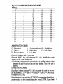
Ziegler-Nichols PID Tuning Method
This has long been an accepted method of tuning PID (3 Mode) controllers
using a minimum of time and set up to reach effective tuning parameters.
Before proceeding make sure the basic unit setup is done as discussed in
section 5.2.
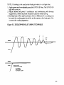
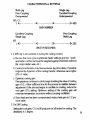
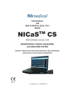
4. Press STAND-BY again and temperature will begin to rise. When the process rises to the desired set point it will probably oscillate. Periodically
decrease the Gain (lower the HG number) until a small constant oscillation is obtained. Reducing the Gain by steps of one half (1/2) the previous
-HG- setting is an acceptable method to obtain the desired small oscillation. Note time between oscillations in seconds (“T” on Figure 5.3).
5. Decrease the Heat Gain to 60% of the value obtained in the previous step.
The Gain is now tuned. Enter the same number in the Cool Gain.
6. The best rate time (-RT-) setting is one-eighth (1/8) the time in seconds of
one cycle (see cycle time "T" in Figure 5.3). This will give a conservatively
tuned system. If faster response and/or faster rise to set point is desired
one-twelth (1 /12) of "T" may be used. Note that faster settings may yield
instability and temperature overshoots on startup. Remember that the
reset automatically tracks the rate (-rt-) adjustment
7. Connect cooling apparatus Observe control stability.
8. If oscillation occurs lower the cool gain number. If cooling is sluggish
raise the cooling gain number.
NOTE: In order to observe changes in process temperature, especially as
they relate to time, it is helpful to use a temperature recorder in conjunction
with all tuning and parameter setting procedures.
TUNING HINTS
1. Once the optimum -rt- and -HG- have been set into the unit, cold start tests
of the process should be tried. Remember that start-up and running
parameters will usually be different and it is desirable to adjust both gain
(HG) and rate/reset (RT) ±25% to strike a balance between good startup
and running settings.
Generally higher settings of -rt- will give more controlled start-ups with
less overshoot lower values will give faster recovery from process upsets
Higher gain settings will give tighter control of the running process. but
may give more overshoot on start-up.
24
SECTION 6 COMMUNICATIONS
6.1
Communications Modules
Optional plug-in modules are available for the Series 6075 to allow interfacing to the most common industry standards. A brief description of each type
follows.
6.1.1
RS485
RS485 is a specification standard for balanced voltage digitial interface circuits published by the EIA.
It was published in 1983 as an upgrade of RS422A electrical specifications,
with emphasis given to the application of multipoint systems. The interface
circuits used in the Athena Model 6075 meet the electrical characteristics of
the RS485 standard.
The RS485 multipoint capability allows up to thirty-two (32) units to be connected together in a half duplex network More can be added with the use of
“repeaters” such as the Athena Model CC.1 interface box
This module allows bi-directional data transfer over a shielded twisted pair.
The twisted pair is a transmission line with drops to communicating devices.
Since it is a transmission line, terminating resistors are required at the most
distant ends of the line to minimize reflections. (Typically 60 ohms from
each line to signal ground). The Model 6075 RS485 module is fully optically
isolated, eliminating ground loop problems, Parallel drops from the
transmission line should be kept as short as possible. Alternately the line
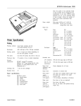
could be daisy chained at each DB-9 connector. Note that the polarity of the
line is important and each device will specify an “A” and ”B” connection. On
the 6075 RS485 module, “A" is pin 8 and 4; “B” is pin 7 and 3 and communications ground is available on pins 1,2, and 6. Frame ground is pin 5
and 9.
6.1.2
RS232C
The RS232C is a standard that was published in 1968 by the “Electronic
Industries Association” (ElA). The RS is an acronym for Recommended
26
Standard and the 232 is the identification number for that particular Standard. The C designates the last revision made to the RS232 standard. The
purpose of this standard is to define the electrical characteristics for the
interfacing of ”data terminal equipment” and “data communications equip
ment”. The standard providesvoltage ranges for data and control signals to
provide proper transmission.
This module allows bi-directional data transfer via a three conductor cable
consisting of signal ground (pin 7). receive (input, pin 2) and transmit (output, pin 3). It is recommended for less than fifty feet between computer/
terminal and instrument Note that multiple instruments cannot be tied to
the same port The module is optically isolated to eliminate ground Ioop
problems. Note that in a typical installation, “data out” of the computer/
terminal connects to "receive data" of the 6075 and "receive data" of the
computer/terminal connects to *‘data out” of the 6075. If shielded cable is
used it should be connected to frame ground at one end only. Signal ground
is connected at both ends. The RS232 module is configured for active
operation.
6.1.3
20 mA Current Loop
This module allows bi-directional data transfer via a current loop with each
instrument series connected within the loop (10 Units Maximum). The module is “passive” i.e. an external current source is required. This is usually
available at the computer/terminal. Typically the receive and transmit section of each instrument is series connected and inserted into the loop:
however a separate loop for receive and transmit may be used in the event
there is insufficient headroom in the energizing supply. For series transmit
and receive approximately two volts of headroom is taken for each instrument on line. For operation with separate loops, approximately 1.5 volts is
taken for receive and 0.5 volts for transmit Care must be observed to insure
the polarity of connections is correct because current will still flow in the loop
if polarity is reversed making troubleshooting difficult Wiring connections
are: pin 3 = Transmitting Position (+), pin 4 = Transmit (-), pin 7 =
Receive (+), pin 8 = Receive (-), pins 5 and 9 are Frame Ground.
27
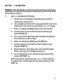
SECTION 7 CALIBRATION
WARNING: These adjustments are factory set and should only be changed by a
qualified person using calibrated equipment. Adjustment is not necessary during
the life of these controllers.
7.1
Zero (-cL-) and Span (cH) Calibration
1. Unlock access to the calibration constants by entering the unlock
number (14) into location 9 (-cd-).
2. Use a tempemture calibmtor with a range appropriate for the unit to be
calibrated. Set in the value for low scale calibration, e.g. (1 % of range).
3.
4.
5.
6.
Step to -cL- (calibmte low [ZERO]) using tie index key on the 6075.
press the up/down keys on the 6075 until both instruments agree
press the ‘ENTER’ key.
Set in a value on the calibrator equivalent to the high-end capability of
the unit under test e.g. (95% of range).
Step to -cH- (calibrate high [SPAN]) using the INDEX key.
7.
Press the up/down keys on the 6075 until both instruments agree.
Press the "ENTER" key.
8. Repeat steps2 thru 7 until readings agree. Some interaction between
Zero(-cL-) and Span (-cH-) calibration usually occurs
9. Lock out configumtion access, if desired, and return to set point by
pressing "SET POINT" key.
NOTE: Pressing index continuously selects -cH- or -cL- (Span and Zero) in
the calibrate mode to faciliite testing. Exit this mode by pressing the ‘SET
POINT" key.
33
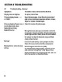
SECTION 8 TROUBLESHOOTING
8.1
Troubleshooting - General
Symptom
Probable Cause & Corrective Action
Display does not light up.
No power, blown fuse.
Process display shows (- - -)
Open thermocouple circuit Shorting terminals 1
or ‘HHHH’
and 2 should indicate temperature at back of case.
Repair or replace thermocouple.
Process display shows LLLL or Check for reversed thermocouple.
counts down scale when
temperature is rising.
About 30% error.
Wrong thermocouple type connected or internal
range jumper in wrong position. Check serial tag for
sensor type and then check probe. Consult manual
for jumper location for desired range and then
check unit and sensor.
No heat
Incorrect heater wiring, wrong output module.
Check for cause and correct the components
Display blinks; entered values Electromagnetic interference (EMI).
change.
To eliminate high voltage spikes, separate sensor
and controller wiring from “dirty” power lines.
Ground heated devices. Suppress all coils and contacts. See section on Electrical Noise.
34
ATHENL
Athena Controls, Inc. 5145 Campus Drive Plymouth Meeting, PA 19462
Tel: (610) 828-2490 Fax: (610) 828-7084