1
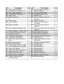
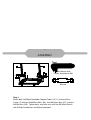
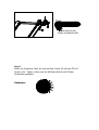
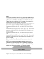
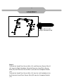
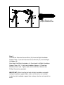
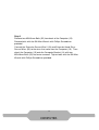
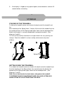
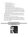
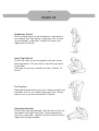
Manual Treadmill with Pulse OWNER’S Item #1005 MANUAL TABLE OF CONTENTS SERVICE 2 IMPORTANT LABELS 3 PRODUCT SAFETY 4 PART DRAWING 5 PART LIST 6 HARDWARE PACKING LIST & TOOLS 8 ASSEMBLY 9 COMPUTER 16 STORAGE 17 ADJUSTMENTS 18 LUBRICATION 19 TROUBLE SHOOTING & MAINTENANCE 20 WARM UP 21 WARRANTY 22 1 SERVICE IMPORTANT: FOR NORTH AMERICA ONLY To request product service and order replacement parts, please call our customer service department at: 18669241688 Please have the following information ready when requesting for service: Your name Phone number Model number Serial number Part number Proof of Purchase *Before returning this product to the store please contact customer service at the contact number. Paradigm Health & Wellness, Inc. 1189 Jellick Ave, City of Industry, CA 91748, USA 2 IMPORTANT LABELS 3 PRODUCT SAFETY Basic precautions should always be followed, including the following safety instructions when using this manual treadmill: Read all instructions before using this manual treadmill. 1. Check every part of the equipment before exercise. If there is any defective component, replace it immediately; keep the equipment out of use until repair. 2. Make sure all parts, bolts and nuts are well assembled and locked before exercise. 3. Never insert any object into any opening. 4. Never operate this manual treadmill if it is not working properly. If it has been dropped or damaged, or been exposed to water, return the appliance to a service center for examination and repair. 5. Do not attempt any maintenance or adjustments other than those described in this manual. Should any problems arise, discontinue use and consult an Authorized Service Representative. 6. Wear comfortable and suitable clothing when using the treadmill. Do not use the treadmill barefoot, in only socks or in sandals, always wear athletic shoes. Never wear loose clothing because it could run the risk of getting caught in the treadmill. 7. Keep children and pets away from the equipment while in use. 8. Do not use the treadmill outdoors. This manual treadmill is for household use only. 9. Only one person should be on the treadmill while in use. 10. Keep the manual treadmill on a solid, level surface with the minimum safety area clearance of 78.7” x 118” of the manual treadmill. Be sure the area around the treadmill remains clear during use and has adequate clearance. 11. Hold the handlebar with your hands when starting or stopping exercise and increasing or decreasing the speed. 12. If feeling chest pains, nausea, dizziness, or short of breath, you should stop exercising immediately and consult your physician before continuing. 13. The maximum weight capacity for this product is 260 lbs. WARNING: Before beginning any exercise program consult your physician. This is especially important for the persons who are over 35 years old or who have preexisting health problems. Read all instructions before using any fitness equipment. CAUTION: Read all instructions carefully before operating this product. Retain this Owner’s Manual for future reference. 4 PART DRAWING 5 PART LIST No. 001 002 003 004 005 006 Description Rear Roller Ø60x395 Running Deck 1020x407x12 Front Roller Ø60x395 Running Belt 2400x335x1.2 Main Frame Protective Cover Qty 1 1 1 1 1 1 007 Base Frame 008 Left Handlebar 1 1 009 Right Handlebar 1 010 Left Handlebar Support Tube 1 011 012 013 014 015 016 1 2 2 1 1 2 Right Handlebar Support Tube Hand Pulse Sensor with Wire Handlebar Adorner Computer Bracket Ø28 Computer (HR1566SP) Rear Roller Adjustment Bolt Plate 017R Right Incline Adjuster 017L Left Incline Adjuster 018 Incline Adjuster End Cap Ø50 019 Incline Adjuster End Cap Ø38 020 Locking Pin Ø8x60 021 Main Frame End Cap T65x25 022 Square End Cap (□25.4) 023 Square End Cap (□20) 024 Safety Tube A (□20x500) 025 Safety Tube B Bushing (F23xF20.3x42) 1 1 2 2 2 3 3 2 1 1 No. 026 027 028 029 030 031 Description Qty Safety Tube B (□25x460) 1 Spring Knob Ø8 1 Transport Wheel Ø50 2 Square End Cap (□38) 2 Rubber Pad 4 Extension Sensor Wire III 1 (180mm) 032 Sensor with Wire 1 033 Extension Sensor Wire I 1 (1250mm) 034 Extension Sensor Wire II 1 (250mm) 035 Extension Hand Pulse Sensor Wire 2 (250mm) 036 Wire Plug (Ø6xØ21x10) 1 037R Right Side Rail (950mm) 1 037L Left Side Rail (1020mm) 1 038 Magnet with Magnet Bracket 1 039 Screw ST3x6 2 040 Rear Roller Adjustment Bolt 2 M6x50mm 041 Hexagon Head Bolt M6x25 6 042 Screw ST4x16 8 043 Bolt M8x40mm 5 044 Bolt M8x35mm 1 045 Bolt M8x45mm 4 046 Bolt M8x55mm 4 047 Bolt M8x16mm 4 048 Washer Ø12.5xØ22 3 049 Sleeve Ø16xØ12.5x9mm 1 050 Bolt M10x55mm 2 6 PART LIST No. Description 051 Handlebar Support Tube End Cap Ø28 052 Bolt M5x10mm 053 C Clip Ø12 054 Nylon Washer Ø8.2xØ16x2T Qty No. Description 2 058 Screw ST3x12 055 Washer M6 056 Spring Washer M6 057 Nylon Nut M8 8 6 10 2 3 2 059 Washer M8 060 Washer M10 061 Computer Bracket Foam Grip Ø23x3Tx390 062 Handlebar Foam Grip Ø23x3Tx580 063 Screw ST4x12 Qty 2 6 2 2 2 2 (45) Bolt M8x45mm 4 PCS (46) Bolt M8x55mm 4 PCS (47) Bolt M8x16mm 2 PCS (50) Bolt M10x55mm 2 PCS (57) Nylon Nut M8 4 PCS (59) Washer M8 4 PCS 7 HARDWARE PACKING LIST & TOOLS (60) Washer M10 (63) Screw ST4x12 2 PCS 2 PCS Allen Wrench with Phillips Screwdriver 5M 1 PC Wrench 1 PC Allen Wrench 6M 1 PC 8 ASSEMBLY Tool: Allen Wrench with Phillips Screwdriver 5M Wrench Step 1 Attach both Left/Right Handlebar Support Tubes (10, 11) onto the Base Frame (7) with four M8x55mm Bolts (46), four M8 Nylon Nuts (57), and four M8 Washers (59). Tighten bolts and nylon nuts with the 5M Allen Wrench with Phillips Screwdriver and Wrench provided. NOTE: PLEASE DO NOT FULLY TIGHTEN HARDWARE IN STEP 1 UNTIL STEP 5 IS COMPLETED. Hardware: (46) Bolt M8x55mm 4 PCS (57) Nylon Nut M8 4 PCS 9 ASSEMBLY (59) Washer M8 4 PCS Tool: Allen Wrench with Phillips Screwdriver 5M Step 2 Attach the Protective Cover (6) onto the Main Frame (5) with two ST4x12 Screws (63). Tighten screws with the 5M Allen Wrench with Phillips Screwdriver provided. Hardware: (63) Screw S4x12 2 PCS . 10 ASSEMBLY Tool: Wrench Allen Wrench 6M Allen Wrench with Phillips Screwdriver 5M Step 3 Lift the front end of Main Frame (5) up by two or more people and then attach the Main Frame (5) onto the Left/Right Handlebar Support Tubes (10, 11) with two M10x55mm Bolts (50) and two M10 Washers (60). Tighten bolts with the 6M Allen Wrench provided. Please do not fully tighten the bolts until the handlebars are installed. Connect the Sensor Wire (32) from the Main Frame (5) to the Extension Sensor Wire I (33) from the Right Handlebar Support Tube (11). Remove one M8x35mm Bolt (44), one Ø8.2xØ16x2T Nylon Washer (54), and one M8 Nylon Nut (57) from the Safety Tube A (24). Remove bolt and nylon nut with the 5M Allen Wrench with Phillips Screwdriver and Wrench provided. Remove one M8x40mm Bolt (43), one Ø8.2xØ16x2T Nylon Washer (54), and one M8 Nylon Nut (57) from the Safety Tube B (26). Remove bolt and nylon nut with the 5M Allen Wrench with Phillips Screwdriver and Wrench provided. Fold up the Main Frame (5) and hold it by one person, release the Spring Knob (27) by the other person and pull the Safety Tube A (24) to stretchedout. Attach the Safety Tube B (26) onto the Lplate on the Base Frame (7) with one M8x40mm Bolt (43), one Ø8.2xØ16x2T Nylon Washer (54), and one M8 Nylon Nut (57) that were removed. 11 ASSEMBLY Tighten bolt and nylon nut with the 5M Allen Wrench with Phillips Screwdriver and Wrench provided. Attach the Safety Tube A (24) onto the Main Frame (5) with one M8x35mm Bolt (44), one Ø8.2xØ16x2T Nylon Washer (54), and one M8 Nylon Nut (57) that were removed. Tighten bolt and nylon nut with the 5M Allen Wrench with Phillips Screwdriver and Wrench provided. NOTE: It is recommended that you always use the aid of a second person when assembling the treadmill. Hardware: (50) Bolt M10x55mm 2 PCS (60) Washer M10 2 PCS 12 ASSEMBLY Tool: Allen Wrench with Phillips Screwdriver 5M Step 4 Connect the Hand Pulse Sensor Wire (12) and Extension Sensor Wire III (31) from the Right Handlebar (9) to the Extension Hand Pulse Sensor Wire (35) and Extension Sensor Wire II (34) from the Computer Bracket (14). Connect the Hand Pulse Sensor Wire (12) from the Left Handlebar (8) to the Extension Hand Pulse Sensor Wire (35) from the Computer Bracket (14). Then install the Computer Bracket (14) to both Left/Right Handlebars (8, 9) by inserting the Computer Bracket (14) onto both Left/Right Handlebars (8, 9), using two M8x16mm Bolts (47). Tighten bolts with the 5M Allen Wrench with Phillips Screwdriver provided. IMPORTANT: While installing the computer bracket onto the right and left handlebars, make sure the wires are installed inside the right and left handlebars and pay attention not to pinch the wires. Hardware: (47) Bolt M8x16mm 2 PCS 13 ASSEMBLY Tool: Allen Wrench with Phillips Screwdriver 5M Step 5 Connect the Extension Sensor Wire I (33) from the Right Handlebar Support Tube (11) to the Extension Sensor Wire III (31) from the Right Handlebar (9). Attach both Left/Right Handlebars (8, 9) onto both Left/Right Handlebar Support Tubes (10, 11) with two Handlebar Adorners (13) and four M8x45mm Bolts (45). Tighten bolts with the 5M Allen Wrench with Phillips Screwdriver provided. IMPORTANT: While installing the both left/right handlebars onto both left/right handlebar support tubes, make sure the wires are installed inside the right handlebar support tube and pay attention not to pinch the wires. NOTE: PLEASE FULLY TIGHTEN ALL HARDWARE INSTALLED IN STEP 1 TO STEP 5 WITH THE TOOLS PROVIDED. Hardware: (45) Bolt M8x45mm 4 PCS 14 ASSEMBLY Tool: Allen Wrench with Phillips Screwdriver 5M Step 6 Remove two M5x10mm Bolts (52) from back of the Computer (15). Remove bolts with the 5M Allen Wrench with Phillips Screwdriver provided. Connect the Extension Sensor Wire II (34) and Extension Hand Pulse Sensor Wires (35) to the wires that come from the Computer (15). Then attach the Computer (15) onto the Computer Bracket (14) with two M5x10mm Bolts (52) that were removed. Tighten bolts with the 5M Allen Wrench with Phillips Screwdriver provided. 15 COMPUTER Key functions: MODE: Display function selection. Press and hold the MODE key for 2 seconds, all data values will clear to zero except the ODO (ODOMETER) data values. SET: To set goal values as exercise target. RESET: To clear data and goal values. AUTO ON/OFF: When you start to exercise or press any key on the computer, the computer will turn on. If you leave the equipment for 4 minutes, the power will turn off automatically. Display functions: SCAN Automatically scans through each display mode. TIME Displays your elapsed workout time in minutes and seconds. SPEED Displays the current speed. DISTANCE Displays distance of exercise sessions. CALORIES Displays calories burned during exercises. (This data is a rough guide for comparison of different exercise sessions and should not be used in medical treatment). ODOMETER Displays accumulative distance from combined exercise sessions. PULSE Display the BPM (Beats per Minutes). Set a goal value: You can set an exercise goal, the value will be counted down for the value you set. Press MODE to select a value you’d like to set. Press SET to set the value, then start your exercise. How to install the batteries: 1. Remove the battery cover at the rear of computer. 2. Place two "SIZEAAA" batteries into the battery housing. 3. Insure batteries are correctly positioned and battery springs are in proper contact with batteries. 4. Reinstall the battery cover. 5. If the display is illegible or only partial legible, remove batteries and wait 15 seconds before reinstalling. 16 STORAGE FOLDING UP THE TREADMILL To fold up the treadmill, place one hand on the back end of the treadmill and the other hand to pull the Spring Knob. Carefully lift the end of the treadmill up into the upright position until the Spring Knob "pops" down into the locked position. Make sure the deck is securely locked before moving the treadmill. (See diagrams A and B.) The unit can be carefully tilted onto its transport wheels for easy moving and storage. Store the treadmill in a clean and dry environment away from children. A B Spring Knob SETTING DOWN THE TREADMILL To set down the treadmill, place one hand on the back end of the treadmill and the other hand to pull the Spring Knob, then carefully lower the deck to the ground until the Spring Knob "pops" down into the locked position. (See diagrams C and D.) Note: Do not stand under the deck when setting down the treadmill. TO PREVENT INJURY PLEASE MAKE SURE YOU HAVE A FIRM HOLD WHEN LIFTING UP OR SETTING DOWN THE DECK. C D Spring Knob 17 ADJUSTMENTS Adjusting the Incline Adjuster Place one hand on the rear end of the Main Frame, then lift the rear end of the Main Frame up and use the other hand to remove the Locking Pin. Adjust the Incline Adjuster to the desired position and insert the Locking Pin into the holes on the Main Frame and Incline Adjuster to lock the Incline Adjuster in place. NOTE: Make sure when adjusting the incline angle of the Incline Adjuster that both Incline Adjusters should be adjusted to the same angle. Using the Incline Adjusters at different angles can cause the treadmill to be unstable and cause injury. Adjusting the Running Belt 1. The running belt is initially set and adjusted at the factory. However it may come loose during transportation and/or during use. After prolonged use, the belt will begin to stretch out. 2. If the running belt begins to shift to either left or right side, the user can stand on the main frame and hold the handlebars with both hands. Then use your right or left foot to run on the side of the running belt that is opposite to the direction of the slip. 3. If the belt begins to slip to the left use your right foot on the right side. You should see the belt start to correct itself by moving back towards the center. However, if the running belt is still shifting away from center, use the 5M Allen Wrench with Phillips Screwdriver provided and turn the left or right Rear Roller Adjustment Bolt 1/2 turn in a clockwise direction (turn the same side bolt that matches the direction of the slip). Then try running on the center of the running belt again. If the running belt is still shifting away from center, turn the same Rear Adjustment Bolt another 1/4 turn in the clockwise direction. You should see the belt start to correct itself by moving back towards the center. Repeat this procedure until the running belt is centered. If the running belt is slipping during use, then use the 5M Allen Wrench with Phillips Screwdriver provided and turn both the left and right rear roller adjustment bolts 1/4 turn in the clockwise direction. You should now run on the running belt to determine if the running belt is still slipping. Repeating the above procedure until the running belt is not slipping. 18 LUBRICATION The treadmill has already been spread with "Silicone Oil" in advance before leaving the manufacturing plant. Silicone oil is without volatility and has gradually permeated through the running belt. There will be no need to respread the oil in normal circumstances. "Silicone Oil" may be respread once the resistance has been increased and the running belt starts rubbing against the running deck. To hold open the running belt from two sides, apply the silicone oil with an even motion on the center of the running deck. Allow the silicone oil to ‘set’ for one minute before using the magnetic treadmill. Attention: Only use "Silicone Oil" lubricants for this equipment. In addition, do not add any other oil ingredient; otherwise the magnetic treadmill will be damaged. Do not overlubricate the running deck. Excess lubricant should be wiped off with a clean towel. 19 TROUBLE SHOOTING & MAINTENCE TROUBLE SHOOTING PROBLEM: Treadmill running belt slips or is not centered on rear roller. SOLUTION: Refer to “Adjusting the Running Belt” section on page 18. PROBLEM: Computer not working correctly SOLUTION: Check to make sure the computer wires are connected securely. SOLUTION: Check the batteries are correctly positioned and battery springs are proper contact with batteries. SOLUTION: Make sure the batteries are not dead. PROBLEM: There is no heart rate reading or heart rate reading or is erratic / inconsistent. SOLUTION: Make sure that the wire connections for the hand pulse sensors are secure. SOLUTION: To ensure the pulse readout is more precise, please always hold on to the handlebar grip sensors with two hands instead of just with one hand only when you try to test your heart rate figures. SOLUTION: Gripping the hand pulse sensors too tight. Try to maintain moderate pressure while holding onto the hand pulse sensors. PROBLEM: The manual treadmill makes a squeaking noise when in use. SOLUTION: The bolts may be loose on the treadmill, please inspect the bolts and tighten the loose ones. MAINTENANCE Cleaning The manual treadmill can be cleaned with a soft cloth and mild detergent. Do not use abrasives or solvents on plastic parts. Please wipe your perspiration off the manual treadmill after each use. Be careful not get excessive moisture on the computer display panel as this might cause an electrical hazard or electronics to fail. Please keep the manual treadmill, specially, the computer console, out of direct sunlight to prevent screen damage. Please inspect all assembly bolts on the machine for proper tightness every week. Storage Store the manual treadmill in a clean and dry environment away from children. 20 WARM UP Quadriceps Stretch With one hand against a wall for balance, reach behind you and pull your right foot up. Bring your heel as close to your buttocks as possible. Hold for 15 counts and repeat with left foot up. Inner Thigh Stretch Sit with the soles of your feet together with your knees pointing outward. Pull your feet as close into your groin as possible. Gently push your knees towards the floor. Hold for 10 counts. Toe Touches Slowly bend forward from your waist, letting you back and shoulders relax as you stretch toward your toes. Reach down as far as you can and hold for 15 counts. Hamstring Stretches Sit with your right leg extended. Rest the sole of your left foot against your right inner thigh. Stretch toward your toe as far as possible. Hold for 15 counts Relax and then repeat with left leg extended. 21 WARRANTY Paradigm Health & Wellness, Inc. warrants to the original purchaser that this product is free from defects in material and workmanship when used for the purpose intended, under the conditions that it has been installed and operated in according to Paradigm’s Owner’s Manual. Paradigm’s obligation under this warranty is limited to replacing free of charge, any parts which may prove to be defective under normal home use. This warranty does not include any damage caused by improper operation, misuse or commercial application. From the date of purchase, the product is warranted to be free from defects for 3 (three) year. All parts and workmanship, including upholstery, foam, ball bearings, pulleys, cables, shocks, all tension mechanisms, wheels, pedals and hardware are to be free from defects for 90 days. This warranty is offered only to the original owner and is not transferable. Proof of purchase is required. This warranty is offered only to the original owner and is not transferable. Ordering Replacement Parts Replacement parts can be ordered by calling or emailing our customer service department 18669241688 Monday through Friday, 8:00 AM 5:00 PM (PST). When ordering replacement parts please have the following information ready: 1. Owner’s Manual 2. Model Number 3. Description of Parts 4. Part Number 5. Date of Purchase