1
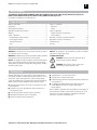
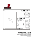
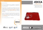
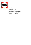
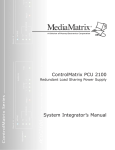
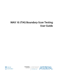
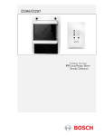
RMDC Series Installation Instructions 52-376 Rev B01
Rack Mount DC Power Supplies
Operating and
Installation
Instruction Manual
Includes PS5-M Power Supplies &
FAI Accessory Boards
MEA
Approved
AlarmSaf, Inc.
65A Industrial Way, Wilmington, Massachusetts 01887
978-658-6717 800-987-1050
www.alarmsaf.com
RMDC Series Installation Instructions 52-376 Rev B01
2
MODEL NUMBERS
THIS MANUAL COVERS MODEL NUMBERS: RMDC-PS5-M, RMDC-PS5-M-UL-FAI, RMDC-1248(F), RMDC-PS5-M-8(F)-UL-FAI,
RMDC-PS5-MD, RMDC-PS5-MD-UL-FAI, RMDC-12416(F), RMDC-PS5-MD-16(F)-UL-FAI
Full product list available at www.alarmsaf.com
TABLE OF CONTENTS
Warnings and Notices ..................................................................2
Introduction..................................................................................2
RMDC Model Descriptions ............................................................3
Applicable Standards & Documents...............................................3
Warranty ......................................................................................3
Section 1: Overview ......................................................................4
Electrical Ratings & Specifications ..............................................4
Power Supply Drawing ..............................................................4
Terminal Descriptions.................................................................5
Fuses ........................................................................................5
Section 2: Installation....................................................................6
Mounting..................................................................................6
Wiring.......................................................................................6
Section 3: Operation.....................................................................7
Jumper and Switch Configuration..............................................7
Visual Indicators ........................................................................9
Appendix A: FAI Input Connection Methods ...............................10
Appendix B: Enclosure CAD Drawing ..........................................11
Troubleshooting..........................................................................12
Glossary......................................................................................13
WARNINGS AND NOTICES
WARNING: To reduce the risk of fire or electric shock, do not expose
these products to rain or moisture.
WARNING: Installation and all servicing should be made by qualified
service personnel and should conform to all local codes.
NOTICE: This equipment shall be installed in a manner which protects
against unintentional operation by employees or other personnel
working about the premises, damage from falling objects, building
vibration or other causes.
NOTICE: This equipment is not intended for use within the patient
care areas of a health care facility.
SYMBOL DEFINITIONS
WARNING: Read the instruction manual to avoid
personal injury or property damage.
WARNING: Risk of electric shock. Service to be
performed by a qualified service person.
INTRODUCTION
AlarmSaf Rack Mount DC Power Supplies supply regulated and
filtered main, standby or auxiliary power to access control, CCTV, fire
and security systems and components. Single and Dual Voltage
systems are available with fuse protected or power limited outputs
and/or fire alarm interface capability. Product features include:
Illuminated master power switch with circuit breaker to control
primary power.
Computer style 3-wire grounded line cord for connection to
primary power source.
Screw-secured plug-in terminal strips for field wiring
Removable face plate for ease of serviceability
Enhanced surge and transient protection.
Standard EIA 19”, 2U rack mount chassis.
External LEDs to indicate output status
Individual output protection using either automotive blade fuses
or resettable PTCs.
Compatible with AlarmSaf Rack Mount Battery Enclosure
(model #RMBE-1224-4B7) for single or dual voltage
battery back-up
When installed in accordance with all standards listed on page 3 of
this document, the RMDC series provides DC power for DC CCTV
cameras, access control equipment, IT equipment and related
accessories, or other DC powered devices.
AlarmSaf, Inc. 65A Industrial Way, Wilmington, MA 01887 978-658-6717 www.alarmsaf.com
RMDC Series Installation Instructions 52-376 Rev B01
3
RMDC MODEL DESCRIPTIONS
SINGLE VOLTAGE SYSTEMS
All single voltage systems use one power supply, user selectable for
12VDC, 8A or 24VDC, 4A.
RMDC-PS5-M: Single voltage, single output system.
RMDC-PS5-M-UL-FAI: Single voltage system with FAI accessory
module provides a single uncontrolled output and a single FAI
controlled output.
RMDC-1248(F): Single voltage system with eight (8) power
distributed outputs. Available with either fuse protected or power
limited outputs.
RMDC-PS5-M-8(F)-UL-FAI: Single voltage system with FAI
accessory module and eight (8) power distributed outputs,
individually selectable for FAI control. Available with either fuse
protected or power limited outputs.
DUAL VOLTAGE SYSTEMS
All dual voltage systems use two power supplies; each is user selectable
for 12VDC, 8A or 24VDC, 4A.
RMDC-PS5-MD: Provides two (2) independent power supply
outputs, each 12 or 24VDC, user selectable.
RMDC-PS5-MD-UL-FAI: Dual voltage system with 2 FAI accessory
modules provides dual uncontrolled outputs and dual FAI controlled
outputs. Each uncontrolled/FAI output pair is user selectable for
12 or 24VDC.
RMDC-12416(F): Dual voltage system with sixteen (16) power
distributed outputs, individually selectable for operation from
either power supply. Available with either fuse protected or power
limited outputs.
RMDC-PS5-MD-16(F)-UL-FAI: Dual Voltage system with two (2)
FAI accessory modules and sixteen (16) power distributed outputs.
Each bank of eight (8) outputs is user selectable for 12 or 24VDC,
while each output is individually selectable for FAI control. Available
with either fuse protected or power limited outputs.
APPLICABLE STANDARDS / DOCUMENTS
NFPA STANDARDS
NFPA 72 National Fire Alarm Code
NFPA 70 National Electrical Code
NFPA 731 Standard for the Installation of Electronic
Premises Security Systems
US STANDARDS
UL/ANSI 294 Access Control System Units
UL/ANSI 1076 Proprietary Burgler Alarm Units and Systems
UL/ANSI 1481 Power Supplies for Fire Protective Signaling System
UL/ANSI 2044 Commercial Closed-Circuit Television Equipment
OTHER STANDARDS
NY MEA Listed
California State Fire Marshal (CSFM) Listed
Applicable Local and State Building Codes
Requirements of the Local Authority Having Jurisdiction (LAHJ)
CANADIAN STANDARDS
ULC S318 Standard for Power Supplies for Burglar Alarm Systems
ULC S527 Standard for Control Units for Fire Alarm Systems
CAN/CSA-C22.2 No. 107.1-01 General Use Power Supplies
OTHER APPLICABLE ALARMSAF DOCUMENTS
52-382 FAIM Installation Manual
52-342 RMBE Installation Manual
FCC COMPLIANCE
This equipment has been tested and found to comply with the limits
for Class A digital device pursuant to Part 15 of FCC rules. These
limits are designed to provide reasonable protection against harmful
interference when this equipment is operated in a commercial
environment. This equipment generates, uses and can radiate radio
frequency energy and, if not installed and used in accordance with
the instruction manual, may cause harmful interference to radio
communications. Operation of this equipment in a residential area
is likely to cause harmful interference, in which case, the user is
required to correct the interference at his/her own expense.
LISTING COMPLIANCE NOTE
This product carries an ETL Listing from Intertek for one or more of
the standards listed above. Intertek is recognized by the Occupational
Safety and Health Administration (OSHA) as a Nationally Recognized
Testing Laboratory (NRTL) and accredited by the Standards Council
of Canada as a Testing Organization and Certifying Body. The ETL
Listed Mark is recognized, acknowledge and accepted by local
inspectors and Authorities Having Jurisdiction (AHJs) throughout
North America as an accepted alternative to UL and as proof of
product compliance. For more information about the NRTL program,
we encourage you to visit the OSHA Web site at www.osha.gov.
WARRANTY
Most products manufactured by AlarmSaf have a limited lifetime
warranty except on certain products where the warranty is specifically
designated as two (2) years. The lifetime warranty will be in effect
for the lifetime of the product. Any product that has been discontinued
by AlarmSaf or has been improperly installed, modified, or subjected
to unwarranted abuse based on the observations of the AlarmSaf
Technical Repair Department will not be considered under warranty.
AlarmSaf will not be obligated to repair or replace any product not
under warranty. A Return Material Authorization (RMA) number
issued by AlarmSaf Customer Support is required for all products
being returned. Merchandise received without an RMA number will
be refused.
AlarmSaf, Inc. 65A Industrial Way, Wilmington, MA 01887 978-658-6717 www.alarmsaf.com
RMDC Series Installation Instructions 52-376 Rev B01
4
SECTION I: ELECTRICAL RATINGS & SPECIFICATIONS
Electrical Ratings
SINGLE SUPPLY
DUAL SUPPLY
PTC Output
Fuse Output
PTC Output
Fuse Output
120VAC 50-60Hz
170 Watts Maximum
340 Watts Maximum
8A @ 12V, 4A @ 24V
8A @ 12V, 4A @ 24V - Per Supply
1.6A/Output
3A/Output
1.6A/Output
3A/Output
85%
˜
<0.25% Typical, <0.50% During Battery Charge
50-60Hz
7Ah Per PS5-M Power Supply
80Ah (48 Hour Charge) Per PS5-M Power Supply
2A Per PS5-M Power Supply
80mA Plus Total Output Load Per PS5-M Power Supply
Input Voltage
Input Power
Max Total Output
Max Individual Output
Efficiency
Ripple
Input Frequency
Min Bat Charge Capacity
Max Bat Charge Capacity
Max Bat Charge Current
Max Bat Standby Current
Temperature Specifications
Ambient temperature range: 0ºC to 49ºC (32ºF to 120ºF)
Ambient humidity: 93% @ 32ºC (90ºF) maximum
BTU output: 85 BTU/hr max (single) 160BTU/hr max (dual)
Mechanical Specifications
Weight: Approx. 14 lbs. (model dependent)
Overall size: 19.00”W x 10.75”D x 3.50”H (depth includes terminal
strips on back panel
Power Supply Module
AC CONNECT
POWER INPUT
DC OUTPUT
VISUAL INDICATOR
DC
OK
BAT+ BAT– DC+ DC–
JP3
AC SELECT JUMPER
FACTORY SET FOR 120VAC
120VAC Jumper
120VAC: 150W
240VAC: 114W
VOLTAGE SELECT
SWITCH
BATTERY CONNECT
OBSERVE POLARITY
BATTERY FUSE
ATM-15A
AC ON
COM
FLT
EARTH GRND
DETECT
BAT
DETECT
12V
VOLTAGE
SELECT
24V
ACCESSORY MODULE
MOUNTING AREA
AC
FLT
GRND
FLT
NO NC C
GRN/YEL
NO NC C
BATTERY PRESENCE
OPTION JUMPER
15
BATTERY
FUSE
BLK
COM FLT
EARTH GROUND
OPTION JUMPER
WHT
AC FLT
EARTH HOT
NEUTRAL
J1
DC OUTPUT
OBSERVE POLARITY
AC FAULT
RELAY CONTACTS
COMMON FAULT
RELAY CONTACTS
ABC ACCESSORY
CONNECTOR
REPLACE FUSES ONLY WITH
SAME STYLE AND RATING
FUSE RATING: ATM 15A
MODEL PS5–M
COMMON FAULT
VISUAL INDICATOR
CP1 CP2 AC FAULT
VISUAL INDICATOR
JP4 ABC
GROUND FAULT
VISUAL INDICATOR
AlarmSaf, Inc. 65A Industrial Way, Wilmington, MA 01887 978-658-6717 www.alarmsaf.com
BUSS OUTPUT
CONFIGURATION
JUMPER
RMDC Series Installation Instructions 52-376 Rev B01
1.2 TERMINAL DESCRIPTIONS
The terminal strips are located on the back panel of the unit. All
terminal strips are removable with locking screws and accept wire
sizes from 14-26AWG. Wire should be sized appropriately for voltage
drop and current carrying capability. All terminals are labeled for
polarity where appropriate.
1.2.1 AC Input
120VAC input: 3-wire line cord set included with unit.
1.2.2 DC Distributed Outputs (OUT 1 - OUT 8/16)
Each distributed output is individually over-current protected (3A
for fuse protected units, 1.6A for PTC protected units). In dualsupply models, each output can be programmed for either supply
by front panel jumpers.
These distributed outputs are not present in models
RMDC-PS5-M-UL, RMDC-PS5-M-UL-FAI, RMDC-PS5-MD-UL
and RMDC-PS5-MD-UL-FAI
1.2.3 Battery Terminals (BAT +/–)
Terminals are internally fused at 15A.
Battery presence detection is available by setting internal jumpers.
Each internal supply has one set of battery terminals.
Minimum battery charging capacity: 7Ah.
Maximum battery charging capacity: 80Ah within 48 hours.
When no batteries are connected there is no voltage on the
battery terminals. The battery charger does not enable until it
senses a battery on the terminals.
Note: It is the responsibility of the installer to determine the minimum
battery requirement for the specific application in which the supply
is being used. Backup batteries should be serviced at regular intervals
as determined by local and/or national codes.
AlarmSaf offers an RMBE Battery Enclosure for use with the
RMDC series power supplies. It provides battery backup in
a standard 19 inch 2RU rack mountable enclosure. The RMBE
includes 4 12V-7Ah batteries and can be configured for
single or dual output. Each output can be configured for
either 12 or 24VDC by pluggable jumpers on its back panel.
Each battery in the enclosure is protected from overcurrent,
short circuit and incorrect configuration by a 9A PTC.
Model No. RMBE-1224-4B7
1.2.4 Bulk Output Terminals (SYSTEM DC +/–)
Bulk output of internal supply. Full current capacity of supply is
available on this single output terminal set.
Each internal supply in the enclosure has one bulk output.
5
1.2.6 FAI Input / FAI DC (Optional)
The FAI function is optional and must be requested at time of order.
The FAI DC +/– terminals are a bulk output controlled by the
FAI input terminals. The full current of the supply is available
at this output.
The FAI input terminals are the control input for the FAI
function. Terminal usage is as follows:
A This terminal is the positive input terminal. It accepts a voltage
from a minimum of 9VDC to a maximum of 30VDC supplies
from either an internal or external source for activation of
the FAI function.
B This terminal serves one of two functions, depending on the
internal jumper settings.
When FAI input is configured as a non-latching input,
this terminal is the common input terminal. It accepts
a dry contact or open collector connection switched
to DC common.
When FAI input is configured as a latching input,
this terminal is tied to the FAI input L terminal through
a normally closed contact or manual switch. When the
FAI input is activated, this terminal latches the input on.
Opening the normally closed contact resets the FAI input.
V+This terminal provides a current-limited DC voltage to
be used with an external dry contact to activate the
positive input.
L This terminal provides a voltage output to be used with
the B terminal and a remote manual switch for latching the
FAI condition until manually reset.
NOTE: In certain applications, one of the RMDC DC– terminals
must be used in conjunction with the FAI wiring to provide a
common system negative connection.
See Page 10, Appendix A for FAI connection examples.
1.3 FUSES
When replacing fuses in the RMDC, use only the equivalent type and
rating. The RMDC utilizes commonly available Automotive Miniature
fuses (type ATM). Units whose model numbers end in an “F” employ
ATM-3 fuses on the PCB located behind the front panel of the RMDC.
A spare fuse is provided on the bottom right corner of the PCB.
Each internal PS5-M contains two replaceable fuses: the Battery Fuse
and the ABC Buss Fuse. Both fuses are rated at 15A (ATM-15). The
AC input fuse is soldered-in and non-replaceable. If it is determined
that this fuse has opened, the PS5-M board must be returned to
AlarmSaf for repair.
1.2.5 Fault Outputs (AC FAULT / COMMON FAULT)
Form C contacts.
Contacts rated 1A @ 24VDC, 0.5A @ 120VAC
Fault relays employ “fail-safe” operation and are powered in a
non-fault condition (connection between common and NO when
no fault exists).
Each internal supply has independent sets of fault contacts.
AlarmSaf, Inc. 65A Industrial Way, Wilmington, MA 01887 978-658-6717 www.alarmsaf.com
RMDC Series Installation Instructions 52-376 Rev B01
6
SECTION 2: INSTALLATION
2.1 MOUNTING
2.2 WIRING
2.1.1 Temperature and Humidity
2.2.1 Wire Routing
Mount the unit in locations that meet the following temperature
and humidity requirements. Do not expose to conditions outside of
these ranges.
All wiring must be installed in accordance with NFPA70 (NEC760)
and all local code requirements.
Power limited wiring requires that power limited and non-power
limited wiring remain physically separated. All power limited circuits
must remain at least one-quarter inch (1/4”) away from any nonpower limited wiring.
Temperature
0°C to 49°C (32° to 120°F)
Humidity
32°C (90°F) @ 93%
2.1.2 Mounting in the Rack
Mount the unit in a standard 19” equipment rack using the appropriate
hardware for the rack.
Ensure all jumpers, switches, etc. are set properly before installing
into the rack.
Locate an open 2RU slot in the rack and remove the filler panel(s),
if present.
Slide the unit into the open slot from the front of the rack.
Install the four mounting screws into the end brackets of the unit.
2.2.2 AC Power Connection
Before using the power outputs, the unit must be connected to the
main electrical power. Use the supplied cord set to connect the unit
to a live AC outlet and verify that the AC indicator light built into
the main ON/OFF switch on the rear panel is illuminated when the
unit is turned on. The unit may have a delayed power up of
approximately five seconds due to internal diagnostic processes when
there is no battery set connected.
Shut off the electrical power to the location of the unit and then
complete the general installation.
2.1.3 Removing the Faceplate
To remove the faceplate of the RMDC unit, remove the four screws
at the corners of the faceplate. Pull out gently on the faceplate to
disengage the LEDs from the holes in the faceplate.
Before powering the system, the jumpers on
the internal board(s) must be set for proper operation. Do not
change jumper or switch settings while the unit is powered
or damage to the system can occur.
2.2.3 Field Wiring
1 2 3 4 5 6 7 8 9 10 11 12 13 14 15 16
Locate the terminal wiring blocks on the back panel of the unit and
remove the terminal block from the header. (There are two locking
screws, one on either end of the terminal block.) Connect the wiring
for the equipment to be powered, battery set, fault outputs, etc. to
the terminal block. The back panel of the enclosure is labeled with
the terminal and polarity indications (see also section 1.2). Replace
the terminal block on the header and tighten the locking screws.
REMOVE (REPLACE) FOUR SCREWS
2.1.4 Replacing the Faceplate
Gently slide the faceplate over the output LEDs and secure with the
four screws removed from the faceplate.
FAULT OUTPUT
RELAY CONTACTS
POWER SUPPLY 2
BATTERY CHARGE
MAIN DC OUTPUT
FAI OUTPUT
FAI INPUT
SYS
DC
FAI
DC
FAI INPUT
OFF
RESET
RESET
– + – + L V+ B A+
OFF
Power Supply Unit 2
NO NC C NO NC C – +
AC
COMMON BAT
FAULT
FAULT
MAIN POWER SWITCH
& CIRCUIT BREAKER
ON
FAULT OUTPUT
RELAY CONTACTS
POWER SUPPLY 1
BATTERY CHARGE
MAIN DC OUTPUT
FAI OUTPUT
FAI INPUT
Power Supply Unit 1
NO NC C NO NC C – +
AC
COMMON BAT
FAULT
FAULT
– + – + L V+ B A+
SYS
DC
FAI
DC
FAI INPUT
AC POWER
OUT 16 OUT 15 OUT 14 OUT 13
OUT 12 OUT 11 OUT 10 OUT 9
OUT 8 OUT 7 OUT 6 OUT 5
OUT 4 OUT 3 OUT 2 OUT 1
– + – + – + – +
– + – + – + – +
– + – + – + – +
– + – + – + – +
Model Shown:
RMDC-PS5-MD-16F-UL-FAI
OUTPUTS 9 –16
AC INPUT
AlarmSaf, Inc. 65A Industrial Way, Wilmington, MA 01887 978-658-6717 www.alarmsaf.com
OUTPUTS 1 – 8
RMDC Series Installation Instructions 52-376 Rev B01
7
SECTION 3: OPERATION
GRND
FLT
AC
FLT
NO NC C
COM
FLT
NO NC C
Before powering the system, the jumpers on
the internal board(s) must be set for proper operation. Do not
change jumper or switch settings while the unit is powered
or damage to the system can occur.
PS5-M Jumper and Switch Settings
Each unit contains either one or two PS5-M boards. The voltage
switch and jumpers on each board need to be configured for
desired operation.
Output Voltage Setting
Before installing an RMDC system, the output voltage setting
switch of the PS5-M board(s) must be set. Set the switch toward
the green AC visual indicator for 12V, away from the green AC
visual indicator for 24V. (The PC board is labeled with the voltage
settings.) If the RMDC contains two PS5-M boards, they may be
set for two different voltages or the same voltage.
COM FLT
3.1.1 Internal Jumper and Switch Configuration
To access the internal boards, remove the top cover.
JP9 Earth Ground Option
This jumper allows disabling of the earth ground fault detection
for applications that either do not require earth ground fault
detection or where earth ground fault detection is provided by
the panel.
JP5, JP6, JP7 (ABC Connector Buss)
This fuse determines how the output of the PS5-M connects to
the ABC Connector. For all RMDC units the ABC Buss Select Fuse
should be connected to J5 and J7.
AC FLT
3.1 JUMPER AND SWITCH CONFIGURATION
JP4 ABC
Do not change the switch setting while
the unit is powered or damage to the system can occur.
JP6
JP5
JP7
AC ON
JP5 & JP6 CONNECT
TO BUSS 2 OF
THE ABC CONNECTOR
AC VISUAL INDICATOR
EARTH GRND
DETECT
BATTERY PRESENCE
OPTION JUMPER
BAT
DETECT
12V
VOLTAGE
SELECT
24V
OUTPUT VOLTAGE
SELECT SWITCH
3.1.2 FAI Module Jumper Settings (Optional)
If the RMDC has FAI capability, the jumpers on the Fire Alarm Interface
Module (FAIM) need to be set for proper operation.
JUMPER
J1
DESCRIPTION
FAI Latch
J2
ABC Buss
Connect
FAI Buss
Connect
J3
3.1.1.3 Jumper Settings
For proper operation, the jumpers on the PS5-M should be set
appropriately.
Do not change the jumper settings while
the unit is powered or damage to the system can occur.
JUMPER
JP10
(Bat Detect)
DESCRIPTION
SETTINGS
DEFAULT
Bat Presence
Jumper On - Enable None
Fault Detection Jumper Off - Disable
Buss 1
(JP5 & 7)
Down
Down
R E P L A C E F U S E S O N LY W I T H S A M E S T Y L E A N D R AT I N G
UTILISER UN FUSIBLE DE RECHANGE DE MEME
P2
B1
B2
D10
D1
FAIM
N/A
DEFAULT
Right
Up
J1 FAI Latch
For applications that require the FAI activation to latch, see
Appendix A for wiring options
J2 ABC Buss Connect
This jumper MUST be set in the up position
J3 FAI Buss Connect
This jumper has no effect and should be set in the down position.
JP9 (Earth
Earth Ground Jumper On - Enable Enable
(Ground Detect) Fault Detection Jumper Off - Disable
JP5, JP6, JP7,
ABC Buss
(Buss 1 / Buss 2) Select
SETTINGS
Left - Latching
Right - Non Latching
Up
FAI
P1
AlarmSaf © 2006
B2
J2
B2
BUSS 2
CONNECT
EARTH GROUND
OPTION JUMPER
JP5 & JP7 CONNECT
TO BUSS 1 OF
THE ABC CONNECTOR
D2
B1
B1
J3
FAI
JP10 Battery Presence Option
This jumper allows disabling of the battery presence detection for
applications where no backup battery set is used. Jumper is
provided without a default setting. Installer must select setting.
FAI
MODE
V– A
FLT
J1
TB2 +DC1–
+ –
B V+ L
TB1
–DC2+
– +
D13 D12
DC1 DC2
FAI INPUT
PWR LTD
DC1
AlarmSaf, Inc. 65A Industrial Way, Wilmington, MA 01887 978-658-6717 www.alarmsaf.com
RET
15
10
F1
ATM -10
DC 2
38-137 REV B01
RMDC Series Installation Instructions 52-376 Rev B01
8
3.1.3 Front Panel Jumpers (Optional)
Not all RMDC models have front panel jumpers. When present, these
jumpers correspond to individual outputs and allow the selection of
certain settings or functions depending on the model. RMDC units
with front panel jumpers are listed below with settings. Models not
listed do not have front panel jumpers
ORDER#
MODEL#
Front panel jumpers must be set before initial
power-up. Do not change jumper settings while the unit is
powered or damage to the system can occur.
SETTING OPTIONS
DEFAULT
RMDC Units Without FAI Capability
03015
RMDC-1248F
V1 (Down) Serves no function
V2 (Up) Selects voltage from power supply unit 1*
Zones 1-8: V2 (Up)
03017
RMDC-1248
V1 (Down) Serves no function
V2 (Up) Selects voltage from power supply unit 1*
Zones 1-8: V2 (Up)
03014
RMDC-12416F
V1 (Down) Selects voltage from power supply unit 1*
V2 (Up) Selects voltage from power supply unit 2*
Zones 1-8: V2 (Up)
Zones 9-16: V1 (Down)
03016
RMDC-12416
V1 (Down) Selects voltage from power supply unit 1*
V2 (Up) Selects voltage from power supply unit 2*
Zones 1-8: V2 (Up)
Zones 9-16: V1 (Down)
RMDC Units With FAI Capability
03021
RMDC-PS5-M-8-UL-FAI
V1 (Down) Constant voltage output
V2 (Up) FAI Controlled Output
Zones 1-8: V2 (Up)
03022
RMDC-PS5-M-8F-UL-FAI
V1 (Down) Constant voltage output
V2 (Up) FAI Controlled Output
Zones 1-8: V2 (Up)
03024
RMDC-PS5-MD-16-UL-FAI
V1 (Down) Constant voltage output
V2 (Up) FAI Controlled Output
Zones 1-16: V2 (Up)
03025
RMDC-PS5-MD-16F-UL-FAI
V1 (Down) Constant voltage output
V2 (Up) FAI Controlled Output
Zones 1-16: V2 (Up)
* As identified on labels on the back of the unit.
CAUTION:
JP1
J3
V2
JP2
JP3
JP4
JP5
JP6
ATTENTION:
JP7
JP8
JP9
JP10
JP11
UTILISER UN FUSIBLE DE RECHARGE
DE MEME TYPE 3A 32V
DE’BRANCHER AVANT DEREMPLACER LE FUSIBLE
JP12
JP13
JP14
JP15
V1
F1
V2
JP16
V1
F2
F3
F4
F5
F6
F7
F8
F9
F10
F11
F12
F13
F14
F15
3
3
3
3
J7
3
J6
3
F16
3
3
3
3
3
3
3
3
3
3
J4
FOR CONTINUED PROTECTION AGAINST RISK OF FIRE
REPLACE FUSES ONLY WITH SAME TYPE 3A 32V FUSE
DISCONNECT AC CORD BEFORE CHANGING FUSE
D10
D11
D12
D13
D14
D15
D16
SPARE
D6
D7
D8
D9
3
D1
D2
J5
D3
D4
D5
J1
REFER TO NAMEPLATE LABEL
FOR INSTALLATION DOCUMENT
REFERENCE NUMBER
J8
J2
ZONES 1 - 8
ZONES 9 - 16
AlarmSaf, Inc. 65A Industrial Way, Wilmington, MA 01887 978-658-6717 www.alarmsaf.com
RMDC Series Installation Instructions 52-376 Rev B01
3.2.3 Indicators On the (Optional) FAIM Board
3.2.1 External Visual Indicators
Illuminated Circuit Breaker/Power Switch: the power switch
illuminates red when it is in the ON position and power is present.
Front Panel Indicators: all units except RMDC-PS5-M-UL,
RMDC-PS5-M-UL-FAI, RMDC-PS5-MD-UL and
RMDC-PS5-MD-UL-FAI have front panel LED indicators.
Each output has one LED which illuminates when voltage is
available at that output terminal.
3.2.2 Internal Visual Indicators
Indicators on the PS5-M board
DESCRIPTION
AC Power
DC OUT (D15) DC Output
AC FLT (D22)
AC Fault
COM FLT (D16) Common Fault
COLOR CONDITIONS
Green Lights when AC
voltage is present
on the input
Green Lights when DC
voltage is present
on the output
Yellow Lights when AC
voltage is low
or missing
Yellow See COM FLT below
GND FLT (D23) Earth Ground Fault Yellow Lights under an
earth ground fault
condition
AC ON: for safety reasons this LED illuminates any time there
is AC voltage present at the AC input, regardless of the AC fault
status, battery charge state or power supply condition.
LED DESCRIPTION COLOR CONDITIONS
B1 Buss 1 Voltage Green Lights when voltage is present
on Buss 1 of the ABC buss
B2 Buss 2 Voltage Green Lights when voltage is present
on Buss 2 of the ABC buss
DC1 DC1 Voltage
Green Lights when voltage is available on
the DC1 output terminals
DC2 DC2 Voltage
Green Lights when voltage is available on
the DC2 output terminals
FAI FAI Input
Red
Lights when a valid FAI input
is received
B1: Illuminates when AC voltage is present on Buss 1of the ABC
Connector. In the RMDC series this voltage is sourced from the
PS5-M board
B2: illuminates when AC voltage is present on Buss 2 of the ABC
Connector. In the RMDC series this voltage is sourced from the
PS5-M board
DC1: illuminates when voltage is available at the DC1 terminals
of the FAI module.
DC2: illuminates when voltage is available at the DC2 terminals
of the FAI module.
FAI: illuminates when a valid FAI input signal has been received
on the FAI input terminals of the FAI module. When this LED is
lit, the output power of the FAI module is disabled. DC1 and DC2
LEDs will not be illuminated when the FAI input is received.
R E P L A C E F U S E S O N LY W I T H S A M E S T Y L E A N D R AT I N G
UTILISER UN FUSIBLE DE RECHANGE DE MEME
P2
B1
DC OUT: illuminates when DC voltage is available at the
DC+/DC- terminals.
AC FLT: illuminates when AC voltage falls below approximately
85% of the nominal input setting.
COM FLT: illuminates on any of the following conditions:
High or low battery voltage
High or low output voltage
Missing or damaged battery
Earth ground fault
Fault recieved on ABC Connector
GND FLT: illuminates when there is a ground fault between either
positive or negative rail of the power supply output.
D10
D1
FAIM
Always check for AC presence with a volt
meter before servicing.
B2
FAI
P1
AlarmSaf © 2006
B2
J2
B2
BUSS 2
CONNECT
3.2 VISUAL INDICATORS
LED
AC ON (D19)
9
D2
B1
B1
J3
FAI
FAI
MODE
V– A
FLT
J1
TB2 +DC1–
+ –
B V+ L
TB1
–DC2+
– +
D13 D12
DC1 DC2
FAI INPUT
PWR LTD
DC1
AlarmSaf, Inc. 65A Industrial Way, Wilmington, MA 01887 978-658-6717 www.alarmsaf.com
RET
15
10
F1
ATM -10
DC 2
38-137 REV B01
RMDC Series Installation Instructions 52-376 Rev B01
10
APPENDIX A: FAI INPUT CONNECTION METHODS
Warnings
and Notices
The RMDC series can be ordered with an optional FAI input to
disable the power to selected outputs upon activation of the FAI
input. The FAI input may be wired to latch if required by local
codes and accepts a 9–30V DC voltage, NO/NC contact or open
TERMINAL BLOCK 1
– + – +
SYSTEM FAI
DC
DC
L V+ B A
FAI INPUT
Remote normally open,
dry contact trip using the
internal voltage source of
the FAIM. Internal FAI
mode jumper (J1) must
be set to the right.
collector for activation.
These diagrams show various wiring methods. Be sure all
internal jumpers are set properly.
TERMINAL BLOCK 1
– + – +
SYSTEM FAI
DC
DC
L V+ B A
FAI INPUT
REMOTE NO
DRY CONTACT
TERMINAL BLOCK 1
– + – +
SYSTEM FAI
DC
DC
L V+ B A
FAI INPUT
Remote normally open,
dry contact trip using
external voltage source
with common return to
the FAIM. Internal FAI
mode jumper (J1) must
be set to the right.
Remote normally open,
dry contact or open
collector trip using the
internal voltage source of
the FAIM. Internal FAI
mode jumper (J1) must
be set to the right.
REMOTE NO
DRY CONTACT
TERMINAL BLOCK 1
– + – +
SYSTEM FAI
DC
DC
L V+ B A
FAI INPUT
Remote normally closed,
dry contact trip using the
internal voltage source of
the FAIM. Internal FAI
mode jumper (J1) must
be set to the right.
+9 to 30VDC
REMOTE NC
DRY CONTACT
REMOTE NO DRY CONTACT
–VDC
TERMINAL BLOCK 1
– + – +
SYSTEM FAI
DC
DC
L V+ B A
FAI INPUT
Remote normally open,
dry contact or open
collector trip using the
internal voltage source of
the FAIM. Internal FAI
mode jumper (J1) must
be set to the right.
REMOTE NO
DRY CONTACT
TERMINAL BLOCK 1
– + – +
SYSTEM FAI
DC
DC
L V+ B A
FAI INPUT
+9 to 30VDC
–VDC
Remote normally open,
dry contact or open
collector trip using the
internal voltage source of
the FAIM with latch
function Remote reset
switch is used to unlatch
FAI condition after system
alarm is restored to
normal supervisory
condition. Internal FAI
mode jumper (J1) must
be set to the right.
REMOTE NO
DRY CONTACT
REMOTE NC
RESET SWITCH
AlarmSaf, Inc. 65A Industrial Way, Wilmington, MA 01887 978-658-6717 www.alarmsaf.com
RMDC Series Installation Instructions 52-376 Rev B01
11
APPENDIX C: ENCLOSURE CAD DRAWING
Warnings
and Notices
3.25”
18.80”
9.94”
1.20”
0.75”
1.20”
0.75”
0.68”
3.25”
0.82”
16.87”
0.38”
0.38”
DETAIL “A”
TYPICAL
4 PLACES
0.25”
+
AlarmSaf, Inc. 65A Industrial Way, Wilmington, MA 01887 978-658-6717 www.alarmsaf.com
Ø 0.19”
+
RMDC Series Installation Instructions 52-376 Rev B01
12
TROUBLESHOOTING
Installation and service should be performed only by a qualified service person and conform to all local codes
CONDITION
Power supply
output voltage(s)
incorrect or not present
POSSIBLE CAUSE
Power switch off or AC trouble
Tripped input circuit breaker
Excessive loading
Bad or incorrect battery set
The internal PS5-M has shut down
Voltage not present at
one or more of the
power distribution
outputs
Internal problem
Blown output fuse or PTC
Excessive loading
Internal problem
The common fault relay Blown battery fuse on the
indicates fault condition internal PS5-M
Excessive loading
Improper ABC cable connection to
the internal PS5-M
Bad, incorrect or missing battery set
The AC fault relay
indicates fault condition
No battery presence
detection
Voltage not present at
SOLUTION
Verify presence of at least 102VAC on the input, the AC switch
is “ON” and the input circuit breaker is not tripped.
The power switch also serves as a circuit breaker.
Switch to “OFF/RESET” for 30 seconds, verify wiring
integrity, then switch back to “ON”.
Verify loading less than the maximum current for each
supply inthe RMDC.
Verify that a good battery set of the proper voltage is
connected to the RMDC.
If the PS5-M experiences an overtemperature, overload or
output voltage outside +/-10% regulation fault ten times
within 52 seconds, the supply will shut down and transfer to
battery until AC power is cycled.
Contact AlarmSaf.
Verify output wiring integrity and loading, then replace
fuse behind front panel. If the unit is PTC protected, remove
the associated output jumper and verify the wiring. Then
wait 30 seconds and replace the jumper.
Verify loading less than the maximum current for each
supply inthe RMDC.
Contact AlarmSaf.
Verify fuse is intact. Check wiring integrity before
replacing fuse.
Verify individual and total output is less than rated current.
Verify proper connection of the ABC cable(s).
Verify that a good battery set of the proper voltage is
connected to the RMDC.
Earth ground fault
An impedance exists in the system between earth ground
and the output of the supply.
Internal problem
Contact AlarmSaf.
Low or missing AC
Verify presence of at least 102VAC on the input, the AC switch
is “ON” and the input circuit breaker is not tripped.
Blown AC fuse on the internal PS5-M This fuse is not replacable. Contact AlarmSaf.
Battery not connected
Verify connection of an appropriate battery set and the
integrity of the wiring between the battery set and the RMDC.
Battery detect jumper (JP10) set
Verify correct setting of the battery detect jumper.
incorrectly on the internal PS5-M
Internal problem
Contact AlarmSaf.
Battery set not connected
The charger does not enable until it senses a battery on the
AlarmSaf, Inc. 65A Industrial Way, Wilmington, MA 01887 978-658-6717 www.alarmsaf.com
RMDC Series Installation Instructions 52-376 Rev B01
13
GLOSSARY
ABC
See “Accessory Board Connector.”
Accessory Board Connector Connector on some AlarmSaf power supplies and accessory boards, allowing plug-in expansion
of the system.
Accessory Board
AlarmSaf product used with AlarmSaf power supplies having an ABC connector. These boards
allow plug-in expansion of system functionality.
AC-DC Converter
DC power supply whose voltage input is either direct from the AC line or though a step-down
AC transformer.
Buss 1 (B1)
Primary DC voltage in a system. Typically the higher voltage in dual voltage systems.
Buss 2 (B2)
Secondary DC voltage in a dual voltage system.
Class 2 Power Limited
See “Power Limited”.
Controlled Distribution
Voltage distribution providing on/off control for the outputs. Control can be from
access control panel, card reader, or other device.
DC-DC Converter
DC power supply whose voltage input comes from another DC source. DC-DC converters allow
multi-voltage system backup with a single battery set.
FAI
See “Fire Alarm Interface.”
Fire Alarm Interface
Input on some AlarmSaf products allowing control of system output(s). Typically used for
dropping power to maglocks on egress doors during a fire alarm condition, can also control
other functions, such as resetting smoke detectors.
Negative Trip
Input activated by the switching of a DC Common to its terminals. The DC Common can be
from an external (common grounded) source, or can be provided as one of the input terminals,
depending on the product. This input type is used with a dry contact or open collector input.
Positive Trip
Input activated by the switching of a positive DC voltage to its terminals. The positive voltage
can be from an external (common grounded) source, or can be provided as one of the input
terminals, depending on the product. This input type is used with a dry contact or voltage input.
Power Limited
Voltage output or wiring which conforms to NEC Article 725.
PTC
Resettable overcurrent protection device.
Rack Mount
Product that fits in a standard 19-inch equipment rack.
Simple Distribution
Voltage distribution without control functions for the distributed outputs. Power is always
available to the outputs.
Voltage Distribution
Splitting a bulk power supply output into multiple, current limited outputs to prevent a single
circuit failure from talking down an entire system. Multiple terminal outputs simplify wiring by
providing a pair of terminals for each circuit, rather than wiring several circuits to a single pair
of terminals.
AlarmSaf, Inc. 65A Industrial Way, Wilmington, MA 01887 978-658-6717 www.alarmsaf.com
FAI, an