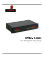
1
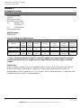
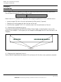
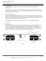
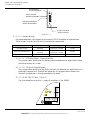
RMMV Series
Rack Mount AC/DC Power Supply
Operating and Installation Instructions
52-391 Rev A.02
RMMV Series Installation Instructions
7/13/2009, 10:26:56 AM
Warnings and Notices
WARNING - To reduce the risk of fire or electric shock, do not expose this product
to rain or moisture
WARNING - This installation and all servicing should be made by a qualified service
person and should conform to all local codes
NOTICE - This equipment shall be installed in a manner which prevents
unintentional operation from employees, janitors and cleaners working about the
premesis, by falling objects, by customers, by building vibration and by similar
causes
NOTICE - This equipment is not intended for use within the patient care areas of a
Health Care Facility
NOTICE - In order to comply with CSA Requirements, mount in rack only. Installer
sur support de montage seulement
Symbol Definitions
m
WARNING - Read the instruction manual to avoid personal injury or
property damage
c
WARNING - Risk of electric shock. Service to be performed by a qualified
service person
52-391 Rev A.02
Page 2 of 20
AlarmSaf 65A Industrial Way, Wilmington, MA 01887 978 658 6717 www.alarmsaf.com
RMMV Series Installation Instructions
7/13/2009, 10:26:56 AM
Table of Contents
Section
I. Warnings and Notices
Page
2
1 Introduction
4
2 Applicable Standards / Documents
5
3 System Overview
3.1 Electrical Ratings and Specifications
3.2 Terminal Descriptions
3.3 Fusing
6
6
7
8
4 Installation
4.1 Mounting
4.2 Wiring
9
9
10
5 Operating the RMMV Rack Mount Power Supply
5.1 Jumper Configuration
5.2 Visual Indicators
5.3 Troubleshooting
11
11
13
15
6 Specifications
6.1 Electrical Specifications
6.2 Temperature Specifications
6.3 Mechanical Specifications
17
17
17
17
Appendices:
Wiring and using an RMBE Series Battery Enclosure with the RMMV
Glossary
18
20
52-391 Rev A.02
Page 3 of 20
AlarmSaf 65A Industrial Way, Wilmington, MA 01887 978 658 6717 www.alarmsaf.com
RMMV Series Installation Instructions
7/13/2009, 10:26:56 AM
Section 1
Introduction
The RMMV series of rackmount power supplies provides either 24 or 28 VAC for powering CCTV or
similar low voltage AC operable equipment AND 12 and 24VDC for powering access control or
similar DC equipment.
The units are intended for mounting within a standard nineteen inch electronics rack and may not be
exposed to rain, moisture, or temperature conditions outside the stated range of operation.
All units:
Are single phase, cord connected, and operate on 120VAC @ 60 Hz.
Have separate internal AC and DC supplies, each with its own group of outputs
Have 8 DC outputs and 16 AC outputs
DC outputs are selectable for 12VDC or 24VDC by zone
AC outputs are selectable for 24VAC or 28VAC by zone to overcome long wire runs
Provide a green LED visual indicator for presence of output voltage by zone on the front panel.
Utilize a combination master ON/OFF switch and circuit breaker to control primary power.
Feature a plug-in cord with computer-style power entry module.
Feature screw-secured plug-in field wiring terminal strips.
Provide frontal access for changing fuses or zone output voltage configuration.
Utilize easily-obtainable ATM style 3A fuses unless PTC protected.
Provide enhanced surge and transient protection.
Are standard rack mount at 19" width and 3.5" (2RU) height, depth is 10".
52-391 Rev A.02
Page 4 of 20
AlarmSaf 65A Industrial Way, Wilmington, MA 01887 978 658 6717 www.alarmsaf.com
RMMV Series Installation Instructions
7/13/2009, 10:26:56 AM
Section 2
Applicable Standards / Documents
NFPA Standards
NFPA 72 National Fire Alarm Code
NFPA 70 National Electrical Code
US Standards
UL 294 Access Control System Units
UL 1076 Proprietary Burglar Alarm Units and Systems
UL 1481 Power Supplies for Fire Protective Signaling System
UL 2044 Commercal Closed-Circuit Television Equipment
Canadian Standards
ULC S318 Standard for Power Supplies for Burglar Alarm Systems
ULC S527 Standard for Control Units for Fire Alarm Systems
CAN/CSA-C22.2 No. 107.1-01 General Use Power Supplies
CAN/CSA C22.2 No. 1-98 Audio, Video, and Similar Equipment
Other
MEA Listed
California State Fire Marshal (CSFM) Listed
Applicable Local and State Building Codes
Requirements of the Local Authority Having Jurisdiction (LAHJ)
Note - Although the AC and DC sections of this product comply with the above certifications
separately, this preliminary unit as a whole has not yet been listed as a separate product with the
listing agencies.
FCC Compliance
This equipment has been tested and found to comply with the limits for Class A digital device pursuant to Part
15 of FCC rules. These limits are designed to provide reasonable protection against harmful interference
when this equipment is operated in a commercial environment. This equipment generates, uses, and can
radiate radio frequency energy and, if not installed and used in accordance with the instruction manual, may
cause harmful interference to radio communications. Operation of this equipment in a residential area is likely
to cause harmful interference, in which case, the user is required to correct the interference at his/her own
expense.
Listing Compliance Note
This product carries an ETL Listing from Intertek for one or more of the standards listed above. Intertek is
recognized by the Occupational Safety and Health Administration (OSHA) as a Nationally Recognized Testing
Laboratory (NRTL) and accredited by the Standards Council of Canada as a Testing Organization and Certifying
Body. The ETL Listed Mark is recognized by local inspectors and Authorities Having Jurisdiction (AHJs)
throughout North America. As Intertek is an NRTL recognized by OSHA, the ETL Listed Mark is an accepted
alternative to UL and, as such, inspectors and AHJs recognize, acknowledge, and accept the mark as proof of
product compliance. For more information about the NRTL program, we encourage you to visit the OSHA
Web site at www.osha.gov.
52-391 Rev A.02
Page 5 of 20
AlarmSaf 65A Industrial Way, Wilmington, MA 01887 978 658 6717 www.alarmsaf.com
RMMV Series Installation Instructions
7/13/2009, 10:26:56 AM
Section 3
System Overview
3.1 Electrical Ratings and Specifications
Manufactured By
AlarmSaf
65A Industrial Way
Wilmington, MA 01887
Tel:
800 987 1050
978 658 6717
Fax:
978 658 8638
www.alarmsaf.com
Model Numbers
RMMV Series
Electrical Ratings and Specifications
Fuse Protected Products
Model #
RMMV-122428-24F
RMMV-122428-24
Nominal
Input
Voltage
120
VAC
Max
Input
Current
4.2
Amp
120
VAC
4.2
Amp
AC Zones
DC Zones
16 x 24/28
8 x 12/24
VAC
VDC
PTC Protected Outputs
16 x 24/28
8 x 12/24
VAC
VDC
Max Total AC
Output
Current
12.5/10 Amp
AC
Max Total DC
Output
Current *
4A @ 24V
4A @ 12V
12.5/10 Amp
AC
4A @ 24V
4A @ 12V
Maximum
Current
per Zone
3 Amp
1.6 Amp
* - Note: Maximum total DC load of 12V and 24V supplies must not exceed 4A maximum.
Current drawn from the 12V supply must be subtracted from the 24V supply’s available
current.
Product Use
When installed in accordance with all standards listed in Section 2 of this document, the AlarmSaf
RMMV Power Supply line provides AC power for cameras and related accessories or other AC
powered devices and DC power for DC CCTV cameras, access control equipment, IT equipment and
related accessories, or other DC powered devices.
52-391 Rev A.02
Page 6 of 20
AlarmSaf 65A Industrial Way, Wilmington, MA 01887 978 658 6717 www.alarmsaf.com
RMMV Series Installation Instructions
7/13/2009, 10:26:56 AM
3.2 Terminal Descriptions
All terminal strips are removable with locking screws and accept wire sizes from 12-26AWG. Wire
should be sized appropriately for voltage drop and current carrying capability. All terminals are
labelled for polarity or phasing where appropriate.
AC FAULT
OUTPUT
BATTERY
CONNECT
COMMON
FAULT OUTPUT
AC Power Supply
DC Power Supply
Configure internal jumpers prior to use
See Instruction Manual 52-XXX
OUT24 OUT23 OUT22 OUT21
-
+ -
+ -
+
-
+
OUT20 OUT19 OUT18 OUT17
-
+ -
12V
BULK
OUTPUT
24V
BULK
OUTPUT
+
-
+ -
+
OFF
RESET
Configure internal jumpers prior to use
See Instruction Manual 52-XXX
ON
NO
NC
C
COMMON
FAULT
NO
NC
AC
FAULT
C
-
+
-
+ -
+
BAT
24V
DC
12V
DC
OUT5
OUT4
OUT3
AC POWER
OUT32 OUT31 OUT30 OUT29
-
+ -
+
-
+ -
+
OUT28 OUT27 OUT26 OUT25
-
+ -
+ -
+
-
OUT8
-
+
Remove load or reset main power to restore PTC protected zones
For fused units remove front panel to replace fuse.
On other than ‘F’ series units, OUT17 thru OUT32 are Class 2 Power Limited
Rear Panel
AC
DISTRIBUTED
OUTPUTS
+
OUT7
-
OUT6
+ -
+ -
+
-
+ -
OUT2
+ -
+
OUT1
-
+
Remove load or reset main power to restore PTC protected zones
For fused units remove front panel to replace fuse.
On other than ‘F’ series units, OUT1 thru OUT8 are Class 2 Power Limited
DC
DISTRIBUTED
OUTPUTS
Figure 3.2.1
3.2.1 AC Input
120 VAC Input: cord set - AlarmSaf Part# A095057
3.2.2 Distributed DC Outputs (Out1 - Out8)
Each distributed output is individually over-current protected (3A for fuse protected units,
1.6A for PTC protected units). Each output can be programmed for voltage by front panel
jumper selection.
3.2.3
Battery Terminals (BAT +/-)
Product uses 24V battery set to provide backup to both 12VDC and 24VDC outputs
Battery only provides backup to the DC portion of the supply
Terminals internally fused at 15 Amps
Battery presence detection available by setting internal jumpers
Minimum battery charging capacity: 7 Amphours
Maximum battery charging capacity: 80 Amphours within 48 hours
Contact AlarmSaf for spreadsheet-based battery software, PowerCAD 2.0
Note - It is the responsibility of the installer to determine the minimum battery requirement for the
particular application in which the supply is being used. Backup batteries should be serviced at
regular intervals as determined by local and/or national codes.
3.2.4 Bulk 24V Output Terminals (24VDC +/-)
Bulk 24V output of internal supply. Full current capacity of supply is available on this single
output terminal set.
3.2.5 Bulk 12V Output Terminals (12VDC +/-)
Bulk 12V output of internal supply. Full current capacity of supply is available on this single
output terminal set.
52-391 Rev A.02
Page 7 of 20
AlarmSaf 65A Industrial Way, Wilmington, MA 01887 978 658 6717 www.alarmsaf.com
RMMV Series Installation Instructions
7/13/2009, 10:26:56 AM
3.2.6
Fault Outputs (Common Fault / AC Fault)
Form C Contacts
Contacts rated at 1A @ 24VDC, 0.5A @ 120VAC
Fault relays employ “fail-safe” operation and are powered in a non-fault condition (connection
between common and NO when no fault exists)
Each internal supply has independent sets of fault contacts
3.2.7 Distributed AC Outputs
Each distributed output is individually over-current protected (3A for fuse protected units,
1.6A for PTC protected units).
3.3 Fusing
When replacing fuses in the RMMV, only the equivalent type and rating are to be used. The RMMV
utilizes commonly available Automotive Miniature fuses (Type ATM). Units whose model numbers
end in “F” employ ATM-3 fuses on the PCB located behind the front panel of the RMMV. An extra
fuse is provided on the bottom right corner of the PCB.
The internal PS5-M contains two replacable fuses - the Battery Fuse and the ABC Buss Fuse. Both
fuses are rated at 15A (ATM-15). The AC Input fuse is a soldered-in non-replacable fuse. If it is
determined that this fuse has opened, the PS5-M board must be returned to AlarmSaf for repair.
The internal SPS4 contains one replacable 7.5A (ATM-7.5) fuse.
52-391 Rev A.02
Page 8 of 20
AlarmSaf 65A Industrial Way, Wilmington, MA 01887 978 658 6717 www.alarmsaf.com
RMMV Series Installation Instructions
7/13/2009, 10:26:56 AM
Section 4
Installation
4.1 Mounting
4.1.1 Mount the unit in locations that meet the following temperature and humidity requirements.
Do not expose to conditions outside of these ranges.
Temperature
Humidity
0 °C to 49 °C (32 °F to 120 °F)
32 °C (90 °F) @ 93%
Mount the unit in a standard 19" equipment rack using the supplied 10-32 X ¾" machine scre ws.
Locate an open 2RU slot in the rack and remove the filler panel(s) (if present)
Slide the unit into the open slot from the front of the rack
Install the four supplied 10-32 X ¾" machine screws into the end brackets of the unit
4.1.2 Removing the faceplate of the unit
To remove the faceplate of the RMMV Rack Mount Power Supply, remove the four screws at the
corners of the faceplate. Pull out gently on the faceplate to disengage the LEDs from the holes in the
faceplate.
1
2
3
4
5
6
7
8
9
10
11
12
13
14
15
16
18
19
20
21
22
23
24
REMOVE FOUR
SCREWS
4.1.3 Replacing the faceplate of the unit
Gently slide the faceplate over the output LEDs and secure with the four screws previously removed..
52-391 Rev A.02
Page 9 of 20
AlarmSaf 65A Industrial Way, Wilmington, MA 01887 978 658 6717 www.alarmsaf.com
RMMV Series Installation Instructions
7/13/2009, 10:26:56 AM
4.2 Wiring
4.2.1 Wire Routing
All wiring must be installed in accordance with NFPA70 [NEC760] and all local code
requirements.
Power Limited wiring requires that power limited and nonpower limited wiring remain physically
separated. All power limited circuits must remain at least one quarter inch (¼") away from any
nonpower limited circuit wiring.
4.2.2 AC Power Connection
Before using the distributed power outputs, the unit must be connected to the main electrical
power. Use the supplied cord set to plug the unit into the rack power strip and verify that the AC
indicator light built into the main ON/OFF switch on the rear panel and the Green LED's on the
front panel are illuminated when the unit is turned on.
Shut off the electrical power to the location of the unit, and then complete the general
installation.
4.2.3 Field Wiring
Locate the field terminal wiring blocks on the back panel of the unit and remove the terminal
block from the header (there are two locking screws on either end of the terminal block).
Connect the wiring for the connected equipment to the terminal block. The back panel of the
enclosure is labeled with the function and polarity or phase indications ( See also section 3.2).
Replace the terminal block on the header and tighten the locking screws.
AC FAULT
OUTPUT
BATTERY
CONNECT
COMMON
FAULT OUTPUT
AC Power Supply
DC Power Supply
Configure internal jumpers prior to use
See Instruction Manual 52-XXX
OUT24 OUT23 OUT22 OUT21
-
+ -
+ -
+
-
+
OUT20 OUT19 OUT18 OUT17
-
+ -
12V
BULK
OUTPUT
24V
BULK
OUTPUT
+
-
+ -
+
OFF
RESET
Configure internal jumpers prior to use
See Instruction Manual 52-XXX
ON
NO
NC
C
COMMON
FAULT
NO
NC
AC
FAULT
C
-
+
-
+ -
+
BAT
24V
DC
12V
DC
OUT5
OUT4
OUT3
AC POWER
OUT32 OUT31 OUT30 OUT29
-
+ -
+
-
+ -
+
OUT28 OUT27 OUT26 OUT25
-
+ -
+ -
+
-
OUT8
-
+
Remove load or reset main power to restore PTC protected zones
For fused units remove front panel to replace fuse.
On other than ‘F’ series units, OUT17 thru OUT32 are Class 2 Power Limited
Rear Panel
AC
DISTRIBUTED
OUTPUTS
+
OUT7
-
OUT6
+ -
+ -
+
-
+ -
OUT2
+ -
+
OUT1
-
+
Remove load or reset main power to restore PTC protected zones
For fused units remove front panel to replace fuse.
On other than ‘F’ series units, OUT1 thru OUT8 are Class 2 Power Limited
DC
DISTRIBUTED
OUTPUTS
Figure 4.2.1
52-391 Rev A.02
Page 10 of 20
AlarmSaf 65A Industrial Way, Wilmington, MA 01887 978 658 6717 www.alarmsaf.com
RMMV Series Installation Instructions
7/13/2009, 10:26:56 AM
Section 5
Operating the RMMV Rack Mount Power Supply
5.1 Jumper Configuration
5.1.1 AC Zones
Each individual AC output zone may be configured for a 24VAC or 28VAC output. The output
setting is controlled by the movable jumper plugs behind the front panel (JP1-JP16). The upper
setting (V2) is for a 28VAC output, the lower setting (V1) is for a 24VAC output.
Output Voltage Setting
CAUTION:
JP1
J3
V2
FOR CONTINUED PROTECTION AGAINST RISK OF FIRE
REPLACE ONLY WITH SAME TYPE 3A. 32V FUSE.
DISCONNECT SUPPLY CORD BEFORE
CHANGING FUSE
JP2
JP3
JP4
JP5
JP6
JP7
UTILISER UN FUSIBLE DE RECHANGE
DE MEME TYPE 3 A 32 V
DE'BRANCHER AVANT DE REMPLACER LE FUSIBLE
ATTENTION:
JP8
JP9
JP10
JP11
JP12
JP13
JP14
JP15
V1
3A
32V
32V
JP16
V1
3A
F1
V2
3A
F2
32V
3A
F3
32V
3A
F4
32V
3A
F5
32V
3A
F6
32V
3A
3A
F7
32V
F8
32V
3A
3A
F9
32V
F10
32V
3A
F11
32V
3A
3A
F12
32V
F13
32V
3A
F14
32V
3A
F15
32V
F16
J6
J4
J7
F17
SPARE
J5
J1
REFER TO NAMEPLATE LABEL
FOR INSTALLATION DOCUMENT
REFERENCE NUMBER
J8
1
ZONES 1 - 8
1
J2
38-124 Rev B
ZONES 9 - 16
5.1.2 DC Zones
5.1.2.1 Internal Jumper and Switch Configuration
Before powering the system, the jumpers on the internal board(s) must be set for proper
operation. Do not change jumper or switch settings while the unit is powered or damage to
the system may occur.
5.1.2.1.1 PS5-M Jumper and Switch Settings
Each unit contains one PS5-M board. The switch and jumpers need to be configured for
desired operation.
5.1.2.1.1.1 DC Voltage Setting
Before installing an RMMV system, the output voltage setting switch of the PS5-M
board must be set. Do not change the switch setting while the unit is powered or
damage to the system may occur. In the RMMV, the switch should always be set away
from the green AC visual indicator for 24V (the PC board is labeled with the voltage
settings).
52-391 Rev A.02
Page 11 of 20
AlarmSaf 65A Industrial Way, Wilmington, MA 01887 978 658 6717 www.alarmsaf.com
RMMV Series Installation Instructions
7/13/2009, 10:26:56 AM
AC PRESENCE
VISUAL INDICATOR
BAT EARTH GND
DETECT DETECT
AC ON
EARTH GOUND
DETECTION ENABLE
VOLTAGE
SELECT
12V
BATTERY PRESENCE
DETECTION ENABLE
24V
OUTPUT VOLTAGE
SELECT SWITCH
Figure 5.2.1.1
5.1.2.1.1.2 Jumper Settings
For proper operation, the jumpers on the internal PS5-M should be set appropriately.
These jumpers may be set with the unit powered or unpowered.
Jumper
JP10 (Bat Detect)
JP9 (Earth Ground Detect))
JP5, JP6, JP7 (Buss 1 / Buss 2)
Description
Battery Presence Fault
Detection
Earth Ground Fault
Detection
ABC Buss Select
Settings
Jumper On - Enable
Jumper Off - Disable
Jumper On - Enable
Jumper Off - Disable
Buss 1
Default
Enable
Enable
Buss 1
5.1.2.1.1.2.1 JP10 (Bat Detect) - Battery Presence
This jumper allows disabling of the battery presence detection for applications where
no backup battery set is used.
5.1.2.1.1.2.2 JP9 (Earth Ground Detect)
This jumper allows disabling of the Earth Ground Fault detection for applications that
either don’t require Earth Ground Fault detection, or for applications where Earth
Ground Fault detection is already provided by the panel.
FLT
AC FLT
BUSS2
BUSS1
NO NC
C
GND
NO NC
COM
FLT
COM FLT
AC FLT
C
5.1.2.1.2.3 JP5, JP6, JP7 (Buss 1 / Buss 2)
The fuse should be set for Buss 1 under all conditions in the RMMV
ABC
Fig 5.1.1.2
52-391 Rev A.02
Page 12 of 20
AlarmSaf 65A Industrial Way, Wilmington, MA 01887 978 658 6717 www.alarmsaf.com
RMMV Series Installation Instructions
7/13/2009, 10:26:56 AM
5.1.2.1.2 SPS4 Jumper Settings
The SPS4 has two jumpers for setting its output voltage. It is factory set for 12VDC out. If
a different voltage is required, the jumpers must be changed as follows:
Voltage Output
5VDC
12VDC
5-18VDC Adjustable*
JP1
Left
Left
Right
JP2
Left
Right
Left
* - When using the adjustable range, adjust the output voltage using potentiomer R5
5.2 Visual Indicators
5.2.1 External Visual Indicators
5.2.1.1 Illuminated Power Switch / Circuit Breaker
The power switch will illuminate red when the power switch is in the “on” position and power
is present.
5.2.1.2 Front Panel Indicators
All units have front panel indicator LEDs. Each output has one LED which illuminates when
voltage is available at the corresponding output terminals.
CAUTION:
JP1
J3
V2
FOR CONTINUED PROTECTION AGAINST RISK OF FIRE
REPLACE ONLY WITH SAME TYPE 3A. 32V FUSE.
DISCONNECT SUPPLY CORD BEFORE
CHANGING FUSE
JP2
JP3
JP4
JP5
JP6
UTILISER UN FUSIBLE DE RECHANGE
DE MEME TYPE 3 A 32 V
ATTENTION:
JP7
JP8
JP9
JP10
DE'BRANCHER AVANT DE REMPLACER LE FUSIBLE
JP11
JP12
JP13
JP14
JP15
V1
3A
32V
32V
V2
JP16
V1
3A
F1
3A
F2
32V
3A
F3
32V
3A
F4
32V
3A
F5
32V
3A
F6
32V
3A
3A
F7
F8
32V
32V
3A
3A
F9
F10
32V
32V
3A
F11
32V
3A
3A
F12
32V
F13
32V
3A
F14
32V
F15
3A
32V
F16
J6
J4
J7
SPARE
D7
D8
D9
D10
D11
D12
D13
D14
D15
D16
F17
D6
D1
D2
J5
D3
D4
D5
J1
REFER TO NAMEPLATE LABEL
FOR INSTALLATION DOCUMENT
REFERENCE NUMBER
J8
1
1
J2
ZONES 1 - 8
38-124 Rev B
ZONES 9 - 16
Visual Indicators (D1-D16)
5.2.2 Internal Visual Indicators
5.2.2.1 Indicators on the internal PS5-M Board
The PS5-M contains five visual status indicators.
LED
AC ON (D19)
DC OUT (D15)
AC FLT (D22)
COM FLT (D16)
GND FLT (D23)
Description
AC Power
DC Output
AC Fault
Common Fault
Earth Ground Fault
Color
Green
Green
Yellow
Yellow
Yellow
Conditions
Lights when AC voltage is present on the input
Lights when DC voltage is present on the output
Lights when the AC input voltage is low or missing
See Section 5.2.2.1.4
Lights under an Earth Ground Fault condition
5.2.2.1.1 AC ON
For safety reasons, this LED illuminates any time there is AC voltage present at the AC
input, regardless of the AC fault status, battery state of charge, or power supply condition.
CAUTION - Always check for AC presence with a volt meter before servicing
5.2.2.1.2 DC OUT
This LED illuminates when DC voltage is available at the DC+/DC- terminals.
52-391 Rev A.02
Page 13 of 20
AlarmSaf 65A Industrial Way, Wilmington, MA 01887 978 658 6717 www.alarmsaf.com
RMMV Series Installation Instructions
7/13/2009, 10:26:56 AM
5.2.2.1.3 AC FLT
This LED illuminates when the AC input voltage falls below approximately 85% of the
nominal input voltage setting.
5.2.2.1.4 COM FLT
This LED illuminates on any of the following conditions:
High or Low Battery Voltage
High or Low Output Voltage
Missing / Damaged Battery
Earth Ground Fault
Fault received on ABC connector
5.2.2.1.5 GND FLT
This LED illuminates whenever there is an Earth Ground Fault between either positive or
negative rail of the power supply output.
5.2.2.2 Indicators on the SPS4 Board
The SPS4 contains three visual indicators
LED
DC IN (D7)
DC OUT (D8)
FLT (D6)
Description
DC Input
DC Output
Fault
Color
Green
Green
Yellow
Conditions
Lights when DC voltage is present on the input
Lights when DC voltage is present on the output
Lights when the SPS4 detects a fault condition
5.2.2.2.1 DC IN
This LED illuminates whenever there is DC voltage present on the input of the SPS4.
5.2.2.2.2 DC OUT
This LED illuminates when DC voltage is available at the outputs of the SPS4.
5.2.2.2.3 FLT
This LED illuminates if the DC output of the SPS4 goes either high or low or if the output
fuse (F1) ruptures.
52-391 Rev A.02
Page 14 of 20
AlarmSaf 65A Industrial Way, Wilmington, MA 01887 978 658 6717 www.alarmsaf.com
RMMV Series Installation Instructions
7/13/2009, 10:26:56 AM
5.3 Troubleshooting
WARNING - Installation and service should only be performed by a qualified service person and
should conform to all local codes
5.3.1 AC Section Troubleshooting
Condition
Possible Cause
Power cord unplugged
No power to Rack’s power strip
No green output LEDs lit and no
output voltages present
Power switch off
Tripped circuit breaker
Blown fuse (Fused models only)
One zone’s green output LED is not lit
and it’s output isn’t present
Tripped PTC (Power-Limited models
only)
Missing or damaged jumper
Output Zone LEDs vary in brightness
Normal
Solution
Verify both ends of the power cord
are plugged in
Verify power to Rack
Verify that the power switch on the
back panel is in the “On” position
The power switch also serves as a
circuit breaker. Switch to “Off/Reset”
for 30 seconds, verify output wiring
integrity, then switch back to “On”
Verify output wiring integrity, then
replace fuse (Power down unit while
changing fuse)
Verify output wiring integrity, then
pull voltage selection jumper for 30
seconds (note it’s position before
removing)
Verify that the zone’s jumper is
present and intact
This is a normal condition. 28V zones
will have a brighter output LED than
24V zones
5.3.2 DC Section Troubleshooting
Condition
Possible Cause
Power switch off
No output voltages present
Tripped input circuit breaker
Excessive total system loading
Internal problem
Blown output fuse or PTC
One output voltage not present
Excessive loading on output
Internal problem
Incorrect switch setting
The output voltage is incorrect
Excessive loading on output
Solution
Verify that the power switch on the
back panel is in the “On” position
The power switch also serves as a
circuit breaker. Switch to “Off/Reset”
for 30 seconds, verify output wiring
integrity, then switch back to “On”
Verify total system loading less than
the maximum
Contact AlarmSaf
Verify output wiring integrity and
loading, then replace fuse behind the
front panel. If the unit uses PTC
protection for the output, verify
output wiring integrity and loading,
remove the buss selection jumper for
the output for 30 seconds, then
replace the jumper.
See above
Contact AlarmSaf
Verify proper switch setting
Verify that individual and total output
current is less than rated current
52-391 Rev A.02
Page 15 of 20
AlarmSaf 65A Industrial Way, Wilmington, MA 01887 978 658 6717 www.alarmsaf.com
RMMV Series Installation Instructions
7/13/2009, 10:26:56 AM
AC trouble
Bad / Incorrect Battery Set
The internal PS5-M has shut down
Blown battery fuse on the internal
PS5-M
Excessive loading on output
The Common Fault relay is indicating
a fault condition
Improper ABC cable connection to
the internal PS5-M
Bad, Incorrect, or Missing Battery Set
Earth Ground Fault
Internal problem
The AC Fault relay is indicating a fault
condition
Low or Missing AC
Blown AC fuse on the internal PS5-M
Battery not connected
No battery presence detection
Bat Detect Jumper (JP10) set
incorrectly on the internal PS5-M
Internal problem
Verify presence of at least 102VAC on
the input, the AC switch is ON, and
the input circuit breaker is not tripped
Verify that a good battery set of the
proper voltage is connected to the
RMMV
If the PS5-M experiences an
overtemperature, overload, or output
voltage outside +/-10% regulation
fault ten times within 52 seconds, the
supply will shut down and transfer to
battery until AC power is cycled.
Verify fuse is intact - Check wiring
integrity before replacing fuse
Verify that output current is less than
the rated current
Verify proper connection of the ABC
cable(s)
Verify that a good battery set of the
proper voltage is connected properly
to the RMMV
An impedance exists in the system
between earth ground and the
output of the supply.
Contact AlarmSaf
Verify the presence of at least
102VAC on the input, the AC switch
is ON, and the input circuit breaker is
not tripped
This fuse is nonreplacable - Contact
AlarmSaf
Verify connection of an appropriate
battery set, and the integrity of the
wiring between the battery set and
the RMMV
Verify correct setting of Bat Detect
jumper
Contact AlarmSaf
52-391 Rev A.02
Page 16 of 20
AlarmSaf 65A Industrial Way, Wilmington, MA 01887 978 658 6717 www.alarmsaf.com
RMMV Series Installation Instructions
7/13/2009, 10:26:56 AM
Section 6
Specifications
6.1 Electrical Specifications
6.1.1 Input Voltage
6.1.2 Input Power
6.1.3 Input Frequency
6.1.4 Minimum Battery Charge Capacity
6.1.5 Maximum Battery Charge Capacity
6.1.6 Maximum Battery Charge Current
6.1.7 Maximum Battery Standby Current
6.1.8 DC Output Zones
6.1.9 AC Output Zones
6.1.10 Zone Output Current
6.1.11 Total DC Output Current
6.1.12 Total AC Output Current
120VAC nominal
504W Max
50-60Hz
7 Amphours
80 Amphours
2Amperes Maximum
80mA plus total output load
8 x 12/24VDC
16 x 24/28VAC
3A (Fused) or 1.6A (PTC)
8A / 4A @ 12VDC / 24VDC
12.5A / 10A @ 24VAC / 28VAC
6.2 Temperature Specifications
6.2.1 Ambient Temperature Range
6.2.2 Ambient Humidity
6.2.3 BTU Output
0ºC to 49ºC (32ºF to 120ºF)
93% at 32ºC (90ºF) maximum
TBD
6.3 Mechanical Specifications
6.3.1 Weight
6.3.2 Overall Size
18 lbs
19.00”W x 10.75”D x 3.50”H
Note: Depth includes terminal
strips on back panel and LEDs on
front panel
52-391 Rev A.02
Page 17 of 20
AlarmSaf 65A Industrial Way, Wilmington, MA 01887 978 658 6717 www.alarmsaf.com
RMMV Series Installation Instructions
7/13/2009, 10:26:56 AM
Wiring and using an RMBE Series Battery Enclosure with the RMMV
The RMBE Series of Battery Enclosures provides battery backup in a standard 19 inch 2RU rack
mountable enclosure. It can be configured for single or dual output. Each output can be configured
for either 12 or 24VDC. Configuration of the RMBE series is by pluggable jumpers on the back panel
of the enclosure. Each battery in the enclosure is protected by a 9 ampere PTC to provide protection
against overcurrent, short circuit, or incorrect configuration.
CAUTION - A lead acid battery can supply extremely large currents, presenting a risk of
personal injury or property damage if care is not taken when installing, configuring, or
servicing the RMBE.
CAUTION - A fully loaded RMBE can weigh more than 31 pounds, as installed. Care must be
taken when installing to prevent injury to the installer. Also, ensure that the rack that the
RMBE is being installed into can withstand the total weight of the equipment installed. The
RMBE should be installed near the bottom of the rack to ensure rack stability.
Battery Set 2 Configuration
Battery Set 1 Configuration
VOLTAGE SELECTION
IN-Parallel Set 1 and 2
OUT-Separates Set 1 and 2
24V
OR
The RMBE contains 2 battery sets which may be configured for:
12V / 12V - Two separate outputs; 24V / 24V Two separate outputs
12V and 24V - Two separate outputs
12V - One single output or 24V - One single output
VOLTAGE SELECTION
12V
+ - + BATTERY
CONNECT
24V
OR
12V
CAUTION - ONLY ONE VOLTAGE SELECTION PLUG + - + CAN BE INSTALLED TO EACH BAT SET
BATTERY
For complete information, read Installation
CONNECT
Instruction manual 52-342 or internal label.
Configuring the Rear Panel Jumpers on the RMBE
The rear panel jumpers configure the output of the RMBE unit. Each RMBE unit is shipped with 4-pin
configuration jumpers to be plugged into the appropriate socket(s) on the rear panel of the
enclosure. All jumpers are the same and may be used in any position.
CAUTION - Before connecting the RMBE to any other equipment, the rear panel
configuration jumpers must be set correctly or damage to the system may occur.
Each output has two jumper sockets to configure the voltage of its internal battery set. To configure
the voltage, a jumper must be placed into ONE of the two “Voltage Selection” sockets, as
appropriate.
Additionally, a socket is provided to parallel the two internal battery sets to create a single battery set.
To parallel the battery sets and create a single output, ensure both battery sets are set for the
same voltage, then insert a jumper into the socket labelled “Parallel Set 1 and 2”.
CAUTION - If using the “Parallel Set 1 and 2” jumper to parallel the two battery sets, ensure
that both voltage setting jumpers are set to the same selection BEFORE inserting the
paralleling jumper or damage to the system may occur. Additionally, if the voltage
selection jumpers need to be changed, ensure that the paralleling jumper is REMOVED first
or damage to the system may occur.
52-391 Rev A.02
Page 18 of 20
AlarmSaf 65A Industrial Way, Wilmington, MA 01887 978 658 6717 www.alarmsaf.com
RMMV Series Installation Instructions
7/13/2009, 10:26:56 AM
Power Supply 1
Power Supply 2
B
A B
OUT 16
A B
OUT 15
A B
OUT 14
A
B
OUT 13
A B
OUT 12
A B
OUT 11
A B
OUT 10
OFF
RESET
A
ON
OUT 9
BAT
COM FLT
AC FLT
NO NC C
NO NC C
24V DC
-
+
-
+-
+
-
12V DC
+-
+
To reduce the risk of fire, replace interior
fuses only with same type and rating
AC POWER
B
A B
OUT 8
A B
OUT 7
A B
OUT 6
A
B
OUT 5
A B
OUT 4
A B
OUT 3
A B
OUT 2
CAUTION
RISK OF ELECTRICAL SHOCK
DO NOT OPEN
A
OUT 1
-
+-
OUT 8
+OUT 7
OUT 6
OUT 5
+OUT 4
+
-
OUT 3
+
OUT 2
-
+
OUT 1
AlarmSaf www.alarmsaf.com
Battery Set 2 Configuration
Battery Set 1 Configuration
VOLTAGE SELECTION
IN-Parallel Set 1 and 2
OUT-Separates Set 1 and 2
24V
The RMBE contains 2 battery sets which may be configured for:
12V / 12V - Two separate outputs; 24V / 24V Two separate outputs
12V and 24V - Two separate outputs
12V - One single output or 24V - One single output
VOLTAGE SELECTION
12V
OR
24V
+ - + -
OR
12V
CAUTION - ONLY ONE VOLTAGE SELECTION PLUG + - + CAN BE INSTALLED TO EACH BAT SET
BATTERY
For complete information, read Installation
CONNECT
Instruction manual 52-342 or internal label.
BATTERY
CONNECT
Wiring the RMBE to an RMMV Rack Mount Power Supply
Wiring between the RMBE and RMMV must be sized appropriately for the maximum current. The
terminal strips on the RMBE will accept AWG 12-26. Each battery set has two parallel outputs - both
of which are marked for polarity. If the “Parallel Set 1 and 2” jumper is in place, all four outputs are
paralleled, and any one of them may be used for connection. If more amphour capacity is required
than available in a single RMBE, multiple RMBE enclosures may be paralleled together for increased
capacity.
CAUTION - If paralleling multiple RMBE enclosures, ensure that the voltage selection and
paralleling jumpers are set appropriately BEFORE wiring them together or damage to the
system could occur.
Configuration Options
The following amphour and voltage combinations are possible with an RMBE with the appropriate
jumper settings.
Voltage Batt Set 1
12V
12V
12V
24V
24V
24V
Voltage Batt Set 2
12V
12V
24V
12V
24V
24V
Parelleling
Jumper
Out
In
Out
Out
Out
In
Output 1
Output 2
14AH @ 12V
14AH @ 12V
28AH @ 12V (Single Output)
14AH @ 12V
7AH @ 24V
7AH @ 24V
14AH @ 12V
7AH @ 24V
7AH @ 24V
14AH @ 24V (Single Output)
52-391 Rev A.02
Page 19 of 20
AlarmSaf 65A Industrial Way, Wilmington, MA 01887 978 658 6717 www.alarmsaf.com
Glossary
7/13/2009, 10:26:56 AM
Glossary
ABC
See “Accessory Board Connector”
Accessory Board Connector
Connector present on some AlarmSaf power supplies and accessory boards, allowing plug-in
expansion of the system
Accessory Board
An AlarmSaf product for use with AlarmSaf power supplies containing an ABC connector.
These boards allow plug-in expansion of the functionality of the system. Examples of
accessory boards include, but are not limited to, voltage distribution (simple and controlled),
secondary DC-DC power supplies, and NAC Circuit expanders.
AC-DC Converter
A DC power supply whose voltage input is either direct from the AC line or though a
step-down AC transformer
Buss 1 (B1)
The primary DC voltage in a system. Typically the higher of the two voltages in dual voltage
systems
Buss 2 (B2)
The secondary DC voltage in a system. Only dual voltage systems use this voltage.
Class 2 Power Limited
A voltage output or wiring which conforms to NEC Article 725.
Controlled Distribution
Voltage distribution providing on/off control for the outputs. Control can be from FAI, an
access control panel, card reader, or other device. The MB8(F) and CMB8(F) accessory
boards, and the APD8(F) are examples of controlled distibution.
DC-DC Converter
A DC power supply whose voltage input comes from another DC source. DC-DC converters
allow multi-voltage system backup with a single battery set.
FAI
See “Fire Alarm Interface”
Fire Alarm Interface
Input present on some AlarmSaf products allowing control of output(s) in the system.
Typically used for dropping power to maglocks on egress doors during a fire alarm
condition, but can also be used for other control functions, such as resetting smoke
detectors
Power Limited
A voltage output or wiring which conforms to NEC Article 725.
PTC
A resettable overcurrent protection device, similar to a fuse or circuit breaker.
Rack Mount
A product which has an enclosure that allows mounting in a standard 19 inch equipment
rack
Simple Distribution
Voltage distribution without any control function for the distributed outputs. Power is
always available to the outputs. The PD8(F) accessory board is an example of simple
distribution.
Voltage Distribution
Splitting a bulk power supply output into multiple, current limited outputs to prevent a
single circuit failure from talking down an entire system. The multiple terminal outputs also
simplify wiring by providing a pair of terminals for each circuit, rather than wiring several
circuits to a single pair of terminals.
Glossary Rev A.01
Page 20 of 20
AlarmSaf 65A Industrial Way, Wilmington, MA 01887 978 658 6717 www.alarmsaf.com