1
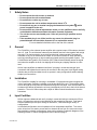
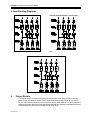
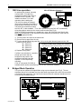
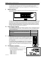
CX-A450 Amplifier
Installation & User Guide V3.0
Cloud Electronics Limited
140 Staniforth Road, Sheffield, S9 3HF England
Tel +44 (0) 114 244 7051
Fax +44 (0) 114 242 5462
E-Mail: [email protected]
Web site: http://www.cloud.co.uk
CX-A450: Installation and Operation Manual
1
CX-A450 Amplifier
Installation and operation manual
Contents
Section
Page
1
Safety Notes ....................................................................................................... 2
2
General ............................................................................................................... 2
3
Installation .......................................................................................................... 2
4
Input Facilities..................................................................................................... 2
5
Input Routing Diagrams ...................................................................................... 3
6
Output Details ..................................................................................................... 3
7
100V Line operation............................................................................................ 4
8
Bridged Mode Operation..................................................................................... 4
9
Status Indicators ................................................................................................. 5
10
Power Supply Capacity....................................................................................... 5
11
VCA Modules...................................................................................................... 5
12
VCA Module Installation ..................................................................................... 5
13
Remote Level Plate Connections........................................................................ 6
14
Speaker Equalisation Modules ........................................................................... 6
15
Equalisation Module Installation ......................................................................... 7
16
Field Servicing .................................................................................................... 7
17
General Specifications........................................................................................ 7
18
Technical Specifications ..................................................................................... 7
07-03-05 V3.0
CX-A450: Installation and Operation Manual
2
1
Safety Notes
•
•
•
•
•
Do not expose the unit to water or moisture
Do not expose the unit to naked flames.
Do not block or restrict any air vent
Do not operate the unit in ambient temperatures above 35oC
Do not touch any part or terminal carrying the hazardous live symbol ( ) while
power is supplied to the unit.
• Do not perform any internal adjustments unless you are qualified to do so and fully
understand the hazards associated with mains operated equipment.
• The unit has no user serviceable parts. Refer any servicing to qualified service
personnel.
• If the moulded plug is cut off the lead for any reason, the discarded plug is a
potential hazard and should be disposed of in a responsible manner.
For more detailed information refer to the rear of the manual.
2
General
The CX-A450 is a four-channel power amplifier with a typical output of 50 watts per channel
into a 4Ω load. The unit features extremely low distortion and low noise together with a high
slew rate. Full circuit protection is provided and the load is disconnected if the heat sink
overheats or any DC is detected at the output. A five-second switch-on delay operates to
avoid any switching thumps or other extraneous signals reaching the speaker system. The
CX-A450 also has Dynamic Clip Protection (DCP) that will automatically reduce the signal
level when the amplifier is driven into clipping thus limiting any clipping distortion to a low
level.
All four input amplifiers are balanced and have 3-pin plug in screw terminal type input
connectors with adjacent level controls, all mounted on the rear panel. Input signal routing
switches are provided and allow the unit to operate in many configurations whilst retaining
simple input connections.
3
Installation
The CX-A450 is suitable for mounting in a standard 19" equipment rack and occupies two
units of rack space. Sufficient ventilation must be provided for the unit. The amplifier draws
cool air through the front panel and exhausts through the rear panel, care must be taken not
to obstruct the airflow otherwise the unit may intermittently turn off due to the built-in thermal
protection. The unit is 320mm deep but a depth of 400mm should be allowed to clear the
connectors.
4
Input Facilities
All four inputs are balanced and use 3-pin plug-in screw terminal type connectors (3.5mm
pitch). All inputs have a level control adjacent to their respective connector. Rear panel
mounted switches provide input routing on channels 2, 3 and 4 allowing a variety of
configurations.
In its default configuration, the unit operates as four independent amplifiers. Two stereo
pairs, driven from one stereo source and four channels driven from one mono source are
also possible by suitably configuring the input routing switches. Schematic diagrams of the
switching network in various configurations can be found on page 3.
07-03-05 V3.0
CX-A450: Installation and Operation Manual
3
5 Input Routing Diagrams
4 independent mono amplifiers
Fig 1
4 mono outputs fed from 1 mono input
Fig 2
2 stereo amplifier pairs fed from 1 stereo input pair
Fig 3
6
Output Details
Four 2-pole plug-in screw terminal type connectors (5mm pitch) are provided on the rear
panel for the four speaker outputs; these can accommodate flexible leads up to 2.50mm².
Do not make any connections to the unit with the power cable attached. It is good practice to
distance the output wiring from the input wiring and keep the speaker wires twisted until they
are terminated to reduce any cross-talk to a minimum level.
07-03-05 V3.0
CX-A450: Installation and Operation Manual
4
CH4
0V
CH3
CH2
0V
MINIMUM LOAD 4OHMS
OUTPUT RATING 50W/4OHMS
0V
CXL-40T Wired to Channel 4
SPEAKER OUTPUTS
An optional four-channel, internally
mounted 40W, 70V/100V-line
transformer module (CXL-4160) is
available for the CX-A450. The
installer can select 70 or 100V
100V
operation when installing the
CXL-4160 by means of soldered
links on the underside of the PCB. A
0V
single channel externally wired 40W
CXL-40T
Fig
4
70V/100V-line transformer module;
the CXL-40T, is also available. 70 or 100V operation from the CXL-40T is selected by
wiring the speaker network to the correct screw terminal (See Fig 4).
When a 70/100V line transformer is installed to a zone, the 65Hz high pass filter for that
zone must be switched on, the instructions below detail the procedure you must follow to
activate the appropriate filter
0V
100V Line operation
CH1
7
R
Black
W
P
Blue
1) Turn the power off & remove the mains lead.
2) Remove the top panel from the unit.
3) Turn the relevant 65Hz high pass filter ‘on’ by moving the relevant jumpers to the ‘ON’
position (see list below).
J1 = Channel 1
Location of 65Hz Filter Jumper for Channel 2
(The other 65Hz jumpers are placed similarly around the PCB)
J2 = Channel 2
J3 = Channel 3
J4 = Channel 4
4) Replace the top panel.
If a filter is not switched on, operation
at high input levels and low
frequencies may result in the
transformer saturating and the
amplifier’s VI and clip limiting
operating.
A 2U 19" rack panel (CXL-800) is
available which can accommodate up to 8 CXL-40T transformer modules
8
Fig 5
Bridged Mode Operation
The unit can be operated in Bridged Mode using any two channels (see Fig 6). The two
amplifiers that are to be bridged must have the same signal input fed to each of them and be
out of phase with each other. The input level controls of the two channels should both to be
set to the fully clockwise position.
Wiring Channels 3 and 4 in Bridged Mode
Fig 6
07-03-05 V3.0
CX-A450: Installation and Operation Manual
5
The output load should then be connected between the two positive (HOT) outputs of the
relevant channels (no connection to 0V). You must ensure that the positive wire is
connected to the "first channel" output and the negative wire is connected to the "second
channel" output (see fig 6).
9
Status Indicators
The front panel of the CX-A450 has an array of LED’s that indicate the status of all four
channels (see Fig 7).
Fig 7
The lower green ‘signal’ LED illuminates when a signal is detected, the yellow 'peak' LED will
illuminate when the amplifier’s DCP is operating and the top red ‘protect’ LED indicates that
the protection relay has disconnected the load. Please note that it is normal for all four red
LED's to illuminate for approximately five seconds when the unit is switched on, indicating
operation of the switch-on delay circuitry. The green ‘power’ LED at the bottom right of the
front panel illuminates when the power is switched on.
10
Power Supply Capacity
The CX-A450 has 100mA of current available for optional modules. Exceeding this limit will
cause temporary power supply failure. Use the table below to verify your proposed system
does not exceed this limit.
Module Name
Current Required
BOSE® EQ cards: M8, M32, MA12, 402, 502A, 802, MB4, MB24,
502B, 502BEX
BOSE® EQ cards: LT3202, LT4402, LT9402, LT9702
BOSE® EQ card: M16
VCA-5
11
17mA
24mA
9mA
VCA Modules
A single channel VCA module ‘VCA-5’ is available as a plug-in option
for each of the four channels. When a VCA-5 is installed to a channel
it allows the channel level to be controlled remotely with the optional
RL-1 remote plate.
The circuitry uses the industry standard 'Thats 2150A' VCA providing
very low distortion and up to 90dB attenuation. The VCA module can
be wired to provide muting by using an auxiliary relay connected to a
fire alarm control panel. Contact our technical department for further
details.
12
12mA
VCA Module Installation
1. Turn the power off and remove the mains cable
2. Remove the top panel
3. Select the required PCB mounted VCA connector
and remove its jumper (see list below)
CON1 = Channel 1
CON2 = Channel 2
CON3 = Channel 3
CON4 = Channel 4
07-03-05 V3.0
Fig 9
Fig 8
CX-A450: Installation and Operation Manual
6
4. Unscrew the relevant blanking plate from the rear
of the unit & retain the screw.
5. Adjacent to the connector there is an M3 fixing
screw remove & retain this screw then fit a 35mm
M3 hex spacer (supplied) in its place.
6. Push the 10-way VCA plug onto the PCB connector, aligned so the cable enters it from
the rear of the chassis (See Fig 9) check there is contact with all 10 pins.
7. Position the VCA module’s 3-pin socket through the rear panel cut-out and secure using
M3 screws (both removed earlier)
8. Replace the top panel.
VCA Module Installed to Channel 1
Fig 10
13
Remote Level Plate Connections
The RL-1 is a remote control plate that allows the level of a specific channel to be remotely
controlled (in conjunction with the VCA-5). The RL-1 is compatible with UK domestic
electrical accessories and can be mounted onto a standard British flush or surface mounted
25mm deep back box (The RL-1A is available for the US market).
Remote Level Control Wiring
Fig 11
As Fig 10 shows, the RL-1 is connected to a CX-A450 remote connector with a two-core
cable that has an overall screen. It is possible to connect a single remote control module to
control more than one channel simultaneously (Fig 11). As more channels are linked the law
of the control will be compromised resulting in an uneven control of volume; this has proved
to be of little consequence operationally.
14
Speaker Equalisation Modules
Each channel of the CX-A450 can have a speaker equalisation module installed so that its
output will be compensated correctly for a wide range of speakers.
The following speaker models are supported:
- Bose® Speaker models: M8, M16, M32, MA12, 402, 502A, 502B, 502BEX, 802, MB4,
MB24, LT3202, LT4402, LT9402, LT9702
07-03-05 V3.0
CX-A450: Installation and Operation Manual
15
7
Equalisation Module Installation
1. Turn the power off and remove the mains lead.
2. Remove the top panel from the unit.
3. Select the required PCB connector (see list below) that
you wish to install the equalisation module to and
remove the bypass jumper adjacent to it.
4.
5.
6.
7.
Ch 1
CON 6
J5
Ch 2
CON 7
J6
Ch 3
CON 9
J7
Ch 4
CON 10
J8
Configure the relevant 65Hz filter to ‘ON’ (See section
7)
Fit the EQ card to the connector so that the module
board is perpendicular to the main board.
Push down on the EQ card until it locates with a click.
Replace the top panel.
NOTE #1: Before installing your optional modules, ensure
that the total power requirement does not exceed the limits
of the CX-A450 (see section 10).
NOTE #2: Each channel of the CX-A450 can have both
the VCA-5 module and Bose EQ card installed at the
same time.
16
Field Servicing
The CX-A450 is ruggedly built and uses proven reliable
circuitry. It requires no more than the occasional removal
of any dust that may have built up inside the unit because
of the forced cooling.
17
General Specifications
Inputs
Outputs
Protection
Status Indicators
Cooling
Dimensions
Weight
18
Fig 12
Balanced via 3-pin plug-in screw terminal type connectors
2-pin plug-in screw terminal type connectors for flexible cables up to 2.5mm²
VI limiting, DC offset, Thermal, Switch-on Delay & Dynamic Clipping Protection
LED indicators on each channel for Signal, Peak &Protect
Force cooled using variable speed DC fan
482.6mm x 88.0mm (2U) x 300.0mm deep (+ connectors)
7.15kgs
Technical Specifications
Rated Output 4 Ohm load(s)
Rated Output 8 Ohm load(s)
Bridged Output
100V Output
70V Output
Frequency Response
THD+N
07-03-05 V3.0
50W nominal
35W nominal
100W nominal into 8 Ohm load, minimum load 8 Ohms
40W into 250 Ohms
40W into 125 Ohms
+0dB –0.5dB 10Hz to 20kHz, switch-able high pass filter –3dB @65Hz
0.02%, typical, @1kHz, 60W into 4 Ohms, one channel driven,
measurement BW 22Hz to 80kHz
CX-A450: Installation and Operation Manual
8
VCA Module THD+N
Crosstalk
Typical, between adjacent
channels
<0.03% 1kHz, measurement BW 22Hz to 80kHz
Input Sensitivity
Input Impedance
Noise
0dBu (775mV)
10k balanced / 5k unbalanced
<96dB rms below rated output, un-weighted, measurement BW
22Hz to 22kHz
230V ±5% (115V ±5% available)
230V – T3.15A H
115V – T6.3A H
20mm x 5mm High Breaking Capacity 250V
Power Input
Fuse rating
Fuse type
Typically -70dB @10kHz with 4 Ohm load
This product conforms to the following European EMC Standards:
BS EN 55103-1:1997
BS EN 55103-2:1997
This product has been tested for use in commercial and light industrial environments. If the equipment
is used in controlled EMC environments, the urban outdoors, heavy industrial environments or close to
railways, transmitters, overhead power lines etc. the performance of the unit may be degraded.
The product conforms to the following European electrical safety standard.
BS EN 60065:1998
07-03-05 V3.0
CX-A450: Installation and Operation Manual
9
Safety Considerations and Information
The unit must be earthed. Ensure that the mains power supply provides an effective earth
connection using a three wire termination.
When the mains switch is in the off ‘O’ position the live and neutral conductors of the mains
transformer are disconnected, however some parts of the product will still remain connected to
the live and neutral mains conductors
CAUTION – Installation
Do not expose the unit to water or moisture
Do not expose the unit to naked flames.
Do not block or restrict any air vent
Do not place liquid filled containers on or around the unit
Do not operate the unit in ambient temperatures above 35oC
CAUTION – Hazardous Live
Do not touch any part or terminal carrying the hazardous live symbol ( ) while power is
supplied to the unit.
Terminals to which the hazardous live symbol refers require installation by a qualified person.
CAUTION - Mains Fuse
Replace the mains fuse only with the same type and rating as marked on the rear panel. The
fuse body size is 20mm x 5mm.
CAUTION – Servicing
The unit contains no user serviceable parts. Refer servicing to qualified service personnel. Do
not perform servicing unless you are qualified to do so.
Disconnect the power cable from the unit before removing the top panel and do not make any
internal adjustments with the unit switched on.
Only reassemble the unit using bolts/screws identical to the original parts
In the interest of continuing improvements Cloud Electronics Limited reserves the right to alter
specifications without prior notice.
Bose
is a Registered Trademark of The Bose Corporation.
Cloud Electronics Limited 140 Staniforth Road Sheffield S9 3HF England
Telephone +44 (0) 114 244 7051 Fax +44 (0) 114 242 5462 E-mail: [email protected]
07-03-05 V3.0