1
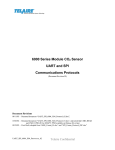
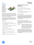
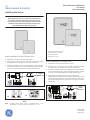
GE Measurement & Control Telaire Ventostat™ 8000 Series CO2 Sensor User Instructions Installing the Sensor !WARNING! Before performing service or maintenance operations on the systems, turn OFF main power switches to the unit. Electric shock can cause personal injury. Please read and follow the wiring instructions precisely; miswiring may cause permanent damage to the product. GE Measurement & Control 6860 Cortona Dr., Suite B Goleta, CA 93117 www.ge-mcs.com Basic Installation for Non-Display Units 1. Separate the case into its front and rear sections. 2. Secure the rear section of the case to the wall or junction box using the supplied screws, and make necessary wire connections. 3. Mount the Controller on the base by aligning the top clips and then securing to the bottom clips. Secure the Ventostat with the supplied set screw. A one-minute stabilization warmup will take place. Output Jumper Selections Basic Installation for Display Units 1. Separate the case into its front and rear sections. 2. Secure the rear section of the case to the wall or junction box using the supplied screws, and make necessary wire connections. 3. Mount the Controller on the base by aligning the top clips and then securing to the bottom clips. Secure the Ventostat with the supplied set screw. A one-minute stabilization warmup will take place. 4. When fitting the T8300 (pitot tube version), complete the installation by screwing the tube connectors to the input ports on the sensor. The tubing connectors can be attached to either input port. It will not affect the performance of the sensor. (See page 3 for further instructions.) Internal Label for Non-Display Units (b) 0-10V 0-5 V Jumper Settings for Non-Display (a) and Display (b) Units Output Jumper Selections (a) Note: Internal Label for Display Units Example b shows outputs of CO2 — 4-20 mA and CO2 — 0-10 V, humidity— 4-20 mA, and active temperature — 0-5 V. T63216-007 May 2013 Page 1 of 4 Ventostat Wiring Diagrams The Ventostat family of products has two basic configurations. One configuration provides three active outputs (CO2, RH and temperature) and an independent thermistor. It has an output terminal block with pins #1, 2 and 3. The other configuration provides only CO2 outputs and an independent thermistor and has no terminal block with pins 1, 2, and 3 installed. For electrical wiring and power supply requirements, these two configurations are identical; please follow the specific instructions for wiring. The recommended wire gauge is 18-22 AWG (1.0 to 0.75 metric). !WARNING! Ventostat products have three terminal pins that are connected inside the sensor to a common/ground: pin #2, 5 and 7 on the I/O terminal blocks and pin #2 on the power block. Do NOT connect positive (hot) 24 VAC power line to terminal number 2 of the terminal block. Figure 2: Display Unit Wiring for 4-Wire System, AC Power Caution! The T8100 Ventostats are either 3-wire or 4-wire type configurations, powered by either AC or DC voltage. They are not 2-wire or loop-powered devices. Wiring the units as 2-wire or loop-powered devices will irreparably damage the sensors and void the warranty. Note: For temperature measurements, Ventostat models contain a passive thermistor (terminal pins #4 and 5), which is electrically isolated from the other circuitry and should be wired independently from active CO2/RH/temperature outputs. The thermistor has no connection to the Ventostat common ground and/or power. The active temperature output has the same common (ground) as CO2 and RH outputs. Figure 3: Non-Display Unit Wiring for 3-Wire System, AC Power Figure 4: Non-Display Unit Wiring for 4-Wire System, AC Power Figure 1: Display Unit Wiring for 3-Wire System, AC Power Figure 5: Wiring CO2 Sensor Voltage Output to Honeywell M7415 Damper Actuator with W7459 Logic Module Page 2 Telaire Ventostat™ 8000 Series Sensing Duct CO2 Concentrations Accessory Enclosures Duct-Mounting the Enclosures Model T1508 Duct Mount Enclosure (Aspiration Box) Ventostat products can be installed inside the return air ductwork, if needed. As an alternative, please consider the T8031 unit. When mounting these products inside the ductwork, seal the hole around the wires and leave the duct insulation in place to prevent condensation which may damage the sensor. The T8100/T8200/T8300 units can be installed inside a Model 1508 Duct Mount Enclosure. Pitot Tube Installation for T8300 and T8300-D Install the mounting bracket, then install the pitot tube assembly as follows: Note: The length of the Tygon® tubing is 6 ft. (1.8 m) with the optional T62892 pitot kit for the T8300. In order to maintain optimum accuracy, the tubing should not be lengthened. If the sensor is mounted closer than 3 ft. (0.9 m) the excess tubing should be shortened to avoid interference with mechanical or moving devices. Model T1552 Outside Air Measurement Enclosure This NEMA-3R weatherproof enclosure includes thermostat and allows installing the sensor in environments with temperatures down to -40°F. Model T1505 Harsh Environment Enclosure For extreme environments where the sensor might be subjected to condensation or water spray such as those found in greenhouses or breweries- NEMA-3R rated. Ventostat Specifications 1. To mount the pitot tube, drill one 7/8” hole through the duct. 2. Insert the pitot tube and mark the two remaining holes for the mounting screws. 3. Punch or drill the two marked holes. Sensing Method Non-dispersive infrared (NDIR) absorption Gold-plated optics Patented ABC Logic self calibration algorithm 4. Note the direction of airflow in the duct. 5. Note the marking on the pitot tube flange and insert so that it is properly aligned with the airflow. CO2 Measurement Range 6. To ensure an air tight seal, make sure the mounting surface of the duct is clear of dirt or obstructions. Then, attach the pitot tube to the duct with sheet metal screws or rivets. T8100/T8200/T8300 0 to 2000 ppm (0 ppm = 0 V, 4 mA; 2000 ppm = 10/5V, 20 mA) 7. Check the length of the tubing before attaching to the sensor. The tubing should connect without stretching or pulling. If the length is long enough to create a loop or bind in the tubing, it should be shortened. 8. To shorten the tubing, remove the connectors that attach to the sensor and cut the tubing to length. 9. Replace the tubing connectors by using a twisting or screwing motion. Verify the connection is secure. Note: If the tubing length has been shortened, be sure the in-line filter is replaced on the pitot tube connector marked with an “H”. T8100/T8200/T8300 - 5P models 0 to 5000 ppm (0 ppm = 0 V, 4 mA; 5000 ppm = 10/5V, 20 mA) CO2 Accuracy ±30 ppm or 3% of reading, whichever is higher* Power Supply Requirements 18-30 VAC RMS, 50/60 Hz, or 18 to 42 VDC, polarity protected *CO2 accuracy statement excludes standard gas used for calibration that has an accuracy of 2%. In addition, there is a potential digital to analog error of up to 1%. Telaire Ventostat™ 8000 Series Page 3 RH Sensing Element Capacitive polymer sensor Power Consumption Typical 0.7 W at nominal voltage of 24V AC RMS RH Range 0% to 99% RH (non-condensing) Temperature Dependence 0.2% FS per °C (±0.11% per °F) Stability T8100/T8300 - Single Channel <2% of FS over life of sensor (15 years) RH Accuracy (25°C) ±2.5% RH (20 to 80% RH) ±3.5% RH (<20% and >80% RH) Active Temperature Accuracy T8200 - Dual Channel <5% of FS or <10% reading annual over life of sensor (10 years) ±0.8°C @ 22°C Pressure Dependence 0 to 50°C 0.135% of reading per mm Hg Certifications CE and RoHS compliant Signal Update Every 5 seconds CO2 Warm-up Time < 2 minutes (operational) 10 minutes (maximum accuracy) Operating Conditions 32°F to 122°F (0°C to 50°C) 0 to 95% RH, non-condensing Storage Conditions -40°F to 158°F (-40°C to 70°C) Flammability Classification UL94 5VA Thermistor Type NTC 10 Kthermistor Active Temperature Range ABC Logic™ Self Calibration System ABC Logic™ (Automatic Background Calibration) self calibration allows the sensor to continually recalibrate itself when the indoor concentrations drop to outside levels while the building is unoccupied. Generally a building must be regularly unoccupied for 4 hours or more for this self-calibration system to operate properly. Under these conditions, ABC Logic™ should maintain sensor calibration over the lifetime of the sensor. The ABC Logic™ should be turned OFF where a building is continuously occupied 24 hours per day, or where there could be significant sources of non-occupant related CO2 such as greenhouses, breweries and other industrial and food processing applications. Output Analog 0 to 5 V, (100 output impedance) 0 to 10 V (100 output impedance) and 4 to 20mA (RL maximum 500 ) available simultaneously for CO2 output Digital to analog error ±1% Warranty/Other Warranty 18 months parts and labor This product is covered by one or more of the following patents: 5,650,624 / 5,721,430 / 5,444,249 / 5,747,808 / 5,834,777 / 5,163,332 / 5,340,986 / 5,502,308 / 6,344,798 / 6,023,069 / 5,370,114 / 5,601,079 / 5,691,704 / 5,767,776 / 5,966,077 / 6,107,925 / 5,798,700 / 5,945,924 / 5,592,147 / 6,255,653 / 6,250,133 / 6,285,290 Thermistor Accuracy ±1°C (15° to 35°C) Warranty Repairs GE Sensing will repair Telaire product that fails to meet the terms provided for in the Return and Warranty Policy Statement (See, http:// www.ge-mcs.com/en/services-and-support.html).Warranty period shall start from date of manufacture and be based on product category and Page 4 Telaire Ventostat™ 8000 Series type of equipment as specified in Table 1: Product Warranty Periods. For all warranty repairs, GE Sensing will bear all product repair parts, labor, and standard ground shipping charges. Telaire Ventostat™ 8000 Series Page 5