1
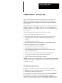
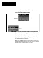
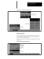
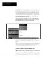
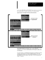
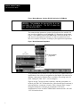
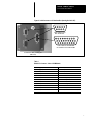
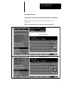
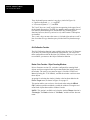
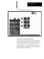
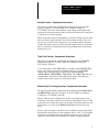
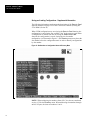
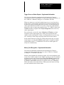
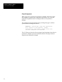
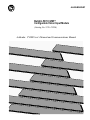
ALLEN-BRADLEY Bulletin 5370 CVIM Configurable Vision Input Module (Catalog No. 5370–CVIM) Addenda: CVIM User’s Manual and Communications Manual Disclaimer Important User Information Solid state equipment has operational characteristics differing from those of electromechanical equipment. “Application Considerations for Solid State Controls” (Publication SGI-1.1) describes some important differences between solid state equipment and hard–wired electromechanical devices. Because of this difference, and also because of the wide variety of uses for solid state equipment, all persons responsible for applying this equipment must satisfy themselves that each intended application of this equipment is acceptable. In no event will the Allen-Bradley Company be responsible or liable for indirect or consequential damages resulting from the use or application of this equipment. The examples and diagrams in this manual are included solely for illustrative purposes. Because of the many variables and requirements associated with any particular installation, the Allen-Bradley Company cannot assume responsibility or liability for actual use based on the examples and diagrams. No patent liability is assumed by Allen-Bradley Company with respect to use of information, circuits, equipment, or software described in this manual. Reproduction of the contents of this manual, in whole or in part, without written permission of the Allen-Bradley Company is prohibited. 1994 Allen-Bradley Company, Inc. Addenda: CVIM User’s Manual C and Communications Manual CVIM Firmware: Revision C05 The revised CVIM firmware adds capabilities to the CVIM system and changes the operation of some of its existing functions. This addendum describes these additions and changes and shows how they affect the user interface menus. This addendum also clarifies the descriptions of some functions in the User’s Manual (Catalog No. 5370–ND001, Series B), and the Communication Manual (Catalog No. 5370–ND002, Series C). See also the CVIM Firmware Release Notes. The following list briefly indicates the effect of the revisions: • A two–pulse frame reset camera can be used. • The standby status can be set On or Off when using an RS–232 host. • The procedure for entering the standby mode (during powerup) is changed. • • • • • • Multiple hosts can be selected. A second serial I/O port is available (Series B CVIM module only).* Internal configuration “saves” are confirmed. The “keyboard” layout has been modified. The grid calibration function is no longer available. The “calculator pad” operates in the octal mode when used to enter remote I/O rack addresses. • The border color can be selected for an object counting window. • Two frame reset cameras can be triggered independently. • The CFG Host default configuration is changed. *NOTE: On the Series B CVIM module, the pin assignments on the Module I/O connector have been changed. Refer to Second RS–232 Serial Port in this addendum for details. Two–Pulse Frame Reset Camera In order to accommodate two–pulse frame reset cameras, the Camera Type/Mode popup menu has been modified as shown in Figure 1 on page 2. It now has two frame reset menu boxes. If you are using a two–pulse frame reset camera, pick the Frame Reset 2 Pulse menu box to enable the two–pulse feature. If you are using a one–pulse frame reset camera, pick the Frame Reset 1 Pulse menu box. When you pick either of these menu boxes, the Shutter (usec): menu box 1 Addenda: CVIM User’s Manual and Communications Manual becomes active. When you then pick the Shutter (usec): menu box, the calculator pad appears as shown in Figure 2 on page 3. Figure 1 Changes to Camera Type/Mode Popup Menu Camera Type/Mode popup menu Frame Reset menu boxes: Camera popup menu Use the calculator pad to enter the appropriate shutter speed in microseconds. For the one–pulse frame reset camera, enter any value from 399 to 16,667. (Note: 0 is also a valid value. It must be used for one–pulse cameras that do not have electronic shutters.) For the two–pulse camera, enter any value from 200 to 8,000. For both cameras, the actual exposure time will be within 63uSec of the entered value. (Refer to the specifications in your camera’s user manual for shutter speed range data.) NOTE: The Allen–Bradley frame reset camera requires two pulses. If you are using a different frame reset camera, refer to the camera’s user manual to determine whether it is a one–pulse or two–pulse camera. 2 Addenda: CVIM User’s Manual C and Communications Manual Figure 2 Calculator Pad For Selecting Shutter Speed Camera Type/Mode popup menu Calculator pad Camera popup menu Multiple Host Selection The term “multiple host selection” means that you can select one host to perform CVIM/host configuration transfers, and select another host to perform all other CVIM/host operations. Figure 3 shows the Host Selection menu box modifications in the System popup menu. Figure 3 Modified Host Selection Menu Boxes Host Selection menu boxes System popup menu Env. popup menu 3 Addenda: CVIM User’s Manual and Communications Manual The CFG Host: menu box enables you to select a host for transferring CVIM configurations only. The SYS Host: menu box enables you to select a host for all other data communications, such as sending trigger pulses from the host and reading results block data from the CVIM system. (However, any CVIM communications port can be used for reading results block data, regardless of whether the device connected to the port is selected as a host.) Note that Stand Alone appears in the CFG Host: and SYS Host: menu boxes – this is the default “host” selection. When you pick either the CFG Host: menu box or the SYS Host: menu box, a Host Select popup menu appears as shown in Figure 4 (a separate Host Select popup menu is provided with each menu box). Figure 4 Host Select Popup Menu System popup menu Env. popup menu An example of using multiple hosts is to select RS–232 A as the configuration host (CFG Host:) and Remote I/O as the system host (SYS Host:). NOTE: You can select the same “host” (Stand Alone, Pyramid, Remote I/O, RS–232 A or B) as both the configuration host and the system host. Thus, you could select Pyramid for both CFG Host: and SYS Host:. Second RS–232 Serial Port (Series B CVIM Module Only) NOTE: Using the two RS–232 ports requires both a Series B CVIM module and a 2801–N27 I/O Interface Box. When you select either the CFG Host: or the SYS Host: menu box, a Host Select popup menu appears as shown in Figure 4, above (and in Figure 5 on page 5). Note that the Host Select popup menu contains two RS–232 menu 4 Addenda: CVIM User’s Manual C and Communications Manual boxes, labeled RS–232 A and RS–232 B. These menu boxes correspond to the two physical RS–232 ports on the 2801–N27 I/O Interface Box. Figure 5 Example: Selecting RS–232 Ports for CFG and SYS Hosts RS–232 port A selected for connection to the configuration host. RS–232 port B selected for connection to the system host. An example of using the two RS–232 ports is to select RS–232 A for CFG Host: and RS–232 B for SYS Host:. This is shown in Figure 5. (Alternatively, you could select RS–232 B for CFG Host: and RS–232 A for SYS Host:.) If you have a Series A CVIM module and attempt to select RS–232 port B, a “warning” message appears as shown in Figure 6 on page 6. The same message appears whenever you select the RS–232 B menu box in either the Host Select popup menu (Figure 4 and Figure 5) or the I/O popup menu (Figure 7 on page 6). 5 Addenda: CVIM User’s Manual and Communications Manual Figure 6 Warning Message: Selecting RS–232 B with Series A CVIM Module The communication parameters (protocol and baud rates) for each RS–232 port are selected from the corresponding RS–232 Parameters popup menus. Figure 7 shows ASCII protocol and 19200 baud selected for the RS–232 A port. You can select identical parameters (or different parameters) for the RS–232 A and RS–232 B ports, according to your application requirements. Figure 7 RS–232 Parameters Popup Menu I/O popup menu RS–232 Parameters popup menu Env. popup menu To accommodate the second RS–232 port, the Series B CVIM module has a modification to four of the pin assignments on the Module I/O connector. In addition, a dual–port I/O Interface Box is available. (The wiring in the I/O cable, Catalog No. 2801–NC17, was not changed.) Figure 8 on page 7 shows the cable connectors, and their pin numbers, on the dual–port 2801–N27 I/O Interface Box. (Note that the Port B connector is male and the Port A connector is female.) Table 1 through Table 8 (pages 7 through 9) indicate the connector pin assignments with various combinations of Series A and B CVIM modules connected to the –N21 and –N27 I/O interface boxes. 6 Addenda: CVIM User’s Manual C and Communications Manual Figure 8 Cable Connectors on I/O Interface Box (Catalog No. 2801–N27) 5 4 3 9 1 2 8 7 6 Cable connectors to RS–232 devices. 9 8 7 17 18 26 6 16 25 5 15 24 4 14 23 3 13 22 1 2 12 21 11 20 10 19 Cable connector from Module I/O connector on CVIM module. I/O Interface Box (Catalog No. 2801–N27) Table 1 Module I/O Connector: Series A CVIM Module Pin 1: Trigger input line #1. Pin 14: Output line #12. Pin 2: Trigger input line #2. Pin 15: Output line #13. Pin 3: Output line #1. Pin 16: Output line #14. Pin 4: Output line #2. Pin 17: Reserved. Pin 5: Output line #3. Pin 18: Reserved. Pin 6: Output line #4. Pin 19: Ground (power). Pin 7: Output line #5. Pin 20: Ground (power). Pin 8: Output line #6. Pin 21: Ground (chassis). Pin 9: Output line #7. Pin 22: Ground (signal). Pin 10: Output line #8. Pin 23: TXD (Transmit Data – RS–232 A). Pin 11: Output line #9. Pin 24: RTS (Request to Send – RS–232 A). Pin 12: Output line #10. Pin 25: RXD (Receive Data – RS–232 A). Pin 13: Output line #11. Pin 26: CTS (Clear to Send – RS–232 A). 7 Addenda: CVIM User’s Manual and Communications Manual Table 2 Module I/O Connector: Series B CVIM Module Pin 1: Trigger input line #1. Pin 14: Output line #12. Pin 2: Trigger input line #2. Pin 15: Output line #13. Pin 3: Output line #1. Pin 16: Output line #14. Pin 4: Output line #2. Pin 17: Reserved. Pin 5: Output line #3. Pin 18: Reserved. Pin 6: Output line #4. Pin 19: Ground (power). Pin 7: Output line #5. Pin 20: Ground (power). Pin 8: Output line #6. Pin 21: Ground (chassis). Pin 9: Output line #7. Pin 22: Ground (signal). Pin 10: Output line #8. Pin 23: TXD (Transmit Data – RS–232 A). Pin 11: Output line #9. Pin 24: TXD (Transmit Data – RS–232 B). Pin 12: Output line #10. Pin 25: RXD (Receive Data – RS–232 A). Pin 13: Output line #11. Pin 26: RXD (Receive Data – RS–232 B). Table 3 I/O Interface Box (Cat. No. 2801–N21): RS–232 Connector with Series A CVIM Pin 1: No connection. Pin 6: No connection. Pin 2: RXD (Receive Data – RS–232 A). Pin 7: RTS (Request to Send – RS–232 A). Pin 3: TXD (Transmit Data – RS–232 A). Pin 8: CTS (Clear to Send – RS–232 A). Pin 4: Ground (chassis). Pin 9: No connection. Pin 5: Ground (signal). Table 4 I/O Interface Box (Cat. No. 2801–N21): RS–232 Connector with Series B CVIM Pin 1: No connection. Pin 6: No connection. Pin 2: RXD (Receive Data – RS–232 A). Pin 7: TXD (Transmit Data – RS–232 B). Pin 3: TXD (Transmit Data – RS–232 A). Pin 8: RXD (Receive Data – RS–232 B). Pin 4: Ground (chassis). Pin 9: No connection. Pin 5: Ground (signal). Table 5 I/O Interface Box (Cat. No. 2801–N27): RS–232 Port A Connector with Series A CVIM Pin 1: No connection. Pin 6: No connection. Pin 2: RXD (Receive Data – RS–232 A). Pin 7: +5VDC Pin 3: TXD (Transmit Data – RS–232 A). Pin 8: No connection. Pin 4: +5VDC. Pin 9: No connection. Pin 5: Ground (signal). 8 Addenda: CVIM User’s Manual C and Communications Manual Table 6 I/O Interface Box (Cat. No. 2801–N27): RS–232 Port B Connector with Series A CVIM Pin 1: No connection. Pin 6: No connection. Pin 2: CTS (Clear to Send – RS–232 A). Pin 7: +10VDC Pin 3: RTS (Request to Send – RS–232 A). Pin 8: No connection. Pin 4: +10VDC. Pin 9: No connection. Pin 5: Ground (signal). Table 7 I/O Interface Box (Cat. No. 2801–N27): RS–232 Port A Connector with Series B CVIM Pin 1: No connection. Pin 6: No connection. Pin 2: RXD (Receive Data – RS–232 A). Pin 7: +5VDC Pin 3: TXD (Transmit Data – RS–232 A). Pin 8: No connection. Pin 4: +5VDC. Pin 9: No connection. Pin 5: Ground (signal). Table 8 I/O Interface Box (Cat. No. 2801–N27): RS–232 Port B Connector with Series B CVIM Pin 1: No connection. Pin 6: No connection. Pin 2: RXD (Receive Data – RS–232 B). Pin 7: +10VDC Pin 3: TXD (Transmit Data – RS–232 B). Pin 8: No connection. Pin 4: +10VDC. Pin 9: No connection Pin 5: Ground (signal). Standby On/Off Selection for RS–232 System Host When you select Pyramid, Remote I/O, RS–232 A, or RS–232 B as the system host (using the SYS Host: menu box), the CVIM system normally enters the standby mode after powerup and waits for a valid command from the host. If you select Pyramid or Remote I/O as the system host, the host performs an automatic polling function. From either of these hosts, the CVIM system always receives a valid command shortly after powerup and thereupon changes from the standby mode to the run mode. When you select RS–232 A or RS–232 B as the system host, however, the CVIM system might not receive a valid command after powerup, since the RS–232 host might not be programmed to perform an automatic polling function, or it might not be connected at the time that the CVIM system is powered up. In either case, the CVIM system would remain in the standby mode after powerup, and would thus be unable to perform run mode operations. 9 Addenda: CVIM User’s Manual and Communications Manual In order to enable the CVIM system for run mode operations when it is configured for RS–232 system host operations and does not receive a command from the RS–232 host, you can disable (turn “Off”) the standby mode using the RS–232 Standby: menu box. This menu box provides you with the choice of having the CVIM system enter the standby mode after powerup and wait for a command from the RS–232 host (On), or having the CVIM system bypass the standby mode after powerup and enter the run mode (Off). Figure 9 shows the RS–232 Standby: menu box modification to the System popup menu. Note that “On” (enable the standby mode) is the default mode. Figure 9 RS–232 Standby Mode Menu Box RS–232 Standby: menu box Host Select popup menu System popup menu Environment popup menu When you select RS–232 A or RS–232 B as the system host, the RS–232 Standby: menu box becomes active. When you pick the RS–232 Standby: menu box, it toggles the RS–232 standby status to Off (disabled) if it is currently On, or to On (enabled) if it is currently Off. If you select Off (standby mode disabled), the CVIM system enters the run mode after powerup – it does not need a command from the RS–232 host. If you select On (standby mode enabled), the CVIM system enters the standby mode after powerup – it requires a command from the RS–232 host to enter the run mode. 10 Addenda: CVIM User’s Manual C and Communications Manual Invoking the Standby Mode (During Powerup) During CVIM system powerup, the CVIM firmware examines the status of the light pen button to determine whether it should enter the “standby mode” (which prevents the system from performing inspections). If the button is pressed (and held) during powerup, the system will pause for about two seconds after the Phase I diagnostics are completed. If the button is released during this two–second pause, the system will enter the standby mode. Here is the procedure for placing the CVIM system in the standby mode: 1. Press and hold the light pen button. 2. Apply power. 3. Release the light pen button: a. After the “Phase I Diagnostics Completed” message appears on the screen, but b. Before the “System Initialization Completed” message appears on the screen. NOTE 1: CVIM firmware revisions C03 – C04A performed Phase II diagnostics when the light pen button was pressed at powerup, and after completing the Phase II diagnostics, provided a 17–second delay during which the light pen button could be released to cause the CVIM module to enter the standby mode. NOTE 2: CVIM firmware revisions prior to C03 did not check the status of the light pen button after executing Phase II diagnostics. Consequently, the CVIM module always entered the standby mode whenever the CVIM module was powered up without the user interface cable being connected to the CVIM module. This occurred because a disconnected cable and a pressed light pen button appeared the same to the CVIM module. Confirmation of Internal Configuration Save When you “save” a configuration in the CVIM system’s internal non–volatile memory, the current configuration overwrites the previously saved configuration. In order to reduce the likelihood of unintentionally destroying the previously saved configuration, a warning message now appears on the display asking you to verify that you want to save the current configuration and overwrite the previously saved configuration. At this point, you can either confirm that you want to save the current configuration, or you can cancel the internal save operation by selecting another menu option. Figure 10 on page 12 shows how the warning message appears. In this case, the Save Config. (Int) menu box in the Archival popup menus was selected. If you are sure that you want to save the current configuration (and overwrite the saved configuration), you must select the Save Config. (Int) menu box again. If you do not want to save the current configuration, you can select some other function at this time. 11 Addenda: CVIM User’s Manual and Communications Manual Figure 10 Warning Message When Performing Internal Configuration Save Internal save warning message Archival popup menus Misc popup menu 12 Addenda: CVIM User’s Manual C and Communications Manual New Keyboard Layout The typewriter “keyboard,” which is used for a number of configuration functions where text or numeric entries are required, has been modified. Figure 11 shows modified keyboard layouts for “uppercase” and “lowercase.” Figure 11 New Keyboard Layout: Uppercase and Lowercase Keyboards Uppercase keyboard Lowercase keyboard 13 Addenda: CVIM User’s Manual and Communications Manual These keyboard layouts contain six new keys (circled in Figure 11): • Uppercase keyboard: ⇐ , ⇒ , and ESC • Lowercase keyboard: ⇑ , ⇓, and EOL The ⇑ and ⇓ keys can “scroll” multi–line text appearing in the upper line of the keyboard message box. The EOL key enables entering multiple lines of text in the keyboard message box, and the ESC key performs special functions; however, these keys are active only when certain CVIM options are installed. The ⇐ and ⇒ keys can move the cursor (∧) left and right, and can “scroll” a line of text that is longer than the space provided in the keyboard message box. Grid Calibration Function The Grid Calibration function is not available in the Revision C03 firmware. If you have any archived grid calibration configurations, you can still use those configurations with the Revision C03 firmware; however, if you want to recalibrate, you must use the Object Calibration function. Border Color Function: Object Counting Windows Prior to firmware version C05, a window configured for counting black objects could not recognize black objects that touched the inside border of the window. The result, as was noted on page 8–20 of the CVIM User’s Manual (Catalog No. 5370–ND001), was that the window could not count these objects. An option for selecting the window’s border color has been added to the Define Target menu, as shown in Figure 12 on page 15. This option enables you to select a white border when using the #Black Obj’s window operation and thereby enable the window to recognize and count black objects that touch the window’s border. NOTE: This option is available only when the window Shape selection is “Rectangle,” the Mask selection is “No Mask,” and the window does not rotate. 14 Addenda: CVIM User’s Manual C and Communications Manual Figure 12 Border Color Selection in Define Target Menu CFG Host Function: Changes to Default Settings In previous firmware versions, the CFG Host: function in the Env menu defaulted to the Stand Alone setting in a new CVIM module (or when the default configuration was loaded), which required the user to select the RS–232A setting before downloading configurations from a host system. In the current firmware revision, the CFG Host: function defaults to RS–232A setting, thereby enabling the user to download configurations without changing settings. The default protocol setting for RS–232 port A is ASCII, and the baud rate setting is 9600. 15 Addenda: CVIM User’s Manual and Communications Manual Independent Trigger Function: Frame Reset Cameras In previous firmware versions, when two frame reset cameras were used, they had to be triggered simultaneously. In the current firmware revision, when two frame reset cameras are used, they can be triggered independently (from different toolset triggers); however, the triggers and the associated image acquisitions must not overlap. The minimum allowable time interval between triggers is determined by the following formula: Minimum trigger interval = 18ms + shutter speed If two triggers occur within a shorter period than indicated by the formula, the CVIM system will issue a trigger NAK. NOTE 1: The requirement has not changed that when two cameras are used, both must be either frame reset or standard cameras (and, if they are frame reset cameras, they must both have the same shutter speed setting). NOTE 2: When using two frame reset cameras with a single trigger source, the video display for Toolset 2 may occasionally contain two sequential images that appear to be superimposed. This is a display artifact only, and it will not affect the outcome of the inspection. Analysis Function: Supplemental Information The following information supplements the description of the Tool Display function on page 9–18 of the CVIM User’s Manual, Catalog No. 5370–ND001, Series B. It describes the color coding used to indicate the outcome of inspection and reference tool operations using the Analyze, Snap & Analyze, or Continuous S&A functions in the Analysis menu. • Reference tool operations: — Green indicates that a reference tool found its selected feature. — Red indicates that a reference tool did not find its selected feature. • Inspection tool operations: — Green indicates that an inspection tool passed its inspection task (the inspection result was within the range limit settings). — Yellow indicates that an inspection tool was in its “warn” condition (the inspection result exceeded one of the warn range limits, but was within both fail range limit settings). — Red indicates that an inspection tool was in its “fail” condition (either the inspection result exceeded one of the fail limits, or it could not be properly registered because of an associated reference tool failure). 16 Addenda: CVIM User’s Manual C and Communications Manual Runtime Function: Supplemental Information The following information supplements the description of the run mode displays on page 10–11 of the CVIM User’s Manual (Catalog No. 5370–ND001, Series B). It describes the color coding used to indicate the outcome of run mode operations when a reference window tool is configured to search for two or three features. When using either of these configurations, a reference window may, at times, find some of the required features, but not all of them. In such a case, all of the search area boxes will be displayed in red to indicate that the reference window has failed to detect all of the required features; whereas, the features that were detected are indicated by their corresponding feature boxes being displayed in green. Triple Point Function: Supplemental Information The following information supplements the description of the Pixel/Obj Filter menu on page 8–36 of the CVIM User’s Manual (Catalog No. 5370–ND001, Series B). A new filter option, called Triple Point, is available in the Pixel/Obj Filter menu, and it can be accessed by repeatedly selecting one of the Stage settings and cycling through the available filter options (Identity, +White/–Black, –White/+Black, Triple Point). The Triple Point filter can eliminate small white objects from within black objects, while having a minimal effect on the original size of the black object. Window Object–Counting Operations: Supplemental Information The following information supplements the description of the #White Obj’s and #Black Obj’s operations on page 8–30 of the CVIM User’s Manual (Catalog No. 5370–ND001, Series B). When a window tool is configured for an object–counting operation, the possibility exists that a window may contain too many objects for the CVIM system to process. When this occurs, the window will fail the inspection, and it will return a “0” value on the Results Page display and in the results block. Since a result of 0 may be considered a pass condition for some applications that transmit results blocks to a host computer (that is, a PLC or a personal computer), an important function of the host computer is to check the fail status bit for any window tool configured for object counting operations. 17 Addenda: CVIM User’s Manual and Communications Manual Saving and Loading Configurations: Supplemental Information The following information supplements the description of the Save to Card function described on page 9–12 of the CVIM User’s Manual (Catalog No. 5370–ND001, Series B). When CVIM configurations are saved using the Save to Card function, the configuration is stored in the first available “slot” in the memory card. When a configuration is deleted from the card using the Delete from Card function, the configuration is erased, freeing the slot for another configuration. As illustrated in Figure 13, the Directory menu now shows the slot number before the configuration name in order to identify configurations by slot number. Figure 13 Slot Numbers vs Configuration Names in Directory Menu NOTE: When addressing slot numbers from a PLC, the slots are numbered are 0 to 15, like the Directory menu. When addressing slot numbers through an RS–232 port, the slots are numbered 1 to 16. 18 Addenda: CVIM User’s Manual C and Communications Manual Trigger Source vs Strobe Outputs: Supplemental Information The following information supplements the information in Chapter 4, Operating Environment, and Chapter 5, Camera and Lighting Parameters, in the CVIM User’s Manual (Catalog No. 5370–ND001, Series B). When two cameras are used, and a single trigger source is used in order to acquire the two camera images simultaneously, special considerations must be observed when two strobe light sources are used. To ensure that the two strobe lights illuminate the field of view at the correct time, both should be physically wired to a single output module on the 1771–JMB I/O board, and 1/Strobe should be assigned in the Output Assignment menu as the only strobe output signal. Prior to firmware version C05, when 1/Strobe and 2/Strobe were both assigned as strobe output signals, the CVIM system would assert both signals, but the strobe light for Toolset 2 could potentially fire at the wrong time, resulting in a dark image acquisition from the associated camera. In the current firmware revision, the CVIM system asserts only one strobe output signal, even when the 2/Strobe output signal is assigned to another output module on the 1771–JMB board. Thus, the two strobe lights will always fire simultaneously. Memory Card Recognition: Supplemental Information The following information supplements the information in Chapter 9, Configuration Aids and Storage Functions, in the CVIM User’s Manual (Catalog No. 5370–ND001, Series B). Memory cards formatted for operation on other A–B vision equipment (such as the Color CVIM module or the CVIM2 module) can now be identified according to their origin when using the Show Card Status function in the Archive menu. The origin of the card now appears in the “Format” line of the Memory Card Status message box (instead of the word “Unknown”). While such cards are not usable by the CVIM system, this feature will help prevent accidental erasure of those cards. 19 Addenda: CVIM User’s Manual and Communications Manual Output Assignments When a gage tool or window tool operation is changed, the discrete output line assigned to report the tool’s inspection result will be reset. Thus, the output line assignment must be reconfigured after a tool operation is changed. The warning message that appears when you change the gage or window operation has been changed as follows: WARNING: Selecting a new tool operation will result in the nominal, range, statistical, and output values to be set to zero. Reselect to confirm. The C05 firmware clears the discrete output signal assignment when the tool operation is changed to prevent accidental assertion of an output when an inspection tool operation is changed. 20 Addenda: CVIM User’s Manual C and Communications Manual Communications: Supplemental Information The following items of information are intended to supplement the discussion of results blocks in Appendix C of the CVIM Communications Manual (Catalog No. 5370–ND002, Series C). • Inspection results are stored in tables called results blocks. The CVIM system contains three pre–defined (fixed) results blocks for each toolset. A host system can read the contents of these results blocks by simply requesting the desired block and toolset number. In addition, inspection results can be consolidated into a user–defined results block (programmable results block) that can help reduce the data transfer time from the CVIM module to the host system. The programmable results block is referred to as Results Block #4 (one such block is reserved for Toolset 1, and another for Toolset 2). • In order to read the contents of a Results Block #4, the host system must first send a “data block” (or format request) to the CVIM module that “formats” the Results Block #4. The format request identifies the specific inspection results that the host requires from the Results Block #4 (Table C.5 on page C–15 indicates the contents of the format request). The following two conditions pertain to the host’s use of the format request: — The format request will specify the format for the Toolset 1 Result Block #4 and the Toolset 2 Results Block #4 at the same time. The CVIM module will then return a complete Results Block #4 for each toolset (not a single Results Block #4 containing results for both toolsets). — Since the CVIM module does not archive the specified format for the Results Block #4, the host system must send the format request each time the CVIM module powers up. Refer to the Communications Manual, Chapter 4, Using the Remote I/O Link (Node Adapter) and Chapter 5, Using the RS–232 Ports, for more information about formatting and reading a Results Block #4. • Page C–2 incorrectly states that Results Block #4 is available only to the Remote I/O communications port. In fact, Results Block #4 contents are available to any of the CVIM module’s communication ports. 21 Addenda: CVIM User’s Manual and Communications Manual • Table 4.B on page 4–11 of the Communications Manual has a footnote that lists the bit patterns used by a PLC to designate to the CVIM module which type of results block to send or receive. Currently, is appears as follows: *Set these three bits to specify the type of block as follows: 001 = Results, 010 = Configuration, 100 = Template, 101 = Statistics, 111 = Programmable Results Block Write This footnote does not adequately distinguish between read commands and write commands; and, it omits the write command that the PLC must use to send a format request for a programmable statistics block to the CVIM module. Therefore, the footnote is amended as follows: *Set these three bits to specify the type of block as follows: Read commands: 001 = Results, 010 = Configuration, 100 = Template, 101 = Statistics, Write commands: 010 = Configuration, 100 = Template, 101 = Programmable Statistics Block, 111 = Programmable Results Block 22 CVIM, Color CVIM, and CVIM2 are trademarks of Allen–Bradley Company, Inc. Allen-Bradley has been helping its customers improve productivity and quality for 90 years. A-B designs, manufactures and supports a broad range of control and automation products worldwide. They include logic processors, power and motion control devices, man-machine interfaces and sensors. Allen-Bradley is a subsidiary of Rockwell International, one of the world’s leading technology companies. With major offices worldwide. Algeria • Argentina • Australia • Austria • Bahrain • Belgium • Brazil • Bulgaria • Canada • Chile • China, PRC • Colombia • Costa Rica • Croatia • Cyprus • Czech Republic • Denmark • Ecuador • Egypt • El Salvador • Finland • France • Germany • Greece • Guatemala • Honduras • Hong Kong • Hungary • Iceland • India • Indonesia • Israel • Italy • Jamaica • Japan • Jordan • Korea • Kuwait • Lebanon • Malaysia • Mexico • New Zealand • Norway • Oman • Pakistan • Peru • Philippines • Poland • Portugal • Puerto Rico • Qatar • Romania • Russia–CIS • Saudi Arabia • Singapore • Slovakia • Slovenia • South Africa, Republic • Spain • Switzerland • Taiwan • Thailand • The Netherlands • Turkey • United Arab Emirates • United Kingdom • United States • Uruguay • Venezuela • Yugoslavia World Headquarters, Allen-Bradley, 1201 South Second Street, Milwaukee, WI 53204 USA, Tel: (1) 414 382-2000 Fax: (1) 414 382-4444 Catalog Number 5370–ND001–RN1 — June 1994 40062–291–01(A) Copyright 1994 Allen-Bradley Company, Inc. Printed in USA