1
SAT SCD/ARGOS
INSTRUCTION MANUAL
REVISION: 1/03
COPYRIGHT (c) 2000-2003 CAMPBELL SCIENTIFIC, INC.
This is a blank page.
Warranty and Assistance
The SAT SCD/ARGOS is warranted by CAMPBELL SCIENTIFIC, INC. to
be free from defects in materials and workmanship under normal use and
service for twelve (12) months from date of shipment unless specified
otherwise. Batteries have no warranty. CAMPBELL SCIENTIFIC, INC.'s
obligation under this warranty is limited to repairing or replacing (at
CAMPBELL SCIENTIFIC, INC.'s option) defective products. The customer
shall assume all costs of removing, reinstalling, and shipping defective products
to CAMPBELL SCIENTIFIC, INC. CAMPBELL SCIENTIFIC, INC. will
return such products by surface carrier prepaid. This warranty shall not apply
to any CAMPBELL SCIENTIFIC, INC. products which have been subjected to
modification, misuse, neglect, accidents of nature, or shipping damage. This
warranty is in lieu of all other warranties, expressed or implied, including
warranties of merchantability or fitness for a particular purpose. CAMPBELL
SCIENTIFIC, INC. is not liable for special, indirect, incidental, or
consequential damages.
Products may not be returned without prior authorization. To obtain a
Returned Materials Authorization (RMA), contact CAMPBELL SCIENTIFIC,
INC., phone (435) 753-2342. After an applications engineer determines the
nature of the problem, an RMA number will be issued. Please write this
number clearly on the outside of the shipping container. CAMPBELL
SCIENTIFIC's shipping address is:
CAMPBELL SCIENTIFIC, INC.
RMA#_____
815 West 1800 North
Logan, Utah 84321-1784
CAMPBELL SCIENTIFIC, INC. does not accept collect calls.
Non-warranty products returned for repair should be accompanied by a
purchase order to cover the repair.
815 W. 1800 N.
Logan, UT 84321-1784
USA
Phone (435) 753-2342
FAX (435) 750-9540
www.campbellsci.com
Campbell Scientific Canada Corp.
11564 -149th Street
Edmonton, Alberta T5M 1W7
CANADA
Phone (780) 454-2505
FAX (780) 454-2655
Campbell Scientific Ltd.
Campbell Park
80 Hathern Road
Shepshed, Loughborough
LE12 9GX, U.K.
Phone +44 (0) 1509 601141
FAX +44 (0) 1509 601091
This is a blank page.
SAT SCD/ARGOS Table of Contents
1. Overview......................................................................1
1.1 Physical.....................................................................................................2
1.2 Electrical ...................................................................................................2
2. Programming the Datalogger.....................................3
2.1 Data Packets..............................................................................................3
2.2 Data Packet Transmission.........................................................................3
2.3 Datalogger Instruction 125 .......................................................................4
2.3.1 The Active Storage Area .................................................................4
2.3.2 New Data.........................................................................................4
2.3.3 P125 Result Codes ..........................................................................4
2.3.4 Using Result Codes In the Program ................................................5
2.3.5 When to Execute P125 ....................................................................5
2.4 Program Example......................................................................................5
3. SAT SCD/ARGOS Configuration................................7
3.1 SAT SCD/ARGOS Power Supply ............................................................7
3.2 Pttcomm.exe .............................................................................................7
3.2.1 Loading the Configuration to the PTT ............................................8
4. Satellite Orbit Patterns ...............................................8
5. Antenna Placement.....................................................9
Figures
1-1 SAT SCD/ARGOS ...................................................................................1
1-2 SAT SCD/ARGOS with Enclosure...........................................................3
5-1 Complete Weather Station with PTT........................................................9
Table
2-1 P125 Result Codes....................................................................................5
i
This is a blank page.
SAT SCD/ARGOS
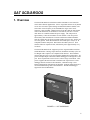
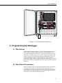
1. Overview
The SAT SCD/ARGOS certified PTT satellite transmitter is well suited for
remote data collection applications. Service Argos data transceivers fly aboard
two or more of NASA’s polar orbiting environmental satellites (POES). The
SCD center carrier frequency is 401.620 MHz, the Argos center carrier
frequency is 401.650 MHz. Channel spacing is 500 Hz. With an orbit altitude
close to 800 kilometers, the satellites are at a relatively low orbit. The low
orbit allows for a smaller antenna and power supply. The orbit period is
approximately 1 hour and 45 minutes for each satellite. This orbit period
allows hourly data transmission at extreme northern and southern latitudes.
Near the equator there are about six POES satellite passes per day, but they are
not evenly spaced. Each data transmission can include up to 32 bytes, or 16
Campbell Scientific data points. Data must be decoded by the user. SCD
satellites follow an equatorial orbit, with satellite passes approximately every
two hours.
The SAT SCD/ARGOS PTT supports up to four Argos ID numbers and four
SCD2 ID numbers. Message repeat intervals, ID numbers and duty cycles can
be changed with a simple-to-use computer-based interface. The transmitter
connects directly to the CS I/O port using the standard SC12 ribbon cable. All
power and input/output connections with the datalogger are through the CS I/O
port. Power requirements can be as low as 2 mA average current drain. After
power is applied, the PTT will start to transmit at the repeat interval. If the
datalogger has not sent data to the transmitter, a default message is sent.
During configuration, transmissions are disabled. Program instruction P125 is
used to send final storage data to the transmitter. The CR10X datalogger
supports the SAT SCD/ARGOS.
Loga
n, Uta
ANTENNA
SAT
SCD
ARG
OS T /ARGO
RA
S
NSM
ASS
EMB
LED
ITTE
IN U
R
SA
SN:
DATALOGGER
h
FIGURE 1-1. SAT SCD/ARGOS
1
SAT SCD/ARGOS
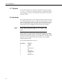
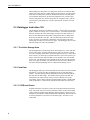
1.1 Physical
The SAT SCD/ARGOS PTT is housed in an aluminum enclosure measuring
3” x 2.75” x 1”. There are two electrical connections. The DB9 port connects
to the datalogger CS I/O port. The SMA female port connects to the 50 ohm
impedance antenna.
1.2 Electrical
The SAT SCD/ARGOS PTT uses the Campbell Scientific Synchronous Device
for Communication (SDC) protocol. The SDC port (DB9 connector) connects
directly to the datalogger serial port (CS I/O), using the supplied SC12 ribbon
cable. The SDC protocol allows other SDC devices to be connected to the
same serial port. Power is supplied via the SC12 cable, pin 1 and pin 8.
NOTE
Not all CR10X wiring panels supply 12 volts to pin 8. The
CR10X wiring panel must include the text: “CR10X wiring
panel”.
The RF connector is an SMA female; nominal output impedance is 50 ohms.
Transmit power is typically one watt. The antenna is omnidirectional, which is
necessary because the target satellites are not geostationary. The Argos center
frequency is 401.650 MHz; the SCD2 center frequency is 401.620 MHz.
Channel spacing is 500 Hz.
The SAT SCD/ARGOS SDC port pin out:
Pin number
1
2
3
4
5
6
7
8
9
2
Function
+5 volts
Ground
NC
TXD (data out)
NC
SDE (input)
CLK/HS (input)
+12 volts
RXD (data in)
SAT SCD/ARGOS
BATT
INT
ON
OFF
EXT
CHG
CHG
+12
+12
G 12V
Logan, Utah
SW 12V CTRL
SE
DIFF
7
8
9
4
G G H
10
5
L AG H
11 12
6
L AG E3 AG G G
L AG H
SW 12V
5V 5V G
G 12V
POWER
IN
CS I/O
G
CR10X WIRING PANEL
MADE IN USA
SE
DIFF
1
2
3
4
5
2
1
G G H
L AG H
6
SDM
3
L AG H
L AG E1 AG E2 G
P1 G P2
G C8 C7 C6 C5 C4 C3 C2 C1
G 12V 12V
EARTH
GROUND
WIRING
PANEL NO.
FIGURE 1-2. SAT SCD/ARGOS with Enclosure
2. Programming the Datalogger
2.1 Data Packets
Before programming the datalogger, you must determine how much data you
will be sending. Each data packet holds 32 bytes; each data point uses two
bytes. With each data point using 2 bytes, you can send 16 data points in each
data packet. The Array ID is not sent. If you are writing a time stamp to final
storage, don’t forget to include the time stamp as additional data points. The
SAT SCD/ARGOS can hold up to four data packets. Each data packet is
transmitted as a single message. High resolution data points are four bytes, but
high resolution data are not supported by the P125 SAT SCD/ARGOS program
instruction.
2.2 Data Packet Transmission
When you setup your Service Argos account and SCD account, you will select
a message repeat interval. The PTT will repeat the message at the repeat
interval until a new message is loaded into the PTT. The Argos transmissions
will be offset from the SCD transmissions by half of the repeat interval if the
repeat interval is the same for both SCD and Argos.
3
SAT SCD/ARGOS
When sending one data packet of 16 data points, the PTT will repeat the data
packet at the repeat interval. When sending two data packets of 16 data points
each, total of 32 data points, the PTT will alternate between each data packet.
If you send four data packets, the PTT will send packet one, wait the repeat
interval, send packet two, wait the repeat interval, send packet three, wait the
repeat interval, send packet four, wait the repeat interval, and start over with
packet one.
2.3 Datalogger Instruction 125
The datalogger uses P125 to send data to the PTT. All new data, up to 64 data
points, in the active storage area, are sent to the PTT. New data is all data that
has been written to the active final storage area since P125 last executed. If
there are more data than 64 data points (4 data packets times 16 data points),
P125 does not send the extra data. The extra data will be sent the next time
P125 is executed. You must not continuously write more data to the active
final storage area than you can send over Argos. The datalogger does not erase
data after it has been sent to the transmitter.
2.3.1 The Active Storage Area
The datalogger has two final storage areas, final storage area 1 (FS1) and final
storage area 2 (FS2). Program instruction 80 is used to set the active storage
area. By controlling where data is written and what storage area is active when
P125 executes, you can keep two separate data files. This can be useful if you
want to collect and store more data than you can transmit. FS1 is the default
storage area. The datalogger always defaults to FS1 at the top of the program
table. If you plan to use FS2, you must allocate memory to FS2. Memory for
FS2 can be allocated in Edlog; click on “Options/Final Storage Area 2”.
2.3.2 New Data
The datalogger must keep track of what data has been sent to the PTT and what
data has not. To track new data, the datalogger keeps several data storage
pointers. The Data Storage Pointer (DSP) points to the first location past the
last data value in final storage. The Satellite Pointer points to the first data
location that was written since P125 last executed. When P125 executes
successfully, all new data is transferred and the satellite pointer is updated and
points to the DSP, or 1 data location past the last data value sent to the PTT.
2.3.3 P125 Result Codes
Program instruction 125 returns a result code to the input location specified in
P125. The result code can be used to determine if P125 executed successfully.
Under certain circumstances the datalogger cannot properly execute P125; for
example, the PTT blocks communications while transmitting. Result codes can
be used to determine if you need to execute P125 again. See Table 2-1 for
result codes.
4
SAT SCD/ARGOS
2.3.4 Using Result Codes in the Program
After P125 has executed, check the result codes. If the result code is greater
than or equal to two, execute P125 again. Recheck the result code on the next
pass of the program table. Example Algorithm:
If time to write data
Write data to Final Storage
Execute P125
Use P89 to determine if result code >= 2
If true execute P125
end (P95)
2.3.5 When to Execute P125
Usually P125 is only executed after data has been written to final storage.
While this is not critical, it makes more sense. When P125 sends new data to
the PTT, all data in the PTT is replaced. If P125 is executed when there is no
new data in final storage, P125 returns a result code of 1. Existing data is not
removed from the PTT.
TABLE 2-1. P125 Result Codes
Result Code
0
1
2
3
4
5
6
Code Meaning
Normal response, transmitter on line and data packet received
No new data in datalogger active final storage area
No response from the transmitter, transmitter may be
transmitting
Improper response from transmitter
Data packet not properly received by transmitter
Transmitter timed out before data packet was received
Datalogger serial port not available, probably in use by another
device
2.4 Program Example
;{CR10X}
;
*Table 1 Program
01: 10
Execution Interval (seconds)
; Load values in input locations
1: Bulk Load (P65)
1: 11
F
2: 22
F
3: 33
F
4: 44
F
5: 55
F
6: 66
F
7: 77
F
8: 88
F
9: 3
Loc [ Start_1 ]
5
SAT SCD/ARGOS
; Load more values in input locations
2: Bulk Load (P65)
1: 99
F
2: 101
F
3: 102
F
4: 103
F
5: 104
F
6: 105
F
7: 106
F
8: 107
F
9: 11
Loc [ Start_9 ]
; If top of the hour, write 16 data point to FS1
3: If time is (P92)
1: 0
Minutes (Seconds --) into a
2: 60
Interval (same units as above)
3: 10
Set Output Flag High (Flag 0)
4: Real Time (P77)
1: 1220
Year,Day,Hour/Minute (midnight = 2400)
5: Sample (P70)
1: 13
Reps
2: 3
Loc [ Start_1 ]
; If top of the hour, transfer all new data to the SAT SCD/ARGOS transmitter
6: If time is (P92)
1: 0
Minutes (Seconds --) into a
2: 60
Interval (same units as above)
3: 30
Then Do
7: SCD2/ARGOS (P125)
1: 19
Return Code Loc [ R_Code
]
8: End (P95)
; Check result of P125, if greater than 1 execute P125 again
9: If (X<=>F) (P89)
1: 19
X Loc [ R_Code
2: 3
>=
3: 2
F
4: 30
Then Do
]
10: SCD2/ARGOS (P125)
1: 19
Return Code Loc [ R_Code
11: End (P95)
*Table 2 Program
02: 0.0000
Execution Interval (seconds)
*Table 3 Subroutines
End Program
6
]
SAT SCD/ARGOS
3. SAT SCD/ARGOS Configuration
The SAT SCD/ARGOS PTT must be configured before you deploy it. Two
numbers are used to track your data through the system. The first number is
your Program ID, the second number is your SCD/Argos ID. The PTT can use
up to 4 SCD numbers and up to 4 ARGOS ID numbers. You must have your
SCD/Argos ID numbers before you can configure your PTT. The SCD/Argos
ID number and transmission repetition rate is written to the SAT SCD/ARGOS
PTT during configuration.
3.1 SAT SCD/ARGOS Power Supply
During configuration, the PTT is powered through the SC532A. For a power
supply the SC532A uses a 12 volt DC wall regulator/transformer or a direct
connection to a 12 volt battery. The SC532A has an internal jumper. The
jumper changes the operational mode of the SC532A. In the “PROG” or
program mode, the SC532A will provide the interface between a computer and
the SAT SCD/ARGOS. The SC532 mode is used for storage modules. When
using the SC532A to configure the SAT SCD/ARGOS transmitter, configure
the jumper for “PROG”.
NOTE
The SC532 will not work in place of the SC532A.
3.2 Pttcomm.exe
Included with each SAT SCD/ARGOS is a disk containing support software.
The information on the disk should be copied to a computer. Load the disk in
the disk drive and execute “Setup.exe”.
The computer must have a working RS 232 port. Pttcomm.exe is a 32 bit
windows-based program. Run Pttcomm.exe; use “File/Open” to open the
configuration file “SCD_Argos.cfg”.
Edit your SCD/Argos ID number, or numbers if you are using more than one.
By setting an ID number to zero, the buffer is turned off. All buffers not being
used should be set to zero.
Scroll down to “SCD Transmission Rep Rate” and “Argos Transmission Rep
Rate”. Enter the appropriate repetition rate for each field.
The Argos channel number and SCD2 channel number can be set to a value
between 0 and 10. Channel 5 is the center channel.
In most cases, “Transmission On Time” and “Transmission Off Time” will not
need to be changed. Transmission on time is the time the transmitter continues
to send bursts of data at the transmission repetition rates. Transmission off time
is the amount of time the PTT is shut down after the transmission on time has
been completed. Transmission on/off time starts when the PTT is powered up.
Transmission on and off time can be used to control the duty cycle of the
transmitter. The transmission off time is not synchronized with the time of day.
7
SAT SCD/ARGOS
The shut down timer will turn the PTT off after the shut down time has expired.
The PTT will not turn back on. Set the shut down timer to zero for extended
operation.
Save the configuration file to a new name. From the PTTComm menu bar,
select File, Save As and save the file to a new name. You may need the
original configuration file at a later date.
3.2.1 Loading the Configuration to the PTT
Assemble the hardware. You need the SAT SCD/ARGOS PTT, the SC532A
with power supply, and two serial cables (SC12). Before you apply power, you
should have a dummy load or antenna connected to the RF output of the SAT
SCD/ARGOS. Do not apply power to the SAT SCD/ARGOS yet. Make the
following connections:
1) PTT to SC532A using the SC12 ribbon cable.
2) SC532A to the PC using an RS232 cable.
3) Antenna or dummy load to the PTT RF output.
4) Connect AC transformer/12 volt DC supply to power source, but don’t
connect to the SC532A.
After power is applied to the PTT, it will start to transmit. Don’t let the PTT
transmit until you have the configuration loaded. Many times a transmission
from inside a building will be picked up by a satellite. To avoid unwanted
transmissions, do not apply power to the PTT before the configuration program
(Pttcomm.exe) is ready.
On the PC, load Pttcomm.exe. Click “File/preferences”. Set the correct
communications port. Also, set the baud rate to 9600. Everything else should
be left to the default values of: UI Exit string = QQQQQQG, Platform =
WildCAT, Prompt Wait (In Seconds) = 70, Verify data as it is Written and
Simple Mode not checked.
Click on file and open the configuration file “SCD_Argos.cfg”, if it is not
already open.
Click on the start button. Apply power to the SC532A; this will power the
transmitter. When the PTT is first powered, it sends a start up message out the
serial port. When Pttcomm.exe receives a startup message, the PTT is put in
configuration mode. Pttcomm.exe will give a message when the PTT and the
computer have established communications. Click on the “Cfg” button to send
the configuration file. In a moment the software will acknowledge the file was
sent. Wait at least ten seconds before you close Pttcomm.exe or power down
the PTT.
4. Satellite Orbit Patterns
At least two POES satellites carry the Argos transceivers and are operational at
any given time. The orbits carry the satellites over the North and South poles
of the earth in a sun synchronous pattern. Orbit period is close to 102 minutes.
The satellite footprint is about 5000 km in diameter. At latitudes greater than
75 degrees, each satellite provides coverage each pass. Each satellite passes
8
SAT SCD/ARGOS
over the poles 14 times a day providing 28 satellite passes per day. Coverage
decreases with latitude. At the equator the PTT will “see” a satellite six or
seven times a day. The SCD2 satellites are in a different orbit pattern than the
POES satellites.
The duration of the POES satellite visibility depends on the angle from the PTT
to the satellite. If the satellite passes directly overhead, the satellite will be
visible for about 15 minutes. If the satellite passes close to the horizon, as
viewed from the PTT, the satellite will only be visible for a short time. On
average, each satellite pass is visible for about ten minutes. If using a 200
second repetition rate, a satellite pass could result in three received messages
from the PTT.
Satellite coverage must be considered when planning data collection and
transmission. Given the variability of satellite coverage, hourly data cannot be
expected unless the PTT is located above 75 degrees latitude. The number of
successful data transmissions per satellite pass will increase with a decrease in
the repetition rate.
More detailed information regarding Service Argos and satellite coverage is
available from Service Argos. On the Web, see http://www.argosinc.com/.
The Service Argos North American office can be contacted by email at
[email protected] or phone (301) 925-4411.
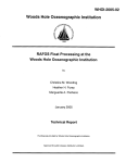
5. Antenna Placement
The position of polar orbiting satellites relative to the PTT will change during
the satellite pass and with each satellite pass. The antenna must broadcast
evenly to all areas of the sky. The antenna is omnidirectional. Mount the
antenna vertically. Choose a location with a clear view of the sky in all
directions. Any obstruction between the PTT antenna and the sky can block
data transmission between the satellite and the PTT.
13904 Antenna
Enclosure houses
the transmitter,
datalogger, and
power supply
FIGURE 5-1. Complete Weather Station with PTT
This is a blank page.
9
SAT SCD/ARGOS
10