1
CÓPIA NÃO CONTROLADA
G176/G177/G176L
SERVICE MANUAL
003037MIU
CÓPIA NÃO CONTROLADA
CÓPIA NÃO CONTROLADA
CÓPIA NÃO CONTROLADA
CÓPIA NÃO CONTROLADA
G176/G177/G176L
SERVICE MANUAL
CÓPIA NÃO CONTROLADA
CÓPIA NÃO CONTROLADA
CÓPIA NÃO CONTROLADA
CÓPIA NÃO CONTROLADA
G176/G177/G176L
SERVICE MANUAL
003037MIU
CÓPIA NÃO CONTROLADA
CÓPIA NÃO CONTROLADA
CÓPIA NÃO CONTROLADA
CÓPIA NÃO CONTROLADA
It is the reader's responsibility when discussing the information contained
within this document to maintain a level of confidentiality that is in the best
interest of Ricoh Corporation and its member companies.
NO PART OF THIS DOCUMENT MAY BE REPRODUCED IN ANY
FASHION AND DISTRIBUTED WITHOUT THE PRIOR
PERMISSION OF RICOH CORPORATION.
All product names, domain names or product illustrations, including
desktop images, used in this document are trademarks, registered
trademarks or the property of their respective companies.
They are used throughout this book in an informational or editorial fashion
only and for the benefit of such companies. No such use, or the use of
any trade name, or web site is intended to convey endorsement or other
affiliation with Ricoh products.
© 2007 RICOH Corporation. All rights reserved.
CÓPIA NÃO CONTROLADA
CÓPIA NÃO CONTROLADA
CÓPIA NÃO CONTROLADA
CÓPIA NÃO CONTROLADA
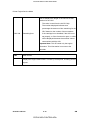
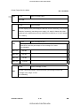
WARNING
The Service Manual contains information
regarding service techniques, procedures,
processes and spare parts of office equipment
distributed by Ricoh Corporation. Users of this
manual should be either service trained or
certified by successfully completing a Ricoh
Technical Training Program.
Untrained and uncertified users utilizing
information contained in this service manual to
repair or modify Ricoh equipment risk personal
injury, damage to property or loss of warranty
protection.
Ricoh Corporation
CÓPIA NÃO CONTROLADA
CÓPIA NÃO CONTROLADA
CÓPIA NÃO CONTROLADA
CÓPIA NÃO CONTROLADA
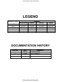
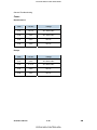
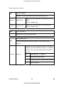
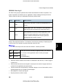
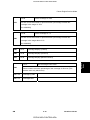
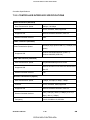
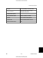
LEGEND
PRODUCT CODE
G176
G177
G176L
GESTETNER
P7031n
P7035n
P7031nL
COMPANY
LANIER
RICOH
LP131n
SP 4100N
LP136n
SP 4110N
LP131nL
Aficio SP 4100NL
SAVIN
MLP31n
MLP36n
MLP31nL
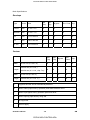
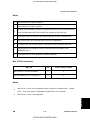
DOCUMENTATION HISTORY
REV. NO.
*
1
DATE
03/2007
5/2008
COMMENTS
Original Printing
G176L Addition
CÓPIA NÃO CONTROLADA
CÓPIA NÃO CONTROLADA
CÓPIA NÃO CONTROLADA
CÓPIA NÃO CONTROLADA
G176/G177/G176L
TABLE OF CONTENTS
INSTALLATION
1. INSTALLATION .......................................................................1-1
1.1 INSTALLATION REQUIREMENTS.......................................................1-1
1.1.1 ENVIRONMENT ..........................................................................1-1
1.1.2 MACHINE LEVEL ........................................................................1-2
1.1.3 REQUIRED SPACE .....................................................................1-2
1.1.4 POWER SUPPLY ........................................................................1-2
1.2 MACHINE INSTALLATION ...................................................................1-3
1.3 DATA OVERWRITE SECURITY UNIT INSTALLATION .......................1-4
1.3.1 INSTALLATION ...........................................................................1-4
1.3.2 CHECKING AND COMPLETING THE INSTALLATION ..............1-5
PREVENTIVE MAINTENANCE
2. PREVENTIVE MAINTENANCE ...............................................2-1
2.1 USER MAINTENANCE .........................................................................2-1
2.2 SERVICE MAINTENANCE ...................................................................2-2
REPLACEMENT AND ADJUSTMENT
3. REPLACEMENT AND ADJUSTMENT ....................................3-1
3.1 GENERAL.............................................................................................3-1
3.1.1 PRECAUTIONS ON DISASSEMBLY ..........................................3-1
3.1.2 RELEASING PLASTIC LATCHES ...............................................3-2
3.1.3 AFTER SERVICING THE MACHINE ...........................................3-3
3.2 SPECIAL TOOLS..................................................................................3-4
3.3 COVERS...............................................................................................3-5
3.3.1 FRONT COVER...........................................................................3-5
3.3.2 UPPER COVER...........................................................................3-5
SM
i
CÓPIA NÃO CONTROLADA
G176/G177/G176L
CÓPIA NÃO CONTROLADA
3.3.3 BY-PASS TRAY UNIT .................................................................3-6
3.3.4 EXTERIOR COVERS ..................................................................3-6
3.4 LASER UNIT .........................................................................................3-7
3.4.1 CAUTION DECAL LOCATIONS ..................................................3-7
3.4.2 POLYGON MIRROR MOTOR .....................................................3-7
3.4.3 LASER SYNCHRONIZATION DETECTOR .................................3-8
3.4.4 LASER UNIT................................................................................3-9
3.4.5 LASER DIODE UNIT .................................................................3-10
3.4.6 LASER BEAM PITCH ADJUSTMENT .......................................3-10
3.5 TRANSFER ROLLER .........................................................................3-13
3.6 TONER END SENSOR.......................................................................3-14
3.7 FUSING ..............................................................................................3-15
3.7.1 FUSING UNIT ............................................................................3-15
3.7.2 HOT ROLLER AND FUSING LAMP ..........................................3-16
3.7.3 PRESSURE ROLLER ................................................................3-18
3.7.4 THERMISTOR AND THERMOSTAT .........................................3-18
3.7.5 HOT ROLLER STRIPPERS.......................................................3-19
3.8 PAPER FEED .....................................................................................3-20
3.8.1 PAPER FEED ROLLER .............................................................3-20
3.8.2 FRICTION PAD..........................................................................3-21
3.9 BY-PASS TRAY ..................................................................................3-22
3.10 PRINTER CONTROLLER BOARD ...................................................3-23
3.11 ENGINE BOARD...............................................................................3-24
3.12 MAIN MOTOR...................................................................................3-25
3.13 CLUTCHES.......................................................................................3-26
3.14 PSU, HVPS.......................................................................................3-27
3.15 COOLING FAN .................................................................................3-28
TROUBLESHOOTING
4. TROUBLESHOOTING .............................................................4-1
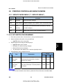
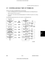
4.1 SERVICE CALL CONDITIONS .............................................................4-1
4.1.1 SUMMARY...................................................................................4-1
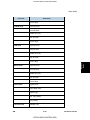
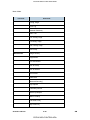
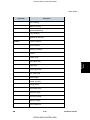
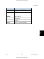
4.1.2 SC CODE DESCRIPTIONS.........................................................4-2
4.2 ERROR MESSAGES ..........................................................................4-18
4.3 GENERAL TROUBLESHOOTING ......................................................4-25
G176/G177/G176L
ii
CÓPIA NÃO CONTROLADA
SM
CÓPIA NÃO CONTROLADA
4.3.1 IMAGE ADJUSTMENT ..............................................................4-25
Registration Adjustment ................................................................4-25
Parallelogram Image Adjustment ..................................................4-25
4.3.2 ELECTRICAL DEFECTS ...........................................................4-26
Fuses ............................................................................................4-28
4.3.3 SKEW ADJUSTMENT ...............................................................4-29
4.3.4 STREAKS IN THE SUB SCAN DIRECTION..............................4-29
4.3.5 MISCELLANEOUS PROBLEMS................................................4-30
SERVICE TABLES
5. SERVICE TABLES...................................................................5-1
5.1 SERVICE PROGRAM MODE ...............................................................5-1
5.1.1 SERVICE PROGRAM MODE: OVERVIEW.................................5-1
Entering the Service Mode ..............................................................5-1
Setting a Service Program...............................................................5-2
Exiting Service Mode.......................................................................5-2
5.2 PRINTER CONTROLLER SERVICE MODE ........................................5-3
5.2.1 SERVICE MODE MENU ("1. SERVICE MENU").........................5-3
5.2.2 BIT SWITCH PROGRAMMING ...................................................5-3
5.3 PRINTER ENGINE SERVICE MODE ...................................................5-4
5.3.1 SERVICE MODE TABLE .............................................................5-4
SP1-xxx: Feed.................................................................................5-4
SP2-xxx: Drum ..............................................................................5-10
SP3-xxx: Process ..........................................................................5-12
SP5-xxx: Mode ..............................................................................5-14
SP7-xxx: Data Log ........................................................................5-56
SP8XXX: Data Log 2.....................................................................5-71
5.4 FIRMWARE UPDATE .........................................................................5-82
5.4.1 TYPE OF FIRMWARE ...............................................................5-82
5.4.2 PRECAUTIONS .........................................................................5-82
Handling SD Cards........................................................................5-82
Upload/Download ..........................................................................5-83
Network Connection ......................................................................5-83
5.4.3 MACHINE FIRMWARE UPDATE ..............................................5-83
5.5 NVRAM DATA UPLOAD/DOWNLOAD...............................................5-85
SM
iii
CÓPIA NÃO CONTROLADA
G176/G177/G176L
CÓPIA NÃO CONTROLADA
5.5.1 UPLOADING NVRAM DATA .....................................................5-85
5.5.2 DOWNLOADING NVRAM DATA ...............................................5-86
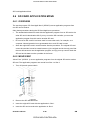
5.6 SD CARD APPLICATION MOVE........................................................5-88
5.6.1 OVERVIEW................................................................................5-88
5.6.2 MOVE EXEC..............................................................................5-88
5.6.3 UNDO EXEC..............................................................................5-89
5.7 CONTROLLER SELF TEST AT POWER-ON .....................................5-91
5.8 MENU MODE......................................................................................5-92
5.9 CONTROLLER BOARD DIP SWITCHES ...........................................5-98
DETAILED DESCRIPTIONS
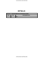
6. DETAILS ..................................................................................6-1
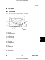
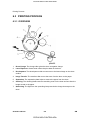
6.1 OVERVIEW...........................................................................................6-1
6.1.1 MECHANICAL COMPONENT LAYOUT ......................................6-1
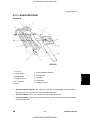
6.1.2 PAPER PATH ..............................................................................6-2
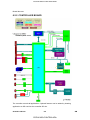
6.2 BOARD STRUCTURE ..........................................................................6-3
6.2.1 BLOCK DIAGRAM .......................................................................6-3
6.2.2 CONTROLLER BOARD...............................................................6-4
6.3 PRINTING PROCESS ..........................................................................6-6
6.3.1 OVERVIEW..................................................................................6-6
6.3.2 LASER EXPOSURE ....................................................................6-7
Overview .........................................................................................6-7
Automatic Power Control (APC) ......................................................6-8
LD Safety Mechanisms ...................................................................6-9
6.3.3 CARTRIDGE OVERVIEW..........................................................6-10
6.3.4 DRUM CHARGE........................................................................6-10
6.3.5 DEVELOPMENT........................................................................6-11
Toner Supply and Development ....................................................6-11
Toner Density Control ...................................................................6-12
6.3.6 TONER END DETECTION ........................................................6-13
Overview .......................................................................................6-13
Toner End Sensor .........................................................................6-13
Main Motor Rotation Count............................................................6-14
Toner Overflow Prevention............................................................6-14
Summary .......................................................................................6-15
G176/G177/G176L
iv
CÓPIA NÃO CONTROLADA
SM
CÓPIA NÃO CONTROLADA
6.4 PAPER FEED .....................................................................................6-18
6.4.1 OVERVIEW................................................................................6-18
6.4.2 PAPER TRAY ............................................................................6-20
Tray Extension ..............................................................................6-20
Paper Lift .......................................................................................6-21
Paper Feed and Registration.........................................................6-21
Paper Size Detection.....................................................................6-22
Paper End Detection .....................................................................6-23
Remaining Paper Detection...........................................................6-23
6.4.3 BY-PASS TRAY.........................................................................6-24
6.5 IMAGE FUSING AND PAPER EXIT ...................................................6-25
6.5.1 OVERVIEW................................................................................6-25
6.5.2 FUSING DRIVE .........................................................................6-26
6.5.3 FUSING ENTRANCE AND GUIDE SHAFT ...............................6-26
6.5.4 PRESSURE ROLLER ................................................................6-27
6.5.5 NEW FUSING UNIT DETECTION .............................................6-28
6.5.6 FUSING TEMPERATURE CONTROL .......................................6-29
Overheat Protection ......................................................................6-30
6.5.7 PAPER EXIT..............................................................................6-31
6.5.8 ENERGY SAVER MODE ...........................................................6-32
6.6 CONTROLLER FUNCTIONS..............................................................6-33
SPECIFICATIONS
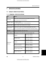
7. SPECIFICATIONS....................................................................7-1
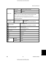
7.1 BASIC SPECIFICATIONS ....................................................................7-1
7.1.1 GENERAL SPECIFICATIONS .....................................................7-1
7.1.2 EXTERNAL OPTIONS .................................................................7-4
7.1.3 PAPER SIZES .............................................................................7-5
Plain Paper......................................................................................7-5
Envelope .........................................................................................7-6
Custom ............................................................................................7-6
Envelopes........................................................................................7-7
7.1.4 OPERATING ENVIRONMENT ....................................................7-8
7.1.5 OPERATION PANEL LED SPECIFICATIONS ..........................7-10
7.2 CONTROLLER SPECIFICATIONS.....................................................7-11
SM
v
CÓPIA NÃO CONTROLADA
G176/G177/G176L
CÓPIA NÃO CONTROLADA
7.2.1 CONTROLLER BOARD.............................................................7-11
7.2.2 PRINTING FUNCTIONS ............................................................7-12
7.2.3 PRINTER DRIVERS ..................................................................7-13
7.2.4 SUPPORTED ENVIRONMENTS...............................................7-16
Windows Environments .................................................................7-16
Notes.............................................................................................7-17
Mac OS Environments ..................................................................7-17
Notes.............................................................................................7-17
UNIX Environment.........................................................................7-18
Novell Netware ..............................................................................7-18
SAP R/3 Environment ...................................................................7-19
7.2.5 CONTROLLER INTERFACE SPECIFICATIONS ......................7-20
7.2.6 SUPPORTED UTILITIES ...........................................................7-22
Bundled Utilities.............................................................................7-22
Optional Utilities ............................................................................7-22
7.3 MACHINE CONFIGURATION ............................................................7-23
7.3.1 SYSTEM COMPONENTS..........................................................7-23
G893 DUPLEX UNIT AD1000
SEE SECTION G893 FOR DETAILED TABLE OF CONTENTS
G894 PAPER FEED UNIT TK1030 &
G362 ENVELOPE FEEDER TYPE 400
SEE SECTION G894/G362 FOR DETAILED TABLE OF CONTENTS
G176/G177/G176L
vi
CÓPIA NÃO CONTROLADA
SM
CÓPIA NÃO CONTROLADA
TROUBLESHOOTING
SERVICE TABLES
G893 DUPLEX UNIT AD1000
DETAILED DESCRIPTIONS
TAB
POSITION 3
TAB
POSITION 8
TAB
POSITION 7
SPECIFICATIONS
TAB
POSITION 4
REPLACEMENT AND ADJUSTMENT
TAB
POSITION 5
G894 PAPER FEED UNIT TK1030/G362 ENVELOPE
FEEDER TYPE 400
TAB
POSITION 6
PREVENTIVE MAINTENANCE
TAB
POSITION 2
TAB
POSITION 1
INSTALLATION
CÓPIA NÃO CONTROLADA
CÓPIA NÃO CONTROLADA
CÓPIA NÃO CONTROLADA
CÓPIA NÃO CONTROLADA
Read This First
Safety, Conventions, Trademarks
Safety
PREVENTION OF PHYSICAL INJURY
1.
Before disassembling or assembling parts of the printer and peripherals, make sure
that the printer power cord is unplugged.
2.
The wall outlet should be near the printer and easily accessible.
3.
Note that some components of the printer and the paper tray unit are supplied with
electrical voltage even if the main power switch is turned off.
4.
If any adjustment or operation check has to be made with exterior covers off or open
while the main switch is turned on, keep hands away from electrified or mechanically
driven components.
5.
The inside and the metal parts of the fusing unit become extremely hot while the printer
is operating. Be careful to avoid touching those components with your bare hands.
6.
To prevent a fire or explosion, keep the machine away from flammable liquids, gases,
and aerosols.
HEALTH SAFETY CONDITIONS
Toner and developer are non-toxic, but if you get either of them in your eyes by accident, it
may cause temporary eye discomfort. Try to remove with eye drops or flush with water as
first aid. If unsuccessful, get medical attention.
OBSERVANCE OF ELECTRICAL SAFETY STANDARDS
The printer and its peripherals must be installed and maintained by a customer service
representative who has completed the training course on those models.
SAFETY AND ECOLOGICAL NOTES FOR DISPOSAL
1.
Do not incinerate toner bottles or used toner. Toner dust may ignite suddenly when
exposed to an open flame.
2.
Dispose of used toner, developer, and organic photoconductors in accordance with
local regulations. (These are non-toxic supplies.)
3.
Dispose of replaced parts in accordance with local regulations.
4.
When keeping used lithium batteries in order to dispose of them later, do not put more
than 100 batteries per sealed box. Storing larger numbers or not sealing them apart
may lead to chemical reactions and heat build-up.
CÓPIA NÃO CONTROLADA
CÓPIA NÃO CONTROLADA
!
The controller board in this machine contains a lithium battery.
!
The danger of explosion exists if a battery of this type is incorrectly replaced.
Replace only with the same or an equivalent type of battery recommended by the
manufacturer.
!
Dispose of batteries in accordance with the manufacturer's instructions and local
laws and regulations.
LASER SAFETY
The Center for Devices and Radiological Health (CDRH) prohibits the repair of laser-based
optical units in the field. The optical housing unit can only be repaired in a factory or at a
location with the requisite equipment. The laser subsystem is replaceable in the field by a
qualified Customer Engineer. The laser chassis is not repairable in the field. Customer
engineers are therefore directed to return all chassis and laser subsystems to the factory or
service depot when replacement of the optical subsystem is required.
!
Use of controls, or adjustment, or performance of procedures other than those
specified in this manual may result in hazardous radiation exposure.
!
Turn off the main switch before attempting any of the procedures in the Laser Unit
section. Laser beams can seriously damage your eyes.
Caution Labels
CÓPIA NÃO CONTROLADA
CÓPIA NÃO CONTROLADA
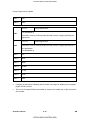
Conventions and Trademarks
Conventions
Symbol
What it means
☛
Refer to section number
!
See Core Tech Manual for details
"
Screw
#
Connector
$
E-ring
%
C-ring
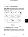
The following notations are used in text to describe the direction of paper feed: lengthwise
and sideways. The annotations “SEF” and “LEF” denote “Short Edge Feed” and “Long
Edge Feed". (The arrows indicate the direction of paper feed.)
Trademarks
Microsoft®, Windows®, and MS-DOS® are registered trademarks of Microsoft Corporation
in the United States and /or other countries.
PostScript® is a registered trademark of Adobe Systems, Incorporated.
PCL® is a registered trademark of Hewlett-Packard Company.
Ethernet® is a registered trademark of Xerox Corporation.
PowerPC® is a registered trademark of International Business Machines Corporation.
Other product names used herein are for identification purposes only and may be
trademarks of their respective companies. We disclaim any and all rights involved with
those marks. This manual uses several symbols and some simple abbreviations.
CÓPIA NÃO CONTROLADA
CÓPIA NÃO CONTROLADA
CÓPIA NÃO CONTROLADA
CÓPIA NÃO CONTROLADA
INSTALLATION
SECTION 1
Page
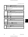
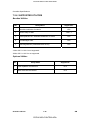
INSTALLATION REVISION HISTORY
Date
Added/Updated/New
None
CÓPIA NÃO CONTROLADA
CÓPIA NÃO CONTROLADA
CÓPIA NÃO CONTROLADA
CÓPIA NÃO CONTROLADA
Installation
Installation Requirements
1. INSTALLATION
1.1 INSTALLATION REQUIREMENTS
1.1.1 ENVIRONMENT
Temperature/Humidity
Acceptable: 10C (50F) 15% to 27C (80.6F) 80%
Ranges:
Recommended (Office): 15C (59F) 30% to 25C (77F) 70%
Ambient Illumination:
Less than 2000 lux (do not expose to direct sunlight).
Ventilation:
3 times/hr/person
1.
Avoid areas that are exposed to sudden temperature changes. This includes:
Areas directly exposed to cool air from an air conditioner.
Areas directly exposed to heat from a heater.
2.
Do not install this machine in an area where it will be exposed to corrosive gases.
3.
Do not install the machine at locations over 2,500 m (8,125 ft.) above sea level.
4.
Put the machine on a strong and level base. Inclination on any side should not exceed
5 mm.
5.
SM
Do not put the machine where it may be subjected to strong vibrations.
1-1
CÓPIA NÃO CONTROLADA
G176/G177/G176L
CÓPIA NÃO CONTROLADA
Installation Requirements
1.1.2 MACHINE LEVEL
Front to back:
Within 5 mm. (0.2 inches) of level.
Right to left:
Within 5 mm. (0.2 inches) of level.
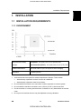
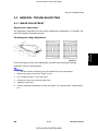
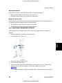
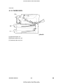
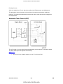
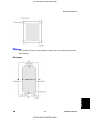
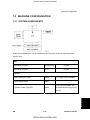
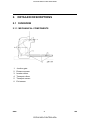
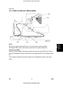
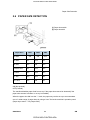
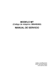
1.1.3 REQUIRED SPACE
Place the machine near the power source, providing the clearance as shown below:
A: Over 10 cm (4 inches)
B: Over 10 cm (4 inches)
C: Over 40 cm (15.8 inches)
D: Over 10 cm (4 inches)
1.1.4 POWER SUPPLY
Make sure the plug is firmly inserted in the outlet.
Avoid multi-wiring.
Be sure to ground the machine.
Input voltage level
NA: 120 volts, 60 Hz
EU: 220-240 volts, 50 Hz/60 Hz
Permitted voltage
Fluctuation: ±10 %
Never place anything on the power cord.
G176/G177/G176L
1-2
CÓPIA NÃO CONTROLADA
SM
CÓPIA NÃO CONTROLADA
Installation
Machine Installation
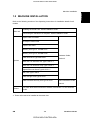
1.2 MACHINE INSTALLATION
Refer to the following sections of the Operating Instructions for installation details for all
models.
Main unit
Installing the Printer Unit: Quick Installation Guide.
Connecting the machine to a computer: Quick Installation Guide
Paper Feed Unit G894
Envelope Feeder G362
Duplex Unit G893
Memory Unit Type C 128 MB G331
Memory Unit Type C 256 MB G332
Hard Disk Drive Type 2650 M311
Options
Hardware Guide,
Section 2
IEEE 802.11b interface Unit Type H G813 *1
IEEE 802.11b Interface Unity Type I G874 *1
Gigabit Ethernet Board Type A G874 *1
VM Card Type D G874
Data Storage Card Type A G874
Data Overwrite Security Unit Type E G874
See next section of this
manual.
Drivers
For more about drivers and other software, see Section 1 of the Software
Guide.
*1 These units cannot be installed at the same time.
SM
1-3
CÓPIA NÃO CONTROLADA
G176/G177/G176L
CÓPIA NÃO CONTROLADA
Data Overwrite Security Unit Installation
1.3 DATA OVERWRITE SECURITY UNIT
INSTALLATION
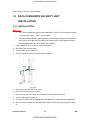
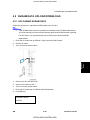
1.3.1 INSTALLATION
The correct number and type for this installation is Type E. Do not attempt to install
any other type (Type C, Type D, for example).
The SD card that holds the DOS application must always reside in SD card slot C2.
(This can be the original SD or another SD card where the DOS (Data Overwrite
Security) application has been moved with SP5873.)
1.
If the machine is on, turn off the main power switch.
2.
Disconnect the network cable.
3.
Turn the main power switch on.
4.
Turn the operation switch and main power switch off.
5.
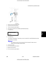
Remove the SD card slot cover (x1).
6.
Insert the DOS SD card into Slot 2.
7.
Reconnect the network cable, if the network is connected to the copier.
8.
Turn the main power switch on.
9.
Enter the SP mode and do SP5878 and push [#Enter] to enable the DOS application.
10. Go out of the SP mode, turn the operation switch off, then turn the main power switch
off.
G176/G177/G176L
1-4
CÓPIA NÃO CONTROLADA
SM
CÓPIA NÃO CONTROLADA
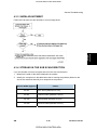
1.3.2 CHECKING AND COMPLETING THE INSTALLATION
Do this procedure to confirm that the data overwrite security feature is enabled and
operating.
1.
Turn the machine power on.
2.
Do SP5990 005 (Diagnostic Report) to print the diagnostic report.
3.
Check the diagnostic report.
Under [ROM No./Firmware Version] you should see "B7355060/0.03" displayed
for "HDD Format Option".
Under [Loading Program] you should see "GW1a_zoffy:B7355060/0.03"
Important
The numbers in the diagnostic report must match. (The ROM number and
firmware version number change after the firmware has been upgraded.)
If the ROM numbers or version numbers do not match, this means that the DOS
unit type was incorrect (not "Type E"),
If this occurs:
(1)
Obtain the Type E DOS unit card or confirm that the DOS unit is Type E.
(2)
Replace the NVRAM on the controller board.
(3)
Insert the Type E DOS unit SD card in Slot 2.
(4)
Do the DOS unit installation procedure again.
4.
Push and release in this order: [#Enter]> [Escape]> [Menu].
5.
Push [%] or [#] to display "Maintenance" then push [#Enter].
6.
Push [%] or [#] to display "Memory Erase" and "Erase All Mem."
7.
If you see "Memory Erase" and "Erase All Mem." in the selections, then the DOS
application has been enabled and is operating.
SM
1-5
CÓPIA NÃO CONTROLADA
G176/G177/G176L
Installation
Data Overwrite Security Unit Installation
CÓPIA NÃO CONTROLADA
CÓPIA NÃO CONTROLADA
CÓPIA NÃO CONTROLADA
PREVENTIVE MAINTENANCE
SECTION 2
Page
PREVENTIVE MAINTENANCE REVISION HISTORY
Date
Added/Updated/New
None
CÓPIA NÃO CONTROLADA
CÓPIA NÃO CONTROLADA
CÓPIA NÃO CONTROLADA
CÓPIA NÃO CONTROLADA
User Maintenance
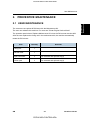
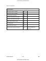
2. PREVENTIVE MAINTENANCE
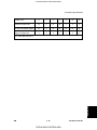
The customer can replace all PM items with the Maintenance Kit.
The user can maintain this machine. For more see "Printer Engine Service Mode".
The operation panel shows “Replace Maintenance Kit” when the PM counter reaches 90K.
After the user replaces the fusing unit in the maintenance kit, the machine automatically
resets the PM counter.
Item
Quantity
Remarks
Fusing unit
1
Transfer roller
1
Paper feed roller
3
For standard and optional tray(s)
Friction pad
3
For standard and optional tray(s)
SM
2-1
CÓPIA NÃO CONTROLADA
G176/G177/G176L
Preventive
Maintenance
2.1 USER MAINTENANCE
CÓPIA NÃO CONTROLADA
Service Maintenance
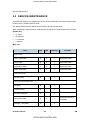
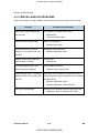
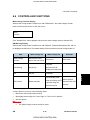
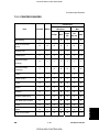
2.2 SERVICE MAINTENANCE
To enable the machine for maintenance by the service technician, the meter-charge mode
must be set to “enabled” with SP5930.
The table below shows the PM items serviced by the service technician.
After completing a PM procedure, reset the PM counter for the replaced part with SP7-804.
Symbol key:
C: Clean
R: Replace
L: Lubricate
I: Inspect
Main unit
Item
90K
EM
Quantity
Remarks
Paper Feed Roller
R
C
1
Clean with water
Friction Pad
R
C
1
Clean with water
Registration Roller
C
C
1
Clean with water
Bottom Plate Pad
C
C
1
Clean with water
Paper Feed
Around the Drum
Transfer Roller
R
1
Hot Roller
R
1
Pressure Roller
R
1
Hot Roller Strippers
R
3
Fusing Thermistor
R
Bushings - Hot Roller
R
Fusing Unit and Paper Exit
G176/G177/G176L
C
1
Clean with alcohol if
necessary.
2
2-2
CÓPIA NÃO CONTROLADA
SM
CÓPIA NÃO CONTROLADA
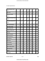
Service Maintenance
90K
Bushings - Pressure Roller
Fusing Entrance and Exit Guide
Plates
Fusing Unit Ass'y 110V/220 V
EM
Quantity
R
2
C
1 each
R
1
Remarks
Clean with water or
Preventive
Maintenance
Item
alcohol
Paper Tray Unit
90K
EM
Quantity
Paper Feed Roller
R
C
1
Clean with water
Friction Pad
R
C
1
Clean with water
Bottom Plate Pad
C
C
1
Clean with water
SM
2-3
CÓPIA NÃO CONTROLADA
NOTE
G176/G177/G176L
CÓPIA NÃO CONTROLADA
CÓPIA NÃO CONTROLADA
CÓPIA NÃO CONTROLADA
REPLACEMENT AND ADJUSTMENT
SECTION 3
Page
REPLACEMENT AND ADJUSTMENT REVISION HISTORY
Date
Added/Updated/New
None
CÓPIA NÃO CONTROLADA
CÓPIA NÃO CONTROLADA
CÓPIA NÃO CONTROLADA
CÓPIA NÃO CONTROLADA
General
3. REPLACEMENT AND ADJUSTMENT
3.1 GENERAL
3.1.1 PRECAUTIONS ON DISASSEMBLY
Always turn off the main power switch and unplug the machine before attempting
any of the procedures in this section.
Use extreme caution when removing and replacing components. The cables in the
machine are located very close to moving parts; proper routing is a must.
After components have been removed, any cables that have been displaced during the
procedure must be restored as close as possible to their original positions. Before
removing any component from the machine, note any cable routings that may be affected.
Before servicing the machine:
1.
Verify that documents are not stored in memory.
2.
Remove the print cartridge before you remove parts.
3.
Unplug the power cord.
4.
Work on a flat and clean surface.
5.
Replace with authorized components only.
6.
Do not force plastic material components.
Make sure all components are returned to their original positions.
Laser Unit
1.
Do not loosen or adjust the screws securing the LD drive board on the LD unit. Doing
so will throw the LD unit out of adjustment.
2.
Do not adjust the variable resistors on the LD unit, as these are permanently adjusted
at the factory. If replacement of the LD drive board is necessary, replace the entire LD
unit.
3.
Keep the polygon mirror and toroidal lens free of dust. Laser performance is very
sensitive to dust on these components.
4.
Do not touch the shield glass or the surface of the polygon mirror with bare hands.
5.
Do not adjust the Laser Synchronization detector on the LD unit, as these are
permanently adjusted at the factory. If the position of the Laser Synchronization
detector has changed from the factory set position, SC 322 will be shown.
SM
3-1
CÓPIA NÃO CONTROLADA
G176/G177/G176L
Replacement
and
Adjustment
CÓPIA NÃO CONTROLADA
General
Transfer Roller
1.
Never touch the surface of the transfer roller with bare hands.
2.
Be careful not to scratch the transfer roller, as the surface is easily damaged.
Fusing
1.
After installing the fusing thermistor, make sure that it is in contact with the hot roller
and that the roller can rotate freely.
2.
Be careful to avoid damage to the hot roller stripper pawls and their tension springs.
3.
Do not touch the fusing lamp and rollers with bare hands.
4.
Make sure that the fusing lamp is positioned correctly and that it does not touch the
inner surface of the hot roller.
Paper Feed
1.
Do not touch the surface of paper feed rollers.
2.
To avoid misfeeds, the side and end fences in each paper tray must be positioned
correctly so as to align with loaded paper size.
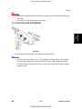
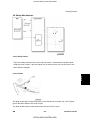
3.1.2 RELEASING PLASTIC LATCHES
Many of the parts are held in place with plastic latches. The latches break easily, so release
them carefully. To release a latch, press the hook end of the latch away from the part to
which it is latched.
G176/G177/G176L
3-2
CÓPIA NÃO CONTROLADA
SM
CÓPIA NÃO CONTROLADA
General
3.1.3 AFTER SERVICING THE MACHINE
Make sure all parts that require grounding are properly grounded.
2.
Make sure the interlock switch is functioning.
3.
Do not leave unused solder or parts inside the machine.
4.
Do not leave any tools inside the machine.
5.
Make sure all wires are properly connected and routed.
6.
Make sure wires are not jammed between parts of the machine.
Replacement
and
Adjustment
1.
SM
3-3
CÓPIA NÃO CONTROLADA
G176/G177/G176L
CÓPIA NÃO CONTROLADA
Special Tools
3.2 SPECIAL TOOLS
Part No.
Description
Q’ty
Remarks
1
B6455010
SD Card
1
Common
2
B6456700
PCMCIA Card Adapter
1
Common
3
B6456800
USB Reader/Writer
1
Common
4
VSSM9000
Digital Multimeter – FLUKE 187
1
Common
5
A0069104
Scanner Positioning Pin (4pcs/set)
1
Common
Ricoh System Information Tool
(Support Tool Ver. 2)
6
---
Basic
1
version
Mail
1
version
G176/G177/G176L
3-4
CÓPIA NÃO CONTROLADA
SM
CÓPIA NÃO CONTROLADA
Covers
3.3 COVERS
Replacement
and
Adjustment
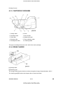
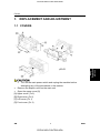
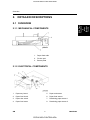
3.3.1 FRONT COVER
To open the front cover, gently push the cover inward (hooks x2).
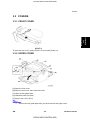
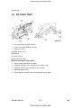
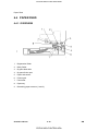
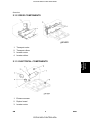
3.3.2 UPPER COVER
[A] Open the front cover.
[B] Open the rear cover, then remove the AIO.
[C] Open the exit guide plate.
[D] Operation panel (2 hooks)
[E] Upper cover (x4, x1)
SM
Remove the exit guide plate after you have removed the upper cover.
3-5
CÓPIA NÃO CONTROLADA
G176/G177/G176L
CÓPIA NÃO CONTROLADA
Covers
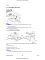
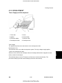
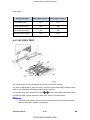
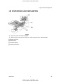
3.3.3 BY-PASS TRAY UNIT
Remove the by-pass tray unit before removing the exterior covers.
Remove the paper tray.
Remove the by-pass tray unit before removing the exterior covers.
[A] By-pass tray unit (hooks x2)
3.3.4 EXTERIOR COVERS
To remove the left or right cover, separate the machine from the optional paper tray unit
first.
[A] Left cover (x 2)
[B] Front cover (= x3, x2)
[C] Right cover (hooks x3, fan cover x1)
Pull out the standard paper tray before removing the front cover.
G176/G177/G176L
3-6
CÓPIA NÃO CONTROLADA
SM
CÓPIA NÃO CONTROLADA
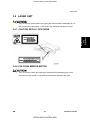
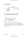
Laser Unit
3.4 LASER UNIT
Turn off the main power switch and unplug the machine before attempting any of
the procedures in this section. Laser beams can seriously damage your eyes.
Replacement
and
Adjustment
3.4.1 CAUTION DECAL LOCATIONS
3.4.2 POLYGON MIRROR MOTOR
Turn off the main switch and unplug the machine before attempting any of the
procedures in this section. Laser beams can seriously damage your eyes.
SM
3-7
CÓPIA NÃO CONTROLADA
G176/G177/G176L
CÓPIA NÃO CONTROLADA
Laser Unit
Upper cover ( See "Upper Cover")
[A] Polygon mirror cover ( x 2)
[B] Polygon mirror motor ( x 4, x 1)
Never touch the surface of the mirror with bare hands.
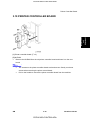
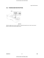
3.4.3 LASER SYNCHRONIZATION DETECTOR
Upper cover (See "Upper Cover")
By-pass tray unit (See "Bypass Tray Unit")
Exterior covers (See "Exterior Covers")
[A] Laser synchronization detector ( x1)
G176/G177/G176L
3-8
CÓPIA NÃO CONTROLADA
SM
CÓPIA NÃO CONTROLADA
Laser Unit
Replacement
and
Adjustment
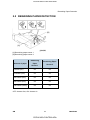
3.4.4 LASER UNIT
Upper cover (See "Upper Cover")
Exterior covers (See "Exterior Covers")
[A] Clip
[B] Laser unit ( x 4, 1 flat cable, x 2)
When reinstalling the laser unit.
Use the scanner positioning pins (P/N: A0069104) to reinstall the unit.
Set the positioning pins as shown above. Then secure the laser unit.
SM
3-9
CÓPIA NÃO CONTROLADA
G176/G177/G176L
CÓPIA NÃO CONTROLADA
Laser Unit
3.4.5 LASER DIODE UNIT
Laser Unit (See "Laser Unit")
[A] Spring
[B] LD unit holders (x 2)
[C] Loosen the screw
[D] Nut
[E] LD Unit
Do not remove the screws that secure the LD board.
Do not touch any variable resistors on the LD board.
Reinstallation:
Tighten the screw [C] until the unpainted portion of the screw
After installing the LD unit, check the test pattern for the final adjustment (see the
is not visible.
following procedure).
3.4.6 LASER BEAM PITCH ADJUSTMENT
1.
Print out the following test patterns – cross-stitch pattern and two-dot argyle pattern.
Select the test pattern with SP 2902.
After selecting a pattern, the display automatically goes to SP 5902. Use SP
5902-1 to print one test pattern.
After completing the adjustment, reset SP 2902 to ‘no specified’.
G176/G177/G176L
3-10
CÓPIA NÃO CONTROLADA
SM
CÓPIA NÃO CONTROLADA
Laser Unit
2.
Check these test patterns. If the laser beam pitch is not correct, the images are as
follows.
Cross-stitch pattern: Vertical black strips seem to appear.
Argyle pattern: The density of the diagonal lines is light or the lines have
disappeared.
3.
Adjust the LD unit holder position: Tighten or loosen the screw [C] (see the previous
page) until the printout appears as follows.
Cross-stitch pattern: The thin lines are of uniform thickness (no striping effect
should appear on the printout).
SM
Grid pattern: The diagonal lines appear clearly and are of normal density.
3-11
CÓPIA NÃO CONTROLADA
G176/G177/G176L
Replacement
and
Adjustment
CÓPIA NÃO CONTROLADA
Laser Unit
G176/G177/G176L
3-12
CÓPIA NÃO CONTROLADA
SM
CÓPIA NÃO CONTROLADA
Transfer Roller
Replacement
and
Adjustment
3.5 TRANSFER ROLLER
Remove the AIO.
[A] Transfer roller
SM
Do not touch the transfer roller surface.
3-13
CÓPIA NÃO CONTROLADA
G176/G177/G176L
CÓPIA NÃO CONTROLADA
Toner End Sensor
3.6 TONER END SENSOR
Remove the AIO.
[A] Toner end sensor (hooks x4, x 1)
G176/G177/G176L
3-14
CÓPIA NÃO CONTROLADA
SM
CÓPIA NÃO CONTROLADA
Fusing
3.7 FUSING
Allow time for the unit to cool before doing the following procedure.
Replacement
and
Adjustment
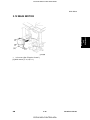
3.7.1 FUSING UNIT
[A] Rear cover
[B] Fusing unit hooks [C] (x2).
SM
Lift both hooks before attempting to remove the fusing unit from the machine.
3-15
CÓPIA NÃO CONTROLADA
G176/G177/G176L
CÓPIA NÃO CONTROLADA
Fusing
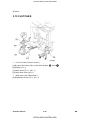
3.7.2 HOT ROLLER AND FUSING LAMP
Fusing Unit (See "Fusing Unit")
[A] Left cover ( x 1)
[B] Plate ( x 2)
[C] Upper fusing unit assembly ( x 4, Springs x2)
[D] Right cover ( x 1)
[E] Lamp holders ( x 1 each)
Remove both springs before taking apart the fusing unit assembly. The reason for
this is to relieve pressure on the unit.
When reinstalling the fusing unit assembly, install both springs last. The reason for
this is to reset the springs back to their default position.
G176/G177/G176L
3-16
CÓPIA NÃO CONTROLADA
SM
CÓPIA NÃO CONTROLADA
Replacement
and
Adjustment
Fusing
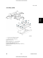
[A] Fusing Lamp ( x2)
The colored cable must be at the hot roller gear side.
[B] Guide plate (3 hooks)
[C] Hot roller strippers (1 spring each)
[D] Hot roller (2 C-rings, 1 gear, 2 bushings)
Before removing the hot roller from the unit, remove the gear and the pin first,
Use a small screwdriver to separate the guide plate from the unit.
Before installing the new hot roller, peel off 3 cm (1 inch) from both ends of the
protective sheet on the new hot roller. Be sure to remove the remaining paper
before starting the machine.
SM
3-17
CÓPIA NÃO CONTROLADA
G176/G177/G176L
CÓPIA NÃO CONTROLADA
Fusing
3.7.3 PRESSURE ROLLER
Fusing Unit (See "Fusing Unit")
Hot roller and fusing lamp (See "Hot Roller and Fusing Lamp")
[A] Pressure roller
[B] Bushing
[C] Pressure roller lever
[D] Spring
3.7.4 THERMISTOR AND THERMOSTAT
Hot roller and fusing lamp (See "Hot Roller and Fusing Lamp")
[A] Wire cover ( x 1)
[B] Grounding plate ( x 2, 1 wire)
[C] Fusing unit connector ( x 6, x1, 2 hooks)
[D] Thermistor ( x 1, x1)
[E] Thermostat ( x 1)
G176/G177/G176L
3-18
CÓPIA NÃO CONTROLADA
SM
CÓPIA NÃO CONTROLADA
Fusing
When removing the thermistor, remove the entire unit first and then separate it into
two parts.
Do not touch the thermostat with your hands.
Replacement
and
Adjustment
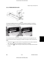
3.7.5 HOT ROLLER STRIPPERS
Hot roller and fusing lamp (See "Hot Roller and Fusing Lamp")
Two extra hot roller strippers A, B are installed for a better grip on narrow paper.
This prevents paper from curling around the hot roller. When installing the extra
hot roller strippers, insert them in the two slots using a small pair of pliers until they
snap into place.
SM
3-19
CÓPIA NÃO CONTROLADA
G176/G177/G176L
CÓPIA NÃO CONTROLADA
Paper Feed
3.8 PAPER FEED
3.8.1 PAPER FEED ROLLER
Pull out the paper tray before removing the paper feed roller.
[A] Paper feed roller
G176/G177/G176L
3-20
CÓPIA NÃO CONTROLADA
SM
CÓPIA NÃO CONTROLADA
Paper Feed
Replacement
and
Adjustment
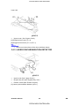
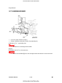
3.8.2 FRICTION PAD
Remove the paper tray unit from the machine before removing the friction pad.
[A] Friction pad (2 hooks, 1 spring)
When reinstalling the friction pad follow this order
1.
Replace the spring.
2.
Insert the right side of the friction pad first followed by the left side.
3.
Gently push the friction pad down into the slot and then pull forward very slightly.
SM
3-21
CÓPIA NÃO CONTROLADA
G176/G177/G176L
CÓPIA NÃO CONTROLADA
By-pass Tray
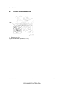
3.9 BY-PASS TRAY
Left Cover (See "Exterior Covers")
Front Cover (See "Exterior Covers")
Remove the AIO.
[A] Paper guide ( x 2)
[B] Actuator
[C] Clutch ( x1)
[D] By-pass feed roller
When reinstalling the paper guide.
1.
Set the paper guide on the bushing.
2.
Install the right part of the actuator on the paper guide.
3.
Install the left part of the actuator in the machine.
4.
Install the paper guide.
5.
Check that the actuator moves smoothly and swings freely.
G176/G177/G176L
3-22
CÓPIA NÃO CONTROLADA
SM
CÓPIA NÃO CONTROLADA
Printer Controller Board
Replacement
and
Adjustment
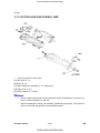
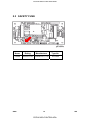
3.10 PRINTER CONTROLLER BOARD
[A] Printer controller board ( x 2)
[B] NVRAM
Remove the NVRAM from the old printer controller board and insert it on the new
board.
The screws on the printer controller board are hand screws. Gently turn these
screws when removing the printer control board.
SM
Pull on the handle to remove the printer controller board from the machine.
3-23
CÓPIA NÃO CONTROLADA
G176/G177/G176L
CÓPIA NÃO CONTROLADA
Engine Board
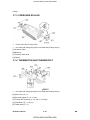
3.11 ENGINE BOARD
Left cover (See "Exterior Covers")
Printer controller board (See "Printer Controller Board")
[A] Bracket ( x7, 1 grounding wire)
Be careful not to damage the flat cable.
[B] Clip
[C] Engine board ( x4, all connectors)
Remove the NVRAM [D] from the old engine board and insert it on the new board.
G176/G177/G176L
3-24
CÓPIA NÃO CONTROLADA
SM
CÓPIA NÃO CONTROLADA
Main Motor
Replacement
and
Adjustment
3.12 MAIN MOTOR
Left cover (See "Exterior Covers")
[A] Main motor ( x4, x 1)
SM
3-25
CÓPIA NÃO CONTROLADA
G176/G177/G176L
CÓPIA NÃO CONTROLADA
Clutches
3.13 CLUTCHES
Left cover (See "Exterior Covers")
[A] By-pass feed clutch (x 1) with clutch bracket
, holder
[B] Stopper ( x 1)
[C] Relay clutch ( x 1, x 1)
[D] Paper feed clutch ( x 1)
Main motor (See "Main Motor")
[E] Registration clutch (x 1, x 1)
G176/G177/G176L
3-26
CÓPIA NÃO CONTROLADA
SM
CÓPIA NÃO CONTROLADA
PSU, HVPS
Replacement
and
Adjustment
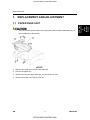
3.14 PSU, HVPS
Left cover. See "Exterior Covers"
Fusing unit. See "Fusing Unit"
[A] PSU cover ( x 2)
[B] PSU assembly ( x 7, all connectors)
[C] High voltage supply board ( x 4)
[D] 230-volt machine only: Choke coil ( x 2 x 1)
[E] PSU (x 5)
SM
3-27
CÓPIA NÃO CONTROLADA
G176/G177/G176L
CÓPIA NÃO CONTROLADA
Cooling Fan
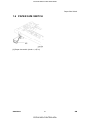
3.15 COOLING FAN
Right cover (See "Exterior Covers")
[A] Cooling fan (x 2, x1)
The cooling fan must be reinstalled in its original position. Do not reinstall the
cooling fan opposite to the original position.
G176/G177/G176L
3-28
CÓPIA NÃO CONTROLADA
SM
CÓPIA NÃO CONTROLADA
TROUBLESHOOTING
SECTION 4
Page
17
6 ~ 17
TROUBLESHOOTING (SC CODES) REVISION HISTORY
Date
Added/Updated/New
07/31/2009
SC998
10/27/2009
Added & deleted SC’s
CÓPIA NÃO CONTROLADA
CÓPIA NÃO CONTROLADA
CÓPIA NÃO CONTROLADA
CÓPIA NÃO CONTROLADA
Service Call Conditions
4. TROUBLESHOOTING
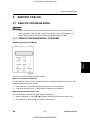
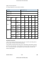
4.1 SERVICE CALL CONDITIONS
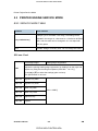
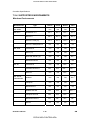
4.1.1 SUMMARY
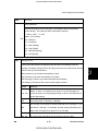
There are 4 levels of service call conditions
Definition
Reset Procedure
Fusing unit SCs shown on the
A
operation panel. The machine is
disabled. The user cannot reset the
SC.
1.
Do SP5810 and press [#Enter].
2.
When "execute" is displayed, press
[#Enter] again.
3.
Press [Escape].
4.
Turn the machine power off/on.
These SCs disable only the features
that use the defective item. The
B
user does not see these SCs in
Set the main power switch to “off” then
usual conditions. But, they are
to “on”.
shown on the operation panel when
the defective feature is used.
SCs that are not shown on the
C
operation panel. They are recorded
Recorded only.
internally.
These SCs are shown on the
operation panel. To reset these
D
SCs, turn the operation switch or
Set the operation switch or the main
main power switch off and on.
power switch to “off” then to “on”.
These SCs are shown again if the
error occurs again.
SM
4-1
CÓPIA NÃO CONTROLADA
G176/G177/G176L
Troubleshooting
Level
CÓPIA NÃO CONTROLADA
Service Call Conditions
If the problem is with electrical circuit boards, disconnect the connectors first. Then
reconnect the connectors before you replace the PCBs.
If the problem is with a motor lock, first examine the mechanical load. Then
replace motors or sensors.
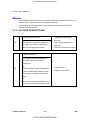
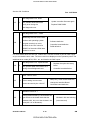
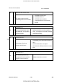
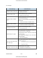
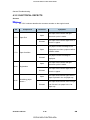
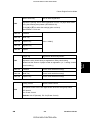
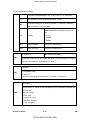
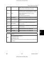
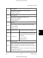
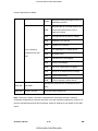
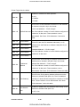
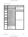
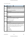
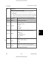
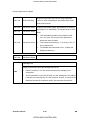
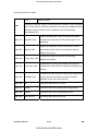
4.1.2 SC CODE DESCRIPTIONS
Charge roller current leak
Cartridge (charge roller)
defective
302
B
The PWM duty output exceeded 60%
for longer than 200 ms., indicating a
leak in the charge roller current.
High voltage supply board
defective
Defective cartridge connection
Polygon motor
Polygon motor cable
Polygon motor error
The polygon motor did not enter the
lock state within 20 sec. after it
switched on.
-or320
B
Once the polygon motor was detected
in the lock state after started to rotate,
within 0.6 sec. it entered the unlock
state..
-orAfter the polygon motor switched off, it
did not enter unlock state within 20 sec.
G176/G177/G176L
4-2
CÓPIA NÃO CONTROLADA
SM
CÓPIA NÃO CONTROLADA
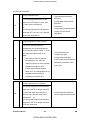
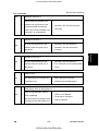
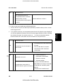
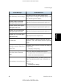
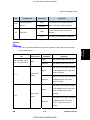
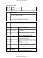
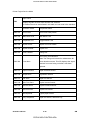
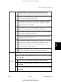
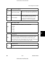
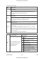
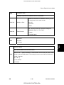
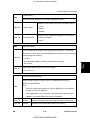
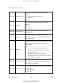
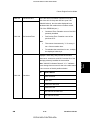
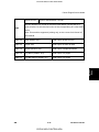
Service Call Conditions
1st beam laser synchronization error
Laser synchronization
detector board out of position
322
B
Laser synchronization
With all doors closed the polygon motor
detector board or cable
is locked and not rotating, or the laser
defective
synchronization detector could not
detect 1st beam laser detection signal
within 5 ms..
Laser synchronization mirror
out of position
LD unit defective
Engine board defective
LD unit defective
Laser synchronization
LD drive current exceeded
B
The LD driver detected an error for 500
Troubleshooting
323
ms.
2nd beam laser synchronization error
With all doors closed the polygon motor
326
B
is locked and not rotating, or the laser
synchronization detector could not
detect 2nd beam laser detection signal
detector board out of position
LD unit defective
Engine board defective
High voltage supply board
within 500 ms.
Development bias leak
391
B
A development bias leak signal was
detected
for 200 ms.
Main motor error
500
B
A main motor lock signal was not
detected within 700 ms after the main
defective
Defective cartridge connection
Main motor defective
Mechanical overload on the
drive mechanism
motor started to rotate.
SM
4-3
CÓPIA NÃO CONTROLADA
G176/G177/G176L
CÓPIA NÃO CONTROLADA
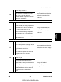
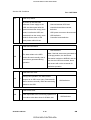
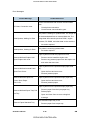
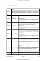
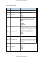
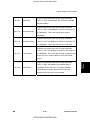
Service Call Conditions
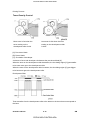
Fusing thermistor error
The fusing temperature did not rise
higher than 20oC within 11 sec. after
541
A
the main motor switched off.
-orThe fusing temperature was detected
lower than 0oC for over 1 sec. after the
Thermistor disconnected,
defective
Fusing lamp disconnected,
defective
Fuse blown
Power supply board defective
Fusing unit connected
improperly
power relay switched on.
Fusing temperature warm-up error
Just before reaching warm-up
temperature, the fusing temperature
did not rise above 80oC within 17.5 sec.
after the power relay switched on.
Note:
542
A
The machine starts to test the
temperature 2 sec. after the
machine powers on if the machine
Thermistor defective
Fusing lamp open
Fusing thermostat open
Power supply board Defective
Defective connection of the
fusing unit
temperature is above 45oC.
If the machine temperature is
below 45oC, the temperature is not
sampled until the machine
temperature reaches 45oC.
Fusing overheat error – software
The fusing temperature was detected
higher than 245oC for longer than 200
543
A
ms while the main motor was on or
Fusing thermistor defective
within 60 sec. after the main motor
Power supply board defective
switched off.
-or-
The fusing temperature was detected
higher than 235oC for longer than 200
ms at any other time.
G176/G177/G176L
4-4
CÓPIA NÃO CONTROLADA
SM
CÓPIA NÃO CONTROLADA
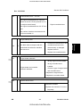
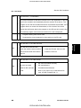
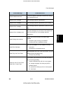
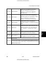
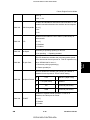
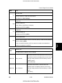
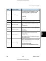
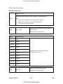
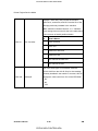
Service Call Conditions
Fusing lamp remains on
545
A
Fusing thermistor defective
The fusing lamp remained on longer
Power supply board defective
than 12 sec. after the fusing unit
Defective connection of the
reached optimum temperature and the
fusing unit
main motor switched off.
Unstable fusing temperature
During standby, the fusing temperature
546
A
went below 60 °C twice or went above
Fusing thermistor defective
60 °C three times within 500 ms.
Power supply board defective
Defective connection of the
A 60°C increase in fusing temperature
fusing unit
Troubleshooting
was detected at five 1-sec. intervals
within 60 to 90 sec. before reaching
fusing temperature.
Zero cross signal error
Zero cross signals of wavelength 50-60
547
B
Hz were not detected within 5 sec after
the fusing relay switched on.
Power supply board defective
Defective mains power supply
condition
-orZero cross interrupts did not issue at
the prescribed 1 sec. intervals.
559
A
Fusing unit jam
Three consecutive paper lag jams
(paper failed to arrive) were detected in
Fusing unit installed
the fusing unit. -or-
incorrectly
During printing of the 1st side during
Fusing unit defective
duplexing, the paper did not arrive at
the duplex entrance sensor three
times.
SM
4-5
CÓPIA NÃO CONTROLADA
G176/G177/G176L
CÓPIA NÃO CONTROLADA
Service Call Conditions
Rev. 10/27/2009
Note: SP1913 determines whether SC559 is issued. The default is off.
SC559 is not issued after three consecutive jams in the paper unit. If
SP1913 is set to on, turning the machine power off/on does not reset the jam
counter.
Fan motor error
590
B
Fan motor disconnected,
The machine detected an error in the
defective
fusing unit fan or the PSU fan. Either
or both fan motors started to rotate
Fan motor harness loose,
broken, defective
within 10 sec. after power on.
Communication error - duplex unit
The engine board could not
communicate with the duplex unit.
610
B
Defective connection between
engine board and duplex unit
(The duplex unit did not respond
Engine board defective
within 1 sec. to a status request.)
Duplex control board defective
Note: This SC is logged, not
displayed.
Communication error – GAVD I2C
The engine board detected an unknown
device on the I2C I/F bus (internal bus on
650
B
the engine control board).
Engine board defective
The engine board detected an I2C I/F bus
error.
The number of devices connected to the
I2C bus exceeded 12.
G176/G177/G176L
4-6
CÓPIA NÃO CONTROLADA
SM
CÓPIA NÃO CONTROLADA
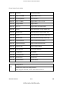
Service Call Conditions
Rev. 10/27/2009
651
Communication error – FCI I2C
The engine board detected an unknown
device on the I2C I/F bus (internal bus on
B
the engine control board).
Engine board defective
The engine board detected an I2C I/F bus
error.
The number of devices connected to the
I2C bus exceeded 12.
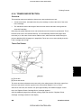
Engine startup error
670
D
The BCU failed to respond with the
controller board are loose,
prescribed time when the machine
disconnected, or damaged
was turned on.
⇒
671
Connections between BCU and
Replace the BCU
Replace the controller board
Wrong engine board installed.
Wrong controller board
Engine board mismatch
installed.
Engine board and controller
mismatch detected.
Check the type of engine board
and controller board.
1. Replace the engine board.
2. Replace the controller board.
⇒
818
System timeout error
• Defective controller
• Replace the controller if it occurs
frequently.
SM
4-7
CÓPIA NÃO CONTROLADA
G176/G177/G176L
Troubleshooting
CÓPIA NÃO CONTROLADA
Service Call Conditions
819
Rev. 10/27/2009
Fatal kernel error
Due to a control error, a RAM
overflow occurred during system
processing. One of the following
messages was displayed on the
C
operation panel.
System program defective
Controller board defective
Optional board defective
Replace controller firmware
0x696e
init died
0x766d
vm_pageout: VM is full
4361
Cache Error
Other
For more details about this SC code error, execute SP5990 to print an SMC report so you
can read the error code. The error code is not displayed on the operation panel.
Self-Diagnostic Error: CPU
820
D
defective
The central processing unit returned an error
during the self-diagnostic test.
Controller board
Software defective
Self-diagnostic error 2: ASIC
The ASIC provides the central point
for the control of bus arbitration for
821
D
CPU access, for option bus and
SDRAM access, for SDRAM refresh,
ASIC (controller board
defective)
and for management of the internal
bus gate.
For more details about this SC code error, execute SP5990 to print an SMC report so you
can read the error code. The error code is not displayed on the operation panel.
G176/G177/G176L
4-8
CÓPIA NÃO CONTROLADA
SM
CÓPIA NÃO CONTROLADA
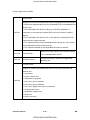
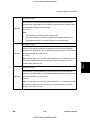
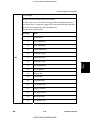
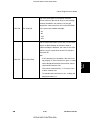
Service Call Conditions
Rev. 10/27/2009
822
B
Self-diagnostic error 3: HDD
Check performed when HDD is
installed:
3003
HDD device busy for over
HDD defective
31 s.
HDD harness
After a diagnostic command is set for
disconnected,
Sthe HDD, but the device remains
defective
busy for over
Controller board
defective
6 s.
A diagnostic command is issued to the
HDD device but the result is an erro
No response to the self-diagnostic
HDD defective
Troubleshooting
3004
command from the ASIC to the HDDs
Self-diagnostic Error: NIC
823
B
The network interface board
Network interface board defective
returned an error during the
Controller board defective
NVRAM defective
Controller board defective
NVRAM backup battery exhausted
NVRAM socket damaged
Make sure NVRAM is seated
self-diagnostic test.
Self-diagnostic error 4: NVRAM
824
D
NVRAM device does not exist,
NVRAM device is damaged,
NVRAM socket damaged
Self-diagnostic Error:
NVRAM/Optional NVRAM
826
D
correctly in its socket
The NVRAM or optional NVRAM
returned an error during the
Replace the NVRAM on the
controller board
self-diagnostic test.
SM
4-9
CÓPIA NÃO CONTROLADA
G176/G177/G176L
CÓPIA NÃO CONTROLADA
Service Call Conditions
Rev. 10/27/2009
Self-diagnostic Error: RAM
827
D
The resident RAM returned a
Update controller firmware again
verify error during the
Replace RAM DIMM
self-diagnostic test.
Self-diagnostic error 7: ROM
Measuring the CRC for the boot
monitor and operating system
828
D
program results in an error.
A check of the CRC value for
ROMFS of the entire ROM area
Software defective
Controller board defective
ROM defective
results in an error.
For more details about this SC 833, SC834 error, execute SP5990 to print an SMC report
so you can read the error code. The error code is not displayed on the operation panel. The
additional error codes (0F30, 0F31, etc. are listed in the SMC report.
Self-diagnostic Error: Optional RAM
829
B
board
The optional RAM returned an error
during the self-diagnostic test.
Replace the optional memory
Controller board defective
IEEE 1394 I/F error
851
B
Driver setting incorrect and
cannot be used by the 1394 I/F.
NIB (PHY), LINK module defective;
change the Interface Board
Controller board defective
Wireless LAN Error 1
During machine start-up, the machine can
853
B
get access to the board that holds the
wireless LAN, but not to the wireless LAN
Wireless LAN card missing
(was removed)
card (802.11b or Bluetooth).
G176/G177/G176L
4-10
CÓPIA NÃO CONTROLADA
SM
CÓPIA NÃO CONTROLADA
Service Call Conditions
Rev. 10/27/2009
854
Wireless LAN Error 2
During machine operation, the
B
machine can get access to the
board that holds the wireless
Wireless LAN card missing (was
removed)
LAN, but not to the wireless LAN
card (802.11b or Bluetooth).
Wireless LAN error 3
B
An error was detected on the
Wireless LAN card defective
wireless LAN card (802.11b or
Wireless LAN card connection
incorrect
Bluetooth).
Wireless LAN error 4
856
B
An error was detected on the
Wireless LAN card defective
wireless LAN card (802.11b or
PCI connector (to the mother board)
loose
Bluetooth).
USB I/F Error
857
B
The USB driver is not stable and
Bad USB card connection
caused an error.
Replace the controller board
HDD startup error at main power on
HDD is connected but a driver
860
B
error is detected.
The driver does not respond with
the status of the HDD within 30 s.
SM
HDD is not initialized
Level data is corrupted
HDD is defective
4-11
CÓPIA NÃO CONTROLADA
G176/G177/G176L
Troubleshooting
855
CÓPIA NÃO CONTROLADA
Service Call Conditions
861
Rev. 10/27/2009
HDD re-try failure
At power on the HDD was
detected. Power supply to the
D
Harness between HDD and
HDD was interrupted after the
controller board disconnected,
system entered the energy save
defective
mode, but after the HDD was
HDD power connector disconnected
awakened from the energy save
HDD defective
mode it did not return to the
Controller board defective
HDD defective
ready status within 30 sec.
HDD data read failure
Note: If the bad sectors are generated at
The data written to the HDD
863
D
cannot be read normally, due to
bad sectors generated during
operation.
the image partition, the bad sector
information is written to NVRAM, and the
next time the HDD is accessed, these
bad sectors will not be accessed for
read/write operation.
HDD data CRC error
During HDD operation, the HDD cannot
864
D
respond to an CRC error query. Data transfer
did not execute normally while data was being
HDD defective
written to the HDD.
HDD access error
865
D
HDD responded to an error during operation for
a condition other than those for SC863, 864.
G176/G177/G176L
4-12
CÓPIA NÃO CONTROLADA
HDD defective.
SM
CÓPIA NÃO CONTROLADA
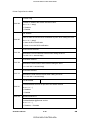
Service Call Conditions
Rev. 10/27/2009
866
SD card error 1: Confirmation
The machine detects an electronic license error in the application on the SD
card in the controller slot immediately after the machine is turned on. The
B
program on the SD card contains electronic confirmation license data. If the
program does not contain this license data, or if the result of the check
shows that the license data in the program on the SD card is incorrect, then
the checked program cannot execute and this SC code is displayed.
Program missing from the SD card
Download the correct program for the machine to the SD card
The SD card in the boot slot
867
D
when the machine was turned on
Insert the SD card, then turn the
was removed while the machine
machine off and on.
was on.
SD card error 3: SC card access
868
D
SD card not inserted correctly
An error occurred
SD card defective
while an SD card was
Controller board defective
used.
Note: If you want to try to reformat the SC
card, use SD Formatter Ver 1.1.
SM
4-13
CÓPIA NÃO CONTROLADA
G176/G177/G176L
Troubleshooting
SD card error 2: SD card removed
CÓPIA NÃO CONTROLADA
Service Call Conditions
870
Rev. 10/27/2009
Address book data error
B
Address book data on the hard disk
HDD defective.
was detected as abnormal when it
Initialize the HDD with
was accessed from either the
SP5832. If this does not solve
operation panel or the network. The
the problem, replace the HDD
address book data cannot be read
and initialize with SP5832.
from the HDD or SD card where it is
Note: If you turn off the machine
stored, or the data read from the
while the HDD is being accessed,
media is defective.
this can damage the HDD.
HDD mail receive data error
The machine detected that the
HDD was not operating correctly
872
B
HDD defective.
Initialize the HDD with SP5832. If
this does not solve the problem,
at power on.
replace the HDD and initialize with
The machine detected that the
HDD was not operating correctly
(could neither read nor write)
while processing incoming email
SP5832.
Note: If you turn off the machine while
the HDD is being accessed, this can
damage the HDD.
HDD mail send data error
An error was detected on the
873
B
HDD defective.
Initialize the HDD with SP5832. If
this does not solve the problem,
HDD immediately after the
machine was turned on, or power
was turned off while the machine
used the HDD.
replace the HDD and initialize with
SP5832.
Note: If you turn off the machine while
the HDD is being accessed, this can
damage the HDD.
G176/G177/G176L
4-14
CÓPIA NÃO CONTROLADA
SM
CÓPIA NÃO CONTROLADA
Service Call Conditions
Rev. 10/27/2009
874
Delete All error 1: HDD
D
A data error was detected for the
Turn the main switch off/on and try
HDD/NVRAM after the Delete All
the operation again.
option was used.
Install the Data Overwrite Security
Note: The source of this error is
Unit again. For more, see section “1.
the Data Overwrite Security Unit
Installation”.
B660 running from an SD card.
HDD defective
Turn the main switch off/on and try
Delete All error 2: Data area
An error occurred while the
D
HDD.
the operation again.
Note: The source of this error is
the Data Overwrite Security Unit
B660 running from an SD card.
876
D
Log data abnormal
An error was detected in the
handling of the log data at power
on or during machine operation.
This can be caused by switching
Software error. Update the firmware
NVRAM defective
HDD defective
Defective SD card.
SD card not installed
the machine off while it is
operating.
877
⇒
HDD Data Overwrite Security SD
card error
The 'all delete' function cannot
1. Replace the NVRAM and then install
be executed but the Data
the new SD card.
Overwrite Security Unit is
2. Check and reinstall the SD card.
installed and activated.
SM
4-15
CÓPIA NÃO CONTROLADA
G176/G177/G176L
Troubleshooting
machine deleted data from the
875
CÓPIA NÃO CONTROLADA
Service Call Conditions
900
Rev. 10/27/2009
Electrical total counter error
D
The total counter contains
something that is not a number.
NVRAM incorrect type
NVRAM defective
NVRAM data scrambled
Unexpected error from external
source
Printer error 1
920
B
An internal application error
off/on, or change the controller firmware
was detected and operation
cannot continue.
⇒
921
Software defective; turn the machine
Insufficient memory
A necessary font is not found in the SD
Printer font error
A necessary font is not
found in the SD card.
card.
The SD card data is corrupted.
Check that the SD card has the correct
data.
Software error 1
990
D
The software performs an
unexpected function and the
Software defective, re-boot*1
program cannot continue.
G176/G177/G176L
4-16
CÓPIA NÃO CONTROLADA
SM
CÓPIA NÃO CONTROLADA
Service Call Conditions
Rev. 10/27/2009
991
Software error 2
The software performs an
C
unexpected function. However,
Software defective, re-boot*1
unlike SC990, recovery
processing allows the program to
continue.
*1: In order to get more details about SC990 and SC991:
1.
Execute SP7403 or print an SMC Report (SP5990) to read the history of the 10 most
recent logged errors.
2.
If you press the zero key on the operation panel with the SP selection menu displayed,
the software file name, line number, and so on.
1) is the recommended method,
because another SC could write over the information for the previous SC.
Printer font error
992
A necessary font is not found in
the SD card.
A necessary font is not found in the
SD card.
The SD card data is corrupted.
Check that the SD card stores
correct data.
⇒
998
Loose connection of
RAM-DIMM, ROM-DIMM
Application start error
Defective controller
Software problem
1. Check if the RAM-DIMM and
No applications start within 60
seconds after the power is turned on.
ROM-DIMM are correctly connected.
2. Reinstall the controller system
firmware.
3. Replace the controller board.
SM
4-17
CÓPIA NÃO CONTROLADA
G176/G177/G176L
Troubleshooting
you will see detailed information about the recently logged SC990 or SC991, including
CÓPIA NÃO CONTROLADA
Error Messages
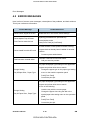
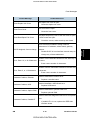
4.2 ERROR MESSAGES
Here is a list of common error messages, a description of the problems, and their solutions.
This is just a reference information.
1st/2nd Message
Problem/Solution
Cannot check, Signal in Ad hoc
Cannot duplex Tray #/ Press
Form Feed or reset the Job
Disable Ad hoc in the Comm. Mode settings.
Duplexing prohibited from specified tray.
Cancel duplex mode
Press [Form Feed] or [Job Reset].
SD card contains a DOS (Data Overwrite Security)
Cannot install from this SD card
program that has already been installed for another
machine.
Certificate auto renewal failed
Contact system administrator.
Automatic certificate renewal has failed.
Call your service provider.
The paper size/paper type settings in the application
program and printer driver do not match.
Change Setting
Change the paper type on the paper type setting
menu on the machine operation panel
Tray #/Paper Size:, Paper Type:
Push [Form Feed]
Cancel the print job.
The paper size/paper type settings in the application
program and printer driver do not match.
Do one of the following:
Change Setting
Tray #/ Paper Size:, Paper Type:
Load the tray with the correct paper
Change the paper size using the dial or the
special paper size setting menu on the operation
panel.
G176/G177/G176L
Push [Form Feed]
Cancel the print job.
4-18
CÓPIA NÃO CONTROLADA
SM
CÓPIA NÃO CONTROLADA
Error Messages
1st/2nd Message
Problem/Solution
The duplex unit cover is open.
Close Duplex Unit Cover
Close the duplex unit cover.
The front cover is open.
Close Front Cover
Close the front cover.
The paper output tray cover or the rear cover is open,
Close Rear/Paper Exit Cover
or both covers are open.
Check the covers, make sure they are closed.
DHCP has been enabled to assign network
addresses of: IP address, subnet mask, gateway
address.
Disable DHCP in host interface network setup to
change any of these addresses.
Number of hex characters entered for the WEP key is
Error: Enter 10, or 26 Characters
incorrect.
Enter correct number of characters.
Number of ASCII characters entered for the WEP key
Error: Enter 5, or 13 Characters
is incorrect.
Hardware Problem, Ethernet
Enter correct number of characters.
Machine detected an Ethernet error.
Replace controller board.
Machine identified a HDD Board error.
Hardware Problem, HDD
Hardware Problem, Option RAM
Replace HDD board.
Machine detected an optional RAM error.
Replace optional RAM.
Machine failed self-diagnostic test due to a loop back
Hardware Problem, Parallel I/F
error.
If parallel I/F is in use, replace the IEEE1284
interface board.
SM
4-19
CÓPIA NÃO CONTROLADA
G176/G177/G176L
Troubleshooting
DHCP assigned, Cannot change
CÓPIA NÃO CONTROLADA
Error Messages
1st/2nd Message
Problem/Solution
Hardware Problem, Printer Font
Problem with machine font file.
Replace print module.
Machine detected a USB I/F board error.
Hardware Problem, USB
Replace the USB I/F board.
Access to the IEEE 802.11b board was possible, but
Hardware Problem, Wireless
Board
an error has been detected.
Machine can access IEEE802.11b board but an error
was detected.
Confirm that the board is installed correctly.
Hardware Problem, Wireless
Machine failed to access IEEE 802.11b board.
Card
Confirm that the board is installed correctly.
Machine has received spurious data.
Invalid Data, Power Off On
Turn the printer off/on.
The invalid password was entered and Locked Print
or Saved File Print is not applicable.
Invalid password entered, Locked Print or Saved File
Print cannot apply.
Invalid Password, Try again
Printer displays this message for 4 sec., then returns
to previous display.
Enter correct password.
Size of paper selected does not match size selected
Load Correct Size Paper/ Paper
Size:, Paper Type:
Use the dial to select the correct paper size.
Press [Form Feed].
-or-
Load Paper: Tray# or Form Feed
G176/G177/G176L
with dial on paper tray.
The specified tray is out of paper.
Load paper in the specified tray.
4-20
CÓPIA NÃO CONTROLADA
SM
CÓPIA NÃO CONTROLADA
Error Messages
1st/2nd Message
Problem/Solution
The operation panel has been digitally locked,
Menu Protected, Cannot change
settings cannot be changed. Message displays for 5
sec., returns to previous display.
size/ Open Duplex Unit cover
Misfeed: Internal, Check paper
size/ Open Front Cover
Misfeed: Ppr, Exit Check paper
size/ Open Paper Exit Cover
Misfeed: Ppr. Tray, Check paper
size/ Pull out Tray
Paper fed from bypass tray jammed in duplex unit.
Paper fed from bypass tray jammed in duplex unit.
Paper fed from bypass tray jammed in duplex unit.
Paper is jammed in the duplex unit.
No files available for deleting or printing. This error
No Files exist
displays for 3 sec., then machine returns to previous
display.
Press # to continue/ Paper Size:,
Paper Type:
Requested paper size does not match dial setting on
the paper tray.
Proxy User Name, Password
error
Press [#] to start printing.
Proxy user name and password are incorrect.
Change current user name and password to the
correct user name and password.
1) Proxy address port No. is invalid, 2) proxy is not
active, 3) invalid center URL is set, 4) center is not
Proxy setting or connection error
active, 5)
proxy is not set.
SM
Check all proxy settings.
4-21
CÓPIA NÃO CONTROLADA
G176/G177/G176L
Troubleshooting
Misfeed: Duplex Check paper
CÓPIA NÃO CONTROLADA
Error Messages
1st/2nd Message
Problem/Solution
Cannot communicate with remote communication
gate.
RC Gate, Connection error
Check printer connection.
Check remote communication gate.
The printer is waiting for updated data. The image file
will be downloaded from an Internet Web site. The
ROM Update, Waiting for Data
image data will overwrite previous ROM , engine
firmware, PS DIMM, and other data on the machine.
ROM Update:, Waiting for Data
No action required.
The printer is receiving updated data.
No action required.
Paper is jammed under the paper exit cover.
Remove Misfeed Duplex Unit/
Remove and re-install the duplex unit.
Open Duplex Unit cover
Remove any jammed paper from the duplex unit
and under the rear cover.
Paper is jammed in the specified input paper feed
Remove Misfeed Internal Path/
tray.
Open Front Cover
Open the front and rear cover.
Remove jammed paper.
Remove Misfeed Paper Exit
Paper is jammed in the specified input paper tray.
Cover/ Open Paper
Open the front and rear cover
Exit Cover
Remove jammed paper.
Paper is jammed in the specified input paper tray.
Remove Misfeed Paper Tray/ Pull
out Tray
Remove paper from the input paper tray.
Reload paper.
Open and close front cover to extinguish
message.
Remove Paper Standard Tray
G176/G177/G176L
The standard output tray is full.
Remove paper from output tray.
4-22
CÓPIA NÃO CONTROLADA
SM
CÓPIA NÃO CONTROLADA
Error Messages
1st/2nd Message
Problem/Solution
It is time to replace: feed roller, transfer unit, fusing
Replace Maintenance Kit
unit, development unit.
Replace Print Cartridge
Print cartridge requires replacement.
Replace Print Cartridge
Print cartridge requires replacement (out of toner).
Print cartridge requires replacement (used toner tank
Replace Print Cartridge
full).
The print cartridge is out of toner or has reached the
Replace Print Cartridge soon
end of its service life. Print cartridge requires
Fusing unit not set correctly, or incorrect type
installed.
Reset Fusing Unit correctly
Check the type of fusing unit installed.
Confirm that unit is installed correctly.
AIO unit not installed or is not installed correctly.
Reset Print Cartridge
Insert AIO.
Check that it is inserted properly.
Specified paper input tray is not set correctly. (Current
Reset Tray # or Form Feed
resident printer languages only).
Set input tray correctly.
Actual paper type and size do not match the paper
tray size and type setting.
Reset the Job or Form Feed/
Paper Size:, Paper Type:
SM
Load the indicated tray with the correct paper.
Or, change the paper size using tray dial or
operation panel.
Or, push [Form Feed] to print on current paper.
Or, cancel job.
4-23
CÓPIA NÃO CONTROLADA
G176/G177/G176L
Troubleshooting
replacement.
CÓPIA NÃO CONTROLADA
Error Messages
1st/2nd Message
Problem/Solution
Authentication from the SD card failed.
SD authentication failed
SD card not set, Contact admin.
Turn the machine off/on.
The SD card for DOS is not set.
This message confirms that no ID has been entered.
SSID not entered
Enter correct ID
Supply order
Call for supply order has failed.
failed.
Update Mode Err, Power Off On
G176/G177/G176L
Confirm the setting of @Remote.
The printer has failed to restart the update.
Turn the machine off/on.
4-24
CÓPIA NÃO CONTROLADA
SM
CÓPIA NÃO CONTROLADA
General Troubleshooting
4.3 GENERAL TROUBLESHOOTING
4.3.1 IMAGE ADJUSTMENT
Registration Adjustment
The registration is adjusted in the user mode (“Maintenance-Registration”). For details, see
the Printer Reference operation manual.
Troubleshooting
Parallelogram Image Adjustment
Do the following procedure if a parallelogram is printed while adjusting the printing
registration using a trimming pattern.
Use the scanner positioning pin (P/N: A0069104) for this adjustment.
1.
Remove the upper cover (See "Upper Cover")
2.
Put a positioning pin in one of the holes
3.
Loosen four screws and move the laser unit.
4.
Tighten the laser unit.
5.
Print the trimming area pattern to check the image. If it is still the same, repeat steps 3
to 5.
SM
4-25
CÓPIA NÃO CONTROLADA
G176/G177/G176L
CÓPIA NÃO CONTROLADA
General Troubleshooting
4.3.2 ELECTRICAL DEFECTS
Sensors
CN
The "CN" numbers describe the connector number on the engine board.
Component
Condition
Open
17-5
Paper Exit
Shorted
Symptom
The Paper Jam indicator will light
whenever a print is made.
The Paper Jam indicator lights even if
there is no paper.
The paper overflow message is not
Open
17-8
condition exists.
Paper Overflow
Shorted
Open
6-A2
Registration
Shorted
Open
6-A5
displayed even when a paper overflow
Remaining paper
The paper overflow message is
displayed.
The Paper Jam indicator will light
whenever a print is made.
The Paper Jam indicator lights even if
there is no paper.
The Paper End indicator lights even if
paper is placed in the 1st paper tray.
The Paper End indicator does not light
sensor 1
Shorted
even if there is no paper in the 1st
paper tray.
G176/G177/G176L
4-26
CÓPIA NÃO CONTROLADA
SM
CÓPIA NÃO CONTROLADA
General Troubleshooting
CN
6-A8
4-3
Component
Condition
Open
Remaining paper
sensor 2
Shorted
High
Toner End
Low
Symptom
The machine cannot determine the
paper near-end condition properly.
Toner near-end (toner end) is not
detected.
The add toner message is displayed.
Switches
The "CN" numbers describe the connector number on the engine board (except
for the main switch).
CN
103-1.3 (PSU 120V)
101-1.2 (PSU 230V)
Component
Main
Condition
Symptom
Open
The machine does not turn on.
Shorted
The machine does not turn off.
The Front Cover Open message
Open
11-1
is not displayed even if the front
cover is opened.
Front Cover
Safety
The Front Cover Open message
Shorted
is displayed even if the front
cover is closed.
The Rear Cover Open message
Open
18-3
is not displayed even if the rear
cover or paper exit cover is
opened.
Rear Cover
Safety
The Rear Cover Open message
Shorted
is displayed even if the rear
cover or paper exit cover is
closed.
SM
4-27
CÓPIA NÃO CONTROLADA
G176/G177/G176L
Troubleshooting
CÓPIA NÃO CONTROLADA
General Troubleshooting
Fuses
North America
Fuse
Current
Voltage
FU1
15.0 A
AC 100V/120V
FU2
5.0 A
AC 100V/120V
FU3
4.0 A
DC 5V
FU4
4.0 A
DC 5V
Fuse
Current
Voltage
FU1
6.3 A
AC 220V-240V
FU2
3.15 A
AC 220V-240V
FU3
4.0 A
DC 5V
FU4
4.0 A
DC 5V
Europe
G176/G177/G176L
4-28
CÓPIA NÃO CONTROLADA
SM
CÓPIA NÃO CONTROLADA
General Troubleshooting
4.3.3 SKEW ADJUSTMENT
Troubleshooting
Follow the instructions in this flowchart to correct image skew.
4.3.4 STREAKS IN THE SUB SCAN DIRECTION
If you see streaks or lines at a regular interval in the sub scan direction:
1.
Measure the width of the interval between the streaks.
2.
Identify the component in the table below that is causing the problem (based on the
size of the measured interval), then inspect that component.
Interval Width (approx.)
SM
Check:
94 mm
OPC Drum (diameter 30 mm)
50 mm
Transfer Roller (diameter 16 mm)
105 mm
Fusing Roller (diameter 33 mm)
100 mm
Pressure Roller(diameter 32 mm)
4-29
CÓPIA NÃO CONTROLADA
G176/G177/G176L
CÓPIA NÃO CONTROLADA
General Troubleshooting
4.3.5 MISCELLANEOUS PROBLEMS
Here is a summary of some problems, what causes them, and how they can be solved.
Problem
Probable Cause/Solution
Black spots at approximately 94
AIO is defective, transfer roller is dirty.
mm intervals.
Replace AIO
Clean the transfer roller
Spurious noise during printing
Relay clutch defective.
Replace relay clutch
Vertical positioning of printed
Registration clutch defective
image is not consistent (sub scan
Replace registration clutch
direction)
Multiple vertical stripes appear in
NIC defective
areas of black coverage
Entire page appears gray, text
Synchronization defective.
appears light and enlarged
Frequent paper jams, or message
Registration sensor defective, registration sensor
prompts to load correct paper size
actuator defective. (High usage can foul the actuator
and type.
with paper dust.)
HDD unit not recognized
Replace main (engine) board
Replace registration sensor
Replace registration sensor actuator
The HDD unit of another machine cannot be used.
G176/G177/G176L
Replace NIC
Replace the HDD unit with the new HDD.
4-30
CÓPIA NÃO CONTROLADA
SM
CÓPIA NÃO CONTROLADA
SERVICE TABLES
SECTION 5
Page
SERVICE TABLES (SP MODES) REVISION HISTORY
Date
Added/Updated/New
65
01/02/2008
SP7931-005
78
12/12/2008
Removed SP8781
CÓPIA NÃO CONTROLADA
CÓPIA NÃO CONTROLADA
CÓPIA NÃO CONTROLADA
CÓPIA NÃO CONTROLADA
Service Program Mode
5. SERVICE TABLES
5.1 SERVICE PROGRAM MODE
Before calling for service, first, confirm that there is no print data in the printer
buffer (the Data-in LED should not be lit or blinking). If the LED is blinking, this
means there is data in the buffer. Wait until all data has been printed.
5.1.1 SERVICE PROGRAM MODE: OVERVIEW
Service
Tables
Entering the Service Mode
There are two ways to enter the service mode.
Method 1: Fast Start (Power Off)
Use this method to open the SP mode when you are turning the machine’s power on. This
method bypasses the warm-up time.
1.
Hold down [On Line] and [Escape] together, then turn the machine on.
2.
Hold down both keys until “1. Service Menu” appears on the display.
Method 2: Normal Start (Power On)
Use this method to enter the SP mode with the machine on.
1.
With the machine on, press [%] [#] together and hold them down for about 5 sec.
2.
Press [Enter]. "1. Service Menu" appears on the screen.
SM
5-1
CÓPIA NÃO CONTROLADA
G176/G177/G176L
CÓPIA NÃO CONTROLADA
Service Program Mode
Setting a Service Program
1.
Enter the service program mode as explained above.
2.
The setting that appears on the display is the current setting.
Select the required setting using the “Up/Down arrow” keys,
3.
Press the [Enter] key. The previous value remains if the [Enter] key is not pressed.
Exiting Service Mode
Select “3. End” from the service mode main menu, then press the “Enter” key.
G176/G177/G176L
5-2
CÓPIA NÃO CONTROLADA
SM
CÓPIA NÃO CONTROLADA
Printer Controller Service Mode
Rev. 10/2008
5.2 PRINTER CONTROLLER SERVICE MODE
5.2.1 SERVICE MODE MENU ("1. SERVICE MENU")
SPMode
Description
Function
1001
Bit switch
Adjusts bit switch settings.
1003
Clear Setting
Initializes settings in the “System” menu of the user mode.
Print
Prints the service summary sheet (a summary of all the
summary
controller settings).
Disp Version
Displays the version of the controller firmware.
1004
1005
⇒ 5.2.2
BIT SWITCH PROGRAMMING
1.
Enter the sp mode, select “Service Menu”, then press [Enter] twice.
2.
Select the desired bit switch, then press [Enter].
Adjust the bit switch using the following keys.
4.
[#] [%]: Move to the next bit.
[Escape]: Exit without saving changes.
[Enter]: Exit and save changes.
The left digit on the display is bit 7 and the right digit is bit 0.
Service
Tables
3.
[#] [%]: Move to the next switch.
Press [Enter] to save changes and exit.
Bit
Sw 8
6
7
Title
Explanation
[PS]: Orientation
Automatically chooses page orientations of
Auto Detect
PostScript jobs (Landscape or Portrait)
Function
based on the content.
Settings
0
1
Enabled Disabled
Default
0
[PDF]: Orientation Automatically chooses page orientations of
Auto Detect
Function
PDF jobs (Landscape or Portrait) based on Enabled Disabled
the content.
0
• To access Orientation Auto Detect, update the Printer firmware to v1.09 or later.
SM
5-3
CÓPIA NÃO CONTROLADA
G176/G177/G176L
CÓPIA NÃO CONTROLADA
Printer Engine Service Mode
5.3 PRINTER ENGINE SERVICE MODE
5.3.1 SERVICE MODE TABLE
Notation
What it means
Example: [-9 to +9/+3.0/0.1 mm step]. The setting can be
[range/default/step]
adjusted in the range ±9, value reset to +3.0 after an NVRAM
reset, and the value can be changed in 0.1 mm steps with
each key press.
DFU
Denotes “Design or Factory Use”. Do not change this value.
SP1-xxx: Feed
Lead Edge Regist
1001
Leading Edge Registration
Adjusts the printing leading edge registration for feeding from the trays and
duplex tray using the trimming area pattern (SP2-902f No. 12).]
Push [#] or [%] to select the settings (plus or minus).
The specification is 4±2 mm
1001 001
Bypass Tray Plain
1001 002
Bypass Tray Thick
1001 003
Main Tray Plain
1001 004
Main Tray Thick
1001 005
Optional Tray
1001 006
Duplex
G176/G177/G176L
[-40 to +40/0/1]
5-4
CÓPIA NÃO CONTROLADA
SM
CÓPIA NÃO CONTROLADA
Printer Engine Service Mode
Side to Side Reg
1002
Side-to-Side Registration
Adjusts the printing side-to-side registration from the 1st paper feed station
using the trimming area pattern (SP2-902 No.12).
Push [#] or [%] to select the settings (plus or minus).
Specification: 0 ±2.0 mm.
1002 001
Cassette
1002 002
Multi Tray
1002 003
Duplex Tray
1002 004
Bypass Tray
1002 005
Duplex
[-40 to +40/0/1]
Regist sag
1003
Registration Buckle Adjustment
Adjusts the relay clutch timing at registration. Relay clutch timing
Service
Tables
determines the amount of paper buckle at registration. (A “+” setting causes
more buckling.)
1003 001
Cassette
[–8 mm to+8 mm/0/2 mm step]
1003 002
Multi Tray
[–8 mm to+8 mm/0/2 mm step]
1003 003
Duplex Tray
[–8 mm to+8 mm/0/2 mm step]
Fusing control
Normal, Phase control
1104
Use phase control if the room lights flicker when the fusing lamp starts.
Off: Normal
On: Phase Control
Defaults: NA Off (Normal), EU On (Phase Control)
SM
5-5
CÓPIA NÃO CONTROLADA
G176/G177/G176L
CÓPIA NÃO CONTROLADA
Printer Engine Service Mode
1105
Fusing Temp DFU
Adjusts the fusing temperatures for printing and standby mode.
Adjusts the fusing temperature for printing on normal
1105 001
Fusing Temp
paper.
[150 to 195/180/5 deg.]
1105 002
Fusing T Stand
1106
Fusing T Disp(lay)
Adjusts the fusing temperature for standby mode.
[140 to 185/168/1 deg.]
Displays the current fusing temperature.
OP LoopBack Check
1901
Do the loop-back check to test the operation of the optional tray and
duplexer.
Displays a bit array to indicate the status of the engine
components. "000" indicates all normal. A "1" indicates a
problem at the component designated by its position in
the array.
1901 001
Summary
G176/G177/G176L
Bit
What It Means If "1" Appears
0
Bank problem (optional tray)
1
Bin problem (Ignore, not used for this machine)
2
Duplexer problem
5-6
CÓPIA NÃO CONTROLADA
SM
CÓPIA NÃO CONTROLADA
Printer Engine Service Mode
If SP1901 001 indicates a problem by displaying a "1" at
the 1st bit, do this SP to show more details
1901 002
Optional Tray
What It Means
0
Normal
1
D5 did not go HIGH
2
D5 did not go LOW
3
X2FCL did not go ON
4
X2FCL did not go OFF
5
X2MOTOR did not go ON
6
X2 MOTOT did not go OFF
7
X3FCL did not go ON
8
X3FCL did not go OFF
9
X3MOTOR did not go ON
10
X3MOTOR did not go OFF
11
D4 did not go LOW
255
Service
Tables
No.
Tray is not connected
If SP1901 001 indicates a problem by displaying a "1" at
the 3rd bit, do this SP to show more details
No.
1901 004
Duplex
0
Normal
1
Serial signal failure
2
DPXSET did not go LOW
255
SM
What It Means
Duplexer not connected
5-7
CÓPIA NÃO CONTROLADA
G176/G177/G176L
CÓPIA NÃO CONTROLADA
Printer Engine Service Mode
OHP Clutch Rt
1902
OHP Clutch Rotations
Selects the number of rotations for the bypass feed roller when the paper
type is set for “Transparencies”. Change this setting to "2" if jams occur
frequently when feeding transparencies from the bypass tray.
1 = 1 rotation, 2 = 2 rotations
Fusing Start DFU
Roller Turn: Warms up the fusing unit for 20 sec. just after the power switch
1910
has been turned on or when the machine warms up from energy saver
mode.
Normal: There is no 20 sec. warm-up period. However, just after the main
power switch is turned on, the motor rotates to clean the drum.
Normal, Roller Turn
Curl Control
Thin paper has a tendency to jam or wrinkle, especially during duplex
printing. When this SP code is switched on:
1911
The machine ignores the fusing temperature set for SP1105.
When the machine is powered on or recovers from the low power mode
the machine requires about 20 sec. to warm up (this is longer than
normal).
[0 to 1/0/1]
0: Normal
1: Curl Control
G176/G177/G176L
5-8
CÓPIA NÃO CONTROLADA
SM
CÓPIA NÃO CONTROLADA
Printer Engine Service Mode
1913
SC559 Detect
Fusing Jam SC Setting
This SP setting determines whether SC559 is issued after three paper late
jams occur in the fusing unit. After this SP code is turned on, a counter
monitors the number of paper late jams that occur in the fusing unit. After
the 3rd occurrence of a fusing jam, SC559 is issued and the machine
cannot be used until the service technician releases the error.
Note: Switching the machine off/on does not reset this jam counter. The
counter is reset after the cause of the jam has been removed and a sheet of
paper successfully passes the fusing exit sensor.
[0~1/0/1]
0:OFF
Service
Tables
1:ON
SM
5-9
CÓPIA NÃO CONTROLADA
G176/G177/G176L
CÓPIA NÃO CONTROLADA
Printer Engine Service Mode
SP2-xxx: Drum
Charge Rol Bias DFU
2001
Adjusts the voltage applied to the charge roller for printing.
[-2000 to 1000/–1670/10V step]
Mainscan Mag
2112
Main Scan Magnification
Adjusts the main scan magnification.
[-0.5% to 0.5%/0/0.1% step]
Subscan Mag
2113
Sub Scan Magnification
Adjusts the sub scan magnification.
[-0.5% to 0.5%/0/0.1% step]
Developer Bias
2201
Adjusts the development bias for printing.
[200 to 800/750V/10V step] DFU
Toner End Count
2213
Adjusts the number of prints the machine can make after it detects toner
near-end.
[50 to 200/200/50 sheets/step]
Transfer Curr
2301
Transfer Current
Adjusts the correction current applied to the transfer roller.
[-2 to +4/0/2 mu A/step]
G176/G177/G176L
5-10
CÓPIA NÃO CONTROLADA
SM
CÓPIA NÃO CONTROLADA
Printer Engine Service Mode
Test Pattern
Selects a printer test pattern.
1.
After selecting the pattern, the display automatically goes to SP 5902.
2.
Use SP 5902 to print either one test pattern (5902-1) or more than one
pattern. (5902-2).
3.
Reset SP 2902 to “Not Specified” after printing the test pattern.
Note: If SP2902 is not reset to "Not Specified", the pattern will continue to
print on every page of every page printed by the operator.
Pattern
2902
Not Specified
Checker Flag
Cross-Stitch
2Dot Argyle (Use for SP1001, SP1002)
Service
Tables
1Dot Argyle
2Dot Trim
2Dot Grid
1Dot Grid
Thermistor Adj DFU
2910
Thermistor Adjustment
If this is “Yes”, the machine automatically adjusts the charge roller voltage
and transfer current in response to the temperature in the machine.
Yes/No
2980
Waste Toner Cnt
Used Toner Count
Displays the waste toner count.
SM
5-11
CÓPIA NÃO CONTROLADA
G176/G177/G176L
CÓPIA NÃO CONTROLADA
Printer Engine Service Mode
SP3-xxx: Process
Cartridge Stop
Determines whether the machine stops printing after the cartridge counter
3923
reaches a set number of main motor rotations.
[No/Yes]
No: Does not stop after the number of rotations is exceeded.
Yes: Stops after the number of rotations is exceeded.
3924
Toner End Sensor
3924 001
Toner Near-end
3924 002
Toner End
Threshold adjustment for toner near-end detection.
[100 to 1000/200/100 ms step]
Threshold adjustment for toner end detection.
[100 to 1000/550/100 ms step]
Prevention of fi
Prevention of Filming
No, Yes
If set to “Yes”: This is done every 50 prints, for 0.2 s, to lubricate the
cleaning blade. The charge roller voltage is cut, and toner is transferred to
3926
the cleaning blade. If the 50-print interval is reached during a job, printing
stops and this process is done.
Set this to yes to prevent the following:
Grey banding parallel to the paper feed direction
Cleaning blade flipping due to friction between blade and drum
Noise due to friction between blade and drum
G176/G177/G176L
5-12
CÓPIA NÃO CONTROLADA
SM
CÓPIA NÃO CONTROLADA
Printer Engine Service Mode
TonerEndJudg
This SP code determines whether the machine disables printing when the
machine detects toner end.
3927
Even when toner end is detected, there is a small amount of toner left in
the AIO. If a user wants to print with the AIO until all toner is used up,
then set this SP to 1. But then, there is no toner end detection, and the
user must watch the print quality and change the AIO when prints
become too pale.
[0 to 1/0/1]
0: Printing stops when toner end is detected
Service
Tables
1: Printing can continue even after toner end is detected
SM
5-13
CÓPIA NÃO CONTROLADA
G176/G177/G176L
CÓPIA NÃO CONTROLADA
Printer Engine Service Mode
SP5-xxx: Mode
mm/inch Display Selection
5024
Selects the unit of measurement.
After selection, turn the main power switch off and on.
0: Europe/Asia
(mm), 1: North America (inch)
Toner Refill Displ
5051
Toner Refill Detect Display
This SP switches on/off the message that prompts the operator when it is
necessary to replenish toner in the machine.
0: enable (Message displayed (Default))
1: disable (Message not displayed)
Display IP add
Display IP Address
Switches the banner display of the IP address off and on.
5055
[0-1/0/1] 0= No, 1= Yes
For example, if this SP is switched on, the IP address will be displayed below
"Ready" while the printer is in standby mode:
Ready
169.254.187.055
Non-Std Paper
Non-Standard Paper
Determines whether a non-standard paper size can be input for the universal
cassette trays (Tray 2, Tray 3)
5112
[0 to 1/0/1]
0: No
1: Yes.
If “1” is selected, the customer will be able to input a non-standard paper size
using the UP mode.
G176/G177/G176L
5-14
CÓPIA NÃO CONTROLADA
SM
CÓPIA NÃO CONTROLADA
Printer Engine Service Mode
Set Time
5302
Time Difference
Sets the time clock for the local time. This setting is done at the factory
before delivery. The setting is GMT expressed in minutes.
[–1440 to 1440 / - / 1 min.]
002
Japan: +540 (Tokyo)
NA: -300 (NY)
EU: +60 (Paris)
CH: +480 (Peking)
TW: +480 (Taipei)
AS: +480 (Hong Kong)
KO: +540 (Korea)
5307
Summer Time
Lets you set the machine to adjust its date and time automatically with the
Service
Tables
change to Daylight Savings time in the spring and back to normal time in the fall.
This SP lets you set these items:
Day and time to go forward automatically in April.
Day and time to go back automatically in October.
Set the length of time to go forward and back automatically.
The settings for 002 and 003 are done with 8-digit numbers:
Digits
Meaning
Month. 4: April, 10: October (for months 1 to 9, the first digit of 0
1st, 2nd
cannot be input, so the eight-digit setting for 002 or 003 becomes a
seven-digit setting)
3rd
Day of the week. 0: Sunday, 1: Monday
The number of the week for the day selected at the 3rd digit. If “0” is
4th
selected for “Sunday”, for example, and the selected Sunday is the
start of the 2nd week, then input a “2” for this digit.
5th, 6th
SM
The time when the change occurs (24-hour as hex code).
5-15
CÓPIA NÃO CONTROLADA
G176/G177/G176L
CÓPIA NÃO CONTROLADA
Printer Engine Service Mode
Example: 00:00 (Midnight) = 00, 01:00 (1 a.m.) = 01, and so on.
7th
The number of hours to change the time. 1 hour: 1
If the time change is not a whole number (1.5 hours for example),
8th
digit 8 should be 3 (30 minutes).
Enables/disables the settings for 002 and
003.
001
[0 to 1/1]
Setting
0: Disable
1: Enable
003
Rule Set (Start)
The start of summer time.
004
Rule Set (End)
The end of summer time.
UCodeCtrClr
5404
User Code Count Clear
Clears the counts for the user codes assigned by the key operator to restrict
the use of the machine. Press [#Enter] to clear.
PM Alarm
5501
[0 to 9999/0/1 step]
0: Alarm off
1 to 9999: Alarm goes off when Value (1 to 9999) ≥ PM counter
Jam Alarm
Sets the alarm to sound for the specified jam level (document misfeeds are
not included).
5504
[0 to 3/3/1 step]
0: Zero (Off)
1: Low (2.5K jams)
2: Medium (3K jams)
3: High (6K jams)
G176/G177/G176L
5-16
CÓPIA NÃO CONTROLADA
SM
CÓPIA NÃO CONTROLADA
Printer Engine Service Mode
Error Alarm DFU
5505
Sets the error alarm level.
[0to255/30/100 copies per step]
5507
Supply Alarm
Switches the control call on/off for the paper
supply. DFU
0: Off, 1: On
5507 001
Paper Supply Ala(rm)
0: No alarm.
1: Sets the alarm to sound for the specified
number transfer sheets for each paper size
(A3, A4, B4, B5, DLT, LG, LT, HLT)
When switched on this function informs the
5507 004
MaintenanceKit A
@Remote supply center that the
maintenance kit requires servicing.
When switched on this function informs the
5507 009
Cartridge Alarm
@Remote supply center that the toner
cartridge is almost empty (near-end).
[OFF/ON]
5507 128
Interval: Others
5507 132
Interval: A3
5507 133
Interval: A4
5507 134
Interval: A5
5507 141
Interval: B4
5507 142
Interval: B5
5507 160
Interval: DLT
5507 164
Interval: LG
SM
The “Paper Supply Call Level: nn” SPs
specify the paper control call interval for the
referenced paper sizes. DFU
[00250 to 10000/1000/1 Step]
5-17
CÓPIA NÃO CONTROLADA
G176/G177/G176L
Service
Tables
[OFF/ON]
CÓPIA NÃO CONTROLADA
Printer Engine Service Mode
5507 166
Interval: LT
5507 172
Interval: HLT
SC/Alarm Setting
Determines whether an SC call is issued when an SC error occurs while
5515
either CSS or @Remote is enabled:
[0 to 1/1/1]
1: An SC call is issued when an SC error occurs.
0: An SC call is not issued when an SC error occurs.
Memory Clear
5801
Resets NVRAM data to the default settings. Before executing any of these
SP codes, print an SMC Report.
5801 001
All
Initializes items 2 to 15 below.
5801 002
Eng Memory Clr
Initializes all registration settings for the engine and
process settings.
Initializes default system settings, SCS (System
5801 003
SCS
Control Service) settings, operation display
coordinates, and ROM update information.
5801 004
IMH
Initializes the image file system.
(IMH: Image Memory Handler)
Initializes the automatic delete time setting for stored
5801 005
MCS
documents.
(MCS: Memory Control Service)
Initializes the printer defaults, programs registered,
5801 008
PRT
the printer SP bit switches, and the printer CSS
counter.
5801 010
WebService
G176/G177/G176L
Deletes the Netfile (NFA) management files and
thumbnails, and initializes the Job login ID.
5-18
CÓPIA NÃO CONTROLADA
SM
CÓPIA NÃO CONTROLADA
Printer Engine Service Mode
Netfiles: Jobs to be printed from the document server
using a PC and the DeskTopBinder software
Initializes the system defaults and interface settings
(IP addresses also), the SmartNetMonitor for Admin
5801 011
settings, WebStatusMonitor settings, and the
NCS
TELNET settings.
(NCS: Network Control Service)
5801 014
DCS Setting
Initializes the DCS (Delivery Control Service) settings.
5801 015
Clr UCS Setting
5801 016
MIRS Setting
5801 017
CCS
5801 018
SRM
Initializes information in non-volatile RAM.
5801 019
LCS Setting
Initializes information in non-volatile RAM.
Initializes the UCS (User Information Control Service)
settings.
Initializes the MIRS (Machine Information Report
Service) settings.
Initializes the CCS (Certification and Charge-control
Free Run
The machine performs a free run.
5802
Press [#Enter] to start.
Press [#Enter] to stop.
Please note that the machine will not stop immediately after the [#Enter] key
is pressed.
SM
5-19
CÓPIA NÃO CONTROLADA
G176/G177/G176L
Service
Tables
Service) settings.
CÓPIA NÃO CONTROLADA
Printer Engine Service Mode
Input check
5803
Displays signals received from sensors and switches.
SP Modes other than those listed in this table, are not used in the machine.
Operation Panel
Component Name
5803 001
Front Cover
Front cover safety switch
5803 002
Main Moter CLK
Main Motor Lock
5803 003
PollyMoter CLK
Polygon Motor Lock
5803 005
Duplex Cover
Duplex Unit cover switch
5803 006
Duplex UnitSet
Duplex Unit
5803 007
Fuser UnitSet
Fusing Unit
New Fusing Unit Detection
Note: The fusing unit included in maintenance kit
5803 008
has a detection sensor. This SP displays the signal
Fuser New
received from new fusing unit after it has been
replaced.
5803 011
Paper Full Sens
Paper Overflow Sensor
5803 016
Regist Sens
Registration Sensor
5803 017
Exit Sens
Paper Exit Sensor
5803 018
Dplx Turn Sens
Duplex Inverter Sensor
5803 019
Dplx Ent Sens
Duplex Entrance Sensor
5803 020
Dplx Exit Sens
Duplex Exit Sensor
5803 021
Mlt PaperEnd
Bypass paper sensor
5803 022
Tray1 PaperEnd
Paper end sensor, Standard Tray
G176/G177/G176L
5-20
CÓPIA NÃO CONTROLADA
SM
CÓPIA NÃO CONTROLADA
Printer Engine Service Mode
5803 023
Tray1 PSize
Paper size switch, Standard tray
5803 024
Tray1 RestSens
Remaining paper sensor-Standard tray
5803 026
Tray2 PaperEnd
Paper end sensor, 1st Opt. Paper Tray
5803 029
Tray3 PaperEnd
Paper end sensor, 2nd Opt. Paper Tray
5803 030
Tray3 PSize
Paper size switch, 2nd Opt. Paper Tray
5803 031
Tray3 RestSens
Remaining paper sensor, 2nd Opt. Paper Tray
5803 032
No2 Carry Sens
Paper feed sensor, 1st Opt. Paper Tray
5803 033
No3 Carry Sens
Paper feed sensor, 2nd Opt. Paper Tray
5803 034
Tray2 PSize
Paper size switch, 1st Opt. Paper Tray
5803 036
Tray2 RestSens
Remaining paper sensor, 1st Opt. Paper Tray
5804
Turns on electrical components individually for test purposes.
SP Modes other than those listed in this table, are not used in the machine.
Operation Panel
Component Name
5804 001
Main Motor
Main Motor
5804 002
Middle CL
Relay Clutch
5804 003
Regist CL
Registration Clutch
5804 005
No1 CL
Paper Feed Clutch
5804 006
Multi SOL
Bypass Feed Clutch
5804 011
Fan High
Exhaust fan
5804 012
Fan Low
Exhaust fan
SM
5-21
CÓPIA NÃO CONTROLADA
G176/G177/G176L
Service
Tables
Output check
CÓPIA NÃO CONTROLADA
Printer Engine Service Mode
5804 013
Fuser Re
Fusing Lamp Relay
5804 019
Poly + LD1 Both
Polygon Motor + LD 1
5804 020
LD2 Compulsion
Force Test LD 2
5804 021
Poly + LD Both
Polygon Motor + LD 1 + LD 2
5804 022
Polygon Motor
Polygon Motor
5804 023
Pol + LD
Polygon Motor and Laser Diode
5804 026
No2 CL
Paper Feed Clutch-1st Opt. Paper Tray
5804 027
Bank2 Motor
Paper Tray Motor-1st Opt. Paper Tray
5804 028
No3 CL
Paper Feed Clutch-2nd Opt. Paper Tray
5804 029
Bank3 Motor
Paper Tray Motor-2nd Opt. Paper Tray
5804 041
Dplx Mt Normal
Duplex Inverter Motor-forward
5804 042
Dplx Mt Revers(e)
Duplex Inverter Motor-reverse
5804 043
Dplx Mt Long
Duplex Transport Motor
5804 044
Dplx Split SOL
Inverter Gate Solenoid
5804 047
Charge Bias
Charge Bias
5804 048
Developer Bias
Developer Bias
5804 049
Transfer Plus
Transfer Plus
5804 050
Transfer minus
Transfer minus
Fusing Err Clr
5810
Resets an SC code for a fusing unit error.
After using this SP mode, turn the main switch off and on.
G176/G177/G176L
5-22
CÓPIA NÃO CONTROLADA
SM
CÓPIA NÃO CONTROLADA
Printer Engine Service Mode
5811
Machine No. Sett DFU
Used to input the machine serial number. This is normally done at the
factory.
Tel. No. Setting
5812
Use these SP modes to input service and support telephone numbers. Enter
the number and press [#Enter].
5812 1
Service
5812 2
Fax Tel No.
5816
Use this to input the telephone number of the CE printed on
the SP print mode printout.
Use this to input the fax number of the CE printed on the SP
print mode printout.
Remote Service
Service
Tables
I/F Setting
Selects the remote service setting.
5816 001
[0 to 2 / 2 / 1 /step]
0: Remote service off
1: CSS remote service on
2: @Remote remote service on
CE Call
Performs the CE Call at the start or end of the service.
5816 002
[0 or 1 / 0 / 1 /step]
0: Start of the service
1: End of the service
NOTE: This SP is activated only when SP 5816-001 is set to “2”.
SM
5-23
CÓPIA NÃO CONTROLADA
G176/G177/G176L
CÓPIA NÃO CONTROLADA
Printer Engine Service Mode
Function Flag
5816 003
Enables or disables the remote service function.
[0 to 1 / 0 / 1 /step]
0: Disabled
1: Enabled
SSL Disable
5816 007
Uses or does not use the RCG certification by SSL when calling the RCG.
[0 to 1 / 0 / 1 /step]
0: Uses the RCG certification
1: Does no use the RCG certification
RCG Connect Timeout
5816 008
Specifies the connect timeout interval when calling the RCG.
[1 to 90 / 10 / 1 second /step]
RCG Write Timeout
5816 009
Specifies the write timeout interval when calling the RCG.
[1 to 100 / 60 / 1 second /step]
RCG Read Timeout
5816 010
Specifies the read timeout interval when calling the RCG.
[1 to 100 / 60 / 1 second /step]
Port 80 Enable
5816 011
-
Enables/disables access via port 80 to the SOAP method.
[0 or 1 / 0 / – ]
0: Disabled
1: Enabled
5816 012
@Remote Service 1
Enables/disables @Remote service.
[0 or 1 / 1 / – ]
0: Disabled, 1: Enabled
G176/G177/G176L
5-24
CÓPIA NÃO CONTROLADA
SM
CÓPIA NÃO CONTROLADA
Printer Engine Service Mode
RCG-C Registed
5816 021
This SP displays the embedded RCG installation end flag.
0: Installation not completed
1: Installation completed
RCG-C Regist Det
5816 022
This SP displays the external RCG installation status.
0: External RCG not registered
1: External RCG registered
2: Device registered
Type (N/M)
5816 023
This SP displays and selects the embedded RCG connection method.
[0 or 1 / 0 / 1 /step
0: Internet connection
5816 061
Cert Expire Tim(ing)
DFU
Proximity of the expiration of the certification.
This SP setting determines if the proxy server is
used when the machine communicates with the
5816 062
Use HTTP Proxy
service center.
[0 or 1 / 0 / 1 /step]
0: HTTP Proxy not used
1: HTTP Proxy used
HTTP Proxy (Host)
This SP sets the address of the proxy server used for communication
between embedded RCG-N and the gateway. Use this SP to set up or
5816 063
display the customer proxy server address. The address is necessary to set
up embedded RCG-N.
Note: The address display is limited to 128 characters. Characters beyond
the 128 character are ignored.
This address is customer information and is not printed in the SMC report.
SM
5-25
CÓPIA NÃO CONTROLADA
G176/G177/G176L
Service
Tables
1: Dial-up connection
CÓPIA NÃO CONTROLADA
Printer Engine Service Mode
Proxy Port Number
This SP sets the port number of the proxy server used for communication
5816 064
between embedded RCG-N and the gateway. This setting is necessary to
set up embedded RCG-N.
Note: This port number is customer information and is not printed in the
SMC report.
Proxy/User Name
This SP sets the HTTP proxy certification user name.
5816 065
Note:
The length of the name is limited to 31 characters. Any character
beyond the 31st character is ignored.
This name is customer information and is not printed in the SMC report.
Proxy Password
5816 066
This SP sets the HTTP proxy certification password.
The length of the name is limited to 31 characters. Any character
beyond the 31st character is ignored.
This name is customer information and is not printed in the SMC report.
Cert: Vp State
Displays the status of the certification update.
0
1
The certification used by embedded RCG is set correctly.
The certification request (setAuthKey) for update has been received
from the GW URL and certification is presently being updated.
5816 067
2
3
4
G176/G177/G176L
The certification update is completed and the GW URL is being
notified of the successful update.
The certification update failed, and the GW URL is being notified of the
failed update.
The period of the certification has expired and new request for an
update is being sent to the GW URL.
5-26
CÓPIA NÃO CONTROLADA
SM
CÓPIA NÃO CONTROLADA
Printer Engine Service Mode
11
12
A rescue update for certification has been issued and a rescue
certification setting is in progress for the rescue GW connection.
The rescue certification setting is completed and the GW URL is being
notified of the certification update request.
The notification of the request for certification update has completed
13
successfully, and the system is waiting for the certification update
request from the rescue GW URL.
14
15
16
The notification of the certification request has been received from the
rescue GW controller, and the certification is being stored.
The certification has been stored, and the GW URL is being notified of
the successful completion of this event.
The storing of the certification has failed, and the GW URL is being
notified of the failure of this event.
The certification update request has been received from the GW URL,
the GW URL was notified of the results of the update after it was
completed, but an certification error has been received, and the
rescue certification is being recorded.
18
The rescue certification of No. 17 has been recorded, and the GW
URL is being notified of the failure of the certification update.
CERT:Error
Displays a number code that describes the reason for the request for update
of the certification.
5816 068
0
1
2
SM
Normal. There is no request for certification update in progress.
Request for certification update in progress. The current certification
has expired.
An SSL error notification has been issued. Issued after the certification
has expired.
5-27
CÓPIA NÃO CONTROLADA
G176/G177/G176L
Service
Tables
17
CÓPIA NÃO CONTROLADA
Printer Engine Service Mode
3
Notification of shift from a common authentication to an individual
certification.
4
Notification of a common certification without ID2.
5
Notification that no certification was issued.
6
Notification that GW URL does not exist.
5816 069
Cer Updt ID
The ID of the request for certification.
5816 083
Firm Up Status
Displays the status of the firmware update.
This setting determines if the firmware can be
5816 084
Non-HDD Firm Up
updated, even without the HDD installed.
0: Not allowed update
1: Allowed update
This SP setting determines if the operator can
confirm the previous version of the firmware before
the firmware update execution. If the option to
5816 085
Firm Up User Che(ck)
confirm the previous version is selected, a
notification is sent to the system manager and the
firmware update is done with the firmware files
from the URL.
Allows the service technician to confirm the size of
5816 086
Firmware Size
the firmware data files during the firmware update
execution.
5816 087
CERT: Macro Ver.
5816 088
CERT: PAC Ver.
G176/G177/G176L
Displays the macro version of the @Remote
certification.
Displays the PAC version of the @Remote
certification.
5-28
CÓPIA NÃO CONTROLADA
SM
CÓPIA NÃO CONTROLADA
Printer Engine Service Mode
Displays ID2 for the @Remote certification.
5816 089
CERT: ID2Code
Spaces are displayed as underscores (_).
Asteriskes (***) indicate that no @Remote
certification exists.
Displays the common name of the @Remote
5816 090
certification subject. CN = the following 17 bytes.
CERT: Subject
Spaces are displayed as underscores (_).
Asterisks (***) indicate that no DESS exists.
Displays serial number for the @Remote
5816 091
CERT: SerialNo.
certification. Asterisks (***) indicate that no DESS
exists.
Displays the common name of the issuer of the
5816 092
@Remote certification. CN = the following 30
CERT: Issuer
bytes. Asteriskes (***) indicate that no DESS
exists.
CERT: Valid Start
5816 094
CERT: Valid End
Displays the start time of the period for which the
current @Remote certification is enabled.
Displays the end time of the period for which the
current @Remote certification is enabled.
Manual Polling
25816 200
Executes manual polling. Cumin periodically polls the @Remote Gateway
by HTTPS. This is called "center polling". Use this SP at any time to poll the
@Remote supply center.
SM
5-29
CÓPIA NÃO CONTROLADA
G176/G177/G176L
Service
Tables
5816 093
CÓPIA NÃO CONTROLADA
Printer Engine Service Mode
Regist Status
Displays a number that indicates the status of the @Remote service device.
0: Neither the registered device by the embedded RCG nor embedded RCG
device is set.
1: The embedded RCG device is being set. Only Box registration is
5816 201
completed. In this status the external RCG unit cannot answer a polling
request.
2: The embedded RCG device is set. In this status the external RCG unit
cannot answer a polling request.
3: The registered device by the embedded RCG is being set. In this status
the embedded RCG device cannot be set.
4: The registered module by the embedded RCG has not started.
Allows entry of the number of the request needed
5816 202
Letter Number
5816 203
Confirm Execute
for the embedded RCG device.
Executes the inquiry request to the @Remote
GateWay URL.
Confirm Result
Displays a number that indicates the result of the inquiry executed with
SP5816 203.
0: Succeeded
1: Inquiry number error
5816 204
2: Registration in progress
3: Proxy error (proxy enabled)
4: Proxy error (proxy disabled)
5: Proxy error (Illegal user name or password)
6: Communication error
7: Certification update error
8: Other error
9: Inquiry executing
G176/G177/G176L
5-30
CÓPIA NÃO CONTROLADA
SM
CÓPIA NÃO CONTROLADA
Printer Engine Service Mode
Confirm Place
5816 205
Displays the result of the notification sent to the device from the GW URL in
answer to the inquiry request. Displayed only when the result is registered
at the GW URL.
5816 206
Register Execute
Executes Embedded RCG Registration.
Register Result
Displays a number that indicates the registration result.
0: Succeeded
2: Registration in progress
5816 207
3: Proxy error (proxy enabled)
4: Proxy error (proxy disabled)
5: Proxy error (Illegal user name or password)
6: Communication error
7: Certification update error
8: Other error
Service
Tables
9: Registration executing
Error Code
Displays a number that describes the error code that was issued when
either SP5816-204 or SP5816-207 was executed.
Cause
Illegal Modem
5816 208
Parameter
Code
Meaning
-11001
Chat parameter error
-11002
Chat execution error
-11003
Unexpected error
-12002
Operation Error,
Inquiry, registration attempted without
acquiring device status.
Attempted registration without execution
Incorrect Setting
-12003
of an inquiry and no previous
registration.
SM
5-31
CÓPIA NÃO CONTROLADA
G176/G177/G176L
CÓPIA NÃO CONTROLADA
Printer Engine Service Mode
-12004
Attempted setting with illegal entries for
certification and ID2.
Attempted dial up overseas without the
-2385
correct international prefix for the
telephone number.
Error Caused by
Response from GW
URL
-2387
Not supported at the Service Center
-2389
Database out of service
-2390
Program out of service
-2391
Two registrations for same device
-2392
Parameter error
-2393
External RCG not managed
-2394
Device not managed
-2395
Box ID for External RCG is illegal
-2396
Device ID for External RCG is illegal
-2397
Incorrect ID2 format
-2398
Incorrect request number format
Releases the machine from its embedded RCG
5816 209
Instl Clear
5816 250
Comm Log Print
setup.
Prints the communication log.
Note: The proxy number, user name, and password comprise proprietary customer
information required by the service technician to do the necessary settings for Cumin-N. To
prevent unauthorized access this information, these SP settings do not appear in the SMC
report.
G176/G177/G176L
5-32
CÓPIA NÃO CONTROLADA
SM
CÓPIA NÃO CONTROLADA
Printer Engine Service Mode
5821
Remote Service A(ddress)
Sets the PI device code. After changing this
5821 1
CSS-PI Device Co(de)
setting, you must switch the machine off and
on.
Sets the IP address of the RCG (Remote
5821 2
RCG IP Address
Communication Gate) destination for call
processing at the remote service center.
[00000000h to FFFFFFFFh/00000000h/
Paper Supply for DFU
An @Remote setting. Not required for service technician.
5823
1: Bypass
2: Tray 1
3: Tray 2
4: Tray 3
Service
Tables
5: Tray 4
NVRAMUpload
5824
Uploads the UP and SP mode data (except for counters and the serial
number) from NVRAM on the control board to a flash memory card.
While using this SP mode, always keep the front cover open. This prevents
a software module accessing the NVRAM during the upload.
NVRAMDownload
5825
Downloads the content of a flash memory card to the NVRAM on the control
board.
SM
5-33
CÓPIA NÃO CONTROLADA
G176/G177/G176L
CÓPIA NÃO CONTROLADA
Printer Engine Service Mode
Network
5828
This machine supports both Internet Protocols IPv4 and IPv6. IPv6 is the next
generation protocol designed by the IETF to replace IPV4. IPv6 adds many
improvements such as routing and network auto-configuration.
This SP allows you to confirm and reset the IPv4 address
for Ethernet and a wireless LAN (802.11b):
5828 001
aaa.bbb.ccc.ddd
IPv4 Address
For example, if the 8-bit entry is "192.168.000.001" this is
read "0C0A80001h"
This SP allows you to confirm and reset the IPv4 subnet
5828 002
mask for Ethernet and a wireless LAN (802.11b):
IPv4 Subnet
aaa.bbb.ccc.ddd
Mask
For example, if the 8-bit entry is "255.255.255.00" this is
read "FFFFFF00h".
This SP allows you to confirm and reset the IPv4 default
gateway used by the network for Ethernet and wireless
5828 003
IPv4 DefaultGate
LAN (802.11b):
aaa.bbb.ccc.ddd
For example, if the 8-bit entry is "192.169.000.001" this is
read "0C0A80001h"
This SP code allows you confirm and change the setting
that determines whether the IP address is used with
5828 006
DHCP on an Ethernet or wireless (802.11b) LAN network.
DHCP
[0~1/1/0]
0: Not used (manual setting)
1: Used
This SP allows you to confirm the IPv4 address that was
5828 021
used when the machine started up with DHCP. For
ActIPv4Add
example, if the the setting of the the IPv4 address is
"0C0A80001h " this is displayed as "192.169.000.001".
5828 045
Bi Direct Centro
G176/G177/G176L
Enables and disables the Centro communication.
5-34
CÓPIA NÃO CONTROLADA
SM
CÓPIA NÃO CONTROLADA
Printer Engine Service Mode
[0to1/1]
0:Off, 1: On
Enables and disables bi-directional communication on the
parallel connection between the machine and a computer.
5828 050
1284 Compatible
[0~1/1]
0:Off
1: On
Disables and enables the ECP feature (1284 Mode) for
data transfer.
5828 052
[0~1/1]
ECP
0: Disabled
1: Enabled
5828 065
Switches job spooling spooling on and off.
Job Spool
0: No spooling
1: Spooling enabled
This SP determines whether the job interrupted at power
off is resumed at the next power on. This SP operates only
when SP5828 065 is set to 1.
HD job Clear
Service
Tables
5828 066
1: Resumes printing spooled jog.
0: Clears spooled job.
This SP determines whether job spooling is enabled or
disabled for each protocol. This is a 8-bit setting.
5828 069
JobSpool Protocl
0
LPR
4
BMLinks (Japan Only)
1
FTP (Not Used)
5
DIPRINT
2
IPP
6
Reserved (Not Used)
3
SMB
7
Reserved (Not Used)
Disables or enables Telnet operation. If this SP is
disabled, the Telnet port is closed.
5828 090
TELNET
[0~1/1]
0: Disable
1: Enable
SM
5-35
CÓPIA NÃO CONTROLADA
G176/G177/G176L
CÓPIA NÃO CONTROLADA
Printer Engine Service Mode
Disables or enables the Web operation.
5828 091
Web
[0~1/1]
0: Disable
1: Enable
This is the IPv6 local address referenced on the Ethernet
or wireless LAN (802.11b) in the format:
"Link-Local address" + "Prefix Length"
5828 145
ActIPv6LinkLocal The IPv6 address consists of a total 128 bits configured in
8 blocks of 16 bits each. These notations can be
abbreviated. See "Note: IPV6 Addresses " below this
table.
5828 147
ActIPv6Sttles1
5828 149
ActIPv6Sttles2
5828 151
ActIPv6Sttles3
5828 153
ActIPv6Sttles4
These SPs are the IPv6 stateless addresses (1 to 5)
referenced on the Ethernet or wireless LAN (802.11b) in
the format:
"Stateless Address" + "Prefix Length"
The IPv6 address consists of a total 128 bits configured in
8 blocks of 16 bits each.
5828 155
ActIPv6Sttles5
This SP is the IPv6 manually set address referenced on
the Ethernet or wireless LAN (802.11b) in the format:
5828 156
IPv6Manual
"Manual Set Address" + "Prefix Length"
Address
The IPv6 address consists of a total 128 bits configured in
8 blocks of 16 bits each. These notations can be
abbreviated. See "Note: IPV6 Addresses" below this table.
This SP is the IPv6 gateway address referenced on the
Ethernet or wireless LAN (802.11b). The IPv6 address
5828 158
IPv6 Gateway
consists of a total 128 bits configured in 8 blocks of 16 bits
each. These notations can be abbreviated. See "Note:
IPV6 Addresses " below this table.
5828 161
IPv6 Statelss
Auto
G176/G177/G176L
Enables or disables the IPv6 Stateless Auto setting on the
Ethernet or wireless LAN (802.11b).
0: Off, 1: On
5-36
CÓPIA NÃO CONTROLADA
SM
CÓPIA NÃO CONTROLADA
Printer Engine Service Mode
Note: IPV6 Addresses
Ethernet and the Wireless LAN (802.11b) reference the IPV6 "Link-Local address + Prefix
Length". The IPV6 address consists of 128 bits divided into 8 blocks of 16 bits:
aaaa:bbbb:cccc:dddd:eeee:ffff:gggg:hhhh:
The prefix length is inserted at the 17th byte (Prefix Range: 0x0~0x80). The initial setting is
0x40(64).
For example, the data:
2001123456789012abcdef012345678940h
is expressed:
2001:1234:5678:9012:abcd:ef01:2345:6789: prefixlen 64
However, the actual IPV6 address display is abbreviated according to the following rules.
Rules for Abbreviating IPV6 Addresses
1.
The IPV6 address is expressed in hexadecimal delmited by colons (:) with the
following characters:
0123456789abcdefABCDEF
2.
A colon is inserted as a delimiter every 4th hexadecimal character.
fe80:0000:0000:0000:0207:40ff:0000:340e
3.
The notations can be abbreviated by elminating zeros where the MSB and digits
fe80:0:0:0207:40ff:0:340e
4.
Sections where only zeros exist can be abbreviated with double colons (::). This
abbreviation can be done also where succeeding sections contain only zeros (but this
can be done only at one point in the address). The example in "2" and "3" above then
becomes: fe80::207:40ff:0:340e (only the first null sets zero digits are abbreviated as
"::")
-orfe80:0:0:0:207:40ff::340e (only the last null set before "340e" is abbreviated as "::")
HDD Init.
5832
Initializes the hard disk and clears all data. Use this only if there is a hard disk
error.
5837
Prog Checksum
Displays the checksum for the engine firmware.
SM
5-37
CÓPIA NÃO CONTROLADA
G176/G177/G176L
Service
Tables
following the MSB are zero. The example in "2" above, then, becomes:
CÓPIA NÃO CONTROLADA
Printer Engine Service Mode
5840
IEEE 802.11b
Channel Max
5840 006
Sets the maximum range of the bandwidth for the wireless LAN. This
bandwidth setting varies for different countries.
[1 to 14/1]
Channel Min
5840 007
Sets the minimum range of the bandwidth for operation of the wireless LAN.
This bandwidth setting varies for different countries.
[1 to 14/1]
WEP key number
Determines how the initiator (SBP-2) handles subsequent login requests.
[00 to 11/00/1]
5840 011
Note: There are four settings (binary numbers): 00, 01, 10, 11. These
settings are possible only after the wireless LAN card has been installed.
00: 1st key. If the initiator receives another login request while logging in, the
request is refused.
01, 10, 11: 2nd, 3rd, 4th keys are "Reserved".
NFA analysis DFU
This is a debugging tool. It sets
5842
the debugging output mode of
each Net File process.
Bit SW 0011 1111
G176/G177/G176L
Netfile Analysis
Bit
Groups
0
System & other groups (LSB)
1
Capture related
2
Certification related
3
Address book related
4
Machine management related
5
Output related (printing, delivery)
6
Repository related
5-38
CÓPIA NÃO CONTROLADA
SM
CÓPIA NÃO CONTROLADA
Printer Engine Service Mode
USB
5844
Transfer Rate
001
Sets the speed for USB data transmission.
[Full Speed or Auto Change]
Vendor ID
002 Sets the vendor ID:
Initial Setting: 0x05A Ricoh Company
[0x0000 to 0xFFFF/1] (DFU)
Product ID
003
Sets the product ID.
[0x0000 to 0xFFFF/1] (DFU)
Device Release No.
004
Sets the device release number of the BCD (binary coded decimal) display.
[0000 to 9999/1] (DFU)
Service
Tables
Enter as a decimal number. NCS converts the number to hexadecimal
number recognized as the BCD.
5845
Delivery Srv
Provides items for delivery server settings.
Determines the time interval between retries before
the machine returns to standby after an error occurs
5845 003
Retry Interval
during an image transfer with the delivery scanner
or SMTP server.
[60 to 900/300/1]
Determines the number of retries before the
machine returns to standby after an error occurs
5845 004
No. of Retries
during an image transfer with the delivery or SMTP
server.
[0 to 99/3/1]
SM
5-39
CÓPIA NÃO CONTROLADA
G176/G177/G176L
CÓPIA NÃO CONTROLADA
Printer Engine Service Mode
5845 022
InstantTrans Off
Switches instant transmission off/on.
[0 to 1/1/1]
0: Off. Instant transmission not possible with network setting errors.
1: On. Instant transmission possible with network setting errors.
Note:
The machine will continue to transmit over the network, even if the
network settings are incorrect. (This causes multiple errors, of course.)
With this SP off, the machine will stop communicating with the network
if the settings are wrong. This reduces the amount of spurious network
traffic caused by errors due to incorrect settings.
5846
UCS Setting
AddB Media
Displays the location of the address book currently in use.
5846 043
0: Not specified
1: SD Card Slot 1
2: SD Card Slot 2
20: HDD
30: None
G176/G177/G176L
5-40
CÓPIA NÃO CONTROLADA
SM
CÓPIA NÃO CONTROLADA
Printer Engine Service Mode
Init All Set&Dir
Initialize Address Book Settings & Directories
The SP clears all the setting information managed in UCS and address
book information (local, delivery, LDAP) and restores these settings to their
default values. Use this SP to initial the account information (user codes
and passwords) for system managers and users as well.
5846 046
Note:
Be sure to cycle the machine off and on after you execute this SP code.
Once this SP has been executed, a message on the screens of
applications that use the address book will prompt users that the
address book is being updated. This prevents the machine from issuing
SC870.
The machine initializes to determine if the address book is stored on the
HDD or on an SD card. In order for the machine to determine whether
to recognize an address book on the HDD or the SD card, the machine
must be cycled off and on once more to determine whether the machine
should recognize the address book on the HDD or the SD card.
5846 047
Clears all of the address information from the local address book of a
machine managed with UCS.
Init All Dir
5846 050
Clears everything (including users codes) in the directory information
managed by UCS. However, the accounts and passwords of the system
administrators are not deleted.
SM
5-41
CÓPIA NÃO CONTROLADA
G176/G177/G176L
Service
Tables
Init Local Add B
CÓPIA NÃO CONTROLADA
Printer Engine Service Mode
Search Option
This SP uses bit switches to set up the fuzzy search options for the UCS
local address book.
Bit
Meaning
0
Checks both upper/lower case characters
1
5846 060
2
Japan Only
3
4
--- Not Used ---
5
--- Not Used ---
6
--- Not Used ---
7
--- Not Used ---
Complexity Opt1
Use this SP to set the conditions for password entry to access the local
address book. Specifically, this SP limits the password entry to upper case
5846 062
and sets the length of the password.
[0 to 32/1]
Note:
This SP does not normally require adjustment.
This SP is enabled only after the system administrator has set up a
group password policy to control access to the address book.
G176/G177/G176L
5-42
CÓPIA NÃO CONTROLADA
SM
CÓPIA NÃO CONTROLADA
Printer Engine Service Mode
Complexity Opt 2
Use this SP to set the conditions for password entry to access the local
address book. Specifically, this SP limits the password entry to lower case
5846 063
and defines the length of the password.
[0 to 32/1]
Note:
This SP does not normally require adjustment.
This SP is enabled only after the system administrator has set up a
group password policy to control access to the address book.
Complexity Opt 3
Use this SP to set the conditions for password entry to access the local
address book. Specifically, this SP limits the password entry to numbers and
5846 064
defines the length of the password.
[0 to 32/1]
Note: This SP does not normally require adjustment. It is enabled only after
the system administrator has set up a group password policy to control
Service
Tables
access to the address book.
Complexity Opt 4
Use this SP to set the conditions for password entry to access the local
address book. Specifically, this SP limits the password entry to symbols and
5846 065
defines the length of the password.
[0to32/1]
Note: This SP does not normally require adjustment. It is enabled only after
the system administrator has set up a group password policy to control
access to the address book.
SM
5-43
CÓPIA NÃO CONTROLADA
G176/G177/G176L
CÓPIA NÃO CONTROLADA
Printer Engine Service Mode
5848
WebService
5848 004
ac:ud
5848 009
ac:jc
5848 011
ac:dm
5848 210
Switches access control on and off.
0000: OFF, 0001: ON
Log Type:Job 1 DFU
[0 to 0xFFFFFFFF/0/1]
5848 211
Log Type:Job 2 DFU
[0 to 0xFFFFFFFF/0/1]
5848 212
Log Type Access DFU
[0 to 0xFFFFFFFF/0/1]
5848 213
PrimarySrv DFU
5848 214
Secondary Srv DFU
Note: These SP codes are for display
5848 215
StartTime DFU
only; they cannot be changed.
[0 to 0xFFFFFFFF/0/1]
5848 216
IntervalTime DFU
[1 to 100/1/1]
Timing DFU
5848 217
[0 to 2/0/1]
0: Transmission off
1: Transmission 1 by 1
2: Periodic transmission
G176/G177/G176L
5-44
CÓPIA NÃO CONTROLADA
SM
CÓPIA NÃO CONTROLADA
Printer Engine Service Mode
Installation Date
5849
Displays or prints the installation date of the machine.
Determines whether the installation date is printed
on the printout for the total counter.
5849 002
Switch to Print
[0 to 1/1]
0: No Print
1: Print
The “Counter Clear Day” has been changed to
5849 003
Total Counter
“Installation Date” or “Inst. Date”.
0: Japan
1: Outside Japan
Bluetooth
5851
0: Public
Service
Tables
1: Private
Remote Update
Allow ROM Update from Remote Source
When set to “1” allows reception of firmware data via the local port (IEEE 1284)
5856
during a remote ROM update. This setting is reset to zero after the machine is
cycled off and on.
[0~1 / 0 / 1]
0: Not allowed
1: Allowed
SM
5-45
CÓPIA NÃO CONTROLADA
G176/G177/G176L
CÓPIA NÃO CONTROLADA
Printer Engine Service Mode
5857
Save Debug Log
On/Off
Switches on the debug log feature. The debug log cannot be captured until
5857 001
this feature is switched on.
[0 to 1/1]
0: OFF
1: ON
5857 006
Save to SD
Saves the debug log of the input SC number in memory to SD card.
Erase SD Log
5857 012
Erases all debug logs on the SD Card. If the card contains only debugging
files generated by an event specified by SP5858, the files are erased when
SP5857 010 or 011 is executed.
To enable this SP, the machine must be cycled off and on.
5857 013
FreeSpaceonSD
Displays the amount of space available on the SD card.
SD to SD (4MB)
5857 014
Copies the last 4MB of the log (written directly to the card from shared
memory) onto an SD card.
SD to SD (Any)
5857 015
This SP copies the log on an SD card (the file that contains the information
written directly from shared memory) to a log specified by key number.
5857 017
Make SD LogFile
This SP creates a 4 MB file to store a log on an SD card.
G176/G177/G176L
5-46
CÓPIA NÃO CONTROLADA
SM
CÓPIA NÃO CONTROLADA
Printer Engine Service Mode
Debug Save When
5858
These SPs select the content of the debugging information to be saved to
the destination. Refer to Section 4 for a list of SC error codes.
Stores SC codes generated by copier engine
5858 001
EngineSC Error
5858 002
SystemSC Error
5858 003
Any SC Error
[0 to 65535/0/1]
5858 004
Jam
Stores jam errors.
5859
LogSaveKey No.
5859 001
Key
1
5859 002
Key
2
5859 003
Key
3
5859 004
Key
4
5859 005
Key
5
5859 006
Key
6
5859 007
Key
7
5859 008
Key
8
5859 009
Key
9
5859 010
Key
10
SM
errors.
Stores SC codes generated by GW controller
Service
Tables
errors.
These SPs allow you to set up to 10 keys for log
files for functions that use common memory on the
controller board.
[-9999999 to 9999999/0/1]
5-47
CÓPIA NÃO CONTROLADA
G176/G177/G176L
CÓPIA NÃO CONTROLADA
Printer Engine Service Mode
5860
SMTP/POP3/IMAP
5860 002
SMTP SW Port No.
Input the SMTP server port number
SMTP authentication enable/disable.
5860 003
[0-1/0/2]
SMTP Auth
0: Disable
1: Enable
Encryption mode for SMTP authentication
enable/disable (Only valid if 5860 3 is set to
“enable”)
5860 006
SMTP Auth Encryp
[0-2/0/1]
0: Automatic
1: No encryption
2: Encrypt
Enable/disable POP before SMTP. If the SMTP
server does not have authentication, you can
enable POP before SMTP, them POP
5860 007
POP Before SMTP
authentication is available (SP 5860 13)
[0-1/0/1]
0: Disable
1: Enable
When using POP before SMTP, this SP mode
determines the maximum wait time between
5860 008
POP to SMTP Wait
POP authentication and connection with SMTP.
Communication stops if this time is exceeded.
[0-3000/300]
This SP specifies POP3 protocol or switches off
receiving.
5860 009
Rcv Protocol
0: No receiving
1: POP3
2: IMAP4
3: SMTP
G176/G177/G176L
5-48
CÓPIA NÃO CONTROLADA
SM
CÓPIA NÃO CONTROLADA
Printer Engine Service Mode
5860
SMTP/POP3/IMAP
If POP before SMTP is enabled, then you can
use this SP to enable or disable encryption
mode for POP authentication.
5860 013
POP Auth Encrypt
[0-2/0/1]
0: Automatic
1: No encryption
2: Encrypt
5860 014
POP Srv Port No.
Input the POP server port number
This SP sets the number of the IMAP4 server
5860 015
IMAP Srv Port No
port.
[1~65535/143/1]
This SP sets the number of the port that receives
5860 016
SMTP Rcv Port No
SMTP mail.
This SP sets the timing for mail received at
regular intervals.
5860 017
Receive Interval
[2~1440/3/1 min.]
Note: Setting this SP to "0" switches off receiving
mail at timed intervals.
This SP setting determines whether received mail
is stored on the server.
5860 019
Mail Keep Setting
0: Received mail not stored
1: All received mail stored
2: Stores only mail that generated errors during
receiving
SM
5-49
CÓPIA NÃO CONTROLADA
G176/G177/G176L
Service
Tables
[1~65535/25/1]
CÓPIA NÃO CONTROLADA
Printer Engine Service Mode
5860
SMTP/POP3/IMAP
ParMail RectOut
5860 020
[1 to 168/72/1]
Sets the amount of time to wait before saving a mail that breaks up during
reception. The received mail is discarded if the remaining portion of the mail is
not received during this prescribed time.
MDN Res RFC2298
5860 021
Determines whether RFC2298 compliance is switched on for MDN reply mail.
[0 to 1/1]
0: No
1: Yes
SMTPAut FieldRep
Determines whether the FROM item of the mail header is switched to the
5860 022
validated account after the SMTP server is validated.
[0 to 1/1]
0: No. “From” item not switched.
1: Yes. “From” item switched.
SMTP Auth Direct
Occasionally, all SMTP certifications may fail with SP5860 006 set to "2" to
enable encryption during SMTP certification for the SMTP server. This can
occur if the SMTP server does not meet RFC standards. In such cases you
5860 025
can use this SP to set the SMTP certification method directly. However, this
SP can be used only after SP5860 003 has been set to "1" (On).
Bit0: LOGIN
Bit1: PLAIN
Bit2: CRAM_MD5
Bit3: DIGEST_MD5
Bit4 to Bit 7: Not Used
G176/G177/G176L
5-50
CÓPIA NÃO CONTROLADA
SM
CÓPIA NÃO CONTROLADA
Printer Engine Service Mode
5866
E-Mail Report
This SP controls operation of the email notification function.
Disables and re-enables the email notification feature.
5866 001
[0~1/0/1]
E-Mail Validity
0: Enable
1: Disable
Disables and re-enables the addition of a date field to
5866 005
ForceDateField
the email notification.
[0~1/0/1]
5869
RAM Disk Setting
This SP enables and disables email sending and receiving.
This setting
determines the size of the RAM disk (MB) that the machine uses to manage
5869 001
email sending and receiving.
[0 to 1/0/1]
0: Use. Allocates 46 MB for sending and 8 MB for receiving.
5869 002
Service
Tables
1: Do not use
Adjusts the RAM Disk size for the PDL storage.
[0 to 255 / 4 / 1]
Common KeyInfo W(riting)
Writes to flash ROM the common proof for validating the device for
@Remote specifications.
5870
Note:
These SP settings are required to connect @Remote or must also be
set after the board is replaced.
Even if @Remote is not connected, these settings are used for Web
validation, so at least SP5870 003 must be enabled.
5870 001
Writing
Writes the authentication data (used for NRS) in the memory.
5870 003
Initialize
Initializes the authentication data in the memory.
SM
5-51
CÓPIA NÃO CONTROLADA
G176/G177/G176L
CÓPIA NÃO CONTROLADA
Printer Engine Service Mode
SDCardAppliMove
5873
Allows you to move applications from one SD card another. For more,
please refer to the "SD Card Application Move” section.
5873 001
MoveExec
Executes the move from one SD card to another.
5873 002
UndoExec
This is an undo function. It cancels the previous execution.
Security Clear DFU
5876
This SP code clears all security data, only security data in the NCS area, or
only security data in the UCS area.
5876 001
All Clear
5876 011
Clear NCS Sec.
5876 015
5878
Clr UCS
Sercurity
Option Setup
Data Overwrite Security (DOS) Setup
Press [#Enter] to initialize the Data Overwrite Security option.
ROM update
5886
The setting of this SP allows or prohibits updating the ROM.
0:Yes, 1:No
GetSDCounter
5887
This SP outputs a text file ( .txt) that lists the counts for the application SD card
inserted into the SD service slot. Before executing this SP, you must first create
a folder entitled "SD_COUNTER" in the root directory of the SD card.
G176/G177/G176L
5-52
CÓPIA NÃO CONTROLADA
SM
CÓPIA NÃO CONTROLADA
Printer Engine Service Mode
5902
Test Print
Prints the test pattern that you selected with SP 2902.
5902 001
1 Sheet Test
Prints one test pattern
5902 002
Cont Test
Prints consecutive copies of the test pattern
Plug / Play
Sets the brand name and the production name for Windows Plug & Play.
5907
This information is stored in NVRAM. If the NVRAM is defective or has been
replaced, these names should be registered again.
To set the plug and play model name, enter the model number, and then
Service
Tables
press [#Enter].
SM
5-53
CÓPIA NÃO CONTROLADA
G176/G177/G176L
CÓPIA NÃO CONTROLADA
Printer Engine Service Mode
5930
Meter Charge
Meter Charge
Switches the meter-click charge mode on and off.
[No], [Yes]
Important: Turn the main switch off/on after changing this setting.
No: Meter charge mode disabled (default). This setting is for machines were
the operator is responsible for replacing the AIO and the Maintenance Kit.
Alert messages are displayed on the operation panel when the AIO
or PM parts reach the limit of their yield.
5930 001
The PM counter resets automatically after the user replaces the
fusing unit.
Yes: Meter charge mode enabled. This setting is for machines where the
service technician has responsibility for servicing the machine.
Alert messages are not displayed when the AIO or PM parts reach
the limits of their yield.
Pressing the [Menu] button displays the meter charge count.
The service technician must reset the PM counter after completing
machine maintenance.
M C Display
Switches the PM alerts on and off.
[No], [Yes]
No: Maintenance Kit alerts will not display.
5930 002
Yes: Maintenance Kit alerts will display.
Important:
The setting of SP5930 002 is ignored unless SP5930 001 is set to
"Yes".
In order for the PM alerts to display both SP5930 001 and SP5930 002
must be set to "Yes".
G176/G177/G176L
5-54
CÓPIA NÃO CONTROLADA
SM
CÓPIA NÃO CONTROLADA
Printer Engine Service Mode
Pcon. Life Alert
This SP switches the near-end and end alerts on/off for the service life of
the OPC (not toner), based on the accumulated operation time of the main
motor.
Note: "Pcon" (photoconductor) means OPC drum.
5930 003
[No], [Yes]
No: Near-end and end alerts will not display.
Yes: Near-end and end alerts will display.
Important:
The setting of SP5930 003 is ignored unless SP5930 001 is set to
"Yes".
In order for the OPC alerts to display (near-end, end of service life) for
5990
SP Print Mode
5990 001
All (Data List)
5990 002
SP (Mode Data Li(st)
5990 004
Logging Data
5990 005
Diagnostic Repor(t)
5990 006
Non-Default
5990 007
NIB Summary
SM
Prints the summary sheet for the item
selected.
5-55
CÓPIA NÃO CONTROLADA
G176/G177/G176L
Service
Tables
the AIO, both SP5930 001 and SP5930 003 must be set to "Yes".
CÓPIA NÃO CONTROLADA
Printer Engine Service Mode
SP7-xxx: Data Log
Operation Time
Displays the total number of engine rotation cycles made so far.
7001
Note:
One cycle is calculated as 3.9 sec. of drum rotation.
However, this counter also includes idle rotations.
This counter is not reset at PM.
Displays the total number of service calls that
7401
SC Counter
have occurred.
Display range: 0000 to 9999
7403
Latest10SCLog
7403 001
Latest
7403 002
Latest 1
7403 003
Latest 2
7403 004
Latest 3
7403 005
Latest 4
7403 006
Latest 5
7403 007
Latest 6
7403 008
Latest 7
7403 009
Latest 8
7403 010
Latest 9
7502
Total Jam
G176/G177/G176L
Displays the most recent service calls
successive groups of 10.
Displays the total number of jams.
Display range: 0000 to 9999
5-56
CÓPIA NÃO CONTROLADA
SM
CÓPIA NÃO CONTROLADA
Printer Engine Service Mode
Jam Location
Displays the total number of jams by location.
A “Paper Late” error occurs when the paper fails to activate the sensor at
the precise time. A “Paper Lag” paper jam occurs when the paper remains
at the sensor for longer than the prescribed time.
Display range: 0000 to 9999
7504
SM
Error
1
At Power On
17
Off-1 VerticalSN
18
Off-2 VerticalSN
19
Off-RegistBypass
20
Off-Regist Tray1
21
Off-Regist Tray2
22
Off-Regist Tray3
23
Off-RegistDuplex
24
On-Regist SN
25
Off-Exit SN
32
On-Exit SN
49
Off-Duplex Exit
50
On- Duplex Exit
51
Off-Dup Inverter
52
On- Dup Inverter
53
Off-Duplex Exit
54
On- Duplex Exit
5-57
CÓPIA NÃO CONTROLADA
Service
Tables
Error No.
G176/G177/G176L
CÓPIA NÃO CONTROLADA
Printer Engine Service Mode
7506
Paper Size
7506 006
A5 LEF
7506 044
HLT LEF
7506 133
A4 SEF
7506 134
A5 SEF
7506 142
B5 SEF
7506 164
LG SEF
7506 166
LT SEF
7506 172
HLT SEF
7506 255
Others
Displays the total number of jams by paper size
Jam History
Displays the copy jam history in groups of 10, starting with the most recent
7507
10 jams. Display contents are as follows:
CODE is the SP7-504-nnn number.
SIZE is the ASAP paper size (hexadecimal).
TOTAL is the total jam error count (SP7-003)
DATE is the date the jams occurred.
7507 001
Latest
7507 002
Latest 1
7507 003
Latest 2
7507 004
Latest 3
7507 005
Latest 4
7507 006
Latest 5
7507 007
Latest 6
G176/G177/G176L
Sample Display:
CODE: 007
TOTAL: 0000334
5-58
CÓPIA NÃO CONTROLADA
SM
CÓPIA NÃO CONTROLADA
Printer Engine Service Mode
7507 008
Latest 7
7507 009
Latest 8
7507 010
Latest 9
Code (hex)
Paper Size
Code (hex)
A4 LEF
05
B4 SEF
8D
A5 LEF
06
B5 SEF
8E
B5 LEF
0E
DLT SEF
A0
LT LEF
26
LG SEF
A4
HLT LEF
2C
LT SEF
A6
A3 SEF
84
HLT SEF
AC
A4 SEF
85
Others
FF
A5 SEF
86
Service
Tables
Paper Size
PM Counter
7803
Displays the PM counter. This is not a page counter. It estimates the page
count using the engine rotation cycle count. It counts up one page when the
engine has made the average number of rotations that is required for one
page of a three-page job.
7803 001
Paper
7803 002
Transfer Rol(ler)
7803 003
Paper Feed Rol(ler)
7803 004
Fusing Unit
SM
5-59
CÓPIA NÃO CONTROLADA
G176/G177/G176L
CÓPIA NÃO CONTROLADA
Printer Engine Service Mode
7804
PM Counter Reset
Resets the PM counter. To reset, press [#Enter].
7804 001
Paper
7804 002
Transfer Rol(ler)
7804 003
Paper Feed Rol(ler)
7804 004
Fusing Unit
SC/Jam Clear
7807
Resets the SC and jam counters. To reset, press [#Enter].
Note: This SP does not reset the jam history counter: SP7-507
DiagResult
7832
Press [#Enter] to display a list of error codes. Nothing is displayed if no
errors have occurred.
7836
TotalMemorySize
Displays the memory capacity of the controller system.
7901
Assert Info
7901 001
File Name
7901 002
# of Lines
7901 003
Location
Records the location where a problem is detected in the
program. The data stored in this SP is used for problem
analysis.
G176/G177/G176L
5-60
CÓPIA NÃO CONTROLADA
SM
CÓPIA NÃO CONTROLADA
7910
ROM No.
7910 001
System
7910 002
Engine
7910 013
Duplex
7910 018
NIB
7910 132
Netware Opt.
7910 150
RPCS
7910 151
PS
7910 158
PCL
7910 159
PCLXL
7910 180
FONT
7910 181
FONT1
7910 182
FONT2
7910 183
FONT3
7910 200
Factory
7910 202
Net File
7910 204
Printer
7910 209
Test Suite
7910 210
MIB
7910 211
Web System
7910 213
SDK1
7910 214
SDK2
7910 215
SDK3
SM
Service
Tables
Printer Engine Service Mode
5-61
CÓPIA NÃO CONTROLADA
G176/G177/G176L
CÓPIA NÃO CONTROLADA
Printer Engine Service Mode
7911
Firmware Version
7910 001
System
7910 002
Engine
7910 013
Duplex
7910 018
NIB
7910 132
Netware Opt.
7910 150
RPCS
7910 151
PS
7910 158
PCL
7910 159
PCLXL
7910 180
FONT
7910 181
FONT1
7910 182
FONT2
7910 183
FONT3
7910 200
Factory
7910 202
Net File
7910 204
Printer
7910 209
Test Suite
7910 210
MIB
7910 211
WebSystem
7910 213
SDK1
7910 214
SDK2
7910 215
SDK3
G176/G177/G176L
5-62
CÓPIA NÃO CONTROLADA
SM
CÓPIA NÃO CONTROLADA
Printer Engine Service Mode
Rev. 01/2008
7931
Cartridge info
Displays information about the cartridge.
Returns a value of "0" if the number stored in the cartridge is not
recognized.
This is information on the AIO ID Chip so if the cartridge is not installed,
if the AIO is not set properly, or if the front door is open, no value will be
displayed because the machine cannot communicate with the AIO.
7931 001
Machine ID
Identification number of the machine (Model Name)
7931 002
Version
Cartridge version number
Acquires value at "01H" on the AIO ID chip and for the
OEM brand displays:
7931 003
Brand ID
1: Ricoh
2: NRG
3: Komachi
Acquires value at "03H" on the AIO ID chip and
displays:
7931 004
Area ID
1: DOM (Japan
2: NA (North America)
3: EU (Europe)
4: Asia
⇒
7931 005
Acquires value at "04H" on the AIO ID chip and for the
Kind ID
part code number displays:
1: 6K
3: 15K
Acquires value at "05H" on the AIO ID chip and
7931 006
Color ID
displays "1" for the color of the toner (Black). This is the
only setting for this machine.
SM
5-63
CÓPIA NÃO CONTROLADA
G176/G177/G176L
Service
Tables
4: Fujitsu
CÓPIA NÃO CONTROLADA
Printer Engine Service Mode
Acquires value at "06H" on the AIO ID chip and
displays:
7931 007
Maintenance ID
1: Printer (no maintenance contract)
3: Accessories
99: AIO
Acquires value at "08H" on the AIO ID chip and
7931 008
displays:
New AIO
0: Normal
64: New AIO
7931 009
Acquires value at "09H" on the AIO ID chip and
Recycle Count
displays 0 to 3.
Acquires value at "0FH" on the AIO ID chip and
7931 010
EDP Code
displays the toner order code. The code is a string of
ASCII characters.
Acquires values at "10H" to "17H" on the AIO ID chip
and displays an ASCII string that identifies the
manufacturer.
Note:
7931 011
Maker ID
This data is originally entered as BCD and
changes into a 16-character string in order to
convert it to ASCII.
However, only 10 bytes can be used to
communicate with the controller, so the 16 bytes
are truncated to 10 bytes.
Acquires the value at the AIO ID Chip address "2CH"
7931 012
Remaining Toner
and displays "0" to "100" (the percentage of toner
remaining in the cartridge.
Acquires the value at the AIO ID Chip address "2DH"
7931 013
Toner End
and displays:
N: Toner near end
E: Toner end
G176/G177/G176L
5-64
CÓPIA NÃO CONTROLADA
SM
CÓPIA NÃO CONTROLADA
Printer Engine Service Mode
Acquires the values at the AIO ID Chip addresses
7931 014
Refill Flag
"2EH" to "2FH" and displays "RF" when the cartridge
requires refilling.
Acquires the values at the AIO ID Chip addresses
7931 015
R:Total Counter
"30H" to "3BH" and displays a number in the range "0"
to "99999999". This is the total count at time of
installation.
Acquires the values at the AIO ID Chip addresses
7931 016
E:Total Counter
"38H" to "33H" and displays a number in the range "0"
to "99999999". This is the total count at toner end.
Acquires the values at the AIO ID Chip addresses
"40H" to "43H" and displays a number in the range "0"
7931 017
Unit Counter
to "99999999". This is the total number of pages output
by the AIO unit. Counter adds once for each sheet
output.
"58H" to "5BH" and displays Year-Month-Date of
7931 018
Install Date
installation for the AIO unit. This setting updates
automatically through a serial interface with the
machine when the new unit is installed.
SM
5-65
CÓPIA NÃO CONTROLADA
G176/G177/G176L
Service
Tables
Acquires the values at the AIO ID Chip addresses
CÓPIA NÃO CONTROLADA
Printer Engine Service Mode
Acquires the values at the AIO ID Chip addresses
7931 019
Toner End Date
"5CH" to "5FH" and displays Year-Month-Date when
toner end occurred.
7931 020
Conductor Time1
7931 021
Conductor Time2
Acquires the values at 68H, 69H displays a number in
the range "0" to "00000000". This is the count for OPC.
Note:
This information resides at four locations (020,
021, 022, 023. The recycle count determines
where the value is written.
7931 022
Conductor Time3
The counter increments by "1" for every 6 sec. of
drum rotation time.
To calculate the actual time in sec., multiply the
displayed value by 6.
7931 023
Conductor Time4
CartRidge Life
Displays information about the cartridge service life.
7932
Returns a value of "0" if the number stored in the cartridge is not
recognized.
This is information on the AIO ID Chip so if the cartridge is not installed,
if the AIO is not set properly, or if the front door is open, no value will be
displayed because the machine cannot communicate with the AIO.
G176/G177/G176L
5-66
CÓPIA NÃO CONTROLADA
SM
CÓPIA NÃO CONTROLADA
Printer Engine Service Mode
7932 001
ConductorTime
The is the same information retrieved from 68H,
69H of the AIO ID Chip with SP7931 (see 7931
020to023 above), but the value displayed here
calculated with the rotation time numbers at 46H,
47H of the EEPROM (sec.)
Conductor Time. Rotation count of the OPC
presently installed.
7932 002
PreConductTime
PreConduct Time. Rotation count of the
previous OPC.
Note:
The counter increments by "1" for every 6
sec. of drum rotation time.
To calculate the actual time in sec., multiply
the displayed value by 6.
Displays a 6-bit array that provides information
about toner, used toner, and OPC service life of the
Note: "000000" indicates "Normal". A "1" indicates
that a change has occurred for the in the alert status
at one or more of the bit positions below.
7932 003
SM
Cart Alert
Bit
What It Means
0
Toner near-end
1
Toner end
2
Used toner near-end
3
Used toner end
4
OPC service life near-end
5
OPC service life end
5-67
CÓPIA NÃO CONTROLADA
G176/G177/G176L
Service
Tables
cartridge presently installed in the machine.
CÓPIA NÃO CONTROLADA
Printer Engine Service Mode
Displays a 6-bit array that provides information
about toner, used toner, and OPC service life of the
cartridge previously installed in the machine.
Note: "000000" indicates "Normal". A "1" indicates
that a change has occurred for the in the alert status
at one or more of the bit positions below.
7932 04
Pre Cart Alert
Bit
What It Means
0
Toner near-end
1
Toner end
2
Used toner near-end
3
Used toner end
4
OPC service life near-end
5
OPC service life end
This is the same type of information read with
SP7931 005 from the AIO ID Chip for the cartridge
presently installed in the machine. However, this SP
7932 005
VarietyID
displays the value read from 4CH of the EEPROM.
1: 3K
2: 6K
3: 15K
G176/G177/G176L
5-68
CÓPIA NÃO CONTROLADA
SM
CÓPIA NÃO CONTROLADA
Printer Engine Service Mode
This is the same type of information read with
SP7931 005 from the AIO ID Chip for the cartridge
presently installed in the machine, but this SP
displays the value read from 4CH of the EEPROM
7932 006
for the previously installed cartridge.
Pre VarietyID
1: 3K
2: 6K
3: 15K
4: 20K
This SP saves the rotation count (sec.) for the OPC
when a re-filled cartridge is detected. When a
re-filled cartridge is detected, the value for the OPC
rotation count is copied from the AIO ID Chip and
saved this SP.
Note:
RFConductTime
If the cartridge is not installed, if the AIO is not
set properly, or if the front door is open, no value
will be displayed because the machine cannot
communicate with the AIO.
The counter increments by "1" for every 6 sec.
of drum rotation time.
To calculate the actual time in sec., multiply the
displayed value by 6.
SM
5-69
CÓPIA NÃO CONTROLADA
G176/G177/G176L
Service
Tables
7932 007
CÓPIA NÃO CONTROLADA
Printer Engine Service Mode
This SP displays the length of the service life that
remains for the OPC.
The value is read from the AIO ID Chip.
The number displayed indicates as a
percentage the amount of time remaining for the
OPC based on the number of drum rotations.
7932 008
RemainingCart
If the cartridge is not installed, if the AIO is not
set properly, or if the front door is open, no value
will be displayed because the machine cannot
communicate with the AIO.
Important Note: This SP reads only the engine
information. This information is not sent to the
controller.
7993
Total counter
Displays the engine total counter. It counts up for all prints, including service
reports.
G176/G177/G176L
5-70
CÓPIA NÃO CONTROLADA
SM
CÓPIA NÃO CONTROLADA
Printer Engine Service Mode
SP8XXX: Data Log 2
The SPs in this group are prefixed with a letter that indicates the mode of operation. The
mode of operation is referred to as an ‘application’. Before reading the Group 8 Service
Tables, make sure that you understand what these prefixes mean.
Prefix
Application
T:
Total
P:
Print
What It Means
Grand total of the items counted for all applications (C, F,
P, etc.).
Totals (pages, jobs, etc.) executed for each application
when the job was not stored on the document server.
Other applications (external network applications, etc.).
O:
Other
Refers to network applications such as Web Image
Monitor. Utilities developed with the SDK (Software
Development Kit) are also counted.
on the small LCDs of printers and faxes that also use these SPs.
All of the Group 8 SPs are reset with SP5 801 1 Memory All Clear.
8381
T:2-2-01
8384
P:2-2-01
8387
O:2-2-01
These SPs count the number of pages printed by the customer.
The counter for the application used for storing the pages
increments.
[0 to 9999999/0/1]
When the A3/DLT double count function is switched on with SP5104, 1 A3/DLT page is
counted as 2.
When several documents are merged for a print job, the number of pages stored are
counted for the application that stored them.
These counters are used primarily to calculate charges on use of the machine, so the
following pages are not counted as printed pages:
Blank pages in a duplex printing job.
Reports printed to confirm counts.
SM
5-71
CÓPIA NÃO CONTROLADA
G176/G177/G176L
Service
Tables
Group 8 SP codes are limited to 17 characters, forced by the necessity of displaying them
CÓPIA NÃO CONTROLADA
Printer Engine Service Mode
All reports done in the service mode (service summaries, engine maintenance reports,
etc.)
Test prints for machine image adjustment.
Error notification reports.
Partially printed pages as the result of a jam.
T:2-2-02
8391
Large Size Pages Printed
These SPs count pages printed on paper sizes A3/DLT and larger.
[0 to 9999999/0/1]
T:2-2-04
8411
Total Duplex Pages Printed
This SP counts the amount of paper (front/back counted as 1 page) used for
duplex printing. Last pages printed only on one side are not counted.
[0 to 9999999/0/1]
T:2-2-05
8421
Total Simplex/Duplex Pages
These SPs count by binding and combine, and n-Up settings the number of
pages processed for printing. This is the total for all applications.
[0 to 9999999/0/1]
P: 2-2-05
8424
Total Simplex/Duplex Pages
These SPs count by binding and combine, and n-Up settings the number of
pages processed for printing by the printer application.
[0 to 9999999/0/1]
O: 2-2-05
8427
Total Simplex/Duplex Pages
These SPs count by binding and combine, and n-Up settings the number of
pages processed for printing by Other applications
[0 to 9999999/0/1]
G176/G177/G176L
5-72
CÓPIA NÃO CONTROLADA
SM
CÓPIA NÃO CONTROLADA
842x 1
Simplex> Duplex
842x 4
Simplex Combine
842x 5
Duplex Combine
842x 6
2>
2 pages on 1 side (2-Up)
842x 7
4>
4 pages on 1 side (4-Up)
842x 8
6>
6 pages on 1 side (6-Up)
842x 9
8>
8 pages on 1 side (8-Up)
842x 10
9>
9 pages on 1 side (9-Up)
842x 11
16>
16 pages on 1 side (16-Up)
842x 12
Booklet
842x 13
Magazine
These counts are especially useful for customers who need to improve their
compliance with ISO standards for the reduction of paper consumption.
Pages that are only partially printed with the n-Up functions are counted as 1 page.
T:2-2-07
8441
Total Printed/Paper Size: All Applications
These SPs count by print paper size the number of pages printed by all
applications.
[0 to 9999999/0/1]
P: 2-2-07
8444
Total Printed/Paper Size: Printer Application
These SPs count by print paper size the number of pages printed by the
printer application.
[0 to 9999999/0/1]
SM
5-73
CÓPIA NÃO CONTROLADA
G176/G177/G176L
Service
Tables
Printer Engine Service Mode
CÓPIA NÃO CONTROLADA
Printer Engine Service Mode
O: 2-2-07
8447
Total Printed/Paper Size: Other
These SPs count by print paper size the number of pages printed by Other
applications.
[0 to 9999999/0/1]
844x 1
A3
844x 2
A4
844x 3
A5
844x 4
B4
844x 5
B5
844x 6
DLT
844x 7
LG
844x 8
LT
844x 9
HLT
844x 10
Full Bleed
844x 254
Other (Standard)
844x 255
Other (Custom)
These counters do not distinguish between LEF and SEF.
2-2-08
8451
Printed Pages/Paper Tray
These SPs count the number of sheets fed from each paper feed station.
[0 to 9999999/0/1]
001
Bypass Tray
Bypass Tray
002
Tray 1
Main Machine
003
Tray 2
Main Machine
G176/G177/G176L
5-74
CÓPIA NÃO CONTROLADA
SM
CÓPIA NÃO CONTROLADA
Printer Engine Service Mode
004
Tray 3
Paper Tray Unit (Option)
005
Tray 4
Paper Tray Unit (Option)
006
Tray 5
LCT (Option)
007
Tray 6
008
Tray 7
009
Tray 8
010
Tray 9
Currently not used.
T:2-2-09
Printed Pages/Paper Type
[0 to 9999999/0/1]
These SPs count by paper type the number pages printed by all applications.
8461
These counters are not the same as the PM counter. The PM counter is
based on feed timing to accurately measure the service life of the feed
Blank sheets (covers, chapter covers, slip sheets) are also counted.
During duplex printing, pages printed on both sides count as 1, and a
page printed on one side counts as 1.
P: 2-2-09
8464
[0 to 9999999/0/1]
These SPs count by paper type the number pages printed by the printer
application.
846x 1
Normal
846x 2
Recycled
846x 3
Special
846x 4
Thick
846x 5
Normal (Back)
846x 6
Thick (Back)
SM
5-75
CÓPIA NÃO CONTROLADA
G176/G177/G176L
Service
Tables
rollers. These counts are based on output timing.
CÓPIA NÃO CONTROLADA
Printer Engine Service Mode
846x 7
OHP
846x 8
Other
T:2-2-15
8521
Total Pages/Finish
[0 to 9999999/0/1]
These SPs count by finishing mode the total number of pages printed by all
applications.
P: 2-2-15
8524
Total Pages/Finish
These SPs count by finishing mode the total number of pages printed by the
Print application.
[0 to 9999999/0/1]
852x 1
Sort
852x 2
Stack
852x 3
Staple
852x 4
Booklet
852x 5
Z-Fold
852x 6
Punch
852x 7
Other
If stapling is selected for finishing and the stack is too large for stapling, the unstapled
pages are still counted.
The counts for staple finishing are based on output to the staple tray, so jam recoveries
are counted.
G176/G177/G176L
5-76
CÓPIA NÃO CONTROLADA
SM
CÓPIA NÃO CONTROLADA
Printer Engine Service Mode
T:2-2-26
8581
Total Counter: Breakdown
These SPs count the total output broken down by color output, regardless of
the application used. In addition to being displayed in the SMC Report, these
counters are also displayed
[0 to 9999999/0/1]
O: 2-2-26
8591
Total Counter: Other
These SPs count the totals for A3/DLT paper used, number of duplex
pages printed, and the number of staples used. These totals are for Other
(O:) applications only.
[0 to 9999999/0/1]
A3/DLT
8591 002
Duplex
T:2-2-28
8601
Coverage Counter
These counts correspond to the total counts recorded with the mechanical
counter.
8601 001
Cvg: BW %
Coverage: BW Pages
8601 011
Cvg: BW Pages
Coverage: BW Percent
3-0-01
8771
Dev Counter
This SP counts the number of development roller rotations for development.
[0 to 9999999/0/1]
SM
5-77
CÓPIA NÃO CONTROLADA
G176/G177/G176L
Service
Tables
8591 001
CÓPIA NÃO CONTROLADA
Printer Engine Service Mode
⇒ 8781
3-0-03
Rev. 12/12/2008
Pixel Coverage Ratio
Not Used
3-0-05
8801
Toner Remain
This SP displays (as a percentage) the amount of toner remaining. This precise
method of measuring remaining toner supply (1% steps) is better than other
machines in the market that can only measure in increments of 10 (10% steps).
[0 to 100/0/1]
3-2-03
8851
Toner Coverage 0-10%
These SPs count the percentage of dot coverage for K toner.
[0 to 9999999]
8851 011
0 ~ 2%:BK
8851 021
3 ~ 4%:BK
8851 031
5 ~ 7%:BK
8851 041
8 ~ 10%:BK
3-2-04
8861
Toner Coverage 11-20%
This SP counts the number of prints that had a percentage of black dot
coverage in the range 11-20%.
[0 to 9999999]
G176/G177/G176L
5-78
CÓPIA NÃO CONTROLADA
SM
CÓPIA NÃO CONTROLADA
Printer Engine Service Mode
3-2-05
Toner Coverage 21-30%
This SP counts the number of prints that had a percentage of black dot
8871
coverage in the range 21-30%.
[0 to 9999999]
3-3-06
Toner Coverage 31 -%
This SP counts the number of prints that had a percentage of black dot
8881
coverage in the range above 31%.
8891
3-2-07
Coverage Display (Current)
8901
3-2-08
Coverage Display (Previous)
8911
3-2-09
Coverage Display (Before Previous)
3-2-10
8921
Dot Coverage Count Total
These counters count the percentage of dot coverage for K toner. (This
machine uses only black toner)
8921 001
Coverage (%):BK
8921 011
Coverage/P:BK
SM
5-79
CÓPIA NÃO CONTROLADA
G176/G177/G176L
Service
Tables
[0 to 9999999]
CÓPIA NÃO CONTROLADA
Printer Engine Service Mode
3-6-01
8941
Machine Status
These SPs count the amount of time the machine spends in each operation
mode. These SPs are useful for customers who need to investigate machine
operation for improvement in their compliance with ISO Standards.
[0 to 9999999/0/1]
Engine operation time. Does not include time while
8941 001
Operation Time
controller is saving data to HDD (while engine is not
operating).
Engine not operating. Includes time while controller
8941 002
Standby Time
saves data to HDD. Does not include time spent in
Energy Save mode.
8941 003
Energy Save Time
Includes time while the machine is performing
background printing.
Includes time in Energy Save mode with Engine on.
8941 004
Low Power Time
Includes time while machine is performing background
printing.
Includes time while machine is performing background
8941 005
Off Mode Time
printing. Does not include time machine remains
powered off with the power switches.
8941 006
SC
Total down time due to SC errors.
8941 007
PrtJam
Total down time due to paper jams during printing.
8941 008
OrgJam
Total down time due to original paper jams.
8941 009
PM Unit End
Total down time due to toner end.
G176/G177/G176L
5-80
CÓPIA NÃO CONTROLADA
SM
CÓPIA NÃO CONTROLADA
Printer Engine Service Mode
AdminCounter
Machine Administration Counter
This SP displays the counts for the items listed below. Use this SP as a
8999
quick reference to see the total counts of the corresponding SP codes listed
below.
Note: This machine supports K printing only, so the counts for 015 and 017
are identical.
Total (SP8381 001)
Total output (sheets fed out)
8999 007
Printer: BW
Total output for black & white
8999 013
Duplex (SP8411 001)
Total output of duplexed sheets
8999 015
Cvg:BW% (SP8601 001)
Total output of K pages
8999 017
Cvg:BW Pages (SP8601 011)
Total output of K pages
Service
Tables
8999 001
SM
5-81
CÓPIA NÃO CONTROLADA
G176/G177/G176L
CÓPIA NÃO CONTROLADA
Firmware Update
5.4 FIRMWARE UPDATE
Never turn off the machine while downloading the firmware.
5.4.1 TYPE OF FIRMWARE
The table lists the firmware programs used by the machine. All programs can fit on one SD
card.
Program
What It Updates
Engine
Printer engine control
Network DocBox
Document server firmware
Printer
Printer feature applications
System
Printer management
Network Support
Network application
Update Mode Err.
Displays if an error occurs.
Verify Data
Verifies that the update executed successfully.
5.4.2 PRECAUTIONS
Handling SD Cards
Observe these precautions when handling SD cards:
Always turn off the main power switch before you insert or remove an SD card. Data on
an SD card can be corrupted if you insert or remove an SD card while the main power
switch is on.
Never turn off the main power switch during downloading.
Keep SD cards in a safe location. Never store SD cards in locations where they will be
exposed to:
High temperature, high humidity
Direct sunlight
Strong vibrations
Magnetic fields generated by machines or electronic devices
Handle SD cards carefully to avoid dropping them, bending, scratching, etc.
G176/G177/G176L
5-82
CÓPIA NÃO CONTROLADA
SM
CÓPIA NÃO CONTROLADA
Firmware Update
Upload/Download
In this service manual, “upload” and “download” have these meanings:
Upload: Copying data from the printer to the SD card
Download: Copying data from the SD card to the printer
Network Connection
A print job sent to the machine during firmware update will interrupt the procedure. Before
you start the firmware update procedure tell the operator:
The machine must be disconnected from the network.
The machine cannot be used during firmware update.
5.4.3 MACHINE FIRMWARE UPDATE
Each program must be updated one a time. Follow the procedure below to update one
program.
Prepare a card that contains the required program.
2.
If the machine is on, switch it off.
3.
Remove the SD card cover (x1).
4.
Insert the SD card into Slot 1.
5.
Turn on the power. The screen remains blank for about 20 to 30 sec., "Please Wait"
Service
Tables
1.
appears, then you will see "Engine", the first item available for selection.
The first selection "Engine" will appear about 1 min. after switching the power
on.
SM
5-83
CÓPIA NÃO CONTROLADA
G176/G177/G176L
CÓPIA NÃO CONTROLADA
Firmware Update
6.
Scroll to the program to upgrade, then press [#Enter].
7.
Press the [Online] to start the upgrade. You will see a series of messages. If you
selected "Engine", for example", you would see:
ROM Update
*****************
Updating
*****************
Updated
Power Off On
The "Power Off On" message appears after about 90 sec.
8.
Turn off the power, remove the SD card from Slot 1, and turn on the power.
-orIf you intend to update another program, leave the SD card in Slot 1 and turn on the
power.
The firmware has not updated successfully if the “Power Off On” message
does not appear. If this occurs, turn the machine power off/on and repeat the
procedure.
G176/G177/G176L
5-84
CÓPIA NÃO CONTROLADA
SM
CÓPIA NÃO CONTROLADA
NVRAM Data Upload/Download
5.5 NVRAM DATA UPLOAD/DOWNLOAD
5.5.1 UPLOADING NVRAM DATA
Follow this procedure to upload the NVRAM data to an SD card.
If the NVRAM data cannot be uploaded successfully before NVRAM replacement,
you must manually input the required settings after the NVRAM has been replaced.
For this reason, you should always print an SMC report before NVRAM
replacement.
Enter the SP mode and do SP5990 1 (All) to print the SMC Report.
2.
Exit the SP mode.
3.
Turn off the main power switch.
4.
Remove the SD card slot cover.
5.
Insert an SD card into Slot 1.
6.
Turn on the main power switch.
7.
Enter the SP mode and do SP5824 (NVRAM Upload).
8.
Push [#Enter].
Service
Tables
1.
<NVRAM Upload>
execute?
SM
5-85
CÓPIA NÃO CONTROLADA
G176/G177/G176L
CÓPIA NÃO CONTROLADA
NVRAM Data Upload/Download
9.
Push [#Enter].
10. You will see "Processing". Then when you see "result=OK" the NVRAM data has been
uploaded successfully.
This procedure creates an NVRAM folder on the SD card with one file that holds the
NVRAM data. The file name is the serial number and the file extension is *.nv.
Example: G1772700016.nv,
11. Exit the SP mode.
12. Turn off the main power switch.
13. Remove the SD card.
14. Mark the SD card with the machine code for later reference. You will need this SD card
to download NVRAM to the new NVRAM.
One SD card can store the NVRAM data of two or more machines.
5.5.2 DOWNLOADING NVRAM DATA
Follow this procedure to download the data from the SD card to the NVRAM, after the
NVRAM has been replaced.
If the NVRAM data file cannot be downloaded successfully, the settings must be
restored manually using the SMC report that was printed before NVRAM
uploading.
1.
Confirm that the main power switch is off.
2.
Confirm that you have the SD card that contains the proper NVRAM data for the
machine.
G176/G177/G176L
5-86
CÓPIA NÃO CONTROLADA
SM
CÓPIA NÃO CONTROLADA
NVRAM Data Upload/Download
Remove the SD card slot cover.
4.
Insert the SD card into Slot 1.
5.
Turn on the main power switch.
6.
Enter the SP mode and do SP5825 (NVRAM Download).
7.
Push [#Enter].
Service
Tables
3.
<NVRAM Download>
execute?
8.
Push [#Enter].
You will see "Processing". Then when you see "result=OK", the NVRAM data has been
downloaded successfully.
The machine cannot do the download if the file name SD card name is
different from the printer serial number.
9.
Exit the SP mode.
10. Turn off the main power switch.
11. Remove the SD card.
12. Turn on the main power switch.
SM
5-87
CÓPIA NÃO CONTROLADA
G176/G177/G176L
CÓPIA NÃO CONTROLADA
SD Card Application Move
5.6 SD CARD APPLICATION MOVE
5.6.1 OVERVIEW
The service program “SD Card Appli Move” (SP5873) moves application programs from
one SD card to another.
Obey these precautions during the SD Card Appli move procedure:
The authentication data is moved with the application program from an SD card to the
other SD card. Authentication fails if you try to use the SD card after you move the
application program from this card to another SD card.
Do not use an SD card if it has been used for some other work, for example, on a
computer. Normal operation is not guaranteed when such SD card is used.
Store the original SD card in a safe location after the procedure. The original SD card
cannot be used but it must be saved because (1) the original card is the only proof that
the user is licensed to use the application program, and (2) you may need to check the
SD card and its data to solve a problem in the future.
5.6.2 MOVE EXEC
“Move Exec” (SP5873 1) moves application programs from the original SD card to another
SD card. The application programs are moved from Slot 1 to Slot 2.
1.
Turn off the main power switch.
2.
Remove the SD card slot cover.
3.
Insert the original SD card with the application in Slot 1.
4.
Insert the SD card to receive the application in Slot 2.
G176/G177/G176L
5-88
CÓPIA NÃO CONTROLADA
SM
CÓPIA NÃO CONTROLADA
SD Card Application Move
5.
Turn on the main power switch.
6.
Enter the SP mode and do SP5873 1 “Move Exec.”
7.
Follow the messages on the operation panel to complete the procedure.
8.
Exit the SP mode.
9.
Turn off the main power switch.
10. Remove the original SD card from Slot 1.
11. Leave the other SD card in Slot 2.
12. Turn on the main power switch.
13. Confirm that the application program runs normally.
14. Tell the customer to store the original SD card in a safe place.
5.6.3 UNDO EXEC
“Undo Exec” (SP5873 2) restores an application to its original SD card. The application is
moved from Slot 2 to Slot 1.
Turn off the main power switch.
2.
Remove the SD card slot cover.
3.
Insert the SD card that currently holds the application in Slot 2.
4.
Insert the original SD card to receive the restored application in Slot 1.
5.
Turn on the main power switch.
6.
Enter the SP mode and do SP5873 “Undo Exec.”
7.
Follow the messages on the operation panel to complete the procedure.
8.
Exit the SP mode.
9.
Turn off the main power switch.
Service
Tables
1.
10. Remove both SD cards.
SM
5-89
CÓPIA NÃO CONTROLADA
G176/G177/G176L
CÓPIA NÃO CONTROLADA
SD Card Application Move
11. Insert the SD card with the restored application in Slot 2.
12. Turn on the main power switch.
13. Confirm that the application operates normally.
G176/G177/G176L
5-90
CÓPIA NÃO CONTROLADA
SM
CÓPIA NÃO CONTROLADA
Controller Self Test at Power-On
5.7 CONTROLLER SELF TEST AT POWER-ON
There are two types of self-diagnostics for the controller:
Power-on self-diagnostics: The machine automatically starts the self-diagnostics just
after the power has been turned on.
SC detection: The machine automatically detects SC conditions at power-on or during
operation.
Service
Tables
The following flowchart shows flow of the power-on self-diagnostic test
SM
5-91
CÓPIA NÃO CONTROLADA
G176/G177/G176L
CÓPIA NÃO CONTROLADA
Menu Mode
5.8 MENU MODE
There are two menu modes:
User menu mode
System administrator menu mode
To enter and use the user menu mode:
1.
Press [Menu]
2.
Press [%] or [#] to scroll through the menu listing.
3.
To return to the previous level, press [Escape].
4.
After changing the settings, press [On Line] to return to standby mode
To enter and use the system administrator menu mode:
1.
Push and release in order: [#Enter]> [Escape]> [Menu]
2.
Press [%] or [#] to scroll through the menu listing.
3.
To return to the previous level, press [Escape].
4.
After changing the settings, press [On Line] to return to standby mode
The user menu list shown below can be printed: [Menu]> "List/Test Print"> [%]
4 times> "Menu List"> [#Enter].
The first four items (Sample, Locked, Hold, Stored Print) are not included in
the printed list.
Menu Mode Tree
Here is quick summary of the menus. The system administrator mode menus have some
additional items that are not displayed in the user menu mode.
The items that are displayed only in the system administrator menu mode are
enclosed in square brackets in the table below.
1st Level
Sample Print
2nd Level
Print One File
Print All Files
Delete One File
Del. All Files
G176/G177/G176L
5-92
CÓPIA NÃO CONTROLADA
SM
CÓPIA NÃO CONTROLADA
Menu Mode
1st Level
2nd Level
Error File(s)
Locked Print
Print One File
Print All Files
Delete One File
Del. All Files
Error File(s)
Hold Print
Print One File
Print All Files
Delete One File
Del. All Files
Stored Print
Service
Tables
Error File(s)
Print One File
Print All Files
Delete One File
Del. All Files
Error File(s)
Paper Input
Bypass Size
Tray Paper Size
Paper Type
Aut. Tray Select
Tray Priority
List/Test Print
SM
Multiple Lists
5-93
CÓPIA NÃO CONTROLADA
G176/G177/G176L
CÓPIA NÃO CONTROLADA
Menu Mode
1st Level
2nd Level
Config. Page
Error Log
Network Summary
Menu List
PCL Config. Page
PS Config. Page
PDF Config. Page
Hex Dump
Maintenance
Image Density
Registration
Curl Prevention
Del. All Temp
Del. All Stored
HD Format
Date/Time
[Network Security]
Key Repeat
Panel Key Sound
Warm-Up Beeper
[Menu Protect]
[List Print Lock]
[Ppr. Size Err.]
G176/G177/G176L
5-94
CÓPIA NÃO CONTROLADA
SM
CÓPIA NÃO CONTROLADA
Menu Mode
1st Level
2nd Level
[File Locking]
[Memory Erase]
[Erase All Memory]
[Log Transfer]
[@Remote Service]
System
Print Err. Report
Auto Continue
Memory Overflow
Copies
Printer Lang
Service
Tables
Sub Paper Size
Page Size
Edge-Edge Print
Def. Print Lang.
Blank Pages
Rotate 180 Deg.
Energy Saver
Auto Reset Time
Auto Del. Temp
Auto Del. Stored
Memory Usage
Unit of Measure
SM
5-95
CÓPIA NÃO CONTROLADA
G176/G177/G176L
CÓPIA NÃO CONTROLADA
Menu Mode
1st Level
2nd Level
Edge Smoothing
Toner Saving
Spool Printing
Letterhead Mode
Bypass Priority
Auto Tray SW
Auto Email Ntfy
Host Interface
I/O Buffer
I/O Timeout
Network Setup
[USB Speed]
Fixed USB Port
PCL Menu
Orientation
Form Lines
Font Source
Font Number
Point Size
Font Pitch
Symbol Set
Courier Font
Ext. A4 Width
Append CR to LF
G176/G177/G176L
5-96
CÓPIA NÃO CONTROLADA
SM
CÓPIA NÃO CONTROLADA
Menu Mode
1st Level
2nd Level
Resolution
PS Menu
Data Format
Resolution
PDF Menu
PDF: Change PW
PDF Group PW
Resolution
(Select 1 of 14 available languages)
Service
Tables
Language
SM
5-97
CÓPIA NÃO CONTROLADA
G176/G177/G176L
CÓPIA NÃO CONTROLADA
Controller Board DIP Switches
5.9 CONTROLLER BOARD DIP SWITCHES
The controller board DIP switches must always be set as shown below.
Controller Board Default DIP SW Settings
DIP SW
Setting
1
ON
2
OFF
3
OFF
4
OFF
Do not change these settings.
G176/G177/G176L
5-98
CÓPIA NÃO CONTROLADA
SM
CÓPIA NÃO CONTROLADA
DETAILS
SECTION 6
Page
DETAILED DESCRIPTIONS REVISION HISTORY
Date
Added/Updated/New
None
CÓPIA NÃO CONTROLADA
CÓPIA NÃO CONTROLADA
CÓPIA NÃO CONTROLADA
CÓPIA NÃO CONTROLADA
Overview
6. DETAILS
6.1 OVERVIEW
1.
Laser unit
2.
Cartridge (AIO-type)
3.
Charge roller
4.
Development roller
5.
By-pass feed tray
6.
By-pass feed roller
7.
Paper feed roller
8.
Friction pad
9.
Registration roller
Details
6.1.1 MECHANICAL COMPONENT LAYOUT
10. Transfer roller
11. Drum
12. Pressure roller
13. Hot roller
14. Paper exit roller
15. Quenching lamp
SM
6-1
CÓPIA NÃO CONTROLADA
G176/G177/G176L
CÓPIA NÃO CONTROLADA
Overview
6.1.2 PAPER PATH
[A] Optional duplex unit
[B] Standard paper tray unit
[C] Optional paper tray unit
G176/G177/G176L
6-2
CÓPIA NÃO CONTROLADA
SM
CÓPIA NÃO CONTROLADA
Board Structure
6.2 BOARD STRUCTURE
6.2.1 BLOCK DIAGRAM
The engine board controls all the mechanical components.
The printer controller board connects to the engine board through a PCI bus.
The IEEE 802.11b Interface Unit (G813/B874) and Gigabit Ethernet Board (G874)
SM
6-3
CÓPIA NÃO CONTROLADA
Details
cannot be installed at the same time.
G176/G177/G176L
CÓPIA NÃO CONTROLADA
Board Structure
6.2.2 CONTROLLER BOARD
The controller controls all applications. Optional features can be added by inserting
application an SD card into the controller SD slot.
G176/G177/G176L
6-4
CÓPIA NÃO CONTROLADA
SM
CÓPIA NÃO CONTROLADA
Board Structure
ASIC. Contains the dedicated GW controller chips of the shared resources (the CPU,
memory, and HDD hardware) for the copying and printing functions.
CPU. The central processing unit that controls the operation of the controller board.
SD Card Slot. Service slot for firmware version updates, moving applications to other
SD cards, and downloading/uploading NVRAM contents.
SDR SDRAM. The image memory for the printer functions where image compression,
image rotation and other operations are done.
Board Option Slots. One slot (CN714) is available for the optional HDD unit and
another slot (CN704) is available for either the IEEE 802.11b Interface Unit or Gigabit
Ethernet Board.
Flash ROM. Stores the program. Maximum capacity: 32 MB.
USB. The interface for USB 2.0. Supports both low-speed and high-speed modes.
USB support is built into the controller. No installation is required for the USB function.
NIB. The Ethernet interface connection. Ethernet support is built into the controller. No
installation is required for the Ethernet function.
EEPROM. Stores the data for the SP code settings.
NVRAM. The memory that stores the system configuration and other information.
Details
SM
6-5
CÓPIA NÃO CONTROLADA
G176/G177/G176L
CÓPIA NÃO CONTROLADA
Printing Process
6.3 PRINTING PROCESS
6.3.1 OVERVIEW
1.
Drum Charge: The charge roller gives the drum a negative charge.
2.
Laser Exposure: A laser beam writes the print data on the drum.
3.
Development: The development roller moves toner to the latent image on the drum
surface.
4.
Image Transfer: The transfer roller moves the toner from the drum to the paper.
5.
Separation: The separation plate helps to remove the paper from the drum.
6.
Cleaning: The cleaning blade removes remaining toner on the drum surface after the
image moved to the paper.
7.
Quenching: The light from the quenching lamp cancels the charge that stays on the
drum.
G176/G177/G176L
6-6
CÓPIA NÃO CONTROLADA
SM
CÓPIA NÃO CONTROLADA
Printing Process
6.3.2 LASER EXPOSURE
Overview
2. Laser shutter
3. Shield glass
4. Polygon mirror
5. F-Theta lens
6. Drum
7. Synchronization detector
8. Toroidal lens
Details
1. LD unit
9. 1st mirror
10. 2nd mirror
11. Detector mirror
Synchronization detector: The 1st mirror, 2nd mirror, and the detector mirror reflect
the beam from the LD unit to the synchronization detector.
Two laser beams: The LD unit writes two lines at the same time.
LD safety shutter: When the user opens the front cover, the shutter closes and blocks
the laser beam path.
SM
6-7
CÓPIA NÃO CONTROLADA
G176/G177/G176L
CÓPIA NÃO CONTROLADA
Printing Process
After you replace the LD unit, adjust its position (see Replacement and Adjustment).
The thermistor next to the laser unit (not shown) checks the temperature inside the
machine. The machine automatically corrects the charge roller and transfer voltages for
this temperature.
Automatic Power Control (APC)
The LD control IC on the engine board automatically controls power for the laser diodes.
The laser diode power is adjusted in the factory.
Never touch the variable resistors on the LD unit in the field.
G176/G177/G176L
6-8
CÓPIA NÃO CONTROLADA
SM
CÓPIA NÃO CONTROLADA
Printing Process
LD Safety Mechanisms
Laser Safety Switch
There are safety switches on the front and rear covers. These switches stop the laser
while the cover is open. If the user opens one of these covers, the +5VLD power to the
laser diodes is stopped.
Details
Laser Shutter
The laser shutter [A] is for back-up safety. If the switches do not work, the +5VLD power
gets to the laser diodes if the cover is open.
The laser shutter cuts the laser beam when the front cover is open.
SM
6-9
CÓPIA NÃO CONTROLADA
G176/G177/G176L
CÓPIA NÃO CONTROLADA
Printing Process
6.3.3 CARTRIDGE OVERVIEW
1. Charge roller
6. Drum
2. Developer tank
7. Drum shutter
3. Toner tank
8. Waste toner tank
4. Reverse roller
9. Toner collection roller
5. Development roller
10. Cleaning blade
This type of cartridge is known as the “All-in One” (AIO) cartridge.
6.3.4 DRUM CHARGE
[A] Charge roller
[B] Cleaning pad
The charge roller [A] gives the drum surface a negative charge of approximately –900 V.
The cleaning pad [B] touches the charge roller to clean the surface.
G176/G177/G176L
6-10
CÓPIA NÃO CONTROLADA
SM
CÓPIA NÃO CONTROLADA
Printing Process
6.3.5 DEVELOPMENT
Toner Supply and Development
1. Toner tank
5. Drum
2. Agitator
6. Doctor blade
3. Pre-doctor blade
7. Reverse roller
4. Development roller
8. Developer tank
Toner Supply
The agitator [2] mixes toner and sends it to the development roller.
Development Unit
This machine uses a one-roller development system. The high voltage supply applies
When the user removes the developer seal, the developer falls and the magnetic reverse
roller [7] mixes the developer.
This machine does not use a TD sensor or ID sensor to control toner density. The
pre-doctor blade [3] and the doctor blade [6] control the toner density.
SM
6-11
CÓPIA NÃO CONTROLADA
G176/G177/G176L
Details
-700V to the development roller.
CÓPIA NÃO CONTROLADA
Printing Process
Toner Density Control
More toner is fed when the
Less toner is fed when the toner
toner coating on the
coating on the development roller
development roller is thin
is thick
[A]: Pre-doctor blade
[B]: Doctor blade
[C]: Circulation of developer
A mixture of toner and developer circulates at the pre-doctor blade [A].
When the toner on the development roller decreases, the circulating region [C] gets smaller
to let more toner get to the development roller.
When the toner on the development roller increases, the circulating region [C] gets bigger
to let less toner get to the development roller.
Development Bias
Toner transfers from the development roller to the areas on the drum that were exposed to
the laser.
G176/G177/G176L
6-12
CÓPIA NÃO CONTROLADA
SM
CÓPIA NÃO CONTROLADA
Printing Process
6.3.6 TONER END DETECTION
Overview
This machine uses two methods to detect toner near-end and toner end:
A toner-end sensor, mounted below the print cartridge, monitors the level of the toner
in the cartridge.
The machine monitors the length of time the main motor has been running with the
same AIO cartridge.
Note that print quality between toner near-end and toner end cannot be guaranteed. This is
because toner end is not detected directly; it is automatically detected 200 pages after
near-end (or, in the case of main motor rotation count, after the motor rotates enough to
print an additional 200 A4 pages at 2 pages/job). Toner can run out more quickly than this,
if the coverage ratio is high.
Details
Toner End Sensor
[A] Toner tank
[B] Toner end sensor
The toner end sensor detects toner near-end by the voltage output. When the output from
the toner end sensor is below a given level, the machine displays “Low on Toner”.
After toner near-end, the machine can print approximately 200 additional pages. At this
time, the “Replace Printer Cartridge Soon” message appears.
After the additional pages have printed, printing stops and then the “Replace Printer
Cartridge” message remains in the display.
SM
6-13
CÓPIA NÃO CONTROLADA
G176/G177/G176L
CÓPIA NÃO CONTROLADA
Printing Process
The 200 page limit for after the near-end alert appears can be adjusted with
SP2213. However, the print quality of these pages cannot be completely
guaranteed. This is because the 200-page limit is calculated for A4, with a 5%
coverage ratio (depending on the coverage ratio of these 200 pages, toner could
run out before the 200 pages are made).
Main Motor Rotation Count
The time to replace the AIO cartridge can also be determined by the length of time the main
motor has been rotating.
When toner end is detected, ‘Replace Print Cartridge’ is displayed alternately with ‘Ready’.
The servicing alert messages are not displayed when SP5930 001 (meter click
charge) is set to "Yes". The default setting of SP 5930 001 is “No”. For more,
please refer to "5. Service Tables".
At about 200 pages before this (based on A4 prints at 2 pages/job), the machine detects
toner near-end. At this time, ‘Replace Print Cartridge Soon’ is displayed.
Note that toner can run out more quickly 200 pages after near-end, if the coverage
ratio is high. Because of this, after toner near-end, printing quality cannot be
guaranteed.
Toner Overflow Prevention
With the main motor rotation count feature, the machine can be set to stop printing after the
print total exceeds a certain set value. If the print count exceeds this value, then ‘Replace
Print Cartridge’ remains in the display. Then a new AIO cartridge must be installed.
This feature is a safety measure to prevent the used toner tank from becoming full (there is
no toner overflow detection mechanism).
To enable this feature, you must set SP3923 (Cartridge Stop) to "Yes".
Why do we need this feature?
Normally, the AIO is replaced by the user at about 15k. But some users will refill the old
AIO with toner, and use the same AIO again. If this occurs, the used toner tank will not be
emptied. So there must be a way to stop users from repeatedly filling the old AIO with
fresh toner. If you enable SP 3923, then after a certain number of prints are made with
the same AIO, the machine prevents printing, and a completely new AIO must be
installed. If you try to print again by removing/replacing the old AIO or adding new toner
or other trickery, there will be no printing.
G176/G177/G176L
6-14
CÓPIA NÃO CONTROLADA
SM
CÓPIA NÃO CONTROLADA
Printing Process
How does the machine know if the AIO is a new one?
The AIO has serial number information on a chip. The machine checks this number when
the AIO is placed in the machine.
Why is this feature disabled?
Ricoh does not support the practice of refilling old AIOs with fresh toner, so the feature is
disabled by default. But if field service stations know that this practice occurs in their
region, or they know a customer who is doing this, then they can enable the feature.
Summary
In the illustration below [A], [B], and [C] have these meanings:
[A]
Heavy usage (jobs that require large amounts of toner)
Toner coverage is 5% more than normal. The machine detects toner near end
[B]
based on main motor rotation before the toner end sensor detects that toner is
low.
Toner coverage is 5% lower than normal. The machine detects toner near end
[C]
based on main motor rotation before the toner end sensor detects that toner is
low. The toner overflow prevention mechanism is triggered before toner is
Details
completely exhausted.
SM
6-15
CÓPIA NÃO CONTROLADA
G176/G177/G176L
CÓPIA NÃO CONTROLADA
Printing Process
Displays at toner near-end (based on the toner end sensor), or
“Replace Print
when the print cartridge is near the end of its service life
Cartridge Soon”
(based on main motor rotation).
Printing can continue but print quality is not guaranteed.
The print cartridge is at the end of its service life (about 200
pages or more after near end is detected by main motor
“Replace Print
Cartridge” flashes
and alternates with
"Ready".
rotation) but some toner still remains (toner end sensor did not
detect toner end).
Printing can continue but print quality is not guaranteed.
This condition will occur if an old AIO is refilled with toner. The
grey area in the diagram is marked ‘out of guaranteed range’
because Ricoh cannot guarantee the operation of the machine
if an old AIO is refilled with toner.
G176/G177/G176L
6-16
CÓPIA NÃO CONTROLADA
SM
CÓPIA NÃO CONTROLADA
Printing Process
Toner is exhausted (200 pages after the toner end sensor
“Replace Print
detects near end), or the toner overflow prevention
Cartridge” remains
mechanism is triggered (based on main motor rotation).
in the display
Printing cannot continue and "Replace Print Cartridge" will
remain in the display until the AIO unit is replaced.
The following items have been added to the SMC Report (printed with SP5990).
Previous Running Time
2.
Previous Number of Alerts
3.
Previous AIO Type (Accessory or 15 K)
4.
Present Running Time
5.
Present Number of Alerts
6.
Present AIO Type (Accessory or 15 K)
7.
Running Time When AIO Replaced
8.
Current Running Time Remaining (%)
Details
1.
SM
6-17
CÓPIA NÃO CONTROLADA
G176/G177/G176L
CÓPIA NÃO CONTROLADA
Paper Feed
6.4 PAPER FEED
6.4.1 OVERVIEW
1.
Registration Roller
2.
Relay Roller
3.
By-pass feed roller
4.
By-pass friction pad
5.
Paper end sensor
6.
Friction pad
7.
Feed roller
8.
Paper tray
9.
Remaining paper sensors (1 and 2)
G176/G177/G176L
6-18
CÓPIA NÃO CONTROLADA
SM
CÓPIA NÃO CONTROLADA
Paper Feed
Paper Tray
Paper Feed System:
Feed roller and friction pad
Paper Lift Mechanism:
Tray arm and spring
Paper End Detection:
Remaining paper sensors
Paper end sensor
Paper Size Detection:
Paper size switch
Tray Capacity:
500 sheets
Tray Extension:
Available
By-pass Tray
Feed roller and friction pad
Paper Lift Mechanism:
Cams and springs
Paper Detection:
By-pass tray paper sensor
Paper Size Detection:
None
Tray Capacity:
100 sheets
Details
Paper Feed System:
SM
6-19
CÓPIA NÃO CONTROLADA
G176/G177/G176L
CÓPIA NÃO CONTROLADA
Paper Feed
6.4.2 PAPER TRAY
Tray Extension
The user can extend the tray manually to hold paper longer than A4/Letter size.
To use longer paper:
Release the two locks [A]
Extend the tray and close the locks.
These paper sizes can be used:
Paper Sizes
Tray Mode
Possible Paper Sizes
Short (default)
A5 (LEF/SEF), B5 (SEF), A4 (SEF), LT (SEF)
Long
LG (SEF), 8.5" x 13" (SEF), 8" x 13" (SEF), 8.25" x 13" (SEF)
G176/G177/G176L
6-20
CÓPIA NÃO CONTROLADA
SM
CÓPIA NÃO CONTROLADA
Paper Feed
Paper Lift
When the user puts the tray [A] in the machine, the bottom plate [B] lifts as follows.
The slopes on the guide blocks [C] on the machine lift the tray arms [D] up.
The springs [E] between the tray arms and bottom plates lift the plate.
The springs [E] keep the top sheet of the paper at the correct height.
Details
Paper Feed and Registration
1.
Registration Roller
2.
Relay Roller
3.
By-pass feed roller
4.
By-pass friction pad
5.
Paper end sensor
6.
Friction pad
7.
Feed roller
8.
Paper tray
9.
Remaining paper sensors (1 and 2)
The friction pad cannot be adjusted.
The machine makes a paper buckle at the registration roller to correct paper skew.
The paper buckle can be adjusted with engine SP 1003.
SM
6-21
CÓPIA NÃO CONTROLADA
G176/G177/G176L
CÓPIA NÃO CONTROLADA
Paper Feed
Paper Size Detection
[A] Paper size switch
[B] Paper size dial
Paper Size Detection Table
Size
SW1
SW2
SW3
A4 SEF
ON
ON
OFF
A5 SEF
ON
OFF
ON
B5 SEF
OFF
ON
OFF
Custom Size
ON
OFF
OFF
LG SEF
OFF
OFF
OFF
LT SEF
OFF
OFF
ON
HLT SEF
OFF
ON
ON
G176/G177/G176L
6-22
CÓPIA NÃO CONTROLADA
SM
CÓPIA NÃO CONTROLADA
Paper Feed
Paper End Detection
When there is no paper in the tray, the feeler [A] falls into the cutout in the bottom plate,
and the paper end sensor comes on.
Details
Remaining Paper Detection
Remaining paper is detected by the combination of the remaining paper sensor signals.
The signals from the sensors indicate whether there are 500, 450, 250, or 50 sheets
remaining.
[A] Remaining paper sensor 1
[B] Remaining paper sensor 2
SM
6-23
CÓPIA NÃO CONTROLADA
G176/G177/G176L
CÓPIA NÃO CONTROLADA
Paper Feed
Amount of paper
Rem. paper sensor 1
Rem. paper sensor 2
1-50 sheets (10%)
OFF
OFF
51-250 sheets (50%)
OFF
ON
251-450 sheets (90%)
ON
ON
451-500 sheets (100%)
ON
OFF
6.4.3 BY-PASS TRAY
The by-pass paper sensor [A] detects when paper is placed on the tray.
The CPU energizes the by-pass clutch [B]. Then the by-pass feed roller [C] starts to feed
paper to the registration roller [D] through the relay roller [E].
The by-pass feed roller shaft has two cams
,
. These cams release the bottom plate
to press the stack of paper against the feed roller. There is no width sensor.
To prevent bad effects from too much friction between the feed roller and friction
pad, the feed roller contains a metal plate.
G176/G177/G176L
6-24
CÓPIA NÃO CONTROLADA
SM
CÓPIA NÃO CONTROLADA
Image Fusing and Paper Exit
6.5 IMAGE FUSING AND PAPER EXIT
1.
Paper exit roller
2.
Hot roller strippers
3.
Thermostat
4.
Thermistor
5.
Fusing lamp
6.
Hot roller
7.
Fusing pressure roller
8.
Pressure spring
9.
Fusing exit roller
Details
6.5.1 OVERVIEW
10. Paper exit sensor
SM
6-25
CÓPIA NÃO CONTROLADA
G176/G177/G176L
CÓPIA NÃO CONTROLADA
Image Fusing and Paper Exit
6.5.2 FUSING DRIVE
The main motor [A] drives the fusing unit through a gear train.
6.5.3 FUSING ENTRANCE AND GUIDE SHAFT
The entrance guide [A] is adjustable for paper thickness to prevent creasing.
If creasing occurs frequently in the fusing unit, remove all screws (
) and slide the
entrance guide to the right. Replace the two end screws only. Do not replace the middle
screw. This procedure allows paper to have more direct access to the gap between the hot
roller and the pressure roller.
G176/G177/G176L
6-26
CÓPIA NÃO CONTROLADA
SM
CÓPIA NÃO CONTROLADA
Image Fusing and Paper Exit
6.5.4 PRESSURE ROLLER
To change the applied pressure (for example, if the customer complains of insufficient
fusing), adjust the position of the pressure springs [B]. The factory setting for the spring
The envelope lever [A] is used by the operator to adjust the size of the gap between the
pressure roller and hot roller. A larger gap is needed for envelopes, which are thicker than
paper.
Raise the lever
to increase the size of the gap between the hot roller and pressure
roller. This prevents jams and wrinkling when printing on envelopes.
Lower the lever
to reduce the gap for all other print jobs. Normally this lever should
be down.
SM
6-27
CÓPIA NÃO CONTROLADA
G176/G177/G176L
Details
position is at the top (minimum pressure).
CÓPIA NÃO CONTROLADA
Image Fusing and Paper Exit
6.5.5 NEW FUSING UNIT DETECTION
There are two types of fusing unit: Service part, and Maintenance Kit part.
Only the fusing unit in the maintenance kit has the detection mechanism.
In the maintenance kit fusing unit, the looped wire on the fusing unit connector contains a
fuse [A]. When power is switched on after installing a new fusing unit, the engine board
detects the fusing unit through the looped wire. However, the fuse opens very shortly
afterwards.
What happens next depends on the setting of engine SP mode 5930 (Meter Charge):
If Meter Charge Mode is enabled, after the technician replaces the fusing unit, the
maintenance counter must be reset with SP mode 7804.
If Meter Charge Mode is disabled (default), after the fusing unit has been replaced: (1)
the CPU detects the new unit, (2) the “Replace Maintenance Kit” message disappears
automatically, and (3) the maintenance counter resets automatically.
G176/G177/G176L
6-28
CÓPIA NÃO CONTROLADA
SM
CÓPIA NÃO CONTROLADA
Image Fusing and Paper Exit
6.5.6 FUSING TEMPERATURE CONTROL
When the main switch turns on, the CPU turns on the fusing lamp using the soft start
process. (The soft start process prevents the room lights from flickering.) The lamp stays
on until the thermistor detects the standby temperature. Then the CPU maintains this
temperature using on-off control. To start printing, the CPU raises the temperature to the
Details
printing temperature.
SM
6-29
CÓPIA NÃO CONTROLADA
G176/G177/G176L
CÓPIA NÃO CONTROLADA
Image Fusing and Paper Exit
The fusing temperature for each mode is as follows:
Condition
Temperature (oC)
Standby Mode
135
Ready to Print
168
Printing
Charge
Paper
Feed
Thermistor
<15 C
>15oC
0.5-2min. 2-4min 4-6min. 6min.-
s
Plain, OHP
o
Start-30
Env.
Bypass
Bypass,
Env. Feeder
190
185
180
175
170
195
195
190
190
190
Postcard
Bypass
195
195
190
190
190
Thick
Bypass
195
195
190
190
190
Plain, OHP
Bypass
180
180
175
170
170
Env.
Bypass,
190
190
190
190
190
Env. Feeder
Postcard
Bypass
190
190
190
190
190
Thick
Bypass
190
190
190
190
190
Overheat Protection
If the hot roller temperature becomes greater than 245 °C, the CPU cuts off the power to
the fusing lamp. At this time, SC543 will be generated.
If the thermistor overheat protection fails, there is a thermostat in series with the common
ground line of the fusing lamp. If the temperature of the thermostat becomes greater than
210 °C, the thermostat opens, removing power from the fusing lamp. At this time, the
machine stops operation.
G176/G177/G176L
6-30
CÓPIA NÃO CONTROLADA
SM
CÓPIA NÃO CONTROLADA
Image Fusing and Paper Exit
6.5.7 PAPER EXIT
[A] Paper overflow detection
sensor
[B] Paper exit sensor
When the paper overflow detection sensor [A] is activated, the machine detects that the
paper stack height has exceeded a certain limit and stops printing.
Details
The paper exit sensor [B] detects paper misfeeds.
SM
6-31
CÓPIA NÃO CONTROLADA
G176/G177/G176L
CÓPIA NÃO CONTROLADA
Image Fusing and Paper Exit
6.5.8 ENERGY SAVER MODE
When the machine is not being used, the energy saver feature reduces power consumption
by switching off the fusing lamp.
Entering Energy Saver Mode
Energy saver mode starts after the machine has been idle for a specified time. The
operator can set the time on the System menu. ([Menu]> "System"]. Several settings are
available: Off, 1, 5, 15, 30, 45, 60 min (Default: 5 min.)
When the machine is in energy saver mode, the CPU turns off the fusing lamp. The +5VE
(power enabled in energy saver mode) line is active in energy saver mode; however, the
+24V and +5V lines are not active.
Leaving Energy Saver Mode
The machine leaves energy saver mode when one of the following events occur:
Print command received from the PC
Any cover opened and closed
Any operation panel keys pressed
G176/G177/G176L
6-32
CÓPIA NÃO CONTROLADA
SM
CÓPIA NÃO CONTROLADA
Controller Functions
6.6 CONTROLLER FUNCTIONS
Meter-charge Counter Display
When meter charge mode is switched on with SP5930-001, the meter-charge counter
menu is the first item shown on the user menu:
Menu:
Counter
(The “Sample Print” menu appears first when the meter-charge mode is switched off.)
PM Warning Display
When meter charge mode is switched on with SP5930, “Replace Maintenance Kit” will not
be displayed at 90k prints. The default setting for this machine is meter-charge mode off.
Item
Meter-charge On
Meter-charge Off
Meter-charge
Shown as the first
counter
item in the user menu
Not shown
Remarks
User menu
“Replace
PM Warning
Not shown
Maintenance Kit”
displayed at 90k prints
Service
Customer
Automatically reset
PM Counter
Reset manually
when the fusing unit is
replaced using the
maintenance kit
Printer engine
service mode “PM
counter”
The meter-charge counter is not the same as the PM counter because the meter-charge
counter does not count up in the following cases:
Blank rear side during duplex printing
Blank page when using the “Cover Page” or “Two in One” features
Service reports
SM
The meter-charge counter cannot be reset.
6-33
CÓPIA NÃO CONTROLADA
G176/G177/G176L
Details
PM
CÓPIA NÃO CONTROLADA
CÓPIA NÃO CONTROLADA
CÓPIA NÃO CONTROLADA
SPECIFICATIONS
SECTION 7
Page
SPECIFICATIONS REVISION HISTORY
Date
Added/Updated/New
None
CÓPIA NÃO CONTROLADA
CÓPIA NÃO CONTROLADA
CÓPIA NÃO CONTROLADA
CÓPIA NÃO CONTROLADA
Basic Specifications
7. SPECIFICATIONS
7.1 BASIC SPECIFICATIONS
7.1.1 GENERAL SPECIFICATIONS
Type
Technology
Operation Panel
Resolution (dpi )
Printing Speed
Desktop
Laser beam scanning & Electro photographic printing and
Dual-component toner development
8 keys, 4 LEDs
2-line display (2 lines x 16 characters/line)
1,200 x 600 dpi, 600 x 600 dpi, 300 x 300 dpi
G176/G176L 31 ppm, G177 36 ppm (plain paper, A4/LT SEF)
Note: 31 ppm/36 ppm applies to both simplex and duplex printing.
First Print
6.9 sec or less (A4/LT, SEF, Std. Tray)
Duplex Printing
A4/LT Approx. 100% productivity (from the standard tray)
388 x 450 x 345 mm
Standard
15.3 x 17.8 x 13.6 in.
388 x 455 x 345 mm
With back cover
388 x 509 x 345 mm
LG Mode
15.3 x 20.1 x 13.6 in.
(WxDxH)
388 x 543 x 345 mm
With duplex attached
15.3 x 21.4 x 13.6 in.
388 x 450 x 477 mm
With Opt. Tray (x1 500)
15.3 x 17.8 x 18.8 in.
388 x 450 x 609 mm
With Opt. Trays (x2)
SM
Specifications
Dimensions
15.3 x 18.0 x 13.6 in.
15.3 x 17.8 x 24.0 in.
7-1
CÓPIA NÃO CONTROLADA
G176/G177/G176L
CÓPIA NÃO CONTROLADA
Basic Specifications
Weight
17.5 kg / 38.6 lb. (with std. tray and AIO)
15.5 kg / 34.2 lb. (without AIO)
Std Tray
500 sheets (75g/m2, 20 lb.)
Bypass tray
100 sheets (75g/m2, 20 lb.)
Op. Paper Tray
PFU
500 sheets x 2 (75g/m2, 20lb)
Max
1600 sheets (75g/m2, 20 lb.)
Standard
Input capacity
Output capacity
Standard Tray
Face down
250 sheets (A4/LT, 75g/m2, 20lb)
A4 SEF-A5 SEF, LG SEF-A5 SEFB, Width 98 to
Std. Tray
216 mm - Length 140 to 356 mm
(Width 3.9 to 8.5 in - Length 5.6 to 14 in.)
A4 SEF-A6 SEF, LG SEF-A6 SEF, Width 64 to
Input Paper Size
Bypass Tray
216 mm - Length 140 to 356 mm
(Width 2.6 to 8.5 in - Length 5.6 to 14 in.)
A4 SEF-A5 SEF, LG SEF-A5 SEF, Width 98 to
Opt. Tray
216 mm - Length 160 to 356 mm
(Width 3.9 to 8.5 in - Length 6.3 to 14 in.)
Std./Opt. Tray,
Duplex Unit
Media Type
Paper Weight
Warm-up Time
G176/G177/G176L
Bypass tray
Plain Paper, Thick Paper, Recycled Paper
Plain Paper, Thick Paper, Transparency,
Recycled Paper, Envelope
Env. Feeder
Envelope
Standard Tray
60-130g/m2, 16-34 lb.
Op. Paper Tray
60-130g/m2, 16-34 lb.
Bypass tray
60-162g/m2, 16-43 lb.
G176: 34 sec or less, 12 sec or less recovery from sleep mode
G176L: 19 sec or less, 12 sec or less recovery from sleep mode
7-2
CÓPIA NÃO CONTROLADA
SM
CÓPIA NÃO CONTROLADA
Basic Specifications
Target Yield
Toner (AIO)
15K prints. Starter: 6K prints
Maint. Kit
90K prints
Note:
1) A4 (8.5”x11”)/ 5% Chart is used to measure the above yield.
2) The condition is standard temperature and humidity.
3) This yield number may change depending on the circumstances
and printing conditions.
Environment
5 min (default)
Energy Star Mode
Selectable: 1, 5, 15, 30, 45, 60, Off
US: UL60950, CUL
Safety Standard
EU: CE Marking, TUV(EN60950), ICE60950
US: Energy Star
Environmental Standard
EU: BAM specifications
Total counter
Electric Counter
NRS
Supported
DESS
Supported
HDD
40 GB
Standard
192 MB
Maximum
384 MB
Specifications
RAM
SM
7-3
CÓPIA NÃO CONTROLADA
G176/G177/G176L
CÓPIA NÃO CONTROLADA
Basic Specifications
7.1.2 EXTERNAL OPTIONS
Paper Tray (500 x1)
Paper Size
A4 SEF-A5 SEF, LG SEF-A5 SEF
Paper Weight
60-130g/m2, 16-34 lb.
Paper capacity
500 sheets x 2 tray ( 2 unit installable )
Dimensions(w x d x h)
388 x 496 x 140 mm (1.53 x 1.96 x 0.56 in.)
Weight
6.0 kg or less, 13.3 lb. or less
Envelope Feeder
Paper Size
Crane Crest Com#10, Strathmore Writing Com#10,
Neenah Classic Crest Com#10, C5,C6, DL
Paper capacity
60 Envelopes
Dimensions (w x d x h)
534 × 464 × 180 mm, 2.1 x 1.83 x 0.71 in.
Weight
1.7 kg or less, 3.75 lb or less
Duplex Unit (G893)
Paper Size
A4 SEF-A5 SEF, LG SEF-A5 SEF
Paper Weight
64-105g/m2, 17-28 lb.
Dimensions (w x d x h)
340 x 380 x 250 mm, 1.34 x 1.50 x 0.99 in.
Weight
6.0 kg or less, 13.3 lb or less
Printing Speed
G176/G177/G176L
G176: 31 ppm
G177: 36 ppm
7-4
CÓPIA NÃO CONTROLADA
SM
CÓPIA NÃO CONTROLADA
Basic Specifications
7.1.3 PAPER SIZES
Plain Paper
Std.
Opt.
Tray
Tray
210x297 mm
D
SEF
182x257 mm
SEF
Orient
Size
Bypass
Env. Feed
Dup.
A4
SEF
D
C
N
A
B5
D
D
C
N
A
A5
148x210 mm
D
D
C
N
A
LEF
210x148 mm
B
N
C
N
A
B6
SEF
128x182 mm
N
N
N
N
N
A6
SEF
105x148 mm
N
N
C
N
N
Legal
SEF
8 1/2”x14” mm
D
D
C
N
A
Letter
SEF
8 1/2”x11” mm
D
D
C
N
A
HLT
SEF
5 1/2” x 8 1/2”
D
D
C
N
A
LEF
5 1/2” x 8 1/2”
B
N
C
N
A
Exec
SEF
7 1/4”x10 1/2”
N
B
C
N
A
F
SEF
8” x 13”
B
B
C
N
A
Foolscap
SEF
8 1/2” x 13”
B
B
C
N
A
Folio
SEF
8 1/4” x 13”
B
B
C
N
A
Specifications
Type
SM
7-5
CÓPIA NÃO CONTROLADA
G176/G177/G176L
CÓPIA NÃO CONTROLADA
Basic Specifications
Envelope
Std.
Opt.
Tray
Tray
4 1/8” x 9 ½”
N
SEF
3 7/8” x 7 ½”
C6
SEF
C5
DL Env
Type
Orient
Size
Bypass
Env. Feed Dup.
Com10
SEF
N
C
C
N
Monarch
N
N
C
C
N
114 x 162 mm
N
N
C
C
N
SEF
162 x 229 mm
N
N
C
C
N
SEF
110 x 220 mm
N
N
C
C
N
Std.
Opt.
Tray
Tray
B
B
/
N
N
B
B
/
N
N
Custom
Width
98-216 mm (3.9-0.8.5 in.)
Length
140-356 mm (5.5-14 in.)
160-356 mm (6.3-14 in.) Opt. Tray
Bypass
Env.
Feed
Dup.
Width
64-216 mm (2.5-8.5 in.)
/
/
C
N
N
Length
140-356 mm (5.5-14 in. in.)
/
/
C
N
N
A
Supported and the size is automatically detected.
B
Need to select paper size by operation panel after the dial is set to
C
Need to input paper size by operation panel and driver.
D
Need to specify paper size by using dial.
N
Not supported.
/
Does not apply
G176/G177/G176L
7-6
CÓPIA NÃO CONTROLADA
SM
CÓPIA NÃO CONTROLADA
Basic Specifications
The printable area may vary depending on paper size, printer language and printer
driver settings.
Specifications
Envelopes
SM
7-7
CÓPIA NÃO CONTROLADA
G176/G177/G176L
CÓPIA NÃO CONTROLADA
Basic Specifications
7.1.4 OPERATING ENVIRONMENT
Power Source
North America: 120 V, 60 Hz
Europe:
Power Consumption
(North America)
220-240 V, 50/60 Hz
North America
Main Unit
Full System
Maximum
930 W or less
960 W or less
Printing
630 W or less
630 W or less
4.5 W or less
10 W or less
4.5 W or less
10 W or less
Europe
Main Unit
Full System
Maximum
970 W or less
990 W or less
Printing
630 W or less
630 W or less
6.5 W or less
12.5 W or less
6.5 W or less
12.5 W or less
G176/G176L
Main Unit
Full System
Printing
65 dB or less
69 dB or less
Standby
42 dB or less
42 dB or less
G177
Main Unit
Full System
Printing
67 dB or less
71 dB or less
Standby
42 dB or less
42 dB or less
Energy Saver
G176/G176L
Energy Saver
G177
Power Consumption
(Europe)
Energy Saver
G176/G176L
Energy Saver
G177
Noise Emission
(All Models)
G176/G177/G176L
7-8
CÓPIA NÃO CONTROLADA
SM
CÓPIA NÃO CONTROLADA
Basic Specifications
Sound Pressure
Level
(All Models)
Main Unit
Full System
Printing
59 dB or less
63 dB or less
Standby
36 dB or less
36 dB or less
G177
Main Unit
Full System
Printing
61 dB or less
65 dB or less
Standby
36 dB or less
36 dB or less
Specifications
(Operating Position)
G176/G176L
SM
7-9
CÓPIA NÃO CONTROLADA
G176/G177/G176L
CÓPIA NÃO CONTROLADA
Basic Specifications
7.1.5 OPERATION PANEL LED SPECIFICATIONS
LED
Power
Data In
Color
Green
Green
Appearance
Meaning
Off
Power off or in Energy Saver mode
Flashing
Warming up
On
Power on and not in Energy Saver mode
Off
No data
Flashing
Error
Green
Red
coming
Off
Printer off-line
Flashing
Going off-line
On
Ready to print
Off
On
G176/G177/G176L
is spooling
Data being received or processed; more data
On
Online
Data being received or processed or the printer
No messages or error conditions requiring
attention
Printer requires service
7-10
CÓPIA NÃO CONTROLADA
SM
CÓPIA NÃO CONTROLADA
Controller Specifications
7.2 CONTROLLER SPECIFICATIONS
Specifications
7.2.1 CONTROLLER BOARD
SM
7-11
CÓPIA NÃO CONTROLADA
G176/G177/G176L
CÓPIA NÃO CONTROLADA
Controller Specifications
1.
SDRAM DIMM I/F
2.
Engine I/F
3.
PCI Option
4.
HDD I/F
5.
IEEE1284 I/F
6.
SD Card I/F (Slots x2)
7.
USB I/F
8.
LAN I/F
7.2.2 PRINTING FUNCTIONS
Job Spool
Y*
Adjustment Registration
Y
Adjustment Image Density
Y
* With HDD
G176/G177/G176L
7-12
CÓPIA NÃO CONTROLADA
SM
CÓPIA NÃO CONTROLADA
Controller Specifications
7.2.3 PRINTER DRIVERS
PostScript3
Job Binding
PCL5e/6
Windows
RPCS
9x/Me
NT4
Mac
2000/
OS
XP
8.6-9.2
OSX
N
Y
N
N
N
N
N
N
N
N
N
N
N
N
Sample Print
Y
Y
Y
Y
Y
Y
Y*3
Locked Print
Y
Y
Y
Y
Y
Y
Y*3
N
Y
Y
Y
Y
Y
Y
Y
Y
N
N
N
N
N
Collate
Y
Y
Y
Y
Y
Y
Y
Layout (N-up)
Y
Y
Y
Y
Y
Y
Y
Poster
N
Y
N
N
N
Y
N
Duplex
Y
Y
Y
Y
Y
Y
Y
Booklet1
N
Y
N
N
N
N
N
Booklet2 (Magazine)
Y
Y
N
N
N
N
N
Non-Reduction Booklet
N
Y
N
N
N
N
N
Punch
N
N
N
N
N
N
N
Staple
N
N
N
N
N
N
N
Front Cover Sheet
Y
Y
N
N
N
Y*1
Y*1
Send to Document
Server
Reduce/Enlarge
(Scaling)
Reduce/Enlarge
Centering
SM
7-13
CÓPIA NÃO CONTROLADA
G176/G177/G176L
Specifications
Item
CÓPIA NÃO CONTROLADA
Controller Specifications
Front and Back Cover
N
N
N
N
N
N
N
Y
Y
Y
N
N
N
N
N
N
N
N
N
N
N
N
N
N
N
N
N
N
N
N
N
N
N
N
N
User Defined Pages
Y
N
N
N
N
N
N
Tab Stock Printing
N
N
N
N
N
N
N
Mirror Image Print
N
N
Y
Y
Y
Y
N
Negative Image Print
N
N
Y
Y
Y
Y
N
Dithering
Y
Y
Y
Y
Y
Y
Y
Image Smoothing
/
/
Y
Y
Y
Y
Y
Edge Smoothing
Y
Y
Y
Y
Y
Y
Y
Toner Saving
Y
Y
Y
Y
Y
Y
Y
Watermark
Y
Y
Y
Y*2
Y*2
Y
Y*2
Form Overlay
N
Y
N
N
N
N
N
Header/Footer
N
Y
N
N
N
N
N
Adjust image position
N
Y
N
N
N
N
N
Binding Margins
N
Y
N
N
N
N
N
User ID
Y
Y
Y
Y
Y
Y
Y*3
User Code
Y
Y
Y
Y
Y
Y
Y*3
Sheets
Slip Sheet
Chaptering (Page
Layout)
Chaptering (Single Page
Insert)
Chaptering (Page Block
Insert)
G176/G177/G176L
7-14
CÓPIA NÃO CONTROLADA
SM
CÓPIA NÃO CONTROLADA
Controller Specifications
Rotate Print
Y
Y
Y
Y
Y
N
N
Reverse Order Print
N
Y
N
N
Y
Y
Y
Do not print Blank pages
N
Y
N
N
N
N
N
Edge to Edge Print
Y
Y
Y
Y
Y
Y
Y
Specifications
Y*3: After Mac OSX10.2
SM
7-15
CÓPIA NÃO CONTROLADA
G176/G177/G176L
CÓPIA NÃO CONTROLADA
Controller Specifications
7.2.4 SUPPORTED ENVIRONMENTS
Windows Environments
Windows OS
Type
PCL5e
PCL6
RPCS
PS3
Yes
Yes
Yes
Yes
Win 9x/Me
-
Win NT*7
WorkStation 4.0
Yes *1
Yes *1
Yes *1
Yes *2
Server 4.0
Yes *1
Yes *1
Yes *1
Yes *2
Server 4.0 TSE (*5)
Yes *2
Yes *2
Yes *2
Yes *2
Server 4.0 Enterprise Ed.
No
No
No
No
Professional
Yes
Yes
Yes
Yes *3
Server (*5)
Yes
Yes
Yes
Yes *3
Advanced Server (*5)
Yes
Yes
Yes
Yes *3
Datacenter Server
No
No
No
No
Professional
Yes
Yes
Yes *4
Yes *3
Yes*7
Yes*7
Yes *4*8
Yes *3*7
Home Ed.
Yes
Yes
Yes *4
Yes *3
Standard
Yes
Yes
Yes
Yes *3
Enterprise
Yes
Yes
Yes
Yes *3
Datacenter Ed.
No
No
No
No
Standard x64 Ed.
Yes*7
Yes*7
Yes*8
Yes *3 *7
Enterprise x64 Ed.
Yes*7
Yes*7
Yes*8
Yes *3 *7
Datacenter x64 Ed.
No*7
No*7
No*8
No*7
No
No
No
No
Win 2000
Win XP
Professional x64 Ed.
Win Server
2003/2003R2
Web Ed.
G176/G177/G176L
7-16
CÓPIA NÃO CONTROLADA
SM
CÓPIA NÃO CONTROLADA
Controller Specifications
Notes
*1
Service Pack 6a or Later is required
*2
Service Pack 6 or Later is required
*3
Adobe does not release PS driver for Windows 2000 and XP. Only MS-PostScript
driver is available and PPD file for MS-PS is included in the Driver CD.
*4
RPCS driver does not support "Fast User Switching" function of Windows XP.
*5
See "Point & Print" and "Terminal Service and Citrix Metaframe"
*6
NT4 drivers are not included in driver CD-ROM and are provided by web site.
*7
*8
64bit drivers are not included in driver CD-ROM and are provided by web
site(English only)
RPCS64bit driver is in the progress of release schedule.
Mac OS Environments
Mac OS
PS3
Printer Utility for MAC
Mac OS 8.6 - 9.2.X (OS X Classic)
Y
Y
Mac OS X Native (v. 10.1 or Later) *1
Y
Y*2
Notes
*1
Print"
and "User Code" is supported from Mac OS X 10.2 and later.
Mac OS X v.10.2.0 is not supported.
Specifications
*2
Mac OS X v.10.0.X is not supported. Plug-in function for "Sample Print", "Locked
SM
7-17
CÓPIA NÃO CONTROLADA
G176/G177/G176L
CÓPIA NÃO CONTROLADA
Controller Specifications
UNIX Environment
Supported Platforms
Network Installation
Sun Solaris
Device Option Support*
2.6 / 7 / 8/ 9 /10
2.6 / 7 / 8/ 9 / 10
HP-UX
10.X / 11.X / 11iv2
10.X / 11.X / 11iv2
SCO OpenServer
5.07 , 6.0
5.07 , 6.0
RedHat Linux
IBM AIX
6.X / 7.X / 8.X / 9.X /
Enterprise
V4.3 / 5L V5.1 / 5L V5.2 / 5
L V5.3
Data Stream
PostScript, PCL, ASCII
Localization
English only
6.X / 7.X / 8.X / 9.X / Enterprise
V4.3 / 5L V5.1 /5L V5.2 / 5L V5.3
* Device Option feature is not supported in PCL.
Novell Netware
Supported
Netware Server
Version
Client OS
Netware 3.12, 3.2, 4.1, 4.11, 5.0, 5.1, 6 , 6.5
Windows 95 /98 /Me,
NT4.0 / 2000,
XP(Professional)
Supported
NetWare 5.1with SP7 or later, 6.0 with SP4 or later,
Server OS
6.5
Microsoft Windows 95/98 with Novell Client 3.32 or
NDPS Gateway
(V4 Release)
Supported
Client OS
later Microsoft Windows NT4.0/2000/XP
Professional with Novell Client 4.83 or later
*Windows Me/XP Home Edition is not supported
since Novell Client does not support this OS.
Localization
G176/G177/G176L
English, German, French, Italian, Spanish
7-18
CÓPIA NÃO CONTROLADA
SM
CÓPIA NÃO CONTROLADA
Controller Specifications
SAP R/3 Environment
3.x or later (4.x = Supported, 3.x, 6.x =
R/3 version
Supported
environment
Compatible)
Platform
Independent
PDL
PCL5e
Latin 1(Western European), Latin 2
Character Set
(Eastern European)
Localization
Supported
features
English only
i.e: Input/Output Bin, Duplex, Stapling, Punching, Resolution,
Collation, EconoMode/TonerSaving, Smoothing, Page Protect, Auto
Tray Change/Opt Tray select
Supported
Barcode Fonts (Support
Barcode & OCR
Latin 1 only)
Code 128,
Code 39,
Code 93,
Codebar, 2 of 5 interleaved/Industrial/Matrix,
MSI, USPS, UPC/EAN
Fonts*
OCR Fonts
OCR A, OCR B
Specifications
* Need to purchase Barcode & OCR Package
SM
7-19
CÓPIA NÃO CONTROLADA
G176/G177/G176L
CÓPIA NÃO CONTROLADA
Controller Specifications
7.2.5 CONTROLLER INTERFACE SPECIFICATIONS
Network Interface (Standard)
Data Transmission Speed
10M bps, 100 Mbps
Protocol
TCP/IP, IPX/SPX, SMB, AppleTalk
Supported OS
Windows 9x/Me/NT/2000/XP, Mac OS
Distance between devices
100m
USB 2.0 Interface (Standard)
480 Mbps (High Speed:USB 2.0), 12 Mbps (Full
Data Transmission Speed
Speed)
Windows 98 SE/Me/2000/XP (USB 1.1),
Supported OS
Windows 2000/XP (USB 2.0)
IEEE 1284 Interface (Standard)
Data Transmission Speed
Compatible/Nibble/Byte/ECP mode
Windows 9x/ Me/ NT4.0/ 2000 /XP /Server2003,
Supported OS
Mac OS
Distance between devices
2.5m
Wireless LAN Interface (Option)
Data Transmission Speed
11 Mbps, 5.5 Mbps, 2 Mbps, 1 Mbps
Protocol
TCP/IP, IPX/SPX, SMB, AppleTalk
Supported OS
Windows 9x/Me/NT/2000/XP, Mac OS
Distance between devices
Frequency
G176/G177/G176L
140m (11M bps), 200m (5.5 Mbps), 270 m (2
Mbps), 400 m (1 Mbps)
From 2,400 MHz to 2,497 MHz
7-20
CÓPIA NÃO CONTROLADA
SM
CÓPIA NÃO CONTROLADA
Controller Specifications
Channel
1-11 ch (US model), 1-13 ch (EU model)
Ad hoc mode, 802.11b Ad hoc mode,
Type of connection
Infrastructure mode, WPA
Gigabit Ethernet (Option)
10M bps, 100 Mbps, 1000 Mbps
Protocol
TCP/IP, IPX/SPX, SMB, AppleTalk
Supported OS
Windows 9x/Me/NT/2000/XP, Mac OS
Distance between devices
100m
Specifications
Data Transmission Speed
SM
7-21
CÓPIA NÃO CONTROLADA
G176/G177/G176L
CÓPIA NÃO CONTROLADA
Controller Specifications
7.2.6 SUPPORTED UTILITIES
Bundled Utilities
No.
Utility Name
Supported?
1
SmartDeviceMonitor for Admin
YES
2
Printer Utility for Mac
3
DeskTopBinderLite –SmartDeviceMonitor for Client
YES
4
Font Manager 2000
YES
5
WebImageMonitor (embedded web server)
YES
YES*1,*2
*1Mac OS X v.10.0.x is not supported.
*2Mac OS X v.10.2.0 is not supported
Optional Utilties
No.
Utility Name
Supported?
1
DeskTopBinder Professional
YES
2
Web Smart Device Monitor
YES
G176/G177/G176L
7-22
CÓPIA NÃO CONTROLADA
SM
CÓPIA NÃO CONTROLADA
Machine Configuration
7.3 MACHINE CONFIGURATION
7.3.1 SYSTEM COMPONENTS
All the options listed below can be installed by the customer, except the Data Overwrite
Security Unit.
Main
Mainframe (31 ppm)
G176/G176L
31 ppm
Mainframe (36 ppm)
G177
36 ppm
Options
Paper Feed Unit TK1030
G894
Duplex Unit AD1000
G893
1 or 2 trays can be installed.
If 2 PFUs are installed, the
Envelope Feeder Type 400
G362
envelope feeder must go in the
Specifications
top tray.
SM
7-23
CÓPIA NÃO CONTROLADA
G176/G177/G176L
CÓPIA NÃO CONTROLADA
Machine Configuration
Internal Options
Memory Unit Type C 128 MB
G331
Memory Unit Type C 256 MB
G332
Hard Disk Drive Type 2650
M311
IEEE 802.11b interface Unit Type H
G813
IEEE 802.11b Interface Unit Type I
G874
Gigabit Ethernet Board Type A
G874
VM Card Type D
G874
Data Storage Card Type A
G874
Data Overwrite Security Unit Type E
G874
G176/G177/G176L
Must be installed by a
technician.
7-24
CÓPIA NÃO CONTROLADA
SM
CÓPIA NÃO CONTROLADA
G893
DUPLEX UNIT AD1000
G893
Page
DUPLEX UNIT AD1000 REVISION HISTORY
Date
Added/Updated/New
None
CÓPIA NÃO CONTROLADA
CÓPIA NÃO CONTROLADA
CÓPIA NÃO CONTROLADA
CÓPIA NÃO CONTROLADA
G893
TABLE OF CONTENTS
1. REPLACEMENT AND ADJUSTMENT .......................................1
1.1 COVERS..................................................................................................1
1.2 DUPLEX BOARD AND SENSORS ..........................................................2
1.3 INVERTER MOTOR.................................................................................3
2. DETAILED DESCRIPTIONS.......................................................4
2.1 OVERVIEW..............................................................................................4
2.1.1 MECHANICAL COMPONENTS......................................................4
2.1.2 DRIVE COMPONENTS ..................................................................5
2.1.3 ELECTRICAL COMPONENTS .......................................................5
2.2 DUPLEXING ............................................................................................7
2.2.1 A4 LEF/LT LEF AND LONGER PAPER..........................................7
2.2.2 PAPER SMALLER THAN A4 LEF/LT LEF......................................7
2.2.3 FEED IN AND EXIT MECHANISM .................................................9
2.3 SAFETY FUSE.......................................................................................10
SM
i
CÓPIA NÃO CONTROLADA
G893
CÓPIA NÃO CONTROLADA
CÓPIA NÃO CONTROLADA
CÓPIA NÃO CONTROLADA
Covers
1. REPLACEMENT AND ADJUSTMENT
G893
Duplex Unit
AD1000
1.1 COVERS
Turn off the main power switch and unplug the machine before
attempting any of the procedures in this section.
Remove the duplex unit from the main unit.
Open the upper cover [A]
!
!
!
[A] Upper cover (!x 2)
[B] Right cover (!x 2)
[C] Left cover (!x 1)
[D] Front cover (!x 2)
SM
1
CÓPIA NÃO CONTROLADA
G893
CÓPIA NÃO CONTROLADA
1.2 DUPLEX BOARD AND SENSORS
!
Remove front cover (see previous section).
[A] Duplex board bracket (! x2)
[B] Duplex board (! x4)
[C] Inverter sensor (" x1)
[D] Entrance sensor (" x1)
[E] Exit sensor (" x1)
G893
2
CÓPIA NÃO CONTROLADA
SM
CÓPIA NÃO CONTROLADA
Inverter Motor
1.3 INVERTER MOTOR
!
Remove the motor bracket before removing the inverter motor.
G893
Duplex Unit
AD1000
[A] Inverter motor (Timing belts x2, # x1, Gear x1)
SM
3
CÓPIA NÃO CONTROLADA
G893
CÓPIA NÃO CONTROLADA
2. DETAILED DESCRIPTIONS
2.1 OVERVIEW
2.1.1 MECHANICAL COMPONENTS
1.
2.
3.
4.
5.
6.
G893
Junction gate
Entrance sensor
Inverter rollers
Transport rollers
Transport sensor
Exit sensor
4
CÓPIA NÃO CONTROLADA
SM
CÓPIA NÃO CONTROLADA
Overview
2.1.2 DRIVE COMPONENTS
1. Transport motor
2. Transport rollers
3. Inverter motor
4. Inverter rollers
G893
Duplex Unit
AD1000
2.1.3 ELECTRICAL COMPONENTS
1. Entrance sensor
2. Duplex board
3. Inverter motor
SM
5
CÓPIA NÃO CONTROLADA
G893
CÓPIA NÃO CONTROLADA
4.
5.
6.
7.
8.
G893
Junction gate solenoid
Inverter sensor
Exit sensor
Transport motor
Cover switch
6
CÓPIA NÃO CONTROLADA
SM
CÓPIA NÃO CONTROLADA
Duplexing
2.2 DUPLEXING
2.2.1 A4 LEF/LT LEF AND LONGER PAPER
The duplex unit can store only one sheet of paper.
G893
Duplex Unit
AD1000
Example: 8 pages. The center number (not circled) in the illustration shows the
page order in the job. The circled numbers show the printing order (white circles:
1st side, black circles: 2nd side).
2.2.2 PAPER SMALLER THAN A4 LEF/LT LEF
The duplex unit can store three sheets of paper.
Example: 8 pages. The center number (not circled) in the illustration shows the
page order in the job. The circled numbers show the printing order (white circles:
1st side, black circles: 2nd side).
SM
7
CÓPIA NÃO CONTROLADA
G893
CÓPIA NÃO CONTROLADA
G893
8
CÓPIA NÃO CONTROLADA
SM
CÓPIA NÃO CONTROLADA
Duplexing
Feed:
The junction gate solenoid [A] turns on to open the junction gate [B].
The paper fed from the main frame is sent to the inverter section [C].
Inversion and Exit:
After the trailing edge of the paper passes the inverter sensor [D], the inverter
roller [E] changes its rotation direction and the paper goes to the transport area
[F].
The transport rollers [G] send the paper to the registration rollers in the main
frame.
SM
9
CÓPIA NÃO CONTROLADA
G893
G893
Duplex Unit
AD1000
2.2.3 FEED IN AND EXIT MECHANISM
CÓPIA NÃO CONTROLADA
2.3 SAFETY FUSE
Name
Rating
Manufacturer
Type No.
FU500
DC50V/1.5A
ROHM CO .,LTD
ICP-N38
G893
10
CÓPIA NÃO CONTROLADA
SM
CÓPIA NÃO CONTROLADA
G894 PAPER FEED UNIT TK1030
&
G362 ENVELOPE FEEDER TYPE 400
G894
PAPER FEED UNIT TK1030
& G362 ENVELOPE FEEDER TYPE 400 REVISION HISTORY
Page
Date
Added/Updated/New
None
CÓPIA NÃO CONTROLADA
CÓPIA NÃO CONTROLADA
CÓPIA NÃO CONTROLADA
CÓPIA NÃO CONTROLADA
G894/G362
TABLE OF CONTENTS
1. REPLACEMENT AND ADJUSTMENT ............................................1
1.1 PAPER FEED UNIT ...................................................................................... 1
1.2 PAPER FEED ROLLER ................................................................................ 2
1.3 FRICTION PAD............................................................................................. 3
1.4 PAPER FEED CLUTCH, MOTOR................................................................. 4
1.5 PAPER TRAY BOARD.................................................................................. 5
1.6 PAPER SIZE SWITCH.................................................................................. 6
2. DETAILED DESCRIPTIONS............................................................7
2.1 OVERVIEW................................................................................................... 7
2.1.1 MECHANICAL COMPONENTS........................................................... 7
2.1.2 ELECTRICAL COMPONENTS ............................................................ 7
2.2 PAPER FEED AND SEPARATION............................................................... 8
2.3 PAPER LIFT ................................................................................................. 9
2.4 PAPER END DETECTION.......................................................................... 10
2.5 REMAINING PAPER DETECTION ............................................................. 11
2.6 PAPER SIZE DETECTION ......................................................................... 12
2.7 SAFETY FUSE............................................................................................ 13
3. ENVELOPE FEEDER.....................................................................14
3.1 ENVELOPE FEEDER (G362) ..................................................................... 14
SM
i
CÓPIA NÃO CONTROLADA
G894/G362
CÓPIA NÃO CONTROLADA
CÓPIA NÃO CONTROLADA
CÓPIA NÃO CONTROLADA
Paper Feed Unit
1. REPLACEMENT AND ADJUSTMENT
!
Turn off the main power switch and unplug the machine before attempting any of
the procedures in this section.
1.
Remove the paper tray unit from the main unit.
2.
Pull out the paper tray.
3.
Before removing the paper feed unit, turn the main unit over.
4.
Remove the paper feed unit [A] (! x10)
SM
1
CÓPIA NÃO CONTROLADA
G894/G362
G894 Paper
Feed Unit
&
G362
Envelope
Feeder
1.1 PAPER FEED UNIT
CÓPIA NÃO CONTROLADA
Paper Feed Roller
1.2 PAPER FEED ROLLER
1.
Pull out the paper tray.
2.
Pull lever [B] to remove the paper feed roller [A].
G894/G362
2
CÓPIA NÃO CONTROLADA
SM
CÓPIA NÃO CONTROLADA
Friction Pad
G894 Paper
Feed Unit
&
G362
Envelope
Feeder
1.3 FRICTION PAD
1.
Pull out the paper tray
2.
Remove friction pad [A].
SM
3
CÓPIA NÃO CONTROLADA
G894/G362
CÓPIA NÃO CONTROLADA
Paper Feed Clutch, Motor
1.4 PAPER FEED CLUTCH, MOTOR
[A] Bracket (! x1)
[B] Paper feed clutch (" x1, gear x1)
[C] Paper feed gear (" x1)
[D] Feed motor bracket (! x3, # x2)
[E] Feed motor (! x2, Timing belt x1, # x1)
G894/G362
4
CÓPIA NÃO CONTROLADA
SM
CÓPIA NÃO CONTROLADA
Paper Tray Board
G894 Paper
Feed Unit
&
G362
Envelope
Feeder
1.5 PAPER TRAY BOARD
[A] Paper tray board (Hooks x3, # x2)
SM
5
CÓPIA NÃO CONTROLADA
G894/G362
CÓPIA NÃO CONTROLADA
Paper Size Switch
1.6 PAPER SIZE SWITCH
[A] Paper size switch (Hook x1, # x1)
G894/G362
6
CÓPIA NÃO CONTROLADA
SM
CÓPIA NÃO CONTROLADA
Overview
2. DETAILED DESCRIPTIONS
G894 Paper
Feed Unit
&
G362
Envelope
Feeder
2.1 OVERVIEW
2.1.1 MECHANICAL COMPONENTS
1.
Paper feed roller
2.
Friction pad
3.
Bottom plate
2.1.2 ELECTRICAL COMPONENTS
1.
Paper tray board
5.
Paper end sensor
2.
Paper feed clutch
6.
Paper feed sensor
3.
Paper size switch
7.
Remaining paper sensor 1
4.
Paper feed motor
8.
Remaining paper sensor 2
SM
7
CÓPIA NÃO CONTROLADA
G894/G362
CÓPIA NÃO CONTROLADA
Paper Feed and Separation
2.2 PAPER FEED AND SEPARATION
The paper tray holds 500 sheets of paper
The paper feed unit uses the feed roller and friction pad method to separate paper.
[A] Paper feed roller
[B] Friction pad
[C] Pressure spring
[D] Paper feed sensor
G894/G362
8
CÓPIA NÃO CONTROLADA
SM
CÓPIA NÃO CONTROLADA
Paper Lift
2.3 PAPER LIFT
Paper lift is the same as for the main unit.
When the user puts the tray [A] in the machine, the bottom plate [B] lifts as follows.
!
The slopes on the guide blocks [C] on the machine lift the tray arms [D] up.
!
The springs [E] between the tray arms and bottom plates lift the plate.
!
The springs [E] keep the top sheet of the paper at the correct height.
SM
9
CÓPIA NÃO CONTROLADA
G894/G362
CÓPIA NÃO CONTROLADA
Paper End Detection
2.4 PAPER END DETECTION
When the paper tray runs out of paper, the feeler [A] drops into the cutout in the bottom
plate to actuate the remaining paper sensor.
G894/G362
10
CÓPIA NÃO CONTROLADA
SM
CÓPIA NÃO CONTROLADA
Remaining Paper Detection
2.5 REMAINING PAPER DETECTION
[A] Remaining paper sensor 1
[B] Remaining paper sensor 2
Remaining
Amount of paper
Paper
Remaining Paper
Sensor 2
Sensor 1
0 sheets (0%)
On
On
50 sheets (10%)
On
On
250 sheets (50%)
On
Off
450 sheets (90%)
Off
Off
500 sheets (100%)
Off
On
OFF: Actuator Out, ON: Actuator In
SM
11
CÓPIA NÃO CONTROLADA
G894/G362
CÓPIA NÃO CONTROLADA
Paper Size Detection
2.6 PAPER SIZE DETECTION
[A] Paper size switch
[B] Paper size dial
Paper Size
SW1
SW2
SW3
ON
ON
OFF
A4 SEF
A5 SEF
ON
OFF
ON
B5 SEF
OFF
ON
OFF
Custom Size
ON
OFF
OFF
LG SEF
OFF
OFF
OFF
LT SEF
OFF
OFF
ON
HLT SEF
OFF
ON
ON
ON (Not pushed)
OFF (Pushed)
The machine disables paper feed from a tray if the paper size cannot be detected (if the
paper size actuator is broken or no tray is installed)
When the paper size dial is at the “*” mark, the paper tray can be set up to accommodate
one of a wider range of paper sizes by using a User Tool at the machine’s operation panel
(Paper Input menu – Tray Paper Size).
G894/G362
12
CÓPIA NÃO CONTROLADA
SM
CÓPIA NÃO CONTROLADA
Safety Fuse
2.7 SAFETY FUSE
Name
FU500
SM
Rating
DC50V/1.5A
Manufacturer
ROHM CO .,LTD
Type No.
ICP-N38
13
CÓPIA NÃO CONTROLADA
G894/G362
CÓPIA NÃO CONTROLADA
Envelope Feeder (G362)
3. ENVELOPE FEEDER
3.1 ENVELOPE FEEDER (G362)
This envelope feeder is a tray that slides into the optional paper feed unit, replacing the
paper tray. If two optional trays have been installed, the envelope feeder must go into the
top tray.
The layout is the same as the paper tray:
!
The tray pushes down and locks the mechanism in place
!
The paper size can be fixed using the end fence.
!
The end fence prevents the envelopes from overflowing and spilling out of the
envelope unit.
G894/G362
14
CÓPIA NÃO CONTROLADA
SM