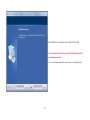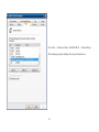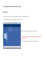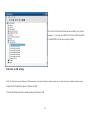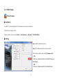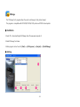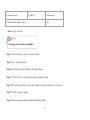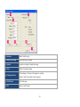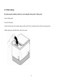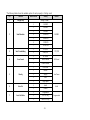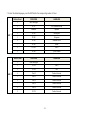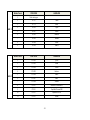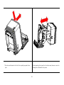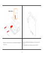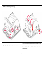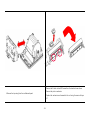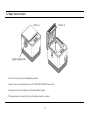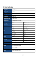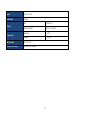
1
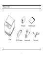
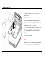
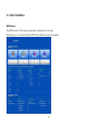
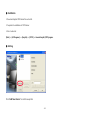
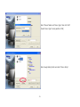
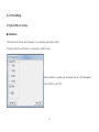
CONTENTS
Chapter 1. Introduction
Chapter 3. Product Settings
1-1 Warranty
3
3-1. Specifications
22
1-2. Copyright
4
3-2. Printer Setup
23
1-3. Safety Information
4
[Printer Firmware]
23
1-4. Liability Limitation
5
[NV Image Tool]
24
1-5. Installation Recommendations
7
3-3. Printer Settings
Chapter 2. Product Overview
27
Chapter 4. Maintenance
2-1. Inside Your Package
8
Printer Cutter Replacement
34
2-2. Product Outline
10
Motherboard Replacement
35
[Control Panel]
10
Printer Mechanism Replacement
40
[Connecting Cables]
11
[Installing Paper Roll]
12
5-1. Printer Self-test
42
2-3. Basic Installation
13
5-2. Paper Jam Correction
43
2-4. USB Settings
17
5-3. A7 Printer Specifications
44
[Physical USB port settings]
17
[Virtual COM port settings]
20
[Ethernet to USB settings]
21
Chapter 5. Printer Operation
-2-
Thermal Receipt Printer
Chapter 1. Introduction
1-1. Warranty
We guarantee our POS terminal product and its parts against defects in materials and workmanship, under proper use, for a standard period of
2 years from the original date of purchase.
During this period, we will repair or replace defective and/or faulty products or parts without charge to the customer for parts and labor.
The 1st year includes servicing and new or refurbished replacement parts free of charge, with one-way shipping costs borne by the seller. The
customer shall, however, be responsible for the return delivery costs.
The 2nd year also includes free of charge servicing and parts, but a limited warranty requires the entire shipping cost to be borne by the
customer.
Products out of the warranty period or scope shall be diagnosed at the customer's expense.
In the case of product damage due to error on part of the consumer, incorrect usage, carelessness or natural phenomenon, the customer shall
bear the full cost for both repair and delivery.
-3-
1-2. Copyright
This publication, including all photographs, illustrations and software, is protected under international copyright law with all rights reserved to the
manufacturer. Neither this manual, nor any of the material contained herein, may be reproduced without express written consent of the author.
1-3. Safety Information
1. Always ensure that the correct power voltage is used as a precaution against fire and electrical shock.
2. Avoid exposing product to direct sunlight. Do not use product in areas of high humidity.
Doing so may cause low reliability and/or operational malfunction.
3. Be careful of static electricity on PCB of system with anti-static appliances. Doing so may cause inferior reliability and shorted product life.
4. Keep product away from highly static areas. This may lead to inferior performance and reduced life cycle.
5. Do not interfere with, or obstruct metal components inside product. Doing so may cause the risk of fire or electric shock.
6. Do not pull on power cable or peripheral devices‟ connector cable. Doing so may cause fire, electric shock or electronic system malfunction.
7. Use caution when around other electronic devices with possible high frequency or electro-magnetic effects e.g. Audio, Electronic-range etc.
Doing so will lead to the serious risk of product malfunctioning or a system error occurring.
8. Ensure that batteries are replaced correctly. Failure to do this may result in sudden explosions.
9. Dispose of used batteries properly according to the instructions.
-4-
1-4. Liability Limitation
● Installation and maintenance
We recommend that you inquire about product installation, maintenance and repair service from the official service center and agent office.
AXON
takes no responsibility for malfunctions or system errors occurring after service and/or system check carried out by unofficial service providers.
● High frequency appliances
This product is qualified by FCC, CE, EMI and MIC compliances, and is thus governed by these qualifications‟ safety regulations.
However, the product can affect and be affected by other high frequencies generated around it. As such,
AXON
does not considerliability for any system
error or disorder due to this issue.
● Electronic noise emitting equipment
We recommend using the product away from electronic noise emitting equipment such as heaters, motors, fluorescent lights, TVs etc. as it may cause
interruption or interference with normal operation.
● Installation location
For optimal performance, the product should be kept in an environment of lower than 65% humidity and in a temperature of 10 ~ 30℃. Please also keep
away from direct sun-light.
-5-
● Cleaning procedure
Cleaning with chemical based products (in particular those containing benzyl or chemical thinning agents) can damage the exterior surfaces of the product.
We recommend using a soft damp cloth and wiping gently, taking particular care when dealing with the LCD display screen.
● Product limitations
1. The use of this product for anything other than POS tasks is strictly prohibited.
The product is not supported for regular PC and interface operation.
2. This product is for business use only, and not for usage in the home.
3. Both hardware and software are both fully configured.
4. Normal operating is guaranteed on a steady power connection.
-6-
1-5. Installation Recommendations
1. Avoid installing during thunderstorms. (Possibility of dangerous exposure to electricity.)
2. Install away from damp spaces or water-leaks.
3. Beware of static occurrence during installation.
4. Use only ground connected and quality certified power cords and cables.
5. Keep out of direct sun-light, extremely high or low temperatures, or high humidity areas.
6. Install product away from areas prone to shocks or vibration.
7. Install product away from sewing machines, welding equipment, electric stoves, audio equipment and other high frequency generating
equipment.
8. Installation and use in close proximity to an air-conditioning unit is not recommended.
9. Do not connect cables underneath carpets or floorboards.
10. Only use power cables supplied by pre-approved and certified venders.
11. Never use power cords from high power source appliances.
e.g. Electronic heaters, Electric stoves, Audio equipment, Air-conditioners, Refrigerators etc.
12. The use of multiple connections in a shared power outlet/socket is not recommended.
-7-
Thermal Receipt Printer
Chapter 2. Product Overview
2-1. Inside Your Package
Included in the package: Printer, power cable, interface cable, adapter, cable cover, roll paper, user manual and driver CD.
Please check that all items shown are included in your package. If anything is missing or damaged, please contact your dealer for
assistance.
-8-
[Package Contents]
-9-
2-2. Product Outline
(Note: Labels may differ according to model/region)
[Control Panel]
ERROR (LED)
: Blinks red when cover is open, no paper is installed or
Printer cannot function correctly.
POWER (LED)
: Steady green light is lit when power is on.
FEED (Button)
: Pressing the FEED button will eject paper. Continuously
holding down the button ejects paper until the button is
released.
-10-
[Connecting Cables]
1. Ensure that both the printer and host terminal are switched off.
2. Connect the power cable by first pulling back on the locking mechanism and
inserting into the printer‟s interface.
3. Connect to the power outlet using the adapter provided.
4. Connect the printer to the main terminal using the interface cable provided.
Ensure that all connections are correct and firmly secured.
5. If using a cash drawer, connect to the printer‟s interface using a drawer kick-out
cable.
Drawer kick-out cable
Interface connector
(Serial, USB)
Adapter
Power cord
-11-
[Installing Paper Roll]
1. Push down on the level to the left side of printer to
open the cover.
2. Switch off the power.
3. Remove any paper remaining inside the printer and
insert a new paper roll, ensuring that the end of the roll
is underneath. (as shown in the diagram)
4. Pull the end of the paper outside the machine and close
the cover, ensuring that the cover is locked properly
into place.
5. Switch the power back on.
[Note]
When closing the cover, press down on the center of the
cover to ensure the paper is in contact with the roller.
-12-
2-3. Basic Installation
OPOS Driver
The UNIPOS driver for OPOS driver system (based on Windows XP) is provided.
Alternatively, you can download the latest OPOS driver software at: www.axoncomputer.it
-13-
● Installation
1. Download EasySet OPOS driver file and install.
2. Complete the installation of OPOS driver.
3. File is located at:
[Start] –> [All Programs] –> [EasySet] –> [OPOS] –> Execute EasySet_OPOS prgram.
● Setting
Click “Add New Device” to install new printer.
-14-
Select „Device Name‟ and „Device Type‟, then click “Add”.
[„Select Device Type‟: Serial, parallel or USB]
Select newly added printer and enter “Device Setup”..
-15-
Enter port details in the Printer Settings page and press [OK] to
complete the setup.
※ When setting up the ‘Cash Drawer’, please use the same procedure as above.
-16-
2-4. Port settings
1. Physical USB port settings
● Installation
1. Download the A70 printer driver file relevant to your operating system (32bit or 64bit).
2. Double click the file and follow the on-screen steps to install the driver.
When installation is complete, open the program and go to: Port Management.
Under „USB Port‟, select „USB‟.
-17-
After installation is complete, connect the A70 USB cable
.
※ When connecting the A7O printer via USB, Physical/Actual USB
must always be selected.
※ For more detailed explanations, please refer to the Setting Mode.
-18-
Go to: Start -> Printers and faxes ->EASYSET PBP_A7 -> Printer settings
After checking the printer settings, the test print should be run.
-19-
2. Virtual COM (RS232 Serial Emulation) port settings
● Installation
1. Visit www.axoncomputer.it and download the file from „Others‟ -> „Virtual Serial Driver for A70‟.
2. Double click the file and proceed Install the A70 Virtual Serial Driver.
After installation is complete, connect the A70 USB cable
.
※ When connecting the A7O printer using this mode, Serial Emulation must
always be selected.
※ For more detailed explanations, please refer to the Setting Mode.
-20-
Once the A70 Virtual Serial Driver has been installed, go to: Device
manager -> Ports, and check that the A70 Printer Virtual Serial Port
For USB(COM2) Port has been correctly installed.
3. Ethernet to USB settings
※ NB: The A70printer supports Ethernet to USB connections via an external Ethernet module, however do not select this option unlessthe module is present.
1. Adjust the „A70 USB Mode ‟ option to „Ethernet to USB‟.
2. Connect the Ethernet module to enable printing via Ethernet to USB.
-21-
Thermal Receipt Printer
Chapter 3. Product Settings
3-1. Specifications
· Versatile & adaptable applications
· Robust and cost effective
· Paper Jam-free type printing
· Easy paper loading
· Auto-cutter
· RS232/USB interfaces
· Internal buzzer
· High performance CPU
· High resolution printing (up to 203dpi)
· Melody box extension compatibility
· ESC command plus Windows / OPOS driver support
· Epson /Star cash drawer emulation via DIP Switch
-22-
3-2. Printer Setup
Printer Firmware
● Installation
1. Insert CD or download EasySet Print Firmware driver www.axoncomputer.it
2. Install Printer Firmware driver
3. Main program can be found at: [Start] –> [All Programs] –> [EasySet] –> [PrintFirmWare]
● Setting
Step 1. Select [Interface] and [Port].
Step 2. Click [Download Start] and choose route.
After checking printer model, select [Firmware route].
- A7O
[C:\Program Files\EasySet\PrintFirmWare\A7\Firmware]
[Font route]
- A7O
[C:\Program Files\EasySet\PrintFirmWare\A7\Font]
-23-
NVImage
The „NV Image Tool‟ program allows the user to add images to the printed receipt.
The program is compatible with ECP-500/ECP-500A, F100 printer and P5000 internal printer.
● Installation
1. Insert CD or download EasySet NVImage driver file www.axoncomputer.it
2. Install NV Image Tool driver
3. Main program can be found at: [Start] –> [All Programs] –> [EasySet] –> [PrintNVImage]
● Setting
-24-
① Preview of image
② Open file
④ Uploads selected image to printer
③ Delete image
⑤ Exit
Step 1. Click ② [File Open]
.
Notice
Only single color .bmp files are compatible.
Step 2. Confirm the image is correct in ① preview window
Step 3. Click ④ [NVImage Upload]
Step 4. Select [Interface], [Serial Port Setting], [NV Image Printout]
Step 5. Click [Test Printout] to check that your image has uploaded correctly.
Step 6. After confirming the image is correct, click [Upload] to transmit the information to the printer.
Step 7. Click [OK] to save the changes.
Step 8. After the changes have been, the applied image will be printed.
-25-
① Interface
Selects interface type
② Serial Port Setting
Choose serial port settings
③ Upload
Uploads and applies the selected image
④ Clear
Deletes the selected image
⑤ NVImage Printout
Printing Range : Chooses which pages are required
Quality : Selects the quality of print required
⑥ Test Printout
Prints test page
⑦ OK
Save and exit settings
-26-
3-3. Printer settings
The printer properties (baudrate, density etc.) can be changed from the printer’s ‘Setting mode’.
To enter „Setting mode‟:
1. Switch off the printer.
2. Ensure that the paper roll is inserted properly and the end of the roll is outside the printer with the cover securely fixed.
3. While holding down the FEED button, switch on the power.
-27-
4. The printer‟s „Self-test‟ will begin.
5. Information about the printer‟s current state will be printed.
6. After 5 seconds without releasing the FEED button, the printer will enter „Setting mode‟.
7. The following properties available to be set will be printed:
*** Setting Mode ***
Interface : Serial
1. Step by Step
2. Serial Baudrate
3. Serial Handshaking
4. Error Sound
5. Density
6. Auto Cut
7. Auto Cut Mode
8. Code Page
9. USB Mode
-28-
* The following table shows the available options for each property in „Setting mode‟.
No
Function
1
Step by Step
2
3
4
5
6
7
Serial Baudrate
Serial Handshaking
Error Sound
Density
Auto Cut
Auto Cut Mode
Button Count
Setting
Default
Setting in order
1
2400 BPS
2
4800 BPS
3
9600 BPS
4
19200 BPS
5
38400 BPS
6
57600 BPS
7
115200 BPS
1
DTR/DSR
2
XON/XOFF
1
No Sound
2
Internal Buzzer
3
External Buzzer
1
Low Power
2
Normal
3
Slightly
4
Dark
5
High Speed
1
Install
2
Disable
1
Programable
2
Full Cut Only
3
Partial Cut Only
-29-
9600BPS
DTR/DSR
NO Sound
Low Power
Install
Programable
8
Code Page
9
※ Please refer to the table on the right.
USB Mode
1
Serial Emulation
2
Actual USB
3
Ethernet to USB
Actual USB
For example,
To set the „Serial baudrate‟ to 38,400bps:
- When in „Setting mode‟, press the FEED button twice(2), as displayed on the print out, to enter the „Serial baudrate‟ submenu.
- After 2 seconds, the following options will be printed:
Serial Baudrate:
1. 2400bps
2. 4800bps
3. 9600bps
4. 19200bps
5. 38400bps
6. 57600bps
7. 115200bps
- Find the option that you wish to change the property to, in this instance „5-38400bps‟, and press the FEED button the corresponding
number of times (i.e. five times)
- After 2 seconds, the new settings will be printed. In this instance:
Baudrate : 38400bps*
[
*
The current settings are displayed. ]
※ To make any other changes to the printer‟s properties, please follow the method above.
-30-
* To select the desired language, press the FEED button the corresponding number of times.
PAGE 1
PAGE 2
Button Count
CODE PAGE
LANGUAGE
1
Next code page
2
CP-437
USA, Standard Europe
3
Katakana
Japanese
4
CP-850
Multilingual
5
CP-860
Portuguese
6
CP-863
Canadian-French
7
CP-865
Nordic
8
CP-1252
Latin l
9
CP-866
Cyrillic Russian
Button Count
CODE PAGE
LANGUAGE
1
Next code page
2
CP-852
Latin ll
3
CP-858
Euro
4
Thai-42
Thailand character
5
Thai-11
Thailand character
6
Thai-14
Thailand character
7
Thai-16
Thailand character
8
Thai-18
Thailand character
9
CP-874
Thailand character
-31-
PAGE 3
PAGE 4
Button Count
CODE PAGE
LANGUAGE
1
Next code page
2
CP-737
Greek
3
CP-775
Baltic
4
CP-855
Cyrillic
5
CP-857
Turkish
6
CP-861
Icelandic
7
CP-862
Hebrew
8
CP-864
Arabic
9
CP-869
Greek ll
Button Count
CODE PAGE
LANGUAGE
1
CP-1251
Cyrillic
2
CP-1253
Greek
3
CP-1254
Turkish
4
CP-1255
Hebrew
5
CP-1256
Arabic
6
CP-1257
Baltic
7
CP-1258
Vietnam
8
CP-950
Traditional Chinese BIG 5
9
CP-936
Simplified Chinese GBK
10
CP-932
Japanese Shift-JIS
11
CP-949
Korean
-32-
Thermal Receipt Printer
Chapter 4. Maintenance
This section shows the user the correct way to remove and replace the printer cutter, motherboard and printer mechanism for the
AXON POS A70 printer.
-33-
[Printer cutter replacement]
1. Open the printer cover and remove the 2 screws from the cutter (as shown above).
2. Remove the cutter.
3. Replace the cutter using the reverse procedure of steps 1-2 above.
-34-
[Motherboard replacement]
1. Remove the power cable from the unit and open the cover by pressing
2. Remove the screw attached to the center of the lever and detach as
down on the level to the left of the printer.
shown above.
-35-
FISCAL Option
3. Remove the 2 flat-headed screws from the locations shown above.
4. Remove the 2 screws from the underside of the printer (as shown above).
-36-
5. Ensuring that the cover is open, pull vertically upwards to separate the top
6. The side of the printer should look at above. (At this point, switch the
casing from the bottom casing.
power to ON to avoid any damage when removing.)
-37-
7. Push down and forward on the front lid to completely separate the two
8. When separating the top case from the bottom case, take care so as not to
parts.
damage the motherboard in the process.
-38-
FISCAL Option
9. Remove the 3 screws from the face of the motherboard and separate from
10. Replace the motherboard and reassemble the unit using the reverse of
steps 1-9.
the main unit.
(During reassemble, ensure that the power switch is set to OFF.)
-39-
[Printer mechanism replacement]
2. Remove the 2 screws from the location behind the motherboard (as shown
1. Remove the motherboard as shown in the previous section.
above).
3. Remove the final screw from the side of the mechanism and remove the
cover opening lever.
-40-
5. Remove the 6 black circular M2.0 screws from the location shown above.
4. Remove the top casing from the motherboard panel.
6. Remove the printer mechanism.
7. Replace the mechanism and reassemble the unit using the reverse of steps
1-7.
-41-
Thermal Receipt Printer
Chapter 5. Printer Operation
5-1. Printer Self-test
1. Make sure the paper roll is installed correctly.
2. While holding down the FEED button, turn on the printer to begin self-test.
3. The self-test will print out the current ROM version and DIP switch settings.
4. When self-test is complete, release the FEED button.
5. Press the FEED button one more time to print the current font setup.
6. The printer is now ready to receive data.
-42-
5-2 Paper Jam Correction
1. In the event of a paper-jam, immediately stop printing.
2. Open the top cover by pressing down on the „COVER OPEN BUTTON‟ shown above.
3. By opening the cover, the paper-jam will be automatically resolved.
4. If the paper-jam is not correctly by this method, please contact your dealer.
-43-
5.3 Printer Specifications
Printing Method
Direct thermal
Printing Speed
170mm/sec
Dot Density (DPI)
203.2
Dot Pitch (mm)
0.125*0.125
Effective Printing Width
72mm, 576dots
Printing Direction
Unidirectional with friction feed
Character/Line
Paper
Reliability
Character/Set
Font A
(12*24) 42 columns
Font B
(10*20) 56 columns
Type
Thermal paper
Width
79.5mm (±0.5mm)
Thickness
0.07mm
Roll diameter
83 Ømm
TPH Life
100km
MCBF
60,000,000 lines
Alphanumeric character
95
Extended graphic
128 x 35 page
Barcode
EAN-8, EAN-13, CODE39, CODE93, CODE128, ITF, UPC-A, UPC-E, CODABAR
Emulation
ESC/POS command compatible
Driver
Windows / OPOS
Interface
Serial / USB / Ethernet / Wi-fi
-44-
Power
24 VDC / 2.5A
Data Buffer
4 Kbyte
Cutting
Temperature
Life
700,000 cuts
Cutting method
Partial Cut / Full Cut
Operation
0 ~ 40℃
Storage
-20 ~ 60℃
EMI Standard
CE, FCC, KCC
Dimension (WxHxD)
136 x 162.5 x 122(mm)
-45-