1
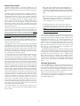
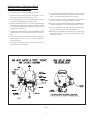
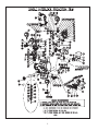
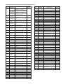
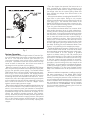
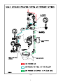
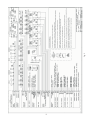
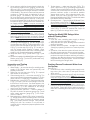
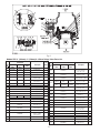
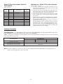
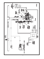
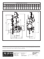
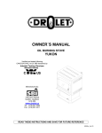
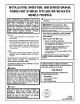
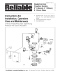
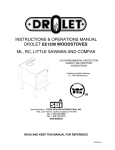
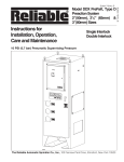
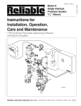
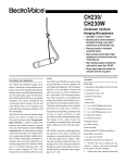
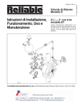
Bulletin 739
Instructions for
Installation, Operation
Care and Maintenance
For Single Interlock Preaction Systems
With Dual Solenoid Actuation
Of Pneumatic Pilot Release
4"(100mm),
6"(150mm) & 165mm
Sizes with Trim
• LPCB Approved
• Redundant Solenoid Valve
Release
• Rated to 175 psi (12.1 bar)
• Externally Resetable
Clapper
• One Main Drain
The Reliable Automatic Sprinkler Co., Inc., 103 Fairview Park Drive, Elmsford, New York 10523
Bulletin 739
Single Interlock
Preaction System
General Description
A. A fire alarm sounds prior to the operation of a
sprinkler head, which may enable extinguishing
the fire by handheld means before the actual operation of any sprinklers and subsequent water damage.
Reliable Single Interlock Preaction Systems are designed for water-sensitive areas that require protection
from inadvertent water flow into the sprinkler system piping.
Sprinkler piping in single interlock systems can effectively be supervised by means of a Reliable Model A-2
Pressure Maintenance Device and a tank-mounted air
compressor. Loss of supervising pneumatic pressure,
due to a damaged sprinkler or sprinkler pipe will not
cause water to flow through the Model DDX Deluge
Valve and into the system piping. A significant loss of
pneumatic pressure will activate a trouble-annunciating
device when the system pressure falls below a predetermined pressure level.
When one electrical detector senses the presence of
fire, the electrical releasing control panel activates fire
alarm devices and energizes the two redundant, normally-closed solenoid valves in the open position (Note:
Arranging detectors in a cross-zoned pattern will require
operation of two detectors before the solenoid valves
can open). These solenoid valves, when closed, retain
sufficient AIR pressure in the Model LP Pilot Line Actuator, which in turn preserves sufficient WATER pressure in
the push rod chamber of the Model DDX Deluge Valve in
order to maintain it closed.
Energizing the solenoid valves relieves the air pressure
in the Model LP Dry Valve Actuator (see Fig. 8), thereby
releasing the water pressure that it was retaining. This is
turn relieves the pressure in the push rod chamber of the
Model DDX Deluge Valve. Venting this push rod chamber will open the Model DDX Deluge Valve and allow water to flow into the sprinkler system.
To fully operate a cross-zoned single interlock system,
two electrical detectors must activate and a sprinkler
head must open. During the early stages of a fire, smoke
or heat activates the first detector, which causes the control panel to produce a local alarm and an alarm at the
main fire alarm panel. Electrical relays inside the releasing control panel can be used to shut down airmoving
equipment or activate security doors and other electrical
devices. Subsequent activation of a second, nearby or
adjacent detector will cause the panel to energize the
solenoid valves open and release water into the sprinkler
system piping. Water flowing into the sprinkler system
piping will simultaneously produce water pressure that
causes the transfer of contacts in the pressure switch
mounted in the trim. This pressure switch can electrically
initiate the shutdown or startup of equipment, such as
computers or other second alarm devices. This flow of
water into the sprinkler system piping effectively converts the dry system into a wet pipe system. In the event
that the fire subsequently produces sufficient heat to operate a sprinkler head, water will flow from that sprinkler,
controlling or suppressing the fire.
The major benefits of a single interlock preaction system, when compared with a wet pipe (deluge) system
are as follows:
B. A trouble annunciator signals whenever the integrity of the piping or sprinklers is accidentally or
intentionally disturbed; however, no water flow or
water damage will occur at that time.
C. Speedy detection and an early fire alarm are
provided by fire detectors, without the delay associated with water delivery time in the event of a fire.
Note: with a wet pipe system, the fire alarm is delayed until after water has begun flowing from an
operated sprinkler head.
At the heart of Reliable’s Single Interlock Preaction System is the Model DDX Deluge Valve. This Deluge Valve is
a hydraulically operated, straight-through-design, differential-type valve (see Fig. 1). System maintenance is
simplified since priming water is not required and the
deluge valve can be reset externally without cover removal. This is accomplished by pushing in and turning
the external reset knob at the rear of the deluge valve
(see Fig. 1). This feature provides a significant system-restoration time advantage.
The Reliable Single Interlock Preaction System trim set
(see Fig. 2) provides all of the necessary equipment for
connections to the Model DDX Deluge Valve’s pushrod
chamber inlet and outlet ports, the 2” (50mm) main
drain, alarm devices, air supply, water supply, and required pressure gauges. This trim set is available in individual parts, in time-saving, segmentally assembled kit
forms, or fully assembled to the Model DDX Deluge
Valve.
Listing & Approvals
The 4” (100mm), 6’ (150mm) and 165mm Single Interlock Preaction Systems shown in this bulletin must only
be used in the combination described herein to be Loss
Prevention Certification Board (LPCB) approved. Installation of these systems must be according the requirements of Technical Bulletin TB21:1994:1.
The majority of the system’s components are individually Listed by Underwriters Laboratories Inc. and Factory Mutual Approved.
2.
Loss Prevention Certification Board
(LPCB) Installation Requirements of
Preaction systems Include:
1. Solenoid valves shall be installed in parallel.
2. Solenoid valves shall function in pneumatic conditions only, and be protected by a strainer.
8. Pre-action system equipment shall be installed, operated and maintained as prescribed in the firm’s installation , operating and maintenance manual.
3. LPCB Certified detectors compatible with the control
and indicating equipment shall be used.
9. Pre-action systems shall be configured in accordance
with the manufacturer’s defined specifications.
4. Suitable electrical detection, control and indicating
equipment and pneumatic systems shall be used.
The control and indicating equipment shall be LPCB
approved / certificated.
10.Pre-action systems shall comply with the details specified in the related LPC Technical Bulletin (Ref. TB21).
5. Connecting cables shall comply with BS 6387:1983,
classification C, W, Z evidenced by LPCB certification.
12.Normally un-energized solenoids may be used, provided that they are continuously monitored for ‘open’
and ‘short circuit.’
11.The firm responsible for the complete pre-action station, including electrics, shall be identified.
6. Pre-action systems shall be electrically monitored to
demonstrate that they are in a ‘ready to operate’
state at all times.
7. Clear dry air shall be used. Compressor tank must
have provision for draining.
Fig. 1
3.
Fig. 2
3.
SINGLE INTERLOCK PREACTION SYSTEM PARTS LIST (REFER TO FIG. 2)
ITEM
NO.
PART
NUMBER
6103040026
1
6103060024
6103060028
2
78653004
3
98048000
4
98048015
5
98048022
6
98048025
7
92056809
8
92056810
9
92056811
10
92056702
11
92056704
12
13
14
15
16
17
18
19
20
98085666
98050004
98174400
98174403
98174401
98174404
98174405
98174402
96920912
21
98240006
22
98240101
23
6304000100
24
78653000
25
71030010
26
94616917
27
28
29
30
31
32
33
34
35
36
98543222
98543266
98543213
98543223
98543210
98543216
98543209
98543230
98543237
98543226
DESCRIPTION
MODEL DDX VALVE,
ASSEMBLY, 4" (100MM)
MODEL DDX VALVE,
ASSEMBLY, 6" (150MM)
MODEL DDX VALVE,
ASSEMBLY, 165 MM
ASSEMBLY, VALVE CAUTION
STATION, 1/2"
BUSHING, REDUCER,
1/2" x 1/4", GALV.
BUSHING, REDUCER,
2" SPIGOT x 1" NPTF, PVC
BUSHING, REDUCER,
3/4" X 1/2", GALV.
BUSHING, REDUCER,
3/4" X 1/4", GALV.
CONNECTOR ASSEMBLY,
NO-LOSS, 3/8 x 1/2 NPT
CONNECTOR,
3/8" ID TUBE x 1/2" NPT
CONNECTOR,
3/8" ID TUBE x 1/4" NPT
CONNECTOR,
3/8" TUBING x 1/4" NPT
CONNECTOR, ELBOW,
3/8" ID TUBE x 1/2" NPT
REDUCER, 1/2" x 1/4"
DRAIN CUP, PVC
ELBOW, STREET, 1/2"
ELL, 1"
ELL, 1/2"
ELL, 1/4"
ELL, 2"
ELL, 3/4"
FLEX LINE, 12"
GAUGE, WATER PRESSURE
(16 BAR) W/ CONNECTOR
GAUGE, WATER PRESSURE
(6 BAR) W/ CONNECTOR
MOD. A-2 AUTO AIR
MAINTENANCE DEVICE, 10PSI
MODEL B MANUAL
EMERGENCY STATION
MODEL LP
DRY VALVE ACTUATOR
NAMEPLATE,
SINGLE INTERLOCK
NIPPLE, STEEL, 1" X 3-1/2"
NIPPLE, STEEL, 1" X 6"
NIPPLE, STEEL, 1" X CLOSE
NIPPLE, STEEL, 1/2" X 1-1/2"
NIPPLE, STEEL, 1/2" X 2-1/2"
NIPPLE, STEEL, 1/2" X 3-1/2"
NIPPLE, STEEL, 1/2" X 2"
NIPPLE, STEEL, 1/2" X 3"
NIPPLE, STEEL, 1/2" X 8"
NIPPLE, STEEL, 1/4" X 1-1/2"
NO
REQ'D
1
1
4
1
1
2
1
1
1
1
1
4
1
1
1
1
1
1
2
1
2
2
1
1
1
1
1
1
1
17
1
1
2
1
1
21
3.
ITEM
NO.
PART
NUMBER
DESCRIPTION
NO
REQ'D
37
38
39
40
41
42
43
44
45
46
47
48
49
50
51
52
53
54
55
98543225
98543244
98543220
98543243
98543227
98543208
98543238
98543215
98543233
98543232
98543279
99080002
98750003
98604406
98614403
98614401
98681630
78650201
98727607
1
1
2
1
1
2
1
1
1
1
3
1
2
1
5
3
1
1
1
56
96556922
57
58
59
60
61
62
63
64
65
66
67
68
69
70
71
72
73
74
75
76
77
78
79
80
96606627
96606607
98761649
98761651
96606608
96606612
96606601
89141112
98815204
98815200
98815201
98815202
98840160
98840101
98840100
78653100
98840110
98840144
98840145
98840181
98840171
6871020010
6871020000
98840193
81
96686722
82
96686756
NIPPLE, STEEL, 1/4" X 2-1/2"
NIPPLE, STEEL, 1/4" X 2"
NIPPLE, STEEL, 1/4" X 3"
NIPPLE, STEEL, 1/4" X 4"
NIPPLE, STEEL, 1/4" X CLOSE
NIPPLE, STEEL, 2" X 3"
NIPPLE, STEEL, 2" X CLOSE
NIPPLE, STEEL, 3/4" X 1-1/2"
NIPPLE, STEEL, 3/4" X 2-1/2"
NIPPLE, STEEL, 3/4" X 2"
NIPPLE, STEEL, 3/4" X CLOSE
PAD-ADHESIVE
PIPE CROSS, 1/2"
PLUG, SQ. HD., 1/2"
PLUG, SQ. HD., 1/4"
PLUG, SQ. HD., 3/4"
REGULATOR, AIR LINE
STRAINER, 1/2" NPT
STRAINER, 1/4"
SWITCH, PRESSURE,
BAILEY & MACKEY
TEE, GLVN, 2 X 2 X 1
TEE, GLVN., 1/2 X 1/2 X 1/4
TEE, GLVN., 1/2 X 1/4 X 1/2
TEE, GLVN., 1/2"
TEE, GLVN., 1/4 X 1/4 X 1/4
TEE, GLVN., 3/4 X 1/2 X 1/2
TEE, GLVN., 3/4"
TIE, RETAINING
UNION, "O" RING SEAL, 1/2"
UNION, 1/2", IRON, G.J., GALV.
UNION, 1/4", IRON, G.J., GALV.
UNION, 3/4", IRON, G.J., GALV.
VALVE, 3-WAY, 1/4"
VALVE, ANGLE, 1/4"
VALVE, ANGLE, 2"
VALVE, BALL DRIP, 1/2"
VALVE, BALL, 1/4"
VALVE, CHECK GAUGE
VALVE, CHECK, 1"
VALVE, CHECK, 1/2"
VALVE, GLOBE, 1/2"
VALVE, SOLENOID ASCO
VALVE, SOLENOID SKINNER
VALVE, SPRING CHECK, 1/4"
TUBING, COPPER,
3/8" O.D. X 2 FT
TUBING, PVC, 3/8" I.D. x 6 FT
1
1
1
2
2
3
1
2
3
1
2
3
1
4
1
1
1
1
2
1
1
1
1
1
2
1
1
Fig. 3
System Operation
To fully operate a Reliable Single Interlock Preaction System, two independent events must coexist before water flow
will occur. One electrical detector (two detectors in a
cross-zoned system) must activate and a sprinkler head
must open. Operation of either one of these items will only
cause an alarm to annunciate, but will not cause water to
discharge from the sprinkler system piping.
When set correctly for service, the Model DDX Deluge
Valve is hydraulically established to withhold the supply water from the sprinkler system piping. The Reliable Model
DDX Deluge Valve is shown in both closed and open positions in Fig.1. In the closed position, the supply pressure
acts on the underside of the clapper and also on the push
rod through the push rod chamber’s inlet restriction. The resultant force due to the supply pressure acting on the push
rod is multiplied by the mechanical advantage of the lever
and is more than sufficient to hold the clapper closed
against normal supply pressure surges.
When a fire is detected, the energized solenoid valves vent
the air from the Model LP Dry Valve Actuator (see Fig. 8),
which in turn vents the push rod chamber to atmosphere
through the chamber’s outlet. Since the pressure cannot be
replenished through the inlet restriction as rapidly as it is
vented, the pushrod chamber pressure falls instantaneously. When the pushrod chamber pressure approaches
approximately one-third of the supply pressure, the upward
force of the supply pressure acting beneath the clapper
overcomes the lever-applied force thereby opening the
clapper.
6.
Once the clapper has opened, the lever acts as a
latch, preventing the clapper from returning to the
closed position. Water from the supply flows through
the deluge valve into the system piping. Water also
flows through the deluge valve alarm outlet to the
alarm devices.
After system shutdown, resetting the Model DDX Deluge Valve is quite simple. Doing so only requires
pushing in and turning the reset knob at the rear of the
valve (see Fig.1). The external reset feature of the
Model DDX Deluge Valve provides a means for simple, economical system testing, which is one essential
facet of a good maintenance program.
The external reset feature does not, however, eliminate another important facet of good maintenance,
namely, periodic cleaning and inspection of the internal valve parts. In the event that water builds up inside
the valve due to condensate from the air supply system or water left inside from valve system testing, a
drain is available for venting. After closing the main
supply valve, a small valve over the drain cup can be
opened slightly until the water inside the valve body
and the main pipe column has drained. See the section titled “Draining Excess/Condensate Water From
System” in this bulletin for the detailed procedure.
The Model B Manual Emergency Station (see Fig. 3)
is also included in the trim set. It consists of an aluminum nameplate mechanically attached to a ball valve.
The valve handle in its OFF position is guarded
against accidental turning to the ON position (and
system discharge) by a nylon cable tie provided with
each trim kit. The cable tie is inserted, as shown in Fig.
3, after the system has been restored for operation.
The nylon cable tie is designed to allow, in case of an
emergency, forceful turning of the valve handle to the
ON position. As an alternative to the Model B Hydraulic Manual Emergency Station, the Model A Hydraulic
Manual Emergency Pull Box (see Reliable Bulletin
506) is also available and can be provided as an option.
Whenever ambient temperature conditions are high,
the water temperature in the Model DDX Deluge
Valve’s pushrod chamber could possibly increase,
thereby increasing the pressure in the chamber to values exceeding the rated pressure of the system. In an
indoor installation where standard room temperatures
are exceeded, a pressure relief kit may be needed.
Pressure relief kit, P/N 6503050001, can be installed
into the pushrod chamber’s releasing line to limit the
pressure to 175 psi (12,1 bar).
Pressurizing Line Connection
The water supply for the push-rod chamber must be
provided by connection of its inlet pressurizing line to the
water supply piping. Pressurizing lines for multiple
Model DDX Deluge Valve push-rod chambers must
never be manifolded together, having only a single tap
on the water supply piping. Each Model DDX Deluge
Valve must have its own push-rod chamber pressurizing
line connection. This connection must be made on the
supply side of the main water supply control valve. This
can be accomplished by:
a. Using a tapped connection directly below or next to
the main water supply control valve using a welded
outlet or the appropriate mechanical fittings. A
grooved-end outlet coupling is one way to achieve
this.
b. Using a water supply control valve that has an available threaded (NPT) supply-side tap design to allow
for a direct water supply connection to the Model DDX
Deluge Valve’s push-rod chamber.
The sections of the preaction trim that contains the two
redundant normally-closed solenoid valves, and the upper portion of the Model LP Dry Valve Actuator, require
pneumatic pressure settings per Table A. When establishing the preaction system for service, refer to Table A of
this bulletin for the correct pneumatic pressure settings for
a corresponding water supply pressure. Note: During
the initial system set-up, a higher pneumatic pressure
may be required in order to properly seat the internal diaphragm of Model LP Dry Valve Actuator.
Refer to Reliable Bulletin 251 and/or Fig. 3 of this bulletin
for instructions on how to modify these pressure settings.
Table A
Water Pressure Pneumatic Pressure to be Pumped
psi (bar)
into Sprinkler System, psi (bar)
Maximum
Not Less Than
Not More Than
20
50
75
100
125
150
175
Caution: Reliable’s Model DDX Deluge Valve is designed with an inlet restriction built into the pushrod
chamber. It is important not to introduce additional restrictions into the direct water supply connection or the
discharge from the pushrod chamber by installing additional valves or improperly installing the copper lines
used in the trim of the valve.
(1,4)
(3,4)
(5,2)
(6,9)
(8,6)
(10,3)
(12,1)
10
12
13
15
16
17
18
(0,7)
(0,8)
(0,9)
(1,0)
(1,1)
(1,2)
(1,2)
14
16
17
19
20
21
22
(0,9)
(1,1)
(1,2)
(1,3)
(1,4)
(1,4)
(1,5)
System Design Considerations
The automatic sprinklers, air compressor, releasing devices, electric releasing control equipment, fire detection devices, manual pull stations, and signaling devices
which are utilized with this Reliable Single Interlock
Preaction System must be Loss Prevention Certification
Board (LPCB) approved, as applicable.
The deluge valve and all interconnecting piping must
be located in a readily visible and accessible location
and in an area that can be maintained at a minimum temperature of 40°F (4°C). Note: Heat tracing is not permitted.
The redundant solenoid valves are operated and supervised by an electrical releasing/control panel. Details
on the electrical connections and the Prescient Pre-Action Sprinkler Extinguishing Fire Alarm Panel can be
found on Figure 5 of this bulletin.
System Electrical Requirements
All releasing, alarm and detection devices in this Reliable
Single Interlock Preaction System are supervised by the
Prescient Pre-Action Sprinkler Extinguishing Fire Alarm
Panel. Connect these devices as shown in Fig. 5. The
power supply, the standby emergency power supply, battery charger, and the rectifier circuitry are all contained
within this panel. For additional and detailed wiring information, refer to the manufacturer’s literature included with
the Prescient Releasing Control Panel. Caution: Repairs
or disassembly of the solenoid valves should only be
done by a trained technician. An improperly repaired or
partially assembled solenoid valve could result in failure of
the valve to operate.
System Air Pressure Requirements
When a Reliable Single Interlock Preaction System is
utilized, the sprinkler system piping requires a minimum
of 7 psi (0,5 bar) supervisory pneumatic pressure. The
Model A-2 Pressure Maintenance Device, along with an
additional air pressure regulator, are used to maintain
the system’s pneumatic pressure between 7 and 10 psi
(0,5 and 0,7 bar) where a dry nitrogen gas supply or a
clean, dependable, and continuous (24 hours per day, 7
days per week) compressed air source is available.
7.
Fig. 4
8.
9.
Fig. 5
Technical Data
formula with C=120 and a flow velocity of 15ft/sec
(4.6 m/sec)):
7. Installation position: Vertical
Reliable Single Interlock Preaction Systems, with associated trim, sizes 4” (100mm), 6” (150mm) and 165mm
are rated for use at minimum water supply pressure of 20
psi (1,4 bar) and maximum supply pressure of 250 psi
(17,2 bar). Water supplied to the inlet of the valve and to
the pushrod chamber must be maintained between 40°F
(4°C) and 140°F (60°C).
The following list of technical bulletins pertains to valves
and devices that may be used in this preaction system:
Deluge Valve
Reliable 510/511
Hydraulic Emergency Station (Model A)
Reliable 506
Solenoid Valve
Reliable 707
Mechanical Sprinkler Alarm
Reliable 612/613
Pressure Maintenance Device
Reliable 252
Air Compressor
Reliable 707/708
Electric Emergency Station
Reliable 707
Thermal/Smoke Detectors
Reliable 707
Fire Alarm Devices
Reliable 707
Waterflow Pressure Alarm Switch
Bailey & Mackey Ltd.
Model 1381V
Valve Size
4" (100mm)
6" (150mm) & 165mm
Maintenance
Reliable Single Interlock Preaction Systems and associated equipment shall periodically be given a thorough
inspection and test. NFPA 25, Inspection, Testing and
Maintenance of Water Based Fire Protection Systems,
provides minimum maintenance requirements. System
components shall be tested, operated, cleaned, and inspected at least annually, and parts replaced as required.
Resetting the Single Interlock Preaction
System
Refer to Figs. 2, 6, and 7.
1. Close the main valve controlling water supply (Fig.
7) to the Deluge Valve and close off the air supply to
the sprinkler system at the air supply’s source.
2. Close the pushrod chamber supply valve, valve A
(Fig. 7).
3. Open the main drain valve, valve B (Fig. 7), and
drain system.
4. Open all drain valves and vents at low points
throughout the system, closing them when flow of
water has stopped. Open valve D (Fig. 7). Note:
The above steps accomplish the relieving of pressure in the pushrod chamber of the Deluge Valve.
5. With Valve F (Fig. 7) open, push in the plunger of ball
drip valve, valve G (Fig. 7), to force the ball from its
seat, and drain any water in the alarm line.
6. With the Model B Manual Emergency Station, valve
D (Fig. 7), open, push in and rotate the deluge
valve’s external reset knob (#38, Fig. 6) clockwise
until you hear a distinct clicking noise, indicating that
the clapper has closed. Note: The reset knob can
be rotated only after pressure in the pushrod chamber has been reduced to atmospheric conditions (0
psig).
7. Inspect and replace any portion of the sprinkler system subjected to fire conditions.
8. Close valve F (Fig. 7). Activate a solenoid-release
pull station (Or other means of electric detection.) to
energize the solenoid valve(s). Silence any alarms
or audible tones on the releasing/control panel.
Open valve A (Fig. 7) to begin pressurizing the
push-rod chamber and its associated piping, while
simultaneously venting any entrapped air. Note:
This venting of the air from the actuation piping is
very important to ensure proper system operation
and avoidance of falsely tripping the Deluge Valve.
Valve Description
1. Rated working pressure:
Valve & System - 175 psi (12,1 bar)
2. Factory tested to a hydrostatic pressure of 500 psi
(34,5 bar). (Valve only)
3. End and trim connections:
• ANSI/AWWA C606 grooved inlet and outlet
Valve
Size
4"
(100mm)
165mm
6"
(150mm)
Groove Dimensions
Outlet
Groove
Groove
Diameter
Diameter
Width
4.500"
4.334"
(114mm)
(110)
3 "
6.500"
6.330"
8
(165mm)
(161mm)
(10mm)
6.625
6.455"
(168mm)
(164mm)
Outlet Face
to Groove
5 "
8
(16mm)
• Threaded openings Per ANSI B 2.1
4. Face to face dimensions:
Valve Size
4" (100mm)
6" (150mm)
165mm
Color
Black
Red
• 4" (100 mm) — 14” (355 mm)
• 6" (150 mm) & 165 mm — 16” (406 mm)
5. Shipping weight:
6. Friction loss (Expressed in equivalent length of
Valve Size
Weight
4" (100 mm)
6" (150 mm) & 165mm
64 lb. (29 kg)
95 lb. (43 kg)
Equivalent Length
14' (4.27 m)
29.4' (9 m)
Schedule 40 pipe, based on Hazen & Williams
10.
9. Upon seeing a solid flow of water from the drain tubing, and the cessation of the “gurgling” sound at the
drip cup, H (Fig. 7), close valve D (Fig. 7) then rapidly
apply compressed air or nitrogen into the to chamber
of the Model LP Dry Valve Actuator until the pressure
conforms to Table A levels as indicated on the air
pressure gauge. The Model LP Dry Valve Actuator
will close during this pressurizing process and the
water will stop flowing into the drip cup. At this point,
the pressure gauge which indicates push-rod chamber pressure (Fig. 7) will equalize to the available water supply pressure. Note: It may be necessary to
isolate the various pressure gauges in the trim during
system set-up by closing the ¼” 3-way valves (#68
Fig. 2) that they are connected to. During set-up,
pressure fluctuations may occur that can be potentially damaging to the gauges.
10. De-energize the solenoid valve(s). This is accomplished by resetting the solenoid-release pull station
and/or the detectors that were activated in Step #8
above. Note: All detection devices must be reset before the releasing/control panel can be reset.
11. Open valve F (Fig. 7). Open slightly the main valve
controlling water supply (Fig. 7) to the deluge valve,
closing drain valve B (Fig. 7) when water flows. Observe if water leaks through the ball drip valve, valve
G (Fig. 7), into the drip cup, H (Fig. 7). If no leak occurs, the seluge valve’s clapper is sealed. Open
slowly, and verify that the main valve controlling water
supply is fully opened and properly monitored.
12. Verify that valve A (Fig. 7) and valve F (Fig. 7) are
open.
13. Secure the handle of the Model B Manual Emergency
Station, valve D (Fig. 7), in the OFF position with a nylon tie (#64, Fig. 2).
7. Testing alarms — make sure that valve F (Fig. 7) is
open. Open valve C (Fig. 7) permitting water from the
supply to flow to alarm portion of the trim. Typical devices that are connected to this section of the trim are
pressure switches and/or a mechanical sprinkler
alarms (water motor). After testing has been completed, close this valve securely. Push in on the
plunger of ball drip valve G (Fig. 7) until all of the water
has drained from the alarm line.
8. Operational test — Open the Model B Manual Emergency Station, valve D (Fig. 7). Note: An operational
test will cause the deluge valve to openand flow water
into the sprinkler system.
9. Secure the Model B Manual Emergency Station,
valve D (Fig. 7), in the OFF position with a nylon tie
(#64, Fig. 2) after the deluge valve is reset.
Inspection and Testing
Draining Excess/Condensate Water from
the System
Testing the Model DDX Deluge Valve
without Flowing Water
Refer to Fig. 7
1. Close the valve controlling water supply to deluge
valve and open the main drain valve B.
2. Verify that valve A is open, allowing water to enter the
push rod chamber.
3. Operate detection system – energize the solenoid
valve(s) by operating a detector or manual pull station.
4. Operation of the detection system will result in a sudden drop of water pressure in the push rod chamber.
5. Reset the detection system — reverse the operations
performed in step three above and then proceed according to the directions listed in the “Resetting the
Single Interlock Preaction System” section of this bulletin for resetting the Deluge Valve.
Refer to Figs. 2, 6, and 7.
1. Water supply — be sure the valve(s) controlling water
supply to the Deluge Valve are opened fully and
properly monitored.
2. Alarm line—be sure that valve F (Fig. 7) is opened
and remains in this position.
3. Other trimming valves — check that valve A (Fig. 7) is
open as well as all of the pressure gauge’s ¼” 3-way
valves. Valves C, D, and E (Fig. 7) should be closed.
4. Ball drip valve, valve G (Fig. 7)—make sure that valve
F (Fig. 7) is open. Push in on the plunger to be sure
the ball check is off its seat. If no water appears, the
deluge valve’s water seat is tight. Inspect the bleed
hole (see Fig. 7) on the underside of the deluge
valve’s push rod chamber for leakage.
5. System pneumatic pressure — check the Model LP
Dry Valve Actuator’s air pressure gauge (Fig. 7) and
water supply pressure gauge (Fig. 7) for conformance to Table A.
6. Releasing device - Model LP Dry Valve Actuator (Fig.
7). Verify that the outlet is not leaking water. Check the
Model LP Dry Valve Actuator’s air pressure gauge
(Fig. 7) for proper pressure settings. Verify that the
tubing line from the actuator is not pinched or
crushed, which could prevent proper operation of the
deluge valve.
Refer to Fig. 7
1. Close the main valve controlling water supply to deluge valve. Also, close valve A and open the main
drain valve B.
2. Open the condensate drain valve E until all of the water has drained. Close valve E. Note: Be sure not to
keep valve E open for an extended period of time because that will cause enough system air to bleed off,
thereby causing an undesirable activation of a trouble/alarm-annunciating device.
3. Close the main drain valve B. If system contains pressurized air, allow the air pressure to come back up to
specification. Open valve A first, and then open the
main valve controlling the water supply to the deluge
valve.
11.
Fig. 6
Models DDX 4" (100mm), 6" (150mm) & 165mm Deluge Valve Parts List
Part Number
Item
No
165mm
Valve
1
2
3
4
4"(100mm)
Valve
91006005
96016004
91916004
92116064
6"(150mm)
Valve
91006007
96016006
91916006
92116066
91006027
96016006
91916006
92116065
5
93416004
93416006
93416006
6
93706004
93706006
93706006
7
8
9
10
11
12
94506004
94506006
14
15
94506006
92126066
95406407
95406007
95406016
95406024
N/A
93706002
96216086
96216046
16
95606131
17
96216066
18
95106006
19
95200038
20
21
95506006
93916006
13
93706001
N/A
N/A
93706002
Description
Valve Body
Seat
Clapper
Cover
Seal Faceplate
Subassembly
Gasket, Cover
(Not Shown)
Lever
Cover, Pushrod
O-ring (014)
O-ring (114)
O-ring (161)
O-ring (912)
Gasket, Clapper, 4"
Gasket, Clapper, 6"
Hinge Pin, Clapper
Pin, Lever
Threaded Stud,
#10-32 x ¾"
Pin, Locking, Seat
(Not Shown)
Piston
Plug, Socket,
Æ 3/8" - 18 NPT
(Not Shown)
Pushrod
Pushrod Guide
No.
Req'd
Part Number
Item
No.
1
1
1
1
1
4"(100mm)
Valve
6"(150mm)
Valve
22
95306267
23
95606128
24
95606129
1
165mm
Valve
95606107
N/A
N/A
N/A
91106006
91106006
25
1
1
1
1
2
2
26
96906111
27
95606127
28
95606130
29
95606114
1
30
31
32
93916006
96406004
96406906
2
33
96906904
34
35
36
37
38
95276006
92306006
94106066
94206406
94356006
39
85000050
1
1
1
1
2
1
1
12.
Description
Ring, Retaining
(2 Assembled to
Item No. 14)
Screw, Button Head,
#10-32 x 3/8"
Screw, Hex Washer
Head, #10-32 x 3/8"
Screw, Hex Cap,
Æ ½"-13 x 1-1/2"
Screw, Hex Cap,
Æ 5/8"-11 x 1-3/4"
Spring Lock
Washer, #10
Screw, C'sunk Cap
Head, Æ 3/8"-16 x ¾"
Screw, Socket Head,
#10-32 x 1"
Screw, Socket Head,
Æ ¼"-20 x 5/8"
Shaft, Reset
Spring, Lever
Spring
Teflon Washer, Æ ½"
(2 Assembled to
Item No.14)
Diaphragm
Disc, Bumper
Housing, Reset
Inlet, Orifice
Knob, Reset
Grease, GPL-201
(Not Shown)
No.
Req'd
3
1
4
6
1
1
1
6
1
1
2
3
1
1
1
1
1
1
Fig. 7
13.
If the seat (#2, Fig. 6) is damaged or it is suspected that the leakage is through the lower
O-ring (#11, Fig. 6), the seat-clapper subassembly is easily removed as a unit as follows:
Using a 5/16” Allen wrench, remove the two
3/8” NPT pipe plugs (#19 (not shown) Fig. 6)
located on the side of the Model DDX Deluge
Valve. The seat-clapper subassembly is retained by two locking pins (#17 (not shown)
Fig. 6). The centers of these pins have a
¼”-20 threaded hole. Remove the two locking pins by engaging them with a ¼”-20
screw or threaded rod and pulling them out.
Note: The two locking pins are not threaded,
so turning them with the attached ¼”-20
screw or threaded rod is not recommended.
A proven method is to use ¼”-20 threaded
rod with a locknut on the un-inserted end.
Grab hold of the locknut with pliers or
vice-grips and tap the pliers or vice-grips in
the direction moving away from the deluge
valve. Doing so should pull the locking pins
out of the deluge valve. With the clapper (#2,
Fig. 6) in the closed position (not latched),
dislodge the seat-clapper subassembly from
the deluge valve’s body by inserting two
large flathead screw drivers under the lever
and clapper mounting ears of the seat and
pry up until the seat-clapper subassembly is
free of its bore. Reach into the deluge valve
and grasp the seat-clapper subassembly
from the sides. Lift up and rotate the
seat-clapper subassembly through 90 degrees about the main access of deluge valve
so that the lever-side of the seat-clapper subassembly faces the outlet of the deluge
valve. Rotate the seat-clapper subassembly
around the centerline of the deluge valve until
the top of the clapper faces the handhold
opening and then pull it out clapper
hinge-pin side first. Visually examine all of
the components of the seat-clapper subassembly, replacing any component that appears damaged. New O-rings (#11, Fig. 6)
should always be used for reassembly.
Re-assembly:
It is likely that the lower seat O-ring (#11, Fig.
6) has remained at the bottom of the deluge
valve body’s bore. Discard this O-ring and
clean the bore. Lubricate the bore with O-ring
grease and place the lower seat O-ring on
the step at the bottom of the bore, verifying
that it is in full contact with the bore. Lubricate the bottom step and upper seat O-ring
(#11, Fig. 6) of the refurbished seat-clapper
subassembly. Insert the seat-clapper subassembly into the handhold opening of the deluge valve lever-first, rotating it until the lever
side faces the outlet of the deluge valve. Rotate the seat-clapper subassembly until the
lever (#7, Fig. 6) faces the push rod (#20, Fig.
6), then drop the seat-clapper subassembly
into the deluge valve’s bore. Verify that the
seat-clapper subassembly is fully depressed
in to the deluge valve’s body. Check to see
that the lever lines up with the push rod. Ad-
Maintenance Procedures - Model DDX
Deluge Valve
Refer to Figs. 2, 6 & 7.
1. Mechanical sprinkler alarm (water motor–not
shown) not operating:
This is most likely caused by a clogged screen in the
strainer of the water motor. Proceed as follows: Remove plug from the strainer. Remove and clean the
screen. Replace the screen and the plug, and then
tighten securely (Ref. Bulletin 613).
2 Leakage out of the ball drip valve G (Fig. 7).
a. Water leakage due to a water column above
the deluge valve’s clapper:
This condition can be caused by leakage past
the system side of the Model DDX Deluge
Valve’s seal faceplate subassembly (#5, Fig.
6). Be sure that this surface is free of any type
of debris. To eliminate leakage due to a water
column, refer to the section in this bulletin
marked “Draining Excess/Condensate Water
From System”. If the problem continues proceed to the following section.
b. Leakage, air or water from the ball drip
valve, G (Fig. 7):
If system air is leaking out the ball drip valve,
the problem is either damage to the airside of
the Model DDX Deluge Valve’s seal faceplate
subassembly (#5, Fig. 6), seat (#2, Fig. 6), or
the upper seat O-ring (#11, Fig. 6).
If supply water is leaking out the ball drip valve,
the problem could be caused by damage to
the Model DDX Deluge Valve’s seal faceplate
subassembly (#5, Fig. 6), seat (#2, Fig. 6), or
lower seat O-ring (#11, Fig. 6). The following
section provides instructions to correct both
conditions:
A) Shut down the valve controlling the water
supply to the Deluge Valve and open the main
drain valve B (Fig. 7). Open the water column
drain valve E (Fig. 7). Close the push rod
chamber supply valve A (Fig. 7) and open the
Model B Manual Emergency Station D (Fig.
7).
B) Remove the deluge valve’s front (handhold)
cover (#4, Fig. 6) and inspect the seat (#2,
Fig. 6), clapper (#3, Fig. 6), and seal faceplate subassembly (#5, Fig. 6) for damage.
If inspection indicates damage to the clapper
(#3, Fig. 6) or seal faceplate subassembly
(#5, Fig. 6) only, then the clapper subassembly can be removed as follows:
At the rear of the deluge valve, disconnect the
water column drain trim section at the ¾” union (#68, Fig. 2). Remove the retaining ring
(handhold cover side) from the clapper hinge
pin (#14, Fig. 6) and push this pin through the
water column drain line and remove the clapper subassembly. Remove the four retaining
screws (#24, Fig. 6) holding the seal faceplate subassembly (#5, Fig. 6). Inspect the
clapper (#3, Fig. 6) visually before re-installing. Apply a small amount of silicone-based
lubricant to the four retaining screws. Install a
new seal faceplate subassembly. Torque the
retaining screws to approximately 40
inch-pounds and reassemble.
14.
is not bi-directional. It will fail if installed backwards!
Roll the diaphragm so that the smooth surface (the
pressure side) conforms to the inside of the push rod
chamber cover and re-assemble the six retaining
screws (#29, Fig. 6) with an installation torque of 15
foot-pounds. Set up the Model DDX Deluge Valve as
per the section of this bulletin entitled “Resetting the
Single Interlock Preaction System”.
Condition #2: System Air coming out of the bleed
hole:
System air coming out of the bleed hole is caused by
a defective O-ring assembled to the push rod guide
(#21, Fig. 6). Remove the piston-push rod subassembly, push rod spring (#32, Fig. 6), and push rod
guide (#21, Fig. 6). Verify by hand turning, that the
push rod cannot be unscrewed from the piston. Replace all of the O-rings and the push rod guide. The
correct installation torque for the push rod guide is 35
inch-pounds. CAUTION: Do not over-tighten the
push rod guide. Re assemble the components that
were initially removed. Re-install the diaphragm (#34,
Fig. 6) if it appears to be in good shape, otherwise,
replace it also. NOTE: The diaphragm has two different surfaces, it is not bi-directional. It will fail if installed backwards! Roll the diaphragm so that the
smooth surface (the pressure side) conforms to the
inside of the push rod chamber cover and re-assemble the six retaining screws (#29, Fig. 6) with an installation torque of 15 foot-pounds. Set up the Model
DDX Deluge Valve as per the section of this bulletin
entitled “Resetting the Single Interlock Preaction System”.
just if necessary. Clean and lubricate the two
locking pins (#17 (not shown) Fig. 6) with
O-ring lubricant and drive them into the deluge valve body. Reinstall the 3/8” NPT pipe
plugs (#19 (not shown) Fig. 6). Reassemble
the handhold cover and set up the Model
DDX Deluge Valve as per the section of this
bulletin entitled “Resetting the Single Interlock Preaction System”.
3. Leakage out of the push rod chamber vent hole:
A small bleed hole is located on the underside of the
push rod chamber (see Fig. 6). If there is air or water
leakage coming out of this hole, do the following:
A) Shut down the valve controlling water supply
to the deluge valve. Relieve the inlet pressure
by opening the main drain valve B (Fig. V).
Close valve A (Fig. 7), the valve that supplies
water to the push rod chamber, and open the
Model B Manual Emergency Station, valve D
(Fig. 7).
B) Remove the trim at the unions nearest to the
push rod chamber cover (#8, Fig. 6).
C) Take the push rod chamber cover (#8, Fig. 6)
off by removing the six retaining screws (#29,
Fig. 6).
Condition #1: Water coming out of the bleed
hole:
Water coming out of the bleed hole is caused by a
leaking diaphragm (#34, Fig. 6). Visually inspect the
push rod chamber cover (#8, Fig. 6) and piston (#18,
Fig. 6) to determine what could have damaged the
diaphragm and correct. Install a new diaphragm.
NOTE: The diaphragm has two different surfaces, it
Fig. 8
15.
Maintenance – Model LP Dry Valve Actuator
Model LP Dry Valve Actuator Parts List
P/N 71030010
Refer to Fig. 8
Item
No.
Part No.
1
2
3
4
5
6
7
8
94106936
94106935
96006905
92206311
95106911
96906311
94906406
95406901
9
10
Description
Qty.
Required
1
1
1
1
1
1
1
1
95606305
Lower Housing
Upper Housing
Seat
Diaphragm
Facing Plate Assembly
Diaphragm Washer
Facing Plate Nut
Seat O-Ring
Bolt
96406902
Compression Spring
1
6
Refer to Figs. 7 and 8
1. If water constantly flows through the Model LP Dry
Valve Actuator and into the drain, there is a leak in the
seal of the Actuator’s seat.
2. Close the main valve controlling water supply (Fig. 7) to
the Deluge Valve and close off the air/nitrogen supply
to the sprinkler system. Close valve A (Fig. 7).
3. Drop pressure in the system by opening the ¼” angle
valve, valve E (Fig. 7), and remove the Actuator from
the system.
4. Remove all six bolts (#9, Fig. 8) holding the Actuator together. Clean or replace the facing plate assembly (#5,
Fig. 8) and seat (#3, Fig. 8).
5. Reassemble the Actuator, using a torque of 8 ft-lbs on
the facing plate nut (#7, Fig. 8) and 12 ft-lbs on the six
bolts (#9, Fig. 8). Use a cross-tightening pattern. Reinstall the Actuator. Set up the Model DDX Deluge Valve
as per the section of this bulletin entitle “Resetting the
Single Interlock Preaction System.”
Ordering Information
Specify
Valve Model & Size — 4”(100mm) Model DDX Deluge Valve (P/N 6103040026), 6”(150mm) Model DDX Deluge Valve
(P/N 6103060024), 165mm Model DDX Deluge Valve (P/N 6103060028).
Trim — The trim set is available in individual parts, in time-saving segmentally assembled kit forms, or fully assembled
to the Model DDX Deluge Valve.
Trim Part Numbers
Trim Configurations
Fully Assembled to Model DDX Valve
Segmentally Assembled
(Model DDX Valve Sold Separately)
Individual Parts
(Model DDX Valve Sold Separately)
4" (100mm) Valve
6505040400
6" (150mm) Valve
6505060400
165mm Valve
6505065400
6502071710
6502071700
Note: For metric installations, a 2" NPT x R2, ISO 7/1 x Close Nipple (Reliable P/N 98543401) is sold separately as an
adapter for the single drain outlet of the trims.
16.
17.
Fig. 9
Installation Dimensions in Inches (mm)
VALVE
A
B
C
D
E
F
G
H
J
K
L
M
N
P
Q
4"
(100mm)
5
(133)
3
64
(171)
13
(337)
7
78
(200)
25 4
(654)
5
(140)
8
(216)
13
(343)
6
(159)
2½
(64)
14
(335)
12
(305)
49
(1251)
23
(584)
6"
6 14
(150mm) (159)
& 165mm
73 4
(197)
13 14
(337)
77 8
(200)
263 4
(654)
5 12
(140)
8 12
(216)
14 12
(368)
83 4
(222)
3 14
(83)
16
(406)
12 12
(318)
51 14
(1302)
25
(635)
1
4
1
4
3
1
2
1
2
1
2
1
4
1
4
R
S
33 4
(857)
36
(914)
103 4
(273)
353 4
(908)
38
(965)
103 4
(273)
3
The equipment presented in this bulletin is to be installed in accordance with the latest pertinent Standards of the National Fire Protection Association, Factory Mutual Research Corporation, or other similar organizations and also with the
provisions of governmental codes or ordinances whenever applicable.
Manufactured by
The Reliable Automatic Sprinkler Co., Inc.
(800)431–1588
Sales Offices
(800)848–6051
Sales Fax
(914)829–2042
Corporate Offices
Www.reliablesprinkler.com
Internet Address
P/N 9999970344
09/07
Reliable Fire Sprinkler Ltd.
Unit A2, Epsom Business Park
Kiln Lane, Epsom
Surrey, KT171JF
England
Phone: 0372 728899
Fax:
1372 724461