1
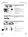
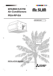
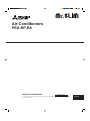
Air-Conditioners
PEA-RP·EA
INSTALLATION MANUAL
FOR INSTALLER
For safe and correct use, read this manual and the outdoor unit installation manual thoroughly before installing
the air-conditioner unit.
English
Contents
1.
2.
3.
4.
5.
Safety precautions ...................................................................................
Installation location ..................................................................................
Installing the indoor unit ...........................................................................
Installing the refrigerant piping .................................................................
Drainage piping work (Fig. 5-1) ................................................................
2
3
3
5
6
6.
7.
8.
9.
Electrical work .......................................................................................... 6
Duct work (Fig. 7-1) ............................................................................... 10
Test run .................................................................................................. 10
Easy maintenance function .................................................................... 13
1. Safety precautions
s Before installing the unit, make sure you read all the “Safety precautions”.
s Please report to or take consent by the supply authority before connection to the system.
Warning:
Describes precautions that must be observed to prevent danger of injury or
death to the user.
Caution:
Describes precautions that must be observed to prevent damage to the unit.
Warning:
• The unit must not be installed by the user. Ask a dealer or an authorized
technician to install the unit. If the unit is installed incorrectly, water leakage,
electric shock, or fire may result.
• For installation work, follow the instructions in the Installation Manual and
use tools and pipe components specifically made for use with R410A refrigerant. The R410A refrigerant in the HFC system is pressurized 1.6 times the
pressure of usual refrigerants. If pipe components not designed for R410A
refrigerant are used and the unit is not installed correctly, the pipes may burst
and cause damage or injuries. In addition, water leakage, electric shock, or
fire may result.
• The unit must be installed according to the instructions in order to minimize
the risk of damage from earthquakes, typhoons, or strong winds. An incorrectly installed unit may fall down and cause damage or injuries.
• The unit must be securely installed on a structure that can sustain its weight.
If the unit is mounted on an unstable structure, it may fall down and cause
damage or injuries.
• If the air conditioner is installed in a small room, measures must be taken to
prevent the refrigerant concentration in the room from exceeding the safety
limit in the event of refrigerant leakage. Consult a dealer regarding the appropriate measures to prevent the allowable concentration from being exceeded.
Should the refrigerant leak and cause the concentration limit to be exceeded,
hazards due to lack of oxygen in the room may result.
• Ventilate the room if refrigerant leaks during operation. If refrigerant comes
into contact with a flame, poisonous gases will be released.
• All electric work must be performed by a qualified technician according to
local regulations and the instructions given in this manual. The units must be
powered by dedicated power lines and the correct voltage and circuit breakers must be used. Power lines with insufficient capacity or incorrect electrical work may result in electric shock or fire.
After installation work has been completed, explain the “Safety Precautions,” use,
and maintenance of the unit to the customer according to the information in the Operation Manual and perform the test run to ensure normal operation. Both the Installation Manual and Operation Manual must be given to the user for keeping. These
manuals must be passed on to subsequent users.
: Indicates a part which must be grounded.
Warning:
Carefully read the labels affixed to the main unit.
• Use C1220 copper phosphorus, for copper and copper alloy seamless pipes,
to connect the refrigerant pipes. If the pipes are not connected correctly, the
unit will not be properly grounded and electric shock may result.
• Use only specified cables for wiring. The connections must be made securely
without tension on the terminals. If the cables are connected or installed incorrectly, overheating or fire may result.
• The terminal block cover of the outdoor unit must be firmly attached. If the
cover is mounted incorrectly and dust and moisture enter the unit, electric
shock or fire may result.
• When installing or moving the air conditioner, use only the specified refrigerant (R410A) to charge the refrigerant lines. Do not mix it with any other refrigerant and do not allow air to remain in the lines. Air enclosed in the lines can
cause pressure peaks resulting in a rupture and other hazards.
• Use only accessories authorized by Mitsubishi Electric and ask a dealer or
an authorized technician to install them. If accessories are incorrectly installed, water leakage, electric shock, or fire may result.
• Do not alter the unit. Consult a dealer for repairs. If alterations or repairs are
not performed correctly, water leakage, electric shock, or fire may result.
• The user should never attempt to repair the unit or transfer it to another location. If the unit is installed incorrectly, water leakage, electric shock, or fire
may result. If the air conditioner must be repaired or moved, ask a dealer or
an authorized technician.
• After installation has been completed, check for refrigerant leaks. If refrigerant leaks into the room and comes into contact with the flame of a heater or
portable cooking range, poisonous gases will be released.
1.1. Before installation
Caution:
• Do not use the unit in an unusual environment. If the air conditioner is installed in areas exposed to steam, volatile oil (including machine oil), or sulfuric
gas, areas exposed to high salt content such as the seaside, or areas where
the unit will be covered by snow, the performance can be significantly reduced and the internal parts can be damaged.
• Do not install the unit where combustible gases may leak, be produced, flow,
or accumulate. If combustible gas accumulates around the unit, fire or explosion may result.
• Do not keep food, plants, caged pets, artwork, or precision instruments in the
direct airflow of the indoor unit or too close to the unit, as these items can be
damaged by temperature changes or dripping water.
• When the room humidity exceeds 80% or when the drainpipe is clogged, water may drip from the indoor unit. Do not install the indoor unit where such
dripping can cause damage. The outdoor unit produces condensation during
the heating operation. Make sure to provide drainage around the outdoor unit
if such condensation is likely to cause damage.
• When installing the unit in a hospital or communications office, be prepared
for noise and electronic interference. Inverters, home appliances, high-frequency medical equipment, and radio communications equipment can cause
the air conditioner to malfunction or breakdown. The air conditioner may also
affect medical equipment, disturbing medical care, and communications equipment, harming the screen display quality.
1.2. Before installation (relocation)
Caution:
• Be extremely careful when transporting the units. Two or more persons are
needed to handle the unit, as it weighs 20 kg or more. Do not grasp the packaging bands. Wear protective gloves to remove the unit from the packaging
and to move it, as you can injure your hands on the fins or other parts.
• Be sure to safely dispose of the packaging materials. Packaging materials,
such as nails and other metal or wooden parts may cause stabs or other
injuries.
• Thermal insulation of the drainpipe is necessary to prevent condensation. If
the drainpipe is not properly insulated, condensation will be formed and the
ceiling, floor, or important items may be damaged.
2
• Install the drainpipe according to this Installation Manual to ensure proper
drainage. Place thermal insulation on the pipes to prevent condensation. If
the drainpipe is installed incorrectly, water leakage and damage to the ceiling, floor, furniture, or other possessions may result.
• The base and attachments of the outdoor unit must be periodically checked
for looseness, cracks or other damage. If such defects are left uncorrected,
the unit may fall down and cause damage or injuries.
• Do not clean the air conditioner unit with water. Electric shock may result.
• Tighten all flare nuts to specification using a torque wrench. If tightened too
much, the flare nut can break after an extended period and refrigerant can
leak out.
1. Safety precautions
1.3. Before electric work
Caution:
• Be sure to install circuit breakers. If not installed, electric shock may result.
• For the power lines, use standard cables of sufficient capacity. Otherwise, a
short circuit, overheating, or fire may result.
• When installing the power lines, do not apply tension to the cables. If the
connections are loosened, the cables can snap or break and overheating or
fire may result.
• Be sure to ground the unit. Do not connect the ground wire to gas or water
pipes, lighting rods, or telephone grounding lines. If the unit is not properly
grounded, electric shock may result.
• Use circuit breakers (ground fault interrupter, isolating switch (+B fuse), and
molded case circuit breaker) with the specified capacity. If the circuit breaker
capacity is larger than the specified capacity, breakdown or fire may result.
1.4. Before starting the test run
Caution:
• Turn on the main power switch more than 12 hours before starting operation.
Starting operation just after turning on the power switch can severely damage the internal parts. Keep the main power switch turned on during the operation season.
• Before starting operation, check that all panels, guards and other protective
parts are correctly installed. Rotating, hot, or high voltage parts can cause
injuries.
• Do not operate the air conditioner without the air filter set in place. If the air
filter is not installed, dust may accumulate and breakdown may result.
• Do not touch any switch with wet hands. Electric shock may result.
• Do not touch the refrigerant pipes with bare hands during operation. The
refrigerant pipes are hot or cold depending on the condition of the flowing
refrigerant. If you touch the pipes, burns or frostbite may result.
• After stopping operation, be sure to wait at least five minutes before turning
off the main power switch. Otherwise, water leakage or breakdown may result.
2. Installation location
•
•
•
•
•
•
Select a location so that air can be blown into all corners of the room.
Avoid locations exposed to outside air.
Select a location free of obstructions to the airflow in and out of the unit.
Avoid locations exposed to steam or oil vapour.
Avoid locations where combustible gas may leak, settle or be generated.
Avoid installation near machines emitting high-frequency waves (high-frequency
welders, etc.)
• Avoid locations where the airflow is directed at a fire alarm sensor. (Hot air could
trigger the alarm during the heating operation.)
• Avoid places where acidic solutions are frequently handled.
• Avoid places where sulphur-based or other sprays are frequently used.
• Must be installed at least 1.8 m above floor or grade level.
Warning:
The unit must be securely installed on a structure that can sustain its weight.
3. Installing the indoor unit
1
2
3.1. Check the indoor unit accessories (Fig. 3-1)
The indoor unit is provided with the following accessories.
1
2
3
Accessory name
Pipe cover (for refrigerant piping joint)
small diameter
large diameter
Band
Remote controller
Q’ty
1
1
4
1
3
Fig. 3-1
3
3. Installing the indoor unit
D
(mm)
W
A
B
C
D
E
H
21
11
Air intake
Air outlet
Service space
Drain pan
Electrical parts box
Models
W
RP71
785
RP100
1055
RP125
1255
RP140
1415
*B : Suspension bolt pitch
200
200
3.2. Unit dimension and service space (Fig. 3-2)
11
H
690
690
690
690
D
428
428
428
428
A
650
920
1120
1306
(mm)
B
690
960
1160
1346
B
A
A
D
100
600
B
300
530
E
C
900
Fig. 3-2
1
2
20
0
3.3. Suspension structure (Give site of suspension
strong structure) (Fig. 3-3)
G
• The ceiling work differs according to the construction of the building. Building constructors and interior decorators should be consulted for details.
B
E
A
B
F
C D
A
B
C
D
E Use inserts rated at 100-150 kg each
(procure locally)
F Suspension bolts M10 (3/8") (procure
locally)
G Steel reinforcing rod
Ceiling
Rafter
Beam
Roof beam
Fig. 3-3
130
D
E
Suspend the main unit as shown in the Fig. 3-4.
1 When no air intake duct flange is used.
2 When air intake duct flange is used.
D
E
C
A Washer (procure locally)
B 2 nuts (procure locally)
C Suspension bolt (procure locally)
D Air intake
E Air outlet
F Air intake duct flange
Fig. 3-4
4
3.4. Unit suspension procedures (Fig. 3-4)
30
A
B
100
2
30
1
1 Wooden structures
• Use tie beams (single storied houses) or second floor beams
(mm)
(two story houses) as reinforcing members.
Models
B
• Wooden beams for suspending air conditioners must be
RP71
690
sturdy and their sides must be at least 6 cm long if the
RP100
960
beams are separated by not more than 90 cm and their
RP125
1160
sides must be at least 9 cm long if the beams are sepaRP140
1346
rated by as much as 180 cm. The size of the suspension
bolts should be ø10 (3/8"). (The bolts do not come with the
unit.)
2 Ferro-concrete structures
Secure the suspension bolts using the method shown, or use steel or wooden hangers, etc. to install the suspension bolts.
F
Caution:
• Make sure that the unit is level when installed.
• Work with the protection gloves when you install the unit. (Take care of a
hurt.)
To prevent getting hurt.
4. Installing the refrigerant piping
4.1. Precautions
4.1.2. For devices that use R410A refrigerant
4.1.1. For devices that use R407C refrigerant
• Use ester oil, ether oil, alkylbenzene oil (small amount) as the refrigeration oil
applied to the flared sections.
• Use C1220 copper phosphorus, for copper and copper alloy seamless pipes,
to connect the refrigerant pipes. Use refrigerant pipes with the thicknesses
specified in the table to the below. Make sure the insides of the pipes are
clean and do not contain any harmful contaminants such as sulfuric compounds, oxidants, debris, or dust.
• Do not use the existing refrigerant piping.
• Do not use crushed, misshapen, or discolored tubing. The inside of the tubing should be clean and free from harmful sulfuric compounds, oxidants,
dirt, debris, oils and moisture.
• Store the piping to be used during installation indoors and keep both ends of
the piping sealed until just before brazing.
• Use ester oil, ether oil or alkylbenzene (small amount) as the refrigerator oil
to coat flares and flange connections.
• Use liquid refrigerant to fill the system.
• Do not use a refrigerant other than R407C.
• Use a vacuum pump with a reverse flow check valve.
• Do not use the tools that are used with conventional refrigerants.
• Do not use a charging cylinder.
• Be especially careful when managing the tools.
• Do not use commercially available dryers.
Warning:
When installing or moving the air conditioner, use only the specified refrigerant (R410A) to charge the refrigerant lines. Do not mix it with any other refrigerant and do not allow air to remain in the lines. Air enclosed in the lines can
cause pressure peaks resulting in a rupture and other hazards.
Liquid pipe
Gas pipe
RP71-140
ø9.52 thickness 0.8 mm
ø15.88 thickness 1.0 mm
• Do not use pipes thinner than those specified above.
A
øA
.8
R0
.4~
R0
90° ±0.5°
4.2. Indoor unit (Fig. 4-1)
B
45°±2°
Apply refrigerating machine oil over the entire flare seat surface.
Be sure to only use the flare nuts
that came with the unit.
Fig. 4-1
Available pipe size
RP71
RP100, 125, 140
–
–
ø9.52
ø9.52
–
–
Gas side
ø15.88
ø15.88
–
–
: Factory flare nut attachment to the heat-exchanger.
Liquid side
B Flare nut tightening torque
A Flare cutting dimensions
Copper pipe O.D.
(mm)
ø6.35
ø9.52
ø12.7
ø15.88
ø19.05
• When commercially available copper pipes are used, wrap liquid and gas pipes
with commercially available insulation materials (heat-resistant to 100 °C or more,
thickness of 12 mm or more).
• The indoor parts of the drain pipe should be wrapped with polyethylene foam insulation materials (specific gravity of 0.03, thickness of 9 mm or more).
• Apply thin layer of refrigerant oil to pipe and joint seating surface before tightening
flare nut.
• Use two wrenches to tighten piping connections.
• Use leak detector or soapy water to check for gas leaks after connections are completed.
• Use refrigerant piping insulation provided to insulate indoor unit connections. Insulate carefully following shown below.
• Use correct flare nuts meeting the pipe size of the outdoor unit.
Flare dimensions
øA dimensions (mm)
8.7 - 9.1
12.8 - 13.2
16.2 - 16.6
19.3 - 19.7
23.6 - 24.0
Copper pipe O.D.
(mm)
ø6.35
ø6.35
ø9.52
ø12.7
ø12.7
ø15.88
ø15.88
ø19.05
Flare nut O.D.
(mm)
17
22
22
26
29
29
36
36
Tightening torque
(N·m)
14 - 18
34 - 42
34 - 42
49 - 61
68 - 82
68 - 82
100 - 120
100 - 120
A
A Die
B Copper pipe
A
B
Fig. 4-2
Copper pipe O.D.
(mm)
ø6.35 (1/4")
ø9.52 (3/8")
ø12.7 (1/2")
ø15.88 (5/8")
ø19.05 (3/4")
A (mm)
Flare tool for R-22·R407C
Flare tool for R410A
Clutch type
0 - 0.5
1.0 - 1.5
0 - 0.5
1.0 - 1.5
0 - 0.5
1.0 - 1.5
0 - 0.5
1.0 - 1.5
0 - 0.5
1.0 - 1.5
5
4. Installing the refrigerant piping
E
4.3. Refrigerant and drainage piping locations of indoor
unit (Fig. 4-3)
E
A
B
C
D
E
A
B
D
C
C
Fig. 4-3
F
4.4. Refrigerant piping (Fig. 4-4)
G
BC
F
B,C
J
I
A
H
D
E
Fig. 4-4
Refrigerant pipe (gas)
Refrigerant pipe (liquid)
Drain pipe
Air filter (option)
Ceiling
A Refrigerant pipe and insulating material
B Pipe cover (large)
C Pipe cover (small)
D Refrigerant pipe (gas)
E Refrigerant pipe (liquid)
F Band
G Cross-sectional view of connection
H Pipe
I Insulating material
J Squeeze
Heat insulation for refrigerant pipes:
1 Wrap the enclosed large-sized pipe cover around the gas pipe, making sure that
the end of the pipe cover touches the side of the unit.
2 Wrap the enclosed small-sized pipe cover around the liquid pipe, making sure
that the end of the pipe cover touches the side of the unit.
3 Secure both ends of each pipe cover with the enclosed bands. (Attach the bands
20 mm from the ends of the pipe cover.)
• After connecting the refrigerant piping to the indoor unit, be sure to test the pipe
connections for gas leakage with nitrogen gas. (Check that there is no refrigerant
leakage from the refrigerant piping to the indoor unit.)
Conduct the airtightness test before connecting the outdoor unit stop valve and the
refrigerant pipe.
If the test is conducted after the valve and pipe are connected, gas, which is used
for checking the airtightness, will leak from the stop valve and flow into the outdoor
unit, resulting in abnormal operation.
4.5. For twin/triple combination
Refer to the outdoor unit installation manual.
5. Drainage piping work (Fig. 5-1)
B
H1
A
H2
C
A Indoor unit
B Trap
C Drainge piping connection 1RP male
H1: 50 mm or more
H2: 1/2 H1 or more
• The drainage pipe should be arranged so that the discharge end is lower than the
other end, as shown in the figure opposite.
• Place the trap outside the unit.
• After connecting the drainage pipe, make sure that water is discharged properly
and that there are no leaks.
Fig. 5-1
6. Electrical work
D
(mm)
6.1. Indoor unit
F
1. Remove the two electrical parts cover (2 screws). (Fig. 6-1)
A
B
C
D
E
F
A
B
C
Electrical parts cover
Knockout holes
Terminal bed (Indoor/Outdoor unit)
Terminal bed (Remote controller)
Indoor contoroller board
Indoor/Power board
E
Fig. 6-1
2. Open knockout holes. (Fig. 6-2)
(Recommend to use a screwdriver or the like for this work.)
A
A
B
C
D
E
B
F
G
H
C
I
D
Fig. 6-2
Fig. 6-3
Control box
Knockout hole
Remove
Knockout hole
3. Wire the Indoor/Outdoor connecting cables with buffer bushing for tensile force.
(PG connection or the like) Wire the remote controller cables using ordinary bushing. (Fig. 6-3)
• Install the earth cable, longer than other cables. (The earth cable dia. :Thicker
than 1.6 mm)
E Knockout hole for the Indoor/Outdoor connecting cable.
Use buffer bushing to prevent tensile force to the terminal bed.
F The Indoor/Outdoor connecting cables
G Tensile force
H Knockout hole for the remote controller cables. Use ordinary bushing.
I The remote controller cables
s Selecting non-fuse breaker (NF) or earth leakage breaker (NV).
6
6. Electrical work
6.2. Indoor unit power supplied from outdoor unit
The following connection patterns are available.
The outdoor unit power supply patterns vary on models.
1:1 System
<For models without heater>
<For models with heater>
G
D
A
B
C
D
L
N
A
B
C
L
N
G
H
B
L
N
C
S1
S1
S1
S1
S2
S2
S2
S2
S3
S3
S3
S3
E
F
E
F
1
2
A
B
C
D
E
F
G
H
Outdoor unit power supply
Earth leakage breaker
Wiring circuit breaker or isolating switch
Outdoor unit
Indoor unit/outdoor unit connecting cords
Remote controller
Indoor unit
Heater power supply
A
B
C
D
E
F
G
H
Outdoor unit power supply
Earth leakage breaker
Wiring circuit breaker or isolating switch
Outdoor unit
Indoor unit/outdoor unit connecting cords
Remote controller
Indoor unit
Heater power supply
1
2
* Affix a label A that is included with the manuals near each wiring diagram for the indoor and outdoor units.
Simultaneous twin/triple/four system
<For models without heater>
<For models with heater>
G
D
A
B
C
G
G
G
L
N
A
B
C
D
G
G
G
L
N
L
N
L
N
L
N
H
B
C
S1
S1
S1
S1
S1
S1
S1
S1
S1
S2
S2
S2
S2
S2
S2
S2
S2
S2
S3
S3
S3
S3
S3
S3
S3
S3
S3
1
2
1
2
1
2
E
F
E
F
1
2
1
2
1
2
1
2
* Affix a label A that is included with the manuals near each wiring diagram for the indoor and outdoor units.
Circuit
rating
Wiring
Wire No. × size
(mm2)
Indoor unit model
Indoor unit power supply (Heater)
Indoor unit input capacity (Heater)
Main switch (Breaker)
Indoor unit power supply (Heater)
Indoor unit power supply (Heater) earth
Indoor unit-Outdoor unit
Indoor unit-Outdoor unit earth
Remote controller-Indoor unit
Indoor unit (Heater) L-N
Indoor unit-Outdoor unit S1-S2
Indoor unit-Outdoor unit S2-S3
Remote controller-Indoor unit
PEA
–
*1
–
*2
*2
*3
*4
*4
*4
*4
–
–
3 × 1.5 (polar)
1 × Min.1.5
2 × 0.3 (Non-polar)
–
AC 230 V
DC24 V
DC12 V
*1. A breaker with at least 3 mm contact separation in each pole shall be provided. Use non-fuse breaker (NF) or earth leakage breaker (NV).
*2. <For 25-140 outdoor unit application>
Max. 45 m
If 2.5 mm2 used, Max. 50 m
If 2.5 mm2 used and S3 separated, Max. 80 m
For PUHZ-RP100/125/140 YHA application, use shield wires. The shield part must be grounded with the indoor unit OR the outdoor unit, NOT with both.
<For 200/250 outdoor unit application>
Max. 18 m
If 2.5 mm2 used, Max. 30 m
If 4 mm2 used and S3 separated, Max. 50 m
If 6 mm2 used and S3 separated, Max. 80 m
*3. The 10 m wire is attached in the remote controller accessory. Max. 500 m
*4. The figures are NOT always against the ground.
S3 terminal has DC 24 V against S2 terminal. However between S3 and S1, these terminals are not electrically insulataed by the transformer or other device.
Notes: 1. Wiring size must comply with the applicable local and national code.
2. Power supply cords and indoor unit/outdoor unit connecting cords shall not be lighter than polychloroprene sheathed flexible cord. (Design 245 IEC 57)
3. Install an earth longer than other cables.
7
6. Electrical work
6.3. Separate indoor unit/outdoor unit power supplies (For PUHZ application only)
The following connection patterns are available.
The outdoor unit power supply patterns vary on models.
1:1 System
<For models without heater>
* The indoor power supply terminal kit is required.
G
D
B
A
L
N
C
J
S1
S2
S3
B
L
N
C
H
S1
S2
S3
E
1
2
F
A
B
C
D
E
F
G
H
J
Outdoor unit power supply
Earth leakage breaker
Wiring circuit breaker or isolating switch
Outdoor unit
Indoor unit/outdoor unit connecting cords
Remote controller
Indoor unit
Option
Indoor unit power supply
A
B
C
D
E
F
G
H
J
Outdoor unit power supply
Earth leakage breaker
Wiring circuit breaker or isolating switch
Outdoor unit
Indoor unit/outdoor unit connecting cords
Remote controller
Indoor unit
Option
Indoor unit power supply
* Affix a label B that is included with the manuals near each wiring diagram for the indoor and outdoor units.
Simultaneous twin/triple/four system
<For models without heater>
* The indoor power supply terminal kits are required.
A
B
C
D
G
G
G
G
L
N
L
N
L
N
L
N
L
N
S1
S2
S3
S1
S2
S3
S1
S2
S3
S1
S2
S3
1
2
1
2
1
2
1
2
J
S1
S2
S3
B
C
E
F
H
* Affix a label B that is included with the manuals near each wiring diagram for the indoor and outdoor units.
If the indoor and outdoor units have separate power supplies, refer to the table at the
below. If the optional wiring replacement kit is used, change the indoor unit electrical
box wiring refering to the figure in the right and the DIP switch settings of the outdoor
unit control board.
Indoor unit specifications
Required
Electric heater
(For models with
heater)
L
N
Required
2
Electric heater
(For models with
heater)
Indoor unit power supplied from outdoor unit
(when shipped from factory)
3
1
ORANGE
CND
Indoor unit
control board
(SW8)
If the indoor and
outdoor units have
separate power
supplies, change the
connections of the
connectors as shown
in the following
figure.
L
N
CND
S1
S2
S3
* There are three types of labels (labels A, B, and C). Affix the appropriate labels to
the units according to the wiring method.
Connectors
BLUE YELLOW
YELLOW BLUE
ON
OFF
S1
S2
S3
CND
Required
BLUE YELLOW
BLUE YELLOW
Indoor power supply terminal kit (option)
Indoor unit electrical box connector connection change
Label affixed near each wiring diagram
for the indoor and outdoor units
Outdoor unit DIP switch settings (when
using separate indoor unit/outdoor unit
power supplies only)
Connectors (connections when shipped
from the factory are for indoor unit power
supplied from outdoor unit)
ORANGE
CND
Indoor unit
control board
Separate indoor unit/outdoor unit power
supplies
Circuit
rating
Wiring
Wire No. × size
(mm2)
Indoor unit model
Indoor unit power supply
Indoor unit input capacity
Main switch (Breaker)
Indoor unit power supply
Indoor unit power supply earth
Indoor unit-Outdoor unit
Indoor unit-Outdoor unit earth
Remote controller-Indoor unit
Indoor unit L-N
Indoor unit-Outdoor unit S1-S2
Indoor unit-Outdoor unit S2-S3
Remote controller-Indoor unit
PEA
~/N (single), 50 Hz, 230 V
*1
*2
*3
*4
*4
*4
*4
16 A
2 × Min. 1.5
1 × Min. 1.5
2 × Min. 0.3
–
2 × 0.3 (Non-polar)
AC 230 V
–
DC24 V
DC12 V
*1. A breaker with at least 3 mm contact separation in each pole shall be provided. Use non-fuse breaker (NF) or earth leakage breaker (NV).
*2. Max. 120 m
For PUHZ-RP100/125/140 YHA application, use shield wires. The shield part must be grounded with the indoor unit OR the outdoor unit, NOT with both.
*3. The 10 m wire is attached in the remote controller accessory. Max. 500 m
*4. The figures are NOT always against the ground.
Notes: 1. Wiring size must comply with the applicable local and national code.
2. Power supply cords and indoor unit/outdoor unit connecting cords shall not be lighter than polychloroprene sheathed flexible cord. (Design 245 IEC 57)
3. Install an earth longer than other cables.
8
6. Electrical work
B
6.4. Remote controller (Wired remote controller)
A
30
1) Installing procedures
(1) Select an installing position for the remote controller. (Fig. 6-4)
The temperature sensors are located on both remote controller and indoor unit.
s Procure the following parts locally:
Two piece switch box
Thin copper conduit tube
Lock nuts and bushings
30
30
83.5
46
C
A
E
F
I
G
H
120
C
D
Fig. 6-4
B-1.
B-2.
B
H
H
I
J
A Remote controller profile
B Required clearances surrounding the remote controller
C Installation pitch
(2) Seal the service entrance for the remote controller cord with putty to prevent possible invasion of dew drops, water, cockroaches or worms. (Fig. 6-5)
A For installation in the switch box:
B For direct installation on the wall select one of the following:
• Prepare a hole through the wall to pass the remote controller cord (in order to run
the remote controller cord from the back), then seal the hole with putty.
• Run the remote controller cord through the cut-out upper case, then seal the cutout notch with putty similarly as above.
B-1. To lead the remote controller cord from the back of the controller:
B-2. To run the remote controller cord through the upper portion:
(3) For direct installation on the wall
C
D
E
F
G
H
I
J
I
Fig. 6-5
A
Wall
Conduit
Lock nut
Bushing
Switch box
Remote controller cord
Seal with putty
Wood screw
2) Connecting procedures (Fig. 6-6)
1 Connect the remote controller cord to the terminal block.
A To TB5 on the indoor unit
B TB6 (No polarity)
AB
3) Two remote controllers setting
If two remote controllers are connected, set one to “Main” and the other to “Sub”. For
setting procedures, refer to “Function selection of remote controller” in the operation
manual for the indoor unit.
TB6
B
Fig. 6-6
2
6.5. Function settings (Wired remote controller) (Fig. 6-7)
3 4
1
⁄
2
⁄
3
⁄
4
⁄
1
TEMP.
F
MENU
E
G
BACK
PAR-21MAA
MONITOR/SET
ON/OFF
ON/OFF
FILTER
DAY
CLOCK
C
A
CHECK TEST
OPERATION
CLEAR
B
D
4
1
1
2
Mode number
Setting number
Refrigerant address
Unit number
Changing the power voltage setting
• Be sure to change the power voltage setting depending on the voltage used.
1 Go to the function setting mode.
Switch OFF the remote controller.
Press the A and B buttons simultaneously and hold them for at least 2
seconds. FUNCTION will start to flash.
2 Use the C button to set the refrigerant address (3) to 00.
3 Press D and [--] will start to flash in the unit number (4) display.
4 Use the C button to set the unit number (4) to 00.
5 Press the E MODE button to designate the refrigerant address/unit number. [--]
will flash in the mode number (1) display momentarily.
6 Press the F buttons to set the mode number (1) to 04.
7 Press the G button and the current set setting number (2) will flash.
Use the F button to switch the setting number in response to the power supply
voltage to be used.
Power supply voltage
240 V
: setting number = 1
220 V, 230 V : setting number = 2
8 Press the MODE button E and mode and the setting number (1) and (2) will
change to being on constantly and the contents of the setting can be confirmed.
9 Press the FILTER A and TEST RUN B buttons simultaneously for at least two
seconds. The function selection screen will disappear momentarily and the air
conditioner OFF display will appear.
Fig. 6-7
Function table
Select unit number 00
Mode
Power failure automatic recovery
Indoor temperature detecting
LOSSNAY connectivity
Power voltage
Auto mode (only for PUHZ)
Settings
Not available
Available
*1
Indoor unit operating average
Set by indoor unit’s remote controller
Remote controller’s internal sensor
Not Supported
Supported (indoor unit is not equipped with outdoor-air intake)
Supported (indoor unit is equipped with outdoor-air intake)
240 V
220 V, 230 V
Energy saving cycle automatically enabled
Energy saving cycle automatically disabled
Mode no.
01
02
03
04
05
Setting no. Initial setting
1
*2
2
*2
1
2
3
1
2
3
1
2
1
2
setting
9
6. Electrical work
Select unit numbers 01 to 03 or all units (AL [wired remote controller]/07 [wireless remote controller])
Settings
Mode
100Hr
Filter sign
2500Hr
No filter sign indicator
Standard (PLH/PLA)/Silent (PCH/PCA)
Fan speed
High ceiling 1 (PLH/PLA)/Standard (PCH/PCA)
High ceiling 2 (PLH/PLA)/High ceiling (PCH/PCA)
No. of air outlets
4 directions
3 directions
2 directions
Installed options (high-performance filter)
Not supported
Supported
Up/down vane setting
No vanes
Equipped with vanes (vanes angle setup 1)
Equipped with vanes (vanes angle setup 2)
Energy saving air flow
Disabled
(Heating mode)
Enabled
Mode no.
07
08
09
10
11
12
Setting no. Initial setting
1
2
3
1
2
–
3
1
2
–
3
1
–
2
1
2
–
3
1
–
2
setting
*1 When the power supply returns, the air conditioner will start 3 minutes later.
*2 Power failure automatic recovery initial setting depends on the connecting outdoor unit.
7. Duct work (Fig. 7-1)
B
E
D
M
M
N
L
A
K
J
I
C
F
G
H
A
B
C
D
E
F
G
H
I
J
K
L
M
N
O
Indoor unit
Air intake duct flange
Drain pan
Air outlet duct flange
Electrical parts box
Air intake
Air outlet
Leave clearance to prevent
short cycle
Ceiling
Air intake (procure locally)
Air filter (procure locally)
Air intake duct (procure locally)
Canvas duct (procure locally)
Air outlet duct (procure locally)
Air outlet grille (procure locally)
Use the canvas duct for connecting the indoor unit and the duct.
Use fire-proof material for the duct parts.
Make sure that the duct has sufficient heat insulation.
Notes:
• An outlet duct of 850 mm or more is needed for construction.
• Connect the main body of the air conditioner and the duct so that their
potentials are equal.
• The standard external static pressure should be 125 Pa.
• Connect an earth cable R from the air intake duct E to the earth terminal Q.
Then, connect another earth cable R from the earth terminal Q to the air
outlet duct F.
Fig. 7-1
8. Test run
8.1. Before test run
s After completing installation and the wiring and piping of the indoor and outdoor
units, check for refrigerant leakage, looseness in the power supply or control
wiring, wrong polarity, and no disconnection of one phase in the supply.
s Use a 500-volt megohmmeter to check that the resistance between the power
Ω.
supply terminals and ground is at least 1.0MΩ
s Do not carry out this test on the control wiring (low voltage circuit) terminals.
Warning:
Ω.
Do not use the air conditioner if the insulation resistance is less than 1.0MΩ
Insulation resistance
After installation or after the power source to the unit has been cut for an extended
period, the insulation resistance will drop below 1 MΩ due to refrigerant accumulating in the compressor. This is not a malfunction. Perform the following procedures.
1. Remove the wires from the compressor and measure the insulation resistance of
the compressor.
2. If the insulation resistance is below 1 MΩ, the compressor is faulty or the resistance dropped due the accumulation of refrigerant in the compressor.
3. After connecting the wires to the compressor, the compressor will start to warm
up after power is supplied. After supplying power for the times indicated below,
measure the insulation resistance again.
• The insulation resistance drops due to accumulation of refrigerant in the compressor. The resistance will rise above 1 MΩ after the compressor is warmed
up for two to three hours.
(The time necessary to warm up the compressor varies according to atmospheric conditions and refrigerant accumulation.)
• To operate the compressor with refrigerant accumulated in the compressor,
the compressor must be warmed up at least 12 hours to prevent breakdown.
4. If the insulation resistance rises above 1 MΩ, the compressor is not faulty.
Caution:
• The compressor will not operate unless the power supply phase connection
is correct.
• Turn on the power at least 12 hours before starting operation.
• Starting operation immediately after turning on the main power switch can
result in severe damage to internal parts. Keep the power switch turned on
during the operational season.
10
s The followings must be checked as well.
• The outdoor unit is not faulty. LED1 and LED2 on the control board of the outdoor
unit flash when the outdoor unit is faulty.
• Both the gas and liquid stop valves are completely open.
• A protective sheet covers the surface of the DIP switch panel on the control board of
the outdoor unit. Remove the protective sheet to operate the DIP switches easily.
• Make sure that the all of the SW5 DIP switches for function changes on the control
board of the outdoor unit are set to OFF. If all of the SW5 switches are not set to
OFF, record the settings and then set all of the switches to OFF. Begin recovering
the refrigerant. After moving the unit to a new location and completing the test run,
set the SW5 switches to the previously recorded settings.
Unit replacement operation
s When reusing existing pipes that carried R22 refrigerant, replacement operation must be performed before performing a test run.
• If new pipes are used, these procedures are not necessary.
• If existing pipes that carried R22 refrigerant are used for the RP3 model, these
procedures are not necessary. (The replacement operation cannot be performed.)
Replacement operation procedures
1 Supply power.
2 Set DIP switch SW8-2 on the control board of the outdoor unit to ON to start
replacement operation.
* The replacement operation is performed using the cooling system. Cool air will
flow from the indoor unit during the replacement operation.
* During the replacement operation, TEST RUN is displayed on the remote controller
and LED1 and LED2 on the control board of the outdoor unit flash together.
3 Replacement operation requires at least two hours to complete.
* After setting switch SW8-2 to ON, the unit automatically stops after two hours.
* Replacement operation can be performed repeatedly by setting switch SW8-2
from OFF to ON. Wait at least two hours before starting replacement operation.
(If operation is started in less than two hours, the existing pipes will not be
cleaned and the unit may be damaged.)
4 Set switch SW8-2 to OFF. (Replacement operation is complete.)
* If the indoor temperature is less than 15°C, the compressor will operate intermittently but the unit is not faulty.
8. Test run
F E
A ON/OFF button
B Test run display
C Indoor temperature liquid line
temperature display
D ON/OFF lamp
E Power display
F Error code display
Test run remaining time display
G Set temperature button
H Mode selection button
I Fan speed button
M TEST button
D B
TEST RUN
COOL, HEAT
C
˚C
˚C
SIMPLE
TEMP.
MENU
BACK
ON/OFF
CHECK TEST
OPERATION
CLOCK
A
FILTER
DAY
MONITOR/SET
PAR-21MAA
ON/OFF
CLEAR
8.2. Test run
The following 2 methods are available.
8.2.1. Using wired remote controller (Fig. 8-1)
1
2
3
4
5
6
7
8
I M
Fig. 8-1
HG
Turn on the power at least 12 hours before the test run.
Press the [TEST] button twice. ➡ “TEST RUN” liquid crystal display
Press the [Mode selection] button. ➡ Make sure that wind is blown out.
Press the [Mode selection] button and switch to the cooling (or heating) mode.
➡ Make sure that cold (or warm) wind is blown out.
Press the [Fan speed] button. ➡ Make sure that the wind speed is switched.
Check operation of the outdoor unit fan.
Release test run by pressing the [ON/OFF] button. ➡ Stop
Register a telephone number.
The telephone number of the repair shop, sales office, etc., to contact if an error
occurs can be registered in the remote controller. The telephone number will be
displayed when an error occurs. For registration procedures, refer to the operation
manual for the indoor unit.
8.2.2. Using SW4 in outdoor unit
Refer to the outdoor unit installation manual.
8.3. Self-check (Wired remote controller) (Fig. 8-2)
E D
B
1
2
3
4
ERROR CODE
B
E
Turn on the power.
Press the [CHECK] button twice.
Set refrigerant address with [TEMP] button if system control is used.
Press the [ON/OFF] button to stop the self-check.
ERROR CODE
TEMP.
A
B
C
D
CHECK button
Refrigerant address
TEMP. button
IC: Indoor unit
OC: Outdoor unit
E Check code
F Unit address
ON/OFF
C
ERROR CODE
MENU
BACK
PAR-21MAA
MONITOR/SET
ON/OFF
FILTER
DAY
CHECK TEST
OPERATION
CLOCK
F
CLEAR
A
Fig. 8-2
• Refer to the following tables for details on the check codes. (Wireless remote controller)
[Output pattern A]
Beeper sounds
OPERATION
INDICATOR
lamp flash
pattern
Beep
Beep
Beep
Beep
Beep
Beep
1st
2nd
3rd
nth
1st
Beep
2nd · · · Repeated
Off
On
On
On
Off
On
On
On
0.5 sec. Approx. 2.5 sec. 0.5 sec. 0.5 sec.
Self-check Approx. 2.5 sec. 0.5 sec. 0.5 sec. 0.5 sec.
starts
(Start signal
Number of flashes/beeps in pattern indicates the check
Number of flashes/beeps in pattern indicates
received)
code in the following table (i.e., n=5 for “P5”)
the check code in the following table
[Output pattern B]
Beeper sounds
OPERATION
INDICATOR
lamp flash
pattern
Beep
Off
Self-check Approx. 2.5 sec.
starts
(Start signal
received)
[Output pattern A]
On
Approx. 3 sec.
Beep
Beep
Beep
Beep
Beep
1st
2nd
3rd
nth
1st
On
On
On
0.5 sec. 0.5 sec. 0.5 sec.
On
0.5 sec.
Off
Approx. 2.5 sec.
Number of flashes/beeps in pattern indicates the check
code in the following table (i.e., n=5 for “P5”)
On
Approx. 3 sec.
On
0.5 sec.
Beep
2nd · · · Repeated
On
0.5 sec.
Number of flashes/beeps in pattern indicates
the check code in the following table
Errors detected by indoor unit
Wireless remote controller
Beeper sounds/OPERATION
INDICATOR lamp flashes
(Number of times)
1
2
3
4
5
6
7
8
9
10
11
12
No sound
Wired remote
controller
Symptom
Remark
Check code
P1
P2, P9
E6, E7
P4
P5
P6
EE
P8
E4
–
–
Fb
––
Intake sensor error
Pipe (Liquid or 2-phase pipe) sensor error
Indoor/outdoor unit communication error
Drain sensor error
Drain pump error
Freezing/Overheating safeguard operation
Communication error between indoor and outdoor units
Pipe temperature error
Remote controller signal receiving error
–
–
Indoor unit control system error (memory error, etc.)
No corresponding
11
8. Test run
[Output pattern B]
Errors detected by unit other than indoor unit (outdoor unit, etc.)
Wireless remote controller
Wired remote
controller
Beeper sounds/OPERATION
INDICATOR lamp flashes
(Number of times)
1
2
3
4
5
6
7
8
9
10
11
Symptom
E9
UP
U3, U4
UF
U2
U1, Ud
U5
U8
U6
U7
U9, UH
12
13
14
–
–
Others
Remark
Check code
Indoor/outdoor unit communication error (Transmitting error) (Outdoor unit)
Compressor overcurrent interruption
Open/short of outdoor unit thermistors
Compressor overcurrent interruption (When compressor locked)
Abnormal high discharging temperature/49C worked/insufficient refrigerant
Abnormal high pressure (63H worked)/Overheating safeguard operation
Abnormal temperature of heat sink
Outdoor unit fan safeguard stop
Compressor overcurrent interruption/Abnormal of power module
Abnormality of super heat due to low discharge temperature
Abnormality such as overvoltage or voltage shortage and abnormal synchronous
signal to main circuit/Current sensor error
–
–
Other errors (Refer to the technical manual for the outdoor unit.)
For details, check the LED display
of the outdoor controller board.
*1 If the beeper does not sound again after the initial two beeps to confirm the self-check start signal was received and the OPERATION INDICATOR lamp does not come on,
there are no error records.
*2 If the beeper sounds three times continuously “beep, beep, beep (0.4 + 0.4 + 0.4 sec.)” after the initial two beeps to confirm the self-check start signal was received, the
specified refrigerant address is incorrect.
• On wired remote controller
Check code displayed in the LCD.
• If the unit cannot be operated properly after the above test run has been performed, refer to the following table to remove the cause.
Symptom
Wired remote controller
PLEASE WAIT
For about 2
minutes following
power-on
PLEASE WAIT → Error code
After about 2
minutes has
expired following
Display messages do not appear even power-on
when operation switch is turned ON
(operation lamp does not light up).
Cause
LED 1, 2 (PCB in outdoor unit)
After LED 1, 2 are lighted, LED 2 is turned off,
then only LED 1 is lighted. (Correct operation)
• For about 2 minutes following power-on, operation of the
remote controller is not possible due to system start-up. (Correct operation)
Only LED 1 is lighted. → LED 1, 2 blink.
• Connector for the outdoor unit’s protection device is not connected.
• Reverse or open phase wiring for the outdoor unit’s power
terminal block (L1, L2, L3)
Only LED 1 is lighted. → LED 1 blinks twice,
LED 2 blinks once.
• Incorrect wiring between indoor and outdoor units (incorrect
polarity of S1, S2, S3)
• Remote controller wire short
Note:
Operation is not possible for about 30 seconds after cancellation of function selection. (Correct operation)
For description of each LED (LED1, 2, 3) provided on the indoor controller, refer to the following table.
LED 1 (power for microcomputer)
Indicates whether control power is supplied. Make sure that this LED is always lit.
LED 2 (power for remote controller)
Indicates whether power is supplied to the remote controller. This LED lights only in the case of the
indoor unit which is connected to the outdoor unit refrigerant address “0”.
LED 3 (communication between indoor and outdoor units)
Indicates state of communication between the indoor and outdoor units. Make sure that this LED is
always blinking.
8.4. Check of drainage
• During the trial run, ensure the water is being properly drained out and that no water is leaking from joints.
• Always check this during installation even if the unit is not required to provide cooling/drying at that time.
12
9. Easy maintenance function
Display example (Comp discharge temperature 64 °C)
C
A
By using the maintenance mode, you can display many types of maintenance data
on the remote controller such as the heat exchanger temperature and compressor
current consumption for the indoor and outdoor units.
This function can be used whether the air conditioner is operating or not.
During air conditioner operation, data can be checked during either normal operation
or maintenance mode stable operation.
* This function cannot be used during the test run.
* The availability of this function depends on the connecting outdoor unit. Refer to the
brochures.
B
D
Maintenance mode operation procedures
(1) Press the TEST button for three seconds to
activate the maintenance mode.
(2) Press the TEMP.
Display A MAINTENANCE
buttons to set the refrigerant address.
Display B
(3) Select the data you want to display.
Cumulative
operation time
Compressor
information
MENU
Outdoor unit
information
Display A
Heat exchanger
temperature
Display A
ON/OFF
Indoor unit
information
COMP ON
x10 HOURS
OUTDOOR UNIT
H·EXC. TEMP
Indoor room
temperature
Display A
INDOOR UNIT
INLET TEMP
Operation
current
ON/OFF
number
COMP ON
x100 TIMES
COMP ON
CURRENT (A)
Outdoor ambient
temperature
Comp discharge
temperature
OUTDOOR UNIT
OUTLET TEMP
OUTDOOR UNIT
OUTDOOR TEMP
Filter operation
time
Heat exchanger
temperature
INDOOR UNIT
H·EXC. TEMP
INDOOR UNIT
FILTER USE H
* The filter operation time displayed is the number of hours the filter has been
used since the filter reset was performed.
Stable operation
Using the maintenance mode, the operation frequency can be fixed and the operation can be stabilized. If the air conditioner is stopped, use the following procedure to start this operation.
Press the MODE button to select the operation mode.
Stable cooling
operation
(4) Press the FILTER button.
Display A
(5) The data is displayed in C.
COOL
STABLE MODE
Stable heating
operation
HEAT
STABLE MODE
Stable operation
cancellation
STABLE MODE
CANCEL
(Airflow temperature display example)
Flashing
Press the FILTER button.
Display C
Waiting for
response
Approx.
10 sec.
64 °C
* Repeat steps (2) to (5) to check another date.
Display D
(6) Press the TEST button for three seconds or press the
deactivate the maintenance mode.
Stable
operation
Waiting for stable
operation
ON/OFF button to
10-20 min.
* You can check the data using steps (3) to (5) of the maintenance mode operation procedures while waiting for the stable operation.
13
Please be sure to put the contact address/telephone number on
this manual before handing it to the customer.
HEAD OFFICE: MITSUBISHI DENKI BLDG., 2-2-3, MARUNOUCHI, CHIYODA-KU, TOKYO 100-8310, JAPAN
BG79U642H01
Printed in Thailand