1
Projection Engines
Cubes
Entero RPMSP–LED01
Entero RPMHD–LED01
Entero RPMWU–LED01
CC50
CC67
CC70
CC70HD
CC72
Installation Manual
020-100839-01
Entero Projector and Cube Installation Guide
020-100839-01 Rev. 1 (04-2013)
1
Projection Engines
Entero RPMSP–LED01
Entero RPMHD–LED01
Entero RPMWU–LED01
Installation Manual
020-100839-01
Cubes
CC50
CC67
CC70
CC72
NOTICES
COPYRIGHT AND TRADEMARKS
© 2008 – 2013 Christie Digital Systems, Inc.–2012 Christie Digital Systems USA, Inc. All rights reserved. All brand names and
product names are trademarks, registered trademarks or trade names of their respective holders.
REGULATORY
The product has been tested and found to comply with the limits for a Class A digital device, pursuant to Part 15 of the FCC Rules.
These limits are designed to provide reasonable protection against harmful interference when the product is operated in a
commercial environment. The product generates, uses, and can radiate radio frequency energy and, if not installed and used in
accordance with the instruction manual, may cause harmful interference to radio communications. Operation of the product in a
residential area is likely to cause harmful interference in which case the user will be required to correct the interference at the
expense of the user.
This Class A digital apparatus complies with CAN ICES–3.
Cet appareil numérique de la classe A est conforme à la norme NMB–3 (A) du Canada.
이 기기는 업무용 (A 급 ) 으로 전자파적합등록을 한 기기이오니 판매자 또는 사용자는 이점을 주의하시기 바라며 , 가정 외의 지역에서
사용하는 것을 목적으로 합니다 .
GENERAL
Every effort has been made to ensure accuracy, however in some cases changes in the products or availability could occur which
may not be reflected in this document. Christie reserves the right to make changes to specifications at any time without notice.
Performance specifications are typical, but may vary depending on conditions beyond the control of Christie such as maintenance of
the product in proper working conditions. Performance specifications are based on information available at the time of printing.
Christie makes no warranty of any kind with regard to this material, including, but not limited to, implied warranties of fitness for a
particular purpose. Christie will not be liable for errors contained herein or for incidental or consequential damages in connection
with the performance or use of this material.
The product is designed and manufactured with high–quality materials and components that can be recycled and reused. This
means that electrical and electronic equipment, at their end–of–life, should be disposed of separately from regular
symbol
waste. Please dispose of the product appropriately and according to local regulations. In the European Union, there are separate
collection systems for used electrical and electronic products. Please help us to conserve the environment we live in!
Canadian manufacturing facility is ISO 9001 and 14001 certified.
GENERAL WARRANTY STATEMENTS
For complete information about the Christie limited warranty, please contact your Christie dealer. In addition to the other limitations
that may be specified in the Christie limited warranty, the warranty does not cover:
a.
Damage occurring during shipment, in either direction.
b.
Projector lamps (See the separate Christie lamp program policy).
c.
Damage caused by use of a projector lamp beyond the recommended lamp life, or use of a lamp supplied by a supplier
other than Christie.
d.
Problems caused by combination of the product with non–Christie equipment, such as distribution systems, cameras,
video tape recorders, etc., or use of the product with any non–Christie interface device.
e.
Damage caused by misuse, improper power source, accident, fire, flood, lightning, earthquake or other natural disaster.
f.
Damage caused by improper installation/alignment, or by product modification, if by other than a Christie authorized
repair service provider.
g.
For LCD projectors, the warranty period specified applies only where the LCD projector is in “normal use.” “Normal
use” means the LCD projector is not used more than 8 hours a day, 5 days a week. For any LCD projector where “normal
use” is exceeded, warranty coverage under this warranty terminates after 6000 hours of operation.
h.
Failure due to normal wear and tear.
PREVENTATIVE MAINTENANCE
Preventative maintenance is an important part of the continued and proper operation of your product. Please see the Maintenance
section for specific maintenance items as they relate to your product. Failure to perform maintenance as required, and in
accordance with the maintenance schedule specified by Christie, will void the warranty.
Addendum
The CD included with this printed manual contains an electronic copy in English. Please read all
instructions before using or servicing this product.
手册 中 包 含 的光盘,带有着中文的电子副本,使用或维修本产品前,请仔细查阅 所
有的 指 示 。
Le DC fourni avec ce manuel imprimé contient une copie électronique en français. S'il vous plaît lire
toutes les instructions avant d'utiliser ou de réparer ce produit.
Das CD, das mit diesem gedruckten Handbuch eingeschlossen ist, enthält eine elektronische Kopie auf in
deutscher Sprache. Vor der Anwendung oder der Instandhaltung dieses Produktes lesen Sie bitte alle
Anweisungen.
Il CD fornito con il manuale stampato contiene una copia elettronica in lingua italiano. Si prega di leggere
tutte le istruzioni prima di utilizzare o riparare questo prodotto.
この印刷されたマニュアルに同梱されております CD には、日本語での説明書が入ってお
ります。この製品を使用あるいは修理点検される際に、ご参照下さい。
매뉴얼과 함께 포함되어 있는 CD 에는 한글로 된 전자사본을 포함하고 있습니다 . 본
제품을 사용 혹은 서비스하기 전에 모든 지침 사항들을 읽어 보시기 바랍니다 .
O CD incluído com o impresso livro contém um eletrônico cópia em Português. Por favor lido todas as
instruções antes de usar ou prestando serviço esse resultado.
Поставляемый в комплекте с документацией компакт-диск (CD) содержит
электронную копию руководства пользователя на русском языке. Перед началом
использования изделия или проведения сервиса пожалуйста прочтите все
инструкции изложенные в руководстве.
El DC incluido con este manual impreso contiene una copia electrónica en español. Por favor, lea todas las
instrucciones antes de usar o dar servicio a este producto.
Компакт диск, що постачається з цим друковане керівництво містить електронну
копію українською мовою. Будь ласка, прочитайте всі інструкції перед використанням
або обслуговуванням цього продукту.
Table of Contents
1: Introduction
1.1 Safety Warnings and Guidelines .................................................................................................1-1
1.2 Contact Support ...........................................................................................................................1-2
2: Cube Installation and Setup
2.1 Christie Pedestals.........................................................................................................................2-1
2.2 Stacking Limitations....................................................................................................................2-1
2.3 Components and Hardware .........................................................................................................2-2
2.3.1 Cube Enclosures ..................................................................................................................2-2
2.3.2 Screens .................................................................................................................................2-2
2.3.3 Pedestals...............................................................................................................................2-2
2.3.4 Entero Projectors..................................................................................................................2-3
2.3.5 Recommended Installation Tools ........................................................................................2-3
2.4 Unpack Cube Enclosures and Pedestals ......................................................................................2-4
2.5 Unpack and Stabilize Screens......................................................................................................2-5
2.6 Install the Pedestals .....................................................................................................................2-5
2.6.1 Construct a Multiple Pedestal Platform ...............................................................................2-6
2.7 Install Display Cube Enclosures..................................................................................................2-8
2.8 Install Permanent External Support .............................................................................................2-11
2.8.1 Tieback Application.............................................................................................................2-11
2.8.2 Lag Bolt Application ...........................................................................................................2-12
2.9 Install Screens..............................................................................................................................2-13
3: Projector Installation and Setup
3.1 What’s in the Box ........................................................................................................................3-1
3.2 Unpack Projectors........................................................................................................................3-1
3.3 Projector Components .................................................................................................................3-2
3.3.1 Projection Head Module (PHM)..........................................................................................3-2
3.3.2 Light Module (LM)..............................................................................................................3-2
3.3.3 Electronics Module (EM) ....................................................................................................3-2
3.4 Install Projectors into Cube Enclosures.......................................................................................3-3
3.4.1 Tools and Hardware Required .............................................................................................3-3
3.5 Installing the Projector in a Custom Structure.............................................................................3-5
3.5.1 Change Projector Orientation for Direct Throw Installations .............................................3-5
3.6 Wiring..........................................................................................................................................3-7
3.6.1 Tips for Running External Cables to Projectors ..................................................................3-7
3.6.2 Connect the PHM to the EM and AC ..................................................................................3-8
3.6.3 Connect Projectors for External Communication................................................................3-9
Ethernet .................................................................................................................................3-9
Mixed Network .....................................................................................................................3-10
RS232 Network ....................................................................................................................3-11
Mixed Serial Network (RS232 and RS422) .........................................................................3-12
3.7 Connect Projectors for ArrayLOC...............................................................................................3-13
3.7.1 Hardware Requirements ......................................................................................................3-13
3.7.2 ArrayLOC Over PHM Network ..........................................................................................3-14
Entero Projector and Cube Installation Manual
020-100839-01 Rev. 2 (04-2013)
i
Table of Contents
Calculate Your Hardware Requirement ................................................................................3-14
PHM Network Example: 2 x 3 Wall .....................................................................................3-14
PHM Network Example: 4 x 6 wall ......................................................................................3-15
3.7.3 ArrayLOC Over EM Network .............................................................................................3-15
Calculate Hardware Requirements .......................................................................................3-16
EM Network Example: 2 x 3 Wall .......................................................................................3-16
EM Network Example: 4 x 6 Wall .......................................................................................3-17
3.7.4 Enable ArrayLOC ................................................................................................................3-18
3.8 Source Connections .....................................................................................................................3-18
3.8.1 DVI Digital Video................................................................................................................3-18
3.8.2 Dual Link DVI Input Card ...................................................................................................3-19
3.8.3 Twin HDMI Input Card .......................................................................................................3-19
3.8.4 Analog BNC Input Card ......................................................................................................3-20
3.8.5 Dual SD/HD – SDI Input Card ............................................................................................3-20
3.8.6 Video Decoder Input Card ...................................................................................................3-21
3.9 System Integration – GPIO Connector ........................................................................................3-22
4: Adjust the Image
4.1 Adjustment Tips...........................................................................................................................4-1
4.2 Power the Projector On................................................................................................................4-1
4.3 Focus .64:1 Fixed Lens ................................................................................................................4-2
4.4 Adjust Image Geometry Using the 6–axis Adjuster ....................................................................4-3
4.5 Fine–tune Image Geometry using the Mirror ..............................................................................4-5
4.5.1 Mirror Adjustment Screws...................................................................................................4-6
4.5.2 Adjust the Mirror .................................................................................................................4-6
4.5.3 Image Geometry Troubleshooting using the Mirror ............................................................4-7
4.5.4 Barrel and Pincushion Distortion .........................................................................................4-9
4.6 Optimize Image Setup and Display .............................................................................................4-9
4.6.1 Initialization and Auto Setup ...............................................................................................4-9
4.6.2 Adjust Image Geometry Using the Projector Software .......................................................4-10
4.6.3 Adjust Black Levels and Input Drives .................................................................................4-10
4.7 Adjust Color Using ArrayLOC....................................................................................................4-10
4.8 Adjust Brightness Uniformity......................................................................................................4-11
4.8.1 Cancel Brightness Uniformity .............................................................................................4-11
5: Troubleshooting
5.1 System Warnings and Errors .......................................................................................................5-1
5.2 Error Codes ..................................................................................................................................5-2
5.3 LED Status Indicators .................................................................................................................5-3
5.4 Projector Does Not Turn On ........................................................................................................5-4
5.5 Light Module Suddenly Goes Off ...............................................................................................5-4
5.6 No Display When the Projector is On..........................................................................................5-4
5.7 The Display is Unstable ...............................................................................................................5-4
5.8 The Display is Faint .....................................................................................................................5-4
5.9 The Upper Portion of the Display is Waving, Tearing or Jittering..............................................5-5
ii
Entero Projector and Cube Installation Manual
020-100839-01 Rev. 2 (04-2013)
Table of Contents
5.10 Portions of the Display are Cut Off or Warped to the Opposite Edge ......................................5-5
5.11 Display Appears Compressed (Vertically Stretched) ................................................................5-5
5.12 Data is Cropped from Edges......................................................................................................5-5
5.13 Inconsistent Picture Quality.......................................................................................................5-5
5.14 Static Display.............................................................................................................................5-5
5.15 Inaccurate Display Colors .........................................................................................................5-5
5.16 Display is Not Rectangular........................................................................................................5-5
5.17 Display is Noisy.........................................................................................................................5-6
6: Maintenance
6.1 Ventilation ...................................................................................................................................6-1
6.2 Clean the Mirror ..........................................................................................................................6-1
6.2.1 Items Required.....................................................................................................................6-1
6.2.2 Prerequisites.........................................................................................................................6-1
6.2.3 Instructions...........................................................................................................................6-1
Remove Water Droplet rings, marks, and other surface stains ............................................6-1
Remove Finger Prints ...........................................................................................................6-2
6.3 Clean the Screen ..........................................................................................................................6-2
6.3.1 Items Required.....................................................................................................................6-2
6.3.2 Prerequisites.........................................................................................................................6-2
6.3.3 Instructions...........................................................................................................................6-2
6.4 Clean the Projection Lens............................................................................................................6-3
6.4.1 Items Required.....................................................................................................................6-3
6.4.2 Instructions...........................................................................................................................6-3
Remove Dust ........................................................................................................................6-3
Remove Fingerprints, Smudges, or Oil ................................................................................6-3
A: Specifications
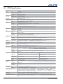
A.1 CC50 Specifications ...................................................................................................................A-2
A.1.1 CC50 Brightness and Performance Characteristics ............................................................A-3
A.2 CC67 Specifications ...................................................................................................................A-4
A.2.1 CC67 Brightness and Performance Characteristics ............................................................A-5
A.3 CC70 Specifications ...................................................................................................................A-6
A.3.1 CC70 Brightness and Performance Characteristics ............................................................A-7
A.4 CC72 Specifications ...................................................................................................................A-8
A.4.1 CC72 Brightness and Performance Characteristics ...........................................................A-9
Entero Projector and Cube Installation Manual
020-100839-01 Rev. 2 (04-2013)
iii
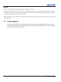
1 Introduction
This manual provides instructions for installing a display system using Christie Entero RPMSP–LED01,
RPMWU–LED01 or RPMHD–LED01 projectors, CC50, CC67, CC70, CC70HD and CC72 display cubes,
and PE50, PE67, PE70, PE70HD and PE72 pedestals.
The information within this manual is intended for audio visual technicians with experience installing display
systems. To avoid personal injury or damage to the projector, read all procedures before starting the installation
and observe all precautions. For information on installing the projector in a non–Christie enclosure, contact
your dealer. For information about using the projector, see RPMSP/RPMWU/RPMHD–LED01 User Manual
(P/N: 020-100367-xx).
1.1
Safety Warnings and Guidelines
Failure to comply with the following may result in death or serious injury:
• Tip Load! The maximum stacking limitation is 5 cubes high in a minimum 2 column display wall. The
display wall must be properly anchored anytime the wall is 2 rows or higher to prevent tipping and
provide stability. Use all the hardware provided to fasten the display cubes to the support structure.
See 2.8 Install Permanent External Support, on page 2-11.
• Disconnect the AC cord before disconnecting the light module from the Projector Head Module
(PHM).
Failure to comply with the following could result in minor or moderate injury:
• Do not look directly into the projection lens. The high brightness of this projector could cause permanent eye damage. For protection, keep all projector shielding intact during operation.
• Lift equipment must be used to lift the display cubes into position on rows 2 or higher. A crew of 2 or
more can lift a display cube into position on the first row.
• Always power down and disconnect/disengage all power sources to the projector before servicing or
cleaning.
• Mount the projector in a Christie display cube or to a sturdy, flat surface that fits the entire projector.
Use all 4 mounting points to secure the projector to the surface.
• Power should always be disconnected from
the light module before servicing, to avoid
the possibility of inadvertent exposure to visible LED radiation. Directly viewing the light
module optical output through certain optical
instruments (for example, eye loupes, magnifiers and microscopes) within a distance of
100 mm (3.94”) may pose an eye hazard.
Entero Projector and Cube Installation Manual
020-100839-01 Rev. 2 (04-2013)
1-1
NOTICES:
Failure to comply with the following may result in equipment damage:
• Maintain a minimum clearance of 25 mm (1.0”) around the projector for air circulation and a 75 mm (3”) clearance
for cable connections to the input panel. Insufficient clearance can cause the projector to overheat during operation
and/or place undue stress on source connections.
• This projector must be operated in an environment that meets the operating range specification, as listed in Appendix
A Specifications.
1.2
Contact Support
Trained service technicians are available to diagnose and correct system–related problems. If you encounter
any problems during the setup and installation of your system, contact the authorized dealer or Christie Partner
from whom the system was purchased.
1-2
Entero Projector and Cube Installation Manual
020-100839-01 Rev. 2 (04-2013)
2 Cube Installation and Setup
NOTICE: Only qualified installers should attempt installation of a Christie display wall.
NOTE: A clearance of 3 ft or more is recommended behind the display cube for serviceability and installation.
2.1
Christie Pedestals
Christie pedestals (models PE50, PE67, PE70, PE70HD, PE72) are recommended when you install Christie
display cubes (models CC50, CC67, CC70, CC70HD, CC72).
2.2
Stacking Limitations
Tip Load! The maximum stacking limitation is 5 cubes high in a minimum 2 column
display wall. The display wall must be properly anchored anytime the wall is 2 rows or higher to prevent
tipping and provide stability. Use all the hardware provided to fasten the display cubes to the support
structure. See 2.8 Install Permanent External Support, on page 2-11.
When stacking display cubes, they must be installed on a level surface. If the surface is not level the stacked
cubes could tip over and cause personal injury or damage to the cubes. Stacking limitations apply to all the
display cube models; the CC50, CC67, CC70, CC70HD, and CC80. Anytime the display wall is 2 rows or
higher the wall must be anchored to prevent tipping and provide stability. Christie recommends either using
tiebacks or lag bolts to secure the display wall. For details, see 2.8 Install Permanent External Support, on
page 2-11. Do not stack display cubes higher than the specified stacking limits. Stacking display cubes higher
than what is recommended increases the possibility of the display wall becoming unstable and unsafe. It also
increases the chance that the pedestals may buckle from the extra weight.death or serious injury.
STACKING HEIGHT
ANCHORING REQUIRED
(2 COLUMNS WIDE OR MORE)
1
No
2
Yes
3
Yes
4
Yes
5
Yes
Entero Projector and Cube Installation Manual
020-100839-01 Rev. 2 (04-2013)
2-1
2.3
Components and Hardware
All major components required to assemble a complete display cube are packaged and shipped separately to
the installation site. This includes the display cube enclosure, projector, display screen, and pedestal. Each
component comes with the hardware required for installation. Check the contents of your shipment against the
list below to make sure that you have all the necessary hardware. Hardware is listed by component and applies
to all models unless otherwise noted.
2.3.1 Cube Enclosures
• M6 x 75mm hex screws (Qty. 10)
• M6 x 18mm flat washers (Qty. 20)
• M6 lock washers (Qty. 10)
• M6 hex nuts (Qty. 10)
• M6 x 60mm hex screws (Qty. 2)
• M6 x 24mm flat washers (Qty. 4)
• Cable covers
• Long-screen bolts (Qty. 4)
• Short-screen bolts (Qty. 2)
• Panel plug
2.3.2 Screens
• M6 screws (Qty. 8)
• M8 set screws (Qty. 4)
NOTE: The long and short-screen bolts required to secure a screen to the cube are shipped with the cube.
2.3.3 Pedestals
• M6 x 75mm hex screws (Qty. 4)
• M6 flat washers (Qty. 8)
• M6 lock washers (Qty. 4)
• M6 hex nuts (Qty. 4)
• Cable covers (Qty. 4)
2-2
Entero Projector and Cube Installation Manual
020-100839-01 Rev. 2 (04-2013)
2.3.4 Entero Projectors
Each display wall requires a User Kit (P/N: 125-108100-xx). One User Kit is provided with each order, and 2
are provided with every 4 or more units ordered.
• Power Cord
• Entero User Kit (P/N:125-108100-xx).
Each kit includes:
• Entero Projector and Cube Installation Guide (this manual, P/N: 020-100839-xx)
• Entero RPMSP/RPMWU–LED01 User Manual (P/N: 020-100367-xx)
• IR remote control with 2 AA batteries
• Ball drivers: 8 mm, 5 mm, 4 mm (long), 2 mm
• Lint–free gloves (required for mirror and screen handling)
2.3.5 Recommended Installation Tools
• Level
• 10 mm hex wrench or socket driver
• 5 mm ball driver (provided with the user kit)
• 4 mm ball driver (provided with the user kit)
• Adjustable wrench
• Torque wrench
• #2 Phillips™ screwdriver
Entero Projector and Cube Installation Manual
020-100839-01 Rev. 2(04-2013)
2-3
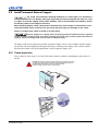
2.4
Unpack Cube Enclosures and Pedestals
NOTICES:
Failure to comply with the following may result in equipment damage:
• Do not cut the protective film off the mirror with a knife.
• Do not touch the optical mirror with your bare hands. Fingerprints left on the surface can impact image
quality.
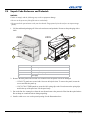
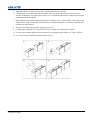
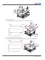
1. Lift the cardboard packaging off of the cube enclosures and pedestals. Do not cut the packaging with a
knife.
6
CC70
CC50
4
1
5
2
3
1, 3
Cable covers
2
CC50 back panel. Similar for CC72.
4
3 rear access panels for CC67, CC70, and CC70HD
5
Rear access panel spring release
6
Panel plugs
2. Remove the back panels and set aside in a location where the panels will not be damaged.
• CC50/CC72 panels are secured with 10 screws in keyhole slots. To remove the panel, loosen the
screws and slide the panel up.
• CC67/CC70/CC70HD panels are secured with 2 spring clips each. Press down on the spring clips
and tilt the top of the panel out. Lift the panel away.
3. Put on the lint–free cotton gloves from the user kit and remove the protective film from the optical mirror.
Do not bump or scratch the mirror during unpacking.
4. Install a cable cover over each exposed opening. See the illustration above.
2-4
Entero Projector and Cube Installation Manual
020-100839-01 Rev. 2 (04-2013)
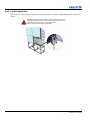
2.5
Unpack and Stabilize Screens
1. Wear the lint–free cotton gloves provided in the user kit, remove the screen from the packaging and stand
it vertically against a wall or flat surface. Select a low–traffic area away from the installation to protect the
screens from accidental scratching or tipping.
2. Let the screen stabilize to ambient site conditions for a minimum 24 hours.
3. Wearing lint-free cotton gloves, remove the protective film from the back of the screen.
2.6
Install the Pedestals
When you install Christie display cubes, Christie recommends that you use a Christie pedestal which is
designed to support the maximum stacking limit of the display cubes. Alternatively, custom designed pedestals
can be used; however, it is the responsibility of the designer/installer to make sure the custom structure meets
performance and safety requirements.
CUBE
PEDESTAL
CC50
PE50
CC67
PE67
CC70
PE70
CC70HD
PE70HD
CC72
PE72
Entero Projector and Cube Installation Manual
020-100839-01 Rev. 2(04-2013)
2-5
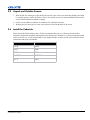
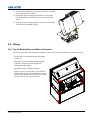
2
2
3
3
2
2
4
1
1
1
1
5
1
Use to fasten pedestals together, 4 on each side panel
2
Use to install display cubes, 2 at the back and 2 at the front
3
On PE67/PE70/PE72 pedestals only, use to install display cubes, 2 on support bracket
4
Front Panel (faces the room)
5
Adjustable feet (Qty. 4)
2.6.1 Construct a Multiple Pedestal Platform
Before starting, check that you have all the required hardware. See 2.3 Components and Hardware.
Failure to comply with the following could result in minor or moderate injury:
• Make sure that the appropriately rated lifting equipment and a minimum of 2 people are available for
installation.
• Mount the pedestals on a permanent, hard surface such as a concrete floor. Elevated surfaces, such as
wood platforms are not recommended.
NOTES: 1) Always start at the center and work outward, ensuring each pedestal is level. 2) Do not fully
tighten the hardware that attaches pedestals together until you have completed all of your adjustments and
installed all of the pedestals.
1. Slide 2 pedestals together and align the front and rear edges.
2. Apply downward pressure on the pedestal to make sure that the feet are flat to the floor.
3. Match the height of adjacent pedestals. Turn the bottom nut on each pedestal foot to raise or lower the
pedestal.
4. Use a level to verify that the pedestal is level on all sides and with the other pedestal.
2-6
Entero Projector and Cube Installation Manual
020-100839-01 Rev. 2 (04-2013)
5. Tighten the middle nut against the top nut to lock the pedestal foot in position.
6. Check that you can see threads inside the pedestal, at the top of the corner bracket where the foot is
installed. If threads are not visible, then you have over–extended the pedestal foot. Readjust the foot before
continuing with the installation.
7. Hand-tighten the 2 pedestals together using 4 M6 x 75mm hex screws, 8 flat washers, 4 lock washers, and
4 M6 hex nuts. Make sure that the vertical seam between adjacent pedestals is as narrow as possible and
uniform from top to bottom.
8. Slide the next pedestal into position and repeat steps 2 to 7.
9. Confirm that the platform is level and that all of the rear edges of the pedestals are aligned.
10. To secure the pedestals, tighten the loose hardware to a maximum torque setting of 11.1 Nm / 98 lbf-in.
11. Use a level to confirm that the platform structure is level.
Entero Projector and Cube Installation Manual
020-100839-01 Rev. 2(04-2013)
2-7
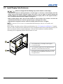
2.7
Install Display Cube Enclosures
Failure to comply with the following may result in death or serious injury:
• Tip Load! The maximum stacking limitation is 5 cubes high in a minimum 2 column display wall. The
display wall must be properly anchored anytime the wall is 2 rows or higher to prevent tipping and
provide stability. Use all the hardware provided to fasten the display cubes to the support structure.
See 2.8 Install Permanent External Support, on page 2-11.
• When stacking display cubes, they must be installed on a level surface. If the surface is not level the
stacked cubes could tip over and cause personal injury or damage to the cubes.
• Appropriate lift equipment must be used to list display cubes onto rows 2 or higher.
NOTE: A clearance of 3 ft. or more is recommended behind the display cubes for serviceability and
installation.
Before starting, check that you have all the required hardware. See 2.3 Components and Hardware. Complete
each row of cube enclosures before starting the next. Proper alignment reduces issues with image geometry and
makes sure that the wall has a seamless appearance. Once the wall is installed, it is difficult and timeconsuming to fix an alignment problem near the bottom of a wall.
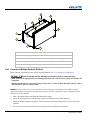
1
2
1
3
2
1
Use to fasten side–by–side display cubes together,
4 on each side panel.
2
Use to fasten the display cube to the pedestal or to the
cube below, 2 at the back and 2 at the front.
3
For CC67/CC70/CC72 display cubes only, use to fasten
the display cube to the pedestal or cube below it, 2 on
the support bracket.
3
2
1
2-8
1
Entero Projector and Cube Installation Manual
020-100839-01 Rev. 2 (04-2013)
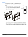
1. If space behind the display wall is limited, it is recommended the long-screen
bolts are inserted into the back of the cubes before the cubes are installed.
2. Install the first row of cube enclosures starting from the center and working
outwards.
a. From the back of the display structure, lift the cube enclosure over the
pedestal or cube row and lower it in the center of the pedestal or cube. A
crew of 2 or more can lift a display cube into position on the first row.
b. With the display cube enclosure resting on the lower level, adjust its
alignment so that the side and rear edges between the 2 components are
flush and the mounting holes are aligned.
short bolts
(used only on top row)
long screen bolts
Side View
c. Use 6 M6 x 75 mm screws (4 for CC50) with washers and hex nuts to secure the cube to the pedestal
or cube in the lower level. To allow for small adjustments, do not fully tighten the mounting hardware.
NOTE: For a single, stand–alone unit, tighten the hardware until components are fully secured, then
proceed to 2.9 Install Screens, on page 2-13.
d. Use 4 M6 x 75 mm screws with washers and hex nuts to attach the cube to the one adjacent to it. Hand
tighten the mounting hardware.
Entero Projector and Cube Installation Manual
020-100839-01 Rev. 2(04-2013)
2-9
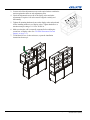
3. Loosen each of the adjustment screws on the optical mirror to minimize
tension against the mirror at each adjustment point.
4. Check the alignment between all of the display cubes and make
adjustments as required. All cubes must be aligned vertically and
horizontally.
5. Tighten all mounting hardware between the display cubes and pedestals
before installing another row of display cubes. Tighten hardware to a
maximum torque setting of 11.1 Nm / 98 lbf.-in.
6. Make sure that the wall is externally supported before adding the
second row of display cubes. See 2.8 Install Permanent External
Support, on page 2-11.
7. To add the next row of cube enclosures, repeat the installation
instructions from step 1.
2-10
Entero Projector and Cube Installation Manual
020-100839-01 Rev. 2 (04-2013)
2.8
Install Permanent External Support
Tip Load! The maximum stacking limitation is 5 cubes high in a minimum 2
column display wall. The display wall must be properly anchored anytime the wall is 2 rows
or higher to prevent tipping and provide stability. Use all the hardware provided to fasten
the display cubes to the support structure.
When stacking display cubes, they must be installed on a level surface. If the surface is not
level the stacked cubes could tip over and cause personal injury or damage to the cubes.
Failure to comply may result in death or serious injury.
External support for a display wall must be designed and implemented by a qualified
installer and must comply to local area safety standards. All display walls must have permanent external
supports. Failure to comply could result in minor or moderate injury.
All display walls must be supported externally anytime the display wall is 2 rows or higher. External support
prevents the wall from tipping and causing personal injury or damage to the display cubes. Christie requires
that either the tieback or the lag bolt application is used to support a display wall.
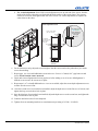
2.8.1 Tieback Application
Every column of cubes requires 1 tie back. Each tieback must be capable of withstanding a pull out force of
500 lbs.
DANGER! The amount of external support required is dependent on the size of
the display wall. Support structures must be designed and implemented by a
qualified installer and comply to local area safety standards.
Failure to comply results in death or serious injury.
Entero Projector and Cube Installation Manual
020-100839-01 Rev. 2(04-2013)
2-11
2.8.2 Lag Bolt Application
Each column
of cubes requires 4 lag bolts. Each lag bolt must be capable of withstanding a pull out force of
500 lbs.
DANGER! The amount of external support required is dependent on the size of
the display wall. Support structures must be designed and implemented by a
qualified installer and comply to local area safety standards.
Failure to comply results in death or serious injury.
2-12
Entero Projector and Cube Installation Manual
020-100839-01 Rev. 2 (04-2013)
2.9
Install Screens
NOTICE:
Failure to comply with the following may result in equipment damage:
• Read this entire section before installing the screens.
• Wear the lint-free gloves provided in the user kit when handling the screens to prevent leaving fingerprints on
the surface.
• Start with the center cube of the first row and work outwards.
• Check that you have all the required hardware. See 2.3 Components and Hardware.
1. Install the M6 depth adjustment screws and the M8 vertical alignment screws into the designated positions
on the screen. Make sure the screws are flush with the frame.
Insert M6 Depth Adjustment Screw
Insert Long–Screen Bolt
Insert M8 Vertical Alignment Screw
2. Working with a partner, lift the screen into position at the front of the display cube. Align the screen with
the cube face.
3. With 1 person supporting the screen from the front, secure the screen to the display cube using 4 long–
screen bolts. Hand-tighten the mounting hardware. Leave enough play to allow for alignment adjustments.
Install the long-screen bolts from the rear of the display cube and run them through the body of the cube.
4. For screens on the top row, use 2 long-screen bolts to secure the bottom of the screen and 2 short M6 x 60
mm screws to secure the top. Each M6 x 60 mm screw should have 2 M6 x 24 mm washers on it.
NOTE: Always complete installing screens on the first row before starting onto the next row.
5. Check and correct alignment and screen gap issues before adding another screen. NOTE: These
adjustments require 2 people. One person to make the adjustments on the inside of the frame and the other
person to check the adjustments on the outside of the frame.
a. For depth adjustment: Insert 4 M6 screws at each corner of the screen, from the inside of the frame
so that the screw surfaces are flush. Turn a screw clockwise to push the corresponding corner out from
the cube body.
Entero Projector and Cube Installation Manual
020-100839-01 Rev. 2(04-2013)
2-13
b. For vertical adjustment: Insert 2 M8 vertical alignment screws at each end of the screen, from the
inside of the frame so that they are flush with the inside surface of the screen frame. Turn a screw
clockwise to increase the height on that side of the screen. Use vertical adjustments to equalize the
seams between the cubes.
Screen adjustment screws
short– screen bolts
(for top row only)
From inside screen,
raise or lower
screen adjustment
screws to adjust
screen gap
0.5 mm
Hand–tighten
long–screen bolts
before setting
screen gap
Side View
6. For the bottom row only, adjust the screen height so that the screen touches the pedestals to prevent the
screen from shifting.
7. Repeat steps 1 to 4 to install additional screens in the row. Leave a 0.5 mm (0.019”) gap between each
screen. Work from the center outwards.
8. Check and correct alignment and screen gap issues before adding a row of screens. Misalignment is
difficult to correct once all screens are in place.
9. Repeat steps 1 to 7 to install additional rows. As rows are added, adjust the screen depth adjustment screws
to make sure the screen is flat.
10. Once the second row of screens has been installed, adjust the depth screws on the first row of screens, and
tighten the long–screen bolts to lock in place.
11. Once the third row of screens has been installed, adjust the depth screws on the second row, and tighten the
long–screen bolts to lock in place.
12. Continue until all rows have been completed.
13. Tighten all screen mounting hardware to a maximum torque setting of 4.5 Nm / 39.6 lbf.in.
2-14
Entero Projector and Cube Installation Manual
020-100839-01 Rev. 2 (04-2013)
3 Projector Installation and Setup
The projector is designed for installation in a Christie cube display or a custom display structure. Before
installing projectors, make sure that the screens have been installed and that screen depth and height
adjustments are complete.
For information about installing an Entero projector in a custom installation, see 3.5 Installing the Projector in
a Custom Structure.
Use a stable cart to transport the projector. See the drawings given for your specific projector model for the
mounting hole location, and other technical information and restrictions which may be useful during
installation.
3.1
What’s in the Box
• Projector Head Module (PHM), with attached Light Module (LM)
• Electronics Module (EM)
• Warranty Card
• Web Registration Form
• Line Cord (rated, North American)
NOTE: A User Kit is supplied with each projection system. Additional User Kits can be purchased separately
(P/N: 125-108100-xx).
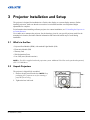
3.2
Unpack Projectors
The projector is shipped fully assembled.
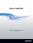
1. Remove the projector from the box. NOTE: Keep
packaging for 1 projector to use for returning a
projector for servicing.
2. Tighten the lens lock knob.
Lens Lock Knob
Entero Projector and Cube Installation Manual
020-100839-01 Rev. 2 (04-2013)
3-1
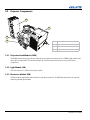
3.3
Projector Components
3
4
2
1
1
6–axis Adjuster
2
Projection Head Module (PHM)
3
Electronics Module (EM)
4
Light Module (LM)
3.3.1 Projection Head Module (PHM)
The PHM contains the projection lens, infrared sensor, digital micromirror device (DMD), light module, and
other optical components. The module includes the electrical connections that are used to drive these
components.
3.3.2 Light Module (LM)
The LM consists of 3 LEDs and associated optics.
3.3.3 Electronics Module (EM)
The EM module contains the main electronics and input connectors. If additional connections are required,
install an optional input module.
3-2
Entero Projector and Cube Installation Manual
020-100839-01 Rev. 2 (04-2013)
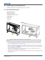
3.4
Install Projectors into Cube Enclosures
The PHM and adjuster plate are shipped installed on the 6–axis adjuster.
3.4.1 Tools and Hardware Required
•
•
•
•
•
•
•
•
M6 Cap screws (Qty. 8)
M5 Cap screws (Qty. 5)
M6 flat washers (Qty. 8)
M3 Phillips™ screwdriver (Qty. 2)
Cable ties (Qty. 5)
Cable anchor
M5 hex key
M4 hex key
CC50
Others
2
2
1
1
1
Location for 2 front M6 cap screws and washers, viewed from the front.
2
Slotted mounts on the 6–axis adjuster, viewed from the front.
1. For custom installation requiring direct throw, change the orientation of the projector before installing.
See 3.5 Installing the Projector in a Custom Structure.
2. Install the 2 front M6 cap screws and washers on the mounting plate in the cube. To allow for adjustment,
do not fully tighten the bolts. NOTE: The cube model determines the type and height of the mounting plate.
Projector installation is the same for all.
3. From the rear of the display cube, place the projector assembly on the mounting plate with the 6–axis
adjuster controls toward the back of the display cube.
4. Slide the projector assembly forward so that the slotted mounts in the base of the 6–axis adjuster align with
the M6 cap screws.
Entero Projector and Cube Installation Manual
020-100839-01 Rev. 2 (04-2013)
3-3
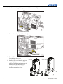
5. Install the remaining 2 M6 cap screws and M6 flat washers. Tighten all 4 screws.
only front screws shown
6. Remove the 4 shipping bolts from the adjuster.
Remove
Tape and
Loosen
Securing
Bolt
Before
Operation
Remove
Tape and
Loosen
Securing
Bolt
Before
Operation
shipping bolts
7. Turn the EM so the bracket extension
faces the back of the cube.
8. Install the EM to the left of the projector
using the 3 M6 cap screws and 3 flat
washers. The EM mounting location is
determined by the cube model. For
example in a CC70 cube, the EM
bracket is mounted to the rail.
3-4
CC50 / CC67
All other models
Entero Projector and Cube Installation Manual
020-100839-01 Rev. 2 (04-2013)
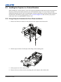
3.5
Installing the Projector in a Custom Structure
When installing in a custom structure, refer to the design and installation instructions for the custom structure.
Projector position and orientation should be part of the installation design. To review Christie–provided
information about the projector such as measurements, clearance requirements, and throw distance calculation,
download the CAD drawing for the projector. Visit www.christiedigital.com and search for your projector
model and CAD, for example RPMXX–LED01 CAD.
3.5.1 Change Projector Orientation for Direct Throw Installations
1. Remove the 2 M6 screws that secure the projector to the adjuster and set them aside.
2. Slide the projector back off of the pins on the flange of the mounting plate.
3. Set the projector on a level, stable surface.
4. Remove the 4 screws that secure the mounting plate to the adjuster, and set them aside.
Entero Projector and Cube Installation Manual
020-100839-01 Rev. 2 (04-2013)
3-5
5. Turn the adjuster 180°.
6. Align the holes on the mounting plate with the 4 holes on the adjuster, as shown.
180°
7. Secure with 4 mounting screws removed in step 4.
8. Unscrew the guide pins and re–install them in the mounting plate in the holes marked Pin H.
3-6
Entero Projector and Cube Installation Manual
020-100839-01 Rev. 2 (04-2013)
9. Loosely install 2 M6 cap screws (removed in step 1) onto the
back of the projector, as shown.
10. Position the projector with the guide holes over the guide
pins and the loosely install the screws over the slots in the
flange.
11. Settle the projector on the guide pins and secure to the flange
with M5 screws installed in step 9.
3.6
Wiring
3.6.1 Tips for Running External Cables to Projectors
All Christie cubes have cable channels in standard locations. Cable covers are included for external cube walls.
• System wide, keep cabling down to the lengths
you need.
• Run cables across the display wall through the
pedestals. Always keep cable lengths to a
minimum needed length.
• Run cables up the columns to displays.
• When you have run your cables, zip tie bundles
of like cables (zip ties not included). Zip tie cable
bundles to the anchors on the projector to prevent
putting strain on cables and connectors.
Entero Projector and Cube Installation Manual
020-100839-01 Rev. 2 (04-2013)
3-7
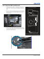
3.6.2 Connect the PHM to the EM and AC
1. Install the projector cables. To determine the location of
each cable, see the Interconnection Diagram affixed to the
LM.
2. Move the cables connecting the projector to the EM away
from the projector vents and the light path, and secure
with cable ties.
Interconnection Diagram
Electronics Module
EM Power
Link A
EM Network
Projection Head Module
Link A
EM Network
Light Module
9
3. Attach a cable anchor to the cube frame with an M6 cap
screw and a flat washer. Secure the projector power cable
to the anchor with a cable tie.
EM Power
Shown in lens-vertical configuration (top view)
Same connections for lens-horizontal configuration
3-8
Entero Projector and Cube Installation Manual
020-100839-01 Rev. 2 (04-2013)
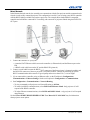
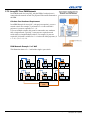
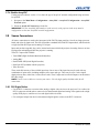
3.6.3 Connect Projectors for External Communication
By default, communications originating from one type of serial controller (RS232, RS422, or Ethernet) stay on
the corresponding network path. A Configuration > Communications > Network Routing > Separate setting
indicates this separation. For example, when using an RS422 controller, it will communicate only with the
projector to which it is connected, unless the setting is changed to RS232 and RS422 Joined or All Joined.
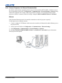
Ethernet
In the illustrated Ethernet network, the controller communicates with each projector separately.
To add a projector to an Ethernet network:
1. Connect a standard CAT5 Ethernet cable between the controller (or Ethernet hub) and the Ethernet port on
the projector EM.
2. Set the projector IP address in Configuration > Communications > Ethernet Settings.
3. Set Configuration > Communications > Network Routing to Separate.
See the Entero RPMWU/RPMSP/RPMHD–LED01 User Manual (P/N: 020-100367-xx) for information
about projector menu options.
Ethernet
et
ern
Eth ub
H
CAT5
CAT5
To other
Ethernet devices
Entero Projector and Cube Installation Manual
020-100839-01 Rev. 2 (04-2013)
CAT5
3-9
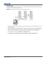
Mixed Network
In the illustrated mixed network, the controller can communicate with the first projector and the command can be
relayed to each serially connected projector. This configuration is useful if you are using a non–RS232 controller
with the RS232 linking available between these projectors. The example shows both an RS422–compatible
controller and an Ethernet–connected PC for working with a network of projectors linked using their RS232 IN/
OUT ports.
CAT5
et
ern
Eth ub
H
CAT5
1. Connect the controller to 1 projector:
• A standard CAT5 Ethernet cable between the controller (or Ethernet hub) and the Ethernet port on the
EM.
• A RS422 serial cable between the PC and the RS422 IN (pictured).
2. Connect a serial cable between the RS232 OUT connector of the first projector’s electronics module and
the RS232 IN connector of the next projector’s electronics module. Connect the remaining projectors.
RS232 communication cables must be of good quality and no more than 25 ft (7.6 m) in length.
3. If you connected the controller, using an Ethernet cable, set the IP address in Configuration >
Communications > Ethernet Settings. Set the serial options in Configuration > Communications.
4. Set Configuration > Communications > Network Routing:
• To relay commands to all projectors set Network Routing to All Join.
• To isolate just RS422 communications, select RS232 and Ethernet Joined. Only projector #3 will
respond to the RS422 controller.
• To isolate Ethernet communications, select RS232 and RS422 Joined—only projector #1 will respond
using Ethernet.
See the Entero RPMWU/RPMSP/RPMHD–LED01 User Manual (P/N: 020-100367-xx) for information
about projector menu options.
3-10
Entero Projector and Cube Installation Manual
020-100839-01 Rev. 2 (04-2013)
RS232 Network
In the illustrated RS232 network, the controller can communicate with the first projector and the command can
be relayed to each serially connected projector.
NOTICE: Using the wrong type of serial cable can damage the projector.
1. Connect the controller to one projector using a serial cable between the PC and the RS232 IN port on the
electronics module.
2. Connect a serial cable between the RS232 OUT connector of the first projector’s electronics module and
the RS232 IN connector of the next projector’s electronics module. Connect the remaining projectors.
RS232 communication cables must be of good quality and no more than 25 ft (7.6 m) in length.
3. Set the RS232 serial options in Configuration > Communications.
4. Set Configuration > Communications > Network Routing to RS232 and RS422 Joined.
Entero Projector and Cube Installation Manual
020-100839-01 Rev. 2 (04-2013)
3-11
Mixed Serial Network (RS232 and RS422)
RS422 serial communication is better over long distances than RS232 communication. Use the RS422 port only
if your device has the capability. Always read the equipment literature before connecting.
NOTICE: Connecting to the RS422 port with incompatible equipment, including the wrong type of serial cable,
can damage the projector.
In the illustrated RS–422 network, the controller can communicate with the first projector and the command can
be relayed to each serially connected projector.
1. Connect the controller to 1 projector using a RS422 serial cable between the PC and the RS422 IN port on
the electronics module.
2. Connect an RS232 serial cable between the RS232 OUT connector of the first projector’s electronics
module and the RS232 IN connector of the next projector’s electronics module. Connect the remaining
projectors using RS232 cables. RS232 communication cables must be good of quality and no more than 25
ft (7.6 m) in length.
3. Set the serial options in Configuration > Communications.
4. Set Configuration > Communications > Network Routing to RS232 and RS422 Joined.
3-12
Entero Projector and Cube Installation Manual
020-100839-01 Rev. 2 (04-2013)
3.7
Connect Projectors for ArrayLOC
Christie Entero projectors use Christie ArrayLOC technology to automatically and continuously synchronize
color and brightness settings across all projectors in an array.
3.7.1 Hardware Requirements
One or more external Ethernet switches are required to create a private ArrayLOC network. To make sure the
network operates effectively, do not connect the ArrayLOC network to other external or internal networks. To
isolate the ArrayLOC network, you can physically separate the ArrayLOC network switches. You can also isolate
specific ports on some switches. If you are able to isolate specific ports, you might not need to purchase
additional hardware.
There are 2 configuration methods for ArrayLOC wiring: PHM and EM. PHM is the recommended method. See
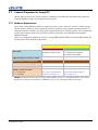
the chart below for the hardware requirements.
Selected ArrayLOC Network
PHM Network
EM Network
Description
Recommended option for new
installations to reduce switch
size
Typically used in installations with
pre–existing network hardware
between the EM and PHM.
Supported projector software versions
1.3.x or later
1.2.x or later
Additional Ethernet cables required
1
At least 1
Network switches required
At least 1
At least 1
Number of ports per switch
N = # of projectors
S = # of switches
(N + 2S) / S
(2N + 2S) / S
See Calculate Your Hardware
Requirement, on page 3-14.
See Calculate Hardware Requirements, on page 3-16.
Additional Hardware Requirements
NOTES: 1) Network switches do not need to contain a DHCP server (i.e., switches do not have to be routers).
2) Christie recommends, at minimum, a 100BASE–T type switch, 100 megabit Ethernet standard.
Entero Projector and Cube Installation Manual
020-100839-01 Rev. 2 (04-2013)
3-13
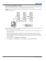
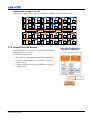
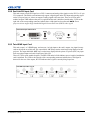
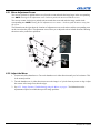
3.7.2 ArrayLOC Over PHM Network
In a PHM Network for ArrayLOC, only the PHM of each projector is
connected to the network switch. The projector EM remains connected to
the PHM.
Calculate Your Hardware Requirement
In an PHM Network for ArrayLOC, each projector requires 1 port on a
network switch. For example, if you install a 2 x 4 cube wall with 8
projectors, 8 ports are required (8 x 1 = 8).
If you use multiple switches, they must be connected to one another to
form a single network. Typically, 2 extra ports are required on each
switch when you install multiple switches. For example, 14 ports are
required if you install 3 switches for a 2 x 4 cube wall with 8 projectors (8
x 1 = 8) + (2 x 3 = 6) = 14.
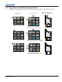
PHM Network Example: 2 x 3 Wall
This illustration shows a 2 x 3 wall with a single 6–port switch.
EM
EM
PHM
LM
EM
PHM
Adjuster
LM
EM
Adjuster
LM
LM
Adjuster
EM
PHM
PHM
Adjuster
EM
PHM
Adjuster
LM
PHM
LM
Adjuster
ArrayLOC Network
Switch
3-14
Entero Projector and Cube Installation Manual
020-100839-01 Rev. 2 (04-2013)
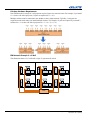
PHM Network Example: 4 x 6 wall
This illustration shows a 4 x 6 ArrayLOC configuration with three 10–port network switches.
EM
EM
PHM
PHM
EM
EM
PHM
PHM
EM
EM
Switch
PHM
PHM
EM
EM
PHM
PHM
EM
EM
Switch
PHM
PHM
EM
EM
PHM
PHM
Switch
EM
PHM
EM
PHM
EM
PHM
EM
PHM
EM
PHM
EM
PHM
EM
PHM
EM
PHM
EM
PHM
EM
PHM
EM
PHM
EM
PHM
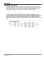
3.7.3 ArrayLOC Over EM Network
In an EM Network for ArrayLOC, the projector EM and PHM are
connected to a network switch.
To interconnect the projectors:
1. Disconnect the connection between the EM and the PHM.
2. Connect the EM Network port on the EM to an ArrayLOC
network switch.
3. Connect the EM Network port on the PHM to an ArrayLOC
network switch
Entero Projector and Cube Installation Manual
020-100839-01 Rev. 2 (04-2013)
3-15
Calculate Hardware Requirements
In an EM Network for ArrayLOC, each projector requires 2 ports on a network switch. For example, if you install
a 2 x 4 cube wall with 8 projectors, 16 ports are required (8 x 2 = 16).
Multiple switches must be connected to one another to form a single network. Typically, 2 extra ports are
required on each switch when you install multiple switches. For example, 22 ports are required if you install 3
switches for a 2 x 4 cube wall with 8 projectors (8 x 2 = 16) + (2 x 3 = 6).
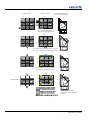
EM Network Example: 2 x 3 Wall
This illustration shows a 2x3 wall with a single 12–port network switch.
EM
EM
PHM
LM
EM
PHM
Adjuster
LM
Adjuster
EM
Adjuster
LM
LM
Adjuster
EM
PHM
PHM
EM
PHM
Adjuster
LM
PHM
LM
Adjuster
ArrayLOC Network
Switch
3-16
Entero Projector and Cube Installation Manual
020-100839-01 Rev. 2 (04-2013)
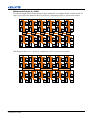
EM Network Example: 4 x 6 Wall
To reduce the length of the Ethernet cabling for larger installations, use multiple, smaller switches instead of a
single, large switch. This illustration shows an ArrayLOC configuration with 6 10–port network switches.
EM
PHM
EM
PHM
EM
PHM
EM
Switch
PHM
EM
PHM
EM
Switch
PHM
EM
PHM
EM
Switch
PHM
EM
PHM
EM
Switch
PHM
EM
PHM
EM
Switch
PHM
Switch
EM
PHM
EM
PHM
EM
PHM
EM
PHM
EM
PHM
EM
PHM
EM
PHM
EM
PHM
EM
PHM
EM
PHM
EM
PHM
EM
PHM
This illustration shows a 4 x 6 ArrayLOC configuration with 3 18–port network switches.
EM
EM
PHM
PHM
EM
EM
PHM
PHM
EM
EM
Switch
PHM
PHM
EM
EM
PHM
PHM
EM
EM
Switch
PHM
PHM
EM
EM
PHM
PHM
Switch
EM
PHM
EM
PHM
EM
PHM
EM
PHM
EM
PHM
EM
PHM
EM
PHM
EM
PHM
EM
PHM
EM
PHM
EM
PHM
EM
PHM
Entero Projector and Cube Installation Manual
020-100839-01 Rev. 2 (04-2013)
3-17
3.7.4 Enable ArrayLOC
If using projector software version 1.3.x or later, the type of ArrayLOC network configuration being used must
be specified.
1. Navigate to the Main Menu > Configuration > ArrayLOC > ArrayLOC Configuration > ArrayLOC
Network option.
2. Select an ArrayLOC Network type in the list.
IMPORTANT: For the ArrayLOC functionality to work correctly, each projector in the array must be
configured to use the sam ArrayLOC network configuration.
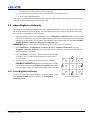
3.8
Source Connections
All source connections are made to the input panel of the EM. The input panel has 1 slot for an image processor
board, and 4 slots for input cards. The first slot includes a standard Dual Link DVI input module, which includes
a single dual link DVI input and an analog VGA input.
Input cards are hot swappable; they can be inserted and removed while the projector is running. Sources can also
be plugged in and unplugged while the projector is running.
There are 5 input cards available:
• Twin HDMI (High–Definition Multimedia Interface)
• Analog BNC
• Dual SD/HD–SDI (Serial Digital Interface)
• Dual Link DVI (standard with the projector)
• Video Decoder
These cards slide into any of the available input slots. One or more of the input slots may be used with any
combination of option cards, including multiples of the same card type. There may be up to 2 active inputs
displayed at any time, either from 1 card or from 2 cards. These 2 inputs can be routed to outputs or to the main or
PIP video image.
NOTE: Use the correct cable(s) to connect your source. Use only high–quality shielded cables for all
connections.
3.8.1 DVI Digital Video
• Use the DVI–I connector to connect either analog or digital video devices to the projector. Use a cable with
DVI–I connectors at both ends to connect devices that transmit digital and analog video signals such as high–
quality DVD players, satellite receivers and digital cable televisions.
• For true digital output from devices that transmit digital signals, connect to the DVI–I connector.
3-18
Entero Projector and Cube Installation Manual
020-100839-01 Rev. 2 (04-2013)
3.8.2 Dual Link DVI Input Card
This card accepts a single DVI signal over a DVI–I connector and analog video signals over the DVI–I or 15–pin
VGA connector. The module can simultaneously support a digital signal on the DVI input and an analog signal
on the VGA port; however, it does not support 2 analog signals at the same time. There are 4 LEDs on the
module faceplate. PWR indicates that power is applied and the card is initialized, and the other 3 LEDs on the
right–side of the corresponding connectors indicate that a valid signal has been detected. NOTE: Entero
projectors do not support High–bandwidth Digital Content Protection (HDCP) video signal.
3.8.3 Twin HDMI Input Card
This card accepts 1 or 2 HDMI inputs, and can route 1 or both inputs to the card’s outputs. Any input from any
card can be looped out of this card. The output label 1–OUT loops out the main image being displayed on the
projector. The output labelled 2–OUT loops out the image displayed in the picture–in–picture (PIP). Any input
from any optional input card can be looped out of this card.
There are 5 LEDs on the module faceplate. The PWR LED on the left side indicates power is applied, and that the
card is initialized. The LEDs to the right side of the corresponding connectors indicate that a valid signal is
detected. In the case of the outputs, the LED indicates that a signal is currently being looped out.
Entero Projector and Cube Installation Manual
020-100839-01 Rev. 2 (04-2013)
3-19
3.8.4 Analog BNC Input Card
This card accepts several types of Sync modes. In 5–wire Sync mode, all 5 BNC connectors are used. If H/C and
V connectors are swapped, this card will still operate normally. An analog graphic source, such as a VGA from a
PC, can be connected. The card can operate in 4–wire Sync mode, which accommodates 4–wire RGBC sources.
The composite Sync cable can be connected to either the H/C BNC or the V BNC. The card supports 3–wire
RGB or YPBPr Sync modes, sometimes called Sync–On–Green (SOG). In this mode, the H/C and V connectors
are not used. The Sync is connected to the Green/Y BNC connector. This card offers no loop–out capability.
There are 2 LEDs on the module faceplate. PWR indicates power has been applied, and the card is initialized.
Signal indicates a valid signal has been detected.
3.8.5 Dual SD/HD – SDI Input Card
This card accepts both standard–definition (SD) and high–definition (HD) serial–digital–interface (SDI) signals
from 1 of 2 SD or HD SDI sources. Both single–link HD and dual–link HD signals are accepted. The card has 2
SD/HD–SDI outputs, each of which is “loop through” for its respective input. There are 3 LEDs on the module
faceplate. PWR indicates power has been applied and the card is initialized, and the 2 Signal LEDs indicate a
valid signal has been detected on the respective input.
3-20
Entero Projector and Cube Installation Manual
020-100839-01 Rev. 2 (04-2013)
3.8.6 Video Decoder Input Card
This card accepts and decodes SD video. This includes CVBS (composite video), S–Video, and component
sources. This card supports as many as 6 video signals, 4 of them on BNC connectors and 2 on 4–pin mini–DIN
connectors. Each mini–DIN connector accepts one S–Video signal. The first BNC accepts composite video
(only), while the remaining 3 BNCs can be grouped to allow one of the following combinations:
• 3 CVBS sources on 4, 5 & 6
• 1 CVBS source, 1 S–Video source: Luma (Y) connected to 4 (Sy) and Chroma (C) connected to 6 (Sc)
• 1 YPbPr source: component signal on 4(Pr), 5(Y) & 6(Pb)
The video decoder input card has 8 LED indicators. The PWR LED indicates that the module is installed
properly, and has been successfully configured. The YPbPr LED indicates that a valid component signal has been
detected on inputs 4, 5, and 6. Component Input grouping must also be selected in the projector menu. The
remaining LEDs are each associated with 1 of the inputs and indicate that a valid signal has been detected on that
input.
Entero Projector and Cube Installation Manual
020-100839-01 Rev. 2 (04-2013)
3-21
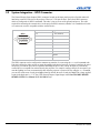
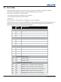
3.9
System Integration – GPIO Connector
The General Purpose Input Output (GPIO) connector located on the input panel provides a flexible method of
interfacing external I/O devices to the projector. There are 7 GIO pins on the 9–pin D–Sub GPIO connector,
which are configured via RS232 commands. The other 2 pins are reserved for ground, and power. The cable
required for connecting the external device to the projector GPIO connector, whether it is a standard serial cable
or a custom one, must be compatible with the external device.
GPIO
1
2
6
3
7
4
8
5
9
Pin Number
Signal
1,9
+ 12V (200mA)
2
GPIO 1
3
GPIO 2
4
GPIO 3
5
Ground
6
GPIO 4
7
GPIO 5
8
GPIO 6
9
GPIO 7
The GPIO connector can be configured to automate any number of events using the GIO serial command code.
Each pin is defined as either an input or output depending on the desired outcome. In general, configure the pin as
an input if you want the projector to respond to something the device does, and as an output if you want the
external device to respond to an action taken by the projector. For example, configure the pin as an output if you
want the lighting in a room to automatically dim when the projector is powered on. By using the GIO command,
you can also set the state of each pin as high or low. By default, the state of each pin is high. The voltage applied
to pins in the high state is + 3.3V. See (GIO) General Purpose Input/Output in the Entero RPMWU/RPMSP/
RPMHD–LED01 User Manual (P/N: 020-100367-xx).
3-22
Entero Projector and Cube Installation Manual
020-100839-01 Rev. 2 (04-2013)
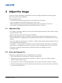
4 Adjust the Image
If necessary, make the adjustments outlined in this section for each display. Obtain the best results possible
before moving on to the next adjustment.
Image adjustments include:
•
•
•
•
4.1
6–axis adjustment: Adjusts image geometry to best match the screen perimeter.
Lens focus adjustment: Adjust for best image focus on the screen.
Mirror adjustment (only if required): Adjusts fine geometry around the perimeter of the screen.
Color primaries and brightness adjustment of individual projectors, if required.
Adjustment Tips
• In a multiple–cube display, adjust the center cube first, and then adjust the adjacent cubes to match, working
out and up from the center.
• Adjust 1 projector at a time until the entire wall is adjusted.
• Make a rough adjustment of the 6–axis adjuster, focus the image using the focus adjustment knob on the
lens, and lock the focus by tightening the focus adjustment knob. Then make a fine adjustment to the 6–axis
adjuster.
• Do not over–adjust the knobs on the 6–axis adjuster. A slight resistance during adjustment indicates the end
of the adjustment range for that knob.
• Use small 1/4 – 1/2 turns on the 6–axis adjuster to achieve the desired image. This will aid in returning the
adjuster back to an original position in the event you lose track of your adjustments and want to start over.
• The adjuster is shipped in nominal position. Nominals are marked; a flashlight may assist in
locating the marks.
4.2
Power the Projector On
Each projector is supplied with a power cord appropriate for your territory.
1. Plug 1 end of the power cord into the AC receptacle on the projector.
2. Plug the other end of the power cord into a grounded AC outlet. Use only an AC supply within the
specified voltage and power range.
3. Flip On the Power switch on the LM (Light Module). The projector takes about 2 minutes to initialize.
4. When the LED display shows 2 dashes and the status light is yellow, press the Power button, and then the
up arrow on the remote control.
Entero Projector and Cube Installation Manual
020-100839-01 Rev. 2 (04-2013)
4-1
4.3
Focus .64:1 Fixed Lens
The focus and geometry for Entero projectors are preset for installation in CC67 cubes. For all other installations,
follow the steps outlined below.
1. Press Test once on the remote to display the internal geometry test pattern. The test image should
approximately fill the screen. If not, make a course adjustment using the 6–axis adjuster (see 4.4 Adjust
Image Geometry Using the 6–axis Adjuster).
2. Loosen the corner focus–locking screw (A) and the center focus–locking screw (C).
A
B
C
3. Adjust the focus:
a. Adjust the focus at screen center (B).
b. Adjust corner focus and geometry by rotating the collar on the front of the lens. Use the illustration
below to gauge the preset position for your screen size.
120” 100” 80”
60” 50” 40”
c. Adjust the center focus (2) again for best overall screen focus.
4. Tighten the locking screws loosened in step 1.
4-2
Entero Projector and Cube Installation Manual
020-100839-01 Rev. 2 (04-2013)
4.4
Adjust Image Geometry Using the 6–axis Adjuster
Use the adjuster controls to adjust image geometry: position, keystone, zoom and tilt. Adjustment knobs are
color-coded. The 6–axis adjustment label on the product illustrates the function of each. Before making
adjustments, make sure the lock screws for each adjustment knob are loosened. Use the 5 mm hex key provided
to loosen the M6 lock screws and a 2 mm hex key (not provided) to loosen the collar lock screws. Tighten all lock
screws after image adjustments are complete.
Red Adjustment Knob: Use to adjust tilt.
Blue Adjustment Knob: Use to adjust the vertical position.
White Adjustment Knob: Use to adjust keystone.
Yellow Adjustment Knob: Use to adjust keystone.
Orange Adjustment Knob: Use to adjust the horizontal position.
Green Adjustment Knob: Use to adjust zoom.
unlocks
zoom control on
rear side of adjuster
The orientation of the projector in relation to the screen changes the effect of the knob adjustments. Vertical (lens
up) is the default installation. A label for the horizontal (lens forward) installation is included with the projector
for installations where the projector is configured for direct throw.
Entero Projector and Cube Installation Manual
020-100839-01 Rev. 2 (04-2013)
4-3
NOTES: 1) If it is necessary to make mirror adjustments do so only after you have completed this procedure.
2) Start with the displays in the center of the bottom row and work towards the end of the row.
1. Work from the back of the display cube. Make sure you can see all 4 sides of the image on the inside of the
screen.
2. Adjust the lens for best image focus on the screen. See 4.5 Fine–tune Image Geometry using the Mirror, on
page 4-5.
3. Press Test on the remote once to display the internal geometry test pattern. The image on the left in the
illustration below provides an example of what you will observe after installing the light engine and before
any adjustments are made.
4. Make the following adjustments for each display to achieve the image shown on the right in the illustration
below. The edge of the test image should be within 5 mm (0.2”) of the perimeter.
a. Adjust the vertical and horizontal position of the image until it is centered on the screen.
b. Zoom the image until it fits just inside the borders of the screen.
c. Adjust vertical and horizontal keystone, and tilt.
5. Once the image is geometrically aligned with the screen, as illustrated below in the image on the right,
zoom out until the edge of the test pattern is evenly aligned along the edges of the screen.
6. If necessary, readjust lens focus.
7. For each screen make sure image geometry matches between each display.
These adjustments usually require a second person in front of the display providing feedback and guidance with
display to display alignment. Start with the displays in the center cubes in the bottom row and work towards the
ends of the row. Then start with the next row in the same way.
a. Zoom out the image until it completely fills the screen.
b. If necessary, repeat step 4.
c. Repeat steps 1 to 6 for each display.
4-4
Entero Projector and Cube Installation Manual
020-100839-01 Rev. 2 (04-2013)
4.5
Fine–tune Image Geometry using the Mirror
NOTICE: Do not use tools to tighten the thumbscrews on the mirror to prevent the possibility of it cracking.
NOTE: Adjust the optical mirror only when image geometry cannot be corrected with the 6–axis adjuster.
This section outlines how to fine adjust the image geometry using the mirror adjustments. For example when the
edges of a single corner do not properly line up to the screen, or when a side of the image bows in or out slightly.
Guidance for fixing specific issues follows the general instructions for mirror adjustments. Mirror adjustments
should only be performed if absolutely necessary.
You can also use the mirror to correct slight misalignments between projected images where the edges align
properly with the screens, but adjoining images do not line up correctly.
Entero Projector and Cube Installation Manual
020-100839-01 Rev. 2 (04-2013)
4-5
4.5.1 Mirror Adjustment Screws
Turn screws clockwise to pull the mirror away from the screen and make the image larger in the corresponding
area. NOTE: Turning the D1 adjustment screw clockwise pushes the mirror towards the screen.
Turn screws counter–clockwise to push the mirror towards the screen and make the image smaller in the
corresponding area. NOTE: Turning the D1 adjustment screw counter– clockwise pulls the mirror away from
the screen.
The illustration on the right shows the locations of adjustment screws on the mirror and the corresponding zone
on the screen that they affect. The adjustment screws allow you to adjust the mirror in both directions. Meaning
the mirror can be pushed in or pulled out.
A
A1
C1
B
C2
B1
C
D1
B2
D
4.5.2 Adjust the Mirror
1. Loosen each of the thumbscrews. Turn each thumbscrew in either direction until you feel resistance. This
is the neutral position.
2. Turn the thumbscrews, in either direction to move the image 1 to 2 pixels from any corner or edge. Adjust
the corners of the image first, then the edges.
3. See 4.5.3 Image Geometry Troubleshooting using the Mirror, on page 4-7 for information on the
adjustments required to troubleshoot specific image problems.
4-6
Entero Projector and Cube Installation Manual
020-100839-01 Rev. 2 (04-2013)
4.5.3 Image Geometry Troubleshooting using the Mirror
The following examples illustrate what areas of the optical mirror to adjust to achieve the desired image.
Direction of Movement by
Mirror During Adjustment
Screws to Adjust
Image Problem
A1
C1
B1
C2
B2
D1
Turn thumbscrews clockwise in
zones C1–A–A1 to pull the mirror
A1
C1
D1
Turn thum bscrew s
in zones
C2
B1
B2
D1
Turn thumbscrews counter–clockwise
in zones C1–A–A1 to push the mirror
A1
C1
D1
Turn thum bscrew s
in zones
C2
B1
B2
D1
Turn thumbscrews clockwise
in zones C1–C2–A to pull the mirror
Entero Projector and Cube Installation Manual
020-100839-01 Rev. 2 (04-2013)
4-7
Image Problem
Screws to Adjust
Direction of Movement by
Mirror During Adjustment
A1
Image Problem
C1
Screws to Adjust
C2
A1
B1
B2
D1
Turn thumbscrews clockwise in
zones C1– C2 to pull the mirror
A1
C1
B1
C2
B2
D1
Turn thumbscrews clockwise in zones C and D,
and counter–clockwise in D1 to pull the mirror
A1
C1
B1
C2
B2
D1
Turn thumbscrews counter–clockwise
in zones A–A1–B to push the mirror.
A1
C1
B1
C2
B2
Linearity Problem
D1
Turn thumbscrews counter–clockwise
in zones C and B to push the mirror.
And/Or
Turn thumbscrews clockwise in zones
A–A1–B, C–D–D1 to pull the mirror.
And/Or
D-D1 counter–clockwise to pull the mirror.
4-8
NOTE: This adjustment is
required if the mirror is slightly
curved in.
Entero Projector and Cube Installation Manual
020-100839-01 Rev. 2 (04-2013)
4.5.4 Barrel and Pincushion Distortion
To correct barrel or pincushion distortion, adjust the A1 and B1, B2, C1, C2, and D1 mirror screws.
Barrel Distortion
4.6
Pincushion
Optimize Image Setup and Display
4.6.1 Initialization and Auto Setup
NOTE: To adjust image position, size/zoom, tilt, or keystone in a display wall system, see 4.4 Adjust Image
Geometry Using the 6–axis Adjuster, on page 4-3. Software adjustments to image geometry in a display wall
are rarely used.
1. Display an image from an external source. Use an image that has no black border and that contains at least
3 adjacent black and 3 adjacent white pixels for input level adjustments for analog sources.
2. If the image is not oriented correctly, select Configuration > Output Settings > Image Orientation and
change the orientation of the displayed image to suit the installation. For example, for Christie cube
installations, select Rear Projection Inverted.
3. Assign a unique projector ID number for each projector. Select Main Menu > Configuration >
Communications > Projector Address.
4. If the projectors are connected serially, you can check Broadcast Keys in the Communications menu for
the master projector. All other serially connected projectors should have this option cleared. Control the
master projector with a wired remote and commands are automatically forwarded to the other serially
linked projectors.
5. Select Auto Setup to allow the projector to setup the best possible settings for the chosen incoming signal:
image size based on resolution, horizontal and vertical phase and pixel tracking, and video input levels (for
analog sources).
6. Make sure that the Processing Mode (Image Settings menu) is correct for the selected source.
7. Change Resize Presets if you want the image displayed at a resolution other than Native. Native
resolution gives the best image quality.
8. For analog sources, adjust Pixel Phase and Pixel Tracking from the Size and Position menu to eliminate
noise from the displayed image.
Image settings for an input are stored in projector memory locations called channels. Starting Auto Setup will
create a new channel if any of the following conditions are met:
•
•
•
•
Change in the vertical frequency > .17Hz
Change in the horizontal frequency > 90 Hz
Change in either horizontal or vertical sync polarity
An interlaced signal is encountered
Entero Projector and Cube Installation Manual
020-100839-01 Rev. 2 (04-2013)
4-9
For information about managing channels, see the Entero RPMWU/RPMSP/RPMHD–LED01 User Manual
(P/N: 020-100367-xx).
4.6.2 Adjust Image Geometry Using the Projector Software
Only use projector software options if the images still requires adjusting after the hardware has been optimized
and Auto Setup has been run. See the Entero RPMWU–RPMSP–RPMHD–LED01 User Manual (P/N: 020100367-xx) for details about software based geometry changes: Size and Position, Resize Presets, Geometry
Correction.
4.6.3 Adjust Black Levels and Input Drives
For analog sources, optimize input levels.
1. Display the source image. The image must have at least 3 adjacent black and 3 adjacent white pixels. For
best results, display a 16–step grayscale pattern.
2. Select Main Menu > Image Settings > Input Levels.
3. Select Auto Input Levels.
4. When the values for black levels and input drives start to stabilize, clear Auto Input Levels.
5. Exit the projector menus.
NOTE: To adjust input drives and black levels manually, set black levels for all colors at full black. Set drive
levels at 60–70% white.
4.7
Adjust Color Using ArrayLOC
Use projector color adjustments to match the color primaries for all the
projectors in the array.
This procedure requires that the projectors are wired for ArrayLOC. See 3.7
Connect Projectors for ArrayLOC, on page 3-13.
1. Select Main Menu > Configuration > ArrayLOC > Array Color
Target.
2. Set Target Color Space to User 1.
3. Check that Copy Color Space From is set to Maximum.
4. Check that Select White Point is set to 6500 (D65).
5. Select 1 projector to work with and select Main Menu > Configuration > ArrayLOC > Synchronize to
This Projector.
6. Adjust colors for each projector in the array to calibrate the array as a system.
a.
b.
c.
d.
Select Main Menu > Configuration > ArrayLOC > Projector Color Adjustment.
Set Target Color Space to User 1
Use White Brightness Adjustment to match the brightness on all the projectors in the array.
Use the color settings (red part/green part/blue part) to adjust the color primaries to match across all
projectors.
• You may need to add some green to some of the reds.
• Greens are usually pretty consistent.
4-10
Entero Projector and Cube Installation Manual
020-100839-01 Rev. 2 (04-2013)
• You may have to add some red to some of the blues.
e. Use the white color settings to achieve a uniform white across all projectors.
f. Exit the color adjustment menus.
Once you have completed these adjustments, the ArrayLOC feature automatically monitors and maintains the
color and brightness uniformity across the display wall.
4.8
Adjust Brightness Uniformity
This brightness uniformity adjustment improves the brightness uniformity of the selected display cube; it does
not affect the uniformity across the display wall. This adjustment is rarely required, but when used it slightly
decreases the overall brightness of the projector.
1. Adjust the primary colors before attempting to work with Brightness Uniformity. Make sure that primary
colors, color temperature, and maximized light output are all well matched from 1 screen to another. These
matches are needed before you can achieve good brightness uniformity results. See the Entero RPMWU–
RPMSP–RPMHD–LED01 User Manual (P/N: 020-100367-xx).
IMPORTANT: Double–check that all WHITES and LIGHT OUTPUT are well–matched.
2. Select Main Menu > Configuration > Geometry & Color > Brightness Uniformity. Select the
Brightness Uniformity Enable check box. This will enable access to the uniformity controls and will
apply the settings to the image.
3. From Test Pattern, select the 13–Point test pattern for Full White
for display. The 13–Point test pattern provides 9 screen “zones”
with 13 targets.
4. Determine by eye or meter which areas need to be adjusted.
FOR BEST RESULTS Rather than examining the CENTER
of each zone when assessing Brightness Uniformity adjustments,
focus on extreme edges, as indicated in the illustration to the right.
4.8.1 Cancel Brightness Uniformity
If you do not want to use or apply brightness uniformity settings, clear
the Uniformity Enable check box at the top of the Brightness
Uniformity menu.
Entero Projector and Cube Installation Manual
020-100839-01 Rev. 2 (04-2013)
13–Point Test Pattern
4-11
5 Troubleshooting
NOTICE: To avoid personal injury or damage to the projector read, understand, and observe all warnings and
precautions before servicing the projector.
This section provides information and procedures for resolving common display issues. If you cannot resolve a
display issue, contact your dealer. Only Christie accredited service technicians are authorized to service this
product.
When diagnosing an issue:
• Make sure that the system is plugged in.
• Make sure that cables are connected and not damaged.
• Power off the system, wait 90 seconds to allow for cooling, and power the projector back on. Check for a
normal power up sequence.
• Check the projector LEDs for error codes and correct any issues if possible. See the user manual for your
projector.
• Check source connectivity. Switch sources if possible.
• Use RS232 serial communications to communicate with the projector during diagnosis.
5.1
System Warnings and Errors
A warning or error message appears when a projector malfunction occurs. These options are available for
viewing status and error information:
• LEDs on the input panel. See 5.3 LED Status Indicators.
• The Status window in the projector and web menus. The Status window updates automatically when the
error condition is corrected.
• On the projector display if system messages are enabled. To clear an error code on the projector display,
press Exit twice. If an error code recurs, reset the projector by turning it off and on. If an error code persists,
contact Christie Support.
• A warning message replaces the input signal message and disappears when the input signal status changes.
The projector remains operational, but the message indicates a serious problem that should be reported to the
Christie.
• A error message indicates a serious malfunction has occurred and it must be reported to the Christie. The
projector is not operational.
Entero Projector and Cube Installation Manual
020-100839-01 Rev. 2 (04-2013)
5-1
5.2
Error Codes
If the status display window shows one of the codes in the Error Codes table you may need a Christie
accredited service technician to repair the component identified by the error code.
Error codes are displayed in a 3–phase format:
• First 2 digits represent the component or error category
• Second 2 digits represent the specific problem
• Display off
This cycle repeats. The LED will be red while the error code is displayed.
Acknowledge and clear the error by pressing Exit twice when at the presentation level (no OSD on the screen).
If the error recurs then try resetting the projector by powering off and on again. Contact the dealer if the
problem persists or if you see a code not listed in the table.
CODE
DESCRIPTION
Light Engine (LE)
LE
01
Light engine link error
LE
02
Light engine initialization error
LE
03
Light engine run time error
Link (LI)
LI
01
Error on EM network
LI
02
Error on PHM network
LI
03
Error on ArrayLOC link
Projector Head Module Fan (FP)
FP
01
PHM FD Fan 1 stalled
FP
02
PHM FD Fan 2 stalled
FP
03
PHM LMC Fan 1 stalled
FP
04
PHM LMC Fan 1 stalled
Electronic Module Fan (FE)
FE
01
EM Fan 1 stalled
FE
02
EM Fan 2 stalled
Projector Head Module Sensors (SP)
5-2
SP
01
PHM FD sensor 1 overtemp or sensor not functioning
SP
02
PHM FD air inlet overtemp or sensor not functioning
SP
03
PHM FD air exhaust overtemp or sensor not functioning
SP
04
PHM FD DMD overtemp or sensor not functioning
SP
05
PHM QDPC board overtemp or sensor not functioning
Entero Projector and Cube Installation Manual
020-100839-01 Rev. 2 (04-2013)
SP
06
LM Air inlet overtemp or sensor not functioning
SP
07
LM C Air exhaust overtemp or sensor not functioning
SP
08
LM LED Driver overtemp or sensor not functioning
SP
09
LM Power supply overtemp or sensor not functioning
SP
10
LM ambient overtemp or sensor not functioning
SP
11
LM Red thermistor overtemp or sensor not functioning
SP
12
LM Green thermistor overtemp or sensor not functioning
SP
13
LM Blue thermistor overtemp or sensor not functioning
SP
14
LM IR thermistor overtemp or sensor not functioning
Electronics Module Sensors (SE)
SE
5.3
01
PHM FD sensor 1 overtemp or sensor not functioning
LED Status Indicators
LEDs on the projector indicate the projector status. This table lists the LED state and its associated meaning.
LED STATUS
2–CHARACTER DISPLAY
Rotating
Solid green
• Hardware initializing
• Waiting to establish connection with PHM
Solid yellow
DESCRIPTION
• Standby (connected to PHM)
BO (Booting) when power first applied
B1 (Boot phase 1) starting main script
B2 (Boot phase 2) starting projector
code
B3 (Boot phase 3) about to initialize
connections
When powering on (booting) the projector the LED
will go through phases, which are shown on the status
display.
• Powered ON
• Normal operations
• EM on
SH (Shutter Mode) active EM
System error – see corresponding error
code on status display
Solid Red
PR (Programming TI)
yellow
Keypad command sent – command received
Flashing green
• Key press error
• Wrong protocol sent
Flashing red
Entero Projector and Cube Installation Manual
020-100839-01 Rev. 2 (04-2013)
5-3
5.4
Projector Does Not Turn On
• Make sure the projector is plugged in.
• Make sure cables are connected and not damaged.
5.5
Light Module Suddenly Goes Off
1. Check shutter setting – if status display shows SH then the shutter may be active. Toggle through shutter
modes. In gray shutter mode it should be possible to display menus.
2. Verify RGB Brightness is set sufficiently higher than zero to ensure a visible image.The DMDs may be
overheated. Check for an alarm condition.
5.6
No Display When the Projector is On
1. Make sure the lens cover is removed from the lens.
2. Make sure the correct display button is selected in the channel setups.
3. Make sure AC power is connected.
4. Make sure an active source is connected properly. Check the cable connections and make sure the
alternative source is selected.
5. Make sure that the DVI cable from the PHM to the EM is connected.
6. Make sure the test patterns are accessible? If so, check source connections again.
5.7
The Display is Unstable
1. If the non–cinema display is jittery or blinking erratically, make sure the source is properly connected and
of adequate quality for detection. With a poor quality or improperly connected source, the projector
repeatedly tries to display an image, however briefly.
2. The horizontal or vertical scan frequency of the input signal may be out of range for the projector.
3. The sync signal may be inadequate. Correct the source problem.
5.8
The Display is Faint
1. The source may be double terminated. Make Sure the source is terminated only once.
2. The source (if non–video) may need sync tip clamping.
3. Make sure the RGB Brightness setting and the Brightness Uniformity settings are set to 100%.
4. If the Twist™ software was used, test by disabling the blend.
5. Brightness and/or contrast may be set very low.
5-4
Entero Projector and Cube Installation Manual
020-100839-01 Rev. 2 (04-2013)
5.9
The Upper Portion of the Display is Waving, Tearing or Jittering
1. Check that the RGB Brightness setting is not too low.
2. Check the signal level on the input device.
5.10 Portions of the Display are Cut Off or Warped to the Opposite Edge
If you have resized the image, adjust the resizing settings until the entire image is visible and centered.
5.11 Display Appears Compressed (Vertically Stretched)
1. Adjust the frequency of the pixel sampling clock for the input source.
2. Verify the size and position settings are correct for the input source.
3. Check the geometry correction for warp or keystone correction.
5.12 Data is Cropped from Edges
1. To display the missing material, reduce image size to fill the display area available in the projector, then
stretch vertically to fill the screen from top to bottom. Add the anamorphic lens to regain image width.
2. Check blend settings and masking.
5.13 Inconsistent Picture Quality
1. Verify the quality of the signal from the input source.
2. Verify the H and V frequencies of the input source are correct.
5.14 Static Display
1. Power the projector off and unplug the power cord from the power source.
2. Plug the projector power cord into a power source and power the projector on.
5.15 Inaccurate Display Colors
Adjust the color, tint, color space, and color temperature settings of the input source. Make sure you select the
correct PCF, TCGD, or color space file for the source.
5.16 Display is Not Rectangular
1. Verify the projector is level and the lens surface and screen are parallel to one another.
2. Adjust the vertical offset of the lens mount.
3. Verify the geometry correction settings.
Entero Projector and Cube Installation Manual
020-100839-01 Rev. 2 (04-2013)
5-5
5.17 Display is Noisy
1. Adjust the input source pixel tracking, phase, and filter.
2. Verify the video input is terminated (75 ohms). If the device is the last device in a linked series, verify the
video input is terminated at the last input source.
3. Verify the cables connecting the input device to the projector meet the minimum requirements.
4. Add signal amplification or conditioning if the distance between the input device and the projector exceeds
25 ft (7.6 m).
5-6
Entero Projector and Cube Installation Manual
020-100839-01 Rev. 2 (04-2013)
6 Maintenance
The following procedures are provided for use as needed. There is no required set maintenance schedule for
this product.
6.1
Ventilation
The operating environment in which you operate the display cubes should not exceed the temperatures defined
in Appendix A Specifications. Make sure there is adequate airflow around the display cubes.
6.2
Clean the Mirror
NOTICE: Typically, it is not necessary to clean the mirror; however, if required do not use ammoniated window
cleaner. This can damage the protective layer of the mirror. Aggressive cleaning techniques increase the risk of
mirror damage.
6.2.1 Items Required
•
•
•
•
•
•
•
Distilled or de–ionized water
Isopropyl alcohol (high purity with no coloration or additives)
Clean pure acetone (high purity with no additives)
Lint–free cloths (without color)
Cotton swabs, with non–synthetic stalks (wooden–stick)
Dry, clean compressed air
Cotton exam gloves and/or vinyl or latex exam gloves
6.2.2 Prerequisites
• Make sure the work area is free of fumes, fluids and dust.
• Put a support below the mirror to make sure it is equally supported during cleaning.
• Use cotton, vinyl or latex gloves when handling the mirror.
6.2.3 Instructions
NOTICE: Make sure there is no direct or diffused sunlight in the room. Do not wipe or rub the mirror surface.
Only light touch or “dab” the mirror.
Remove Water Droplet rings, marks, and other surface stains
Use isopropyl alcohol on the corner of a cotton wipe or a swab to “dab” the area. If stains cannot be
removed with the isopropyl alcohol use acetone as an alternative. Stains located in or under the protective
layer can not be removed.
Entero Projector and Cube Installation Manual
020-100839-01 Rev. 2 (04-2013)
6-1
Remove Finger Prints
1. Use a lint free cotton cloth with acetone and alcohol to dab the stain. For a finger print that is hard to
remove, use a cotton swab dipped in acetone.
2.
6.3
Use compressed air to dry the solvent.
Clean the Screen
Notice: Typically, it is not necessary to clean the screen; however, if required follow the guidelines listed here.
6.3.1 Items Required
• Mild soap or detergent diluted with luke warm water
• Lint-free cloths (without color)
• Chamois
• Cotton exam gloves and/or vinyl or latex exam gloves
6.3.2 Prerequisites
• Make sure the work area is free of fumes, fluids and dust.
• Never drop or slide screens on their edges or surfaces.
• Before laying screens onto flat work surfaces, lay foam slip sheets down to protect screen.
• Avoid laying screens on uneven or dirty work surfaces. Small chips or dirt particles can damage the screen
surface.
• Use cotton, vinyl or latex gloves when touching or handling the screen.
6.3.3 Instructions
1. Apply soap or detergent solution to lint–free cloth.
2. Wipe the screen surface to remove dirt or oils. Apply light pressure only.
3. Use another lint-free cloth and clean water to wipe the soap from the screen surface. Apply light pressure
only.
4. Use a dry lint–free cloth to blot the surface dry.
6-2
Entero Projector and Cube Installation Manual
020-100839-01 Rev. 2 (04-2013)
6.4
Clean the Projection Lens
NOTICE: Clean only if necessary. A small amount of dust on the lens has little effect on picture quality.
6.4.1 Items Required
• Camel–hair brush
• Lint free cloths (without color)
• Coated optics cleaning solution
6.4.2 Instructions
Remove Dust
1. Brush most of the dust from the lens with a camel-hair brush or blow dust away with a dust-free blower.
2. Fold a microfibre cloth smooth and gently wipe remaining dust particles from the lens. Wipe evenly with
the smooth portion of the cloth that has no folds or creases. Do not apply pressure with your fingers - use
the tension in the folded cloth itself to collect dust.
3. If significant dust is still bound to the surface, dampen a clean microfibre cloth with coated optics cleaning
solution (damp, not dripping). Wipe gently until clean.
Remove Fingerprints, Smudges, or Oil
NOTICE: Do not use a cleaning solvent that contains ammonia. Avoid lens contact with Xylene and Ether.
1. Brush away most of the dust with a camel-hair brush and/or blow away using a dust-free blower.
2. Roll a lens tissue around a swab and soak it in coated optics cleaning solution. Tissue should be damp, but
not dripping.
3. Gently wipe the surface using a figure-8 motion. Repeat this motion until the blemish is removed.
Entero Projector and Cube Installation Manual
020-100839-01 Rev. 2 (04-2013)
6-3
A Specifications
This appendix includes specifications and brief dimension drawings for the following display units:
•
•
•
•
•
CC50
CC67
CC70
CC70HD
CC72
Additional information and drawings are available for download from www.christiedigital.com.
Entero Projector and Cube Installation Manual
020-100839-01 Rev. 2 (04-2013)
A-1
A.1 CC50 Specifications
SXGA+
cube
t
CC50-2301
projection engine
t
RPMSP-LED01
screen options
t
SC50-LE02
imaging
t
1-c hip D LP, D a rk C hip
native resolution
t
S X G A + (1400 x 1050)
illumination
t
Light Emitting Diodes (Red, Green, Blue)
Pixel density
pitch
t
35 pixels per linear inch
Screen
gap
t
1mm nominal gap between adjacent images/screens
types
t
Wide angle cross prism
standard
t
Digital DVI-I with analog VGA
Product
make-up 1
Imaging
technology
Inputs
Illumination
Optical
t
High gain lenticular
scan rates
t
Horizontal: 15-120kHz
t
3 input module slots available
optional modules
t
VGA, Digital (DVI), Analog (RGB), dual SDI/HDSI, twin HDMI
compatibility
t Compatible with Christie TVC Series video wall controllers or other input sources from VGA to QXGA as well as standard HD for
t
LED (RGB)
t
>60,000 hrs
temperature
range
t
3200-9300K
technology
2
t
Vertical: 23.97-150Hz
t
Pixel clock: 165 MHz
gamut
t Beyond 100% EBU
adjustment
and control
t Screen to Screen: ArrayLOC automatic brightness and color management
lens types
t
0.69:1 low distortion, zero offset, with field curvature correction
brightness
uniformity
t
Brightness uniformity control provides up to 100% uniformity capability for critical applications
t
>100,000:1 (full field using shutter mode)
t
contrast ratio
t Individual: Comprehensive Color Adjustment (CCA™)
3
t 1400:1 (full field); up to 450:1 ANSI
Control/
networking
ports/controls
t
2 RS-232 ports and 1 RS-422 port t Field upgradable software via RS-232 network or Ethernet
IR remote control t GPIO port t On-board ChristieNET™ connectivity (RJ45)
Upgradability
software
t
Christie KoRE™ 10-bit librarian communication software for field upgrade of firmware
Optional
Accessories
inputs
t
See input option modules above
other
t
Wired remote control
Physical
characteristics
dimensions
t
Depth: 24"
weight (approx.)
t
Cube enclosure: 97lbs (44kg)
shipping weight
(approx.)
t
Cube enclosure: 130lbs (59kg)
stackability
t
Maximum of up to 5 units high. Tie backs or lagging required for units <2 units high.
service type
t
Rear access
Power rating
(projection
engine)
Reliability and
serviceability
t
t
Pedestal
See included line drawings for additional dimensions
t
Screen (XPS type): 46lbs (21kg)
t
t
Light engine: 60lbs (27kg)
Screen (XPS type): 70lbs (31.5kg)
Cube
Environment
t
Light engine: 68lbs (31kg)
Screens
operating
temperature 4
t
40-95°F (5-35°C)
t 63-88°F (17-31°C)
non-operating
temperature
t
-4-122°F (-20-50°C)
t
-4-95°F (-20-35°C)
humidity
t
20-80% non-condensing
t
40-60% non-condensing
altitude
t
0-3000m (0-10,000ft)
t
0-3000m (0-10,000ft)
voltage
t
100-240 VAC 50/60Hz
current
t
4.5A
consumption
t
Rating: 370W
dissipation
(maximum)
t
1263 BTU/hr
MTBF
t
>50,000 hrs MTBF for all major modules
MTTR
t
<15 minutes with modular design
t
t
Storage: 35-65% non-condensing
t
<5 minutes for lamp
t
t CAN/CSA C22.2 No
Directives: (EC) 2002/95/EC (RoHS) t 2002/96/EC (WEEE) t Regulation (EC) No. 1907/2006 (REACH)
t EN55022/CISPR22 Class A
t EN55024/CISPR24
UL 60950-1 t IEC 60950-1 t FCC, Part 15, Subpart B, Class A
t cULus (Canada & US) t CE (EU) t CCC (China) t GoST-R (Rus
Certifications marks (check with Christie for latest update):
KC (Korea) t PSE (Japan) t C-Tick (Australia & New Zealand)
Calibration
t
All projection units are factory calibrated for best color performance
Limited warranty
t
Two years parts and labor
Additional features and benefits
t
t Full-function remote keypad with easy-to-use men
Integrated 6-axis adjustment system for precise geometry alignment
t Picture-in-Picture capability t Control and status monitorin
Multiple set-up memories to manage multiple input sources
Regulatory (projection engine)
t
t
t
A-2
SC50-XP01
expansion
LED life rating
Color
t
t
Contact an authorized Christie representative for full details of our limited warranty
Entero Projector and Cube Installation Manual
020-100839-01 Rev. 2 (04-2013)
A.1.1 CC50 Brightness and Performance Characteristics
Engine option
Screen option
Screen type
Viewability
Horiz.
SXGA+
Horiz.
Verti.
Brightness
(cd/m 2 )
A RPMSP-LED01
t
SC50-LE02
t
Lenticular
t
160°
t
60°
t
±40°
t
±10°
t
913
RPMSP-LED01
t
SC50-XP01
t
Cross prism
t
180°
t
120°
t
±35°
t
±27°
t
470
B
1
Screen 1/2 gain
Verti.
1
Brightness specifications are at reduced color space settings.
Entero Projector and Cube Installation Manual
020-100839-01 Rev. 2(04-2013)
A-3
A.2 CC67 Specifications
SXGA+
cube
t
CC67-3001
projection engine
t
RPMSP-LED01
screen options
t
SC67-XP01
imaging
t
1-chip DLP, Dark Chip
native resolution
t
SXGA+ (1400 x 1050)
illumination
t
Light Emitting Diodes (Red, Green, Blue)
Pixel density
pitch
t
26.1 pixels per linear inch
Screen
gap
t
1mm nominal gap between adjacent images/screens
types
t
Wide angle cross prism
standard
t Digital DVI-I with analog VGA
scan rates
t
expansion
t 3 input module slots available
optional modules
t VGA, Digital (DVI), Analog (RGB), dual SDI/HDSI, twin HDMI
compatibility
t Compatible with Christie TVC Series video wall controllers or other input sources from VGA to QXGA as well as standard HD formats
Product
make-up 1
Imaging
technologies
Inputs
Illumination
Optical
t
Vertical: 23.97-150Hz
t
Pixel clock: 165 MHz
t
LED (RGB)
t
>60,000 hrs
temperature
range
t
3200-9300K
gamut
t
Beyond 100% EBU
adjustment
and control
t
Screen to Screen: ArrayLOC automatic brightness and color management
t Individual: Comprehensive Color Adjustment (CCA™)
lens types
t
0.69:1 low distortion, zero offset, with field curvature correction
brightness
uniformity
t
Brightness uniformity control provides up to 100% uniformity capability for critical applications
t
>100,000:1 (full field using shutter mode)
t
technology
2
LED life rating
Color
Horizontal: 15-120kHz
contrast ratio
3
t 1400:1 (full field); up to 450:1 ANSI
Control/
networking
ports/controls
t
2 RS-232 ports and 1 RS-422 port t Field upgradable software via RS-232 network or Ethernet
IR remote control t GPIO port t On-board ChristieNET™ connectivity (RJ45)
Upgradability
software
t
Christie KoRE™ 10-bit librarian communication software for field upgrade of firmware
Optional
Accessories
inputs
t
See input option modules above
other
t
Wired remote control
Physical
characteristics
dimensions
t
Depth: 30"
weight (approx.)
t
Cube enclosure: 141lbs (64kg)
t
Screen (XPS type): 90lbs (41kg)
shipping weight
(approx.)
t
Cube enclosure: 196lbs (89kg)
t
Screen (XPS type): 125lbs (45kg)
stackability
t
Maximum of up to 5 units high. Tie backs or lagging required for units <2 units high.
service type
t
Rear access
Reliability and
serviceability
t
Pedestal
See included line drawings for additional dimensions
Light engine: 60lbs (27kg)
t
Light engine: 68lbs (31kg)
Screens
operating
temperature 4
t
40-95°F (5-35°C)
t
63-88°F (17-31°C)
non-operating
temperature
t
-4-122°F (-20-50°C)
t
-4-95°F (20-35°C)
humidity
t
20-80% non-condensing
t
40-60% non-condensing
altitude
t
0-3000m (0-10,000ft)
t
0-3000m (0-10,000ft)
voltage
t
100-240 VAC 50/60Hz
current
t
4.5A
consumption
t
Rating: 370W
dissipation
(maximum)
t
1263 BTU/hr
MTBF
t
>50,000 hrs MTBF for all major modules
MTTR
t
<15 minutes with modular design
t
t
Storage: 35-65% non-condensing
t
<5 minutes for lamp
t
t CAN/CSA C22.2 No. 60950-1
Directives: (EC) 2002/95/EC (RoHS) t 2002/96/EC (WEEE) t Regulation (EC) No. 1907/2006 (REACH)
t EN55022/CISPR22 Class A
t EN55024/CISPR24
UL 60950-1 t IEC 60950-1 t FCC, Part 15, Subpart B, Class A
t
t
t
Certifications marks (check with Christie for latest update):
cULus (Canada & US)
CE (EU) CCC (China) t GoST-R (Russia)
KC (Korea) t PSE (Japan) t C-Tick (Australia & New Zealand)
Calibration
t
All projection units are factory calibrated for best color performance
Limited warranty
t
Two years parts and labor
Additional features and benefits
t
t Full-function remote keypad with easy-to-use menu system
Integrated 6-axis adjustment system for precise geometry alignment
t Picture-in-Picture capability t Control and status monitoring over IP
Multiple set-up memories to manage multiple input sources
Extensive scaling capability t Window/screen processing – external inputs can be displayed across an array of screens up to 3x3
without an external processor (a single input must be distributed to all cubes or it can be daisy-chained via use of the cube’s optional
Twin HDMI module) t 3 x Redundant cooling fans t Innovative water-filled, sealed heat pipe cooling system (maintenance free,
no motorized pumps, hazardous chemicals or concern of leakage)
Regulatory (projection engine)
t
t
t
t
t
Contact an authorized Christie representative for full details of our limited warranty
1 Cube, light engine and screen are sold separately.
2 LED lifetime is based on expected useful life to 50% brightness.
field and ANSI methods. Such values are critical for proper contrast performance assessment – especially for video walls.
electronic equipment, such as projection systems, are regularly operated at temperatures below 77°F (25ºC).
A-4
t
Cube
Environment
Power rating
(projection
engine)
t
3
The contrast ratio specified is the “natural” contrast ratio measured by both full
4 For best long-term performance and reliability, Christie recommends that all
Entero Projector and Cube Installation Manual
020-100839-01 Rev. 2 (04-2013)
A.2.1 CC67 Brightness and Performance Characteristics
Engine option
Screen option
Screen type
Viewability
Horiz.
SXGA+
1
RPMSP-LED01
t
SC67-XP01
t
Cross prism
t
180°
Screen 1/2 gain
Verti.
t
120°
Horiz.
t
±35°
Verti.
t
±27°
Brightness
(cd/m 2 )
t
1
260
Brightness specifications are at reduced color space settings.
Entero Projector and Cube Installation Manual
020-100839-01 Rev. 2(04-2013)
A-5
A.3 CC70 Specifications
WUXGA
cube
t CC70-3501
projection engine
t RPMHD-LED01
screen options
t SC70-XP01
imaging
t DIJQ%-P%BSL$IJQ
native resolution
t )%Y
illumination
t -JHIU&NJUUJOH%JPEFT3FE(SFFO#MVF
Pixel density
pitch
t QJYFMTQFSMJOFBSJODI
Screen
gap
t NNOPNJOBMHBQCFUXFFOBEKBDFOUJNBHFTTDSFFOT
types
t WJEFBOHMFDSPTTQSJTN
standard
t %JHJUBM%7**XJUIBOBMPH7("
scan rates
t )PSJ[POUBML)[ t 7FSUJDBM)[ t 1JYFMDMPDL.)[
expansion
t JOQVUNPEVMFTMPUTBWBJMBCMF
optional modules
t 7("%JHJUBM%7*
"OBMPH3(#
EVBM4%*)%4*UXJO)%.*
compatibility
t CPNQBtJCMFXJtICISJTtiF57$4FSJFTWJEFPXBMMDPOtSPMMFSTPSPthFSJOpVUTPVScFTfSPN7("UPQX("BTXFMMBTTtBOEBSE)%GPSNBtT
Product
make-up 1
Imaging
technologies
Inputs
Illumination
technology
LED life rating
Color
Optical
Control/
networking
t -&%3(#
2
t IST
temperature
range
t ,
gamut
t #FZPOE
adjustment
and control
t 4DSFFOUP4DSFFO"SSBZ-0$BVUPNBUJDCSJHIUOFTTBOEDPMPSNBOBHFNFOU
lens type
t MPXEJTUPSUJPO[FSPPffTFUXJUImFMEDVSWBUVSFDPSSFDUJPO
brightness
uniformity
t #SJHIUOFTTVOJGPSNJUZDPOUSPMQSPWJEFTVQUPVOJGPSNJUZDBQBCJMJUZGPSDSJUJDBMBQQMJDBUJPOT
contrast ratio
t TIVUUFSNPEF
t GVMMmFME
ports/controls
t 34QPSUTBOE34QPSU
t *OEJWJEVBM$PNQSFIFOTJWF$PMPS"EKVTUNFOU$$"
t 'JFMEVQHSBEBCMFTPGUXBSFWJB34OFUXPSLPS&UIFSOFU
t *3SFNPUFDPOUSPM t (1*0QPSU t 0OCPBSE$ISJTUJF/&5DPOOFDUJWJUZ3+
Upgradability
software
t $ISJTUJF ,P3&CJUMJCSBSJBODPNNVOJDBUJPOTPGUXBSFGPSmFMEVQHSBEFPGmSNXBSF
Optional
accessories
inputs
t 4FFJOQVUPQUJPONPEVMFTBCPWF
other
t WiSFESFNPUFDPOUSPM t 1FEFTUBM
Physical
characteristics
dimensions
t %FQUI t 4FFJODMVEFEMJOFESBXJOHTGPSBEEJUJPOBMEJNFOTJPOT
weight (approx.)
t $VCFFODMPTVSFMCTLH
shipping weight
(approx.)
t $VCFFODMPTVSFMCTLH
stackability
t .BYJNVNPGVQUPVOJUTIJHI5JFCBDLTPSMBHHJOHSFRVJSFEGPSVOJUTVOJUTIJHI
service type
t 3FBSBDDFTT
$VCF
ScSFFOT
operating
temperature 3
t ¡'¡$
t ¡'¡$
non-operating
temperature
t ¡'¡$
t ¡'¡$
humidity
t OPODPOEFOTJOH t 4UPSBHFOPODPOEFOTJOH
t OPODPOEFOTJOH
altitude
t NGU
t NGU
voltage
t 7"$)[
current
t "
consumption
t 3BUJOH8
dissipation
(maximum)
t #56IS
MTBF
t IST.5#'GPSBMMNBKPSNPEVMFT
MTTR
t NJOVUFTXJUINPEVMBSEFTJHO
Environment
Power rating
(projection
engine)
Reliability and
serviceability
Regulatory (projection engine)
t ScSFFO914UZQF
MCTLH
t -JHIUFOHJOFMCTLH
t ScSFFO914UZQF
MCTLH
t %JSFDUJWFT&$
&$3P)4
t -JHIUFOHJOFMCTLH
t NJOVUFTGPSMBNQ
t &$8&&&
t 3FHVMBUJPO&$
/P3&"$)
t 6- t *&$ t '$$1BSU4VCQBSU#$MBTT"
t $FSUJmDBUJPOTNBSLTDIFDLXJUI$ISJTUJFGPSMBUFTUVQEBUF
t &/$*413$MBTT"
t D6-VT$BOBEB64
t $"/$4"$/P
t &/$*413
t $&&6
t $$$$IJOB
t (P4533VTTJB
t ,$,PSFB
t 14&+BQBO
t $5JDL"VTUSBMJB/FX;FBMBOE
Calibration
t "MMQSPKFDUJPOVOJUTBSFGBDUPSZDBMJCSBUFEGPSCFTUDPMPSQFSGPSNBODF
Limited warranty
t 5XPZFBSTQBSUTBOEMBCPS
Additional features and benefits
t *OUFHSBUFEBYJTBEKVTUNFOUTZTUFNGPSQSFDJTFHFPNFUSZBMJHONFOU
t $POUBDUBOBVUIPSJ[FE$ISJTUJFSFQSFTFOUBUJWFGPSGVMMEFUBJMTPGPVSMJNJUFEXBSSBOUZ
t .VMUJQMFTFUVQNFNPSJFTUPNBOBHFNVMUJQMFJOQVUTPVSDFT
t 'VMMGVODUJPOSFNPUFLFZQBEXJUIFBTZUPVTFNFOVTZTUFN
t 1JDUVSFJO1JDUVSFDBQBCJMJUZ t $POUSPMBOETUBUVTNPOJUPSJOHPWFS*1
t &YUFOTJWFTDBMJOHDBQBCJMJUZ
t WJOEPXTDSFFOQSPDFTTJOHoFYUFSOBMJOQVUTDBOCFEJTQMBZFEBDSPTTBOBSSBZPGTDSFFOTVQUPY
XJUIPVUBOFYUFSOBMQSPDFTTPSBTJOHMFJOQVUNVTUCFEJTUSJCVUFEUPBMMDVCFTPSJUDBOCFEBJTZDIBJOFEWJBVTFPGUIFDVCF’TPQUJPOBM
t
5XJO)%.*NPEVMF
Y3FEVOEBOUDPPMJOHGBOT t *OOPWBUJWFXBUFSmMMFETFBMFEIFBUQJQFDPPMJOHTZTUFNNBJOUFOBODFGSFF
OPNPUPSJ[FEQVNQTIB[BSEPVTDIFNJDBMTPSDPODFSOPGMFBLBHF
1 $VCFMJHIUFOHJOFBOETDSFFOBSFTPMETFQBSBUFMZ
2 -&%MJGFUJNFJTCBTFEPOFYQFDUFEVTFGVMMJGFUPCSJHIUOFTT
FMFDUSPOJDFRVJQNFOUTVDIBTQSPKFDUJPOTZTUFNTBSFSFHVMBSMZPQFSBUFEBUUFNQFSBUVSFTCFMPX¡'¡$
A-6
3
'PSCFTUMPOHUFSNQFSGPSNBODFBOESFMJBCJMJUZ$ISJTUJFSFDPNNFOETUIBUBMM
Entero Projector and Cube Installation Manual
020-100839-01 Rev. 2 (04-2013)
A.3.1 CC70 Brightness and Performance Characteristics
Engine option
Screen option
Screen type
RPMHD-LED01
t SC70-XP01
t
Viewability
Horiz.
HD native
1
Cross prism
t
180°
Screen 1/2 gain
Verti.
t
120°
Horiz.
t
±35°
Verti.
t
±27°
Brightness
(cd/m 2 )
t
1
216
Brightness specifications are at reduced color space settings.
Entero Projector and Cube Installation Manual
020-100839-01 Rev. 2(04-2013)
A-7
A.4 CC72 Specifications
WUXGA
cube
t CC72-3301
projection engine
t RPMWU-LED01
screen options
t SC72-XP01
imaging
t DIJQ%-P%BSL$IJQ
native resolution
t 869("Yo)%DPNQBUJCMF
illumination
t -JHIU&NJUUJOH%JPEFT3FE(SFFO#MVF
Pixel density
pitch
t QJYFMTQFSMJOFBSJODI
Screen
gap
t NNOPNJOBMHBQCFUXFFOBEKBDFOUJNBHFTTDSFFOT
types
t WJEFBOHMFDSPTTQSJTN
standard
t %JHJUBM%7**XJUIBOBMPH7("
scan rates
t )PSJ[POUBML)[ t 7FSUJDBM)[ t 1JYFMDMPDL.)[
expansion
t JOQVUNPEVMFTMPUTBWBJMBCMF
optional modules
t 7("%JHJUBM%7*
"OBMPH3(#
EVBM4%*)%4*UXJO)%.*
compatibility
t CPNQBUJCMFXJUICISJTUiF57$4FSJFTWJEFPXBMMDPOUSPMMFSTPSPUIFSJOpVUTPVScFTfSPN7("UPQX("BTXFMMBTTUBOEBSE)%GPSNBUT
Product
make-up 1
Imaging
technologies
Inputs
Illumination
technology
t -&%3(#
2
LED life rating
Color
Optical
t IST
temperature
range
t ,
gamut
t #FZPOE
adjustment
and control
t 4DSFFOUP4DSFFO"SSBZ-0$BVUPNBUJDCSJHIUOFTTBOEDPMPSNBOBHFNFOU
lens type
t MPXEJTUPSUJPO[FSPPffTFUXJUImFMEDVSWBUVSFDPSSFDUJPO
brightness
uniformity
t #SJHIUOFTTVOJGPSNJUZDPOUSPMQSPWJEFTVQUPVOJGPSNJUZDBQBCJMJUZGPSDSJUJDBMBQQMJDBUJPOT
contrast ratio
t *OEJWJEVBM$PNQSFIFOTJWF$PMPS"EKVTUNFOU$$"
3
t GVMMmFMEVTJOHTIVUUFSNPEF
t GVMMmFME
VQUP"/4*
Control/
networking
ports/controls
Upgradability
software
t $ISJTUJF ,P3&CJUMJCSBSJBODPNNVOJDBUJPOTPGUXBSFGPSmFMEVQHSBEFPGmSNXBSF
Optional
accessories
inputs
t 4FFJOQVUPQUJPONPEVMFTBCPWF
other
t WiSFESFNPUFDPOUSPM t 1FEFTUBM
Physical
characteristics
dimensions
t %FQUI t 4FFJODMVEFEMJOFESBXJOHTGPSBEEJUJPOBMEJNFOTJPOT
weight (approx.)
t $VCFFODMPTVSFMCTLH
t ScSFFO914UZQF
MCTLH
shipping weight
(approx.)
t $VCFFODMPTVSFMCTLH
t ScSFFO914UZQF
MCTLH
stackability
t .BYJNVNPGVQUPVOJUTIJHI5JFCBDLTPSMBHHJOHSFRVJSFEGPSVOJUTVOJUTIJHI
service type
t 3FBSBDDFTT
$VCF
ScSFFOT
operating
temperature 4
t ¡'¡$
t ¡'¡$
non-operating
temperature
t ¡'¡$
t ¡'¡$
humidity
t OPODPOEFOTJOH t 4UPSBHFOPODPOEFOTJOH
t OPODPOEFOTJOH
altitude
t NGU
t NGU
voltage
t 7"$)[
current
t "
consumption
t 3BUJOH8
dissipation
(maximum)
t #56IS
MTBF
t IST.5#'GPSBMMNBKPSNPEVMFT
MTTR
t NJOVUFTXJUINPEVMBSEFTJHO
Reliability and
serviceability
t 'JFMEVQHSBEBCMFTPGUXBSFWJB34OFUXPSLPS&UIFSOFU
t *3SFNPUFDPOUSPM t (1*0QPSU t 0OCPBSE$ISJTUJF/&5DPOOFDUJWJUZ3+
Environment
Power rating
(projection
engine)
t 34QPSUTBOE34QPSU
Regulatory (projection engine)
t %JSFDUJWFT&$
&$3P)4
t -JHIUFOHJOFMCTLH
t -JHIUFOHJOFMCTLH
t NJOVUFTGPSMBNQ
t &$8&&&
t 3FHVMBUJPO&$
/P3&"$)
t 6- t *&$ t '$$1BSU4VCQBSU#$MBTT"
t $FSUJmDBUJPOTNBSLTDIFDLXJUI$ISJTUJFGPSMBUFTUVQEBUF
t &/$*413$MBTT"
t D6-VT$BOBEB64
t $"/$4"$/P
t &/$*413
t $&&6
t $$$$IJOB
t (P4533VTTJB
t ,$,PSFB
t 14&+BQBO
t $5JDL"VTUSBMJB/FX;FBMBOE
Calibration
t "MMQSPKFDUJPOVOJUTBSFGBDUPSZDBMJCSBUFEGPSCFTUDPMPSQFSGPSNBODF
Limited warranty
t 5XPZFBSTQBSUTBOEMBCPS
Additional features and benefits
t *OUFHSBUFEBYJTBEKVTUNFOUTZTUFNGPSQSFDJTFHFPNFUSZBMJHONFOU
t $POUBDUBOBVUIPSJ[FE$ISJTUJFSFQSFTFOUBUJWFGPSGVMMEFUBJMTPGPVSMJNJUFEXBSSBOUZ
t .VMUJQMFTFUVQNFNPSJFTUPNBOBHFNVMUJQMFJOQVUTPVSDFT
t 'VMMGVODUJPOSFNPUFLFZQBEXJUIFBTZUPVTFNFOVTZTUFN
t 1JDUVSFJO1JDUVSFDBQBCJMJUZ t $POUSPMBOETUBUVTNPOJUPSJOHPWFS*1
t &YUFOTJWFTDBMJOHDBQBCJMJUZ
t WJOEPXTDSFFOQSPDFTTJOHoFYUFSOBMJOQVUTDBOCFEJTQMBZFEBDSPTTBOBSSBZPGTDSFFOTVQUPY
XJUIPVUBOFYUFSOBMQSPDFTTPSBTJOHMFJOQVUNVTUCFEJTUSJCVUFEUPBMMDVCFTPSJUDBOCFEBJTZDIBJOFEWJBVTFPGUIFDVCF’TPQUJPOBM
5XJO)%.*NPEVMF
t Y3FEVOEBOUDPPMJOHGBOT t *OOPWBUJWFXBUFSmMMFETFBMFEIFBUQJQFDPPMJOHTZTUFNNBJOUFOBODFGSFF
OPNPUPSJ[FEQVNQTIB[BSEPVTDIFNJDBMTPSDPODFSOPGMFBLBHF
1 $VCFMJHIUFOHJOFBOETDSFFOBSFTPMETFQBSBUFMZ
2 -&%MJGFUJNFJTCBTFEPOFYQFDUFEVTFGVMMJGFUPCSJHIUOFTT
BOE"/4*NFUIPET4VDIWBMVFTBSFDSJUJDBMGPSpSPQFSDPOUSBTUQFSGPSNBODFBTTFTTNFOUoFTQFDJBMMZGPSWJEFPXBMMT
FRVJQNFOUTVDIBTQSPKFDUJPOTZTUFNTBSFSFHVMBSMZPQFSBUFEBUUFNQFSBUVSFTCFMPX¡'¡$
A-8
4
3 5IFDPOUSBTUSBUJPTQFDJmFEJTUIFiOBUVSBMwDPOUSBTUSBUJPNFBTVSFECZCPUIGVMMmFME
'PSCFTUMPOHUFSNQFSGPSNBODFBOESFMJBCJMJUZ,$ISJTUJFSFDPNNFOETUIBUBMMFMFDUSPOJD
Entero Projector and Cube Installation Manual
020-100839-01 Rev. 2 (04-2013)
A.4.1 CC72 Brightness and Performance Characteristics
Engine option
WUXGA
1
RPMWU-LED01
Screen option
t SC72-XP01
Screen type
t $rPTTQSJTN
Viewability
Screen 1/2 gain
Horiz.
Verti.
Horiz.
Verti.
t ¡
t ¡
t ¡
t ¡
Brightness
(cd/m 2 )
1
t #SJHIUOFTTTQFDJmDBUJPOTBrFBUrFEVDFEDPMPSTQBDFTFUUJOHT
Entero Projector and Cube Installation Manual
020-100839-01 Rev. 2(04-2013)
A-9
*000-103704-01*
ASSY TECH DOCS Entero Projector and Cube Install
*000-103704-01*
ASSY TECH DOCS Entero Projector and Cube Install
Corporate offices
Worldwide offices
USA – Cypress
ph: 714-236-8610
United Kingdom
ph: +44 118 977 8000
Eastern Europe
ph: +36 (0) 1 47 48 100
Singapore
ph: +65 6877-8737
Japan
ph: 81-3-3599-7481
Canada – Kitchener
ph: 519-744-8005
France
ph: +33 (0) 1 41 21 00 36
Middle East
ph: +971 (0) 4 299 7575
Beijing
ph: +86 10 6561 0240
South Korea
ph: +82 2 702 1601
Germany
ph: +49 2161 664540
Spain
ph: + 34 91 633 9990
Shanghai
ph: +86 21 6278 7708
For the most current technical documentation, please visit www.christiedigital.com