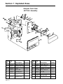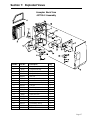
1
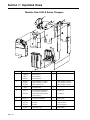
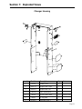
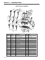
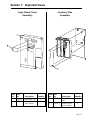
Coinco 9300-S SERIES ELECTRONIC CHANGER Operation and Service Manual Table of Contents Section 1: General Information Introduction ........................................................................................................................ 3 After Unpacking ................................................................................................................. 3 Model Explanations ............................................................................................................ 3 Features .............................................................................................................................. 3 Main Logic Board Assembly .............................................................................................. 4 Specifications...................................................................................................................... 4 Section 2: Installation Installing the Changer ......................................................................................................... 5 Vend Price and Option Switch Setting ................................................................................ 5 Section 3: Operation Coin Recognition ................................................................................................................ 7 Coin Separation ................................................................................................................... 7 Rejected Coin ...................................................................................................................... 7 Accepted Coin .................................................................................................................... 8 Credit & Accumulation ....................................................................................................... 9 Main Logic Board ............................................................................................................... 9 Coin Tube Sensing ............................................................................................................. 9 Change Payback ................................................................................................................10 Exact Change Condition ..................................................................................................... 10 Coin Payout .......................................................................................................................10 Dollar Credit Escrow Option ..............................................................................................10 Escrow ...............................................................................................................................10 Escrow Until Vend/Changer Vendor Interface ...................................................................11 Escrow Until Select/Changer Vendor Interface ................................................................. 12 Section 4: Maintenance Routine Maintenance ......................................................................................................... 13 Removing/Replacing Individual Module Assemblies ........................................................13 Cleaning .............................................................................................................................13 Disassembling Payout Base for cleaining ..........................................................................14 Clearing Coin Jams .............................................................................................................14 Section 5: Troubleshooting Introduction .......................................................................................................................15 Troubleshooting Guide ......................................................................................................15 9341-S Interconnect ........................................................................................................... 18 9342-S Interconnect .......................................................................................................... 19 Section 6: Accessories 9300-S.................................................................................................................................21 Section 7: Exploded Views Modular View .....................................................................................................................22 Changer Housing ...............................................................................................................23 Payout Assembly ............................................................................................................... 24 Logic Board Cover Assembly ............................................................................................25 Inventory Tube Assembly .................................................................................................25 Acceptor Front View .......................................................................................................... 26 Acceptor Back View ...........................................................................................................27 Page 2 Section 1: General Information INTRODUCTION acceptors (12-pin connector). This manual contains information on installing, operating and maintaining Coincos 9300-S series coin changers which included: The 9360-S directlly interfaces with both standard and non-standard bill validators, Cash Accountability TM, credit display and M.I.S.TM 9341-S ................. 117VAC 9342-SC .............. 24VAC 9360-S ................. 117VAC Familiarize yourself with this manual to obtain the best performance from your coin changer. The 9342-SC inferfaces with the standard 6-pin bill validator interface cable and 3-pin cash accountability meter. Refer to the model and serial number when calling for information. Both serial and model numbers can be found on the label on the side of the changer. · Accepts U.S. nickels, dimes, quarters and dollar coins. · Pays out nickels, dimes and quarters from selfloading, high capacity change tubes in least number of available coins. · Select high or low quarter tube level by simply flipping a switch. · Any vend price from $.05 to $12.75 in $.05 increments can be selected using a single switch module. · Dollar coins can be rejected or accepted by flipping a switch. · Heavy-duty D.C. payout solenoids provide fast, accurate payout. · Change capacity of $40.55 · Escrow until vend or escrow until select can be selected by simply flipping a switch. · Provides the fastest and most accurate coin acceptance of any electronic unit available today. · Directly interfaces with standard bill validator. No additional wiring is required. · Interfaces with non-standard bill validator with the addition of a 406890 adaptor harness. (9360-S and 9341-S) · Directly interfaces with cash accountability meter (through a 3-pin connector). Meter part number 406735. (9360-S and 9342-SC) · Directly interfaces with credit display, part number 406872. (9360-S only) · Pays out to the last coin in the changer tube to provide the maximum usage of a bill validator. Example: Serial number 1200008242 (week 12, year 2000). The first and second digits indicate the week of manufacture and the third and fourth digits indicate the year of manufacture. AFTER UNPACKING After unpacking the unit, inspect it for any possible shipping damage. If the unit is damaged, notify the shipping company immediately. Only the consignee (the person or company receiving the unit) can file a claim against the carrier for shipping damage. We recommend that you retain the original carton and packing materials to reuse if you need to transport or ship your changer in the future. If the coin changer is being stored or used as a spare, always keep it in its shipping carton when not in use. This will keep it clean and offer the best protection for the unit. MODEL EXPLANATIONS The 9341-S, 9342-SC, and 9360-S changers have a vend price setting up to $12.75 in five-cent increments and are equipped with electronic coin acceptance. They pay out nickels, dimes and quarters from self-loading coin tubes and accept nickels, dimes, quarters and dollar coins. The 9341-S directly interfaces with the standard 6pin bill validator interface cable and non-standard bill FEATURES Page 3 Section 1: General Information MAIN LOGIC BOARD ASSEMBLY SPECIFICATIONS The main logic board contains the microprocessor which controls all the functions of the coin changer based on information from other changer parts as well as the vending machine. Power Requirements 9341-S ....................................... 120 VAC, 60HZ 9360-S (95 to 130 VAC, 60HZ) 350 m Amp. Max Operating 1 Amp. Max During Payout Also contained on the main logic board is the power supply which receives the primary AC voltage from the vendor. From there the primary AC voltage goes two places: to be rectified to a DC primary voltage to operate the coin dispensing solenoids, and to the changer transformer where it is stepped down to a 12 VAC voltage. This 12 VAC is routed back to the control board where it is rectified and filtered for logic board operation. 9342-SC ................................... 24 VAC, 60(HZ) (20 to 32 VAC, 60HZ) 500 m Amp. Max Operating 3.5 Amp. Max During Payout Vend Price Range $.05 to $12.75 Operating Temperature 0 to 150 Degrees Fahrenheit -18 to 65 Degrees Celsius Storage Temperature -22 to 160 Degrees Fahrenheit -30 to 72 Degrees Celsius Physical Dimensions Height: 14.81 inches (base to top of coin return lever) Width: 5.28 inches (acceptor latch to acceptor latch) Depth: 2.86 inches (gate closed) Physical Weight in Shipping Carton 5.6 pounds Coin Tube Capacity Page 4 $.05 Tube $.10 Tube $.25 Tube Low Sensor Level 7 9 7 7 Full Sensor Level 78 113 77 22 Hand Load Level 86 125 95 22 LO $.25 LO $.25 Option Switch Option Switch Set to OFF Set to ON Position Position Section 2: Installation INSTALLING THE CHANGER See Figure 2 1. Remove the acceptor from the changer by releasing acceptor latches and pulling the top of the acceptor forward, away from changer. Unplug ribbon cable from changer. Free lower acceptor studs from changer housing. With the acceptor removed, set key holes in back of changer housing over mounting screw in the vendor. Tighten snugly. 3. Located in the upper portion of the changer is a single switch module with 12 rocker switches. When the top of the rocker switch is pushed in, it is in the ON position. The switches correspond according to the following table. SWITCH # 2. Set desired vend price and changer options (see Vend Price and Option Switch Settings). 3. Replace the acceptor by inserting bottom acceptor studs into changer housing guides. Plug the acceptor ribbon cable into the changer. Press top of acceptor into changer housing until top acceptor studs lock into changer's acceptor latches. 4. Connect changer to desired options. Plug changer into an 8-pin vendor socket. 5. Load coin tubes making sure all coins lie flat. 6. Test changer with a variety of coins to ensure proper operation and vend price setting. NOTE: SAVE THE COIN CHANGER CARTON. Always store coin changer in its shipping carton when not in use. This will keep the unit clean and protected. VEND PRICE AND OPTION SWITCH SETTINGS PRICE/OPTION 1 ............................................. $.05 2 ............................................. $.10 3 ............................................. $.20 4 ............................................. $.40 5 ............................................. $.80 6 ........................................... $1.60 7 ........................................... $3.20 8 ........................................... $6.40 9 ........................................... NOT USED 10 .......................................... $ coin acceptance 11 .......................................... LO $.25 12 .......................................... escrow until select 4. The vend price is set by adding the value of switches 1-8, which are in the ON position. Example: switches 1,3 and 4 in the ON position = $.65 vend price. 5. Set switches 1-8 to desired vend price. Make sure vend price set on changer corresponds to vend price indicated on front of vendor. 6. Set option switches 9-12 to desired setting. SWITCH # OPTIONS 9 NOT USED 10-$ACPT ON: Dollar coins will be accepted OFF: Dollar coins will be rejected 11-LO $.25 See Figure 2 ON: Quarters are directed to cashbox once change tube has approximately 22 quarters 1. Unplug the coin changer 2. Remove the acceptor. OFF: Quarters are directed to cashbox once change tube is full 12-ESC-SEL ON: Changer allows complete escrow until selection and delivery have been made. OFF: Changer allows escrow until vend price is accumulated. Page 5 Section 2: Installation Figure 2 Page 6 Section 3: Operation COIN RECOGNITION REJECTED COIN As a coin enters the changer through the acceptor funnel, its impact is absorbed by a white ceramic rail which debounces the coin and allows it to continue down the coin rail at a smooth and steady speed. As a coin rolls down the rail, it passes between two sets of LED sensors which measure the speed and size of the coin. The coin also passes between two sets of coils which measure the metallic content of the coin. These measurements are used to determine if the coin is valid and the value (denomination) of the coin. If a coin is rejected for any reason, both the UPPER (coin tube) and the LOWER (cash box) gate will remain closed. All rejected coins will drop into the vendor return cup via the coin changer coin return chute. See Figure 3 See Figure 4 COIN SEPARATION See Figure 3 After the coin's validity has been determined the coin rolls off the end of the coin rail and enters the separator section of the acceptor. The UPPER (coin tube) gate and the LOWER (cash box) gate are opened and closed by their respective solenoids. These solenoids are energized and de-energized by an electrical signal from the acceptor logic board based on the following criteria: the validity of the coin. the denomination of the coin. the status (full or empty) of the appropriate coin tube. The positions of these two gates cause the coin to be routed to one of three places: the appropriate changer coin tube, the vendor cash box, or if the coin is rejected, the vendor coin return cup. Figure 3 Figure 4 Page 7 Section 3: Operation ACCEPTED COIN See Figures 5 and 6 An accepted coin will be routed to either the vendor cash box or to one of the changer coin tubes. The (FULL) sensors in each coin tube determine which route the coin will take. If the coin tube corresponding to the validated coin is full (full sensor covered by coins in change tube), the cash box gate will open, allowing the coin to drop into the vendor Figure 5 Page 8 cash box via the changer cash box chute. If the appropriate coin tube is not full (full sensor not covered by coins), the coin tube gate will open directing the coin down a ramp. Along the wall of the ramp are windows for entry into the coin tube. As the coin reaches a window of the appropriate size, it falls into the coin tube. All dollar coins are always directed to the cash box via the cash box chute. Figure 6 Section 3: Operation CREDIT AND ACCUMULATION See Figure 7 There are two sensors, one in the separation section of the acceptor and one in the cash box path of the acceptor. As coins pass either one of these sensors, the changer sends credit information to the vendor electronic controller where the coin credit is accumulated. MAIN LOGIC BOARD The main logic board is responsible for all logic functions of the changer. It receives information from other changer modules as well as the vending machine, and based on this information, controls the operation of the changer. The main logic board also contains the changer power supply. It receives the incoming AC voltage from the vendor and does the following: First, it is rectified to a DC voltage for the payout solenoids. Second, it is routed to the transformers primary where it is reduced to 12 VAC. This 12 VAC is routed back to the logic board where it is rectified and filtered to the operating DC voltage. Figure 7 COIN TUBE SENSING See figure 8 The low tube sensors in each coin tube continually report the (blocked/not blocked) coin level to the microprocessor. This information is used to determine the availability of change for change payback, escrow and exact change condition. The full tube sensors in each coin tube continually report the (full/not full) status to the coin changers microprocessor. The information is then used to determine the placement of the next accepted coin. This information controls the action of the acceptor coin tube and cash box gates. EXAMPLE: If the quarter coin tube is full (full sensors blocked by coins) the acceptor coin tube gate will remain closed and the cash box gate will open each time a quarter is accepted, routing all quarters to the vendor cash box via the changer coin chute. After one or more quarters is paid out as change, leaving the full sensor exposed (quarter tube not full), the acceptor coin tube gate will open each time a quarter is accepted, routing quarters to the changer coin tube until it is full again. Figure 8 Page 9 Section 3: Operation NOTE: If the changer LO-$.25 option switch is set to the on position, accepted quarters will be routed to the cash box when the (middle $.25 tube sensor) is blocked by coins. Escrow Return: When a request for escrow is made, the changer will return the amount credited in the least number of coins. Under exact change conditions, nickles, dimes and quarters may be returned coin for coin. CHANGE PAYBACK The low tube sensors report which coins are available for payback so payout can be made in the fewest coins available. Manual Inventory of Coins: Operating the manual inventory switches manually empties the changer coin tubes. The inventory switches are located on the front of the inventory tube assembly. Only one inventory switch will operate at a time. EXACT CHANGE CONDITION DOLLAR CREDIT ESCROW The microprocessor is constantly looking at the change status. If correct change cannot be made, the changer rejects the last coin deposited, resulting in an over insertion. At this time, the correct change light flashes on and off in one second intervals for 10 seconds, during which time the escrow lever may be depressed for a full refund, the correct change my be inserted or the same coin which was rejected may be reinserted. (However, no change payout will be attenped under this condition.) If correct change cannot be made for a dollar bill, the correct change light will be lit continuously, inhibiting the bill validator. COIN PAYOUT The payout assembly pays out coins using three solenoid-operated slides. Coins are paid out for: change payout, escrow return and manual inventory of the coin tubes. When a solenoid energizes, the upward motion of its plunger compresses a spring and draws the soenoid lever, which in turn pushes a payout slide forward. This loads the coin for payout. When the solenoid de-energizes, the spring force returns the plunger to its de-energized state, which returns the solenoid lever and payout slide, dispensing a coin. Payout rate is two coins per second. Change Payout: When the amount of credit exceeds the vend price, a payout will be made in the least number of available coins. (See Exact Change Condition.) Page 10 Credit from the dollar bill validator or dollar coin is not inhibited from escrow. Four quarters will be returned to the customer if an escrow is called for. ESCROW Escrow Until Vend: Allows the customer to get a full refund any time before actual vend price is reached. Escrow Until Select: Allows the customer to receive a full refund any time prior to product delivery. NOTE: Then vendor circuit determines whether the escrow to select feature can be used. Section 3: Operation ESCROW UNTIL VEND CHANGER VENDOR INTERFACE See figure 9 and 10 As coins are inserted, the changers logic board compares the accumulated credit to the vend price. When adequate credit is reached, the changers logic board activiates the changers vend relay for 250 milliseconds. This energizes the vendors credit relay, cancels the changers credit and initiates the change making cycle if required. The energizing and latching of the credit relay removes power from Jones plug line six, which Changer Jones Plug inhibits the acceptance of coins and enables the selection switches for vending. The changers vend relays N/C contact connects the AC hot line to the vendors credit relays N/O contact. When a selection switch is activated, the vendors vend motor begins to run. The vend motor mechanically activiates a motor carrier switch which holds power to the vend motor until the motor returns to its home position and deactivates the vend relay of the vendor. This returns power to Jones plug line six enabling the acceptance of coins. 9300 SERIES CHANGER JONES PLUG PIN CONNECTION PIN # 1 2 3 4 5 6 7 8 FUNCTION VAC (HOT) VAC (NEUTRAL) VEND RELAY-NORMALLY OPEN NC (NO CONNECTION) EXACT CHANGE-NORMALLY OPEN (NUETRAL) ACCEPT COINS (HOT) VEND RELAY-NORMALLY CLOSED (HOT) NC (NO CONNECTION) Figure 9 Typical Changer to Vendor Interface Figure 10 Page 11 Section 3: Operation ESCROW UNTIL SELECT CHANGER VENDOR INTERFACE See figure 11 As coins are inserted, the changer microprocessor accumulates and holds the credit until a selection and delivery are made. When a selection is made, the changer senses the selection through Jones plug line three. If the accumulated credit is equal to or greater than the vend price, the chager will send a hot AC signal out on Jones plug line three, until the hot AC signal to Jones plug line six is borken. At this time, the changer will pay out any change owed and reset. Upon the return of the hot AC signal to Jones plug line six, the changer will stand by for the next transaction. If an escrow is detected while waiting for the hot AC signal to Jones plug line six to break, then the hot AC singal to Jones plug line six is monitored for two seconds. If the hot AC singal to Jones plug line six does not break in this two seconds, then an escrow of the accumulated credit is made. If the hot AC signal to Jones plug line six does break within two seconds, then the escrow is ignored and the changer pays out any change owed and resets. Upon the return of the hot AC signal to Jones plug line six, the changer will stand by for the next transaction. TYPICAL CHANGER TO VENDOR INTERFACE ESCROW UNTIL SELECT/DELIVERY Figure 11 Page 12 Section 4: Maintenance ROUTINE MAINTENANCE Routine maintenance will improve performance and extend the working life of the 9300 series changer and reduce the need for more involved repairs. Frequency of routine maintenance will depend on environment and number of transactions. The coin changer should be kept in its original shipping carton when not in use. This will keep the changer clean and provide the best protection for the unit. REMOVING/REPLACING INDIVIDUAL MODULE ASSEMBLIES Modular assembly replacement provides the basis of all 9300 series changer repair. Instructions for removing and replacing modules are provided below. These modules should be removed in the following sequence: Acceptor To remove the acceptor, raise the two acceptor latches and pull the top of acceptor forward and away from the changer housing. Unplug acceptor ribbon cable from main logic board. Raise acceptor and pull outward until the acceptor clears the housing slots. Coin Tube and Sensor Assembly Remove the logic board cover by inserting a straight tip screwdriver in the slot above the tube assembly. Twist the screwdriver to release the cover. Unplug tube sensor ribbon cable from logic board. Spread the lower part of the housing slightly and pullout on tube assembly. To separate the coin tube assembly from the tube sensor board assembly, place the assembly face down. While freeing the four locking tabs, pull up on tube sensor board. Be careful not to damage sensors on logic board. Main Logic Board Assembly Unplug payout solenoids, and main harness assembly from logic board. Lift logic board out of housing. Payout Assembly With payout solenoids disconnected from main logic board, remove the four screws - two from each sideat the bottom of the housing. Separate payout assembly from changer housing by releasing cash box chute locking tab on back of changer housing and pulling downward on payout assembly. CLEANING Your 9300 series changer is made of a high-quality industrial grade plastic which should only be cleaned with a warm water and mild detergent solution. CAUTION: Never submerge changer in water. Do not use petroleum solvents, steel wool, scouring pads, or a metal brush for cleaning. Do not spray any part of changer with any type of lubricant. Since all coins share a common coin ramp, heavy usage or a dirty environment can result in dirt build up. To clean the coin ramp, lift the acceptor gate upward and diagonally to the right. Hold gate firmly to prevent it from snapping back. Wipe the exposed coin ramp and inner surface with a damp cloth. For excessively dirty units, use a damp cloth with a mild detergent. NOTE: Do not submerge in water. For detailed cleaning of the acceptor, remove the front cover by pulling out and down of the front cover. Now remove the back cover by pushing in on two locking tabs on the side of the acceptor. To remove the coin sorting rail, snap the coin sense coils from the sorting rail and the cash box exit, being careful not to break coil wires. Free coil wires from the clip on the sorting rail. Now from the front of the acceptor, in area exposed by removing the front cover, locate the three locking tabs which secure the sorting rail. Using a small straight tip screwdriver, free the three locking tabs and remove sorting rail. See Figure 12. Page 13 Section 4: Maintenance DISASSEMBLING PAYOUT BASE FOR CLEANING Remove the four Phillips head screws from the bottom plate. Remove bottom plate and individual slides. Clean parts with mild detergent and hot water as desired. DO NOT SUBMERGE TRANSFORMER OR SOLENOIDS IN WATER. Replace slides making sure part numbers face up into changer. With the slides correctly seated on plunger tabs, reinstall the transformer and bottom plate, securing with bottom screws. The transformers black wires must be to the right (away from) the solenoids. Reinstall payout module into changer, securing with side screws. Figure 12 CLEARING COIN JAMS Should a coin jam occur in the cash box chute area, use the following steps to help dislodge coins: 1. Remove changer from vendor. 2. Keeping changer in an upright position, insert a narrow screwdriver into cash box chute or reject chute from bottom of changer to relieve jam. CAUTION: Excessive screwdriver pressure or twisting can cause permanent damage to the coin changer. Figure 13 Page 14 Section 5: Troubleshooting INTRODUCTION The Troubleshooting Guide on the following pages is intended to help locate problems within the coin changer. If a changer cannot be repaired by following the guide, return the changer to the nearest Coinco Service Center for repair. If it is necessary to return the changer to Coinco, please accompany the changer with a brief description of the malfunction to help expedite the repair and return of the changer. Logic troubleshooting minimizes time spent in removing and replacing modules that are not defective. Some failures are caused by minor problems such as loose or faulty connections. Please check the following before replacing any parts: Connectors are inserted correctly. Connector pins are not bent or broken. All wires are properly secured. Inventory tubes are filled to their correct levels. NOTE: The following Troubleshooting Guide is based on the fact that the tester or vendor, with which the defective changer is being tested, functions properly when used with a known good changer. This guide is not intended to cover all failures, but to cover the most common failures. 9300-S TROUBLESHOOTING GUIDE TROUBLE POSSIBLE CAUSE PROCEDURE REMEDY No coin acceptance and no payout when inventory switch is actuated. Changer appears to be dead No power Make sure the changer is plugged into the vending machine or tester has power Plug changer into vending machine or tester Hinge acceptor down, check red LED next to price otption switch, if LED is ON Replace main logic board If LED is OFF, check continually between Jones plug pin 1 and P3 pin 4 and Jones plug pin 2 and P3 pin 2. (See figure 14, 15, and 16.) If continuity does not exist between all 3 pairs Replace harness If continuity does exist between all three pairs check foil fuse on back of main logic board. (See figure 16.) Repair fuse or replace main logic board If fuse is good check transformer as follows: Check between P7 pins 1 and 2 for approximately 12-18 VAC (See fig.14, 15, and 16.) If no voltage less than 12 VAC Replace transformer If 12-18 VAC exists Replace main logic board Page 15 Section 5: Troubleshooting 9300-S TROUBLESHOOTING GUIDE TROUBLE POSSIBLE CAUSE PROCEDURE REMEDY No coin acceptance solenoids engergize when inventory switches are actuated Coin return lever Make sure changer is mounted correctly and coin return lever is in proper position Reposition changer and/or vendor coin return lever. Acceptor Make sure acceptor is plugged in properly Plug acceptor in properly No blocker (CREM) signal Hinge acceptor down and check to see that the red LED next to the price option switch is ON. Rejects coins or percentage of good coins Accepts money, but will not vend Accepts coins and vends but no payout Incorrect change payout Dirty acceptor Open circuit If not, check continuity between changers Jones plug pin 6 to P3 pin 4 If no continuity replace main harness If continuity is present Replace acceptor If still no acceptance Replace main logic board Clean the acceptor See cleaing proceedure Section 4 Maintenance If still rejects coin Replace acceptor If still rejects coins Replace main logic board Check continuity between Jones If open, replace main harness plug pin 3 & P3 pin 6 (see fig. 14-16) Check continuity between Jones plug pin 7 & P3 pin 5 If open, replace main harness Logic board or acceptor If continuity is present Replace logic board Payout solenoid does not engergize Actuate $.05, $.10, $.25 inventory switches one at a time. If any or all solenoids do not energize, check resistance of solenoids in question. Resistance should be .210 ohms + or - 10% if incorrect Replace solenoid or solenoids in question If resistance is correct Replace tube sensor board If still no inventory payout Replace main logic board Check solenoids for correct connection Connect solenoids correctly If solenoid connection is correct Replace main logic board After changin logic board there is still an incorrect payout Replace acceptor Main logic board or acceptor NOTE: If correct change is not available for a $ bill, the correct change light remains ON. See exact change condition, Section 3 Operation Page 16 Section 5: Troubleshooting 9302-GX TROUBLESHOOTING GUIDE TROUBLE POSSIBLE CAUSE PROCEDURE REMEDY Exact change light does not flash for an over insertion when correct change is not available Open circuit Check continuity between pin 5 of changer 8 pin Jones plug & P3 pin 1, if open Replace main logic board If harness is not open Replace logic board Vends at wrong price Logic board or acceptor Set vend price for $.50. Deposit $.25. Depress coin return. Deposit $.05. Depress coin return. Deposit $.10. Depress coin return. If amount returned doesnt equal amount deposited Check solenoids for proper connection. If problem still exists Replace logic board If the problem still exists Replace acceptor Check sensor boards for broken or loose components and check cable from sensor board for damage or improper connection Replace tube sensor board If coin still goes to cash box Replace acceptor If coin still goes to cash box Replace main logic board Coin tube gate in open position Remove acceptor back cover, check solenoid for free operation Repleace acceptor Defective tube sensor board Inspect tube sensor board for loose or broken components, frayed cable, etc. Replace tube sensor board If coin still goes to change tubes, Replace main logic board Coin always goes to cash box Coin always goes to coin tubes Does not accept dollar coin Tube sensor board or acceptor Dollar accept switch OFF Does not escrow properly in ESC/SEL mode Check for position of escrow option Fills $.25 tube when low $.25 tube level is selected Check low $.25 option switch in ON position Turn dollar switch ON If still doesnt accept dollar coin Replace acceptor If still doesnt accept dollar coin Replace main logic board Set escrow option. If set properly Replace main logic board If still no escrow Replace acceptor If quarter still goes to quarter tube Replace tube sensor board If quarter still goes to quarter tube Replace main logic board If quarter still goes to quarter tube Replace acceptor Page 17 Section 5: Troubleshooting 9341-S Wiring Diagram fig. 14 Page 18 Section 5: Troubleshooting 9342-S Wiring Diagram fig. 15 Page 19 Section 5: Troubleshooting 9360-S Wiring Diagram fig. 16 Page 20 Section 6: Accessories 9300-S Series Changers Page 21 Section 7: Exploded Views Modular View 9300-S Series Changers Item No. Part No. Qty. 1 408129 406777 406624-1 Harness 9341-S Harness 9360-S Harness 9342-SC 1 2 407336-5 407336-3 407336-4 Logic Board 9341-S, 9360-S Logic Board 9341-S, 9360-S Logic Board 9342-SC 1 3 922331 Changer Housing 1 4 407978-1 Payout and Housing Assembly 117 volt (9341-S, 9360-S) Payout and Housing Assembly 24 volt (9342-S) 1 407978-8 Page 22 Description Note GRAY acceptor connector BLACK acceptor connector GRAY acceptor connector includes #3 includes #3 5 406728-12 Inventory Tube Assembly 1 without decal 6 407755-4 407755-2 407755-1 Acceptor Acceptor Acceptor 1 GRAY connector GRAY connector BLACK connector 7 922332-1 Logic Board Cover 1 without decal Section 7: Exploded Views Changer Housing Item No. Part No. Description Qty. 1 922331 Housing (only) 1 2 902011-1 Acceptor Latch, Right 1 3 902010-1 Acceptor Latch, Left 1 4 909729 Label, Indentification 1 5 902224 24 VOLTS ONLY decal 2 6 909213 US Flag decal 1 7 921846-1 Patent label 9300-S 1 Note 9342-SC only Page 23 Section 7: Exploded Views 9300-S Payout Assembly Item No. 1 2 3 4 5 6 7 8 9 10 11 12 13 14 14a 14b 14c Page 24 Part No. Description 406607-1 406607-4 909113 909141 909630 406606-3 909105 909104 909103 922496 345P4R7 909135 909106 130-6R6 407351-1 407348-1 921105 921107 Solenoid assembly, 110VDC Solenoid assembly, 24V Pivot shaft Upper payout base Screw, 6-32 x 3/16 FH undcut blk Transformer assy, 110VAC, fused 10¢ Payout slide 5¢ Payout slide 25¢ Payout slide Lower payout base Screw, 4 x 7/16 PH PHL PLAS, blk Coin return liner Solenoid lever Screw, 6 x 3/8 PH Power supply board assembly (24V) Power supply board PCB bracket PCB support Qty. 3 1 1 6 1 1 1 1 1 8 1 3 2 1 1 1 3 Note 9360-S, 9341-S 9342-SC only 9360-S, 9341-S 9342-SC only 9342-SC 9342-SC 9342-SC 9342-SC Section 7: Exploded Views Logic Board Cover Assembly Item Part No. No. 1 2 922332-1 923058 Description Logic Board Cover Label Switch Options Inventory Tube Assembly Quantity 1 1 Item Part No. No. 1 909115-4 2 Description Inventory Tube Label 406728-12 Inventory Tube & Board Assembly Quantity 1 1 Page 25 Section 7: Exploded Views Acceptor Front View 407755-2 Assembly Item Part No. No. Description 1 406184-2 Gate & Coil Assy. 2 3 406567 906596-1 4 5 6 7 Page 26 Item Part No. No. Description 1 8 906618 Spring, Oper. Lev. 1 Gate Bd. Assy. LED Cover 1 1 9 10 400-8 406611 Nut, 8-32 Lock Mainplate & Coil Assy. 1 1 909095-2 906606-1 Front Cover Operating Lever 1 1 11 12 345-4R5 906616 Screw, 4x5/16 PH Coin Rail 2 1 906624 Screw, Gate Lever Pivot 1 13 923995 Acceptor Label 1 Retaining Ring 1 14 15 923984 921625 Gate Core Foam 1/4 LED Labels 1 4 751S21X Quantity Quantity Section 7: Exploded Views Acceptor Back View 407755-2 Assembly Item No. 1 2 3 4 5 6 7 8 9 10 11 12 13 14 15 16 17 18 19 Part No. Description 406611 406167 906619-2 906619-1 909096-1 407506-23 406612 909095-2 906596-1 906622-2 345S4R7 906600-1 909092 909853-1 406857-3 922609 406613-1 908845-1 921624 Mainplate and Coils Plunger and Yoke Assy. Spring, copper-plated Spring, nickel-plated Back cover Board assy. , CoinPro acceptor Rear chute and coil assy. Front cover Cover gate Pin, diverter pivot Screw, 4 x 7/16 PH Diverter door, upper Diverter door, lower Coin rail Solenoid assy. Mainplate foam Coin assembly, sensing Plug, spring retention PVC foam Qty. 1 2 1 1 1 1 1 1 1 2 2 1 1 1 2 1 2 1 1 Page 27 COIN ACCEPTORS, INC. 300 Hunter Avenue St. Louis, MO 63124-2013 (314) 725-0100 or (800) 325-COIN Coinco Publication No. 925197 Rev. 1 2/01 Printed in the U.S.A.