1
Luft/WasserWärmepumpe für
Schwimmbaderwärmung zur
Außenaufstellung
Installation and
Operating Instructions
English
Instructions d’installation
et d’utilisation
Français
Montage- und
Gebrauchsanweisung
Air-to-Water
Heat Pumps for
Swimming Pool
Heating (Outdoor
Installation)
Bestell-Nr. / Order no. / No de commande : 452159.66.11
Deutsch
LAS 10MT
LAS 15MT
LAS 22TT
Chauffage de
piscine par
pompe à chaleur
air/eau montée
à l’extérieur
FD 8704
Table of contents
1
Please Read Immediately .............................................................................................................E-2
1.1 Important Information:............................................................................................................................. E-2
1.2 Legal Regulations and Directives ........................................................................................................... E-2
1.3 Energy-Efficient Use of the Heat Pump .................................................................................................. E-2
2
Purpose of the Heat Pump ...........................................................................................................E-2
3
Scope of Delivery ..........................................................................................................................E-3
3.1 Basic Device ........................................................................................................................................... E-3
3.2 Switch Box .............................................................................................................................................. E-3
4
Transport........................................................................................................................................E-3
5
Installation .....................................................................................................................................E-4
5.1 General Information ................................................................................................................................ E-4
5.2 Condensed Water Pipe........................................................................................................................... E-4
6
Installation .....................................................................................................................................E-4
6.1 General Information ................................................................................................................................ E-4
6.2 Swimming Pool Connections .................................................................................................................. E-4
6.3 Electrical Connection .............................................................................................................................. E-5
7
Start-Up ..........................................................................................................................................E-5
7.1 General Information ................................................................................................................................ E-5
7.2 Start-Up .................................................................................................................................................. E-5
8
Description of Functions ..............................................................................................................E-6
8.1 Heat Pump Remote Control.................................................................................................................... E-6
8.2 Controller Board...................................................................................................................................... E-6
8.3 Heating Function..................................................................................................................................... E-6
9
Maintenance / Cleaning ................................................................................................................E-7
9.1
9.2
9.3
9.4
Maintenance ........................................................................................................................................... E-7
Cleaning the Pipe System in the Heat Exchanger.................................................................................. E-7
Cleaning the Air System ......................................................................................................................... E-7
Winter Shutdown / Lay-Up...................................................................................................................... E-7
10 Faults / Trouble-Shooting .............................................................................................................E-7
11 Decommissioning/Disposal .........................................................................................................E-7
12 Device Information ........................................................................................................................E-8
Anhang / Appendix / Annexes ............................................................................................................ A-I
www.dimplex.de
E-1
English
2.1 Application .............................................................................................................................................. E-2
2.2 Operating Principle ................................................................................................................................. E-2
1
1
Please Read
Immediately
1.1
Important Information:
ATTENTION!
When transporting the heat pump, ensure that it is not tilted more than
45° (in any direction).
ATTENTION!
English
The heat pump and transport pallet are only joined by the packing film.
1.3
Energy-Efficient Use of the
Heat Pump
To maintain heat pump efficiency, it is particularly important to
keep the temperature difference between the domestic hot water
and heat source to a minimum.
Suitable heating water temperature, a carefully chosen location
for the open-air pool, and the use of heat insulating pool covers
are just some of the measures used to reduce heat energy requirements.
It is important to ensure that the heat exchangers are not contaminated during operation because this increases the temperature difference, in turn reducing the COP.
ATTENTION!
Do not restrict or block the area around the air intake or outlet.
ATTENTION!
Ensure that there is a clockwise rotating field (for multiphase devices):
Operating the compressor in the wrong rotational direction could cause
damage to the compressor. Incorrect phase sequence causes wrong
rotational direction of the ventilator and, thus, a significantly reduced
performance.
ATTENTION!
Never use cleaning agents containing sand, soda, acid or chloride as
these can damage the surfaces.
ATTENTION!
Before opening the device, ensure that all circuits are isolated from the
power supply.
ATTENTION!
The warranty does not cover damage caused by inadequate lay-up
measures during the winter.
ATTENTION!
Work on the refrigerating circuit may only be performed by competent
personnel.
1.2
Legal Regulations and
Directives
The construction and design of the heat pump complies with all
relevant EU directives, DIN/VDE regulations (see CE declaration
of conformity).
When connecting the heat pump to the power supply, the relevant VDE, EN and IEC standards are to be fulfilled. Any further
connection requirements stipulated by local utility companies
must also be observed.
When connecting the heating system, all applicable regulations
must also be adhered to.
E-2
2
2.1
Purpose of the Heat
Pump
Application
The swimming pool heat pump is suitable for heating swimming
pool water or saline water.
The heat pump is equipped with an automatic evaporator defrosting (de-icing) system. The heat pump may also be operated
in frosty external air temperatures, providing operating limits and
conditions are observed.
2.2
Operating Principle
The surrounding air is drawn in by the ventilator and fed via a
finned heat exchanger, which extracts heat from the air. This energy difference is then transferred to the working medium (refrigerant) in the heat exchanger.
An electrically driven compressor “pumps” this extracted heat to
a higher temperature level by increasing its pressure. The heat is
then transferred to the water via a titanium heat exchanger.
During heating operation, electrical operating energy is used to
raise the temperature of the heat in the environment to a higher
level. Because energy extracted from the air is transferred to the
water that is to be heated, this device is referred to as an air-towater heat pump.
The swimming pool heat pump consists of the main components:
evaporator, ventilator and expansion valve, as well as the lownoise compressor, liquifier (titanium heat exchanger) and the
electrical control system.
During heating operation at low ambient temperatures, humidity
accumulates on the evaporator in the form of frost, impairing heat
transfer. The evaporator is automatically defrosted according to
need. Depending on atmospheric conditions, steam (water vapour) may be briefly visible in the immediate vicinity of the air
inlet or outlet when restarting.
4
3
Scope of Delivery
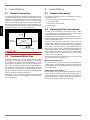
3.1
4
ATTENTION!
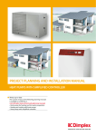
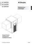
Basic Device
The heat pump is of compact design and is supplied complete
with the components listed below.
When transporting the heat pump, ensure that it is not tilted more than
45° (in any direction).
Use the wooden pallet for transporting the heat pump to its final
installation location. Either a lifting truck or 3/4" pipes fed through
the holes in the base plate or frame can be used for transporting
the heat pump.
R407C is used as refrigerant.
Transport
To avoid injuring your hands, ensure that the pipes cannot slip
when being used to lift the pump.
When inserting the pipes through the frame, ensure that the components are not damaged (especially the plastic condensate tray
and/or the drain stubs).
1)
Evaporator
2)
Switch box
3)
Ventilator
4)
Filter dryer
5)
Compressor
6)
Titanium heat exchanger
(Illustration: Front casing removed)
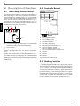
3.2
Switch Box
The switch box is located in the heat pump and can be accessed
by removing the covering panel assembly (the panel assembly
screw-holes are sealed by cover caps).
The switch box contains the supply connection terminals, as well
as the power contactors, the soft starter unit and the remote control connection terminals.
Heat pump control is via the remote control provided in the scope
of supply (see also Section 8).
www.dimplex.de
E-3
English
ATTENTION!
The heat pump and transport pallet are only joined by the packing film.
5
5
Installation
5.1
General Information
The device should always be installed on a permanently smooth,
even and horizontal surface. To counteract development of any
solid-borne sound, the entire frame (and its supporting surface)
should be in contact with the floor. If this is not possible, additional constructional measures to improve sound insulation may
need to be provided by the customer. It must be possible to carry
out maintenance work without hindrance. This can be ensured by
maintaining a clearance of 1.2 m around the device.
6
6.1
Installation
General Information
The following connections need to be established on the swimming pool heat pump:
Flow and return flow of the swimming pool system
Condensate outflow
Control line to remote control
Power supply
English
6.2
Swimming Pool Connections
The water pipe connections on the heat pump have 1" and/or
1 1/2" external threads. A pipe wrench must be used to firmly grip
the transitions when connecting the heat pump.
The water pipes are connected via a bypass on the filter circuit of
the swimming pool located downstream of the filter and upstream
of the water preparation system.
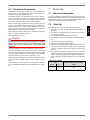
&OHDUHGDLURXWOHWGLUHFWLRQ
ATTENTION!
Do not restrict or block the area around the air intake or outlet.
5.2
Condensed Water Pipe
Condensed water that forms during operation must be drained
off frost-free. The heat pump must be mounted on a level plane
to guarantee proper drainage. The condensed water pipe must
have a minimum diameter of 50 mm and must be fed frost-free
into a sewer or a suitably dimensioned, deep gravel drainage pit.
The condensate pipe should be centrically placed under the
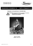
drain stubs of the condensate tray (see also the dimension drawing in the Appendix). Alternative means of condensate drainage
are to be agreed upon with the manufacturer.
Condensate should not be drained directly into clearing tanks
and cesspits because any rising, aggressive vapours could destroy the evaporator.
E-4
Before the water pipes are connected to the heat pump, the
swimming pool water system must be flushed to remove any impurities, sealant residue, etc. We strongly recommend installing
a filter system in the water circuit. Any accumulation of deposits
(leaves, grass or other organic contaminants) in the liquifier may
cause total breakdown of the heat pump. Suitable hydraulic installation, adjustment and dimensioning of the filter/circulating
pump ensures the minimum water flow rate through the heat
pump for trouble-free operation.
Once the water pipes have been installed, the system must be
filled, de-aerated and pressure-tested.
Minimum water flow rate
The swimming pool heat pump does not have an integrated circulation pump. The required water flow rate must be provided by
an external filter pump and signalled back to the heat pump via
the respective input.
Antifreeze (frost protection)
Manual drainage (see “Hydraulic Plumbing Diagram” in the Appendix) should be provided for heat pumps exposed to frost. To
ensure frost protection, a method of allowing the heat pump to
activate the filter pump must be installed (see the information in
Chapter 9.4 on winter shutdown/lay-up measures).
7.2
Electrical Connection
7
Start-Up
Depending on device type, the heat pump is connected to the
power supply via a standard 3-core cable (1-phase devices) or
standard 5-core cable (3-phase devices).
7.1
The cable(s) is(are) to be provided by the customer. The conductor cross section is selected in accordance with the power
consumption of the heat pump (see Appendix Device Information) and the applicable VDE (EN) and VNB regulations.
To ensure that start-up is performed correctly, it should only be
carried out by an after-sales service technician authorized by the
manufacturer. Only then can an extended warranty period of 3
years in total be granted (see Warranty Service).
Both an all-pole disconnecting device with a contact gap of at
least 3 mm (e.g. utility blocking contactor or power contactor), as
well as a 3-pole and/or 1-pole circuit breaker with common tripping for all external conductors (tripping current in compliance
with the Device Information) must be installed.
7.2
General Information
Start-Up
The following items need to be checked prior to start-up:
The heat pump must be fully connected, as described in
Chapter 6.
Ensure that the incoming supply has a clockwise rotating field
when connecting multiphase devices.
Any valves that might impair proper water flow in the water
circuit must be opened.
Phase sequence: L1, L2, L3.
The air intake and air outlet paths must be clear.
ATTENTION!
Ensure that there is a clockwise rotating field (for multiphase devices):
Operating the compressor in the wrong rotational direction could cause
damage to the compressor. Incorrect phase sequence causes wrong
rotational direction of the ventilator and, thus, a significantly reduced
performance.
The device supplies the control voltage to the remote control.
The connecting cable (control line) from the remote control to the
heat pump (not included in the scope of supply) must be suitable
for a 230 V supply voltage. The cable must be 6-core (at least)
and have a single-core cross section of at least 0.5 mm².
The heat pump power supply is in accordance with the technical
data of the device: 1/N/PE ~ 230 V, 50 Hz or 3/N/PE ~ 400 V,
50 Hz.
The heat pump is connected via the terminal strips in the switch
box. For detailed information see Circuit Diagrams in the Appendix.
www.dimplex.de
The ventilator must turn in the direction indicated by the arrow.
The remote control must be operational.
Ensure the condensate outflow functions.
After connecting the operating voltage and switching on the
swimming pool heat pump, there will be a pre-programmed
5-minute compressor pause time before the heat pump
starts up.
The bypass and regulator valves must be set so that the
minimum water flow is in accordance with the Device Information. The following maximum temperature spreads between water inlet and water outlet are set for the operating
point.
External air temperature
From
To
Max. temperature spread
between water inlet and water
outlet
18° C
20° C
6-7 K
15° C
18° C
5-6 K
E-5
English
6.3
8
8
Description of Functions
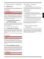
8.1
8.2
Controller Board
Heat Pump Remote Control
The heat pump can be switched on and off inside the building via
the remote control. In this context, switching off means the device is switched to a “standby” function, i.e. the frost protection
function remains active as long as voltage is supplied to the heat
pump. The filter pump runs when the air temperature is <5 °C.
The heat pump runs when the water temperature is <10 °C. The
temperature of the swimming pool water is adjusted via the adjustable transformer on the remote control.
English
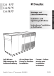
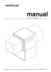
1)
On = Compressor running
2)
On = Ventilator running
3)
On = Defrost heater on
Off = Defrost heater off
1)
Switch on / standby
2)
The green LED lights up independent of the switch position
(indicating the heat pump is operationally ready)
4)
On = Filter pump request
5)
Off = Output of heat generator 2 - off
3)
Has no function
6)
4)
Setpoint regulator for water temperature
On = Frost protection request
Off = Frost protection request - off
Position max. (right-hand stop), hot water set temperature:
40 °C.
7)
On = Low-pressure switch in working order
8)
Not used
Position min. (left-hand stop), hot water set temperature: 10 °C.
9)
Not used
The setting knob has two setting rings for mechanically limiting
the setting range. (Note: before adjusting the setting rings, the
setting knob must be set to the approximate middle of the desired
setting range.)
10) Not used
11) Flashes when the controller board is in use
12) Flashes in the case of a fault
8.3
Heating Function
Start the heat pump by moving the switch (1) to the On position
(I). The desired return temperature is set via the rotary knob (4).
This is requested via the potentiometer and lies within a range of
10 °C min. and 40 °C max. Once the set temperature is reached,
the heat pump switches off. It switches on again when the return
temperature sinks to 1 Kelvin below the set value. It is not possible to re-start the heat pump until after a minimum pause time of
20 minutes (after defrosting of the evaporator). The heat pump
switches off at a maximum flow temperature of 45 °C, or when
the air temperature is too low (lower operating limit -10 °C).
E-6
11
Maintenance / Cleaning
9.1
Maintenance
To protect the paintwork, avoid leaning or putting objects on the
device. External heat pump parts can be wiped with a damp cloth
and domestic cleaner.
ATTENTION!
Never use cleaning agents containing sand, soda, acid or chloride as
these can damage the surfaces.
To prevent faults due to sediments in the titanium heat
exchanger of the heat pump, ensure that the heat exchanger
cannot be contaminated (water treatment and filter system necessary). In the event that operating malfunctions due to contamination still occur, the system should be cleaned as described below. (Warning: the fins on the finned tube heat exchanger are
sharp-edged -> danger of being cut!)
10 Faults / TroubleShooting
This heat pump is a quality product and is designed for troublefree and maintenance-free operation. However, if a fault does occur, use the following information to check whether you can eliminate the fault yourself.
The heat pump will not run!
Please check whether:
There is supply voltage (tripped fuse, power failure).
The operating switch on the remote control is switched on,
and whether the correct setpoint temperature has been set.
The set temperature level cannot be reached!
Please check whether:
The permissible operating conditions for the heat pump
have been adhered to (air temperatures too high or too low).
The air inlet or outlet area is blocked, restricted or very dirty.
There are closed valves or stop-cocks in the water pipes.
9.2
Cleaning the Pipe System in
the Heat Exchanger
Contamination in the pipes and heat exchanger can reduce the
performance of the heat pump’s titanium heat exchanger. If this
is the case, the pipe system and heat exchanger must be
cleaned by a technician.
Use only pressurised drinking water for cleaning.
9.3
Cleaning the Air System
The finned heat exchanger, ventilator and condensate outflow
should be cleaned of contaminants (leaves, twigs, etc.) before
each new heating period. These types of contaminants can be
manually removed using compressed air or by flushing with
clean water.
If you cannot correct the fault yourself, please contact your aftersales service technician (see Warranty Certificate).
Work on the heat pump may only be carried out by authorised
and qualified after-sales service technicians.
11 Decommissioning/
Disposal
Before removing the heat pump, disconnect it from the power
source and close all valves. Observe all environmentally-relevant
requirements regarding the recovery, recycling and disposal of
materials and components in accordance with all applicable
standards. Particular attention should be paid to the proper disposal of refrigerants and refrigeration oils.
It may be necessary to remove the device cover and air inlet grid
first.
ATTENTION!
Before opening the device, ensure that all circuits are isolated from the
power supply.
To prevent the evaporator and the condensate tray from being
damaged, do not use hard or sharp objects for cleaning.
Under extreme weather conditions (e.g. snow drifts), ice may
form on the air intake and exhaust air outlet grids. If this happens,
the ice must be removed in the vicinity of the air intake and exhaust air outlet grids to ensure that the minimum air flow rate is
maintained.
9.4
Winter Shutdown / Lay-Up
If there is a chance of frost after the bathing-season has ended
when the swimming pool heating is switched off and the external
temperature is expected to drop below the operating limit, the
water circuit of the heat pump should be completely drained. Otherwise, suitable constructional measures should be taken by the
customer to protect the heat pump against damage from frost.
ATTENTION!
The warranty does not cover damage caused by inadequate lay-up
measures during the winter.
www.dimplex.de
E-7
English
9
12
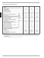
12 Device Information
1
Type and order code
2
Design
2.1
Degree of protection according to EN 60 529 for compact devices and
heating components
2.2
Installation location
3
Performance data
3.1
Operating temperature limits:
LAS 10MT
LAS 15MT
LAS 22TT
IP 24
IP 24
IP 24
Outdoors
Outdoors
Outdoors
English
Heating water flow / return flow 1
°C / °C
Up to 40 / above 10
Up to 40 / above 10
Up to 40 / above 10
Air
°C
-10 to +35
-10 to +35
-10 to +35
kW / kW
22.3 / 4.4
2
3.2
Heat output / power consumption at A20 / W24
12.1 / 2.9
16.6 / 3.5
3.3
Sound power level
dB(A)
70
70
71
3.4
Sound pressure level at a distance of 10 m (air outlet side)dB(A)
45
45
46
3.5
Pool water flow with an internal pressure differential of
m³/h / Pa
1.6 / 7200
2.0 / 12000
2.5 / 8000
R407C / 1.5
R407C / 1.6
R407C / 2.5
1.8
2.4
3.0
H x W x L cm
86 x 127 x 67
86 x 127 x 67
86 x 127 x 67
G 1'' external
G 1'' external
G 1 1/2'' external
147
155
162
3.6
Refrigerant; total filling weight
type / kg
3.7
El. output of defrost heater
kW
4
Dimensions, connections and weight
4.1
Device dimensions
4.2
Device connections to heating system
Inch
4.3
Weight of the transportable unit(s) incl. packing
kg
5
Electrical Connection
5.1
Nominal voltage; fuse protection
5.2
Nominal power consumption 2
5.3
230 / 20
230 / 25
400 / 16
kW
V/A
3.3
4.0
5.1
Starting current with soft starter
A
33
43
25
5.4
Nominal current A15 / W32 / cos ϕ
A / ---
17.0 / 0.8
21.0 / 0.8
10.0 / 0.8
6
Complies with the European safety regulations
3
3
3
7
Additional model features
7.1
Defrosting
Automatic
Automatic
Automatic
Type of defrosting
Electrical
Electrical
Electrical
Yes (heated)
Yes (heated)
Yes (heated)
Yes
Yes
Yes
1
1
1
A15 / W32
Defrosting tray included
Heating water in device protected against icing 4
7.2
7.3
Performance levels
1. See operating limits diagram
2. This data indicates the size and capacity of the system. For an analysis of the economic and energy efficiency of the system, other parameters, such as, in particular, the defrosting
capacity, the bivalence point and regulation, should also be taken into consideration. E.g. A20 / W24 have the following meaning: external air temperature 20°C and swimming
pool flow temperature 24 °C.
3. See CE declaration of conformity
4. The heat circulating pump and the heat pump controller must always be ready for operation.
E-8
Anhang / Appendix / Annexes
1
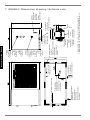
Maßbild / Dimension drawing / Schéma coté ............................................................................ A-II
2
Stromlaufpläne / Circuit diagrams / Schémas électriques ...................................................... A-III
2.1
2.2
2.3
2.4
2.5
2.6
2.7
2.8
3
Steuerung / Control / Commande LAS 10MT - LAS 15MT.................................................................... A-III
Last / Load / Charge LAS 10MT - LAS 15MT ........................................................................................A-III
Anschlussplan / Terminal diagram / Schéma de branchement LAS 10MT - LAS 15MT .......................A-IV
Legende / Legend / Légende LAS 10MT - LAS 15MT............................................................................A-V
Steuerung / Control / Commande LAS 22TT..........................................................................................A-V
Last / Load / Charge LAS 22TT .............................................................................................................A-VI
Anschlussplan / Terminal diagram / Schéma de branchement LAS 22TT ............................................A-VI
Legende / Legend / Légende LAS 22TT...............................................................................................A-VII
Hydraulische Prinzipschemen / Hydraulic block diagrams / Schémas hydrauliques ........ A-VIII
3.1 Darstellung / Schematic view / Représentation schématique..............................................................A-VIII
3.2 Legende / Legend / Légende.................................................................................................................A-IX
Konformitätserklärung / Declaration of Conformity / Déclaration de conformité .................. A-X
Anhang · Appendix · Annexes
4
www.dimplex.de
A-I
A-II
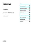
%RvWHGHMRQFWLRQpOHFWULTXH
F{WHUpYLVLRQ
(OHFWUFRQQHFWLRQER[
LQVSHFWLRQVLGH
HOHNWULVFKHU$QVFKOXVVNDVWHQ
5HYLVLRQVVHLWH
(FRXOHPHQWGHO¶HDX
GHFRQGHQVDWLRQ
&RQGHQVDWHGUDLQ
.RQGHQVDWDEODXI
XPODXIHQGFLUFXPIHUHQWLDOFLUFRQIpUHQWLHO
&{WHGHVRXIIODJHG¶DLU
$LUGLVFKDUJHHQG
/XIWDXVEODVVHLWH
6HQVGXILX[G¶DLU
'LUHFWLRQRIDLUIORZ
/XIWULFKWXQJ
*UXQGUDKPHQ%DVHIUDPH&KkVVLV
Anhang · Appendix · Annexes
.RQGHQVDWDEODXI
YHUVFDQDOLVDWLRQ
GHVHDX[XVpHV
WRVHZHU
6RO
6RLO
(UGUHLFK
×SKDVLJH*HUlWH5´SKDVHGHYLFH5³DSSDUHLOVPRQRSKDVpV5´
×SKDVLJH*HUlWH5´SKDVHGHYLFH5´DSSDUHLOVWULSKDVpV5´
WX\DXG¶HDXGH
FRQGHQVDWLRQ
SODVWLTXH
&RQGHQVDWHWXEH
SODVWLF
.RQGHQVDWURKU
.XQVWVWRII
6XUIDFHVG¶DSSXLGH
O¶DSSDUHLO
$SSOLDQFHFRQWDFWVXUIDFHV
VWDLQOHVVVWHHO
3DVVDJHV
OLJQHVpOHFWULTXHV
)HHGWKURXJK
(OHFWULFOLQHV
=XIKUXQJ
(OHNWUROHLWXQJHQ
%DFG¶HDXGHFRQGHQVDWLRQ
&RQGHQVDWHSDQ
.RQGHQVDWZDQQH
]XP
$EZDVVHUNDQDO
(FRXOHPHQWHDX
GHFRQGHQVDWLRQ
&RQGHQVDWHGUDLQ
*HUlWHDXIODJHIOlFKHQ
(GHOVWDKO
UHWRXU
FKDXIIDJH
HQWUpHG¶HDX 5´RX5´
ILOHWDJHH[W
+HDWLQJZDWHU
5HWXUQIORZ
ZDWHULQOHW 5´DQG5´
H[WHUQDOWKUHDG
+HL]ZDVVHU
5FNODXI
:DVVHUHLQWULWW 5´E]Z5´
$XHQJHZLQGH
GpSDUW
FKDXIIDJH
VRUWLHG¶HDX 5´RX5´
ILOHWDJHH[W
+HDWLQJZDWHU
)ORZ
ZDWHURXWOHW 5´DQG5´
H[WHUQDOWKUHDG
+HL]ZDVVHU
9RUODXI
:DVVHUDXVWULWW 5´E]Z5´
$XHQJHZLQGH
1
1 Maßbild / Dimension drawing / Schéma coté
2.2
2.1
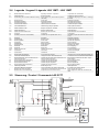
Steuerung / Control / Commande LAS 10MT - LAS 15MT
2.2
Last / Load / Charge LAS 10MT - LAS 15MT
www.dimplex.de
Anhang · Appendix · Annexes
2 Stromlaufpläne / Circuit diagrams / Schémas
électriques
A-III
2.3
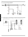
2.3
Anschlussplan / Terminal diagram / Schéma de branchement
LAS 10MT - LAS 15MT
6FKDOWUDXP6ZLWFKER[%RvWHGHGLVWULEXWLRQ
$QVFKOXVVOHLWXQJÂ&RQQHFWLQJOHDGÂ/LJQHGHUDFFRUGHPHQW
JHJQÂ\HJQÂMDYH
1HW]Â0DLQVÂ5pVHDX
Anhang · Appendix · Annexes
A-IV
)LOWHUSXPSHOlXIW
)LOWHUSXPSLVUXQQLQJ
SRPSHGHILOWUDWLRQHQPDUFKH
$QIRUGHUXQJ)LOWHUSXPSH
)LOWHUSXPSUHTXHVW
DFWLYDWLRQSRPSHGHILOWUDWLRQ
2.5
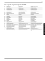
Legende / Legend / Légende LAS 10MT - LAS 15MT
C1
Betriebskondensator-Verdichter
Operating condenser - compressor
Compresseur du condensateur
E4
E11
Düsenringheizung
Abtauheizung (bei LAS 10MT entfällt eine Heizung)
Nozzle ring heater
Defrost heater (Only three heaters required for
LAS 10MT)
Chauffage à faisceau tubulaire
Chauffage de dégivrage (LAS 10MT, un chauffage
de moins)
F1
F4
F5
F23
Steuersicherung
Pressostat Hochdruck
Pressostat Niederdruck
Thermokontakt Ventilator
Control fuse
High-pressure switch
Low-pressure switch
Thermal contact for ventilator
Fusible de commande
Pressostat haute pression
Pressostat basse pression
Contact thermique ventilateur
H1**
Leuchte Betriebsbereit
Indicator lamp, ready for operation
Lampe “prêt à fonctionner”
K1
K14
K27*
Relais Verdichter / Lüfter
Relais Abtauheizung
Relais Anforderung Filterpumpe
Relay for compressor / ventilator
Relay for defrost heater
Relay for filter pump request
Relais compresseur / aérateur
Relais dégivrage
Relais activation pompe de filtration
M1
M2
Verdichter
Ventilator (nicht unter 170V betreiben!)
Compressor
Ventilator (Do not operate below 170 V!)
Compresseur
Ventilateur (ne pas faire fonctionner avec moins de
170 V)
N7
N10
N12
Softstarter
Fernbedienung
Steuerungsplatine
Soft starter
Remote control
Control PCB
Démarreur progressif
Commande à distance
Panneau de commande
R1
R2
R7
R12.1
R12.2
R14**
R15
Außenfühler
Rücklauffühler
Kodierwiderstand
Abtauende
Abtauende
Sollwert Potentiometer
Vorlauffühler
External sensor
Return flow sensor
Coding resistor
Defrost end
Defrost end
Setpoint potentiometer
Flow sensor
Sonde extérieure
Sonde circuit de retour
Résistance de codage
Fin de dégivrage
Fin de dégivrage
Consigne potentiomètre
Sonde circuit de départ
T1
Transformator
Transformer
Transformateur
S1**
S2**
Steuerschalter WP-EIN/AUS
Umschalter HEIZEN/KÜHLEN
Control switch HP ON/OFF
Changeover switch HEATING/COOLING
Interrupteur de commande MARCHE/ARRET PAC
Commutateur CHAUFFAGE/REFROIDISSEMENT
X1
X2
X3
X4
X5
Klemmenleiste Netz- L/N / PE-230VAC-50 Hz /
externe Komponenten
Klemmenleiste externe Verdrahtung
Klemmenleiste Abtauheizungen
Klemmenleiste Verdichter
Klemmenleiste interne Verdrahtung
Terminal strip for power supply L/N/PE-230 V AC50Hz / external components
Terminal strip for external wiring
Terminal strip for defrost heater
Terminal strip for compressor
Terminal strip for internal wiring
Bornier réseau L/N/PE-230V AC-50Hz / composants externes
Bornier câblage extérieur
Bornier dégivrage
Bornier compresseur
Bornier câblage intérieur
––––––
-----*
**
werksseitig verdrahtet
bauseits bei Bedarf anzuschließen
Bauteile sind extern beizustellen
Bauteile sind in der Fernbedienung
Wired ready for use
To be connected by the customer as required
Components to be supplied from external sources
Components are in the remote control
câblé départ usine
à raccorder par le client au besoin
Pièces à fournir par le client
Pièces intégrées au boîtier de commande à distance
2.5
Steuerung / Control / Commande LAS 22TT
www.dimplex.de
A-V
Anhang · Appendix · Annexes
2.4
2.6
2.6
Last / Load / Charge LAS 22TT
1HW]Â0DLQVÂ5pVHDX
<
8PLQ
/LHIHU]XVWDQG
USP
'HOLYHU\FRQGLWLRQV
WPLQ
GpSDUWXVLQH
Anschlussplan / Terminal diagram / Schéma de branchement LAS 22TT
6FKDOWUDXP6ZLWFKER[%RvWHGHGLVWULEXWLRQ
$QVFKOXVVOHLWXQJÂ&RQQHFWLQJOHDGÂ/LJQHGHUDFFRUGHPHQW
JHJQÂ\HJQÂMDYH
1HW]Â0DLQVÂ5pVHDX
Anhang · Appendix · Annexes
2.7
A-VI
)LOWHUSXPSHOlXIW
)LOWHUSXPSLVUXQQLQJ
SRPSHGHILOWUDWLRQHQPDUFKH
$QIRUGHUXQJ)LOWHUSXPSH
)LOWHUSXPSUHTXHVW
DFWLYDWLRQSRPSHGHILOWUDWLRQ
2.8
Legende / Legend / Légende LAS 22TT
E4
E11
Düsenringheizung
Abtauheizung
Nozzle ring heater
Defrost heater
Chauffage à faisceau tubulaire
Dégivrage
F1
F4
F5
F23
Steuersicherung
Pressostat Hochdruck
Pressostat Niederdruck
Thermokontakt Ventilator
Control fuse
High-pressure switch
Low-pressure switch
Thermal contact for ventilator
Fusible de commande
Pressostat haute pression
Pressostat basse pression
Contact thermique ventilateur
H1**
Leuchte Betriebsbereit
Indicator lamp, ready for operation
Lampe “prêt à fonctionner”
K1
K14
K27*
Schütz Verdichter / Lüfter
Schütz Abtauheizung
Relais Anforderung Filterpumpe
Contactor for compressor / ventilator
Contactor for defrost heater
Relay for filter pump request
Contacteur compresseur / aérateur
Contacteur dégivrage
Relais activation pompe de filtration
M1
M2
Verdichter
Ventilator
Compressor
Ventilator
Compresseur
Ventilateur
N7
N10
N12
Softstarter
Fernbedienung
Steuerungsplatine
Soft starter
Remote control
Control PCB
Démarreur progressif
Commande à distance
Panneau de commande
R1
R2
R7
R12.1
R12.2
R14**
R15
Außenfühler
Rücklauffühler
Kodierwiderstand
Abtauende
Abtauende
Sollwert Potentiometer
Vorlauffühler
External sensor
Return flow sensor
Coding resistor
Defrost end
Defrost end
Setpoint potentiometer
Flow sensor
Sonde extérieure
Sonde circuit de retour
Résistance de codage
Fin de dégivrage
Fin de dégivrage
Consigne potentiomètre
Sonde circuit de départ
S1**
S2**
Steuerschalter WP-EIN/AUS
Umschalter HEIZEN/KÜHLEN
Control switch HP ON/OFF
Changeover switch HEATING/COOLING
Interrupteur de commande MARCHE/ARRET PAC
Commutateur CHAUFFAGE/REFROIDISSEMENT
X1
X2
X3
X5
Klemmenleiste Netz- ~3/N/PE - 400 V AC / 50 Hz
Klemmenleiste externe Verdrahtung
Klemmenleiste Abtauheizungen
Klemmenleiste interne Verdrahtung
Terminal strip for mains ~3/N/PE - 400 V AC / 50 Hz
Terminal strip for external wiring
Terminal strip for defrost heaters
Terminal strip for internal wiring
Bornier réseau - ~3/N/PE - 400 V AC / 50 Hz
Bornier câblage extérieur
Bornier dégivrage
Bornier câblage intérieur
––––––
-----*
**
werksseitig verdrahtet
bauseits bei Bedarf anzuschließen
Bauteile sind extern beizustellen
Bauteile sind in der Fernbedienung
Wired ready for use
To be connected by the customer as required
Components to be supplied from external sources
Components are in the remote control
câblé départ usine
à raccorder par le client au besoin
Pièces à fournir par le client
Pièces intégrées au boîtier de commande à distance
www.dimplex.de
A-VII
Anhang · Appendix · Annexes
2.8
3
3 Hydraulische Prinzipschemen / Hydraulic block
diagrams / Schémas hydrauliques
3.1
Anhang · Appendix · Annexes
A-VIII
Darstellung / Schematic view / Représentation schématique
3.2
3.2
Legende / Legend / Légende
Circulating pump
Pompe de circulation
Absperrventil mit Entwässerung
Shutoff valve with drainage
Vanne d’arrêt et évacuation de l’eau
Temperaturfühler
Temperature sensor
Sonde de température
Flexibler Anschlussschlauch
Flexible connection hose
Tuyau de raccordement
Luft/Wasser-Wärmepumpe
Air-to-water heat pump
PAC air/eau
offener Wasserspeicher (Bassin)
Open water storage (basin)
Réservoir d’eau à ciel ouvert (bassin)
Filteranlage
Filter system
Installation de filtration
Wasseraufbereitung
Water treatment
Installation de traitement de l’eau
N10
Fernversteller - für Innenraummontage
Remote control - for interior installation
Régleur à distance - pour montage intérieur
R1
Außenfühler
External sensor
Sonde extérieure
R2
Rücklauffühler
Return flow sensor
Sonde du circuit de retour
R15
Vorlauffühler
Flow sensor
Sonde du circuit de départ
EV
Elektroverteilung
Electrical distribution system
Distribution électrique
Je nach Einsatzfall und Aufstellungsort ist der
Einsatz zusätzlicher Absperr- und Regelventile
in der Nähe der Wärmepumpe empfehlenswert.
Depending on the installation location and application, we recommend installing additional shutoff valves and control valves in the vicinity of the
heat pump according to need.
Suivant le type d’utilisation et l’emplacement,
l’emploi de vannes d’arrêt et de régulation supplémentaires au droit de la PAC est recommandé.
www.dimplex.de
Anhang · Appendix · Annexes
Umwälzpumpe
A-IX
4
4 Konformitätserklärung / Declaration of Conformity /
Déclaration de conformité
Anhang · Appendix · Annexes
A-X
Glen Dimplex Deutschland GmbH
Geschäftsbereich Dimplex
Am Goldenen Feld 18
D-95326 Kulmbach
Irrtümer und Änderungen vorbehalten.
Subject to alterations and errors.
Sous réserve d’erreurs et modifications.
+49 (0) 9221 709 565
www.dimplex.de