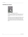
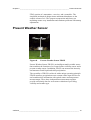
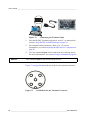
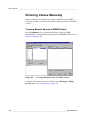
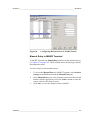
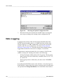
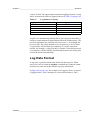
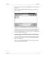
1
Vaisala HydroMet™ System
MAWS301
USER'S GUIDE
M210662EN-A
November 2004
PUBLISHED BY
Vaisala Oyj
Phone (int.):
+358 9 8949 1
P.O. Box 26
Fax:
+358 9 8949 2227
FIN-00421 Helsinki
Finland
Visit our Internet pages at http://www.vaisala.com/
© Vaisala 2004
No part of this manual may be reproduced in any form or by any means,
electronic or mechanical (including photocopying), nor may its contents
be communicated to a third party without prior written permission of the
copyright holder.
The contents are subject to change without prior notice.
Please observe that this manual does not create any legally binding
obligations for Vaisala towards the customer or end user. All legally
binding commitments and agreements are included exclusively in the
applicable supply contract or Conditions of Sale.
________________________________________________________________________________
Table of Contents
CHAPTER 1
GENERAL INFORMATION . . . . . . . . . . . . . . . . . . . . . . . . . . . . . . . . . . . . . . 7
About This Manual . . . . . . . . . . . . . . . . . . . . . . . . . . . . . . . . . 7
Contents of This Manual . . . . . . . . . . . . . . . . . . . . . . . . . . . 7
Safety . . . . . . . . . . . . . . . . . . . . . . . . . . . . . . . . . . . . . . . . . . . . 8
General Safety Considerations . . . . . . . . . . . . . . . . . . . . . . 8
Product Related Safety Precautions . . . . . . . . . . . . . . . . . . 8
ESD Protection . . . . . . . . . . . . . . . . . . . . . . . . . . . . . . . . . 10
Trademarks . . . . . . . . . . . . . . . . . . . . . . . . . . . . . . . . . . . . . . 10
License Agreement . . . . . . . . . . . . . . . . . . . . . . . . . . . . . . . . 10
Warranty . . . . . . . . . . . . . . . . . . . . . . . . . . . . . . . . . . . . . . . . 10
CHAPTER 2
PRODUCT OVERVIEW . . . . . . . . . . . . . . . . . . . . . . . . . . . . . . . . . . . . . . . 11
Vaisala HydroMet™ System MAWS301 . . . . . . . . . . . . . . . 11
Product Nomenclature . . . . . . . . . . . . . . . . . . . . . . . . . . . . . 13
AWS Logger . . . . . . . . . . . . . . . . . . . . . . . . . . . . . . . . . . . . . . 17
A Wall Adapter . . . . . . . . . . . . . . . . . . . . . . . . . . . . . . . . . . 20
MAWS Software . . . . . . . . . . . . . . . . . . . . . . . . . . . . . . . . . . . 20
Operating Software . . . . . . . . . . . . . . . . . . . . . . . . . . . . . . 20
MAWS Terminal . . . . . . . . . . . . . . . . . . . . . . . . . . . . . . . . . 20
MAWS Lizard Setup Software . . . . . . . . . . . . . . . . . . . . . . 21
Enclosure . . . . . . . . . . . . . . . . . . . . . . . . . . . . . . . . . . . . . . . . 21
Accessories . . . . . . . . . . . . . . . . . . . . . . . . . . . . . . . . . . . . . . 23
Sensor Multiplexer . . . . . . . . . . . . . . . . . . . . . . . . . . . . . . . 23
Digital I/O Module . . . . . . . . . . . . . . . . . . . . . . . . . . . . . . . 24
GPS Time Synchronizing Unit . . . . . . . . . . . . . . . . . . . . . . 25
Masts . . . . . . . . . . . . . . . . . . . . . . . . . . . . . . . . . . . . . . . . . 25
Sensor Support . . . . . . . . . . . . . . . . . . . . . . . . . . . . . . . . . 27
AC (Mains) Power Supply . . . . . . . . . . . . . . . . . . . . . . . . . 28
Transient Protection Devices . . . . . . . . . . . . . . . . . . . . . . . 29
Power Supply . . . . . . . . . . . . . . . . . . . . . . . . . . . . . . . . . . . . 30
Solar Panels . . . . . . . . . . . . . . . . . . . . . . . . . . . . . . . . . . . . . 31
SOLAR12-75 . . . . . . . . . . . . . . . . . . . . . . . . . . . . . . . . . . . 31
SOLAR24 . . . . . . . . . . . . . . . . . . . . . . . . . . . . . . . . . . . . . . 32
RS-232 Module . . . . . . . . . . . . . . . . . . . . . . . . . . . . . . . . . . . 33
RS-485 Modules . . . . . . . . . . . . . . . . . . . . . . . . . . . . . . . . . . 34
Introduction to DSI485A . . . . . . . . . . . . . . . . . . . . . . . . . . . 34
Introduction to DSI486 . . . . . . . . . . . . . . . . . . . . . . . . . . . . 34
Modem Module . . . . . . . . . . . . . . . . . . . . . . . . . . . . . . . . . . . 35
VAISALA ________________________________________________________________________ 1
User’s Guide ______________________________________________________________________
PSTN Modem
. . . . . . . . . . . . . . . . . . . . . . . . . . . . . . . . . . . .36
GSM Terminal Module . . . . . . . . . . . . . . . . . . . . . . . . . . . . . .37
UHF Radio Modem . . . . . . . . . . . . . . . . . . . . . . . . . . . . . . . .39
Repeater Function . . . . . . . . . . . . . . . . . . . . . . . . . . . . . . .40
UHF Antenna . . . . . . . . . . . . . . . . . . . . . . . . . . . . . . . . . . .41
ORBCOMM Satellite Transceiver Set . . . . . . . . . . . . . . . . .42
GOES Satellite Transmitters . . . . . . . . . . . . . . . . . . . . . . . .44
GOES Crossed Yagi Antenna . . . . . . . . . . . . . . . . . . . . . .45
GPS Antenna . . . . . . . . . . . . . . . . . . . . . . . . . . . . . . . . . . .45
Ultrasonic Wind Sensor . . . . . . . . . . . . . . . . . . . . . . . . . . . .46
Combined Wind Sensor . . . . . . . . . . . . . . . . . . . . . . . . . . . .48
Anemometers . . . . . . . . . . . . . . . . . . . . . . . . . . . . . . . . . . . .49
Introduction to Anemometer . . . . . . . . . . . . . . . . . . . . . . . .49
Introduction to Heated Anemometer . . . . . . . . . . . . . . . . .50
Wind Vanes . . . . . . . . . . . . . . . . . . . . . . . . . . . . . . . . . . . . . .51
Introduction to Wind Vane . . . . . . . . . . . . . . . . . . . . . . . . .51
Introduction to Heated Wind Vane . . . . . . . . . . . . . . . . . . .52
Wind Transmitter . . . . . . . . . . . . . . . . . . . . . . . . . . . . . . . . . .52
Digital Wind Transmitter . . . . . . . . . . . . . . . . . . . . . . . . . . .52
Air Temperature and Relative Humidity Sensor . . . . . . . . .53
Pressure Sensor . . . . . . . . . . . . . . . . . . . . . . . . . . . . . . . . . .53
Rain Gauges . . . . . . . . . . . . . . . . . . . . . . . . . . . . . . . . . . . . .54
Rain Detector . . . . . . . . . . . . . . . . . . . . . . . . . . . . . . . . . . . . .57
Ultrasonic Snow Level Sensor . . . . . . . . . . . . . . . . . . . . . . .58
Solar Radiation Sensors . . . . . . . . . . . . . . . . . . . . . . . . . . . .58
Net Radiometer . . . . . . . . . . . . . . . . . . . . . . . . . . . . . . . . . . .61
Net Solar Radiation Sensor . . . . . . . . . . . . . . . . . . . . . . . . .63
Soil/Water Temperature Sensor . . . . . . . . . . . . . . . . . . . . . .64
Soil Temperature Sensor . . . . . . . . . . . . . . . . . . . . . . . . . . .65
Soil Moisture Sensor . . . . . . . . . . . . . . . . . . . . . . . . . . . . . . .66
Soil Moisture Sensor . . . . . . . . . . . . . . . . . . . . . . . . . . . . . . .67
Leaf Wetness Sensor . . . . . . . . . . . . . . . . . . . . . . . . . . . . . .68
Fuel Moisture/Fuel Temperature Sensor . . . . . . . . . . . . . . .68
Visibility Sensors . . . . . . . . . . . . . . . . . . . . . . . . . . . . . . . . .69
Present Weather Detectors . . . . . . . . . . . . . . . . . . . . . . . . .70
Ceilometer . . . . . . . . . . . . . . . . . . . . . . . . . . . . . . . . . . . . . . .71
Visibility Sensor . . . . . . . . . . . . . . . . . . . . . . . . . . . . . . . . . .72
Present Weather Sensor . . . . . . . . . . . . . . . . . . . . . . . . . . . .73
CHAPTER 3
OPERATION . . . . . . . . . . . . . . . . . . . . . . . . . . . . . . . . . . . . . . . . . . . . . . . .75
Operation Principle . . . . . . . . . . . . . . . . . . . . . . . . . . . . . . . .75
Taking MAWS into Use . . . . . . . . . . . . . . . . . . . . . . . . . . . . .76
Aligning Wind Vane . . . . . . . . . . . . . . . . . . . . . . . . . . . . . .76
2 ____________________________________________________________________M210662EN-A
________________________________________________________________________________
Using winddircal0 Command . . . . . . . . . . . . . . . . . . . . 76
Using Compass and Reference Point . . . . . . . . . . . . . 76
Setting Up Solar Panel . . . . . . . . . . . . . . . . . . . . . . . . . . . . 77
Quick Start Instructions . . . . . . . . . . . . . . . . . . . . . . . . . . . 79
Establishing Terminal Connection . . . . . . . . . . . . . . . . . . . 79
Using MAWS Terminal Software . . . . . . . . . . . . . . . . . . . . . 81
Selecting the Language . . . . . . . . . . . . . . . . . . . . . . . . . . . 81
MAWS Terminal Main Window . . . . . . . . . . . . . . . . . . . . . 82
Defining MAWS Terminal Settings . . . . . . . . . . . . . . . . . . . 84
Preferences Window . . . . . . . . . . . . . . . . . . . . . . . . . . 84
Address Book Window. . . . . . . . . . . . . . . . . . . . . . . . . 86
Opening MAWS Service Connection . . . . . . . . . . . . . . . . . 87
Giving Commands . . . . . . . . . . . . . . . . . . . . . . . . . . . . . . . 89
Closing MAWS Service Connection . . . . . . . . . . . . . . . . . . 90
Managing User Levels . . . . . . . . . . . . . . . . . . . . . . . . . . . . 90
Modifying Station Settings . . . . . . . . . . . . . . . . . . . . . . . . . . 92
Setting Static Parameters . . . . . . . . . . . . . . . . . . . . . . . . . 93
Calibrating Sensors . . . . . . . . . . . . . . . . . . . . . . . . . . . . . . 96
Sensor Status List . . . . . . . . . . . . . . . . . . . . . . . . . . . . 99
Entering Values Manually . . . . . . . . . . . . . . . . . . . . . . . . 100
Creating Manual Sensor in MAWS Lizard . . . . . . . . . 100
Manual Entry in MAWS Terminal. . . . . . . . . . . . . . . . 101
MAWS Configuration File . . . . . . . . . . . . . . . . . . . . . . . . . . 102
Selecting Configuration File . . . . . . . . . . . . . . . . . . . . . . . 102
Uploading Configuration File . . . . . . . . . . . . . . . . . . . . . . 103
Data Logging . . . . . . . . . . . . . . . . . . . . . . . . . . . . . . . . . . . . 104
Log Data Format . . . . . . . . . . . . . . . . . . . . . . . . . . . . . . . 105
Controlling Logging . . . . . . . . . . . . . . . . . . . . . . . . . . . . . 106
Measurement Enable or Disable . . . . . . . . . . . . . . . . . . . 107
Freeing Up Logging Space . . . . . . . . . . . . . . . . . . . . . . . 109
Working with Data Log Files . . . . . . . . . . . . . . . . . . . . . . 109
Selecting Files for Downloading. . . . . . . . . . . . . . . . . 110
Downloading Files . . . . . . . . . . . . . . . . . . . . . . . . . . . 111
Autodownloading Log Files . . . . . . . . . . . . . . . . . . . . 112
Browsing Downloaded Files. . . . . . . . . . . . . . . . . . . . 116
Converting One Data Log File to CSV Format. . . . . . 118
Converting Several Data Log Files to CSV Format . . 119
Using External Memory Card . . . . . . . . . . . . . . . . . . . . . . . 120
Automatic Erase from External Memory Card . . . . . . . . . 121
Resetting MAWS . . . . . . . . . . . . . . . . . . . . . . . . . . . . . . . . . 122
Command Reference for Terminal Connection . . . . . . . . 123
CHAPTER 4
MAINTENANCE . . . . . . . . . . . . . . . . . . . . . . . . . . . . . . . . . . . . . . . . . . . . 127
Routine Maintenance and Calibration . . . . . . . . . . . . . . . . 127
Overall Checking . . . . . . . . . . . . . . . . . . . . . . . . . . . . . . . . . 129
Cable Maintenance . . . . . . . . . . . . . . . . . . . . . . . . . . . . . . . 129
Updating Software to the Logger . . . . . . . . . . . . . . . . . . . 129
Spare Parts . . . . . . . . . . . . . . . . . . . . . . . . . . . . . . . . . . . . . 131
VAISALA ________________________________________________________________________ 3
User’s Guide ______________________________________________________________________
Available Spare Parts . . . . . . . . . . . . . . . . . . . . . . . . . . . .131
Ordering Spare Parts . . . . . . . . . . . . . . . . . . . . . . . . . . . .131
Solar Panel . . . . . . . . . . . . . . . . . . . . . . . . . . . . . . . . . . . . . .132
Periodic Maintenance . . . . . . . . . . . . . . . . . . . . . . . . . . . .132
Ultrasonic Wind Sensor . . . . . . . . . . . . . . . . . . . . . . . . . . .132
Periodic Maintenance . . . . . . . . . . . . . . . . . . . . . . . . . . . .132
Combined Wind Sensor . . . . . . . . . . . . . . . . . . . . . . . . . . .134
Periodic Maintenance . . . . . . . . . . . . . . . . . . . . . . . . . . . .134
Testing Proper Operation. . . . . . . . . . . . . . . . . . . . . . 134
Replacing Consumables . . . . . . . . . . . . . . . . . . . . . . 134
Anemometers . . . . . . . . . . . . . . . . . . . . . . . . . . . . . . . . . . .137
Periodic Maintenance . . . . . . . . . . . . . . . . . . . . . . . . . . . .137
Cleaning . . . . . . . . . . . . . . . . . . . . . . . . . . . . . . . . . . . 137
Testing Proper Operation. . . . . . . . . . . . . . . . . . . . . . 137
Replacing Bearings of WAA151. . . . . . . . . . . . . . . . . 137
Replacing Bearings of WAA252. . . . . . . . . . . . . . . . . 141
Wind Vanes . . . . . . . . . . . . . . . . . . . . . . . . . . . . . . . . . . . . .144
Periodic Maintenance . . . . . . . . . . . . . . . . . . . . . . . . . . . .144
Cleaning . . . . . . . . . . . . . . . . . . . . . . . . . . . . . . . . . . . 144
Testing Proper Operation. . . . . . . . . . . . . . . . . . . . . . 144
Replacing Bearings of WAV151. . . . . . . . . . . . . . . . . 144
Replacing Bearings of WAV252. . . . . . . . . . . . . . . . . 148
Wind Transmitter . . . . . . . . . . . . . . . . . . . . . . . . . . . . . . . . .152
Periodic Maintenance . . . . . . . . . . . . . . . . . . . . . . . . . . . .152
Air Temperature and Relative Humidity Sensor . . . . . . . .152
Periodic Maintenance . . . . . . . . . . . . . . . . . . . . . . . . . . . .152
Changing the HUMICAP®180 Humidity Sensor . . . . 153
Humidity Calibration . . . . . . . . . . . . . . . . . . . . . . . . . . 153
Pressure Sensor . . . . . . . . . . . . . . . . . . . . . . . . . . . . . . . . .155
Periodic Maintenance . . . . . . . . . . . . . . . . . . . . . . . . . . . .155
Calibration . . . . . . . . . . . . . . . . . . . . . . . . . . . . . . . . . . . .155
Rain Gauges . . . . . . . . . . . . . . . . . . . . . . . . . . . . . . . . . . . .156
Periodic Maintenance of QMR102 . . . . . . . . . . . . . . . . . .156
Periodic Maintenance of RG13/RG13H . . . . . . . . . . . . . .157
Rain Detector . . . . . . . . . . . . . . . . . . . . . . . . . . . . . . . . . . . .157
Periodic Maintenance . . . . . . . . . . . . . . . . . . . . . . . . . . . .157
Ultrasonic Snow Level Sensor . . . . . . . . . . . . . . . . . . . . . .157
Solar Radiation Sensors . . . . . . . . . . . . . . . . . . . . . . . . . . .158
Periodoc Maintenance of QMS101/QMS102 . . . . . . . . . .158
Periodic Maintenance of CM Series Sensors . . . . . . . . . .158
Net Radiometer . . . . . . . . . . . . . . . . . . . . . . . . . . . . . . . . . .159
Periodic Maintenance . . . . . . . . . . . . . . . . . . . . . . . . . . . .159
Net Solar Radiation Sensor . . . . . . . . . . . . . . . . . . . . . . . .159
Periodic Maintenance . . . . . . . . . . . . . . . . . . . . . . . . . . . .159
Soil/Water Temperature Sensors . . . . . . . . . . . . . . . . . . . .159
Periodic Maintenance . . . . . . . . . . . . . . . . . . . . . . . . . . . .159
Soil Moisture Sensor . . . . . . . . . . . . . . . . . . . . . . . . . . . . . .160
Periodic Maintenance . . . . . . . . . . . . . . . . . . . . . . . . . . . .160
4 ____________________________________________________________________M210662EN-A
________________________________________________________________________________
Soil Moisture Sensor . . . . . . . . . . . . . . . . . . . . . . . . . . . . . 160
Periodic Maintenance . . . . . . . . . . . . . . . . . . . . . . . . . . . 160
Leaf Wetness Sensor . . . . . . . . . . . . . . . . . . . . . . . . . . . . . 161
Periodic Maintenance . . . . . . . . . . . . . . . . . . . . . . . . . . . 161
Fuel Moisture/Fuel Temperature Sensor . . . . . . . . . . . . . 161
Periodic Maintenance . . . . . . . . . . . . . . . . . . . . . . . . . . . 161
Present Weather Detector . . . . . . . . . . . . . . . . . . . . . . . . . 161
Periodic Maintenance . . . . . . . . . . . . . . . . . . . . . . . . . . . 161
Cleaning Lenses and Hoods . . . . . . . . . . . . . . . . . . . 162
Cleaning DRD Rain Detector . . . . . . . . . . . . . . . . . . . 163
Ceilometer . . . . . . . . . . . . . . . . . . . . . . . . . . . . . . . . . . . . . . 163
Present Weather Sensor . . . . . . . . . . . . . . . . . . . . . . . . . . . 163
Periodic Maintenance . . . . . . . . . . . . . . . . . . . . . . . . . . . 163
CHAPTER 5
TROUBLESHOOTING . . . . . . . . . . . . . . . . . . . . . . . . . . . . . . . . . . . . . . . 165
Basic Procedure for Troubleshooting . . . . . . . . . . . . . . . . 165
Visual Check . . . . . . . . . . . . . . . . . . . . . . . . . . . . . . . . . . . . 170
Determining MAWS Operation Mode . . . . . . . . . . . . . . . . 172
Establishing Terminal Connection . . . . . . . . . . . . . . . . . . 172
Recording Terminal Connection Text . . . . . . . . . . . . . . . 174
Opening Service Connection Through MAWS . . . . . . . . . 174
Connection Problems . . . . . . . . . . . . . . . . . . . . . . . . . . . . 175
Error Messages . . . . . . . . . . . . . . . . . . . . . . . . . . . . . . . . 176
Resetting MAWS . . . . . . . . . . . . . . . . . . . . . . . . . . . . . . . . . 177
Determining Sensor Status . . . . . . . . . . . . . . . . . . . . . . . . 177
Using External Memory Card . . . . . . . . . . . . . . . . . . . . . . . 181
Automatic Erase from External Memory Card . . . . . . . . . 182
Commands for Troubleshooting Purposes . . . . . . . . . . . 182
LASTVAL Command . . . . . . . . . . . . . . . . . . . . . . . . . . . . 183
Warnings and Errors . . . . . . . . . . . . . . . . . . . . . . . . . . . . 184
System Information . . . . . . . . . . . . . . . . . . . . . . . . . . . . . 186
Battery Status . . . . . . . . . . . . . . . . . . . . . . . . . . . . . . . . . 187
Measurement Enable or Disable . . . . . . . . . . . . . . . . . . . 188
Battery Regulator . . . . . . . . . . . . . . . . . . . . . . . . . . . . . . . . 189
Power Supply . . . . . . . . . . . . . . . . . . . . . . . . . . . . . . . . . . . 189
Replacing Fuses . . . . . . . . . . . . . . . . . . . . . . . . . . . . . . . 189
Solar Panel . . . . . . . . . . . . . . . . . . . . . . . . . . . . . . . . . . . . . 191
GSM Modems . . . . . . . . . . . . . . . . . . . . . . . . . . . . . . . . . . . 191
GOES Satellite Transmitter . . . . . . . . . . . . . . . . . . . . . . . . 192
Ultrasonic Wind Sensor . . . . . . . . . . . . . . . . . . . . . . . . . . . 192
Combined Wind Sensor . . . . . . . . . . . . . . . . . . . . . . . . . . . 192
Anemometers . . . . . . . . . . . . . . . . . . . . . . . . . . . . . . . . . . . 193
Wind Vanes . . . . . . . . . . . . . . . . . . . . . . . . . . . . . . . . . . . . . 194
Wind Transmitter . . . . . . . . . . . . . . . . . . . . . . . . . . . . . . . . . 195
Air Temperature and Relative Humidity Sensor . . . . . . . . 196
VAISALA ________________________________________________________________________ 5
User’s Guide ______________________________________________________________________
Present Weather Detector . . . . . . . . . . . . . . . . . . . . . . . . .196
Present Weather Sensor . . . . . . . . . . . . . . . . . . . . . . . . . . .197
Ceilometer . . . . . . . . . . . . . . . . . . . . . . . . . . . . . . . . . . . . . .198
Technical Support . . . . . . . . . . . . . . . . . . . . . . . . . . . . . . . .198
Return Instructions . . . . . . . . . . . . . . . . . . . . . . . . . . . . . . .199
APPENDIX A
GLOSSARY . . . . . . . . . . . . . . . . . . . . . . . . . . . . . . . . . . . . . . . . . . . . . . . .201
6 ____________________________________________________________________M210662EN-A
Chapter 1 ________________________________________________________ General Information
CHAPTER 1
GENERAL INFORMATION
This chapter provides general notes for the product and this manual.
About This Manual
This manual provides information for Vaisala HydroMet™ System
MAWS301 equipped with meteorological and/or hydrological sensors.
Contents of This Manual
This manual consists of the following chapters:
-
Chapter 1, General Information: This chapter provides general
notes for the product and this manual.
-
Chapter 2, Product Overview: This chapter introduces the features,
accessories, sensors, and the product nomenclature.
-
Chapter 3, Operation: This chapter provides the instructions for
taking MAWS into use when all the equipment has been assembled
and installed, as well as operating instructions for the MAWS
Terminal software.
-
Chapter 4, Maintenance: This chapter provides information that is
needed in the basic maintenance of MAWS, sensors, and
accessories.
-
Chapter 5, Troubleshooting: This section consists of some
common MAWS problems, their probable causes, and remedies.
VAISALA ________________________________________________________________________ 7
User’s Guide ______________________________________________________________________
-
Appendix A, Glossary: This appendix contains glossary with
explanations of some general meteorological and technical terms
and terms used in specifications.
Safety
General Safety Considerations
Throughout the manual, important safety considerations are highlighted
as follows:
WARNING
Warning alerts you to a serious hazard. If you do not read and follow
instructions very carefully at this point, there is a risk of injury or even
death.
CAUTION
Caution warns you of a potential hazard. If you do not read and follow
instructions carefully at this point, the product could be damaged or
important data could be lost.
NOTE
Note highlights important information on using the product.
Product Related Safety Precautions
MAWS has been tested for safety and approved as shipped from the
factory. The following safety precautions are not related to any specific
procedures and therefore do not appear elsewhere in this manual. They
are recommended precautions that personnel must understand and
apply during different phases of operation and maintenance.
WARNING
Keep away from live circuits. Operating personnel must observe safety
regulations at all times. Component replacement or internal
adjustments must be made by qualified maintenance personnel. Do not
replace components with the power cable connected. Under certain
conditions, dangerous voltages may exist for some time even with the
power cable disconnected. To avoid injuries, disconnect power and
discharge circuits before touching them.
8 ____________________________________________________________________M210662EN-A
Chapter 1 ________________________________________________________ General Information
WARNING
Do not service alone. Under no circumstances should any person reach
into parts and assemblies that are mains powered and alive, for the
purpose of servicing, except in the presence of someone who is
capable of rendering aid.
WARNING
Personnel working with or near high voltages should be familiar with
modern methods of resuscitation.
WARNING
Do not service a live system outdoors. Do not open units outdoors
when the enclosure contains line voltage levels.
WARNING
Do not operate in an explosive atmosphere, for example, when
flammable gases or fumes are present. Operation of any electrical
instrument in such an environment constitutes a definite safety hazard.
WARNING
Do not substitute parts or modify the instrument. Because of the
danger of introducing additional hazards, do not install unsuitable
parts in the instrument. Contact Vaisala or its authorized representative
for repairs to ensure that safety features are maintained.
WARNING
Be careful when erecting the mast. See that there are no power lines or
other obstacles above the mast.
WARNING
Secure the mast properly to prevent it from falling. Tighten all the
adjustment screws securely.
CAUTION
Do not make changes to the wiring. Incorrect wiring can damage the
device and prevent it from operating correctly.
NOTE
When disposing of old batteries, be sure to do so in accordance with
all regulations applicable in your area.
VAISALA ________________________________________________________________________ 9
User’s Guide ______________________________________________________________________
ESD Protection
Electrostatic Discharge (ESD) can cause immediate or latent damage to
electronic circuits. Vaisala products are adequately protected against
ESD for their intended use. However, it is possible to damage the
product by delivering electrostatic discharges when touching,
removing, or inserting any objects inside the equipment housing.
To make sure you are not delivering high static voltages yourself:
-
Handle ESD sensitive components on a properly grounded and
protected ESD workbench. When this is not possible, ground
yourself with a wrist strap and a resistive connection cord to the
equipment chassis before touching the boards. When neither of the
above is possible, at least touch a conductive part of the equipment
chassis with your other hand before touching the boards.
-
Always hold the boards by the edges and avoid touching the
component contacts.
Trademarks
Microsoft®, Windows®, Windows NT®, and Windows® 2000 are
registered trademarks of Microsoft Corporation in the United States
and/or other countries.
License Agreement
All rights to any software are held by Vaisala or third parties. The
customer is allowed to use the software only to the extent that is
provided by the applicable supply contract or Software License
Agreement.
Warranty
For certain products Vaisala normally gives a limited one-year
warranty. Please observe that any such warranty may not be valid in
case of damage due to normal wear and tear, exceptional operating
conditions, negligent handling or installation, or unauthorized
modifications. Please see the applicable supply contract or Conditions
of Sale for details of the warranty for each product.
10 ___________________________________________________________________M210662EN-A
Chapter 2 __________________________________________________________ Product Overview
CHAPTER 2
PRODUCT OVERVIEW
This chapter introduces the features, accessories, sensors, and the
product nomenclature.
Vaisala HydroMet™ Systems include compact stations that can be used
either with a portable tripod (MAWS201) or with pole masts of
different heights in fixed installations (MAWS101 and MAWS301).
The station comes with a set of sensors, that measure certain
meteorological and/or hydrological quantities and that have been
especially selected for use with Vaisala HydroMet™ Systems.
Vaisala HydroMet™ System MAWS301
Vaisala HydroMet™ System MAWS301 is a new generation AWS
especially designed for applications where no commercial power or
communication networks are present, or are too expensive to be
installed. Due to its flexibility and economical design, MAWS301 is
also an ideal choice for hydro meteorological and hydrological
applications. The possibility to use the same and standard equipment for
many different requirements lowers the cost of training, spare parts, and
logistic support.
MAWS301 has been designed for applications where only a few
sensors are required. However, MAWS301 can be easily upgraded,
even in the field, to include a larger set of sensors including smart
sensors such as ceilometer, visibility and present weather sensors, and
water quality probes. The same basic system with its options and
accessories can provide with all the needs of meteorological and
VAISALA _______________________________________________________________________ 11
User’s Guide ______________________________________________________________________
hydrological networks. The MAWS301 options are listed in Table 5 on
page 15, Table 4 on page 15, and Table 3 on page 14.
The system setup is done using MAWS Lizard Setup Software. In
addition, there are some generic sensor inputs in the Lizard software,
allowing for limited flexibility to add new sensors to the system.
The system configuration can vary from small hydrological systems
(see Figure 1 on page 12) to large integrated systems (see Figure 2 on
page 13).
Figure 1
0101-010
Hydrological System
MAWS301 is easy to install and maintain. All connections are made
using pre-wired connections. The sensors are equipped with readymade cables and connectors/glands for quick installation. All optional
modules such as battery regulator, AC power supply, and surge
arrestors are easily mounted on a DIN rail inside an enclosure.
12 ___________________________________________________________________M210662EN-A
Chapter 2 __________________________________________________________ Product Overview
Figure 2
0410-003
Integrated System
Product Nomenclature
The following tables provide the equipment nomenclature.
Table 1
MAWS301 Basic Set
Code
Common Name
MAWS Lizard
MAWS Terminal
MAWS YourVIEW
QBR101B
QCD101
QML201
ENC542PLM
Setup software
MAWS Terminal software
Graphical Display Software (Basic version)
Battery regulator
CD containing software and documentation
AWS Logger
Equipment enclosure
VAISALA _______________________________________________________________________ 13
User’s Guide ______________________________________________________________________
Table 2
Installation Accessories
Code
Common Name
DKP102
DKP12SUP1
DKP12SUP2
DKP060SUP1
DKP075SUP1
DKP202W
DKP203W
DKP204W
DKP206W
DKP210W
PLMLOCKSET
RG35003
2-meter (6.6 ft.) pole mast
Sensor support arm (half length)
Sensor support arm (full length)
Sensor support arm (half length)
Sensor support arm (half length)
2-meter (6.6 ft.) pole mast
3-meter (10 ft.) pole mast
4-meter (13 ft.) pole mast
6-meter (20 ft.) pole mast
10-meter (33 ft.) pole mast
Two locks with keys for ENC542PLM
Stand for QMR102 and RG13(H), total height with
sensor 1.5 m (5 ft.)
Base plate for QMR102, for installation on ground
RGB1
Table 3
Optional Accessories
Code
Common Name
26588
MGP150
QMBATT7
QMBATT12
QMBATT26
QMBATT52
QMD170
QMD201, QMD202
QMG101
QMI108
SOLAR12
SOLAR24
WHP25
WT521
32 MB Compact Flash memory card
Mains power supply (for outdoor use)
Backup battery, 12 V, 7 Ah
Backup battery, 12 V, 12 Ah
Backup battery set, 12 V, 26 Ah
Backup battery set, 12 V, 52 Ah
Handheld Display
Fixed Display/Keypad
GPS Time synchronizing unit
Digital I/O unit
12 W solar panel
24 W solar panel
AC power supply for wind sensors
Digital wind transmitter
14 ___________________________________________________________________M210662EN-A
Chapter 2 __________________________________________________________ Product Overview
Table 4
Communication Options
Code
Common Name
DMX501
DSI485A
DSI486
DSU232
DXM421
MC35
TC35i
INMARSAT-C
SATEL3ASET-M3
QRC101
QST102
Modem module (fixed line)
RS-485 module (isolated)
RS-485/RS-232/SDI-12 module (dual-isolated)
RS-232 module (dual)
PSTN modem
GSM data modem with GPRS functionality
GSM data modem
Inmarsat satellite transmitter set
Radio modem SATELLINE 3AS with accessories
ORBCOMM Satellite transceiver set
GOES Satellite transmitter interface
Table 5
Sensor Options
Code
Common Name
CM11
CM6B
CM7B
CNR1
CT25K
DCU7110
DCU7210
DRD11A
DSU12
DTR502
ECH2O-M3
FD12
FD12P
HMP45
ML2x
PMT16A
PR36W
PWD10
PWD12
PWD20
PWD22
QFM101
QHB101
QHR102
QLW101
QMH102
QMH110
Solar radiation sensor
Solar radiation sensor
Albedometer
Net Radiometer
Ceilometer
Water level sensor
Snow level sensor
Rain on/off sensor
Sunshine duration sensor
Radiation shield for HMP45
Soil moisture sensor
Visibility sensor
Present weather sensor
Air temperature and relative humidity sensor
Soil moisture sensor
Pressure sensor
Water level sensor
Visibility sensor
Present weather detector
Visibility sensor
Present weather detector
Fuel moisture sensor
Bubbler water level sensor
Radar water level sensor
Leaf wetness sensor
See HMP45
See HMP45
VAISALA _______________________________________________________________________ 15
User’s Guide ______________________________________________________________________
Table 5
Sensor Options (Continued)
Code
Common Name
QMN101
QMR102
QMS101
QMS102
QMT103
Net solar radiation sensor
Rain gauge (stand-alone)
Global solar radiation sensor (photoed)
Global solar radiation sensor (thermopile)
Soil/water temperature sensor with 5 m (16 ft.)
cable
Soil Temperature Probe
Soil/water temperature sensor with 10 m (33 ft.)
cable
Water level sensor
See WMS302
Incremental shaft encoder
Surfloat water level sensor
Rain gauge
Heated rain gauge
Weighing precipitation gauge
Anemometer
Heated anemometer
Wind vane
Heated wind vane
Combined wind direction and speed sensor
(referred to as QMW110)
Ultrasonic wind sensor
Heated ultrasonic wind sensor
QMT107
QMT110
PR-36W
QMW110
QSE101
QSE103
RG13
RG13H
T-200B
WAA151
WAA252
WAV151
WAV252
WMS302
WS425STD
WS425STDH
16 ___________________________________________________________________M210662EN-A
Chapter 2 __________________________________________________________ Product Overview
AWS Logger
Figure 3
0312-024
AWS Logger QML201
QML201 is a complete AWS logger designed on one printed board
only. This board contains a 32-bit Motorola CPU for data processing
and 10 differential (20 single ended) analog sensor inputs (these can
also be used as digital inputs). Moreover, there are two frequency sensor
interfaces, a 16 bit A/D converter, 1.7 Mb of secure Flash memory for
data logging, as well as excitation power supply for sensors and charger
for the internal backup battery. The last mentioned is not needed in the
systems where a backup battery with higher capacity is used.
The board uses the latest SMD (Surface Mount Device) technology and
is conformal coated for improved protection also in high humidity. Each
sensor input has a varistor (VDR) protection against induced transients.
The serial line connections, that is, RS-232 labeled as COM0 and RS485 labeled as COM1, have two level ESD protection circuits with
VDRs directly at input pins.
The cover of the logger can be removed for installing the battery and for
resetting MAWS. In Figure 4 on page 18, the logger is shown without
the cover and the optional communication modules.
VAISALA _______________________________________________________________________ 17
User’s Guide ______________________________________________________________________
Figure 4
0401-246
AWS Logger QML201 without Cover
The following numbers refer to Figure 4 on page 18:
1
=
Place for the internal battery
2
=
Reset button (under the bracket)
3
=
Lithium battery for RTC
4
=
Communication module places MOD1 and MOD2
5
=
Status LED
6
=
SPI connector
7
=
Pressure sensor connector
8
=
CF Card connector
When long signal cables are needed, these will be equipped with
optional surge voltage protection devices. These surge arrestors consist
of a combination of VDR, gas-filled discharge tube, transzorb diodes
and coils, thus providing excellent protection. These DIN rail
mountable devices are easy to change without any special tools.
18 ___________________________________________________________________M210662EN-A
Chapter 2 __________________________________________________________ Product Overview
The logger is equipped with CF card slot for logging a large amount of
data. The data is logged into the daily files making it easy to locate any
particular data set for further analysis. Currently there are cards
available from 32 MB up to hundreds of MB. These cards can be read
directly in the PC. Several different types of readers are commercially
available: internal PCMCIA reader as well as external readers to be
connected to USB or parallel port of a PC. Vaisala recommends the
usage of industrial grade CF cards from Sandisk, that have been tested
to function in harsh environments.
Figure 5
0105-004
Compact Flash Memory Card Readers
Optional modules include, for example, various communication
modules, and built-in pressure transducer.
MAWS is a low-power system. The logger consumes less than 10 mA
from a 6 V battery (5 mA from a 12 V battery). MAWS can be powered
using a solar panel or optionally using a 110/230 AC power supply.
Also external DC supply (8 to 14 VDC recommended, 30 VDC max)
can be used as the main power source for MAWS.
The power consumption of the complete MAWS system depends on the
connected sensors, communication devices, and other options included
in the delivery. For example, MAWS with basic set of 5 sensors, each
having 10-minute measuring interval has an average power
consumption of 10 mA / 6 VDC (5 mA / 12 VDC).
VAISALA _______________________________________________________________________ 19
User’s Guide ______________________________________________________________________
A Wall Adapter
A usual wall adapter (110/230 VAC, output min. 12 V/500 mA) can be
used when the distance to the MAWS system is less than 100 m (328
ft.), provided that the wall adapter can be installed indoors.
NOTE
When the power cable resistance exceeds 10 Ω, a capacitor (from 100
to 200 µF, 40 V) should be added between GND and +ExtDC pins.
Make sure that the polarity is correct.
MAWS Software
Operating Software
The embedded operating software runs in the AWS logger. Access to
the operating software commands can be gained using the MAWS
Terminal.
MAWS Terminal
MAWS Terminal is the terminal software for working with the MAWS
stations. MAWS stations measure sensor data and store it in log files.
With the MAWS Terminal software, you can download these files to
your PC and view them.
When you start using MAWS, the first thing you need to do is to define
what parameters you want to measure and at what frequency. You can
do this by uploading a configuration file from your PC to the MAWS
system.
MAWS Terminal is also used for setting the station specific parameters
such as the station name, altitude, pressure sensor height, and sensor
specific calibration coefficients. In addition, the date and time can be set
using the easy-to-use MAWS Station Settings template.
After you have uploaded the configuration files to MAWS, you can
browse the MAWS data files by downloading them from MAWS to
your PC. You can browse them in MAWS Terminal or in other
applications. You can define several download settings such as where
20 ___________________________________________________________________M210662EN-A
Chapter 2 __________________________________________________________ Product Overview
you want to save the downloaded files and what operations the program
performs automatically at each download.
MAWS Lizard Setup Software
MAWS Lizard Setup Software is used to modify the software
parameters and operation of the MAWS systems. With the MAWS
Lizard software you can create or modify a setup file that informs
MAWS how to operate.
Creating a setup with MAWS Lizard Setup Software consists of three
stages. First, you define an assembly for the MAWS system. Then you
define the necessary measurements and the calculations derived from
them. Finally, you define reports and log groups from the measurement
results.
The setup file on your PC is finally generated, in other words, converted
into a format that MAWS understands, and then transferred into MAWS
and taken into use.
Enclosure
Enclosure ENC542PLM is a polyester enclosure reinforced with
fiberglass. This enclosure has space for the AWS logger,
communication equipment, battery charger, and maintenance free leadacid batteries of different sizes with the capacity up to 52 Ah. In
addition, optional devices such as AC power supply and protective
devices for communication lines can be installed inside the enclosure.
All of the devices are installed on an easy-to-remove DIN-rail except
the backup battery(ies), which is/are installed with a fixed-screw
mounting clamp.
The enclosure material is highly resistant to corrosion, ultra-violet
radiation, chemicals, and atmospheric agents. The enclosure is dust
tight and sealed against water jets. The door sealing is ensured by using
an extruded polyurethane foam gasket. The door is locked with a
standard locking tool (lock with a key is available as an option).
Enclosure ENC542PLM has optionally a metal radiation shield painted
white. This shield gives additional protection against excessive
sunshine and falling material such as ice and tree branches.
VAISALA _______________________________________________________________________ 21
User’s Guide ______________________________________________________________________
In addition, the enclosure has a pressure compensation element installed
at the bottom plate. This element compensates for varying degrees of
pressure caused by the temperature differences. This membrane
element together with high quality plastic material significantly reduces
water condensation inside the enclosure.
For future needs, the enclosure has space reserved for optional devices.
These can be mounted, for example, on the DIN-rail beneath the tiltable
installation plate (number 3 in Figure 6 on page 22).
Figure 6
0401-193
Enclosure ENC542PLM with Radiation Shield
The following numbers refer to Figure 6 on page 22:
1
=
Radiation shield
2
=
Enclosure
3
=
Tiltable plate with DIN-rail
4
=
Two places for the batteries
5
=
Logger
6
=
Terminal strip
7
=
Battery regulator
8
=
Connector flange
22 ___________________________________________________________________M210662EN-A
Chapter 2 __________________________________________________________ Product Overview
All sensors, power supply and communication devices are connected
via environmentally sealed connectors to the equipment inside the
enclosure. Each connector is identified individually with a label.
The atmospheric pressure sensor is located on the CPU board of the
AWS Logger. On the enclosure there is a static pressure head for
venting out the pressure sensor, thus minimizing the wind effect on the
pressure measurement.
Accessories
Sensor Multiplexer
Figure 7
0402-005
Sensor Multiplexer QMU101
The QML201 logger provides the possibility to extend the measuring
capacity of MAWS with the optional Sensor Multiplexer QMU101. It
is designed to increase the number of the analog measurement channels
with eight 16-bit analog channels and two 12-bit analog channels. The
module increases the measuring capacity with ten differential
measurements or alternatively with 20 single-ended measurements.
The module interfaces to the logger via the RS-485 line. It is located
inside the enclosure under the logger. The module conforms to the same
environmental immunity and emission standards than the logger.
VAISALA _______________________________________________________________________ 23
User’s Guide ______________________________________________________________________
NOTE
The QMU101 module measures only analog measurements.
NOTE
The QMU101 module can only be connected to the QML201 logger.
The type of the logger can be checked with the VER command. In
MAWS Lizard Setup Software the QMU101 module is supported
from MAWS software version 4.02 onwards.
Digital I/O Module
Figure 8
0312-025
Digital I/O Module QMI108
The QML201 logger provides the possibility to extend the I/O capacity
of MAWS with the optional Digital I/O Module QMI108 equipped with
eight inputs and eight outputs. Digital I/O Module QMI108 interfaces
to the logger via the SPI connector. The module is located inside the
enclosure beside the logger, and it conforms to the same environmental
immunity and emission standards than the logger.
The module has eight open collector outputs with 30 VDC / 1 A
continuous drive capability and the LED indicators. The eight inputs of
the module tolerate voltages from 0 to 25 VDC (the absolute maximum
30 VDC), and they have 40 ms (typical) contact debouncing
circuitry.The module allows connection of slow pulse inputs, for
example, with tipping bucket rain gauges.
24 ___________________________________________________________________M210662EN-A
Chapter 2 __________________________________________________________ Product Overview
NOTE
The QMI108 module can only be connected to the QML201 logger.
The type of the logger can be checked with the VER command. In
MAWS Lizard Setup Software the QMI108 module is supported from
software version 4.00 onwards.
GPS Time Synchronizing Unit
Figure 9
0105-113
GPS Time Synchronizing Unit QMG101
GPS Time Synchronizing Unit QMG101 is a GPS receiver with an
embedded antenna for accurate time synchronization. MAWS software
automatically reads the time from QMG101 and adjusts the RTC (Real
Time Clock) if the difference is bigger than the user configurable
maximum allowed. The default is 5 seconds. The unit is usually
installed on the sensor support arm and interfaced via RS-232 with the
logger. QMG101 is delivered with a 3 m cable, a connector, and
installation accessories.
Masts
For equipment installation, there are 10-, 6-, 4-, 3-, and 2-meter masts
available. For detailed product information, see appropriate manuals.
DKP206W and DKP210W are Tiltable Pole Masts, that is, they can
easily be tilted up and down by one person when installing and
maintaining the various devices on the mast. Also special attention has
been paid to easiness and quickness of the mast installation. The
DKP206W and DKP21W0 masts are made of anodized aluminum
resisting well even the most harsh weather condition. The mast is
equipped with a lightning rod and a set of guy wires. The height of the
DKP206W masts is 6 m and that of the DKP210W masts is 10 m.
VAISALA _______________________________________________________________________ 25
User’s Guide ______________________________________________________________________
Figure 10
0401-231
Mast DKP210W
DKP204W, DKP203W, and DKP202W are Short Pole Masts. They are
designed for different kinds of weather station applications, such as,
synoptical and climatological networks. The masts are made of
anodized aluminum resisting well even the most harsh weather
condition. The height of DKP204W is 4 m, DKP203W is 3 m, and
DKP202W is 2 m.
26 ___________________________________________________________________M210662EN-A
Chapter 2 __________________________________________________________ Product Overview
Figure 11
0401-232
Short Pole Masts
Sensor Support
Figure 12
0105-010
DSU12 and DRD11A Sensors Installed on Sensor
Support
Certain sensors can be installed on a sensor support at the height of 1.5
to 2.0 meters (5 to 6.5 ft.) from the ground. The sensor support is
VAISALA _______________________________________________________________________ 27
User’s Guide ______________________________________________________________________
delivered with different kinds of brackets for installing to pole masts of
different size.
AC (Mains) Power Supply
AC (Mains) Power Supply Unit MGP150 is a switching power supply,
which operates from the universal AC (mains) input from 85 to
264 VAC and 50/60 Hz. The output voltage is 15 VDC, which is used
for powering the AWS system, and as an input to the Battery Regulator
for charging the back-up battery.
MGP150 is installed inside the AWS enclosure on a standard DIN- rail
enabling easy maintenance of the unit.
Some sensors, such as the heated ultrasonic wind sensor, require higher
DC voltage. In those installations, an additional mains power supply
MGP360, a 36 VDC power supply module is installed.
Figure 13
0407-015
AC (Mains) Power Supply MGP150
It is recommended to use the over voltage protection for the main input
lines. The following mains power supply packages include also these
surge arrestors for input lines as well as the necessary wiring inside the
MAWS enclosures:
-
MGP150-230-M3 for 230 VAC input
-
MGP150-115-M3 for 115 VAC input
28 ___________________________________________________________________M210662EN-A
Chapter 2 __________________________________________________________ Product Overview
Transient Protection Devices
Each sensor input in the logger has a varistor (VDR) protection against
induced transients. The maintenance terminal I/O port has transzorb
diodes in their inputs.
In case of long signal cables, additional transient protectors can be
installed on the DIN-rail. These surge arrestors consist of a combination
of VDR, transzorb diodes, and coils, thus providing excellent
protection.These are easy to change in the field without tools.
Figure 14
0407-016
Surge Arrestor for Serial Lines
Optional coaxial surge arrestors will be used for UHF and VHF
antennas as well as for the RF signal input when a radio or satellite
equipment is used.
Figure 15
0407-017
Surge Arrestors for AC (Mains) Power
VAISALA _______________________________________________________________________ 29
User’s Guide ______________________________________________________________________
Power Supply
Figure 16
0212-184
Mains Power Supply WHP25
The following numbers refer to Figure 16 on page 30:
1
=
Gland for AC (mains) input cable
2
=
Gland for optional power output cable
3
=
Gland for power output cable
WHP25 is a compact AC (Mains) Power Supply Unit intended for
outdoor use. The unit is capable of delivering power, for example, to the
WA25 Wind Set.
The nominal input power of 230 VAC can be changed by jumpers
between 100 VAC and 245 VAC (±10 %). The WHP25 unit provides
two power outputs, namely 24.0 VDC (max 5.2 A) and 38.0 VAC (max
0.9 A).
30 ___________________________________________________________________M210662EN-A
Chapter 2 __________________________________________________________ Product Overview
The WHP25 unit has a waterproof housing made from cast aluminum.
The mounting hardware is included in the delivery. It is mountable to a
Ø 100 mm standard pole mast.
Solar Panels
SOLAR12-75
Figure 17
0407-018
Solar Panel SOLAR12-75
The SOLAR12-75 solar panel is a custom-designed module
incorporating high power efficiency, quality and ruggedness. The 12 W
panel contains 36 polycrystalline silicon cells. The SOLAR12 modules
have lightweight, high power and robust construction. The solar panel
set includes a 6-meter cable and mounting accessories for a pole mast
with a diameter between 75 and 100 mm.
VAISALA _______________________________________________________________________ 31
User’s Guide ______________________________________________________________________
SOLAR24
Figure 18
0407-019
Solar Panel SOLAR24
SOLAR24 solar panels are custom-designed modules incorporating
high power efficiency and quality. The 25 W panel contains 36
polycrystalline silicon cells. The SOLAR24 modules have lightweight,
high power and robust construction. The solar panel set includes a 6meter cable and mounting accessories for a pole mast with a diameter
between 75 and 100 mm.
The cells are protected from dirt, moisture and mechanical impact using
a tempered, low iron glass front. The solar circuit is laminated using
EVA between tempered glass and a durable, multi-layered polymer
back sheet for superior moisture resistance.
32 ___________________________________________________________________M210662EN-A
Chapter 2 __________________________________________________________ Product Overview
Figure 19
0105-006
Solar Panel Layers
RS-232 Module
The RS-232 Communication Module DSU232 is an unisolated RS-232
module that will provide either a double serial channel without
handshaking or a single RS-232 with handshaking. It has an ability to
feed 12 V (45 mA) for the serial sensors. The power consumption is less
than 15 mA when communicating, less than 5 mA at standby.
Figure 20
0403-106
Communication Module DSU232
VAISALA _______________________________________________________________________ 33
User’s Guide ______________________________________________________________________
RS-485 Modules
Introduction to DSI485A
Figure 21
0403-107
Isolated Communication Module DSI485A
DSI485A is an isolated communication module for providing the 2-wire
or 4-wire RS-485-communication link between two devices with a
similar interface. The DSI485A module is used, for example, for
connecting displays and terminals to the data logger when the distance
is longer than 15 meters. The maximum distance for DSI485A is
approximately 1500 meters at full speed. The DSI485A module must be
configured before using it in order to work as desired.
Introduction to DSI486
Figure 22
0403-108
Dual-Isolated Communication Module DSI486
34 ___________________________________________________________________M210662EN-A
Chapter 2 __________________________________________________________ Product Overview
DSI486 is a dual-isolated communication module, which can be used in
the RS-232, RS-485, or SDI-12 mode. The communication mode is
selected by the correct wiring of the I/O pins and with the correct
jumper settings on the board. The DSI486 module is used, for example,
for connecting displays, terminals, and the data logger together when
the distance is longer than 15 meters. The maximum distance for
DSI486 is approximately 1500 meters at full speed. The DSI486
module must be configured before using it in order to work as desired.
The RS-485/422 channels A and B are galvanically isolated from the
host board's electronics. The +5 VDC power supplies of channels A and
B are also isolated from each other with capacitors. Thus, it is possible
to wire these two channels to separate locations.
The RS-232 mode utilizes channel B. When channel B is used in the
RS-232 mode, it is possible to use channel A as a galvanically isolated
two-wire RS-485 channel. The RS-232 channel is galvanically
connected to the host board's GND potential.
The SDI-12 channel has its own connecting point on the board. It does
not use channel A or B for the communication. SDI-12 is galvanically
connected to the host board's GND potential.
Modem Module
The DMX501 modem module is used for providing long distance fixed
line connection between two Vaisala devices with a similar interface. It
is used when the distance is up to 10 km, for example, between MAWS
and Digital Display, or between Ceilometer CT25K and MAWS.
Through this I/O port, a remote location can send reports and data or the
host can poll them. The DMX501 modem module must be configured
before using it so that it works as desired.
VAISALA _______________________________________________________________________ 35
User’s Guide ______________________________________________________________________
Figure 23
0306-013
Modem Module DMX501
The DMX501 modem module supports the following communication
standards:
-
V.21, 300 bps FSK
-
V.23, 1200 / 75 bps FSK
-
V.22, 1200 bps DPSK
PSTN Modem
Figure 24
0407-008
PSTN Modem DXM421
The DXM421 modem is an industrial hardened modem for Public
Switched Telephone Networks (PSTN). It has been designed for
demanding environments. It is rated for - 40 to +60 °C operating
temperatures. The modem is mounted on a DIN trail inside the
36 ___________________________________________________________________M210662EN-A
Chapter 2 __________________________________________________________ Product Overview
equipment enclosure. The modem is DC-powered and has low power
consumption.
DXM421 includes both data compression and data correction functions.
The maximum data rate is up to 57.6 Kbits/second. The line input is
protected by telecom PTC-fuse, sidactors and heavy duty 350 V
discharge tube.
GSM Terminal Module
GSM Terminal TC35i has been especially designed for demanding
professional use. It is the solution for quick and easy integration.
Standard industrial interfaces, dual-band, and an integrated SIM card
reader make it the ideal GSM terminal for universal use in voice/data
communication.
Figure 25
0401-227
GSM Terminal TC35i
MC35 is a GSM Terminal with the GPRS (General Packet Radio
Service) capability. When used together with the iConnector module, it
offers a wireless TCP/IP connection to send data via Internet.
VAISALA _______________________________________________________________________ 37
User’s Guide ______________________________________________________________________
Figure 26
0410-010
GSM Terminal MC35
iConnector iC101 is a small adapter that enables installed devices to use
the Internet for messaging via wireless modems and data-enabled
phones that operate over AMPS, CDMA, CDPD, GPRS, GSM, iDEN,
and TDMA wireless networks. iConnector provides “Instant
Internet™” connectivity by eliminating the need for any hardware
modification to a host device when connecting it to an Internet Service
Provider (ISP). iConnector supports, for example, FTP client basic
features and enables the user to communicate with the server using the
FTP protocol.
The GSM antenna that is used with the GSM data modems is a
directional antenna. The antenna provides high gain, enabling the data
communication even in remote and sparsely populated installation sites
where long distances or the terrain causes uncertain connections.In
addition to giving a good connection, a strong signal also reduces the
power consumption at the station.
The antenna cable is high quality coaxial cable. The radio modem is
protected against high voltages using a surge arrestor installed on the
antenna cable input.
38 ___________________________________________________________________M210662EN-A
Chapter 2 __________________________________________________________ Product Overview
Figure 27
0410-009
GSM Antenna
UHF Radio Modem
Figure 28
0201-011
Radio Modem SATELLINE 3AS
The SATELLINE 3AS radio modem is a half-duplex radio modem
suitable for high-speed data applications. This radio modem offers high
speed data transmission up to 40 km Line-Of-Sight (LOS). As a UHF
radio modem, it provides the data speeds 19200 bps at 25 kHz and 9600
bps at 12.5 kHz in the air. RS interface data speed is user selectable from
300 to 38400 bps. The connection between data logger and the radio
modem is established by using RS-232.
VAISALA _______________________________________________________________________ 39
User’s Guide ______________________________________________________________________
The Epic model with its 10 W transmitter power, dual receivers with the
Diversity Reception operation can have distance up to 60 km LOS. The
output power is configurable from 0.1 W up to 10 W.
Figure 29
0407-011
Radio Modem Satelline 3AS Epic with Optional
Display
Repeater Function
Message Routing is a built-in feature in the SATELLINE-3AS
modems, which makes it easier to build up a large radio modem
network. Message Routing features a versatile radio protocol, which
takes care of routing messages across a radio modem network. Only one
radio channel is required even in large networks. Any radio modem in
the network can act as a repeater and have a weather station interfaced
as well. The repeater can also be chained allowing message
transmission through several repeaters/weather stations.
Using the in-built functions in the Satelline 3AS radio modems, two
different types of repeater operations can be built:
1.
The weather station having the radio modem will function as a
repeater for a group of other stations
2.
The radio modem alone installed in an enclosure with proper
powering can function as independent repeater for a group of
weather stations.
40 ___________________________________________________________________M210662EN-A
Chapter 2 __________________________________________________________ Product Overview
UHF Antenna
The CompleTech antenna product range offers optimized antenna
solution for every application and installation requirements. The
product range includes omnidirectional antennas, dipoles, directional
and crosspolarized yagi antennas, and directional and multidirectional
stacked arrays to serve demanding telemetry needs.
All the electromechanics in the antenna are moulded in polyurethane
foam and covered by insulating covers. This construction results in
extremely good combination of lightness, durability, and environmental
resistance. The effects of water, ice, snow, and pollutants on properties
of the antenna are minimized.
Depending on installation site, its function and LOS distances, two
different kind of antennas are normally used:
1.
Directional antenna for stations having longer LOS. The
directional antennas range from simple one element yagi to multielement yagis and stacked yagis with increased gain.
Figure 30
0407-012
2.
Directional Antennas with Different Gains
Omnidirectional antenna for stations function as repeaters or
having shorter LOS. Omnidirectional ground plane antennas are
robust antennas with high gain and especially suitable for repeater
sites.
VAISALA _______________________________________________________________________ 41
User’s Guide ______________________________________________________________________
Figure 31
0407-013
Omnidirectional Antenna
ORBCOMM Satellite Transceiver Set
Vaisala has integrated the satellite communication media called
ORBCOMM with the HydroMet systems, for example, MAWS. The
Vaisala HydroMet™ Systems support operation with the Panasonic
KX-67101 transceiver. The ORBCOMM system uses Low-EarthOrbiting (LEO) satellite, enabling the use of low power and small
antenna in the transmitter terminals.
The ORBCOMM transmitters offer a low cost and robust way of
transmitting data from remote sites almost in real-time. There is no need
to install costly direct ground receiving stations. The local ORBCOMM
operators offer the service where the data is transmitted to the users via
Internet or dedicated lines directly from their Gateway Earth Stations.
42 ___________________________________________________________________M210662EN-A
Chapter 2 __________________________________________________________ Product Overview
Figure 32
0105-036
MAWS301 with ORBCOMM
ORBCOMM Data Communication Set QRC101 includes the necessary
cables inside the enclosure, coaxial surge arrester for RF-signal, and all
mounting hardware. The antenna can be a standard whip antenna shown
in Figure 33 on page 43.
Figure 33
0105-035
Antenna for the ORBCOMM Satellite Transmitter
VAISALA _______________________________________________________________________ 43
User’s Guide ______________________________________________________________________
GOES Satellite Transmitters
Figure 34
0202-004
GOES Satellite Transmitter
The Satellite Radio Transmitter makes telemetry possible through the
GOES, Meteosat, Argos, and SCD satellites.The transmitter has to be
mounted inside the enclosure.The satellite transmitter is provided with
the necessary cables, antenna, coaxial surge arrester for RF-signal, and
all mounting hardware.
The transmitter has Temperature Compensated Crystal Oscillator
(TCXO) which provides the long-term frequency stability necessary to
keep the transmitter on the assigned frequency. Use of a GPS receiver,
either embedded or external offers additional time management
stability. The transmitter is extremely efficient with power and have low
power consumption during a transmission, less than 2.75 A.
GOES HDR300 without the internal GPS provides transmission speed
of 100 or 300 baud. If you later desire having clock synchronization, the
HDR300 easily supports a traditional external GPS or WWV receiver.
The channel and data rate are programmable and can be changed as
often as each transmission. The transmitter can be set to any of the
allowable 199 USA GOES channels (100 and 300 bps) or any 33
International Channels (100 bps).
The GOES HDR1200 transmitter offers the fastest approved baud rate
as well as 100 and 300 bps. It also enables the use of an embedded GPS
in the design, and the HDR1200 transmitter channels and data rates are
programmable on a burst by burst basis. The channel and data rate are
programmable and can be changed as often as each transmission. The
transmitter can be set to any of the allowable 199 USA GOES channels
(100 and 300 bps) or any 33 International Channels (100 bps). For 1200
bps, the transmitter can be set to any of the 1-100 domestic channels.
44 ___________________________________________________________________M210662EN-A
Chapter 2 __________________________________________________________ Product Overview
GOES Crossed Yagi Antenna
GOES Crossed Yagi Antenna is a lightweight, all-weather antenna
designed to operate in the 401 to 402 MHz frequency range. This
antenna radiates right-hand circular polarized energy in a pencil beam
pattern with a beam width of approximately 45 degrees measured at the
half-power points. The input impedance is 50 ohms, and the VSWR
across the operating frequency range of the antenna is better than 2:1.
Antenna gain is approximately 10 dB and is designed to provide
optimum signal levels at the GOES satellite when connected to the
10 W GOES radio transmitter. The antenna is designed to be
conveniently disassembled for transport.
GPS Antenna
Figure 35
0403-027
GPS Antenna for the GOES Transmitter
The GPS antenna is delivered with the GOES transmitter for accurate
time synchronization. The unit is interfaced via the GOES transmitter
with a weather station.
VAISALA _______________________________________________________________________ 45
User’s Guide ______________________________________________________________________
Ultrasonic Wind Sensor
Figure 36
0404-098
Ultrasonic Wind Sensor WS425
Ultrasonic Wind Sensor WS425 uses ultrasound to determine wind
speed and wind direction. The measurement is based on transit time, the
time it takes for the ultrasound to travel from one transducer to another,
depending on the wind speed. The transit time is measured in both
directions for a pair of transducer heads. Using two measurements for
each of the three ultrasonic paths at 60° angles to each other, WS425
computes the wind speed and direction. The wind measurements are
calculated in a way that completely eliminates the effects of altitude,
temperature and humidity.
The sensor has no moving parts and it is resistant to corrosion and
contamination since exposed surfaces are stainless steel. In addition to
improving accuracy and the reliability of data in all wind conditions and
climates, WS425 eliminates on-demand and periodic maintenance.
Optionally, WS425 has a built-in heater. The heated model has
thermostatically controlled heaters in the transducer heads to prevent
46 ___________________________________________________________________M210662EN-A
Chapter 2 __________________________________________________________ Product Overview
freezing rain or snow build- up. The standard model operates with a low
current from 10 to 15 VDC supply. For the heated model, an additional
36 V supply is used for heating.
From output protocols SDI-12 provides the most extensive set of
commands and calculations. The standard RS-232/RS-485/RS-422
protocol supports NMEA and three other message formats. Optionally,
WS425 uses the analog signal output providing wind speed and
direction data.
An adapter for the Ultrasonic Wind Sensor is included in the mast
delivery. It has a clamp for mast attachment and two holes for sensor
attachment. See Figure 37 on page 47.
Figure 37
0306-018
Installation Adapter for Ultrasonic Wind Sensors
VAISALA _______________________________________________________________________ 47
User’s Guide ______________________________________________________________________
Combined Wind Sensor
Figure 38
0401-255
Combined Wind Sensor
The following numbers refer to Figure 38 on page 48:
1
=
Cup wheel assembly
2
=
Vane assembly
3
=
Sensor compartment
Combined Wind Sensor is the compact sized instrument with the wind
speed and direction sensors integrated into one unit. A single compact
sensor is ideal for low-power applications. The sensor electronics is
located inside a watertight compartment providing full protection
against water, dust, pollutants, and electromagnetic interference.
The cup wheel shape, dimensions, and material have been carefully
designed to achieve maximum measurement quality. The conical cups
have been tested to give linear response between wind speed and
angular velocity of the cup wheel. The polyamide plastic reinforced
with carbon fiber guarantees a rigid structure even at the highest wind
speeds.
The balanced wind vane is integrated in the housing, underneath the cup
wheel. The circular tail is located far enough from the body and the cup
wheel to avoid turbulence due to these structures. The vane assembly is
made of PA reinforced with glass fiber providing durable and
lightweight structure with fast response and low inertia.
48 ___________________________________________________________________M210662EN-A
Chapter 2 __________________________________________________________ Product Overview
WMS302 has a two-wiper type potentiometer to overcome the wind
direction discontinuity. However, a more complex voltage-to-direction
conversion process is needed.
Anemometers
Introduction to Anemometer
Figure 39
0204-039
Anemometer WAA151
The following numbers refer to Figure 39 on page 49:
1
=
Cup wheel assembly
2
=
Sensor shaft
3
=
Lower body
WAA151 is an optoelectronic, fast-response, low-threshold
anemometer. In the cup wheel it has three light-weight conical cups
providing excellent linearity over the entire operating range,
up to 75 m/s.
VAISALA _______________________________________________________________________ 49
User’s Guide ______________________________________________________________________
The heating element in the shaft tunnel keeps the temperature of the
bearings above the freezing level in cold climates. Nominally it
provides 10 W of heating power. It is recommended to use a thermostat
switch in the sensor cross arm for switching the heating power on below
+4 °C.
Introduction to Heated Anemometer
Figure 40
9608-044
Anemometer WAA252
Heated Anemometer WAA252 is designed for environments where a
non-freezing sensor is required. The foil heaters are inserted into each
cup and in the cup wheel hub.
The transmission of heating power to the WAA252's rotor is
contactless, with no slip rings or brushes. This feature eliminates sparks
and excessive friction or wear. Power to the heaters is supplied via a
rotary transformer, with 26 kHz low-EMI sine wave.
Power consumption, typically 72 W, is very low considering the heating
efficiency and the protection against freezing provided.
50 ___________________________________________________________________M210662EN-A
Chapter 2 __________________________________________________________ Product Overview
Wind Vanes
Introduction to Wind Vane
WAV151 is a counter-balanced, low-threshold optoelectronic wind
vane. Infrared LEDs and phototransistors are mounted on six orbits on
each side of a 6-bit GRAY-coded disc. Rotated by the vane, the disc
creates changes in the code received by the phototransistors. The code
is changed in steps of 5.6°, one bit at a time to eliminate any ambiguities
in the coding.
Figure 41
0204-044
WAV151 Wind Vane
A heating element in the shaft tunnel keeps the temperature of the
bearings above the freezing level in cold climates. Nominally, it
provides 10 W of heating power. It is recommended to use a thermostat
switch in the sensor cross arm for switching the heating power on below
+4 °C.
The following numbers refer to Figure 41 on page 51:
1
=
Vane assembly
2
=
Sensor shaft
3
=
Lower body
VAISALA _______________________________________________________________________ 51
User’s Guide ______________________________________________________________________
Introduction to Heated Wind Vane
Heated Wind Vane WAV252 is a non-freezing sensor of novel design.
Its lightweight vane offers excellent sensitivity and fast response. The
foil heaters integrated in the vane and tail assembly protect the gauge’s
rotating parts against freezing in all wintry weathers, even in extreme
climates.
The transmission of heating power to the WAV252's rotor is
contactless, with no slip rings or brushes. This feature eliminates sparks
and excessive friction or wear.
Power consumption, typically 50 W, is very low considering the heating
efficiency and the protection against freezing provided.
Wind Transmitter
Digital Wind Transmitter
Figure 42
0304-018
Digital Wind Transmitter WT521
Digital Wind Transmitter WT521 assembly includes a cross arm for
easy mounting of Vaisala WAA- and WAV-series wind sensors. A
digital transmitter is inside the junction box that is equipped with four
glands.
WT521 provides power control for shaft heated sensors. One of the
glands is reserved for the heating cable from a local heating/operating
power supply.
52 ___________________________________________________________________M210662EN-A
Chapter 2 __________________________________________________________ Product Overview
Air Temperature and Relative Humidity Sensor
Figure 43
0401-188
Air Temperature and Relative Humidity Sensor
The Air Temperature and Relative Humidity Sensor is based on
Vaisala’s field-proven HMP45D probe and comes with a special cable
and connector. Humidity measurement is based on the highly accurate
capacitive thin film polymer sensor HUMICAP®180 and it offers
excellent long-term stability in a wide range of environments.
Temperature measurement is based on resistive platinum Pt-100
IEC751, 1/3 Class B sensor. Both the humidity and temperature probes
are located at the tip of the sensor and are protected by a membrane
filter.
Pressure Sensor
Figure 44
9901-020
Pressure Sensor PMT16A
The silicon capacitive pressure sensor PMT16A has excellent accuracy,
repeatability and long-term stability over a wide range of operating
temperatures. Therefore, it maintains its accuracy and calibration for
long periods of time, thus reducing the need for field calibrations.
VAISALA _______________________________________________________________________ 53
User’s Guide ______________________________________________________________________
The fine adjustment and calibration of the sensor at the factory are
handled according to the electronic working standards, which are based
on international standards.
Rain Gauges
Figure 45
0105-016
Rain Gauge QMR102
An aerodynamically shaped rain gauge, Precipitation Sensor QMR102
is designed to minimize the wind-originated airflow reducing the catch.
Manufactured from UV radiation resistant plastic, that makes it a very
rugged instrument.
The collected rain is measured in a well-proven tipping bucket
mechanism of 0.2 millimeters. QMR102 is installed on a stand or on a
pedestal and it is delivered with a 10-meter shielded cable with a
connector.
54 ___________________________________________________________________M210662EN-A
Chapter 2 __________________________________________________________ Product Overview
Figure 46
0105-017
Rain Gauge RG13
Rain Gauge RG13 has a body and funnel of aluminum alloy, with an
accurately machined septum-ring at the top to give an orifice of
400 cm2. Bucket mechanism is mounted inside the body on a cast
aluminum-alloy base incorporating fixing lugs, three leveling screws,
and a spirit level.
The rain gauge comprises a divided bucket assembly, which is pivoted
at its center like a seesaw. Rain collects in the upper half of the bucket,
which is adjusted to tilt when a predetermined amount of water has been
collected. The tilting action discharges the collected water, and
repositions the opposite half under the discharge nozzle ready for
filling. The bucket tips are monitored by means of a magnet, which
energizes a reed switch capable of a virtually indefinite amount of
operations. This system ensures that the tipping bucket has a long,
reliable working life.
VAISALA _______________________________________________________________________ 55
User’s Guide ______________________________________________________________________
Figure 47
0401-002
Heated Rain Gauge RG13H
The RG13H heated tipping bucket type rain gauge provides a wellproven and reliable method of monitoring rainfall also at temperatures
below 0 °C. RG13H is equipped with the internal heater. The heater
switches on at temperatures below +4 °C. The heater power
consumption is 38 W/40 VDC.
56 ___________________________________________________________________M210662EN-A
Chapter 2 __________________________________________________________ Product Overview
Rain Detector
Figure 48
0105-062
Rain Detector DRD11A
Rain and snow are detected quickly and accurately with Rain Detector
DRD11A. It operates via droplet detection.A special delay circuitry
allows about two-minute interval between raindrops before assuming
an OFF (no rain) position. This enables the sensor to accurately
distinguish between rain cessation and light rain.
DRD11A is positioned at a 30° angle. This design, together with the
internal heating element, ensures that the surface dries quickly, an
essential factor in calculating intensity. The same heating element also
protects the surface from fog and condensed moisture. In addition, the
heating element is activated at low temperatures in order to melt snow,
thus allowing snow detection. Sensor performance is not affected by
reasonable amounts of dirt and dust due to droplet detection.
Due to the heating power requirements, DRD11A is recommended to be
used only at stations equipped with AC power.
The DRD11A sensor set includes the sensor itself, cable, connector,
small signal conditioner card, and installation accessories for the sensor
arm.
VAISALA _______________________________________________________________________ 57
User’s Guide ______________________________________________________________________
Ultrasonic Snow Level Sensor
Figure 49
0105-019
Ultrasonic Snow Level Sensor DCU7210
For measurement of snow levels, the DCU7210 Ultrasonic Snow Level
Sensor features an electrostatic transducer in a protective case. The
sensor is PVC encased and weather resistant.
Traditionally, snow level measurement is achieved through physical
measurements which are labor intensive and provide limited data. The
DCU7210 sensor simplifies and improves this process by providing
remote measurement of snow levels.
DCU7210 is a self-contained sensor with internal temperature
compensation and highly sensitive ceramic transducer. The sensor is
configured via RS-232 port using an easy to use software. After this, the
sensor is connected to one of the analog inputs of the logger.
Solar Radiation Sensors
Figure 50
0105-020
QMS101 Pyranometer
58 ___________________________________________________________________M210662EN-A
Chapter 2 __________________________________________________________ Product Overview
The QMS101 pyranometer is used for measuring global solar radiation.
QMS101 uses a photodiode detector for creating a voltage output
proportional to the incoming radiation. Due to the unique design of the
diffuser, its sensitivity is proportional to the cosine of the angle of
incidence of the radiation, thus allowing accurate and consistent
measurements. QMS101 has a ready-made cable with a connector, and
it is easily installed on the sensor support arm.
Figure 51
0105-021
QMS102 Pyranometer
QMS102 Pyranometer is an ISO/WMO-classified second class
pyranometer. The precision optical glass dome acts as a filter, with a
spectral band-pass that permits the full solar spectrum to pass through
to the sensor. The sensor is a high-quality blackened thermopile with a
flat spectral response. Heating of the sensor by incoming solar radiation
produces a signal in the microvolt range.
Figure 52
0105-022
Pyranometer CM6B
CM6B Pyranometer is an ISO 9060 first class pyranometer. CM6B
incorporates a 64-thermocouple sensor, which is rotationally
VAISALA _______________________________________________________________________ 59
User’s Guide ______________________________________________________________________
symmetrical and housed under K5 glass domes. A white screen prevents
the body of the pyranometer from heating up.
Figure 53
0401-178
Albedometer CM7B
The CM7B albedometer is suitable for measuring net global radiation
and/or albedo over many differing types of surface. The sensor has
conical lower screen, to prevent illumination of the lower glass dome at
sunrise and sunset. The CM7B albedometer is constructed around two
CM6B 64-thermocouple sensors, which are rotationally symmetrical
and housed under K5 glass domes.
A white screen prevents the body from heating up. The albedometer is
equipped with a spirit level and screws for accurate levelling. A drying
cartridge keeps the interior free from humidity. The albedometer is
supplied with a calibrationcertificate.There are two operating modes for
an albedometer: net global radiation is measured with the sensors
connected in anti-series. Separate recordings of the outputs and a
subsequent measurement of the ratio of one output to the other yields
the albedo calculation.
60 ___________________________________________________________________M210662EN-A
Chapter 2 __________________________________________________________ Product Overview
Figure 54
0105-023
Pyranometer CM11
CM11 Pyranometer is an ISO 9060 secondary standard pyranometer.
CM11 incorporates a 100-thermocouple sensor, which is rotationally
symmetrical and housed under K5 glass domes. A white screen prevents
the body of the pyranometer from heating up.
Net Radiometer
Figure 55
0401-177
Net Radiometer CNR1
The Net Radiometer, CNR 1, is intended for the analysis of the radiation
balance of the Solar and Far Infrared radiation. The most common
VAISALA _______________________________________________________________________ 61
User’s Guide ______________________________________________________________________
application is the measurement of Net (total) Radiation at the earth's
surface.
The CNR1 sensor consists of two pyranometers, model type CM3, for
measuring solar radiation, and of two pyrgeometers, model type CG3,
for measuring Far Infrared radiation.The properties of CNR1 are mainly
determined by the properties of the individual sensors, both the CM3's
and CG3's. The combination of these sensors offers the advantage of
accuracy, robustness, and the possibility to evaluate the quality of the
measured data.
From a spectral point of view, the CM3 and CG3 are complementary.
Together they cover the full spectral range: The CM3 from 0.3 to
3 microns, and the CG3 from 5 to 50 microns. The gap between these
two produces negligible errors.
CNR1 has several output signals: two voltages for the model type CM
3 pyranometers, two voltages for the model type CG 3 pyrgeometers,
and a 4 wire Pt-100 connection. A heater is incorporated. The heater is
intended to prevent dew and frost deposition at night. Heating generally
improves accuracy but at the same time introduces some measurement
errors. It is not a necessity.The maximum allowable power for the
heater is 50 VA. In case of snow or frost one might also consider heating
at a higher level than the usual 6 VA. Heating at 20 VA will melt snow
in most cases. 20 VA can be reached at 22 Volts. During high power
heating, measurement accuracy cannot be specified. You are advised to
reject measured data readings during this high power heating. If lower
voltage is available, one might consider heating at a lower power. The
6 VA is designed for extreme conditions, 2 VA is sufficient for
moderate conditions. Time needed for reaching a stable instrument
temperature when heating is about 60 minutes.
Generally the accuracy of CNR1 will be higher than that of competitive
Net-Radiometers. The main reason for this is that the solar radiation
measurement performed by the CM3 is accurate, and offers a traceable
calibration. Due to the fact that the Net Solar radiation can be very
intense, 1000 Watts per square metre compared to a typical -100 for the
Net Far Infrared radiation, the accuracy of the solar measurement is
very critical. The CM3 is an instrument that complies with the ISO
second class specifications, and can be relied upon to give an accurate
reading. Wind corrections, as applied by less accurate competitive
instruments are not necessary. The robustness of the materials used
implies that CNR 1 will not suffer from damage inflicted by birds.
62 ___________________________________________________________________M210662EN-A
Chapter 2 __________________________________________________________ Product Overview
The CNR1 sensor is delivered with an additional junction box to enable
the wiring to the Vaisala data loggers. The junction box includes factory
made cables.
Figure 56
0401-181
Junction Box for the CNR1 Sensor
Net Solar Radiation Sensor
Figure 57
0105-024
Net Solar Radiation Sensor QMN101
Net Solar Radiation Sensor QMN101 is designed for routine
measurements of net radiation. Net radiation is the balance between
incoming and outgoing radiation in outdoor conditions. The sensor
measures solar and far infra-red radiation balance.
The sensor is based on a thermopile and it consists of two Tefloncoated, weather-resistant black conical absorbers. The voltage output is
proportional to the net radiation. Contrary to common instruments,
QMN101 is virtually maintenance-free as it does not require fragile
plastic domes.
VAISALA _______________________________________________________________________ 63
User’s Guide ______________________________________________________________________
Soil/Water Temperature Sensor
Figure 58
9901-012
Soil/Water Temperature Sensor
Soil/Water Temperature Sensor is particularly intended for precision
measurement of ground and soil temperatures. All the materials have
been carefully selected to withstand various environmental stress and
wide temperature range. The measurement accuracy and stability of the
temperature sensor are based on a Pt-100 type sensor element specified
to 1/4 DIN 43760B preciseness level.
The QMT103 sensor includes a 5-meter cable with a black, weatherresistant polyurethane (PUR) sheath, which can tolerate both abrasive
wear and extreme temperatures. Molded to the other end of the cable
there is a 5-pin watertight connector, providing for instant assembly and
replacement.
The QMT110 sensor includes a 10-meter cable with a black, weatherresistant polyurethane (PUR) sheath, which can tolerate both abrasive
wear and extreme temperatures. Molded to the other end of the cable
there is a 5-pin watertight connector, providing for instant assembly and
replacement.
64 ___________________________________________________________________M210662EN-A
Chapter 2 __________________________________________________________ Product Overview
Soil Temperature Sensor
Figure 59
0106-041
Soil Temperature Sensor QMT107
Soil Temperature Sensor QMT107 is designed for the measurement of
soil temperature and temperature profiles as a function of depth.
Temperature measurement is based on resistive platinum sensors (Pt100). There are seven temperature probes located inside the sensor. The
sensors are positioned to +5 cm, ±0 cm, -5 cm, -10 cm, -20 cm, -50 cm,
and -100 cm levels, where ±0 cm corresponds to the ground level mark
of the sensor.
The sensor is constructed of glass fiber tube filled with epoxy, which
makes the design watertight and provides low thermal conductivity.
This ensures maximum accuracy as the sensor itself consumes very
little power, thus causing almost no self-heating. The sensor has a 1meter cable, which can be extended with the extension cables of
different lengths.
VAISALA _______________________________________________________________________ 65
User’s Guide ______________________________________________________________________
Soil Moisture Sensor
Figure 60
0105-026
Soil Moisture Sensor ML2x
Soil Moisture Sensor ML2x features a new technique with the accuracy
of ±2 % soil moisture. The ML2x sensors offer high accuracy and
extended lifetime in permanent or temporary measurements of soil
moisture.
Traditional low cost sensors made of gypsum block dissolve even in a
short period of time when exposed to high moisture. The ML2x sensors
are very durable. The rods are 60 mm long, made of resilient, solid
stainless steel, and can be unscrewed and replaced if necessary. All
exposed materials are either stainless steel or durable plastic, and the
probes are fully sealed. This way they can also safely be buried into the
ground.
66 ___________________________________________________________________M210662EN-A
Chapter 2 __________________________________________________________ Product Overview
Soil Moisture Sensor
Figure 61
0406-050
Soil Moisture Sensor ECH2O-M3
The ECH2O-M3 probe is a low-cost sensor for measuring volumetric
water content of soil and other porous materials. It uses capacitance to
measure the dielectric permittivity of the surrounding medium. The
volume of water in the total volume of soil most heavily influences the
dielectric permittivity of the soil because the dielectric of water (80) is
much greater than the other constituents of the soil (mineral soil, 4;
organic matter, 4; air, 1). Thus, when the amount of water changes in
the soil, the ECH2O-M3 probe will measure a change in capacitance
(from the change in dielectric permittivity) that can be directly
correlated with a change in water content. Circuitry inside the ECH2OM3 probe changes the capacitance measurement into a proportional
millivolt output. The ECH20-M3 probe has a low sensitivity to salt and
temperature, and very low power consumption.
VAISALA _______________________________________________________________________ 67
User’s Guide ______________________________________________________________________
Leaf Wetness Sensor
Figure 62
0401-176
Leaf Wetness Sensor QLW101
Leaf Wetness Sensor QLW101 enables data logger to detect the
presence of surface moisture on foliage and calculate the duration of
wetness. When moisture is present, the sensor detects an electrical
resistance change between the gold-plated elements of the grid.
Fuel Moisture/Fuel Temperature Sensor
Figure 63
0201-010
Fuel Moisture/Fuel Temperature Sensor
Fuel Moisture/Fuel Temperature Sensor measures the moisture content
of the material on the forest floor or other natural area to help forest
managers assess the fire danger. It uses a carefully selected and
prepared pine dowel to exchange moisture with the environment. The
68 ___________________________________________________________________M210662EN-A
Chapter 2 __________________________________________________________ Product Overview
sensor measures the moisture content of the dowel by its electrical
capacitance.
A thermistor, located in the dowel where it fastens to the base, measures
the temperature of the dowel giving the estimated temperature on the
forest floor.
Visibility Sensors
Figure 64
0407-023
Visibility Sensor PWD10/PWD20
Vaisala Visibility Sensor PWD10 and PWD20 are optical sensors that
measure visibility (meteorological optical range, MOR). The sensor
measures visibility using the principle of a forward scatter
measurement.
With a measurement range of from 10 to 2000 meters, the Vaisala
Visibility Sensor PWD10 offers economical and reliable visibility
measurement for weather applications.
The PWD10/20 output is either a digital serial interface or an analog
current signal. The digital serial interface can be configured into two
different operating modes: the sensor can be set to send a data message
automatically at selected intervals, or PWD10/20 can be polled by the
host computer. The same serial line is also used as an operator interface.
The analog current signal can be used to report the prevailing visibility.
Three relay controls can be used, driven by visibility limits.
The operator controls and checks the operation of PWD10/20 using a
maintenance terminal. A set of built-in commands and test routines are
VAISALA _______________________________________________________________________ 69
User’s Guide ______________________________________________________________________
provided for configuring and monitoring the multiple functions of
PWD10/20.
The standard data messages contain a status character for indicating
faults detected by the internal diagnostics. If the error status is set, the
operator can display a special status message, which contains the
detailed results of the diagnostics and a written description of the fault.
With this information the operator can take corrective action or give the
maintenance personnel advice.
Present Weather Detectors
Figure 65
0407-024
Present Weather Detector PWD22
The Vaisala Present Weather Detectors PWD12 and PWD22 identify
precipitation type by accurately estimating the water content of
precipitation with a capacitive device (Vaisala RAINCAP® sensor
element) and combining this information with optical forward scatter
and temperature measurements. These three independent measurements
are processed through sophisticated algorithms in order to produce an
70 ___________________________________________________________________M210662EN-A
Chapter 2 __________________________________________________________ Product Overview
accurate evaluation of the weather type according to the WMO and
NWS code tables.
PWD12 is an intelligent, multi-variable sensor for automatic weather
observing systems. The sensor combines the functions of a forward
scatter visibility meter and a present weather sensor. PWD12 can
measure the intensity and amount of both liquid and solid precipitation.
If the detector is equipped with an optional background luminance
sensor, it can also measure ambient light.
PWD22 is equipped with two Vaisala RAINCAP® sensor elements to
improve detection sensitivity during light precipitation events – even
light drizzle is detected. With a visibility measurement range of 10–
20,000 meters, the Vaisala Present Weather Detector PWD22 is a twoin-one forward scatter visibility and present weather sensor. PWD22 is
recommended for automatic weather stations (especially low-power
AWSs) that are used for general meteorological and aviation
applications. The PWD22’s ability to detect freezing precipitation
makes it possible to issue warnings when the weather presents safety
hazards.
Ceilometer
Figure 66
0105-031
Ceilometer CT25K
The CT25K laser ceilometer is a new generation general purpose cloud
height sensor. CT25 employs pulsed diode laser LIDAR (Light
Detection and Ranging) technology for detection of clouds,
precipitation and other obstructions to vision, and accurate
determination of cloud heights and vertical visibility.
VAISALA _______________________________________________________________________ 71
User’s Guide ______________________________________________________________________
The standard measurement range of CT25K extends up to 25 000 feet
(7.5 km) covering most heights where dense cloud appears. The
instrument is capable of reporting up to three cloud layers
simultaneously. It detects the cloud base reliably in fog, rain, snow, and
haze. If the cloud base is obscured, CT25K measures and reports the
vertical visibility.
Extensive internal monitoring is supported by a comprehensive set of
user commands that can be given locally or remotely. The internal
monitoring includes a sensor measuring the outgoing laser pulse
energy, a circuitry checking the receiver sensitivity, a sensor monitoring
window contamination and a sensor measuring the tilt angle. These and
other internal measurements are used by the diagnostics software and
the detection algorithm for maximum reliability and ease of use.
Visibility Sensor
Figure 67
9608-041
Visibility Sensor FD12
The FD12 forward-scatter visibility sensor evaluates the
Meteorological Optical Range (MOR) by measuring the scatter of
infrared light in the air. Typical applications of FD12 are visibility
measurement at airports and onboard ships, fog detection and warning
for highways, and meteorological observations at remote locations.
72 ___________________________________________________________________M210662EN-A
Chapter 2 __________________________________________________________ Product Overview
FD12 consists of a transmitter, a receiver, and a controller. The
simplified mechanical design means minimum disturbance to the
sample volume of air. The compact construction and factory set
mountings ensure easy installation and eliminate problems with startup
adjustments.
Present Weather Sensor
Figure 68
0305-047
Present Weather Sensor FD12P
Present Weather Sensor FD12P is an intelligent multi-variable sensor
that combines the functions of a forward scatter visibility sensor and a
present weather sensor. In addition, FD12P can measure the intensity
and amount of both liquid and solid precipitation.
The versatility of FD12P is achieved with a unique operating principle.
FD12P measures precipitation water content with a capacitive device
and combines this information with optical scatter and temperature
measurements. These three independent measurements together
provide sufficiently data for an accurate evaluation of prevailing
visibility and weather type.
VAISALA _______________________________________________________________________ 73
User’s Guide ______________________________________________________________________
74 ___________________________________________________________________M210662EN-A
Chapter 3 ________________________________________________________________ Operation
CHAPTER 3
OPERATION
This chapter provides the instructions for taking MAWS into use when
all the equipment has been assembled and installed, as well as operating
instructions for the MAWS Terminal software.
Operation Principle
MAWS works based on a so-called setup. Setup is a set of parameters
that tells MAWS what to measure, log, calculate, and report. Measured
data is stored in the daily log files that can be downloaded to a PC and
viewed using the MAWS Terminal software. Alternatively, the data
values can be viewed with the YourVIEW software, the optional
handheld terminal, or Vaisala Digital Displays. The delivery/project
specific data reports can be configured to collect data from MAWS
stations by data collection systems.
The Basic setup has been loaded in the MAWS program memory
already at the factory. This allows you to just connect the sensors,
connect communication lines, and supply power to MAWS. Then your
station will start operating: making measurements, doing calculations
and sending report(s). Normally, these example setups need to be
modified according to delivery specific requirements.
On the MAWS CD-ROM, delivered to you with the system, you will
find several setup examples. The delivered setups will suit typical
needs, but you may want to make changes to them. For reconfiguring
the setup files or making totally new ones, refer to the MAWS Lizard
Setup Software User's Guide.
VAISALA _______________________________________________________________________ 75
User’s Guide ______________________________________________________________________
Taking MAWS into Use
Aligning Wind Vane
Using winddircal0 Command
1.
Turn the nose (number 1 in Figure 69 on page 76) of the vane to a
known point of compass, for example, north.
2.
Open MAWS Terminal.
3.
Give command open to open the connection to MAWS. The open
command is not echoed on the screen.
4.
Give command winddircal0 with the direction reading, for
example, winddircal0 360. This will set the current direction to the
north, which equals 360 degrees.
Using Compass and Reference Point
With MAWS running, monitor the instant wind direction in the reports
sent through serial line.
Figure 69
0201-034
1.
Aligning Wind Vane
The wind sensor cable must be connected both to the sensor and to
the Wind connector.
76 ___________________________________________________________________M210662EN-A
Chapter 3 ________________________________________________________________ Operation
2.
The mounting piece (2) must be placed on top of the tube and the
sensor must be attached to the mounting piece with the plastic
collar (3).
3.
Choose a known wind direction reference point on the horizon with
the help of a compass.
4.
Point the nose of the vane at the reference point.
5.
Hold the vane in position and slowly rotate the mounting piece
until wind direction shows proper value.
6.
Secure the mounting piece to the mast by tightening the mounting
screw (4).
Setting Up Solar Panel
NOTE
The rays of the sun should be perpendicular to the panel, which means
sunlight should hit the panel at a 90° angle.
1.
Face the panel south (true south, not magnetic) on the Northern
Hemisphere and north on the Southern Hemisphere. The panel can
be tilted towards the sun the further you are from the equator the
more vertical the panel.
2.
To maximize the annual energy output, install the panel at an angle
recommended in Table 6 on page 78. At some installations, it may
be effective to adjust the tilt seasonally. At most latitudes,
performance can be improved during summer by using an angle
smaller than the table's recommendation. Conversely, a larger
angle can improve winter performance.
To set the correct tilting angle, slightly loosen the fixing bolts (1)
and the adjustment bolts (2). Tilt the panel to the suitable angle, see
Table 6 on page 78. Finally, tighten the bolts. Note the cable (3)
when adjusting the angle.
VAISALA _______________________________________________________________________ 77
User’s Guide ______________________________________________________________________
Figure 70
0410-175
Table 6
Solar Panel Angle Adjustment
Recommended Tilt Angle for Solar Panel
Latitude of Site
Tilt Angle
0 ...10°
10 ... 50°
> 50°
20°
Add 10° to local latitude
60°
Figure 71
0011-042
Map of Latitudes
78 ___________________________________________________________________M210662EN-A
Chapter 3 ________________________________________________________________ Operation
Quick Start Instructions
The quick start instructions in Table 7 on page 79 are based on the
following assumptions:
-
You will use a default setup already loaded in MAWS.
-
You have already assembled the MAWS system.
Table 7
Quick Start Instructions
Step
Action
Detailed Instruction
1.
Connect power to MAWS.
2.
Establish terminal
connection with MAWS.
Start the MAWS Terminal
software.
Set up station-dependent
settings for MAWS.
Test the setup.
You can use the AC (mains) power
supply or the solar panel.
See section Establishing Terminal
Connection on page 79.
See section Using MAWS Terminal
Software on page 81.
See section Modifying Station
Settings on page 92.
With the chosen setup loaded into
MAWS (see section MAWS
Configuration File on page 102),
check that you start receiving reports
and that logging begins.
3.
4.
5.
When taking MAWS into use for the first time or after connecting the
battery, make sure that the station dependent settings are correct, see
section Using MAWS Terminal Software on page 81. For more
information about the commands, see Table 18 on page 123.
NOTE
Make sure that the battery is fully charged, if not, charge the battery
before taking MAWS into use.
Establishing Terminal Connection
To connect your computer to a MAWS serial port, proceed as follows:
1.
Connect the provided terminal cable (QMZ101) to the
Maintenance terminal connector on the bottom flange of the
enclosure and to an available COM port on your PC. See Figure 72
on page 80.
VAISALA _______________________________________________________________________ 79
User’s Guide ______________________________________________________________________
Figure 72
0411-045
NOTE
Connecting the Terminal Cable
2.
Start the MAWS Terminal program on your PC, as instructed in
section Using MAWS Terminal Software on page 81.
3.
Set communication parameters: 9600, N, 8, 1.For more
information, see section Opening MAWS Service Connection on
page 87.
4.
Give the command open (if the connection is not already open).
For more information, see section Giving Commands on page 89.
The command open is not echoed on the screen.
Figure 73 on page 80 shows the pin order for the terminal connector.
Figure 73
0304-025
COM0 Pins for the Terminal Connector
80 ___________________________________________________________________M210662EN-A
Chapter 3 ________________________________________________________________ Operation
The following numbers refer to Figure 73 on page 80.
1
=
Not connected
2
=
RxD
3
=
GND
4
=
TxD
5
=
Not connected
Using MAWS Terminal Software
Selecting the Language
When you start MAWS Terminal for the first time, you will be asked to
select the language you would like to use. The Select Language
window, presented in Figure 74 on page 81, will appear. Select the
desired language and click OK.
Figure 74
0112-021
Select Language Window
The Select Language window will only appear when MAWS Terminal
is started for the first time. To change the language later, choose
Preferences from the Settings menu, and then select the Language tab.
In the Language tab, select the desired language from the Available
Languages box and click OK.
VAISALA _______________________________________________________________________ 81
User’s Guide ______________________________________________________________________
MAWS Terminal Main Window
After selecting the language, or when you later start the MAWS
Terminal software by clicking the MAWS Terminal icon on your
desktop, the following window appears.
Figure 75
0105-040
MAWS Terminal Main Window
When the service connection is closed, the messages and reports appear
on the main window as shown in Figure 76 on page 83. Some values are
shown as slashes, because they will later be calculated from the
measured values.
NOTE
Report type and appearance shown in Figure 76 on page 83 depend on
your configuration.
When you have typed open, the service connection is open and you can
communicate with MAWS with the commands described in Table 18
on page 123.
82 ___________________________________________________________________M210662EN-A
Chapter 3 ________________________________________________________________ Operation
Figure 76
0105-041
MAWS Terminal Showing Report
On the top of the main window, there is the MAWS Terminal toolbar.
The toolbar is the quickest way to select functions.
Table 8
Icon
Description of the Toolbar
Function
Description
Dial
Hangup
Establish a connection to the MAWS station
you have selected or to the modem you use for
connecting to MAWS.
Close the connection to MAWS.
Copy
Copy the selected text to Windows Clipboard.
Download Log
Files
Select the data log files you want to download
and start downloading.
Upload
Select the new configuration file you want to
Configuration File upload and start the uploading.
Set Station
Settings
Define default settings for the MAWS station.
Preferences
Define default settings for the download.
Address Book
Open the address book for browsing
communication settings.
VAISALA _______________________________________________________________________ 83
User’s Guide ______________________________________________________________________
You can exit MAWS Terminal by choosing the Exit option from the
Tools menu.
Defining MAWS Terminal Settings
When you start the software for the first time, you need to define the
settings you want to use during download. You can do this with
Settings menu options.
Preferences Window
When you choose the Preferences option from the Settings menu, the
Preferences window appears with the Directories tab.
Table 9
Tab
Description of Preference Window Tabs
Description
Directories
On the Directories tab, you can define the
directories you want to use for downloading and
storing files, see Figure 77 on page 85. If you do not
define a directory, the program stores all file types
in C:\MAWS_LOG.
Download
On the Download tab, you can define the
operations that the program runs automatically
whenever you download data log files from MAWS,
see Figure 78 on page 86.
Communications
On the Communications tab, you can define the
communication port and related parameters. The
default values are COM1, 9600, None, 8, None, 1,
and buffer size 4 kB. Normally, you do not need to
change the communication settings.
Dialer
If your system connects to MAWS via a modem,
you can select how many times the modem tries to
connect to MAWS if the first attempt is
unsuccessful.
CSV formatting
On the CSV formatting tab, you can define
whether the date and time information is stored in
separate columns or as one character string, e.g.,
Wed Jan 02 02:03:55 1980.
MAWS Station settings When you update the MAWS configuration file and
the system is reset, MAWS spends a defined period
checking the configuration. During this time, it does
not respond to commands you send to the
maintenance line. On this tab, you can define the
length of the delay period.
84 ___________________________________________________________________M210662EN-A
Chapter 3 ________________________________________________________________ Operation
Table 9
Description of Preference Window Tabs
Tab
Description
Show Dialogs
On the Show Dialogs tab, you can select which
dialogs you want displayed during the download
process.
On the Language tab, you can select the language
that is used in the interface.
Language
Figure 77
0312-016
Directories Tab in Preferences Window
When you select Convert file to CSV format on the Download tab,
you may also enable merging of the downloaded files by selecting
Merge CSV files of same log group.
The merge feature can also be selected case by case in either of the two
windows:
1.
When downloading the files from MAWS with the MAWS
Terminal software, you may select Merge CSV files belonging to
same log group in the Set Download Preferences window.
2.
When converting the log files, you may select Merge files in the
Convert Log Files window.
VAISALA _______________________________________________________________________ 85
User’s Guide ______________________________________________________________________
Figure 78
0312-060
Download Tab in Preferences Window
Address Book Window
When you choose the Address Book option from the Settings menu,
the following window appears.
Figure 79
0105-045
Address Book Window
86 ___________________________________________________________________M210662EN-A
Chapter 3 ________________________________________________________________ Operation
In the Address Book window, you can define MAWS communication
details. You can also define parameters for both directly connected
stations and for stations that establish the connection via modem. You
can add new entries and delete old ones.
Opening MAWS Service Connection
Before you can download files or upload the configuration file, you
need to open the service connection to MAWS.
MAWS Terminal supports any number of serial ports available in the
computer. The software reads from the registry of the Windows®
operating system which serial ports are installed. The Select Address
Book entry list reflects the serial ports that are available for selection.
For an example, see Figure 80 on page 88. The user may select any
applicable COM port from the list.
This feature enables even the usage of the USB to RS-232 converter
cables that are usually installed above any other COM ports installed to
a computer. The COM port number of such a converter cable depends
on the system configuration. For example, in a desktop computer with
only two physical COM ports (COM1 and COM2) a converter cable is
installed as COM3.
When reassigning the COM ports after installation, for example, when
changing COM5 afterwards to COM4 you need to manually recreate
the address book entry for the modified COM port.
To establish a connection to MAWS, choose Dial from the Connection
menu. You can also click the Dial icon. The Select Address Book
entry to dial window appears, see Figure 80 on page 88.
VAISALA _______________________________________________________________________ 87
User’s Guide ______________________________________________________________________
Figure 80
0406-068
Select Address Book Entry to Dial Window
In the Select Address Book entry to dial window, select the port to
which MAWS is connected and click Connect.
NOTE
Before connecting, the Password Entry window opens, if you have
set the user level in your MAWS. For more information on setting the
user levels, see section Managing User Levels on page 90.
When the connection is opened, you will see the following text on your
screen.
Service connection opened
/>
NOTE
The next time you are opening a service connection, the address book
window is displayed. The program does not automatically connect you
to the port you previously selected. If you want that the address book
window is not displayed every time you connect to MAWS, you can
clear the Show address book list before connecting check box from
the Settings - Preferences - Show Dialogs.
88 ___________________________________________________________________M210662EN-A
Chapter 3 ________________________________________________________________ Operation
Giving Commands
When you have established the connection, you can use the commands
(described in Table 18 on page 123) to communicate with MAWS.
Commands are actually text sent from the PC or terminal to MAWS.
To open the connection, give the open command. To close the terminal
connection, give the command close. Logging is not affected unless it
is stopped using the logstop command. In closed mode, the serial line
will be available for report sending.
NOTE
Both open and close commands have to be typed exactly right before
they can be executed. This means, you can not use the BACKSPACE
key to correct your typing. Simply retype the command and press
ENTER to give the command again.
Most of the commands can be used for both setting a value to some
parameter or viewing the set value of the parameter.
Type help to get a list of the available commands. Each command must
be entered using the correct syntax. You do not have to memorize any
complex commands since at any time you can view a help text that
shows the correct syntax. Just type help and the command name.
Table 10
Generic
Representation
Example
Interpreting Help Texts (the Correct Syntax)
Note
Use the
warnings [clear]
parameter name.
Replace
parameter
symbols with
values.
To see the warnings, type:
Parameters shown
warnings
in [ ] can be left out.
To remove warnings, type:
warnings clear
time [HH MM SS] [YY MM DD] To see current time, type:
time
To set new time, type e.g.:
time 15 45 00
To set new time and date,
e.g.: time 15 45 00 03 06 18
loggo <group_id>
Parameters shown
in < > cannot be left
out.
VAISALA _______________________________________________________________________ 89
User’s Guide ______________________________________________________________________
NOTE
Commands have to be typed in the same case as indicated in the help
texts, usually in the lower case.
The command name and the following parameters are always separated
by a space. Pressing ENTER (return) will execute the command so that
MAWS reads the typed command.
You can use BACKSPACE to delete the last typed character.
Use CTRL+P (hold down the CTRL key and press P) to repeat the
previously typed command. Use CTRL+P (Previous) and CTRL+N
(Next) to scroll through the list of previously typed commands. When
you find the command you would like to repeat, simply press ENTER.
File commands (dir, del, copy, move, verify) can be aborted with
CTRL+C.
Closing MAWS Service Connection
If your MAWS connection works via a modem, you must remember to
close the line after you finish working with MAWS. To close the
connection, choose Hangup from the Connection menu.
If your MAWS connection is direct, it is recommended that you close
the service connection by entering the close command. The program
closes the service connection automatically after 5 minutes.
Managing User Levels
You can use the userlevel command to protect the system from
unauthorized use. The system provides three password protected access
levels to the shell commands as well as to the visibility of system data.
By default, the user levels are not in use.
CAUTION
Improper use of the userlevel command may lead to malfunction of
the logger.
90 ___________________________________________________________________M210662EN-A
Chapter 3 ________________________________________________________________ Operation
You can manage user levels by the userlevel command when the
service connection is open. The command has the following syntax:
userlevel [level <set/clear>]
where
level
=
1, 3, or 5
set
=
Sets the password for a level
clear
=
Clears the password from the level
To check the current setting, give the command alone, without
parameters. When you want to change the level, give the command with
parameters. When you change the level to a higher one, a password is
required. When you change the level to a lower one, a password is not
required.
To change the password for the level, give the command with the
appropriate level and the set parameter. For this operation, the effective
user level has to be the highest, that is, 5. The change of the password
becomes effective immediately.
To remove the password for the level, give the command with the
appropriate level and the clear parameter. For this operation, the
effective user level has to be the highest, that is 5. The change of the
password becomes effective immediately.
CAUTION
Setting a new or clearing an existing user level is effective only after
resetting MAWS. When setting a new or clearing an existing level, be
sure to reset the system before closing the service connection.
Otherwise, you may not be able to access the system without the cold
reset.
To check the allowed commands at the specific level, give the help
command. Table 11 on page 92 lists the accessible commands in the
different user levels. Level 1 provides access to the minimum set of
commands and visibility of system parameters. Level 3 provides access
to all commands needed for normal administration and commissioning.
VAISALA _______________________________________________________________________ 91
User’s Guide ______________________________________________________________________
Level 5 provides access to all commands. For the command reference,
see Table 18 on page 123.
Table 11
Accessible Commands in Different User Levels
User Level
Commands
Userlevel 1
cd, copy, dir, errors, help, logshow, logshownext,
logshowprev, logstatus, rep, warnings, and zs
EXTFS, LOGFS, altitude, battery, cd, chmod, copy, del,
dir, errors, help, logdel, loggo, logshow, logshownext,
logshowprev, logstatus, logstop, md, move, pslevel, rd,
rep, reset, serial, sname, spclear, spset, time, timezone,
verify, warnings, winddircal0, zr, and zs
All the userlevel 3 commands and the userlevel
administrator rights.
Userlevel 3
Userlevel 5
Modifying Station Settings
In MAWS Terminal, you can modify the station settings. When you
choose the Set Stations Settings option from the Tools menu, the
window appears, see Figure 81 on page 92. Under MAWS common
parameters, the separate fields are for setting the common parameters
to a station. Table 12 on page 93 lists the items, which are changeable.
Figure 81
0309-032
MAWS Station Settings Window
92 ___________________________________________________________________M210662EN-A
Chapter 3 ________________________________________________________________ Operation
Table 12
Description of MAWS Station Settings Window
Item
Description
Station name
Altitude
Pressure sensor
level
Capacity of the
internal battery
You can define a name for your station.
Enter the altitude of the MAWS station from sea level.
The height of the pressure sensor on the MAWS mast.
Enter the capacity of the MAWS internal battery
QMB101. Note that this value is set to zero when high
capacity back-up batteries are included in the delivery,
which is normally the case with the MAWS301 systems.
MAWS time and After you change the MAWS battery, you need to set the
date
system clock. Type the correct time (HH:MM) and date
(YY-MM-DD) in the appropriate fields and click Save.
Static Parameters The list of the static parameters (depends on your
tab
configuration).
Sensor
The list of the connected sensors and the calibration
Calibration tab
values (depends on your configuration).
Manual Entry tab The list of the manual sensors and their values is visible
only when manual sensors are included in the setup
(depends on your configuration).
Setting Static Parameters
To be able to use static parameters in MAWS, you must first create them
in MAWS Lizard and then either use the default values given in MAWS
Lizard or change the values in MAWS Terminal.
The MAWS Lizard Setup Software provides an interface for creating
setup specific static parameters to be used, for example, as station
dependent parameters or as calculation factors. This interface is in the
Setup Management view and it is only available on the advanced user
level.
VAISALA _______________________________________________________________________ 93
User’s Guide ______________________________________________________________________
Figure 82
0406-034
Setup Management View: Static Parameters Tab
The list under the Static Parameters tab shows all the static
parameters, including the preset ones. Refer to Figure 82 on page 94.
The user editable entries are listed in bold. The Default column shows
the default values for each parameter.
NOTE
The default value is written to the logger memory only when the static
parameter does not have an existing value. For example, if the sname
parameter already has the value MAWS1 and a new setup is generated
with sname = MAWS2, the existing sname value (MAWS1) is
preserved.
To create a new static parameter, proceed as follows:
1.
In the Static Parameters tab, click Add.
2.
Give a name for the parameter. The name may consist of characters
A...Z, a...z, 0...9, and _. No spaces are allowed.
3.
Select a type for the parameter. The possible options, Number
(float), Number (int), or Text, will appear by double-clicking the
bold text in the Type column. Selecting the type will determine
how the parameter is used. A text parameter, for example, cannot
be used as calculation input.
94 ___________________________________________________________________M210662EN-A
Chapter 3 ________________________________________________________________ Operation
NOTE
4.
If the parameter is numeric, it is recommended that you also select
a measure unit for it. If the parameter will be used as a station
specific calculation parameter, you should provide it with a correct
unit, otherwise the calculation configuration may not allow you to
use the parameter as input. If there is no suitable unit available,
select unspecified. This causes the parameter to be applicable for
all use.
5.
Enter a default value for the parameter.
All parameters are automatically created to the logger when the setup
is uploaded.
The value of a static parameter, which can be a default value given in
MAWS Lizard, can be changed in the Station Settings window of
MAWS Terminal. The Static Parameters tab shows all the parameters
and their values, also those that have been set directly with the MAWS
Terminal software, see Figure 83 on page 95. To change the value of a
static parameter, proceed as follows:
1.
Start MAWS Terminal and select Station Settings from the Tools
menu.
2.
In the Static Parameters tab of the Station Settings window,
double-click the corresponding Value cell. Enter the new
parameter value.
Figure 83
0405-052
3.
Terminal Station Settings Window
Click Save to store the new parameter value to MAWS. You can
also change multiple values and save them all at once.
VAISALA _______________________________________________________________________ 95
User’s Guide ______________________________________________________________________
Calibrating Sensors
For calibrating the sensors with MAWS Terminal, the Sensor
Calibration tab is available in the MAWS Stations Settings window,
see Figure 84 on page 96. The list of the MAWS sensors is displayed in
the tab.
NOTE
You must load an appropriate setup to MAWS, before you are able to
use the Sensor Calibration tab.
NOTE
The Sensor Calibration tab is not visible for the setups made with the
MAWS software versions prior to 3.06. With such an older setup,
MAWS common parameters frame shows only the calibration
values for the wind direction and solar radiation sensors, other sensors
need to be calibrated through the terminal connection with the
appropriate calibration commands.
CAUTION
When you upgrade a previous MAWS version to 3.06 or above, the
following sensors will not operate correctly in the Sensor Calibration
tab until they are removed from the setup and then re-created: CM6B,
CM11, QMS101, QMS102, and QMN101.
Figure 84
0312-038
MAWS Station Settings Window: Sensor Calibration
Tab
96 ___________________________________________________________________M210662EN-A
Chapter 3 ________________________________________________________________ Operation
The list in the Sensor Calibration tab does not refresh automatically.
To read the latest measurement values, click the Refresh button. You
may enter new values to the cells that have bold font. You can not
change the cells with N/A. Table 13 on page 97 describes the columns
in the Sensor Calibration tab.
NOTE
When Value is expressed as N/A, it indicates that the calibration factor
has been altered but not saved, the sensor has not been measured or the
measurement channel of it has failed, or the sensor is disabled. Further
information about the possible reason can be obtained by comparing
the value in the Status column against the values listed in Table 14 on
page 99.
Table 13
Columns in the Sensor Calibration Tab
Column
Description
Input
Sensor
The sensor name as
defined in the setup.
The measurement channel
of the sensor.
The measurement identifier
The sensor status
The last measured sensor
reading shown in physical
units.
n/a
Channel
ID
Status
Value
Cal.Factor
n/a
n/a
n/a
Overwrites the sensor reading
with the entered value, that is,
changes the offset of the
measurement.
The measurement gain for Overwrites the old gain value
the sensors, except for the with the new one. For radiation
radiation sensors (QMN10x sensors (QMN10x and
QMS10x) changes the
and QMS10x) the
sensitivity value.
sensitivity value.
Calibration is done by entering the sensor specific Value and/or Cal.
Factor parameters.
-
The Value parameter affects the offset of the measurement.
Entering the new value changes the sensor reading to the given
value and the new offset for the measurement is set.
-
The Cal. Factor parameter has sensor dependent use. It affects the
gain of the measurement or the sensitivity of the radiation sensors.
To calibrate radiation sensors QMN10x and QMS10x with
MAWS, enter the sensor dependent sensitivity factor [V/Wm-2],
which is given in the type sticker or calibration sheet of the
VAISALA _______________________________________________________________________ 97
User’s Guide ______________________________________________________________________
particular sensor. To calibrate other listed sensors, enter the gain of
the measurement, that is, the slope of the conversion curve.
NOTE
You can do either offset or gain calibration at a time. When you enter
a new value in the Value or Cal. Factor field, the other parameter will
be expressed as N/A until you save your changes. Note also that
entering a new value in the Value field, for example, when performing
offset calibration, will reset the gain to 1.000.
After you have changed the value(s), click the Save button in the tab to
write the new values to MAWS.
NOTE
New sensor calibration values are taken into use after resetting
MAWS, for example, with the RESET command.
98 ___________________________________________________________________M210662EN-A
Chapter 3 ________________________________________________________________ Operation
Sensor Status List
Table 14
Sensor Status List
Value
Meaning
Notes
0
1
2
The sensor is working properly (OK).
Not measured yet
Interface is not initialized.
1
3
Communication time out has occurred.
1
4
Unknown data is received.
1
5
Communication is functioning, but the sensor reports
errors. Use sensor's own service interface to find out
cause.
Sensor communication is paused because service
connection is opened through MAWS.
Message sequence numbers are overlapping in the
Autotrac satellite transceiver interface.
Not available
Excitation failure is caused by the overload in the
excitation output.
The input voltage is out of range or the A/D conversion
has failed due to an internal error.
Sensor is disconnected or the connection cables are
broken.
Sensor output exceeds the min/max limits defined in
the Measurements view.
Change in sensor output has exceeded the maximum
step defined in the Measurements view.
An internal configuration error has occurred.
1
2
28
Error in reference measurement, which is usually
caused by damaged sensor/logger or electrical
interference.
Internal voltage error occurred or the logger is
damaged.
PMT16 calibration data error.
29
Data is invalid for unspecified reason.
2
30
The measurement or the sensor has been manually
disabled.
Sensor status is not supported.
6
7
8 ... 19
20
21
22
23
24
25
26
27
99
1
1
2
2
2
2
2
2
2
2
1. Value is available only for the sensors with the serial interface.
2. Value is available only for the sensors with a conventional, that is, analog
or counter/frequency interface.
VAISALA _______________________________________________________________________ 99
User’s Guide ______________________________________________________________________
Entering Values Manually
Before being able to manually enter data to MAWS using MAWS
Terminal, you have to create and configure manual sensor(s) in MAWS
Lizard.
Creating Manual Sensor in MAWS Lizard
In the Equipment view, select ManualSensor and click Add.
ManualSensor is automatically connected to the Console connector, see
Figure 85 on page 100.
Figure 85
0406-042
Creating Manual Sensor in MAWS Lizard
Configure the manual sensor to use the correct Datatype, Validity
period, and so on, see Figure 86 on page 101.
100 __________________________________________________________________M210662EN-A
Chapter 3 ________________________________________________________________ Operation
Figure 86
0406-043
Configuring Manual Sensor in MAWS Lizard
Manual Entry in MAWS Terminal
In MAWS Terminal, the Manual Entry tab lists all the manual sensors,
see Figure 87 on page 102. The T column shows the data type and the
St column the status.
To enter values for the manual sensors:
1.
To access the Manual Entry in MAWS Terminal, select Station
settings in the Tools menu and the Manual Entry tab.
2.
In the Manual Entry tab, select a manual sensor from the list and
double-click the appropriate cell in the Value column to enter the
correct value for the manual sensor.
3.
Click Save, to save the changed value to MAWS.
VAISALA ______________________________________________________________________ 101
User’s Guide ______________________________________________________________________
Figure 87
0406-044
Manual Entry Tab
MAWS Configuration File
When you start using MAWS for the first time, you need to upload a
configuration file from your PC to the MAWS station.
This configuration file includes all details required by the system to
function properly: which sensors the system contains, which settings
they use, to which MAWS channels they are connected, and how often
they calculate weather parameters. The configuration file also defines
the frequency at which MAWS logs data in a file and the number of
days for which data log files are kept in MAWS memory.
For archiving the configuration files save them as .dtg files to a folder
in a reliable backup device. For more information, refer to the MAWS
Lizard Setup Software User's Guide.
Selecting Configuration File
The MAWS Lizard Setup Software comes with some ready-made
configuration files from which you can choose the one to be used. You
can select the file that best suits your system. The main difference
between the configurations is that with some of them, the system
measures weather data more frequently, logs more variables by having
more sensors, and produces more reports.
102 __________________________________________________________________M210662EN-A
Chapter 3 ________________________________________________________________ Operation
You can modify one of the configuration files with the MAWS Lizard
Setup Software to produce exactly the configuration you want.
However, this requires a thorough understanding of the system. For
more information, refer to the MAWS Lizard Setup Software User's
Guide.
CAUTION
If you create a configuration of your own by modifying the readymade files, store the new file under a different name. This way, you
can go back to the original configuration in case the new one is not
working.
CAUTION
Also notice that the settings you define in the configuration file must
match the settings you make in the Preferences window and the
MAWS Stations Settings window.
Uploading Configuration File
CAUTION
When you upload a new configuration, the system erases all data log
files from MAWS. Make sure you download the files you want to save
before uploading the new configuration. For more information on
downloading data log files, see section Selecting Files for
Downloading on page 110.
You need to upload the MAWS configuration file in two occasions:
-
When you start using MAWS for the first time.
-
When your system has been updated, for example, new sensors
have been added.
After a system update, the configuration file needs to be updated to
match the changes. Normally, you need to modify the configuration file
yourself with the MAWS Lizard Setup Software. After you have
finalized with MAWS Lizard, you have to open the MAWS Terminal
in order to be able to upload the configuration file as follows:
1.
On the Tools menu, select Upload Configuration.
2.
The Select the configuration file for upload window appears, see
Figure 88 on page 104. Select the appropriate configuration file
and click Open.
VAISALA ______________________________________________________________________ 103
User’s Guide ______________________________________________________________________
Figure 88
0201-046
3.
Selecting an Upload Configuration File
When the file has been transferred, MAWS starts executing the
new setup according to the settings in the configuration file.
Data Logging
Logging means storing of the measured and calculated data in the
MAWS internal memory, that is, to 2 MB Flash chip with the data
storage capacity of 1.7 MB. Additionally, you may use an external
memory card. For more information, see section Using External
Memory Card on page 120. From the internal and external memory,
logged data can later be retrieved, for example, via serial line.
Logged data is stored in the daily files, for example, L2010326.dat,
which is a binary file. Naming convention is the following:
-
All log files begin with the name of the log group. The log group
name consists of a letter followed by a number, that is, L0, L1, L2,
L3, and so on.
-
The log group name is followed by the date in the YYMMDD
format.
Everything that MAWS measures and calculates, it can also log in its
Flash memory. Approximate log memory capacity can be checked and
also printed in the Setup information view in MAWS Lizard when a
104 __________________________________________________________________M210662EN-A
Chapter 3 ________________________________________________________________ Operation
setup is created. The approximate maximum logging period for a setup
where 10 measured values are logged is shown in Table 15 on page 105.
Table 15
Log Memory Capacity
Logging Interval
Maximum Logging Period
1 second
10 seconds
1 minute
10 minutes
1 hour
5 hours
over 2 days
2 weeks
over 4 months
Almost 2 years
Log files are automatically deleted after a given period so that there is
always a certain amount of logged data saved in the Flash memory. The
period is adjustable in a setup and can vary from 0 (= at midnight, the
previous day's file will be deleted to free up memory) to never delete
(=log memory will be filled up completely). To ensure some data
backup, for example, a value of 4 days is feasible. If the delete interval
is set negative with the MAWS Lizard Setup Software, the old log files
will not be deleted automatically.
Log Data Format
A log entry is generated at the time defined in the setup file. When
entries are retrieved with the logshow command, the produced output
includes two parts: the header and the log entry information.
In Figure 89 on page 106, the example of a log query shows 10 entries
of logged items 1 and 2 starting at 6 o'clock on December 9, 2003.
VAISALA ______________________________________________________________________ 105
User’s Guide ______________________________________________________________________
Figure 89
0312-061
Output of the Logshow Command
The header information shows the variable name
(TAMeasQMH101_1m:Avg and RHMeasQMH101_1m:Avg).
The log entry information includes the time tag, that is, date and time of
the entry, the status, and the value of the logged measurement or
calculation.
Table 16
Log Entry Status
Status Indicator
Status
-I-----
Invalid
-I--NV-----
Description
Value may be outside the set
scale; that is, set climatological
limits or step change
validation.
Invalid; not available No measurements done yet.
Valid (normal)
Measurement or calculated
value available normally.
Controlling Logging
Logging is automatically on if it has been defined in the setup and if it
has not been stopped. The logging is automatically stopped when the
log file is retrieved with MAWS Terminal. When download is
accomplished, the logging is activated again automatically.
When a sensor is replaced, stopping is not necessary if some invalid log
items can be tolerated. Alternatively, instead of stop logging, you may
106 __________________________________________________________________M210662EN-A
Chapter 3 ________________________________________________________________ Operation
manually disable a measurement or a sensor. For detailed information,
see section Measurement Enable or Disable on page 107.
To see the logging groups, type logstatus. To see the current logging
status of a certain group, type logstatus <group_id>. To stop or start
logging of a certain group, type logstop/loggo <group_id>. For the
output of the commands, see Figure 90 on page 107.
Figure 90
0312-068
Output of the Logstatus Command
Measurement Enable or Disable
You can manually enable or disable all measurement inputs and
sensors. You can use this feature for example to:
-
Change remotely the readings of a faulty sensor to be flagged as
invalid.
-
Mark all sensor readings invalid during the maintenance operation.
VAISALA ______________________________________________________________________ 107
User’s Guide ______________________________________________________________________
Use the following commands in the service connection to change the
flagging:
enable <Measurement Name>
disable <Measurement Name>
where
enable
=
Enables the measurement inputs or sensors.
disable
=
Disables the measurement inputs or sensors.
Measurement Name =
NOTE
The measurement name from the
Configuration view of MAWS Lizard.
For the sensors, that use more than one input channel, you need to enter
separate commands for each measurement. For example, you need to
control separately the TA and RH measurements of the QMH101
sensor.
Examples:
>\
>\
>\
>\
disable RHMeasQMH101_1
disable TAMeasQMH101_1
disable WMS302_1
enable PWD10_1
Upon successful completion of the commands MAWS return:
Successfully disabled
or
Successfully enabled
Any other returned values indicate an error.
When the measurement input is disabled:
-
All other output values than status have undefined values.
-
Sensor status shows disabled, refer to the updated list of the
sensor statuses in Table 14 on page 99.
-
Value status shows INVALID and NOT AVAILABLE.
108 __________________________________________________________________M210662EN-A
Chapter 3 ________________________________________________________________ Operation
Freeing Up Logging Space
A log file can be deleted with the logdel command:
logdel <log_group_id> <(dYYMMDD)>
where
logdel
=
The command to delete log files, that belong to a
certain log group.
log_group_id =
The name of the log group, that is, L0, L1, L2, or
so on.
dYYMMDD =
The date until which the log files will be deleted.
Example:
/ > logdel L2 d980910
To erase all data in the log system, type LOGFS ERASE. This
command erases the whole Flash memory and resets MAWS. The
command LOGFS ERASE is necessary to free space for new log data.
CAUTION
Erasing the log memory with LOGFS ERASE command is strongly
recommended when changing a setup. First, load a new configuration
and make sure it is operating correctly. Check that you have retrieved
all the necessary information from the log memory, then erase the log
memory.
Working with Data Log Files
The most convenient way to view the logged data is to use MAWS
Terminal. To do this, you need to open the service connection,
download the files from MAWS to your PC and convert them to CSV
(Comma Separated Value) format. After conversion, you can view the
files directly in MAWS Terminal or, for example, in Microsoft Excel.
Before you start downloading files, you need to open the service
connection by choosing the Dial option from the Connection menu. For
more information on opening the connection, see section Opening
MAWS Service Connection on page 87.
VAISALA ______________________________________________________________________ 109
User’s Guide ______________________________________________________________________
Selecting Files for Downloading
When you have opened the service connection to MAWS you are
working with, you need to select the data log files you want to
download. Choose the Download log files option from the Tools menu.
The Select Log Files for Download window appears.
Figure 91
0312-062
Select Log Files for Download Window
In the Log files in MAWS list, you see all data log files currently
available in MAWS. The files are arranged by log group. Each log
group includes specific parameters as defined in the configuration file.
Select the files you want to download and click Select. The files
available for download, appear in the Log files to Download list. If you
use an external memory card, select the External option. You can select
all files by clicking Select All.
If you decide not to download a file after all, you can remove it from the
Log files to Download list by selecting it and clicking Deselect. To
remove all files, click Deselect All.
110 __________________________________________________________________M210662EN-A
Chapter 3 ________________________________________________________________ Operation
NOTE
The program closes the service connection automatically after 5
minutes. If you fail to start the download within 5 minutes of selecting
the Download log files, you need to reopen the MAWS Terminal
program and start the download again.
Downloading Files
When you have selected the files you want to download, click
Download, see Figure 91 on page 110. The Set Download Preferences
window appears (unless you have defined otherwise in the Preferences
window - Show Dialogs tab).
Figure 92
0312-063
Set Download Preferences Window
The above window shows you the settings you have defined for the
download. If you want to change any of them, you can do it in this
window. Then click Start Download. When the Convert log file to
CSV format is selected, the program downloads the data log files to
your PC and converts them to CSV format automatically.
VAISALA ______________________________________________________________________ 111
User’s Guide ______________________________________________________________________
In addition, you may select Merge CSV files belonging to same log
group to merge the downloaded data files to one file. The log files are
merged by the log group. The log group is indicated by the two
characters at the beginning of the file name, for example, L0, L1, L2, or
L3. The name of the merged file will be: L0firstfilename L0lastfilename.csv.
If you have selected that the data log files will be deleted from the
MAWS memory after download, the program asks you to confirm this.
Figure 93
0105-048
CAUTION
Confirming File Deletion after Download
If you select OK, all files up to the mentioned date will be deleted,
regardless of whether they have been downloaded or not.
Autodownloading Log Files
You can run MAWS Terminal in the AutoDownload mode. This mode
allows you to download Log files automatically according to a userdefined schedule.
Before you change the application to the AutoDownload mode, a
schedule must be defined. That is done with the window appearing
when selecting Settings - AutoDownload schedule. The
AutoDownload Schedule window is shown in Figure 94 on page 113.
In the AutoDownload Schedule window, you can define which
stations to dial, when, and which Log files to download.
NOTE
You must have the MAWS Terminal software running all the time to
enable autodownloading. In addition, the COM port must be free and
assigned for MAWS Terminal.
112 __________________________________________________________________M210662EN-A
Chapter 3 ________________________________________________________________ Operation
Figure 94
0406-035
AutoDownload Schedule Window
When a station is equipped with a modem, you can either use the default
modem initialization and dialing strings saved in Address Book or
override them. You can enter the Initialization and Dial prefix values
separately for each station.
Figure 95
0406-036
Address Book Entry for Modem Connection
VAISALA ______________________________________________________________________ 113
User’s Guide ______________________________________________________________________
Figure 96
0406-037
Modem Options
When the phone number is entered into the Phone number field of the
Address Book, the dial prefix entered in the Dial prefix field will be
added to it. If the command which would be given manually in a
terminal session is ATD123456, it is divided into a phone number
(123456) and a prefix (ATD), see Figure 95 on page 113 and Figure 96
on page 114.
The scheduling of downloads is defined under Polling frequency as
follows:
Daily – for scheduling a daily download from a station, at a certain time.
You can set multiple daily polling times for one station. For example,
in Figure 94 on page 113, the station called MAWS1 is polled daily at
01:00. The D character in the entry list stands for daily.
Weekly – for scheduling a weekly download from a station, at a certain
time of day. The Poll every … day field will be active, accepting values
from 1 (Monday) to 7 (Sunday). You can set multiple weekly polling
times for one station. For example, in Figure 94 on page 113, the station
called MAWS2 is polled weekly on Monday (1st day) at 01:00. The W
character in the entry list stands for weekly.
Monthly - for scheduling a monthly download from a station, at a
certain time of a day of a month. The Poll every … day field will be
active, accepting values ranging from 1 to 31. You can set multiple
monthly polling times for one station. For example, in Figure 94 on
page 113, the station called MAWS3 is polled every 28th day of the
month at 01:00. The M character in the entry list stands for monthly.
CAUTION
If there will be a download scheduled on the 31st day of a month which
has only 30 days, the download will not be made on that month.
Once you have set the schedule parameters, select Connection AutoDownload mode. Selecting this item will open the Operating in
AutoDownload mode window, see Figure 97 on page 115.
114 __________________________________________________________________M210662EN-A
Chapter 3 ________________________________________________________________ Operation
Figure 97
0406-038
Operating in AutoDownload Mode Window
The application will wait in idle mode until the polling is triggered.
When polling, the application automatically opens service connection
to a station and downloads the Log files as defined by the user, see
Figure 98 on page 115.
Figure 98
0406-039
AutoDownload in Progress
When the log files are downloaded, the connection is closed and the
application continues to wait in idle mode until a new pre-scheduled
polling event is triggered. The Last result field displays Session
completed successfully if all the tasks are accomplished without any
problems, see Figure 99 on page 116.
VAISALA ______________________________________________________________________ 115
User’s Guide ______________________________________________________________________
Figure 99
0406-040
AutoDownload Completed
When you click the Cancel button in order to close the window, a work
report will be shown, see Figure 100 on page 116. The Info window
shows which stations were polled and the results of polling.
Figure 100
0406-041
AutoDownload Info Window
Browsing Downloaded Files
You can browse the downloaded data log files directly in MAWS
Terminal.
Choose the Offline Log Query option from the Tools menu. The
window shown in Figure 101 on page 117 appears.
The default directory for data log files, is the one you have specified in
the Preferences window under the Directories tab. If the files you want
to browse are located in some other directory, click Change Directory.
From the Select Log Group list, select the log group containing the file
you want to work with. The files in that log group appear in the Select
116 __________________________________________________________________M210662EN-A
Chapter 3 ________________________________________________________________ Operation
Log Files box. Select the files you want. If you want to limit the number
of data items on your screen, click Select Data Items.
0312-064
Figure 101
Offline Query Window for Browsing Data Log Files
Figure 102
Select Data Items Window
0312-065
VAISALA ______________________________________________________________________ 117
User’s Guide ______________________________________________________________________
In the Select Data Items window, you can select the data items you
want to browse. All data items are selected by default. You can deselect
any data item, or deselect them all. Once the data items you want are
gathered in the right box, click Close.
Click Perform Query. The data items you selected appear on your
screen in table format.
Figure 103
0312-066
Offline Query Window with Data Items
If you want to view the table in Microsoft Excel, you must first save it
in a tab-separated format. Click Save Result as File. In the window that
appears, you can enter the filename and save the file in the directory of
your choice. The default directory is the Default download directory
you have specified in the Preferences window under the Directories
tab.
When you have finished browsing the data log file, click Close.
Converting One Data Log File to CSV Format
If you have selected the Convert file to CSV format option in the
Preferences window, in the Download tab, the program converts the
data log files into CSV format as you download them. However, if you
prefer to download the files without converting them, you can convert
118 __________________________________________________________________M210662EN-A
Chapter 3 ________________________________________________________________ Operation
them afterwards by choosing the Convert Files to CSV option from the
Tools menu.
When you select the Convert Files to CSV option, the following
window appears.
Figure 104
0105-052
Selecting a Binary Log File for CSV Conversion
Select the file you want to convert to CSV format and click Open. The
program starts the conversion. When the conversion is complete, the
CSV file is saved in the directory you have specified in the Preferences
window under the Directories tab.
Converting Several Data Log Files to CSV Format
If you prefer to download the files without converting them, you can
convert several files afterwards by choosing Convert many files to
CSV in the Tools menu.
When you select Convert many files to CSV, the following window
listing the available log files appears.
VAISALA ______________________________________________________________________ 119
User’s Guide ______________________________________________________________________
Figure 105
0312-067
Converting Several Log Files to CSV Format
In the Convert log files window, you can select one by one the log files
you want to convert, or select them all. Additionally, you can merge the
files by selecting the Merge files option. Once the log files you want to
convert are in the Log files to convert list, click Start Converting.
When the conversion is complete, the Info window appears. It shows
which CSV files are created and whereto they are saved.
Using External Memory Card
The external memory card is used to store log files that have been
copied or moved from the internal log directory. The data can be
retrieved from the external memory card via terminal connection or by
switching the memory card with an empty one.
Note that the memory card must be formatted with a command EXTFS
ERASE before use.
The external memory card can be removed from MAWS for data
retrieval without interruptions to MAWS operations. MAWS copies
data from the internal log directory to the memory card daily at
midnight, the default time is 00:00:30. The data is being written, when
120 __________________________________________________________________M210662EN-A
Chapter 3 ________________________________________________________________ Operation
the LED on the logger cover to the left of the external memory card is
constantly on.
CAUTION
The memory card must not be removed from MAWS while data is
being written or the data may be lost. By default, data is transmitted to
the memory card every day at 00:00:30.
When a new memory card is inserted into MAWS, the software checks
that the card is ready for use. The status of the memory card is indicated
by a LED. Table 17 on page 121 describes the different blinking
sequences and the card conditions they indicate.
Table 17
LED Blinking Sequences and Card Status Options
Blinking Sequence
Card Status
Long-long
Constantly on
Short-short-short for 5 seconds
The card is OK.
Data is being written.
The card is unformatted or corrupted.
Automatic Erase from External
Memory Card
The log group specific setting Number of days to preserve log files
affects also the files stored to the external memory card. The
functionality is the same as for internal log memory, that is,
-
Files older than the selected value [days] will be deleted
automatically
-
Files are not erased, that is, the automatic clean up is disabled
When files are stored to the external memory card, the internal memory
is used as the working memory for storing the log files of the current
day. These working files are moved to the external card each day just
after midnight when the new files have been created for writing.
VAISALA ______________________________________________________________________ 121
User’s Guide ______________________________________________________________________
Resetting MAWS
To reset MAWS, give the command reset (recommended) or press the
reset button, see number 1 in Figure 106 on page 122.
Figure 106
0406-060
Reset Button on Logger
A short reset (pressing the reset button quickly) performs the same reset
as giving the command and starts the program again. A long reset
(pressing the reset button and keeping it down for a few seconds)
restarts the program with a so-called blank setup. A blank setup does not
run a configuration file.
The blank setup may be useful if configuration is somehow defective
and does not allow the user to open a terminal connection. When the
blank setup is run, MAWS communication parameters are restored to
their defaults: COM0, 9600, N, 8, N, 1.
122 __________________________________________________________________M210662EN-A
Chapter 3 ________________________________________________________________ Operation
Command Reference for Terminal Connection
Table 18
Command Set
Command
Description
altitude
altitude [meters]. To see the current station altitude, type altitude. To
change the altitude, type altitude and the new station altitude in meters
from sea level.
battery [capacity] sets the capacity of the internal battery, needed for MAWS
internal control. Accepted capacity values are 1.2 ... 24 Ah. To see the
battery status, type battery. Note that the battery command applies only to
the internal battery.
cd [directory path] changes the current directory. cd / gets you back to the
root directory. NOTE! cd .. Cannot be used.
chmod <filename> <r/w/x> changes the file access attributes: read (r), write
(w) or execute (x). The setup file "Basic/Advanced/Lowpower" needs to
have attributes rwx.
Closes terminal connection.
copy <source file> <destination file> copies a file to another location.
del <filename> deletes a specified file. Only files that have (w)rite access
attribute can be deleted (see command chmod).
dir [file/path] displays a list of a directory's files and subdirectories, used and
free disk space. The file information includes name, access_attributes, time,
date and size.
disable [Measurement Name] disables the measurement input or sensor.
enable [Measurement Name] enables the measurement input or sensor.
errors [clear]. To see active errors, type errors. To clear active errors, type
errors clear. Errors indicate that there is something wrong in the software.
EXTFS <INFO|ERASE>. To format Compact Flash card, type EXTFS
ERASE. To show card info, type EXTFS INFO. NOTE! The command must
be written in upper case.
help [command] displays a command syntax. To list all the available
commands, type help.
LASTVAL [Measurement] [raw | Signal name] shows the measured value
before any validation and the status produced during validation. The
validated value is shown when you give the signal name that is defined in
MAWS Lizard.
logdel <log_group_id> <lastdate (dYYMMDD)> deletes a log file/files dated
earlier than the last given date.
LOGFS <ERASE> erases all data in the log system and resets MAWS.
NOTE! The command must be written in upper case.
loggo <log_group_id> starts logging of the defined log group.
logshow <log_group_id> [start (YYMMDDHH)] [count] [item numbers]
logshow L1shows one line of current day; logshow L1 40 shows 40 lines;
logshow L1 40 3 shows 40 lines of item 3; logshow L1 030618 10 shows
10 lines starting from 18.06.2003
logshownext <log_group_id> [count]. After the logshow command, can be
used to show the immediately following (later) log entries.
battery
cd
chmod
close
copy
del
dir
disable
enable
errors
EXTFS
help
LASTVAL
logdel
LOGFS
loggo
logshow
logshownext
VAISALA ______________________________________________________________________ 123
User’s Guide ______________________________________________________________________
Table 18
Command Set (Continued)
Command
Description
logshowprev
logshowprev <log_group_id> [count]. After the logshow command, can be
used to show the immediately preceding (earlier) log entries.
logstatus [log_group_id] shows logging state and variables of the defined
log group. The command without parameters shows statuses of all log
groups.
logstop <log_group_id> stops logging of the defined log group.
md <path> creates directory. E.g. md /Ext/logdata
move <source file> <destination file> copies a file to another location and
removes the source file.
Opens the terminal connection.
pslevel [meters]. To see the current pressure sensor level, type pslevel. To
change the pressure sensor level, type pslevel and the new pressure
sensor level in meters from the station altitude.
rd <path> removes directory
rep <report_name> shows contents of a report report_name. E.g. rep
MyRep0
reset [delay (seconds)] resets MAWS (warm boot). If the delay time is not
typed, MAWS resets immediately.
serial <port_number> [speed] [parity] [bits] [stop]. To see the settings of the
port number 0, type serial 0. To change the settings, type serial 0 and the
new parameters. E.g. serial 0 9600 N 8 1. Available ranges/options: Speed
300-19200, Parity N/O/E, Bits 7/8, Stop 0/1.
Sets MAWS in low power-state. Use the SLEEP command to reduce power
consumption when storing the station for a few days (maximum period 1
month). Tip the spoon of the rain gauge to wake up MAWS. MAWS can also
be woken up by pressing the reset button. NOTE! The SLEEP command
must be written in upper case.
sname [station_name]. To see the current station name, type sname. To
change the name, type sname and the new name. If the station name
begins with a digit or contains a space, the name must be in quotes e.g.
sname Vaisala MAWS.
spclear <parameter/ALL> clears a static parameter/all parameters.NOTE!
This command clears QMS101 and QMN101 sensitivity settings and is not
usually needed.
spset [parameter] [value] sets a value to a static parameter. To see a list of
static parameters, type spset. NOTE! This command is not usually needed.
SYSINFO gives information on the system. NOTE! The command must be
written in upper case.
time [HH MM SS YY MM DD]. To see the current time, type time. To change
the current time, type time and the new time. E.g. time 14 10 00. To change
the current date, type time and the new time and date e.g. time 14 10 00 98
12 31.
timezone [hours] sets the time difference from UTC. To see the time zone,
type timezone. To set the time zone, type e.g. timezone 2.
logstatus
logstop
md
move
open
pslevel
rd
rep
reset
serial
SLEEP
sname
spclear
spset
SYSINFO
time
timezone
124 __________________________________________________________________M210662EN-A
Chapter 3 ________________________________________________________________ Operation
Table 18
Command Set (Continued)
Command
Description
userlevel
userlevel [level <set/clear>] command is used to protect system from
unauthorized use. It provides three password protected access levels to
shell commands as well as to the visibility of system data. By default, the
user levels are not in use.
verify <source file> <destination file> compares two files, if they are different
response is: Error: Files are different
warnings [clear]. To see active warnings, type warnings. To clear active
warnings, type warnings clear. Warnings indicate that there are some
problems in the software. See Chapter 5, Troubleshooting, on page 165 for
more information.
winddircal0 [direction]. Set the direction in degrees to align the wind vane.
Type for example winddircal0 360 (north).
Zmodem receive command is needed when transferring the setup file to
MAWS.
zs <file_name>. Sends a file from MAWS using Zmodem protocol (used
instead of MAWS Terminal function).
verify
warnings
winddircal0
zr
zs
NOTE
The following commands allow the use of wild cards: chmod, dir, del,
copy, move, verify, and zs.
Example:
copy /log/L2*.* /Ext/log_L2copy
NOTE
File commands (dir, del, copy, move, and verify) can be aborted by
typing CTRL+C.
VAISALA ______________________________________________________________________ 125
User’s Guide ______________________________________________________________________
126 __________________________________________________________________M210662EN-A
Chapter 4 ______________________________________________________________ Maintenance
CHAPTER 4
MAINTENANCE
This chapter provides information that is needed in the basic
maintenance of MAWS, sensors, and accessories.
Routine Maintenance and Calibration
The purpose of periodic maintenance is to keep sensors operational and
safe, measurements reliable, to define if any calibration actions are
needed, and to extend the lifetime of the system.
Under normal conditions, the MAWS system needs only a minimum
amount of maintenance. The need for maintenance depends on the
sensors that are connected to your MAWS system.
CAUTION
Do not open the MAWS logger housing under poor conditions, for
example, rain or dust in the air. In general, it is not advisable to repair
sensors in the field.
Periodic routine maintenance tasks include checking, cleaning, and
servicing all the system elements and repairing or replacing the
damaged or worn-out components.
The maintenance task should be accomplished only by a technician
properly trained for these tasks. The technician must be familiar with
the system and know how each component of the system performs. In
addition, adequate tools and test equipment have to be at hand to
complete the maintenance tasks successfully.
VAISALA ______________________________________________________________________ 127
User’s Guide ______________________________________________________________________
When using high quality sensors and system, most of the routine
maintenance tasks can be performed at the installation site. Some
instruments and advanced calibrations and refurbishments, require the
sensor be returned to the laboratory for proper calibration. When system
components need to be brought in from the field, the best procedure is
to maintain an inventory of spare components. The user can then
exchange a component with a calibrated component or sensor during a
single visit. This is the case especially with sensors that must be
returned to the manufacturer for calibration.
Before the maintenance actions, certain preparations must be made in
order to make the work successful:
-
Obtain information on how the site has been functioning before the
scheduled maintenance.
-
Obtain information on what maintenance tasks were completed
during the previous maintenance procedure.
-
Make sure that you have all the necessary tools available. The
required set of tools depends on the system configuration, however
the minimum is listed below:
-
A laptop PC with multiple fully charged batteries.
-
The latest operational versions of the MAWS operating software
version, MAWS Lizard Setup Software, and MAWS Terminal
software.
-
The configuration file which is used at that particular station to be
maintained.
-
All the necessary system documentation.
-
MAWS Terminal cable (QMZ101).
-
Hand held tools; screw drivers, wrenches, pliers, wire cutters, and
insulation strippers.
-
Digital multimeter.
-
Clean cloth, cleaning solution, and cleaning brush.
-
Lubricant.
-
Anti-seize compound.
-
Safety harness, if tower climbing is required.
-
All the necessary parts to be changed regularly.
-
Make a list of all the sensors requiring replacement with
refurbished and calibrated units.
128 __________________________________________________________________M210662EN-A
Chapter 4 ______________________________________________________________ Maintenance
Overall Checking
NOTE
-
Check signal and main cables, connectors, and connections.
-
Check gaskets of the enclosures.
-
Check all grounding cables, lugs, etc.
-
Check mechanical assemblies, bolts, nuts, etc.
-
Check for corrosion. Repair if needed.
Use the correct tools of good quality.
Cable Maintenance
Inspect cables for breaks, cracks in the protective coating or cable
connectors, and bent, damaged, or misaligned pins. Also wipe off or
remove excess dirt, dust, sand, or leaves.
Updating Software to the Logger
In order to be able to utilize new features published by Vaisala, you may
need to update the logger software.
NOTE
Update the logger software only when requested by Vaisala.
To update the software to the logger:
NOTE
1.
Check that you have the loader program loader.exe and the
MAWS software bin.mot on your computer in the same folder.
2.
By default the loader.exe application uses the COM1 port of the
computer. When you can use the COM1 port, proceed with step a.
below, otherwise proceed as instructed in step b.
If any other COM port of the computer than COM1 is used for loading
the software to MAWS, you need to make a .bat file for software
loading. Refer to step b. below.
VAISALA ______________________________________________________________________ 129
User’s Guide ______________________________________________________________________
a.
Connect the maintenance terminal cable to the port COM0 of
the MAWS system and to the COM1 port on your computer.
b.
Connect the maintenance terminal cable to the port COM0 of
the MAWS system and to any free COM port on your
computer. For example, if the free COM port is COM3, make
the .bat file with Notepad, see Figure 107 on page 130.
In the .bat file, the parameter -s115200 indicates the bit rate
(default is 38400) and the parameter -pCOM3 indicates the
communication port (default is COM1).
0411-044
Figure 107
Making the .bat File in Notepad
3.
Close any terminal connection to MAWS so that the serial port is
free for software loading.
4.
Close all other Windows programs.
5.
To load the software:
a.
When you are using the COM1 port of your computer, open
Command Prompt and change the directory to the folder
where you have loader.exe and bin.mot. Type loader and
press ENTER. Command Prompt window shows Waiting.
b.
When you are using some other communication port, execute
the .bat file created in step 2.b. Command Prompt window
shows Waiting.
6.
Reset the logger by pressing the reset button.
7.
Command Prompt window shows Erasing for some time and
then starts to show Loading. If you get a load error, try again from
step 2.
8.
After a few minutes, display shows Loading 100 %.
9.
The program restarts with an existing setup and MAWS is now
ready to operate. If you give the long reset to MAWS, it starts the
program with a blank setup.
130 __________________________________________________________________M210662EN-A
Chapter 4 ______________________________________________________________ Maintenance
If you are having problems when loading software to the logger, for
example, loading is interrupted and you get the message Load Error 1, try again with all other Windows programs closed, except Command
Prompt.
Loading may be interrupted due to a corrupted bin.mot file, or due to
powersave features, especially when a laptop computer is used.
Spare Parts
Available Spare Parts
Table 19
Available Spare Parts
Spare part name
For...
Order code
Cup wheel assembly
Anemometer bearing assembly
Vane assembly
Vane bearings assembly
Humidity sensor
Temperature sensor Pt-100 IEC 751 1/
3 Class B (HMP45D)
Membrane filter (standard)
HMP45D probe head
WMS302
WMS302
WMS302
WMS302
HMP45D
HMP45D
WA45233
WA45232
WA35234
WA45247
HUMICAP®180
19159
HMP45D
HMP45D
2787HM
HMP45DSP
Ordering Spare Parts
Contact your local Vaisala representative for a complete list of spare
parts and for ordering spare parts or optional units.
VAISALA ______________________________________________________________________ 131
User’s Guide ______________________________________________________________________
Solar Panel
Periodic Maintenance
WARNING
Wear rubber gloves to protect yourself against possible electric shock.
CAUTION
Do not use a scrub brush; it can damage the module front surface.
Inspect the module at least twice a year for overall integrity. Make sure
that connections to the battery are tight and free of corrosion.
Dirt accumulation on the module's front surface can reduce the light
energy collected by the module. If the module surface is dirty, gently
clean it with a soft cloth or sponge using water and a mild detergent.
Ultrasonic Wind Sensor
Periodic Maintenance
The accuracy of the sensor depends on the accuracy of two factors:
NOTE
1.
The distance between the ultrasonic transmitter and receiver. This
requires a measurement of the transducer arm trueness.
2.
The time-of-flight measurement circuit, which uses a crystal
oscillator for its time reference.
The crystal oscillator is used by the communications circuit for the bit
rate generator. If you use the serial communication modes and the
oscillator loses accuracy, the sensor stops communicating. Thus, the
sensor cannot send erroneous values produced by faulty timing.
If you use the RS-232 operational modes, conduct periodic testing to
detect slow deterioration of the sensor before it significantly affects
accuracy. Perform the test either in the field or in a laboratory. The
periodic test uses the margin verifier, which is a small echo-free
132 __________________________________________________________________M210662EN-A
Chapter 4 ______________________________________________________________ Maintenance
chamber with built-in 10 dB sonic attenuators in each of the three sonic
paths. The margin verifier is shown in Figure 108 on page 134.
This test verifies the following:
-
Transducer arm trueness, since the verifier can not be put into place
if an arm is bent
-
Transmitter output power
-
Transmitter and receiver transducer efficiency
-
Receiver sensitivity
-
Acoustic crosstalk from any transmitter to any receiver
-
Electric crosstalk
-
Automatic gain threshold detectors.
This test demonstrates that the sensor will work at high wind speeds
since the signal-to-noise ratio decreases as wind speed increases. As
wind speed increases, turbulence increases acoustic noise. At the same
time, acoustic lenses that form around the transducers (because of air
pressure gradients) reduce the received signal.
Since the margin verifier decreases the signal-to-noise ratio to a level
that is slightly lower than it would be with the highest allowed wind
speed by the sensor, a zero wind speed reading with the verifier in place
indicates accurate readings at high wind speeds.
The test consists of the following steps:
1.
Slip the margin verifier over the three transducers (see Figure 108
on page 134).
2.
In outdoor conditions, secure the zero wind flow by covering the
sensor and margin verifier.
3.
The sensor must read less than 0.5 miles per hour (0.22 m/s) with
the margin verifier in place.
VAISALA ______________________________________________________________________ 133
User’s Guide ______________________________________________________________________
Figure 108
0003-016
NOTE
Margin Verifier
Some random data samples may be lost during the zero verifier test.
This, however, does not indicate that the sensor is faulty.
Combined Wind Sensor
Periodic Maintenance
Testing Proper Operation
It is recommended to check the ball bearings of the anemometer and the
vane every year. If the cup wheel or the vane is not rotating smoothly or
it creates detectable noise, the bearings must be replaced.
Replacing Consumables
Only a trained technician should replace the bearings.
134 __________________________________________________________________M210662EN-A
Chapter 4 ______________________________________________________________ Maintenance
If your sensor includes the alignment sleeve and the factory alignment
has not been altered, you can simply remove and remount the sensor to
its place with the plastic collar without realigning.
To replace the ball bearings, do the following (the numbers refer to
Figure 109 on page 136):
Anemometer bearings:
1.
Loosen the hubnut (14) with fingers or a 10 mm tool and remove
the cup wheel (13).
2.
Remove the ball bearing assembly (12) by unscrewing it
counterclockwise (with a 10 mm tool).
3.
Insert a new bearing assembly (12). Tighten gently.
4.
Fasten the cup wheel to the sensor. Tighten gently.
Vane bearings:
1.
Proceed as described in steps 1 and 2 above.
2.
Open the lock screw (11) of the tail assembly (10) and remove the
screw.
3.
Remove the Seeger-ring (9) (with narrow point pliers).
4.
Remove the bearing assembly (8).
5.
Replace the bearings inside the housing with new ones.
6.
Assemble the sensor in the reverse work order.
Note that part number 6 in Figure 109 on page 136 consists of two parts.
The lower portion has a notch that is aligned at the factory in relation to
the output of the potentiometer to point north when the sensor is
mounted.
VAISALA ______________________________________________________________________ 135
User’s Guide ______________________________________________________________________
Figure 109
0009-022
WMS Assembly
The following numbers refer to Figure 109 on page 136:
1
=
Casing
2a
=
Reed switch PCB
2b
=
Potentiometer PCB
3
=
Retainer
4
=
Sleeve
5
=
O-ring
6
=
Base part
7
=
Mast adapter sleeve
8
=
Bearing assembly
9
=
Seeger ring
10
=
Tail assembly
11
=
Lock screw
12
=
Bearing assembly
13
=
Cup wheel
14
=
Hubnut
136 __________________________________________________________________M210662EN-A
Chapter 4 ______________________________________________________________ Maintenance
Anemometers
Periodic Maintenance
Cleaning
Heavy contamination in the cups, such as bird dropplets or ice will
deteriorate the accuracy of the anemometer. Clean the cups when
necessary.
Testing Proper Operation
The sensor will hold its accuracy in all conditions for 1 year. If the rains
are mostly casual and moderate, and the atmospheric corrosion is
typical, the sensor accuracy will remain for 2 years.
However, the ball bearings must be checked once a year and the sensor
shaft rotated manually. To do this, remove the cup wheel. To ensure
proper operation, the shaft should spin smoothly and it should not create
any detectable noises.
Replacing Bearings of WAA151
Replacement of the ball bearings should only be done by a trained
technician. To replace the ball bearings of WAA151, follow the
procedure below and refer to Figure 110 on page 140.
1.
CAUTION
The cup wheel fixing screw has been treated with sealant. Do not
remove the fixing screw to ensure perfect sealing after reassembling.
2.
CAUTION
Open the cup wheel fixing screw with a 2-mm Allen key. Remove
the cup wheel assembly.
Loosen the hex nut of the connector with a 22-mm tool.
Be careful not to bend the connector pins.
3.
Loosen the three pan head screws at the bottom of the sensor body
with a 7-mm tool.
VAISALA ______________________________________________________________________ 137
User’s Guide ______________________________________________________________________
CAUTION
4.
Remove the lower body assembly by pulling it straight outwards.
5.
Loosen the spacer screws with a 7-mm tool and disconnect the
heating element outlet.
6.
Remove the printed circuit board including the opto-coupler.
Do not twist or bend the connector. This may break the pins.
7.
Loosen the fixing screw of the chopper disc with a 2-mm Allen key
and remove the chopper disc.
8.
Remove the external retaining ring (using narrow-pointed pliers).
9.
Remove the spacer ring.
10. Remove the internal retaining ring at the bottom of the shaft (using
narrow-pointed pliers).
11. Remove the lower bearing.
12. Push out the shaft downwards through the upper body.
13. Remove the top bearing after pulling out the shaft.
To reassemble the sensor, reverse the above work order . The numbers
in parenthesis refer to Figure 110 on page 140.
1.
NOTE
Be careful when handling the new ball bearings. Do not drop them or
force them onto the shaft.
2.
CAUTION
Take the previous steps in opposite order until assembling the
chopper disc.
Attach the chopper disc (7) back onto the shaft. The disc has to be
positioned so that the disc teeth do not touch the opto-coupler (6)
on the circuit board. Tighten the screw.
Assure that the chopper disc teeth do not touch the opto-coupler. There
should be from 1 to 2 mm space between the bottom of the optocoupler and the disc teeth.
3.
Attach the heating element outlet (5) to the circuit board. Put the
circuit board in place and fasten it with spacers (5).
4.
Put the lower body assembly (4) carefully into place. Fasten the
three screws (3) at the bottom of the sensor. Make sure that the
bigger O-ring (14) is correctly positioned between the upper and
138 __________________________________________________________________M210662EN-A
Chapter 4 ______________________________________________________________ Maintenance
the lower sensor bodies. The O-ring is recommended to be replaced
with a new one after each opening. Check also that the connector's
O-ring (14) is properly in its place.
NOTE
When placing the lower body assembly, make sure that the O-ring is
correctly positioned between the upper and lower bodies. It is
recommended to replace the O-rings with a new ones before
reassembling.
5.
Tighten the hexagon nut of the connector (2).
6.
Connect the cable plug to the sensor body connector. Fasten the
sensor body on the crossarm with three screws.
7.
Mount the cup assembly onto the sensor body. Tighten the fixing
screw.
The following numbers refer to Figure 110 on page 140:
CAUTION
1
=
Cup wheel assembly
2
=
Hex nut of the connector
3
=
M6x16 DIN7991 (3 pcs)
4
=
Lower body
5
=
Spacer (3 pcs)
6
=
Printed circuit board (PCB)
7
=
Chopper disc
8
=
External retaining ring, body
9
=
Spacer ring
10
=
Internal retaining ring, shaft
11
=
Ball bearings
12
=
Shaft and Upper body assembly
13
=
Ball bearings
14
=
O-rings, 2 pcs
The heating resistance element cannot be removed without special
tools. To avoid any damages, it is recommended that replacement of
the heating element be carried out by the manufacturer.
VAISALA ______________________________________________________________________ 139
User’s Guide ______________________________________________________________________
Figure 110
0204-043
WAA151 Assembly
140 __________________________________________________________________M210662EN-A
Chapter 4 ______________________________________________________________ Maintenance
Replacing Bearings of WAA252
Replacement of the bearings should be done only by a trained
technician. First steps from 1 to 14 are for disassembling and second
steps from 1 to 11 are for reassembling. The numbers in parenthesis
refer to Figure 111 on page 143. To replace the ball bearings of
WAA252, follow the procedure below:
1.
CAUTION
Loosen the set screw (with an Allen key) and carefully remove the
cup assembly.
Be careful not to bend the connector pins.
2.
Loosen the hex nut of the green MIL-connector at the bottom of the
sensor body with a 22-mm tool.
3.
Loosen the three capnuts (1) at the bottom of the sensor body with
a 7-mm tool.
4.
Remove the body cover and the O-rings (2).
5.
Release the connector (3) of two white wires from the power
supply board (4).
6.
Loosen the three nuts (5) at the bottom of the power supply board
(4) and remove it with a 7-mm tool).
7.
Loosen the shaft heating foil (6) (use pliers).
8.
Loosen the set screw of the rotating transformer assembly (7) (use
an Allen key).
9.
Loosen the spacer screws (8) with a 6-mm tool.
10. Remove the sensor board (9) together with the rotating transformer
assembly (7).
CAUTION
Handle the rotating transformer carefully, do not drop or hit.
11. Remove the retaining ring (10) (use narrow-pointed pliers) and the
bushing (11) from the shaft tunnel.
12. Remove the upper bearing (12) after pulling out the shaft.
CAUTION
Handle the shaft carefully, do not drop or hit.
13. Remove the retaining ring (13) at the shaft.
VAISALA ______________________________________________________________________ 141
User’s Guide ______________________________________________________________________
14. Remove the lower bearing (14).
For reassembling the sensor:
1.
NOTE
NOTE
CAUTION
Be careful when assembling the bearings, do not drop or hit.
2.
The rotating transformer assembly (7) is reinstalled together with
the sensor board (9). Its (7) set screw is not fastened until in step 7,
when the power supply board has been reinstalled and the gap
adjusted.
3.
When assembling, push the transformer (7) as far up as possible
towards the shaft tunnel.
4.
Reassemble the spacer screws (8), the power supply board (4), and
tighten the nuts (5).
Make sure that the four-pin connector (15) fits properly.
5.
For adjusting the gap, place a 0.4 mm (0.016 in.) feeler gauge
between ferrite coils (parts 4 and 7) (preferably use a 30 mm wide
feeler gauge).
6.
Place a screwdriver tip into the slot between the top end of rotating
transformer assembly (7) and the shaft tunnel, and pry until the air
gap between ferrite coils is 0.4 mm (0.016 in.) (use the feeler gauge
for measuring).
The ferrite coils are breakable, do not try to adjust the gap by prising
them.
7.
CAUTION
Install the bearings in reverse order.
When the gap is right, carefully fasten the set screw of the rotating
transformer assembly (7).
Make sure the rotating transformer assembly rotates freely without
touching the lower part at any rotary position of the shaft.
8.
Reconnect the shaft heating foil (6) and the connector for the two
white wires (3).
9.
Reassemble the body cover (2) with new O-rings.
10. Tighten the three capnuts (1) and the connector nut.
142 __________________________________________________________________M210662EN-A
Chapter 4 ______________________________________________________________ Maintenance
11. Install the cup assembly. Align the planes in the shaft and inside the
hub. The bottom edges of the hub and the shoulder should reach
approximately the same level. Tighten the fixing screw.
Figure 111
0002-026
WAA252 Assembly
VAISALA ______________________________________________________________________ 143
User’s Guide ______________________________________________________________________
CAUTION
The heating resistance element cannot be removed without special
tools. To avoid any damages, it is recommended that replacement of
the heating element be carried out by the manufacturer.
Wind Vanes
Periodic Maintenance
Cleaning
Heavy contamination in the vane, such as bird dropplets or ice will
deteriorate the accuracy of the wind vane. Clean the vane when
necessary.
Testing Proper Operation
The sensor will hold its accuracy in all conditions for 1 year. If the rains
are mostly casual and moderate, and the atmospheric corrosion is
typical, the sensor accuracy will remain for 2 years.
However, the ball bearings must be checked once a year and the sensor
shaft rotated manually. To do this, remove the vane assembly. To
ensure proper operation, the shaft should spin smoothly and it should
not create any detectable noises.
Replacing Bearings of WAV151
Replacement of the bearings should only be done by a trained
technician. To replace the ball bearings of WAV151, follow the
procedure below and refer to Figure 112 on page 147.
1.
CAUTION
Open the vane assembly fixing screw with a 2-mm Allen key. The
correct screw is the lower one shown in Figure 112 on page 147.
Remove the vane assembly.
The vane assembly fixing screw has been treated with sealant. Do not
remove the fixing screw to ensure perfect sealing after reassembling.
144 __________________________________________________________________M210662EN-A
Chapter 4 ______________________________________________________________ Maintenance
2.
CAUTION
CAUTION
Loosen the hex nut of the connector with a 27-mm tool.
Be careful not to bend the connector pins.
3.
Loosen the three pan head screws at the bottom of the sensor body
with a 7-mm tool.
4.
Remove the lower body assembly by pulling it straight outwards.
5.
Loosen the spacer screws with a 7-mm tool and disconnect the
heating element outlet.
6.
Remove the printed circuit board.
Do not twist or bend the connector. This may break the pins.
7.
Loosen the fixing screw of the code disc with a 2-mm Allen key
and remove the disc.
8.
Remove the external retaining ring (using narrow-pointed pliers).
9.
Remove the spacer ring.
10. Remove the internal retaining ring at the bottom of the shaft (using
narrow-pointed pliers).
11. Remove the lower bearing.
12. Push out the shaft downwards through the upper body.
13. Remove the top bearing after pulling out the shaft.
To reassemble the sensor, reverse the above work order. The numbers
in parenthesis refer to Figure 112 on page 147.
1.
NOTE
Be careful when handling the new ball bearings. Do not drop them or
force them onto the shaft.
2.
CAUTION
Take the previous steps in opposite order until assembling the code
disc.
Attach the code disc (7) back onto the shaft. The disc has to be
positioned so that it does not touch the opto-coupler on the printed
circuit board (6). Tighten the fixing screw of the code disc.
Assure that the code disc does not touch the opto-coupler.
VAISALA ______________________________________________________________________ 145
User’s Guide ______________________________________________________________________
NOTE
3.
Attach the heating element outlet to the printed circuit board. Put
the printed circuit board in place and fasten it with spacers (5).
4.
Put the lower body assembly (4) carefully into place. Fasten the
three screws (3) at the bottom of the sensor. Make sure that the
bigger O-ring (14) is correctly positioned between the upper and
the lower sensor bodies. Check also that the connector O-ring (14)
is in place. The O-ring is recommended to be replaced with a new
one after each opening.
When placing the lower body assembly, make sure that the O-ring is
correctly positioned between the upper and lower bodies. It is
recommended to replace the O-rings with new ones before
reassembling.
5.
Tighten the hexagon nut of the connector (2).
6.
Connect the cable plug to the sensor body connector. Fasten the
sensor body on the crossarm with three screws.
7.
Mount the vane assembly onto the sensor body. Tighten the fixing
screw.
146 __________________________________________________________________M210662EN-A
Chapter 4 ______________________________________________________________ Maintenance
Figure 112
0204-045
WAV151 Assembly
VAISALA ______________________________________________________________________ 147
User’s Guide ______________________________________________________________________
The following numbers refer to Figure 112 on page 147:
1
=
Vane assembly
2
=
Hex nut of the connector
3
=
M6 x 16 DIN7991 (3 pcs)
4
=
Lower body
5
=
Spacer (3 pcs)
6
=
Printed circuit board (PCB)
7
=
Code disc
8
=
External retaining ring, body
9
=
Spacer ring
10 =
Internal retaining ring, shaft
11 =
Ball bearings
12 =
Shaft and Upper body assembly
13 =
Ball bearings
14 =
O-rings, 2 pcs
Replacing Bearings of WAV252
Replacement of the bearings should be done only by a trained
technician. First steps from 1 to 14 are for disassembling and second
steps from 1 to 11 are for reassembling. The numbers in parenthesis
refer to Figure 111 on page 143. To replace the ball bearings of
WAV252, follow the procedure below:
1.
CAUTION
Loosen the set screw (with an Allen key) and carefully remove the
vane assembly.
Be careful not to bend the connector pins.
2.
Loosen the hex nut of the green MIL-connector at the bottom of the
sensor body with a 22-mm tool.
3.
Loosen the three capnuts (1) at the bottom of the sensor body with
a 7-mm tool.
4.
Remove the body cover and the O-rings (2).
5.
Release the connector (3) of two white wires from the power
supply board (4).
148 __________________________________________________________________M210662EN-A
Chapter 4 ______________________________________________________________ Maintenance
6.
Loosen the three nuts (5) at the bottom of the power supply board
(4) and remove it with a 7-mm tool.
7.
Loosen the shaft heating foil (6) (use pliers).
8.
Loosen the set screw of the rotating transformer assembly (7) (use
an Allen key).
9.
Loosen the spacer screws (8) with a 6-mm tool.
10. Remove the sensor board (9) together with the rotating transformer
assembly (7).
CAUTION
Handle the rotating transformer carefully, do not drop or hit.
11. Remove the retaining ring (10) (use narrow-pointed pliers) and the
bushing (11) from the shaft tunnel.
12. Remove the upper bearing (12) after pulling out the shaft.
CAUTION
Handle the shaft carefully, do not drop or hit.
13. Remove the retaining ring (13) at the shaft.
14. Remove the lower bearing (14).
For reassembling the sensor:
1.
NOTE
NOTE
Install the bearings in reverse order.
Be careful when assembling the bearings, do not drop or hit.
2.
The rotating transformer assembly (7) is reinstalled together with
the sensor board (9). Its (7) set screw is not fastened until in step 7,
when the power supply board has been reinstalled and the gap
adjusted.
3.
When assembling, push the transformer (7) as far up as possible
towards the shaft tunnel.
4.
Reassemble the spacer screws (8), the power supply board (4), and
tighten the nuts (5).
Make sure that the four-pin connector (15) fits properly.
VAISALA ______________________________________________________________________ 149
User’s Guide ______________________________________________________________________
CAUTION
5.
For adjusting the gap, place a 0.4 mm (0.016 in.) feeler gauge
between ferrite coils (parts 4 and 7) (preferably use a 30 mm wide
feeler gauge).
6.
Place a screwdriver tip into the slot between the top end of rotating
transformer assembly (7) and the shaft tunnel, and pry until the air
gap between ferrite coils is 0.4 mm (0.016 in.) (use the feeler gauge
for measuring).
The ferrite coils are breakable, do not try to adjust the gap by prising
them.
7.
CAUTION
When the gap is right, carefully fasten the set screw of the rotating
transformer assembly (7).
Make sure the rotating transformer assembly rotates freely without
touching the lower part at any rotary position of the shaft.
8.
Reconnect the shaft heating foil (6) and the connector for the two
white wires (3).
9.
Reassemble the body cover (2) with new O-rings.
10. Tighten the three capnuts (1) and the connector nut.
11. Install the vane assembly. Align the planes in the shaft and inside
the hub. The bottom edges of the hub and the shoulder should reach
approximately the same level. Tighten the fixing screw.
CAUTION
The heating resistance element cannot be removed without special
tools. To avoid any damages, it is recommended that replacement of
the heating element be carried out by the manufacturer.
The wind vane has been counter-balanced at the factory but can be
readjusted, if necessary. To do this, loosen the vane assembly and place
it on its side on the table. A correctly balanced vane will stay in
horizontal position.
150 __________________________________________________________________M210662EN-A
Chapter 4 ______________________________________________________________ Maintenance
Figure 113
0002-029
WAV252 Assembly
VAISALA ______________________________________________________________________ 151
User’s Guide ______________________________________________________________________
Wind Transmitter
Periodic Maintenance
When Digital Wind Transmitter WT521 is installed to tropical, marine,
or cold temperature environments, it is important to take care that the
equipment is kept within specific operating conditions. The cable
glands must be properly tightened to avoid dust, dirt, or water to enter
into the equipment.
Air Temperature and Relative Humidity Sensor
Periodic Maintenance
Calibration and maintenance of the air temperature and relative
humidity probe should be performed at regular intervals, depending on
the conditions of use and desired accuracy. The validity of the readings
should be checked annually.
The Air Temperature and Relative Humidity probes are easy to
maintain and calibrate. The sensor consists of a probe head and a handle
with cable. All calibration electronics are in the probe head, which can
be disconnected from the handle without disconnecting the wires, as
shown in Figure 114 on page 153. If you wish to continue the
measurement immediately, you can insert a calibrated probe head in
place of the disconnected one; this way the measurement is interrupted
for less than a minute.
152 __________________________________________________________________M210662EN-A
Chapter 4 ______________________________________________________________ Maintenance
Figure 114
0201-047
Probe Maintenance
The following numbers refer to Figure 114 on page 153.
1
=
Adjustment trimmers: W = wet, D = dry, (T = temperature; for
factory use only)
2
=
O-ring for sealing the probe weather tight
Changing the HUMICAP®180 Humidity Sensor
Unscrew the filter. Remove the damaged sensor and mount a new
HUMICAP®180 humidity sensor in its place. Handle the sensor with
care. Calibrate the probe using a two-point calibration procedure.
Humidity Calibration
For a high-accuracy two-point calibration, use a Vaisala HMK15
calibrator and saturated salt solutions. Refer to the appropriate manual
for details.
Easiest way of doing the calibration is to use HMI41 Indicator with the
HMH40-MAWS Handle for the probe head. Note that this setup is only
for relative humidity and no temperature readings are displayed.
VAISALA ______________________________________________________________________ 153
User’s Guide ______________________________________________________________________
Figure 115
0406-072
HMH40-MAWS Handle
Leave the calibrator and the probe head in the same space for at least
four hours so that their temperatures have time to equalize. Unscrew the
plastic grid of the probe.
The calibration is done first for the dry end (<50 %RH) and then for the
wet end (>50 %RH) by adjusting the trimmer potentiometers marked
with D (dry) and W (wet). The potentiometers are located under a
protective plug. Use a ceramic with 2.5 mm (0.1 in.) blade for adjusting
the potentiometers.
NOTE
If zero point is calibrated in nitrogen (N2), the minimum output signal
of 0.008 V corresponds to a relative humidity of 0.8 %RH.
Table 20
Greenspan’s Calibration
Temperature [°C]
15
20
25
30
35
LiCl [%RH]
1
11.3
11.3
11.3
11.3
NaCl [%RH]
K2SO4 [%RH]
75.6
97.9
75.5
97.6
75.3
97.3
75.1
97.0
74.9
96.7
1. Do not use or store the LiCl solution in temperatures below +18 °C (64 °F) as its humidity equilibrium
may change permanently.
As the D (dry) and W (wet) adjustments may affect each other, recheck
the humidity reading at the low end. If necessary, repeat the adjustments
in both the low and the high humidity points, until the reading is correct.
154 __________________________________________________________________M210662EN-A
Chapter 4 ______________________________________________________________ Maintenance
Pressure Sensor
Periodic Maintenance
Under normal operating conditions, PMT16A needs only a minimal
amount of maintenance.
-
Keep the pressure port clean. Check the pressure port every time
when visiting the site.
-
Annually, compare pressure values against a calibrated portable
standard.
Calibration
The MAWS software provides means for one-point field calibration of
the PMT16A sensor.
Required equipment:
-
Laptop PC with a terminal software
-
Travelling standard barometer (for example Vaisala PTB220TS)
-
Terminal cable QMZ101 (included in the MAWS delivery).
Calibration procedure:
NOTE
1.
Establish terminal connection to MAWS by connecting the
terminal cable to the COM0 port of MAWS and to an available I/
O port on your PC.
2.
Place both pressure sensors at the same level.
Make sure that the wind does not interfere with the reading of the
reference barometer.
3.
Read the reference barometer reading.
4.
Give this reference reading to MAWS.
Type: PMT16CAL 1003.7 (reference reading 1003.7 hPa)
VAISALA ______________________________________________________________________ 155
User’s Guide ______________________________________________________________________
5.
Check the readings given by MAWS.
Value = reference reading
Measured value = measured by MAWS
Offset = measured value - reference reading
6.
Repeat the calibration if necessary.
7.
Close the terminal connection by giving the close command.
Rain Gauges
Periodic Maintenance of QMR102
To ensure reliable and accurate measurements, Vaisala recommends
that the following checks be carried out at each visit to the rain gauge.
NOTE
If the gauge is connected to the AWS logger and the logger is
operating, avoid tipping the cup assembly.
1.
Inspect the funnel and filter for any damage or blockage. At certain
times of the year leaves may have accumulated in the funnel, dirt
and dust can also block the filter preventing or reducing the flow
rate to a slow drip into the buckets beneath. The leaves can easily
be removed from the funnel and the filter can be cleaned by
removing the end cap from the filter tube. Remove the filter
material carefully, clean and replace the filter and cap.
2.
Check that the gauge is still level. It is surprisingly easy for an
apparently immovable gauge to become tilted as a result of small
ground movements, vandalism or just an inquisitive finger.
3.
Remove and clean any dirt from the bucket.
4.
There will be times when the rain gauge will not log or will be
disconnected from the logger. In such cases, it is a good idea to
check the balance arm of the bucket for stiffness. The easiest way
to do this in the field is to try to balance the bucket in its center
position. It should be very difficult, if not impossible, to achieve
this. If the bucket balances easily then examine the bucket closely
for any dirt or wear on the pivot pin and bucket tubes.
156 __________________________________________________________________M210662EN-A
Chapter 4 ______________________________________________________________ Maintenance
Periodic Maintenance of RG13/
RG13H
Periodically check for dirt in the funnel and blockage of the inlet and
outlet ports. Remove any dirt and clean the meshes. Unscrew the inlet
mesh, and clean it. If necessary, the bucket surface can be cleaned using
a mild detergent.
Rain Detector
Periodic Maintenance
CAUTION
Touch grounded metallic parts of the system with your hand before
touching the sensor plate of DRD11A. This will discharge possible
electrostatic load of your body to avoid damage to the sensor plate.
Clean DRD11A at least once a year or more often in case the sensor
surface has become dirty.
-
Clean DRD11A carefully with a soft lint-free cloth moistened with
mild detergent. Be careful not to scratch the glass surface.
-
Check that the detector and the wind shield are free of ice and snow
deposits.
Ultrasonic Snow Level Sensor
During a severe storm event, Snow Level Sensor DCU7210 may fail to
detect the snow level. After the storm, the sensor will work properly.
VAISALA ______________________________________________________________________ 157
User’s Guide ______________________________________________________________________
Solar Radiation Sensors
Periodoc Maintenance of QMS101/
QMS102
The pyranometer is an all weather instrument. Once installed the
pyranometer needs little maintenance. It is recommended that you clean
the detector as part of a regular routine, using water or alcohol.
Re-calibration is suggested every two years. This can be done in two
ways. The first is to compare with the measurement of a similar sensor
at the same site. Daily totals of at least two days should be compared.
Calibration factor should be corrected if results differ by more than six
per cent. The second way is to let a re-calibration be performed at the
factory.
If necessary, the sensitivity of the pyranometer can be adjusted. This
can be done by soldering a resistor between the + (white) and - (black)
output wires. In this way the pyranometer is shunted. For the standard
pyranometer, the internal resistance is 47 Ω, and the cable resistance is
0.12 Ω/m. The cable is 3 m long. The cable resistance has to be
multiplied by two, for the + and - wire. Total resistance is 47.7 Ω. In
order to reduce the sensitivity by a factor of 10, when the full 3 meters
of cable is used, a shunt resistor of 5.3 Ω can be made out of a 1 and a
4.3 Ω resistor. The order of magnitude for the sensitivity will
be 10 µV/Wm-2.
The general formula for establishing the proper resistor for trimming by
a factor of 10 is [47 + (0.24 × cable length)]/9. The cable length is in
meters and the resistance is in ohms.
Periodic Maintenance of CM Series
Sensors
The CM Series sensor is an all weather instrument. Once installed the
sensor needs little maintenance. The outer dome must be inspected at
regular intervals and cleaned regularly. In some installations, the
exposed dome of the pyranometer needs to be ventilated continuously
by a blower to keep the dome above dew point temperature.
158 __________________________________________________________________M210662EN-A
Chapter 4 ______________________________________________________________ Maintenance
When the blue silicagel in the drying cartridge is turned completely pink
(normally after several months), it must be replaced by active material.
Pink silicagel can be activated again in an oven at 130 °C.
Because the sensitivity changes with time and exposure to radiation, recalibration is suggested at least every two years at the factory.
Net Radiometer
Periodic Maintenance
The Net Radiometer CNR1 is an all-weather instrument.Once installed
it needs little maintenance. It is suggested that one clean the windows
and domes as part of a regular routine, using water or alcohol.
For quality assurance of the measurement data, we recommend the
recalibration of the CNR 1 as part of a regular maintenance schedule.
Recalibration is suggested every two years.
Net Solar Radiation Sensor
Periodic Maintenance
The Net Radiation Sensor is an all weather instrument. Once installed it
needs little maintenance. It is recommended that you clean the detector
as part of a regular routine, using water or alcohol.
Soil/Water Temperature Sensors
Periodic Maintenance
The QMT103/QMT110 sensor does not need any regular maintenance.
Field repairs are accomplished by replacing the complete sensor.
VAISALA ______________________________________________________________________ 159
User’s Guide ______________________________________________________________________
When the QMT107 sensor is extracted, clean the dirt accumulation on
the sensor surface with a soft cloth or sponge using water and mild
detergent. Field repairs are accomplished by replacing the complete
sensor.
Soil Moisture Sensor
Periodic Maintenance
The ML2x sensor is sealed after the factory calibration. It does not
require any routine maintenance and it is constructed of materials
selected for robust field operation. If the measurement rods become
bent in use, they can be carefully unscrewed from the body and
straightened. They have a right-handed thread. Pay careful attention to
the following points:
-
Do not remove the cross-head sealing screws. This may damage
the seal and will void the warranty. No internal maintenance or
repair shall be performed by the user.
-
Do not remove the sensor from soil by pulling on the cable.
-
Do not attempt to straighten the measurement rods while they are
still attached to the probe body. This may break the rods or damage
the case seal.
Soil Moisture Sensor
Periodic Maintenance
The ECH2O-M3 sensor is sealed after the factory calibration. It does not
require any routine maintenance and it is constructed of materials
selected for robust field operation.
160 __________________________________________________________________M210662EN-A
Chapter 4 ______________________________________________________________ Maintenance
Leaf Wetness Sensor
Periodic Maintenance
Leaf Wetness Sensor does not need any regular maintenance. Field
repairs are accomplished by replacing the complete sensor.
Fuel Moisture/Fuel Temperature Sensor
Periodic Maintenance
The sensing element of the sensor is a wooden dowel that exchanges
moisture with its surroundings. In the course of a year, it undergoes
many cycles of soaking up moisture and drying. These processes
eventually cause the structure of the wood to deteriorate. Similarly, dust
and other contaminants become embedded in the surface and they
change the surface properties. When this occurs, the calibration is no
longer valid.
The only way to restore the sensor accuracy is to replace the wooden
dowel, which must be done at the factory.
Your experience will eventually determine how frequently the sensor
needs service. At the beginning, the manufacturer recommends that you
return it to the factory once per year for replacement of the dowel and
calibration.
At most sites, where the sensor is used to assess fire danger, there is a
season when the danger is low. That is usually a good time to replace or
refurbish the sensor.
Present Weather Detector
Periodic Maintenance
Present Weather Detector is designed to operate continuously for
several years without other maintenance than cleaning lenses and DRD
sensing surface (see Figure 116 on page 162). No initial calibration is
VAISALA ______________________________________________________________________ 161
User’s Guide ______________________________________________________________________
needed, because the sensor has been calibrated at the factory. Periodic
maintenance of the Present Weather Detector includes:
-
Cleaning of the transmitter and receiver lenses and hoods
-
Cleaning of the DRD Rain Detector.
Figure 116
0410-190
NOTE
DRD on Present Weather Detector
Some erroneous data may be generated due to cleaning the sensor.
Cleaning Lenses and Hoods
The lenses of the transmitter and receiver units should be relatively
clean to get reliable results. With dirty lenses, the given visibility values
are not reliable. Cleaning should be done every six months or more
often depending on the conditions (for example, if there are roads
nearby).
1.
Clean the lenses with a lens-cleaning wipe. Be careful not to
scratch the lens surfaces. Lenses should dry up indicating that the
lens heating is functioning.
2.
Check that the hoods and lenses are free of condensed water or ice
and snow deposits.
3.
Wipe the dust from the inner and outer surfaces of the hoods.
162 __________________________________________________________________M210662EN-A
Chapter 4 ______________________________________________________________ Maintenance
Cleaning DRD Rain Detector
The capacitive rain detector DRD should be cleaned every six months
or more often depending on the conditions.
CAUTION
The measuring principle does not allow for proper ESD protection of
the DRD electronics, therefore you must follow the instructions
carefully.
1.
Ground your hand by touching grounded metallic parts of the
installation to remove excessive static charges from your body.
2.
Clean the DRD rain detector carefully with a soft, lint-free cloth
moistened with mild detergent. Be careful not to scratch the
surface.
3.
Check that the detector is free of ice and snow deposits.
For more information, refer to Present Weather Detector User's Guide.
Ceilometer
CAUTION
In the long run, particles between the towel and the window will
damage the anti-reflection coating. Therefore, instead of circular
rubbing, the window should be wiped once across the window. If
additional wiping is needed, a clean part of the towel should be used.
Periodic maintenance is normally limited to window cleaning. In
addition, alarms should be checked regularly.
For more information, see Ceilometer CT25K User's Guide.
Present Weather Sensor
Periodic Maintenance
No initial calibration of FD12P is needed, because the sensor has been
calibrated at the factory. Periodic maintenance of FD12P Present
Weather Sensor includes:
VAISALA ______________________________________________________________________ 163
User’s Guide ______________________________________________________________________
-
Cleaning of the transmitter and receiver lenses and hoods
-
Cleaning of the DRD12 Rain Detector
-
Visibility calibration check, and calibration if needed.
-
Calibration of the DTS14 Temperature Sensor.
For more information, refer to FD12P User's Guide.
164 __________________________________________________________________M210662EN-A
Chapter 5 ___________________________________________________________ Troubleshooting
CHAPTER 5
TROUBLESHOOTING
This section consists of some common MAWS problems, their probable
causes, and remedies.
Basic Procedure for Troubleshooting
When troubleshooting the MAWS system, write a problem report
consisting the following issues:
-
What failed (what worked / did not work)?
-
Where did it fail (location and environment)?
-
When did it fail (date, immediately / after a while / periodically /
randomly)?
-
How many failed (only one defect / other same or similar defects /
several failures in one unit)?
-
What was connected to the product and to which connectors?
-
Input power source type, voltage and list of other items (lighting,
heaters, motors etc.) that were connected to the same power output.
-
What was done when the failure was noticed?
VAISALA ______________________________________________________________________ 165
User’s Guide ______________________________________________________________________
When troubleshooting the MAWS system, make sure you have the tools
listed in Table 21 on page 166 available.
Table 21
Recommended Tools for Troubleshooting
Tools List
The terminal cable (QMZ101) and a laptop computer with the applicable
versions of the setup files and the MAWS Terminal software
The keys for the enclosures
Multimeter
Flat-blade screwdrivers; especially small ones
Phillips screwdrivers, especially small ones
Set of open-end wrenches, different sizes
Set of Allen keys
Applicable spare parts, e.g., a new logger
Safety helmet when tilting the mast
Follow the procedure below to troubleshoot the MAWS system. Refer
to the applicable sections of this chapter for details when requested. The
basic procedure for troubleshooting assumes that the person has
operating experience of the MAWS system.
1.
Check visually the cabling and mechanical structure for indications
of vandalism, dirt, lightning strike damage, or other visible cause
for the problem. Also check that all the connectors are properly
attached. For visual check of the enclosure and the logger, refer to
section Visual Check on page 170.
2.
The MAWS system appears to be completely down.
a.
b.
Is the green led on the QML201 logger blinking? Refer to
section Determining MAWS Operation Mode on page 172. If
not check:
-
Is there sufficient voltage (8 ... 16 VDC) present in the
EXT-DC input of the logger?
-
Is there internal battery present? If there is, check it's
voltage. Completely discharged or otherwise damaged
battery can prevent the logger from operating. Refer also
to section Battery Status on page 187.
The logger has power but it is not functioning.
-
Connect the terminal cable and start the MAWS Terminal
software. To start the terminal connection, refer to
section Establishing Terminal Connection on page 172.
166 __________________________________________________________________M210662EN-A
Chapter 5 ___________________________________________________________ Troubleshooting
-
c.
d.
e.
f.
3.
Open the logger cover and press the reset button. Refer to
section Resetting MAWS on page 177. After a few
seconds, the terminal should start to display logger
startup messages.
MAWS is not sending anything (nothing is seen on the
screen).
-
After MAWS has been without power, for example,
when you start it for the first time, check the time and
date. The timed operations will not work if the correct
time is not set.
-
Setup is faulty. Press and keep down the reset button for
a few seconds. MAWS will restart and display the text
Using blank configuration.
The logger starts up normally, but sends error messages
during startup, for example, !Erroneous setup file.
-
Reload the setup.
-
Set the station parameters.
-
Restart the system.
After uploading a new setup file, MAWS Terminal displays
Unhandled exception number: 39.
-
Setup might include too many calculations, consider
removing some calculations.
-
The interval between the statistical calculations is too
short, consider executing the calculations less frequently.
You might, for example, avoid calculations which are
executed more frequently than the results are reported or
logged.
If there are communication modules present, disconnect the
power and replace the modules.
-
Replace one module at a time and try to restart the system
to find out the damaged one.
-
Restart the system.
MAWS does not receive commands entered in MAWS Terminal.
a.
Check the terminal cable connection and that you have the
correct terminal cable (QMZ101) in use.
VAISALA ______________________________________________________________________ 167
User’s Guide ______________________________________________________________________
b.
The terminal connection is not open.
Type open and press ENTER. Note that the command must be
typed exactly right before it can be executed and the command
is not echoed on the screen.
c.
The port settings are not synchronous.
Synchronize PC COM port and MAWS COM port settings.
4.
Has someone made any software or hardware changes to the
MAWS system prior to malfunction? If so, could those changes
have an effect on the operation? You can capture the content shown
in MAWS Terminal, refer to section Recording Terminal
Connection Text on page 174.
a.
b.
5.
When you have loaded a new setup:
-
Make sure you have the original setup and the new setup
saved as a .dtg file.
-
Reload the original setup and verify that system starts and
runs with the original setup.
-
Check the new setup once again with MAWS Lizard,
reload it, and verify that the system starts and runs.
When you have installed new hardware:
-
Disconnect the new hardware.
-
Reload the original setup and verify that the system starts
and runs.
-
Check the new setup once again with MAWS Lizard.
-
Connect the new hardware.
-
Reload the new setup and verify that the system starts and
runs.
Sensor(s) are not working properly.
a.
Are there one or multiple malfunctioning sensors? Multiple
simultaneous sensor malfunctions in the same logger often
indicate a damaged logger.
b.
Check the output of the warnings and errors commands for
indication of the probable cause.
-
Connect the terminal cable and start MAWS Terminal.
Type commands warnings and errors. For details, see
section Warnings and Errors on page 184.
168 __________________________________________________________________M210662EN-A
Chapter 5 ___________________________________________________________ Troubleshooting
-
c.
d.
6.
7.
Pay also attention to the message related to the excitation
voltages. If the damaged sensor is powered by the logger,
it may cause an overload.
If the malfunctioning sensor is measured by the logger:
-
Open the sensor calibration view in MAWS Terminal,
see section Determining Sensor Status on page 177.
-
Check the sensor status and compare the value against the
sensor status list in Table 27 on page 180.
If the malfunctioning sensor is a so called intelligent sensor,
for example, Vaisala Ceilometer or Vaisala Present Weather
Detector, use it's own diagnostic features.
-
Connect terminal cable and start MAWS Terminal.
-
Service interface for the intelligent sensors can be
accessed through MAWS as explained in section
Opening Service Connection Through MAWS on page
174.
Communication is not working properly.
a.
Whenever possible use an external device to verify that the
communication infrastructure is working properly. For
example, use a cellular phone to verify that the signal strength
in the site is sufficient or that the SIM card in the MAWS
system has the access to the network.
b.
Troubleshoot the modems as instructed in section GSM
Modems.
c.
If the communication device supports ASCII commands, such
as for example AT commands for modem, this command
interface can be accessed as explained in section Opening
Service Connection Through MAWS on page 174.
Data is not stored to a memory card.
a.
Check the status of the memory card. It is indicated by a LED.
Table 28 on page 181 describes the different blinking
sequences and the card conditions they indicate.
b.
Check that the memory card has been formatted with a
command EXTFS ERASE before use. For more information,
refer to section Using External Memory Card on page 181.
VAISALA ______________________________________________________________________ 169
User’s Guide ______________________________________________________________________
Still not functioning? Replace the logger and return the damaged one to
Vaisala for repair. For the return instructions, refer to section Return
Instructions on page 199.
Visual Check
Open the door of the enclosure, and check that all the equipment is
present, see Figure 117 on page 170. Check that the logger, power
supply, and communication devices are connected properly to the
connectors inside the enclosure.
Figure 117
0401-193
Enclosure ENC542PLM with Radiation Shield
The following numbers refer to Figure 117 on page 170:
1
=
Radiation shield
2
=
Enclosure
3
=
Tiltable plate with DIN-rail
4
=
Two places for the batteries
5
=
Logger
6
=
Terminal strip
7
=
Battery regulator
8
=
Connector flange
170 __________________________________________________________________M210662EN-A
Chapter 5 ___________________________________________________________ Troubleshooting
Remove the cover of the logger for checking visually the CPU board
and other components located under the cover. In Figure 118 on page
171, the logger is shown without the cover and the optional
communication modules.
Figure 118
0401-246
AWS Logger QML201 without Cover
The following numbers refer to Figure 118 on page 171:
1
=
Place for the internal battery
2
=
Reset button (under the bracket)
3
=
Lithium battery for RTC
4
=
Communication module places MOD1 and MOD2
5
=
Status LED
6
=
SPI connector
7
=
Pressure sensor connector
8
=
CF Card connector
VAISALA ______________________________________________________________________ 171
User’s Guide ______________________________________________________________________
Determining MAWS Operation Mode
You can look at the status LED to determine the MAWS operation
mode. The LED is located on the MAWS logger board and it is visible
on the logger cover.
Table 22
Determining Operation Mode by LED Flashing
LED Flashing Interval
Operation Mode
All the time
MAWS has been reset
but setup has not been
examined yet.
Setup is running.
Blank boot or
configuration cannot be
run.
Setup is running but
Interval determined by
there are warnings.
setup.
Setup is running but
there are errors.
None
Check the power
supply!
Once per 5 seconds
Once per 10 seconds
Quickly 2 times
Quickly 3 times
Not at all
Note
Establishing Terminal Connection
All MAWS software aided troubleshooting is performed using the
service terminal connection. Some of the operations can be executed
semiautomatically by the MAWS Terminal software, some require
entering the commands manually.
To connect your computer to a MAWS serial port, proceed as follows:
1.
Connect the provided terminal cable (QMZ101) to the
Maintenance terminal connector on the bottom flange of the
enclosure and to an available COM port on your PC. See Figure
119 on page 173.
172 __________________________________________________________________M210662EN-A
Chapter 5 ___________________________________________________________ Troubleshooting
Figure 119
0411-045
NOTE
Connecting the Terminal Cable
2.
Start the MAWS Terminal program on your PC.
3.
Set the communication parameters: 9600, N, 8, 1.
4.
Give the command open (if the connection is not already open).
The command open is not echoed on the screen.
Figure 120 on page 173 shows the pin order for the terminal connector.
Figure 120
0304-025
COM0 Pins for the Terminal Connector
The following numbers refer to Figure 120 on page 173.
1
=
Not connected
2
=
RxD
3
=
GND
4
=
TxD
5
=
Not connected
VAISALA ______________________________________________________________________ 173
User’s Guide ______________________________________________________________________
Recording Terminal Connection
Text
In problem situations, you can save the commands and program
responses that you see in the MAWS Terminal window. Before you
start creating the situation you want to record, clear the terminal buffer.
From the Edit menu, select Clear window. The program removes all
text from the terminal buffer.
To capture all the text shown in the MAWS Terminal window into a
file, select Capture all from the Connection menu. The program starts
saving all text into a file called MAWS_Terminal.Log. This file is stored
in the Default capture text directory you have defined on the
Directories tab in the Preferences window.
NOTE
The Capture all selection remains on until you remove the selection
from the Connection menu. Remember to remove the selection as
soon as you have recorded enough messages, otherwise it creates a
large file that reserves your disk space.
When you no longer need the capture file, you can delete it from your
PC. The capture file is called MAWS_Terminal.Log and it is saved in the
Default capture text directory you have defined on the Directories
tab in the Preferences window.
In the problem situations give the following commands battery, errors,
spset, SYSINFO, and warnings. When the Capture all is selected, the
results are saved into a file for future use.
Opening Service Connection
Through MAWS
The command interface of the modem or an intelligent sensor can be
accessed through MAWS, for example, to send the AT commands
manually. To control the modem or sensor directly, open the service
connection to MAWS, and, for example, when the device is connected
to the DSU232’s first communication port at the module place MOD1,
type open DSU232_0_0. To terminate this operation, type close. While
the direct connection to the modem or sensor is open, any automatic
operation through the connected port is blocked. Typical parameters for
the open command are presented in Table 23 on page 175. The
174 __________________________________________________________________M210662EN-A
Chapter 5 ___________________________________________________________ Troubleshooting
information concerning the correct connector can be obtained in
MAWS Lizard under I/O Connections in the Equipment view.
Table 23
Parameters for the Open Command
Connector in MAWS Lizard
Parameter
COM0
COM1
DSU232 (MOD1/1)
COM0
COM1
DSU232 (MOD1/2)
DSU232 (MOD2/1)
DSU232 (MOD2/2)
DSI486 (MOD1/1)
DSI486 (MOD1/2)
DSI486 (MOD2/1)
DSI486 (MOD2/2)
DSU232_0_0 1
DSU232_0_1
DSU232_1_0
DSU232_1_1
DSI486_0_0
DSI486_0_1 2
DSI486_1_0
DSI486_1_1 2
1. With DSU232 and DSI486 modules, the number between underline
characters stands for the module place, that is, MOD1 or MOD2, and the
last number for the channel on that particular module.
2. With the DSI486 module, the RS-232 connection is possible only to the
channel B on the module, that is, the last number is 1.
Connection Problems
If you can not connect to MAWS, the service connection is not opened
and you can not work with MAWS. In case of connection problems,
check the possible problems as instructed in Table 24 on page 175.
Table 24
Some Common Connection Problems and Their
Remedies
Problem
Probable Cause
Remedy
You receive the following
message:
You are trying to connect to a
wrong port.
Select the Address book option
from the Settings menu to check
the port numbers.
Check that the modem cable is
connected properly.
Cables are not connected.
VAISALA ______________________________________________________________________ 175
User’s Guide ______________________________________________________________________
Table 24
Some Common Connection Problems and Their
Remedies (Continued)
Problem
Probable Cause
You receive the following
message:
You are trying to connect to a
Check the port settings.
port that does not exist in your
computer.
The port is reserved (some other It is possible, that you have
program is connected to it).
already opened the MAWS
Terminal program, minimized the
window and forgotten you have
already opened it, and then tried
to open the program again.
Cables are not connected.
Connect the cables as shown in
section Establishing Terminal
Connection on page 79.
You do not receive any
messages.
Remedy
Error Messages
When typing commands, you may encounter some error messages.
Table 25 on page 176 explains the most typical error messages.
Table 25
Error Messages
Error Message
Probable Cause
Remedy
Error: Executable not found
Syntax error!
Typing error.
Typing error: non-acceptable
characters, e.g., +
Typing error in directory name.
A missing or extra parameter.
Correct typing.
Error: Directory not found
Error: Wrong number of
parameters
Error: Missing parameter
A missing parameter.
Check the command syntax
(help command) and give the
command again.
176 __________________________________________________________________M210662EN-A
Chapter 5 ___________________________________________________________ Troubleshooting
Resetting MAWS
To reset MAWS, give the command reset (recommended) or press the
reset button, see number 1 in Figure 106 on page 122.
Figure 121
0406-060
Reset Button on Logger
A short reset (pressing the reset button quickly) performs the same reset
as giving the command and starts the program again. A long reset
(pressing the reset button and keeping it down for a few seconds)
restarts the program with a so-called blank setup. A blank setup does not
run a configuration file.
The blank setup may be useful if configuration is somehow defective
and does not allow the user to open a terminal connection. When the
blank setup is run, MAWS communication parameters are restored to
their defaults: COM0, 9600, N, 8, N, 1.
Determining Sensor Status
Sensor status values give indication about the general status of the
sensor interfaces. You have two alternatives to view the status value for
a sensor:
NOTE
Sensors with their own measurement interfaces and algorithms, for
example, Vaisala Ceilometer or Vaisala Present Weather Detector, do
not appear in the sensor list of the Sensor Calibration tab.
VAISALA ______________________________________________________________________ 177
User’s Guide ______________________________________________________________________
1.
For any sensor enter the following service terminal command:
LASTVAL <measurement_name> status
For example:
/ > LASTVAL TAMeasQMH101_1 status Status:1 Value:0
where
Status:1
=
The Status field in the output is the value status.
Value:0
=
The Value field shows the sensor status value.
For details on the LASTVAL command, refer to section
LASTVAL Command on page 183.
2.
For conventional sensors open the Sensor Calibration tab in
MAWS Terminal, see Figure 84 on page 96. The list of the MAWS
sensors is displayed in the tab. The Status column shows the
sensor status. To read the latest sensor statuses and measurement
values, click the Refresh button. Table 13 on page 97 describes the
other columns in the Sensor Calibration tab.
Figure 122
0312-038
CAUTION
MAWS Station Settings Window: Sensor Calibration
Tab
When you upgrade a previous MAWS version to 3.06 or above, the
following sensors will not operate correctly in the Sensor Calibration
tab until they are removed from the setup and then re-created: CM6B,
CM11, QMS101, QMS102, and QMN101.
178 __________________________________________________________________M210662EN-A
Chapter 5 ___________________________________________________________ Troubleshooting
NOTE
You must load an appropriate setup to MAWS, before you are able to
use the Sensor Calibration tab.
NOTE
The Sensor Calibration tab is not visible for the setups made with the
MAWS software versions prior to 3.06. With such an older setup,
MAWS common parameters frame shows only the calibration
values for the wind direction and solar radiation sensors, other sensors
need to be calibrated through the terminal connection with the
appropriate calibration commands.
NOTE
When Value is expressed as N/A, it indicates that the calibration factor
has been altered but not saved, the sensor has not been measured or the
measurement channel of it has failed, or the sensor is disabled. Further
information about the possible reason can be obtained by comparing
the value in the Status column against the values listed in Table 14 on
page 99.
Table 26
Columns in the Sensor Calibration Tab
Column
Description
Input
Sensor
The sensor name as
defined in the setup.
The measurement channel
of the sensor.
The measurement identifier
The sensor status
The last measured sensor
reading shown in physical
units.
n/a
Channel
ID
Status
Value
Cal.Factor
n/a
n/a
n/a
Overwrites the sensor reading
with the entered value, that is,
changes the offset of the
measurement.
The measurement gain for Overwrites the old gain value
the sensors, except for the with the new one. For radiation
radiation sensors (QMN10x sensors (QMN10x and
QMS10x) changes the
and QMS10x) the
sensitivity value.
sensitivity value.
VAISALA ______________________________________________________________________ 179
User’s Guide ______________________________________________________________________
Table 27
Sensor Status List
Value
Meaning
Notes
0
1
2
The sensor is working properly (OK).
Not measured yet
Interface is not initialized.
1
3
Communication time out has occurred.
1
4
Unknown data is received.
1
5
Communication is functioning, but the sensor reports
errors. Use sensor's own service interface to find out
cause.
Sensor communication is paused because service
connection is opened through MAWS.
Message sequence numbers are overlapping in the
Autotrac satellite transceiver interface.
Not available
Excitation failure is caused by the overload in the
excitation output.
The input voltage is out of range or the A/D conversion
has failed due to an internal error.
Sensor is disconnected or the connection cables are
broken.
Sensor output exceeds the min/max limits defined in
the Measurements view.
Change in sensor output has exceeded the maximum
step defined in the Measurements view.
An internal configuration error has occurred.
1
2
28
Error in reference measurement, which is usually
caused by damaged sensor/logger or electrical
interference.
Internal voltage error occurred or the logger is
damaged.
PMT16 calibration data error.
29
Data is invalid for unspecified reason.
2
30
The measurement or the sensor has been manually
disabled.
Sensor status is not supported.
6
7
8 ... 19
20
21
22
23
24
25
26
27
99
1
1
2
2
2
2
2
2
2
2
1. Value is available only for the sensors with the serial interface.
2. Value is available only for the sensors with a conventional, that is, analog
or counter/frequency interface.
180 __________________________________________________________________M210662EN-A
Chapter 5 ___________________________________________________________ Troubleshooting
Using External Memory Card
The external memory card is used to store log files that have been
copied or moved from the internal log directory. The data can be
retrieved from the external memory card via terminal connection or by
switching the memory card with an empty one.
Note that the memory card must be formatted with a command EXTFS
ERASE before use.
When a new memory card is inserted into MAWS, the software checks
that the card is ready for use. The status of the memory card is indicated
by a LED. Table 17 on page 121 describes the different blinking
sequences and the card conditions they indicate.
Table 28
LED Blinking Sequences and Card Status Options
Blinking Sequence
Card Status
Long-long
Constantly on
Short-short-short for 5 seconds
The card is OK.
Data is being written.
The card is unformatted or corrupted.
The external memory card can be removed from MAWS for data
retrieval without interruptions to MAWS operations. MAWS copies
data from the internal log directory to the memory card daily at
midnight, the default time is 00:00:30. The data is being written, when
the LED on the logger cover to the left of the external memory card is
constantly on.
CAUTION
The memory card must not be removed from MAWS while data is
being written or the data may be lost. By default, data is transmitted to
the memory card every day at 00:00:30.
VAISALA ______________________________________________________________________ 181
User’s Guide ______________________________________________________________________
Automatic Erase from External
Memory Card
The log group specific setting Number of days to preserve log files
affects also the files stored to the external memory card. The
functionality is the same as for internal log memory, that is,
-
Files older than the selected value [days] will be deleted
automatically
-
Files are not erased, that is, the automatic clean up is disabled
When files are stored to the external memory card, the internal memory
is used as the working memory for storing the log files of the current
day. These working files are moved to the external card each day just
after midnight when the new files have been created for writing.
Commands for Troubleshooting Purposes
For most of the sensor inputs, there are data validation parameters to
check the following measurement's quality parameters:
-
Maximum value: the maximum climatological value for the sensor
measurement.
-
Minimum value: the minimum climatological value for the sensor
measurement.
-
Step change: the maximum step change for the sensor value
between two consecutive measurements.
All of these parameters can be set by the user with the MAWS Lizard
Setup Software. For more information, refer to the MAWS Lizard Setup
Software User's Guide.
If the sensor value is outside of the maximum or minimum values, or it
has altered more than the maximum step change allowed, then data will
be flagged as INVALID. Invalid data is typically displayed as ///// (this
is a parameter that user can set). If a sensor displays invalid data, this is
an indication that the sensor is faulty or out of calibration, or there is a
problem in powering or measuring the sensor.
182 __________________________________________________________________M210662EN-A
Chapter 5 ___________________________________________________________ Troubleshooting
LASTVAL Command
If the value in the report changes to ////, you can check the
measurement’s/sensor’s value with the LASTVAL command. Give the
command in the terminal connection. When you use the raw parameter,
the measured value before any validation and the status produced
during validation are shown. When you use the corresponding signal
name, the validated value is shown.
LASTVAL [Measurement] [raw | Signal name]
where
Measurement
=
The name of the measurement as it is defined in
the MAWS setup file.
raw
=
The parameter that gives the status and the value
of the measurement before validation.
Signal name
=
The parameter that gives the validated value of
the measurement.
Examples:
The command with the signal name parameter (in the following case
produces the following response:
TA)
/ > LASTVAL TAMeasQMH101_1 TA
Status:1 Value:20.490570
where
Status:1
=
Value:20.490570 =
The value is valid.
The validated value for the temperature
measurement is 20.49xxxx
The measurement TAMeasQMH101_1 is defined in the setup file. The
command with the raw parameter produces the following response:
/ > LASTVAL TAMeasQMH101_1 raw
Status:1 Value:20.490570
VAISALA ______________________________________________________________________ 183
User’s Guide ______________________________________________________________________
where
Status:1
=
Value:20.490570 =
The value is valid.
The raw value for the temperature measurement
is 20.49xxxx
When the value in the report changes to ////, you can check the value. In
the following case the probe is not connected:
/ > LASTVAL TAMeasQMH101_1 raw
Status:2 Value:-238.285549
where
Status:2
=
The value is invalid.
Value:238.285549
=
The raw value for the temperature measurement
is -238.285549, which means the probe is not
connected.
When the value is invalid, check the sensor status value, and refer to
Table 14 on page 99:
/ > LASTVAL TAMeasQMH101_1 status
Status:1 Value:0
where
Status:1
=
The Status field in the output is the value status.
Value:0
=
The Value field shows the sensor status.
Warnings and Errors
There may be some problems if you see either of these prompts:
/ E>
/ W>
/ E> means that there are errors and / W> means that there are warnings.
It is normal to have one or two warnings after the serial connection to
MAWS has been reset, for example, you have turned your PC off and
so it is nothing to be worried about.
184 __________________________________________________________________M210662EN-A
Chapter 5 ___________________________________________________________ Troubleshooting
To see active warnings, type warnings. To clear active warnings, type
warnings clear. Warnings indicate that there are some problems in the
software.
Example:
/ W> warnings
Warning: Break
occurred 9 times first in uart.cpp[84]
during thread: 00019F60 [AbsTimerT]
object pointer: 106C [component: COM0]
Warning: Frame
occurred 14 times first in uart.cpp[83]
during thread: 00019F60 [AbsTimerT]
object pointer: 106C [component: COM0]
The Break and Frame warnings mean that most likely you have turned
your PC off and on again. This causes no trouble and you can clear the
warnings.
Warning: Device reset
occurred 1 times first in c:/libs/MAWS/adcl/kernel/
idle.cpp[52]
during thread: 00001694 [Idle]
object pointer: 163C [component: Idle]
The warning above means that you have reset MAWS. This causes no
trouble and you can clear the warning. If you have not reset MAWS and
the warning still occurs, contact Vaisala technical support (see section
Technical Support on page 198).
Warning: Data missing
occurred 2 times first in h:/MAWS/software/adcl/report/
confrep.cpp[414]
during thread: 00019C0C [AbsTimerT]
object pointer: 33A94 [component: MyRep1]
If you receive this warning, check that sname, pslevel, and altitude are
set.
To see active errors, type errors. To clear active errors, type errors
clear. Errors indicate that there is something wrong with the sensors or
configuration. Write down the error information and contact technical
support.
VAISALA ______________________________________________________________________ 185
User’s Guide ______________________________________________________________________
System Information
You can acquire a report that contains system information by using the
SYSINFO command in MAWS Terminal. The command lists
parameters that are useful especially when troubleshooting the system
or when contacting Vaisala HelpDesk.
Example:
/ > SYSINFO
Serial #
: 59289091
Hardware
: Rev F
Software
: 3.02
Checksum : 61577576
System RAM
: 1024kB
Free memory
: 583kB
Internal temp. : 3.13'C
Active errors
: NO
Active warnings : NO
Piggyback - 0
: DSU232 rev: B serial no: 009513
Piggyback - 1
: N/A
Extension board : QMC102 rev: B serial no: V37306
System uptime : 65h 20min 27sec since Fri Jan 10 16:35:39
2003
/ >
where
Serial #
=
The serial number of the logger PCB.
Hardware
=
The hardware revision of the logger PCB.
Software
=
The software version for the operating software
and it's checksum.
System RAM
=
The total amount of the memory on the logger.
Free memory
=
The amount of the free memory on the logger.
Internal temp.
=
The internal temperature of the logger.
Active errors
=
The existence of the active errors: YES/NO
Active warnings =
The existence of the active warnings: YES/NO
Piggyback - 0
=
The type and serial number of the additional
module installed in the module slot 1.
Piggyback - 1
=
The type and serial number of the additional
module installed in the module slot 2.
Extension board =
The type and serial number of the optionally
installed memory expansion board.
186 __________________________________________________________________M210662EN-A
Chapter 5 ___________________________________________________________ Troubleshooting
System uptime
=
The total time that the system has been running,
calculated from the last reset.
Battery Status
You can view battery status information by giving the command
battery without parameters.
NOTE
The battery command applies only to the internal battery.
Example:
/ > battery
Remaining=100
State=FLOAT_CHARGE
U=6.850195
I=2.685547
Type=PB_BATTERY
Capacity=1.200000
Ext.DC=8.132420
Internal temperature=23.511668
Battery voltage (U) and voltage at the +ExtDC terminal are given as
volts, charging current (I) as milliamperes and capacity as amperehours. The remaining percentage shows how much energy is left in the
battery.
When is suspected that the internal battery or the charging circuitry is
defective, try the following:
-
Check that the battery capacity is correct and change it with
battery [capacity] command, if necessary. If the capacity setting is
too low, the battery simply charges slowly. In the opposite case, the
battery may be damaged due to too high charging.
-
Check the battery voltage, ExtDC voltage and charging current.
ExtDC should be higher than battery voltage for charging. If it is
lower, battery is discharging and charging current shows negative
value. Normally, battery voltage should vary between 5.8 and 7.0
volts and it may rise as high as 7.5 volts during quick charge (for
lead batteries).
VAISALA ______________________________________________________________________ 187
User’s Guide ______________________________________________________________________
Measurement Enable or Disable
You can manually enable or disable all measurement inputs and
sensors. You can use this feature for example to:
-
Change remotely the readings of a faulty sensor to be flagged as
invalid.
-
Mark all sensor readings invalid during the maintenance operation.
Use the following commands in the service connection to change the
flagging:
enable <Measurement Name>
disable <Measurement Name>
where
enable
=
Enables the measurement inputs or sensors.
disable
=
Disables the measurement inputs or sensors.
Measurement Name =
NOTE
The measurement name from the
Configuration view of MAWS Lizard.
For the sensors, that use more than one input channel, you need to enter
separate commands for each measurement. For example, you need to
control separately the TA and RH measurements of the QMH101
sensor.
Examples:
>\
>\
>\
>\
disable RHMeasQMH101_1
disable TAMeasQMH101_1
disable WMS302_1
enable PWD11_1
Upon successful completion of the commands MAWS return:
Successfully disabled
or
Successfully enabled
Any other returned values indicate an error.
188 __________________________________________________________________M210662EN-A
Chapter 5 ___________________________________________________________ Troubleshooting
When the measurement input is disabled:
-
All other output values than status have undefined values.
-
Sensor status shows disabled, refer to the updated list of the
sensor statuses in Table 14 on page 99.
-
Value status shows INVALID and NOT AVAILABLE.
Battery Regulator
Table 29
Battery LEDs
LED
Color
Explanation
Battery status LED
Green
Blank
Green
Orange
Red
Charging
Not charging
OK
Low
DC off
Charge LED
Power Supply
Table 30 on page 189 lists some common problems of WHP25 and their
remedies.
Table 30
Some Common Problems and their Remedies
Problem
Probable Cause
Remedy
No voltage between X5
and the grounding
crimp.
No voltage from the
24 VDC output.
Fuse F1 is broken.
No voltage from the
36 VDC output.
Fuse R3 is broken.
Replace the fuse F1 as instructed in
section Replacing Fuses on page
189.
Replace the fuse F2 as instructed in
section Replacing Fuses on page
189.
Send the unit to Vaisala for repair.
Fuse F2 is broken
Replacing Fuses
Follow the procedure below to replace a broken fuse:
1.
Remove the four screws attaching the cover of the WHP25 unit.
Remove the cover.
2.
Disconnect the power input.
VAISALA ______________________________________________________________________ 189
User’s Guide ______________________________________________________________________
3.
Refer to Figure 123 on page 190 for the location of the replaceable
fuses.
4.
Open the holder of the broken fuse (either F1 or F2) with a screw
driver.
5.
Replace the broken fuse (either F1 or F2) with a new one and screw
the holder back onto its place.
6.
Connect the power input.
7.
Carefully reattach the enclosure cover with the four screws.
Figure 123
0212-191
Location of the Fuses F1 and F2
The following numbers refer to Figure 123 on page 190.
1
=
F1: 2 AT replaceable fuse, 5 × 20 mm
2
=
F2: 8 AT replaceable fuse, 5 × 20 mm
190 __________________________________________________________________M210662EN-A
Chapter 5 ___________________________________________________________ Troubleshooting
Solar Panel
Table 31
Troubleshooting the Solar Panel
Problem
Probable Cause
Remedy
The power output has
decreased.
The module surface is dirty
Gently clean it with a soft cloth or
sponge using water and mild
detergent.
GSM Modems
To test the GSM modems with the AT commands, refer to Table 32 on
page 191. The faulty GSM Modems are not serviceable in the field; if
they do not operate correctly, you must return them to Vaisala for
repairs.
Table 32
Test Commands for GSM Modems
Parameter
Command
Value
Network registration
Available operator
AT+CREG=?
AT+COPS?
AT+COPS=?
Operator selection
Signal quality
AT+COPS=0/1
AT+CSQ
Returns the available operators
Returns the used operator
Queries all available operators, can
be used to refresh the connection
0=automatic, 1=manual
Receive level 31 = best 0 = worst 99
= not know,Bit error rate 0...7 99 not
known
To monitor different command sequences, check the Extra op. Info to
COM0 option in modem configuration. This enables the modem
control software to output various status information to the fixed RS232
port, that is, COM0. For example, you can monitor what is sent to the
modem and how it responds. The printout includes additional internal
debug data. Note that the output is sent only when the service
connection is closed.
VAISALA ______________________________________________________________________ 191
User’s Guide ______________________________________________________________________
GOES Satellite Transmitter
The Satellite Data Transmitter is not serviceable in the field; if it does
not operate correctly, you must return it to Vaisala for repairs.
Ultrasonic Wind Sensor
Table 33 on page 192 lists some common problems of WS425 and their
remedies.
Table 33
Troubleshooting WS425
Problem
Probable Cause
Remedy
When the sensor is
powered up it does not
send any data, that is,
no data is coming to the
PC.
By default, the sensor is set to a
command-response mode (polling
mode). This means that the sensor is
waiting for a data request command
from the data logger.
To change the sensor settings, you
need to open a maintenance
connection to your WS425 sensor
and configure parameter number 5,
Output Interval, to have a non-zero
value and the sensor will
automatically send data through the
serial line.
Combined Wind Sensor
Table 34
Problem
Troubleshooting Combined Wind Sensor
Probable Cause
The data is not received The sensor is mechanically
from the sensor.
damaged.
The sensor is not powered properly.
Remedy
Check the cables and connectors.
Check that the supply voltage is from
3 to 15 VDC.
192 __________________________________________________________________M210662EN-A
Chapter 5 ___________________________________________________________ Troubleshooting
Anemometers
Table 35 on page 193 lists some common problems of Anemometers
and their remedies.
Table 35
Problem
Troubleshooting Anemometers
Probable Cause
The data is not received The sensor is mechanically
from the sensor.
damaged.
After removing the connector's
hexagon nut, the connector is bent,
which breaks the connection wires.
The sensor is not powered properly.
Remedy
Check the cables and connectors.
Check the connector.
Check that the supply voltage is from
9.5 to 15.5 VDC
Some Vaisala products, for example, Check that the sensor output rises
above (Uin - 1.5 V) at the end of the
WAT12, switch power on to the
sensor only for a very short period
power pulse.
(200 s to 500 s).
The sensor shaft is
The heating element does not
Send the sensor to Vaisala for repair.
covered with ice and
function.
snow.
The heating element is not properly Open the sensor and check that the
connected.
heating element outlet is connected
to the connector on the printed circuit
board.
The printed circuit board is damaged. Replace the printed circuit board or
The output from
send the sensor to Vaisala for repair.
connector pin C tracked
with an oscilloscope is
not square wave.
The frequency is not
equal to 14 times
revolution rate.
Current consumption is
more than 28 mA when
the shaft is rotated
mechanically.
VAISALA ______________________________________________________________________ 193
User’s Guide ______________________________________________________________________
Wind Vanes
Table 36 on page 194 lists some common problems of Anemometers
and their remedies.
Table 36
Problem
Troubleshooting Wind Vanes
Probable Cause
The data is not received The sensor is mechanically
from the sensor.
damaged.
After removing the connector's
hexagon nut, the connector is bent,
which breaks the connection wires.
The sensor is not powered properly.
The sensor shaft is
covered with ice and
snow.
The output from the
connector pins C to H
do not have the right
code or are not at the
proper level.
Current consumption is
either less than 17 mA
or more than 25 mA
when the shaft is rotated
mechanically.
Remedy
Check the cables and connectors.
Check the connector.
Check that the supply voltage is from
9.5 to 15.5 VDC
Some Vaisala products, for example, Check that the sensor output rises
above (Uin - 1.5 V) at the end of the
WAT12, switch power on to the
sensor only for a very short period
power pulse.
(200 s to 500 s).
The heating element does not
Send the sensor to Vaisala for repair.
function.
The heating element is not properly Open the sensor and check that the
connected.
heating element outlet is connected
to the connector on the printed circuit
board.
The printed circuit board is damaged. Replace the printed circuit board or
send the sensor to Vaisala for repair.
194 __________________________________________________________________M210662EN-A
Chapter 5 ___________________________________________________________ Troubleshooting
Wind Transmitter
Table 37 on page 195 lists some common problems of Anemometers
and their remedies.
Table 37
Troubleshooting WT521
Problem
Probable Cause
Remedy
No service connection
Transmitter is not powered.
Ensure proper supply voltage for the
transmitter.
Check the cable.
Check that the green LED is blinking
after supplying the transmitter. If not,
return the transmitter to
manufacturer for service.
As above
Improper cable
Transmitter is broken
No blinking green LED
Green LED blinking
slowly at 50% duty cycle
Transmitter is not powered or the
transmitter is broken.
Transmitter is not powered properly
Internal system error
Red LED on
Transmitter is not powered properly
Optional communication Improper or loose wiring
interface is not working
Module missing
Wrong module
Module broken
Shaft heating is not
working
Transmitter is broken
Improper or loose wiring
Heating is not activated
Transmitter is broken
Ensure proper supply voltage for the
transmitter.
Return unit to manufacturer for
service.
Ensure proper supply voltage for the
transmitter.
Check wiring and tighten screw
terminals.
Plug in the module.
Ensure that correct module option is
used.
Replace broken module with a new
one.
As above
Check wiring and tighten screw
terminals.
Open terminal connection to WT521
and give command SETHEA 1.
As above
VAISALA ______________________________________________________________________ 195
User’s Guide ______________________________________________________________________
Air Temperature and Relative Humidity Sensor
Table 38
Troubleshooting the Air Temperature and Relative
Humidity Sensor
Problem
Probable Cause
Remedy
You receive no data.
The data seems to be
incorrect.
Cable is not connected.
The installation site is not correct.
Check the cable connection.
Select a new location according to
the installation instructions.
Calibrate the probe according to the
separate instructions.
The probe requires calibration.
Present Weather Detector
If the Present Weather Detector is not working properly:
1.
The lenses may be excessively contaminated.
-
2.
One of the hoods has been filled with snow, leaves or other things.
-
3.
Clean the lenses.
Clean the hoods.
Check that there are no foreign objects in the sample volume.
-
Tree branches, loose cables, or any other moving objects in
the sample volume may cause sudden changes in the scatter
signal.
4.
Check the power supply voltage.
5.
Check that all the connectors are properly inserted.
6.
Check the power cable and connections.
7.
Check that there are no flashing lights close to sensor.
-
Flashing lights may cause sensor to detect peaks in the optical
signal.
For more information, refer to Present Weather Detector User's Guide.
196 __________________________________________________________________M210662EN-A
Chapter 5 ___________________________________________________________ Troubleshooting
Present Weather Sensor
WARNING
The equipment contains dangerous voltage of 230 VAC.
Table 39
Some Common Problems with FD12P and Their
Remedies
Problem
Probable Cause
Remedy
The visibility value is
continuously too good.
The lenses may be excessively
contaminated
One of the hoods has been filled with
snow, leaves or other things.
There is condensation on the lens
surfaces. This is a sign of heating
failure.
Electrical fault in transmitter or
receiver.
Usually there is something disturbing
the sample volume. Check the
condition of the hoods.
Clean the lenses.
Visibility is constantly
too low.
Clean the hoods.
See FD12P User's Guide.
If the hoods are slightly twisted, try to
align them as much as possible.
Contact Vaisala HelpDesk.
Try to find better direction for the
receiver/transmitter optics.
See FD12P User's Guide.
Check that there are no flashing
lights close to FD12P.
Check that there are no foreign
objects in the sample volume.
Electrical fault.
FD12P reports
Flashing lights may cause FD12P to
precipitation when there detect peaks in the optical signal.
is none.
Tree branches or any other moving
objects in the sample volume may
cause sudden changes in the scatter
signal.
Clean the DRD12 sensing surfaces
If false detection has occurred in
temperature above 0 °C, DRD12
thoroughly.
does not function correctly.
Check the DRD12 operation.
FD12P reports frozen
The ratio of optical intensity
Check the optical calibration and
precipitation during rain. measurement to DRD12
DRD12 operation.
measurement is too high.
For more information, refer to FD12P User's Guide.
VAISALA ______________________________________________________________________ 197
User’s Guide ______________________________________________________________________
Ceilometer
If CT25K is not working properly, do the following:
1.
Check the cable connections.
2.
Check the presence and correctness of line voltage.
3.
Check the operational states of the LEDs in the unit.
4.
At the data line, check that the connection is correct.
For more information, refer to Ceilometer CT25K User's Guide.
Technical Support
When contacting Vaisala technical support, please send the following
information with your technical enquiry or description of a fault:
1.
Serial number of the MAWS logger.
2.
The captured text of the SYSINFO command.
3.
If you have modified the configuration file, and the the setup is
possibly defected, please send also the captured
MAWS_Terminal.log file and the configuration file (.dtg). Refer to
MAWS Lizard User’s Guide for instructions how to export a setup
file.
For technical questions, contact the Vaisala technical support:
E-mail
[email protected]
Phone (int.)
+358 9 8949 2789
Fax
+358 9 8949 2790
198 __________________________________________________________________M210662EN-A
Chapter 5 ___________________________________________________________ Troubleshooting
Return Instructions
If MAWS needs repair, please follow the instructions below to speed up
the process and avoid extra costs. When the setup is defected, please
send also the captured MAWS_Terminal.log file and the configuration
file (.dtg). Refer to MAWS Lizard User’s Guide for instructions how to
export a setup file.
1.
Read the warranty information.
2.
Write a Problem Report with the name and contact information of
a technically competent person who can provide further
information on the problem.
3.
On the Problem Report, please explain:
-
What failed (what worked / did not work)?
-
Where did it fail (location and environment)?
-
When did it fail (date, immediately / after a while /
periodically / randomly)?
-
How many failed (only one defect / other same or similar
defects / several failures in one unit)?
-
What was connected to the product and to which connectors?
-
Input power source type, voltage and list of other items
(lighting, heaters, motors etc.) that were connected to the same
power output.
-
What was done when the failure was noticed?
4.
Include a detailed return address with your preferred shipping
method on the Problem Report.
5.
Pack the faulty product using an ESD protection bag of good
quality with proper cushioning material in a strong box of adequate
size. Please include the Problem Report in the same box.
6.
Send the box to:.
Vaisala Oyj
Contact person / Division
Vanha Nurmijärventie 21
FIN-01670 Vantaa
Finland
VAISALA ______________________________________________________________________ 199
User’s Guide ______________________________________________________________________
200 __________________________________________________________________M210662EN-A
Appendix A ________________________________________________________________ Glossary
APPENDIX A
GLOSSARY
This appendix contains glossary with explanations of some general
meteorological and technical terms and terms used in specifications.
Accuracy
The degree of conformity of a measured or calculated value to its
actual or specified value.
Altitude
The station altitude in meters from sea level.
Atmospheric pressure The pressure at a given point due to the gravitational force on the
column of air above it. The official unit of pressure is Pascal (Pa =
newton/m2). The unit hectopascal (hPa) has been chosen to be used in
meteorological barometric pressure measurement. 1 hPa = 100 Pa = 1
mbar
Barometer
Instrument for measuring atmospheric pressure.
Barometric pressure
See Atmospheric pressure.
Baud
The unit of signaling speed of a line, which is the number of
transitions (voltage or frequency changes) that are made per second.
The term has often been erroneously used to specify bits per second.
However, only at very low speeds is baud equal to bps; for example,
300 baud is the same as 300 bps. Beyond that, one baud can be made
to represent more than one bit. For example, a V.22bis modem
generates 1200 bps at 600 baud.
VAISALA ______________________________________________________________________ 201
User’s Guide ______________________________________________________________________
Celsius scale
Temperature scale having the freezing point of pure water at 0 °C and
the boiling point at 100 °C under standard sea level pressure. All the
temperatures measured with MAWS are given in Celsius degrees.
Configuration
Set of instructions for the MAWS logger. The compiled configuration
(a script) is in fact a program that runs in MAWS.
Crosswind
The wind blowing perpendicular to the course of a moving object.
Damping ratio
Describes the response of a wind vane to a sudden change in wind
direction. It is defined as the ratio of the actual damping to the critical
damping. Critical damping is that value of damping which gives the
fastest transient response without overshoot.
Delay distance
The passage of air necessary over a wind vane to cause the vane to
respond to 50 % of a step function change in wind direction.
Dew point
(temperature)
The temperature at which the air, if cooled, would reach saturation,
and at which dew would therefore begin to condense out on a solid
surface.
Global radiation
The total of direct solar radiation and diffuse sky radiation received
by a horizontal surface. Global radiation is measured by
pyranometers.
Gust
The peak momentary wind velocity within a given interval of time,
for example, 10 minutes.
Hexadecimal
Numbering system using the base number 16 and including the ten
decimal digits (0 to 9) along with six alpha digits (A to F).
Humidity
The water vapor content of the air. Weather station sensors commonly
measure relative humidity. Relative humidity is the ratio of water
vapor pressure present in a gas to the maximum pressure of water
vapor that could be present in the gas in that temperature.
LED
Light Emitting Diode
Logger
The processing unit of the MAWS system. The electronics of the
logger take care of measuring, storing, and processing of the
measured parameters.
Logging
The process of storing the measured and calculated values in the
logger's memory.
Lull
The minimum of wind speed during a certain time interval.
Modem
A device that allows a terminal or computer at one location to
communicate with a terminal or computer at a distant location via
wire or telephone lines.
202 __________________________________________________________________M210662EN-A
Appendix A ________________________________________________________________ Glossary
Precipitation
Term that refers to all forms of water particles that fall upon the earth.
This includes rain, snow, and hail. It is the universal practice to
distinguish between rain, snow, and total precipitation. Snow is
sometimes measured as such and sometimes it is melted and
measured as water.
Pslevel
The pressure sensor level in meters from the station altitude.
Pyranometer
An instrument that measures solar energy received from the entire
hemisphere (180 degrees field of view). The output is expressed in
Watts per square meter (W/m2).
QFE
The actual atmospheric pressure at the level of station altitude or at
the height of the runway threshold. The difference of the pressure
sensor level and the station altitude (or runway threshold) is indicated
by the pressure sensor (pslevel) setting in MAWS. QFE is normally
used for aviation purposes.
QFF
The sea level pressure as QNH, but the value is corrected by the
actual air temperature (or in some cases by virtual temperature, that
is, temperature 12 hours ago). QFF is used in synoptical observations.
QNH (altimeter
setting)
The atmospheric pressure at sea level in the standard atmosphere. The
station altitude is indicated by station altitude setting in MAWS
(difference of mean sea level and station altitude). QNH is used for
aviation purposes.
Rain gauge
Measures precipitation based on depth, that is, the depth to which a
flat surface would be covered if no water were lost by run-off or
evaporation.
RS-232
Standard serial transmission protocol. A standard interface between a
computer input/output port and a peripheral device.
RS-485
Standard serial transmission protocol. This protocol permits multidrop networks (up to 32 nodes) using a single twisted pair cable.
Solar radiation
The solar energy received from the entire hemisphere. It is measured
with a pyranometer.
Synchronizing time
Ties the operation to the clock for software operations. For instance, if
an operation is always to be performed twenty minutes to the hour,
the synchronizing time should be set to 00:40:00.
WMO
The World Meteorological Organization.
ZModem
File transfer protocol that is used when transferring files between
MAWS and a terminal program.
VAISALA ______________________________________________________________________ 203