1
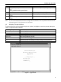
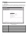
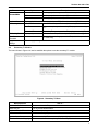
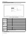
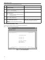
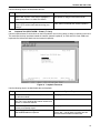
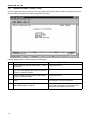
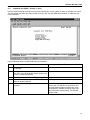
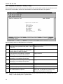
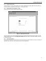
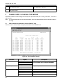
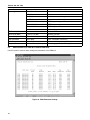
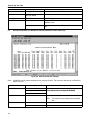
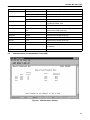
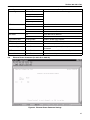
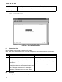
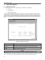
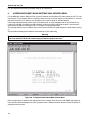
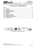
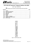
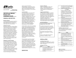
Section 360−381−C02
Telecommunications Group
Equipment Issue 2
Third Printing, August 2006
360-80 Intelligent Channel Bank Craft Terminal for T1
User’s Guide
CONTENTS
Part 1.
Part 2.
Part 3.
Part 4.
Part 5.
Part 6.
Part 7.
Part 8.
Part 9.
Part 10.
PAGE
GENERAL . . . . . . . . . . . . . . . . . . . . . . . . . . . . . . . . . . . . . . . . . . . . . . . . . . . . . . . . . . . . . . . . . . . . . . . . . . . . . 2
GETTING STARTED . . . . . . . . . . . . . . . . . . . . . . . . . . . . . . . . . . . . . . . . . . . . . . . . . . . . . . . . . . . . . . . . . . . . 2
MAIN MENU . . . . . . . . . . . . . . . . . . . . . . . . . . . . . . . . . . . . . . . . . . . . . . . . . . . . . . . . . . . . . . . . . . . . . . . . . . . 4
PRIMARY T1 MODULE . . . . . . . . . . . . . . . . . . . . . . . . . . . . . . . . . . . . . . . . . . . . . . . . . . . . . . . . . . . . . . . . . . 5
CHANNEL CARDS 1 & 2 AND HALF SIZE MODULE . . . . . . . . . . . . . . . . . . . . . . . . . . . . . . . . . . . . . . 20
USER ADMINISTRATION . . . . . . . . . . . . . . . . . . . . . . . . . . . . . . . . . . . . . . . . . . . . . . . . . . . . . . . . . . . . . . . 28
CARD INVENTORY . . . . . . . . . . . . . . . . . . . . . . . . . . . . . . . . . . . . . . . . . . . . . . . . . . . . . . . . . . . . . . . . . . . . 29
SNMP CONFIGURATION . . . . . . . . . . . . . . . . . . . . . . . . . . . . . . . . . . . . . . . . . . . . . . . . . . . . . . . . . . . . . . . 30
ADDRESSING/SUBNET MASK/MAC ADDRESS MENU . . . . . . . . . . . . . . . . . . . . . . . . . . . . . . . . . . . . 32
TECHNICAL ASSISTANCE . . . . . . . . . . . . . . . . . . . . . . . . . . . . . . . . . . . . . . . . . . . . . . . . . . . . . . . . . . . . . 33
Figure 1. Startup Screen
2006 Charles Industries Ltd.
All rights reserved. Printed in United States of America.
The availability of features and technical specifications herein subject to change without notice.
Page 1 of 33
Section 360−381−C02
1.
GENERAL
1.1
Document Purpose
This document describes how to use the Charles 360-80 Intelligent Channel Bank (ICB) Craft Terminal to monitor
and provision a local system.
Note:
This document’s issue number follows the equipment issue number of the T1 controller unit with SNMP
(T1-S).
1.2
Software Function
Use this software to manage a single ICB shelf. This interface will not allow the user to communicate with any
ICB system other than the one it is connected to. This interface uses standard VT-100 emulation software on a
PC to provision, control and monitor the 360-80 ICB.
1.3
1.4
Features
Provision all the cards in the local ICB through on-screen menus
Performance monitoring data and testing capabilities
Reference Documents
Network Management System And ICB Management System Software User’s Guide
(LT360-381-S02)
360−80 SNMP Network Node Manager (NNM) Setup Guide (LT360-381-N02)
3603−81 T1 Controller with SNMP (LT360-381-202)
3608−80 Secondary T1 Unit (LT360-880-202)
2.
GETTING STARTED
2.1
Requirements
2.2
VT100 terminal or personal computer running communications software
9600 baud rate
8-bit, no parity, 1 stop bit
RJ11 adaptor to PC terminal
Connecting to the ICB
Using a 9-pin to RJ11 adaptor (PN 03-200542-0), connect the ASCII terminal or PC serial port (COM1 or COM2)
to the jack labeled MGMT on the front of the T1 controller. See the documentation for the T1-S card for instructions.
2.3
Terminal Emulation Communication Software
When using terminal emulation communication software, such as Hyperterminal, the following settings should be
established from the pull-down menu:
2.4
File Properties Settings Terminal Keys
File Properties Settings Emulation ANSI
Starting the Craft Terminal Interface
Use the following steps to start the software and log in to the system:
2
Section 360−381−C02
Step
Action
System Response
1.
If using a PC, open your terminal emulator software.
If using an ASCII terminal, press <Enter>
Opens the startup window (see Figure 1).
2.
Press <Enter>
Opens the login window (see Figure 2).
3.
Type the default user name, piad and press
<Enter>
Password prompt is displayed.
4.
Type the default password, 1234 and press
<Enter>
Opens the main menu (see Figure 3).
Note:
The user name and password should be changed from the default as soon as possible. See the User Administration section, in this document, for instructions.
2.5
Navigating Through the Menus
To select a menu item, use the navigation keys (arrow up/down) to highlight the menu item you want; then press
<Enter> to open the menu for that item.
Use to...
Key
Arrow up ↑
Move the highlight bar up
Arrow down ↓
Move the highlight bar down
Arrow right →
Move the highlight bar to the right
Arrow left ←
Move the highlight bar to the left
<Enter>
Select the currently-highlighted menu item
<r>
Reload the screen. This usually clears any currently-selected parameters
<q>
Quit out of the current screen without saving
Figure 2. Login Screen
3
Section 360−381−C02
3.
MAIN MENU
3.1
Equipment Status
Once logged-in to the craft interface, communication is established with the T1-S allowing the status of the cards
in the shelf to be displayed. The status information is displayed on the Main Menu screen as shown in Figure 3. if
the user name used is defined as a “super user”, the system can be managed and the ICB card parameters modified from this screen.
Figure 3. Main Screen
Use to...
Menu Selection
Primary T1 Module
Set parameters for the primary T1 module
Half-size Module
Set parameters for the half-size module (channels 25−30)
Channel Card 1
Set parameters for channel card 1 (channels 1−12)
Channel Card 2
Set parameters for channel card 2 (channels 13−24)
User Administration
Add, delete, and list users
Card Inventory Data
Obtain general information about any of the cards in the system
SNMP Community Table
Set parameter for SNMP Management
Trap IP Table
Set parameters for SNMP traps
4
Section 360−381−C02
Menu Selection
Use to...
IP Address/Subnet
Mask/MAC Gateway
Address Message
Set IP address, subnet mask and gateway address
Logout
Log out of the system.
4.
T1 MODULES
4.1
Primary T1 Modules
Most settings can be found under the Primary T1 Module heading.
T1 Card Menu (Primary)
Retrieve and Set T1 Parameters
Alarm Cut Off
Loopback Test for T1
Performance Monitor
System Reset
1 KHz 0dbn0 Test Tone
Set Test Tone
Loopback Test (FXO/FXS/EM)
Loopback Test (Nx64)
Loopback Test (ISDN)
Loopback Test (DSU/OCU)
System Alarm Status
ICB Card RTC Time
Time Slot Allocation Mapping
Figure 4. Primary T1 Menu
Menu Selection
Use To...
Retrieve & Set T1 Parameters Retrieve and set the T1 parameters
Alarm Cut Off
Turn off current audible alarm
Loopback Test for T1
Run a T1 loopback test
Performance Monitor
Retrieve performance information
System Reset
Reset the system parameters either to default or to a previous setting
1 KHz 0dbm0 Test Tone
Apply an internally-generated test tone to 1 or more channels (FXO/FXS/EM)
Set Test Tone
Apply an internally-generated momentary DTMF tone to a channel
Loopback Test (FXO/FXS/EM) Loopback test menu for voice cards
Loopback Test (Nx64)
Loopback test menu for Nx64 data cards
Loopback Test (ISDN)
Loopback test menu for ISDN data cards
Loopback Test (DSU/OCU)
Loopback test menu for DSU/OCU data cards
5
Section 360−381−C02
Menu Selection
Use To...
System Alarm Status
Retrieve system alarms (display only)
ICB Card RTC Time
Set the system real-time clock
Time Slot Allocation Mapping
Allocate an available circuit to the T1 time slot
4.1.1.
Retrieve and Set T1 Parameters
Use this menu item to display the current parameters and/or change the parameters of the primary T1 card.
T1 Parameter Menu
Frame Format
Line Code
Timing Source
LBO
Auto Detect Mode
Remote Control Method
CCA Process Mode
Loopback State
T1 Working Mode
T1 Working Status
Error Second Threshold
Apply New Settings
ESF
B8ZS
Loop
0 - 110
No
Facility Data Link
Normal
Normal
Normal T1
Figure 5. T1 Parameter Options
Parameter
Frame Format
Option
Description
SF
Superframe format
ESF
Extended Superframe format
AMI
Alternate mark inversion
B8ZS
Bipolar 8 zero suppression
Loop Timing
Internal clock synchronized to incoming T1 signal
External Timing
Internal clock synchronized to external clock terminals on rear
panel
Internal Timing
Internal clock selected as master clock
LBO (Line
B ild O t)
Build-Out)
Short Haul: 0−660 ft.
Pre-equalization of signal for line conditions
Automatic
Detect Mode
No
SF/ESF must be manually selected
Yes
Auto detection of SF/ESF mode, requires loop timing
Remote Control
Method
(to remote ICB)
None
No communication to remote unit (non-Charles Industries unit)
Occupy One Channel
One channel is used for communication
Facility Data Links
Communication is over FDL (ESF mode only)
Line Code
Timing Source
6
Long Haul: 0 to 22.5 dB Receive gain control for line attenuation
Section 360−381−C02
Parameter
CGA
Process Mode
Option
Description
Normal
Carrier group alarm response characteristics per 43801
CM2
Carrier group alarm mode 2 (see T1 controller documentation)
CM3
Carrier group alarm mode 3 (see T1 controller documentation)
Loopback State
Display only. If the unit is in loopback, shows LPBK. Otherwise, shows NORMAL
T1 Working Mode
Normal T1
Normal T1 or Drop and Reinsert (if secondary T1 is installed)
Dual T1
Independent primary and secondary T1s (requires secondary
T1)
Protection T1
Secondary T1 acts as protection T1 (requires secondary T1)
T1 Working Status
Display only
Indicates active T1 (available in protection T1 mode only)
Error Second
Threshold
1-900
Threshold for switching to protection T1 (available in protection
T1 mode only)
Apply New
Settings
Select to apply changes made in this menu.
4.2
Secondary T1 Module
The menu shown in Figure 6 is used to establish the options to use the secondary T1 module.
Figure 6. Secondary T1 Menu
Menu Selection
Use To...
Retrieve & Set T1 Parameters Retrieve and set the T1 parameters
Alarm Cut Off
Turn off current audible alarm
Loopback Test for T1
Run a T1 loopback test
Performance Monitor
Retrieve secondary T1 performance information
System Alarm Status
Retrieve secondary T1 alarm status (display only)
Time slot Allocation Mapping
Allocate available circuits to primary and secondary T1 time slots.
7
Section 360−381−C02
4.2.1.
Retrieve and Set Secondary T1 Parameters
The Secondary T1 Parameter Menu, as shown in Figure 7, allows you to specify each option.
Figure 7. Secondary T1 Parameter Menu
Parameter
Frame Format
Option
Description
SF
Superframe format
ESF
Extended Superframe format
AMI
Alternate mark inversion
B8ZS
Bipolar 8 zero suppression
LBO (Line
B ild O t)
Build-Out)
Short Haul: 0−660 ft.
Pre-equalization of signal for line length
Remote Control
Method
(to remote ICB)
None
No communication to remote unit
Occupy One Channel
One channel is used for remote communication
Facility Data Links
Communication is over FDL (ESF mode only)
Loopback State
Display only. If the unit is in loopback, shows LPBK. Otherwise, shows NORMAL
Bypass Mode
Auto Bypass
T1 bypass on alarm or loss of ICB power
Forced No Bypass
No T1 bypass
No
Force no T1 bypass
Yes
Force T1 bypass
Line Code
Bypass
Apply New
Settings
4.3
Long Haul: 0 to 22.5 dB Receive gain control for line attenuation
Select to apply changes made in this menu.
Audible Alarm Cut-Off
This cancels any current audible alarm. Use the arrow keys to move the cursor to this menu item and press <Enter> to stop the alarm.
8
Section 360−381−C02
4.4
Loopback Test for T1
Use the Loopback test to troubleshoot T1 line problems. Be aware that service will be affected by these tests.
Step
Action
1.
Select the loopback state, location and type
2.
To run the loopback, select Apply New Settings.
Note:
T1 loopbacks will not function if the ICB is in alarm.
Near
Line
Figure 8. T1 Loopback Test menu
Menu Item
Loopback State
Loopback Location
Loopback Type
Option
Use to...
Test Loopback
Start loopback
Release Loopback
Stop loopback
Near
Loop local channels and send AIS to remote ICB
Far
Loop T1 at remote ICB toward near ICB
Line
Loop T1 (24 channels and overhead)
(available in ESF mode only)
Payload
(not available for Near)
Loop T1 (24 DS0 only)
Apply New Settings
Save the new parameter settings
Quit
Quit without saving
Note:
Far line loopbacks will block far end ICB remote management.
4.5
Performance Monitor
The performance monitor displays a history of the line performance. Historical data is available by quarters
(15-minute intervals, up to 96 quarters or 24 hours) and days (up to 30 days).
9
Section 360−381−C02
Figure 9. Performance Monitor screen with 15-Minute Performance Data
4.5.1.
15-Minute PM Data
Use the following steps to look at 15 minutes of PM data:
Step
Action
System Response
1.
Select 15-min. and press <Enter>.
(Figure 9 shows the third 15-minute segment)
Asks you what 15 minute period you want to look at. Choices are
0 to 96, with 0 specifying the current 15 minutes, and 96 specifying 96 quarters (24 hours) prior. The actual date on which the data
was gathered is also displayed
2.
Select a 15-minute interval and
press <Enter>
Retrieved data (errored seconds, severe errored seconds and unavailable second count) is displayed at the bottom of the screen
3.
Press <Enter> to look at more data
(another 15-minute period or update current status), or <q> to quit.
4.5.2.
One Day PM Data
Use the following steps to look at one day of PM data:
Step
Action
System Response
1.
Select 1-day and press <Enter>
Asks you what day you want to look at. Choices are 0 to 30, with
0 specifying the current day, and 30 specifying 30 days prior
2.
Select a day interval and press
<Enter>
Retrieved data (errored seconds, severe errored seconds and unavailable second count) is displayed at the bottom of the screen.
The actual date on which the data was gathered is also displayed.
3.
Press <Enter> to look at more data
(review current or previous day), or
<q> to quit.
10
Section 360−381−C02
4.5.3.
Reset PM Data
Use to clear stored data. Select Now to reset data at the current time, or select Today to reset data from the start
of the current day.
4.6
System Reset (Primary T1 Only)
4.6.1.
Reset to Stored Values
Performs a system reset using the T1 and card configuration at the time of the reset.
4.6.2.
Reset to Factory Default Values
Perform a system reset using the factory default T1 and card parameters. A system reset will clear all configuration information from the Community table and the Trap IP table. Refer to the documentation for each individual
unit for default values.
4.7
1 KHz 0dbm0 Test Tone (Primary T1 Only)
Applies a 1 KHz 0dbm0 test tone for channel setup procedures.
Note:
This test is valid for voice cards only.
Figure 10. 1 KHz 0db Test Tone Menu
11
Section 360−381−C02
Use the following steps to enable/disable the tone test.
Step
Action
System Response
1.
Select which card you want to test (Card 1, Card 2
or half-size module)
2.
Select the channel number you want to test. Use
Flags the channel
the <Tab> key to highlight the channel number and
<Enter> to select the channel
3.
Select the operation setting. Enable starts the test, Displays your choice
and Disable stops it
Note:
4.
5.
4.8
Disable will stop any enabled test tones on
the selected channel.
Select the direction of the test (XMT or RCV)
Note:
Displays your choice
Displays your choice
XMT is toward the T1.
Select Apply New Settings to save your choices
and enable/disable the test tone
Press <q> to exit the menu without saving your
changes
If you have chosen to enable the tone test, this will
start the test. You will have to go back into this
menu and select Disable to end the test.
Set Test Tone (Primary T1 Only)
Use this screen to select a channel to be tested with a momentary tone.
Note:
This test is valid for voice cards only.
Tone Parameters Menu
Card Type = FXO
Card Type = FXS
Card Type = Unplugged
Select Channel
Apply New Setting
Figure 11. Tone Parameters Menu
12
Section 360−381−C02
Use the following steps to enable/disable the test.
Step
Action
System Response
1.
Select the channel number(s) on any card you
want to test. Use the <Tab> key to highlight the
channel and <Enter> to select the channel
Flags the channel you have selected. Only channels capable of using this test will be shown
2.
Select Apply New Settings to enable the test.
Press <q> to exit the menu without saving your
changes
The test tone is applied momentarily to the selected channel to validate the channel operation.
4.9
Loopback Test (FXO/FXS/EM − Primary T1 Only)
Use the Loopback tests to check where on the line problems are occurring when an alarm is reported on the card.
This test loops the drop input back toward the network (network loopback), for FXS and FXO cards. E&M card
loopbacks are bidirectional (both local and network loopbacks).
Figure 12. Loopback Test menu
Use the following steps to enable/disable the card loopback.
Step
Action
System Response
1.
Select which card you want to test (Card 1, Card 2
or half size module)
Displays your choice
2.
Select the channel number you want to test. Use
Flags the channel
the <Tab> key to highlight the channel number and
<Enter> to select the channel
3.
Select to enable or disable the test. Enable starts
the test, and Disable stops it
Displays your choice
4.
Select Apply New Settings to save your choices.
and enable/disable the loopback
If you have chosen to enable the loopback, this will
start the test. You will have to go back into this
menu and select Disable to end the test.
13
Section 360−381−C02
4.10
Loopback Test (Nx64 − Primary T1 Only)
Use the Loopback test to check where on the line problems are occurring when an alarm is reported on the card.
See the Nx64 documentation for additional loopback information.
Use the following steps to enable/disable the card loopback.
Step
Action
System Response
1.
Select which card you want to test (Card 1, Card 2
or half size)
2.
Select the channel number you want to test. Use
Flags the channel
the <Tab> key to highlight the channel number and
<Enter> to select the channel
3.
Select to enable or disable the test. Enable starts
the test, and Disable stops it
Displays your choice
4.
Select the loopback mode (local, network or remote)
Displays your choice. V.54 must be enabled on
64xN settings to use remote loopback
5.
Select Apply New Settings to save your choices.
and enable/disable the loopback
If you have chosen to enable the loopback, this will
start the test. You will have to go back into this
menu and select Disable to end the test.
14
Displays your choice
Section 360−381−C02
4.11
Loopback Test (ISDN − Primary T1 Only)
Use the Loopback test to check where on the line problems are occurring when an alarm is reported on the card.
This test applies only when the channel mode is set to LUNT. See the ISDN documentation for additional loopback information.
Use the following steps to enable/disable the card loopback.
Step
Action
System Response
1.
Select which card you want to test (Card 1, Card 2
or half size)
Displays your choice
2.
Select the channel number you want to test. Use
Flags the channel
the <Tab> key to highlight the channel number and
<Enter> to select the channel
3.
Select the test pattern (NO or YES)
Displays your choice (for future use)
4.
Select the loopback type (local, LULT or NT1) or
select to release loopback
Displays your choice
5.
Select Apply New Settings to enable/disable the
loopback
If you have chosen to enable the loopback, this will
start the test. You will have to go back into this
menu and select Disable to end the test. Verify
that loopback is enabled by looking at the front
panel of the card you are testing. The LB LED
should be ON.
15
Section 360−381−C02
4.12
Loopback Test (DSU/OCU − Primary T1 Only)
Use the Loopback test to check where on the line problems are occurring when an alarm is reported on the card.
See the DSU documentation and the OCU documentation for additional information on loopbacks.
Loopback Test OCU/DSU Menu
Select Card
Select Channel
OCU Loopback
CSU Loopback
DSU Loopback
Local LPBK
Direction
2047 Pattern
Apply New Settings
Enable
Near
Disable
Use the following steps to enable/disable the card loopback.
Step
Action
System Response
1.
Select which card you want to test (Card 1, Card 2
or half size)
Displays your choice
2.
Select the channel number to test.
Use the <Tab> key to highlight the channel number and <Enter> to select the channel
Flags the channel
3.
OCU Loopback. Select latching or unlatching
(unlatching is not available at the 64K rate)
Displays selection
4.
CSU Loopback. Select latching or unlatching
(unlatching is not available at the 64K rate)
Displays selection
5.
DSU Loopback. Select latching or unlatching
(unlatching is not available at the 64K rate)
Displays selection
6.
Local LPBK. Select enable or disable
Displays selection
7.
Direction. Select near or far
Displays selection
8.
2047 Pattern. Select enable or disable
Displays selection
9.
Select Apply New Settings to save your choices
and enable/disable the loopback
If you have chosen to enable the loopback, this will
start the test. You will have to go back into this
menu and select Disable to end the test.
Note:
16
DSU/OCU, near and far end loopback generators, do not function when the ICB is equipped with a secondary T1 card operating in the T1 protect mode.
Section 360−381−C02
4.13
System Alarm Status
Use this selection to retrieve current alarms in the system. Highlight System Alarm Status and press <Enter> to
retrieve the alarms. To update the status, press “r” to reload the screen.
4.14
ICB Card RTC Time (Primary T1 Only)
Use this selection to set the real-time clock on the ICB.
Figure 13. Real-Time Clock menu
To set the real-time clock, use the up/down arrows to move between the selections and press <Enter> to make
changes. When you are done, select Apply New Settings and press <Enter> to save your changes. Press <q>
to quit without saving.
4.15
Time Slot Allocation
Use the time slot allocation menu to change the time slot location of a channel within the primary or secondary T1
signal time slots. This menu is also used for drop and reinsert applications.
17
Section 360−381−C02
Figure 14. Setting the Time Slot Allocation
4.15.1. Time Slot Mapping
Use the following steps to change the time slot mapping. Steps 1 through 3 unallocate channels from time slots.
Steps 4 through 7 allocate channels to time slots. Time slots/channels must be unallocated before they can be
allocated.
Step
Action
System Response
1.
Display the channel to edit by pressing the <tab>
key
Channel is displayed.
2.
Press <Enter>
Channel is selected.
3.
When asked, “Clear time slot?” Use the arrow
keys to select yes, and then press <Enter> to unallocate the channel from its allocated time slot.
Channel is unallocated.
4.
Repeat steps 1 and 2 for all channels to be
unallocated
5.
Press <tab> to highlight an unallocated channel
and then press <Enter>
Prompted to map the selected channel to a primary or secondary (if the equipment exists) T1 time
slot.
6.
Select primary or secondary and then press
<Enter>
Map direction is selected.
7.
Press <tab> to select the time slot to map to the
selected channel and then press <Enter>
The time slot is allocated appropriately for the card
type and card provisioning.
8.
Press <t> to select the retrieve time slot status
screen
This screen displays a green square under all time
slots that have been allocated to a channel.
18
Section 360−381−C02
Step
Action
9.
Repeat steps 4 and 5 to map any other channels
that are not allocated
10.
Press <b> to enter the time slot mode menu. This
selection is only available if the secondary T1 card
is installed.
Note:
System Response
Channels are mapped.
Retrieve Time Slot Status is only visible if the property emulation mode is set to ANSI. This status indicates the time slots that have been allocated.
4.15.2. Time Slot Allocation Mode (Only with a Secondary T1 Unit Installed)
Use this menu to choose whether unallocated slots on either T1 unit will be sent broadcast data or idle code. Selecting Idle fills the slot with idle code; Broadcast fills the slot with the data sent by the other T1.
Figure 15. Setting the Time Slot Mode
Note:
This menu is only available if a secondary T1 unit is in the normal (Drop/Reinsert) mode. Slots that are
not dropped must be set to broadcast on both the primary and secondary T1s to pass data from one T1
to the other T1. Changing the time slot provisioning does not affect the operation of the ICB if the mode is
not set to normal.
Use the following steps to change the time slot mode:
Step
Action
System Response
1.
Select Time Slot Mode and press <Enter>
Refreshes the screen to show the time slot modes
2.
Press <tab> to display the time slot you want to
edit
Displays the time slot.
3.
Press <Enter> to select the time slot
Asks you the direction you want to modify.
19
Section 360−381−C02
4.
Use the arrow keys to highlight the desired direction and press <Enter>
Asks you which mode you want to set—
Bdct=broadcast or Idle=idle
5.
Use the arrow keys to highlight the desired mode
and press <Enter>
Applies the mode to the selected time slot.
5.
CHANNEL CARDS 1 & 2 AND HALF SIZE MODULE
Parameters available on these dialog boxes will depend upon what cards you are using in the Card 1, Card 2 and
half size slots.
Note:
For complete descriptions of the card parameters, refer to the documentation for the individual cards you
are using.
5.1
FXO Parameters (for 3658-80 12 Channel FXO/DPT Unit)
Use this screen to retrieve and/or change the parameters of the FXO/DPT unit.
Figure 16. FXO Parameter Settings
Parameter
Channel Selection
Option
1−12 (if in Card 1 slot)
13−24 (if in Card 2 slot)
Description
Select the channel the parameters will be applied
to Each channel can be configured individually
to.
25−30 (if in half size slot)
Channel Impedance
600 ohms
Loop matching impedance
900 ohms
Operating Mode
20
FXO/GS
FXO—ground start
FXO/LS
FXO—loop start
DPT/NORMAL
DPT—Normal
DPT/WINK
DPT—Automatic wink
Section 360−381−C02
Parameter
Option
TTLP Level (dBm)
−10.0 to +6.0 dBm
Transmit TLP level
RTLP Level (dBm)
−10.0 to +6.0 dBm
Receive TLP level
Forced Busy
YES or NO
Select YES to force busy
CGA Immediate
Idle or Busy
CGA—immediate conditioning
CGA Delayed
Idle or Busy
CGA—conditioning after alarm delay
5.2
Description
FXS Parameters (for 3657-80 12 Channel FXS/DPO Unit)
Use this screen to retrieve and/or change the parameters of the FXS/DPO unit.
Figure 17. FXS Parameter Settings
Parameter
Channel Selection
Option
1−12 (if in Card 1 slot)
13−24 (if in Card 2 slot)
Description
Select the channel the parameters will be applied
to Each channel can be configured individually
to.
25−30 (if in half size slot)
Channel Impedance
600 ohms
Loop matching impedance
900 ohms
21
Section 360−381−C02
Parameter
Operating Mode
Option
Description
FXS/GS
Ground start
FXS/LS
Loop start
PLARD/D3
Private line automatic ringdown
PLARD/D4
Private line automatic ringdown
MEGACOM/GS/immediate
AT&T Megacom—ground start
MEGACOM/GS/wink
AT&T Megacom—ground start
MEGACOM/LS
AT&T Megacom—loop start
DPO
Dial pulse originate
TTLP Level (dBm)
−10.0 to +6.0 dBm
Transmit TLP level
RTLP Level (dBm)
−15.0 to +1.0 dBm
Receive TLP level
Forced Busy
YES or NO
Select YES to force busy.
CGA Immediate
Idle or Busy
CGA—immediate conditioning
CGA Delayed
Idle or Busy
CGA—conditioning after alarm delay
Ring Mode
Burst, continuous, interrupted
Select ringing mode (PLARD only)
5.3
E&M Parameters (for 3652-80 12 Channel E&M Unit)
Use this screen to retrieve and/or change the parameters of the E&M unit.
Figure 18. E&M Parameter Settings
22
Section 360−381−C02
Parameter
Option
Channel Selection
Description
1−12 (if in Card 1 slot)
13−24 (if in Card 2 slot)
Select the channel the parameters will be applied
to Each channel can be configured individually
to.
25−30 (if in half size slot)
Card Type
2W/4W and 600/900
Indicates 2W/4W jumper settings and 600/900
jumper settings
Forced Busy
YES or NO
Select YES to force busy
Channel Type
Type 1−5
Select E&M signaling lead type
Transmission Only
No signaling leads used
TTLP Level (dBm)
−19.0 to +13.0 dBm
Transmit TLP level
RTLP Level (dBm)
−19.0 to +13.0 dBm
Receive TLP level
CGA Immediate
Idle or Busy
CGA immediate conditioning
CGA Delayed
Idle or Busy
CGA conditioning after alarm delay
5.4
OCU-DP Parameters (for 3632-80 12-Channel Office Channel Unit – Data Port)
Alternating
CMI Code
BCH Err.
Correction
Zero Code
Suppression
Speed Sub.
Channel
Latching
LPBK
CSU/
DSU
Disable
Disable
Disable
Disable
Disable
Disable
Disable
Disable
Disable
Disable
Disable
Disable
Disable
Disable
Disable
Disable
Disable
Disable
Disable
Disable
Disable
Disable
Disable
Disable
Disable
Disable
Disable
Disable
Disable
Disable
Disable
Disable
Disable
Disable
Disable
Disable
64K
64K
64K
64K
64K
64K
64K
64K
64K
64K
64K
64K
Disable
Disable
Disable
Disable
Disable
Disable
Disable
Disable
Disable
Disable
Disable
Disable
DSU
DSU
DSU
DSU
DSU
DSU
DSU
DSU
DSU
DSU
DSU
DSU
Ch13
Ch14
Ch15
Ch16
Ch17
Ch18
Ch19
Ch20
Ch21
Ch22
Ch23
Ch24
Figure 19. OCU-DP Parameter Settings
Parameter
Channel Selection
Option
1−12 (if in Card 1 slot)
13−24 (if in Card 2 slot)
Description
Select the channel the parameters will be applied to.
Each channel can be configured individually
25−30 (if in half size slot)
Alternate CMI Code
Enable/Disable
Available for SW 56K data rate
BCH Error Correction
Enable/Disable
Enables error correction. Available for 19.2K, 56K and
64K data rates
23
Section 360−381−C02
Parameter
Option
Description
Zero Code Suppression Enable/Disable
Select to transmit a code if an all-zero byte is detected
Speed Sub. Channel
2.4K, 4.8K, 9.6K, 19.2K,
56K, 64K, SW56
Select transmission data rate for any or all channel slots
Latching LPBK
Enable/Disable
Available for all data rates
CSU/DSU
CSU
Converts DSU loopback codes from network to CSU
loopback codes
DSU
Normal operation. Allows DSU loopback codes to be
sent.
5.5
DSU-DP Parameters (for 3633-80 12 Channel Data Service Unit—Data Port)
Figure 20. DSU-DP Parameter Settings
Note:
Availability of some options depends on the data rate chosen. The maximum data rate for an RS-232 interface is 19.2K.
Parameter
Channel Selection
Option
1−12 (if in Card 1 slot)
13−24 (if in Card 2 slot)
Description
Select the channel the parameters will be applied to.
Each channel can be configured individually
25−30 (if in half size slot)
ASYNC/SYNC Mode
ASYNC or SYNC
Synchronous or asynchronous data transmission
Note:
CTS Control
24
This mode must be selected to set the data
rate.
Yes
Force clear-to-send
No
Normal
Section 360−381−C02
Parameter
Option
DSR Control
Description
Yes
Force data set ready
No
Normal
Yes
Force data carrier detect
No
Normal
Interface Mode
3RS+V/V.35/RS232
Select the interface mode. 3RS+V selects the following: RS449, RS530, V.36
Latching Loopback
Enable/Disable
Enable/disable detection of latching loopback codes
Data Rate
2.4K, 4.8K, 9.6K, 19.2K, 56K,
64K
Transmission data rate. 56K and 64K available in
synchronous (SYN) mode only
Stop Bit Shortened
12.5% or 25%
Asynchronous (ASYN) mode shortened stop bits
Parity Bit
Yes/No
Asynchronous (ASYN) mode only
7/8 Bits Mode
7 or 8
Asynchronous (ASYN) mode only
Stop Bit
1 or 2
Asynchronous (ASYN) mode only
Error Correction
Enable/Disable
BCH error correction
DCD Control
Zero Code Suppression Enable/Disable
Converts zero byte to control code (18 Hex) toward
the network
RTS Force On
Force request to send ON.
5.6
Yes/No
ISDN Parameters (for 3638-80 Quad Circuit ISDN)
Ch13
Ch14
Ch15
Ch16
Mode
Sealing
Current
nB+nD
Composite
CLk Source
LULT
LULT
LULT
LULT
On
On
On
On
2B+D
2B+D
2B+D
2B+D
None
None
None
None
Figure 21. ISDN Parameter Settings
25
Section 360−381−C02
Parameter
Channel Selection
Option
Description
1−4 (if in Card 1 slot)
Select the channel the parameters will be applied
to Each channel can be configured individually
to.
13−16 (if in Card 2 slot)
25−26 (if in half size slot)
Mode
LULT
RT mode
LUNT
COT mode
Sealing Current
ON/OFF
Status (LULT only)
nB + nD
D
Overhead channel only
1B + D
One data/voice channel plus overhead
2B + D
Two data/voice channels plus overhead
None
Select composite clock output source. Applies
only to LUNT mode.
mode
Composite Clock Source
1−4 (If in card 1 slot)
13−16 (if in card 2 slot)
25, 26 (if in half size slot)
5.7
56/64xN Parameters (for 3634-80 6-Circuit 56/64xN Data Service Unit—Data Port)
Figure 22. 56/64xN DSU-DP Parameter Settings
Parameter
Channel Selection
Option
1−6 (if in Card 1 slot)
13−18 (if in Card 2 slot)
Description
Select the channel the parameters will be applied to. Each
channel can be configured individually
25−27 (if in half size slot)
Nx56/64K
1 thru 24
Depends on bandwidth desired and time slots allocated
Base Setting
56K or 64K
Base data rate
26
Section 360−381−C02
Parameter
Channel Type
Option
RS530
Description
Select the serial interface connection type
V.35
V.36 (RS−449/422)
RS232
HIZ (factory test mode)
CTS Value
Yes
Force clear-to-send on
No
Normal
Yes
Force data set ready on
No
Normal
Yes
Force data carrier detect on
No
Normal
V.54 LPBK Enable
Enable/Disable
Enable or disable V.54 loopback
DTE LL Loopback
Enable/Disable
Enable or disable DTE local loopback
Idle Mode
11111110 or 11111111
Select idle mode pattern
DSR Value
DCD Value
Zero Code Suppression Enable/Disable
Force control code (18 Hex) if zero byte detected toward
the network
PRTS
Enable/Disable
Force request to send ON and continually send data
External Clock
Enable/Disable
Select an external input as a clock source.
5.8
Ethernet Router Parameters (for 3641-80 or 3648−80)
Figure 23. Ethernet Router Parameter Settings
27
Section 360−381−C02
Parameter
Option
Description
Nx56/64K
1 thru 24
Depends on bandwidth desired and time slots allocated
Base Setting
56K or 64K
Base data rate
6.
USER ADMINISTRATION
Use the User Administration menu to add and delete users.
Figure 24. User Administration Menu
6.1
Create a New User
Use the following steps to create a new user on the system.
Note:
User names and passwords must not contain blank spaces, and should be limited to eight characters.
Step
Action
System Response
1.
Select Create New User and press <Enter>
Asks for the new user’s name
2.
Type the new user’s name and press <Enter>
Asks for the new user’s password
3.
Type a password for the new user and press <Enter>
Asks to verify the new user’s password
4.
Type the new user’s password a second time and
press <Enter>
Asks you to select the new user’s security level
5.
Select the new user’s security level
Guest= Allows access to status and performance data
User= Full system access except for user maintenance
Super user= Full system access and press <Enter>
Adds the new user to the system.
6.2
Delete User
Use the following steps to remove a user from the system:
28
Section 360−381−C02
Step
Action
System Response
1.
Select Delete Existing User and press <Enter>
Ask for the user’s name
2.
Type in the user’s name and press <Enter>
Deletes the user.
6.3
Editing User Information
There is no provision for editing user information directly. If you want to change a user’s password or access level, you must delete the user and then add the user to the system again with the changes.
6.4
List Users
Use the following steps to list the current users in the system:
Step
1.
7.
Action
System Response
Select List User Information and press <Enter>
Retrieves and displays a list of the current users.
CARD INVENTORY
Retrieve information about any of the cards in the system.
2.1
FPGA Version 5
Figure 25. Card Inventory Data After Primary T1 Selected
Use the following steps to retrieve card information.
Step
Action
System Response
1.
Select Card Inventory and press <Enter>
Opens the Card Inventory menu
2.
Select the card you want to see data for and
press <Enter>
Retrieves the card firmware and FPGA version inventory
data (see Figure 25)
3.
When you are done, press <q> to quit.
29
Section 360−381−C02
8.
SNMP CONFIGURATION
8.1
SNMP Community Table
For SNMP management, the T1-S is addressed using a combination of the following:
IP Address
Community Name
Address ID Switch Setting
A “Reset to Factory Settings” will clear the table configuration. Only locally managed shelves need the SNMP
community table set. A locally managed shelf is any ICB that is connected to a manager via an Ethernet LAN regardless of where the shelf is physically located. A remotely managed shelf is an ICB that is managed over a T1
through a locally managed shelf. The SNMP Network Node Manager documentation provides additional information.
Figure 26. SNMP Community Table
Parameter
Description
Community
Enter the name to be used to refer to this equipment
Privilege
Use Read for monitoring and Read/Write for monitoring and provisioning
IP Address
Enter the IP address of the SNMP manager
Submask
Enter the appropriate subnet mask.
Warning
Applying changes to this table will initiate a warm start and momentarily disrupt T1 service.
Note:
30
New settings must be applied after changes are made to activate the changes to this table.
Section 360−381−C02
8.2
Trap IP Table
Traps must be enabled in this table and through the MIB (instance iadTrapSetProxy under iadTrapMgt) to be generated by the ICB.
Traps must be enabled using the SNMP manager.
Traps will only be generated based on local system conditions. A local system is any system that is directly connected via an Ethernet LAN to the management network. A “Reset to Factory Settings” will clear the table configuration. The SNMP Network Node Manager documentation provides additional information.
Figure 27. Trap IP Table
Parameter
Description
Community
Enter the name to be used to refer to this equipment
IP Address
Enter the IP address of the Trap recipient
Status
Traps must be Enabled to be generated.
Warning
Applying changes to this table will initiate a warm start and momentarily disrupt T1 service.
Note:
Note: The following eight traps are supported by this equipment:
ACTLPBKLF alarm trap (T1 Line far−end loopback)
ACTLBKP alarm trap (T1 payload far−end loopback)
AIS alarm trap
LOF alarm trap
LOS alarm trap
YEL alarm trap
warm start
authentication trap
31
Section 360−381−C02
Far−End loopback traps will be generated at the far−end equipment.
9.
ADDRESSING/SUBNET MASK/GATEWAY//MAC ADDRESS MENU
For the NMS/GUI software (Ethernet GUI) only the IP address and the address ID switch setting of the T1-S card
are required. (The IP address and the community name can only be viewed using the Craft interface.) If a remote
ICB does not require an IP address, use IP address 0.0.0.0 with a subnet of 255.255.255.255.
Only locally managed shelves need to have an IP address set. A locally managed shelf is any ICB that is connected to a manager via an Ethernet LAN regardless of where the shelf is physically located. A remotely-managed shelf is an ICB that is managed over a T1 through a locally managed shelf.
The gateway address is the IP address of the router on the LAN that is located between the shelf and the manager.
See the Network Management Software documentation for GUI addressing.
Warning
All remotely managed systems must have a unique address ID switch setting that is different from
the local system’s address ID switch setting and must be greater than zero.
Figure 28. IP Address/Subnet Mask/MAC Address Menu
Enter the appropriate IP address and subnet mask for the network connected to the ICB. SNMP and Graphical
User Interface Network Management is NOT possible over the Ethernet interface unless a unique IP address is
assigned to the local shelf.
32
Section 360−381−C02
WARNING
Applying changes to this table will initiate a warm start and momentarily disrupt T1 service.
The MAC address is unique for each ICB and cannot be changed.
9.1
SNMP Management using Charles MIB
Provided on the CD included with the T1 Controller with SNMP (T1-S) is the Charles MIB for management of the
360−80 system. Only a system with a T1-S card as the controller can be managed using an SNMP manager.
Note:
See the Network Node Manager documentation for more information.
10.
TECHNICAL ASSISTANCE
If technical assistance is required, contact Charles Industries’ Technical Services Center at:
847-806-8500
847-806-8556 (FAX)
800-607-8500
[email protected] (e-mail)
33