1
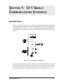
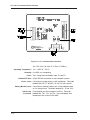
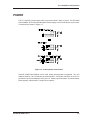
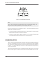
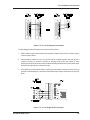
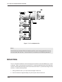
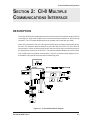
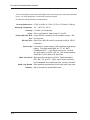
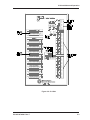
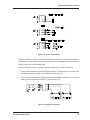
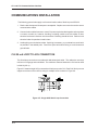
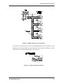
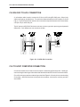
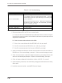
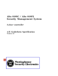
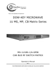
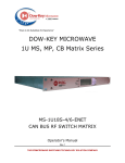
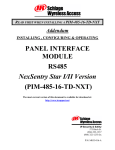
CI-1 and CI-8 Communications Interface 5452 Betsy Ross Drive Santa Clara, CA 95054-1184 (408) 727-5170 FAX (408) 727-6707 P/N 66104700001 Rev. F r y h H © 1997 Westinghouse Security Electronics. All rights reserved. DigiReader, NexKey, QuadraKey, DuraKey, NexSentry and NexStar are trademarks of Westinghouse Security Electronics. Printed in the United States of America. ii LIMITED WARRANTY WSE warrants to the original user the Equipment manufactured by WSE as described herein (the Equipment) to be free from defects in material and workmanship for a period of one year from the date of purchase by such user or fifteen (15) months from the date of shipment from the factory, whichever is sooner, provided: I WSE has been notified within such period by return of any alleged defective equipment, free and clear of any liens and encumbrances to WSE or its authorized Dealer at the address specified, transportation prepaid; and II the Equipment has not been abused, misused or improperly maintained and/or repaired during such period; and III such defect has not been caused by ordinary wear and tear; and IV such defect is not a result of voltage surges/brownouts, lightning, water damage/flooding, fire, explosion, earthquakes, tornadoes, acts of aggression/war or similar phenomena; and V accessories used as integral to WSE Systems have been approved by WSE (e.g., coaxial cables, batteries, etc.); and VI the Equipment has been installed, the installation supervised or installation tested by an authorized WSE Dealer. WSEs Analog Proximity Command Keys are warranted for 5 years. WSE shall at its option, either repair or replace, free of charge, the Equipment found, upon WSEs inspection to be so defective, or if agreed upon, refund the purchase price, less a reasonable allowance for depreciation, in exchange for the Equipment. WSE MAKES NO OTHER WARRANTY, AND ALL IMPLIED WARRANTIES INCLUDING ANY WARRANTY OF MERCHANTABILITY OR FITNESS FOR A PARTICULAR PURPOSE ARE LIMITED TO THE DURATION OF THE EXPRESSED WARRANTY PERIOD AS SET FORTH ABOVE. WSE MAXIMUM LIABILITY HEREUNDER IS LIMITED TO THE PURCHASE PRICE OF THE EQUIPMENT. IN NO EVENT SHALL WSE BE LIABLE FOR ANY CONSEQUENTIAL, INDIRECT, INCIDENTAL OR SPECIAL DAMAGES OF ANY NATURE ARISING FROM THE SALE OR USE OF THE EQUIPMENT. Some states do not allow limitations on incidental or consequential damages or how long an implied warranty lasts, so the above limitations may not apply. This warranty gives specific legal rights; however, other rights which vary from state to state, may pertain. The information provided in this manual is believed to be accurate and reliable. However, Westinghouse Security Electronics (WSE) assumes no responsibility for any errors that may appear. Possession of this manual does not imply the granting of licenses to make or sell equipment or software constructed according to descriptions provided. iii FEDERAL COMMUNICATIONS COMMISSION RADIO FREQUENCY INTERFERENCE STATEMENT This equipment has been tested and found to comply with the limits for a Class A computing device in accordance with the specifications in Subpart J of Part 15 of the FCC Rules. These limits are designed to provide reasonable protection against harmful interference when the equipment is operated in a commercial environment. This equipment generates, uses, and can radiate radio frequency energy and, if not installed and used in accordance with the installation manual, may cause harmful interference to radio communications. Operation of this equipment in a residential area is likely to cause harmful interference, in which case the user will be required to correct the interference at his own expense. Only peripherals, included shielded cables, certified to comply with the Class A limits may be attached to this computer. Changes or modifications not expressly approved by WSE could void the users authority to operate the equipment. Some components may comply with Class B rules, and if so will be so marked. If necessary, consult the dealer or an experienced radio/television technician for additional suggestions. The user may find helpful the following booklet prepared by the Federal Communications Commission:How to Identify and Resolve Radio/TV Interference Problems. The booklet is available from the US Government Printing Office (stock number: 004-000-00345-4). iv Contents Limited Warranty ....................................................................................................... iii Federal Communications Commission RFI Statement ............................................. iv Section 1: CI-1 Single Communications Interface Description ............................................................................................................. 1-1 Power ..................................................................................................................... 1-3 Communication ...................................................................................................... 1-4 Mounting ................................................................................................................ 1-6 Troubleshooting...................................................................................................... 1-7 Poor or No Communication ............................................................................ 1-7 Loopback Test ................................................................................................ 1-8 Power Supply and Battery .............................................................................. 1-8 Section 2: CI-8 Multiple Communications Interface Description ............................................................................................................. 2-1 Mounting ................................................................................................................ 2-4 Power ..................................................................................................................... 2-4 Communications Installation .................................................................................. 2-6 CI-8 20 mA Loop to ACU Connection ............................................................ 2-6 CI-8 RS-232C to ACU Connection ................................................................. 2-8 CI-8 to Host Computer Connection ................................................................ 2-8 Troubleshooting...................................................................................................... 2-9 v SECTION 1: CI-1 SINGLE COMMUNICATIONS INTERFACE DESCRIPTION The CI-1 can be used to connect up to four ACUs to a single host computer and to extend the distance between an ACU and host computer to 2000 ft (610 m) A block diagram of a typical CI1 installation is shown in Figure 1-1. The CI-1 is designed to operate only with WSE access control equipment, and only as described herein. For other applications, contact WSE Customer Support. Figure 1-1: CI-1 Installation Block Diagram ACUs connected to a host through the CI-1 may be any combination of WSE NexSentry, Alto 818 and SE 808 devices using 20 mA loop communication. The CI-1 to host connection uses RS232 communication over a maximum distance of 25 feet (7.6 meters). The CI-1 to host communication may be at a baud rate of up to 9600. Figure 1-2 shows the front of a CI-1. P/N 66104700001 Rev. F 1-1 CI-1 and CI-8 Communications Interface Figure 1-2: CI-1 Communications Interface Housing Dimensions Operating Temperature Humidity Fuses RS-232 DTE Port 32° 120°F (0° 50°C) 0 to 95% non-condensing Two .5-amp fuses for battery input, F1 and F2. 25-pin RS-232 connection to host computer system. Power Input Connection to power supply or AC transformer. Terminals labeled AUX AC, CT and AC; 18 VAC, 80 mA nominal. Battery Backup Input Connection to backup battery; two 12-volt batteries rated at 2 to 6 amp-hours. Terminals labeled12V-, C and 12V+. 20mA Loop Connector 1-2 4in X 5in X 2in (10.16cm X 12.70cm X 5.08cm) Four-terminal port for connection to ACUs. Terminals labeled RX+, RX-, TX+ and TX-. Use unshielded, dual, twisted pair wire, minimum 24 AWG. CI-1 Installation and Operation POWER The CI-1 requires a power supply which can provide 18VAC, 80mA, nominal. The SE 3018S Power Module, SE 3718SU Uninterruptible Power Supply or an AC transformer may be used. Connections are shown in Figure 1-3. Figure 1-3: Primary Power Connections If the SE 3018S Power Module is to be used, battery backup power is suggested. Two 12V batteries rated for 2 to 6 amp-hours are recommended. A three-pin connector on the CI-1 is provided to connect the batteries; see Figure 1-4. Battery inputs are fused. Check the battery fuses regularly; replace with a ½-amp fuse as required. P/N 66104700001 Rev. F 1-3 CI-1 and CI-8 Communications Interface Figure 1-4: Backup Battery Connection NOTE: The CI-1 does not charge the two 12VDC batteries; use an external battery charger. The charge level must be checked periodically to assure proper power levels. Follow the below procedure to connect batteries to the CI-1. Connecting the batteries incorrectly will blow one or both fuses on the CI-1. 1. Connect the first battery's negative terminal to the -12 V terminal of the CI-1, and connect the battery's positive terminal to the common (C) terminal. 2. Connect the second battery's negative terminal to the CI-1 common (C) terminal, and connect the battery's positive terminal to the +12 V terminal of the CI-1. COMMUNICATION The CI-1 connects to the ACUs via the 20 mA terminals. Four-wire, dual twisted-pair, 24-gauge (minimum), unshielded wire is required. Four wires in a single twisted configuration may not be used. The maximum cable length is 2000 ft, to a maximum of four ACUs when no RF interference is present. The actual cable length and number of ACUs supported will be impacted by environmental conditions The ACU cable supplied with the host or a standard null-modem cable may be used to connect the CI-1 and host. Figure 1-5 shows the minimum wire connections between the CI-1 and host. 1-4 CI-1 Installation and Operation Figure 1-5: CI-1 to Host System Connection The following general rules apply to all communication cables: 1. Plastic cable clamps and tie-wraps are acceptable. Staples must never be used to secure communication cables. 2. Communication cables from the CI-1 ports may be bundled together and may share a common conduit run; however, bundling or sharing conduit runs with cables of other electrical or electronic devices must be avoided. Bundling should be loose, and conduit sizes should be as required by the electrical codes. 3. Avoid splicing communication cables. If splicing is unavoidable, maintain as much 'twist' as possible in the twisted pairs. Protect the splice with shrink tubing to avoid shorts and ground faults. Figure 1-6: CI-1 to Single ACU Connection P/N 66104700001 Rev. F 1-5 CI-1 and CI-8 Communications Interface Figure 1-7: CI-1 to Multiple ACUs NOTE: If the 20mA loop includes SE 818 or NexSentry ACUs, each must be powered on for any communication with the host. Communication is not lost when an SE 808 is powered off. MOUNTING The CI-1 should be installed in an electrical equipment cabinet such as the NEMA Type 1 panel enclosure. Often, it is convenient to mount the CI-1 in the same cabinet as the ACUs and power module. Double-sided foam tape on the back of the case of the CI-1 permits mounting on most surfaces. A cabinet should provide: 1. Wiring clearance of 6 in (15 cm) around the edges of each unit. 2. Service clearance of approximately 8 in (20 cm) at the front of each unit. 1-6 CI-1 Installation and Operation 3. Adequate ventilation to remain within the operating temperature and humidity specifications. Careful site selection is essential prior to installation. Ensure that your site meets all the following requirements: 1. Within 2000 ft of each ACU (distance measured in cable length). 2. Within 25 ft of the RS-232 host interface. 3. A minimum of 6 ft (2 m) from high voltage or high power equipment. 4. A minimum of 3 ft (1 m) from telephone cabling or equipment. 5. Free from all corrosive fumes and vapors. (Backup batteries should not be stored in the same cabinet as the ACU and power supply.) TROUBLESHOOTING This section provides troubleshooting procedures for CI-1 installations. POOR OR NO COMMUNICATION If there is poor or no communication between the host system and the ACUs, do the following: 1. Check connections from the CI-1 to the power supply. 2. Measure the voltage between the CT and AC terminals on the CI-1. It should be between 16 and 20 V; if it is not, replace the transformer or power supply. (The 3708 supplies 400 Hz, square wave power which may not be read correctly by some voltmeters.) 3. Check that the host computer and ACUs are set to the same baud rates. Check the port assignment on the host. See the appropriate user's manual. 4. Make sure that a null modem cable is used between the host system and the CI-1. 5. Check all fuses. Replace as necessary. 2. Check that the correct wire type has been used for the 20mA loop connections. Check for correct wiring; TX- and TX+ should use one twisted pair, RX- and RX+ should use the other twisted pair. See Figures 1-6 and 1-7. P/N 66104700001 Rev. F 1-7 CI-1 and CI-8 Communications Interface LOOPBACK TEST Using a known good cable between the host and the CI-1, jumper TX+ to RX-. With the host operating in the terminal mode, type ABC. The character string ABC should loop back and be displayed on the screen if the CI-1 is operating correctly. If this test fails, contact WSE Customer Support. POWER SUPPLY AND BATTERY Table 1-1 lists symptoms of power supply or battery problems and suggests diagnostic actions. Table 1: Model CI-1 Troubleshooting Symptom Action Works with battery but not with AC Check transformer Works with AC but not with battery Blows fuses; works with AC 1-8 Check fuses Check battery voltages. Each battery should provide a minimum of 12V Check battery connections Check battery voltages are less than 13.5V CI-8 Installation and Operation SECTION 2: CI-8 MULTIPLE COMMUNICATIONS INTERFACE DESCRIPTION The CI-8 is an RS-232C data broadcast box which can be used to increase the number of ACUs connected to a single host computer and to extend the distance between an ACU and host computer. The CI-8 is data transparent and can operate at any baud rate up to 9600. When ACU connection to the CI-8 is through the RS-232 ports, a maximum of eight ACUs may be used. The maximum distance between any ACU and the CI-8 is 25 ft (7.6 m) for RS-232 communication. When the 20mA loop ports are used, four ACUs may be connected to each of the eight ports for a maximum of 32 ACUs. The maximum distance between any ACU and the CI-8 is 2000 ft (610 m) for 20mA communication. Figure 2-1 provides a block diagram of a CI8 installation using two RS-232 ports and two 20mA loop ports. Figure 2-1: CI-8 Installation Block Diagram P/N 66104700001 Rev. F 2-1 CI-1 and CI-8 Communications Interface The CI-8 is designed to operate only with WSE access control equipment, and only as described herein. For other applications, contact WSE Customer Support. CI-8 features and specifications are listed below. Housing Dimensions Operating Temperature Humidity Fuses 32° 120°F (0° 50°C). 0 to 95% non-condensing. Two 1-amp fuses for battery input, F1 and F2. Primary RS-232C DTE Port 25-pin RS-232 connection to host computer system. DB25 connector. RS-232C Port Eight 25-pin RS-232 ports for connection to ACUs. DB-25 connectors. Power Input 20mA Loop Ports 20mA Loop Enable Switches 2-2 6.76in X 10.88in X 1.55in (17.17cm X 27.64cm X 3.94cm). Connection to power supply or AC transformer and backup battery. Terminals labeled AUX AC, CT, AC, BATT-, COMM and BATT+. 6-pin Phoenix connector. Nominal AC input power is 18 VAC, 750 mA.; Two backup batteries should be 12 VDC rated at 20 amp-hours Eight ports for connection to ACUs. Terminals labeled RX+, RX-, TX+ and TX-. Eight 4-pin Phoenix connector. Use unshielded, dual, twisted pair wire, minimum 24 AWG Eight switches corresponding to the eight 20mA loop ports. Set to Shunted for unused 20mA ports. CI-8 Installation and Operation Figure 2-2: CI-8 Unit P/N 66104700001 Rev. F 2-3 CI-1 and CI-8 Communications Interface MOUNTING Double-sided foam tape is provided with the CI-8. When applied to the back of the unit, the tape permits mounting on almost any surface. The unit should be installed in an electrical equipment cabinet, such as the NEMA Type 1 Panel Enclosure, which is designed to house electrical and electronic controls that do not require an oil- or dust-tight atmosphere. Is may be convenient to mount the CI-8 in the same cabinet as the ACUs. The cabinet should provide: 1. Wiring clearance of 6 in (15 cm) around the edges of each unit. 2. Service clearance of approximately 8 in (20 cm) at the front of each unit. 3. Adequate ventilation to meet operating temperature and humidity specifications. When selecting an installation location, ensure that the following requirements are met: 1. Within 2000 ft of each ACU (distance measured in cable length). 2. Within 25 ft of the RS-232C host interface 3. Minimum of 6 ft (2 m) from high voltage or high power equipment. 4. Minimum of 3 ft (1 m) from telephone cabling or equipment. 5. Free from all corrosive fumes and vapors. 6. CI-8 backup batteries should not be installed in the same cabinet as the ACU or power supply. POWER The CI-8 requires a power source which can provide a nominal 18 VAC, 750 mA, 13.5 WVA, minimum. This can be provided by the WSE 3718S Uninterruptible Power Supply, WSE 3018S Power Module or a transformer. Connections are shown in Figure 2-3. If power is supplied by a transformer or 3018S Power Module, two 12V batteries are recommended as a backup in the event of a power loss. The batteries should be rated for 20 amp-hours. 2-4 CI-8 Installation and Operation Figure 2-3: Power Connections Battery input fuses, F1 and F2, and should be checked periodically. Replace bad fuses with 1amp fuses only. The CI-8 does not charge the batteries; an external battery charger must be used and the charge level checked periodically. Failure to follow the battery connection instructions below can result in a blown fuse. 1. Connect the first battery's negative terminal to the BATT- terminal of the CI-8, and connect the battery's positive terminal to the COMM terminal of the CI-8. 2. Connect the second battery's negative terminal to the COMM terminal of the CI-8, and the battery's positive terminal to the BATT+ terminal of the CI-8. Figure 2-4: Battery Connection P/N 66104700001 Rev. F 2-5 CI-1 and CI-8 Communications Interface COMMUNICATIONS INSTALLATION The following general rules apply to all communication cables, 20mA loop and RS-232. 1. Plastic cable clamps and tie-wraps are acceptable. Staples must never be used to secure communication cables. 2. Communication cables from two or more CI-8 ports may be bundled together and may share a common conduit run; however, bundling or sharing conduit runs with cables of other electrical or electronic devices must be avoided. Bundling should be loose. Refer to local electrical codes for permitted conduit sizes. 3. Avoid splicing communication cables. If splicing is necessary, try to maintain as much 'twist' as possible in the twisted pairs. Protect the splice with shrink tubing to avoid shorts and ground faults. CI-8 20 mA LOOP TO ACU CONNECTION The 20mA loop connections are made with dual twisted-pair cable. The cable wire must be a minimum of 24-gauge and unshielded. The maximum distance between the CI-8 and an ACU is 2000 ft (610 m). Figure 2-5 shows a single ACU connected to a 20mA port on the CI-8. Each CI-8 20 mA port can support a maximum of four ACUs; wiring for multiple ACUs is shown in Figure 2-6. Figure 2-5: Single ACU 20mA Loop Connection 2-6 CI-8 Installation and Operation Figure 2-6: Multiple ACUs on a CI-8 20mA Port All the 20mA Loop switches on the CI-8 must be set appropriately for correct operation. Set to Normal when one or more ACUs is connected to a port. Set a switch to Shunted if no ACU is connected to the corresponding 20mA port. See Figure 2-7. Figure 2-7: 20mA Loop Enable Switches P/N 66104700001 Rev. F 2-7 CI-1 and CI-8 Communications Interface CI-8 RS-232C TO ACU CONNECTION A null modem cable is used to connect the CI-8 to an ACU using RS-232C ports. Wires in the cable are 22-gauge, stranded core. The maximum distance between an ACU and the CI-8 is 25 ft (8 m). Figure 2-8 shows the minimum wire connections required between the CI-8 and either a 25-pin or 9-pin ACU host port. The AC power to all RS-232C devices must have a common ground to prevent ground potential differences. Such differences can cause loss of data. Figure 2-8: CI-8 RS-232 Connection CI-8 TO HOST COMPUTER CONNECTION Connection between the CI-8 and a host computer is made through RS-232 ports. Cable type, maximum length and wiring are identical to that described for the RS-232 ACU connection above. (For a 25-pin host connection use the wiring on the left of Figure 2-8; for a 9-pin host, use the wiring on the right.) All RS-232 devices including the host computer, must have a common ground to avoid faults. 2-8 CI-8 Installation and Operation TROUBLESHOOTING This section provides troubleshooting procedures for the CI-8 If there is poor or no communication between the host system and one or more ACUs, do the following: 1. Check the 20mA Loop switches. Set a switch to Normal if an ACU is connected to the corresponding 20mA port. Set toShuntedif there is no ACU connected to the corresponding 20mA port. 2. Check that the correct wire type has been used for the 20mA loop connections. Check for correct wiring; TX- and TX+ should use one twisted pair, RX- and RX+ should use the other twisted pair. See Figures 2-5 and 2-6. 3. Check connections from the CI-8 to the ACUs. 4. Check connection between the CI-8 and the power supply or transformer. 5. Check that the baud rates of the host computer and each ACU are the same. Check the port assignment on the host system. See the appropriate host and ACU manuals. 6. Make sure that a null modem cable is used for all RS-232 connections. 7. Perform a loopback using a known good cable between the host and the CI-8. Place a jumper between pins 2 and 3 on an RS-232 port. With the host operating in the terminal mode, type ABC. The character string ABC should loop back and be displayed on the screen if the CI8 is operating correctly. If this test fails, contact WSE Customer Support. 8. Check all fuses. 9. Check all components for damage or burn marks. If the above checks do not resolve the problem, refer to Table 2-1. P/N 66104700001 Rev. F 2-9 CI-1 and CI-8 Communications Interface Table 2-1: CI-8 Troubleshooting Symptom Poor or no communication. Action Measure the voltage between the CT and AC terminals on the CI-8. If it is not between 16 and 20 V, replace the power supply. (The 3708 provides 400hz, square wave power which may not be correctly read by some voltmeters.) Disconnect the ACU using 20 mA port 1. Measure the voltage between TX+ and TX- on port 1 of the CI-8. If it is not 24 VDC, go to step 6 below; if it is 24 VDC, go to step 1. Works with AC but not with battery. Go to step 4 below. Blows fuses; works with AC. Go to step 5 below. Works with battery but not with AC. Go to step 6 below. 1. DC present between RX+ and RX- but no communication: A.. Connect an ACU to one of the RS-232C ports and another ACU to one of the 20 mA ports. Leave the host system connected. Set the switches, baud rates and port assignments as required for communication. B. Check for communication with each of the ACUs. C. If there is no communication with either RS-232C or 20 mA, go to step 2. D. If the CI-8 communicates on RS-232C but not on 20 mA, go to step 3. E. If the CI-8 communicates on 20 mA but not on RS-232C, go to step 6. 2. Set all 20 mA switches to Shunted. Recheck communication on the ACU connected to an RS-232C port. If it is communicating, go to step 4. If it is not communicating, go to step 6. 3. Check for communication on each of the eight 20 mA ports by connecting an ACU to each one in turn and selecting only that port. If a port is not communicating, go to step 6. 4. Check the battery voltages which should be a minimum of 12VDC. Go to step 6. 5. Check the battery connections, then check battery voltages (should be less than 13.5 VDC). Go to step 6. 6. If problem cannot be resolved, contact WSE Customer Support. 2-10