1
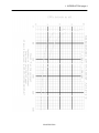
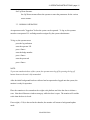
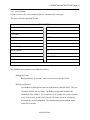
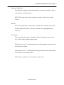
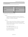
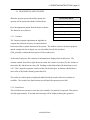
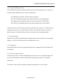
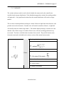
WASTE MONITOR MODEL BM-286A OPERATING AND SERVICE MANUAL Version 1.00z December 20, 2004 BM-286A TABLE OF CONTENTS 1. INTRODUCTION..................................................................................................................... 1 1.1. SCOPE AND PURPOSE OF MANUAL.................................................................... 1 1.2. GENERAL DESCRIPTION ....................................................................................... 1 1.3. SPECIFICATIONS ..................................................................................................... 2 2. INSPECTION AND INSTALLATION................................................................................... 5 2.1. INSPECTION.............................................................................................................. 5 2.2. INSTALLATION........................................................................................................ 6 3. OPERATING INSTRUCTIONS ............................................................................................. 7 3.1. GENERAL OVERVIEW............................................................................................ 7 3.2. POWER-UP AND SELF-TESTS ............................................................................... 8 3.3. NORMAL OPERATION.......................................................................................... 11 3.4. PROGRAMMING THE SYSTEM........................................................................... 13 3.5. DIAGNOSTICS AND UTILITIES........................................................................... 22 3.6. REPORTS ................................................................................................................. 24 3.7. INITIAL INSTALLATION CHECKLIST ............................................................... 25 3.8. WASTE STREAM SET-UP WORKSHEET............................................................ 27 4. THEORY OF OPERATION.................................................................................................. 28 4.1. UNIT OPERATION.................................................................................................. 28 4.2. COMPONENTS........................................................................................................ 28 5. MAINTENANCE .................................................................................................................... 33 5.1. OPERATOR MAINTENANCE ............................................................................... 33 5.2. CALIBRATION........................................................................................................ 33 5.3. DISCRIMINATOR ADJUSTMENT........................................................................ 36 5.4. WEIGHT CALIBRATION ....................................................................................... 37 5.5. CALIBRATION CHECK-LIST ............................................................................... 38 6. TROUBLESHOOTING ......................................................................................................... 39 6.1. DIAGNOSTIC AIDS ................................................................................................ 39 6.2. FAULT ISOLATION................................................................................................ 40 6.3. COMPUTERS........................................................................................................... 41 6.4. SIGNAL INTERFACE ASSEMBLY AND DETECTORS ..................................... 41 APPENDIX .................................................................................................................................. 42 A. WARRANTY .......................................................................................................................... 42 B. GLOSSARY ............................................................................................................................ 43 C. FORMULAS ........................................................................................................................... 45 C.1. ACTIVITY FROM COUNTS .................................................................................. 45 C.2. EFFICIENCY ........................................................................................................... 45 C.3. N*SIGMA ALARM LEVEL ................................................................................... 45 C.4. RELIABLE DETECTABLE ACTIVITY (RDA) FORMULA................................ 46 C.5. SIGNAL TO BACKGROUND RATIO................................................................... 46 C.6. VARIANCE.............................................................................................................. 47 D. CONFIGURATION TRACKING SHEET.......................................................................... 48 E. PARTS ..................................................................................................................................... 49 E.1. RECOMMENDED SPARE PARTS ........................................................................ 49 E.2. SPARE PARTS ORDERING INFORMATION...................................................... 49 F. DRAWINGS ............................................................................................................................ 50 1. INTRODUCTION page 1 1. INTRODUCTION 1.1. SCOPE AND PURPOSE OF MANUAL This manual is designed to enable operating and service personnel to properly operate and care for the BM-286A. Since applications are necessarily site-specific, operation procedures are given in general terms. Service and repair are covered to the board level. Anything more complex than this requires that the instrument or assembly be returned to TSA. 1.2. GENERAL DESCRIPTION TSA’s Barrel Monitor, Model BM-286A, is a large barrel monitoring device, designed to screen bulky items of up to 1,000 pounds for radioactive contamination. It uses six plastic scintillation detectors, one on each side of the chamber. An optional sodium iodide scintillation detector can be provided for spectral monitoring. Operation of the instrument is controlled from a touch screen LCD monitor or optionally using an external computer keyboard. All access is controlled by user-assigned password protection. A printer can be connected for report printing or the printing of container data labels. The instrument performs a self-test and acquires a new background count each time it is powered up. It also monitors its own operation during normal use and indicates any failures. It runs continuously, updating backgrounds whenever no weight is detected inside the chamber. A new count is initiated every time a door open/door close sequence is detected. The BM-286A displays the total activity, scaled to appropriate units (µCi, nCi, etc.) and specific activity in pCi/gram. These units are also included in reports and data sample information that are created by the unit. The unit operates on 120Vac, 60Hz power with circuit breaker protection. Model BM-286A 1. INTRODUCTION page 2 1.3. SPECIFICATIONS Sensitivity: See graph on page 4 (section 1.3. Specifications). Detectors: Two 12"w x 24"h x 1.5"d (30 x 47 x 3.75cm) plus Four 12"w x 35"h x 1.5"d (30 x 90 x 3.75cm) plastic scintillation detectors coupled to photo-multiplier tubes via light pipes. Total detector volume is 3,384 in3 (55 liters) Optional Detector: One 3" x 3" NaI(Tl) Display: Super VGA color flat panel monitor with touch screen Power: Input: 120V, 60 Hz, 3A Requirements: 115/230 Vac, 47 – 63 Hz, 400 VA Time: Scan 1 to 50,000 seconds, user-programmable Background : 20 to 10,000 seconds, user-programmable Serviceability: May be repaired to the board/subassembly level in the field Dimensions: Overall: 75" h x 44" w x 44" d (191 x 100 x 110cm) Internal Cavity: 12" h x 12" w x 12" d (30 x 30 x 30cm) Model BM-286A 1. INTRODUCTION page 3 Weight: Unit ≈12,000 lb (5,455kg) with 1.75" lead shielding Sample Weight: 5 to 1,000 pounds (2.3 to 455kg) Environmental: Temperature: 32 to 100˚ F (0 to 40˚C) operating; 0 to 120˚ F storage Humidity: 0 to 95% Relative Humidity (non-condensing) Accessories: (included with system) VGA color monitor, 101 key keyboard Components: (optional) Printer, NaI(Tl) detector and 1,024 channel MCA for spectral isotopic identification Model BM-286A 1. INTRODUCTION page 4 Model BM-286A 2. INSPECTION AND INSTALLATION page 5 2. INSPECTION AND INSTALLATION The following procedures should allow on-site personnel to correctly install and set up the BM-286A for normal operation. Follow the procedures in the order given. It is recommended that a copy of the Initial Installation Checklist (section 3.7.) be filled out after initial installation and whenever the BM-286A is put into service after prolonged storage. Use the Configuration Tracking Sheet (Appendix D) for maintenance and tracking instrument modifications. If necessary, consult TSA Systems for assistance in case of unusual site conditions or special requirements. 2.1. INSPECTION 2.1.1. Incoming Inspection: Immediately inspect the instrument for mechanical damage, scratches, dents or other defects. It should be examined for evidence of concealed, as well as external damage. 2.1.2. Damage Claims: If the instrument is damaged in transit or fails to meet specifications upon receipt, notify the carrier and TSA Systems immediately. Shipping cartons, packing materials, waybills and other such documentation should be preserved for the carrier’s inspection. TSA will assist in providing replacement or repair of the instrument if necessary. 2.1.3. Storage: Care should always be taken to avoid subjecting the instrument to severe mechanical or environmental shock. The instrument should be stored in a dry location and in a temperature range of 0 to 50˚ C, temperature constant location. Model BM-286A 2. INSPECTION AND INSTALLATION page 6 2.1.4. Shipping: Before returning the instrument for any reason, notify TSA Systems of the difficulty encountered, giving the model and serial numbers of the equipment. TSA will furnish specific shipping instructions. 2.2. INSTALLATION The instrument is complete and ready to operate when it is shipped. The touch screen LCD monitor, stored inside the chamber, must be connected to the NT computer by removing the top and right side panels. Mount the monitor with the screws provided on the right side and connect the cables marked 1, 2, and 3 (power, VGA, COM2) to the back of the Windows NT computer chassis. The optional keyboard is stored next to the computer and can be connected for data entry. The power cord located on the left side of the unit plugs into a standard 115 volt, 60 Hz ac receptacle. When the instrument is installed at its operating location, the set-up and operating procedures should be performed as described in General Overview (section 3.1.). Model BM-286A 3. OPERATING INSTRUCTIONS page 7 3. OPERATING INSTRUCTIONS 3.1. GENERAL OVERVIEW When the BM-286A is initially installed at its operating location, the operating parameters must be adjusted to meet the local conditions and testing requirements. Most of the adjustments are accessed via the software set-up mode. A touch screen keyboard will appear any time you are required to enter data into the instrument. Use the provided stylus to help in accessing buttons and entering information. An Initial Installation Set-Up Checklist (section 3.7.) and a Waste Stream Programming Worksheet (section 3.8.) can be found at the end of this section. The Set-Up Checklist should be duplicated and filled in for each test source that will be used with the system. A copy of the completed form should be kept in a convenient location as a reference for identifying future problems. The Waste Stream Programming Worksheet contains entries for each of the operating parameters in the individual waste streams. The instrument permits up to 20 pre-programmed waste streams, and the form may be copied as required to assist in programming these waste streams. The set-up mode is password protected, with two levels of user access provided. Both level 0 and level 1 operators have access to the normal operation of the BM-286A. Operators with level 0 (administrative) access may change operating parameters and change discriminator settings. Determining the operating parameters is largely dependent on local requirements and conditions. Model BM-286A 3. OPERATING INSTRUCTIONS page 8 3.2. POWER-UP AND SELF-TESTS The main power switch is located on the left hand side of the BM-286A. When the instrument is turned on the computer performs a Power-On Self-Test (POST) which checks and initializes the system hardware. At the end of this test, an audible ’beep’ is sounded. If the beep fails to sound during start-up, there may be a problem with audible alarms during sample testing. The operating system (Windows NT) is then loaded from the hard disk. The program can be run from the Startup Menu under Program Files. If the system fails to power up correctly, try turning the power switch on the side of the controller module off for a few seconds and then back on to re-initiate the tests. Once the computer has successfully completed its tests and the program is executing, the instrument will display the normal background collection screen. The detector windows should be gray, and a pop-up window displaying the message "GETTING nn SECOND BACKGROUND" will appear. The chronograph will show the remaining time of the count. As soon as the background count is completed (the time is determined by the current entry in the Set-Up Menu), the operator must log-on before any operations can be preformed. A scale tare is recommended at this time. After the scale tare is complete, the blue "READY" window will light, and the current background in counts per second will be displayed in black text on a blue background. The detector windows are positioned graphically to indicate which detectors they represent. Model BM-286A 3. OPERATING INSTRUCTIONS page 9 If a background fault condition (either high or low) is detected the detector windows will be displayed in black text on a magenta background. The offending detectors will display either "**HI**" or "**LO**". NOTE: The fault condition must be corrected before operation will be allowed. An access menu is displayed across the bottom of the screen. ACCESS MENU Level One Access Level Zero Access (password protected) Print sample data Set-up menu TARE (scale) Utilities Bkg Rec (record background) Set-up waste streams Operator log-on Operator log-off Invokes the PCAP software (optional) The available functions in the access menu are defined as follows: Sample Data: Sample data prints out a sample of data to the printer. This is useful to verify alignment when installing label stock. The data included in the print out is: waste stream, date, time, ID, message, activity, specific activity, weight, net cps, and user. Tare Scale: Tare scale prompts the operator to verify that the chamber is empty, and press the OK button to tare the scale. Model BM-286A 3. OPERATING INSTRUCTIONS page 10 Background Record: Background record is necessary for future use. User Log-On: User log-on is used to log a new user onto the system. A user must be logged on to the system before any samples are tested. The new user will be prompted for both name and badge number. Logging on a new user automatically logs off the existing user. Initial Set-Up: For initial setup, use this information: User name - TIM, Badge - 11, Password - OK. Delete this record after you have entered your information. User Log-Off: User log-off is used to log the current user off the system to prevent unauthorized access when the machine is left unattended. PCA-II: PCA II is optional. Set-Up: Set-Up allows the system’s operating parameters to be examined or changed. Utilities: The utilities function provides access to diagnostics, user setup and shut down utilities. Details of these functions are provided in the appropriate sections of this manual. Model BM-286A 3. OPERATING INSTRUCTIONS page 11 Set-Up Waste Streams: Set-Up Waste streams allows the operator to enter the parameters for the various waste streams. 3.3. NORMAL OPERATION An operator must be "logged on" before the system can be operated. To log on, the operator must have an operator I.D. and badge number assigned by the system administrator. To log on, the operator must: press the log on button enter the operator I.D. press <Enter> enter the badge number press <Enter> enter the password press <Enter>. NOTE: To prevent unauthorized use of the system, the operator must log off by pressing the log off button whenever the unit is left unattended. After the initial background has been collected and an operator has logged onto the system, the monitor is ready for operation. Place the container to be scanned on the weight scale platform and close the door to initiate a scan. Note that all detector windows turn gray while the door is open. The monitor will read the scale when the door is closed. If no weight (<5 lb) is detected in the chamber, the monitor will return to background update mode. Model BM-286A 3. OPERATING INSTRUCTIONS page 12 If more weight (>5 lb), but less than the programmed minimum weight is detected, the screen will display "Insufficient Weight". The operator must remove the weight from the chamber and press OK to continue operation. If the weight is "?" the programmed minimum weight, the operator will be prompted to select the appropriate waste stream from a menu. If an invalid waste stream is entered (i.e. no efficiency) the operator will be given the opportunity to correct the entry. If a valid waste stream is entered the item to be scanned will be compared to the maximum weight of the waste stream. If the item is "?" the maximum weight of the waste stream a dialog box will appear with the maximum weight of the waste stream exceeded. At this point the article may be removed or the operator may press OK as prompted by the monitor and the waste stream menu will reappear. After a valid waste stream is entered, the operator will be prompted for an Item I.D., a touch screen keyboard will appear. Press <Enter> if no Item I.D. is required. The monitor will then scan the item and show the time to completion. When the scan is complete, the unit will emit a "chime". If the activity measured is greater than the alarm threshold: The alarm window at the top of the screen will turn red and a scan result box will appear with the user-programmed alarm message in yellow letters on a blue background. If the activity measured is less than the alarm threshold: The clear window at the top of the screen will turn blue and a scan result box will appear with the user-programmed alarm message in yellow letters on a blue background. Model BM-286A 3. OPERATING INSTRUCTIONS page 13 The print button can be touched in the scan results box for a print out of the scan data. The data includes waste stream name, date, time, waste item I.D., scan message, activity in nCi, specific activity in (nCi/kg), kilogram weight, net counts per second, and user information. The screen will display the results of the scan, and hold this information until the door is opened. When the door is opened, the scan information is cleared. The system is now ready for a new sample. 3.4. PROGRAMMING THE SYSTEM Programming the system can only be done by a "level 0 operator". The general set-up function sets the global system parameters, which are detailed in the Set-Up Menu (section 3.4.1.). Setting up waste streams involves setting the parameters for the individual waste I.D.s. These parameters are detailed in Set-Up Waste Streams (section 3.4.2.). When a large amount of data is to be entered we suggest you use the external keyboard. Model BM-286A 3. OPERATING INSTRUCTIONS page 14 3.4.1. Set-Up Menu: Set-up is used to refer to the parameters that are common to all waste types. The menu will look something like this: SET-UP MENU Bkg Time 120 Bkg Method Rolling Low Alarm 0 High Alarm 10000 Var Time 60 Var Trials 3 Units of Weight Lbs Min Weight lbs 10 Reports All BM I.D.: ABCDEFGH User Stream 0 OK The available menu parameters are defined as follows: Background Time: Background time, in seconds. Enter a value between 20 and 10,000. Background Method: Two methods of background count are incorporated in the BM-286A. They are selectable from the Set-Up Menu. The Rolling background method is the standard for TSA products. For a count time of N seconds, the count is updated every N/10 seconds, and the sum of the last 10 count periods are averaged to determine the current background. The Standard background method simply counts for N seconds. Model BM-286A 3. OPERATING INSTRUCTIONS page 15 Low Alarm: Low alarm level in CPS, is the point at which the unit will generate a FAULT condition. Enter a value between 0 and 1,000. The counts from each detector are compared to this value; if the count from any detector falls below this value the unit will enter a FAULT mode. High Alarm: High alarm level in CPS, is the point at which the unit will generate a FAULT condition. Enter a value between 500 and 32,000. The counts from each detector are compared to this value; if the count from any detector exceeds this value the unit will enter a FAULT mode. Variance Time: This menu parameter sets time per variance test, in seconds. Enter a value between 10 and 100. Refer to Variance (section 3.5.1.) for details. Number of Trials: This menu parameter sets the number of iterations for the variance test. Enter a value between 3 and 10. Units of Weight: This menu parameter selects either pounds or kilograms as the unit of weight for display and report purposes. Minimum weight is always in pounds, and specific activity is always in pCi/gram regardless of this selection. Reports: This menu parameter enables writing a report to disk. The choice is from three options: ALL, ALARM, or NONE. Refer to Reports (section 3.6.) for details. Model BM-286A 3. OPERATING INSTRUCTIONS page 16 Minimum Weight Lbs: The minimum weight in pounds required before a scan may be initiated. Enter a value between 5 and 500 pounds. NOTE: This value must be input in pounds regardless of the units of weight selected. BM I.D.: This is the identification for the monitor. This ID will be included in the reports and data sample information. Enter any combination of eight alpha-numeric characters. User Stream: This entry allows the system administrator to allow all operators access to any one, or all 20 of the available waste streams. If this entry is set to "0", the operator must select the appropriate waste stream for each item to be scanned. If this entry is set to 1 - 19, the operator will only be able to use the waste stream selected by the system administrator. NOTE: This is a global entry that applies to all operators. Model BM-286A 3. OPERATING INSTRUCTIONS page 17 3.4.2. Set-Up Waste Streams: The following parameters must be set for each waste stream to be used: WASTE STREAM PARAMETERS Waste I.D. Alarm Message Count Time Clean Message Count Display Maximum Weight MCA Data Efficiency Alarm Type Alarm Level A detailed description of each parameter entry follows: Waste I.D.: This parameter provides a description of the waste stream. The operator may program up to 16 alpha-numeric characters to provide a unique reference for each waste stream. The existing I.D. will be displayed. Count Time: Scan time, in seconds. Enter a value between 1 and 50,000, or "0" for minimum count time. If minimum count time is selected, the system will automatically calculate the minimum time required to scan the item. The following are assumed for automatic scan time calculation: bkg = background in counts/second consig = confidence sigma (fixed at 1.65Õ or 95%) fasig = false alarm sigma (fixed at 2.33Õ or 1/100) alev = alarm level in cps/efficiency efficiency = waste stream efficiency Model BM-286A 3. OPERATING INSTRUCTIONS page 18 The actual formula used to determine minimum scan time is derived from the RDA formula found in Appendix C. Formulas. The specific alarm level uses the initial "quick weight" x 0.9 to determine the alarm level used for scan time calculations. This provides a safety margin in the calculations. The final alarm level comparison is based on the more accurate weight normalized to count time. NOTE: The minimum count time calculation is disabled if N*Sigma alarm type is selected. If N*Sigma alarm type is selected in conjunction with a "0" count time, the count time will automatically be set to 30 seconds. Count Display: Selects the method used for displaying counts on the screen and in the reports. The background counts will always be displayed in counts/second. The count display options only control the display after a scan. The available options are: 1. Total counts per scan: Displays total counts per scan time. 2. Net counts per scan: Displays counts per scan time above background. 3. Total counts per second: Displays total counts per second. 4. Net counts per second: Displays counts per second above background. MCA Data: MCA data is an optional entry feature. Model BM-286A 3. OPERATING INSTRUCTIONS page 19 Alarm Type: Alarm type selects the method of generating a radiation alarm. The available options are: 1. NSIG: ((N*1background) + background) 2. DPM: Disintegrations per minute above background 3. SPACT: Specific Activity in pCi/gram Alarm Message: This parameter entry is the message that will be displayed if the alarm level is exceeded. This may be up to 22 alpha-numeric characters. This message will be included on the data sample information and in the reports. Clean Message: This parameter entry is the message that will be displayed if the alarm level is not exceeded. This may be up to 22 alpha-numeric characters. This message will be included on the data sample information and in the reports. Maximum Weight: Enter a maximum allowable weight, in pounds. This is used to determine if the item to be scanned is within the waste stream weight limits. Model BM-286A 3. OPERATING INSTRUCTIONS page 20 Efficiency: This parameter entry represents the efficiency of the detectors, in percent, to the source activity. This value is used in calculating the activity. This value may be either entered manually or automatically calculated by the BM-286A. Press on the white box and enter a value, or press "auto" to allow the unit to calculate the efficiency. 1. Manual entry method: Enter an efficiency in percent. Entering a <0> will disable the current waste I.D. 2. Automatic calculation: The operator will be prompted for a count time (in seconds) and the calibration source activity (in nanocuries). Press "BEGIN" at which time a START button will appear. Press the "START" button and the unit will then take an nn second background. The operator will be prompted to place the source in the center of the chamber and press "START" to accumulate an nn second count with the source in the chamber. The efficiency will be displayed in the efficiency window. Model BM-286A 3. OPERATING INSTRUCTIONS page 21 Alarm Level: The operator will be prompted for the alarm level (depending on the alarm type selected above). Enter the alarm level (above background) in the appropriate units. The previous value will be displayed, and will only be accepted by entering it again, or a new value may be entered. 1. DPM: Radiation alarm level in disintegrations per minute. Enter a value between 10,000 and 1,000,000,000. This is the level above background that will generate a radiation alarm when the DPM alarm type is selected. NOTE: This value is used only when the Alarm Type is set to DPM. 2. N*Sigma: Radiation alarm level in N*Sigma (N*1background + background). This is the count level that will generate a radiation alarm when N*Sigma alarm type is selected. NOTE: This value is used only when the Alarm Type is set to N*Sigma. 3. SpAct: Radiation alarm level, above background, in pCi per gram. Model BM-286A 3. OPERATING INSTRUCTIONS page 22 3.5. DIAGNOSTICS AND UTILITIES When the operator presses the utilities button, the operator will be presented with the Utilities Menu. UTILITIES MENU Variance Scale Reset Press the appropriate button from the menu as shown. Detector Efficiency Check The functions are as follows: Operator Set-up Shut Down 3.5.1. Variance: OK The Variance program implements an algorithm to compute the statistical accuracy of counts obtained from each of the six plastic detectors in the system. The number of passes run by the program, and the sample time for each pass, are user selectable from the Set-Up Menu. (TSA generally recommends three passes of 60 seconds each.) At the end of each pass, four columns of information are displayed for each detector. The columns contain, from left to right, the mean counts, the variance in counts (S2), the variance to mean ratio (R), and the mean value of R. Readings in the third column (R) should not exceed 0.49. TSA’s normal acceptance criterion is that, for the third pass, no detector should show a mean value of R (fourth column) greater than 0.30. The results of each iteration are displayed and held until the results of the next iteration are available. The results of the final iteration are held until the operator presses OK. 3.5.2. Scale Reset: This tool allows the operator to reset the scale controller if a problem is suspected. This process will take approximately 30 seconds and a message will be displayed during the operation. Model BM-286A 3. OPERATING INSTRUCTIONS page 23 3.5.3. Detector Efficiency Check: The Calculation Set-up box will appear and the operator will be prompted for a count time (in seconds) and the calibration source activity (in nanocuries). Press BEGIN at which time a START button will appear. Press the START button and the unit will then take an nn second background. The operator will be prompted to place the source in the center of the chamber. Press START to accumulate an nn second count with the source in the chamber. Calculate efficiencies of the detectors and the overall efficiency of the unit. The efficiencies are displayed, but not stored. Overall efficiency which is the sum of the efficiencies for the six plastic detectors is calculated with a test source in the center of the counting chamber. 3.5.4. Operator Setup: Operators can be deleted or added by name, badge number, password and level of accessibility (Admin. or User). Be careful in selection of administrative access. 3.5.5. Shut Down: Pressing this button will close the program and release the computer back to the Windows NT environment. 3.5.6. Detectors, Scale, and Disc.: This window provides us with a troubleshooting tool as well as a way to adjust the upper and lower level discriminators. Refer to Discriminator Adjustment (section 5.3.) for detailed instructions. The detector counts and scale weight are displayed and updated every two seconds. Model BM-286A 3. OPERATING INSTRUCTIONS page 24 3.6. REPORTS A file called REPORT.DBF is located in the BM286A directory, if the file does not exist it will be created, and is appended every time a scan is to be recorded. This file is in a data base format and can be ported over to many different data bases. The information contained in the file is the waste stream name, date, time, entered waste item id, scan message, activity (nCi), specific activity (nCi/kg), kilogram weight, net counts per second, user logged on at that time. The activity, specific activity, kilogram weight, and net cps are stored in float format. 3.6.1. Standard Report: The (Standard) Report output is controlled from the Set-Up Menu. (section 3.4.1.) The following three options are offered: None: None disables report generation altogether. Alarms: Alarms will generate a report only for samples that are found to be above the alarm level. All: All causes a report to be generated and stored on disk every time a scan is completed. Model BM-286A 3. OPERATING INSTRUCTIONS page 25 3.7. INITIAL INSTALLATION CHECKLIST Plastic Detectors: Background: __________ Counts Test Source: Isotope: __________ Serial No.: __________ Activity; __________nCi Date of latest assay: __________ No. of Counts: Right: __________ Top: __________ Left: __________ Bottom: _________ Back: __________ Door: __________ Right: __________ Top: __________ Left: __________ Bottom: _________ Back: __________ Door: __________ Total: __________ Efficiency: Total: __________ Discriminator Settings: LLD: ___________ ULD: __________ Model BM-286A 3. OPERATING INSTRUCTIONS page 26 Set-Up Parameters: Background Time: __________ seconds Background Method: [ ] Rolling [ ] Standard Variance Time: __________ seconds Number of Trials: __________ Low Alarm Level: __________ counts/second High Alarm Level: __________ counts/second Minimum Weight: __________ pounds Units of Weight: [ ] Lbs [ ] Kg Reports: [ ] All [ ] Alarms [ ] None User Stream: __________ BM I.D.: __________ Performed by: ____________________________ Date: _________ Model BM-286A 3. OPERATING INSTRUCTIONS page 27 3.8. WASTE STREAM SET-UP WORKSHEET BM-286A WASTE STREAM SET-UP WORKSHEET Waste Stream number : _________________________ Waste I.D.: __ __ __ __ __ __ __ __ __ __ __ __ __ __ __ __ (16 characters max) Count Time: ____________________ seconds or "0" for minimum MCA Data (Optional): [ ] On [ ] Off Alarm Message: __ __ __ __ __ __ __ __ __ __ __ __ __ __ __ __ __ __ __ __ __ __ (22 characters max) Clean Message: : __ __ __ __ __ __ __ __ __ __ __ __ __ __ __ __ __ __ __ __ __ __ (22 characters max) Maximum Weight: ____________________ pounds Efficiency: ____________________ % Alarm Level: ____________________ [ ] DPM [ ] N*Sigma [ ] pCi/g Waste Stream number : _________________________ Waste I.D.: __ __ __ __ __ __ __ __ __ __ __ __ __ __ __ __ (16 characters max) Count Time: ____________________ seconds or "0" for minimum MCA Data (Optional): [ ] On [ ] Off Alarm Message: __ __ __ __ __ __ __ __ __ __ __ __ __ __ __ __ __ __ __ __ __ __ (22 characters max) Clean Message: : __ __ __ __ __ __ __ __ __ __ __ __ __ __ __ __ __ __ __ __ __ __ (22 characters max) Maximum Weight: ____________________ pounds Efficiency: ____________________ % Alarm Level: ____________________ [ ] DPM [ ] N*Sigma [ ] pCi/g Model BM-286A 4. THEORY OF OPERATION page 28 4. THEORY OF OPERATION The BM-286A system is a self-contained Bag/Box monitor, operated by two personal computers. 4.1. UNIT OPERATION The main computer operates in Windows NT, with a touch screen, color LCD display to monitor system operation. The system can be used with an external keyboard for operator input, and a printer to generate reports, or labels. Operating parameters can be entered from the touch screen or external keyboard via a password protected set-up menu. The DOS based computer has a TSA Systems custom counter card and sends information to the NT machine every second via RS-232. The output consists of the door position and six detector counts. The NT system continually monitors the serial data for fault conditions, and displays any errors on the computer monitor. If the system detects a fault condition, it will not allow normal operation until the fault condition is corrected. 4.2. COMPONENTS 4.2.1. Component Locations: Refer to "BM-286A Pictorial View" Drawing 1 and "BM-286A Pictorial View (Door Open)" Drawing 2 (Appendix F.). Six plastic scintillation detectors, their associated photo-multiplier tubes, voltage divider assemblies, and, optionally, a Sodium Iodide detector are contained within the walls and door of the main assembly. A slide out platform contains a third party weight scale. The scale controller is located in the top of the unit with the other electronics. Model BM-286A 4. THEORY OF OPERATION page 29 4.2.2. Computers and Power Supply: Refer to "BM-286A Wiring Diagram" Drawing 3 and"BM-286A Electronics Component Designator" Drawing 4. (Appendix F.). There are two computers, one a DOS base unit with a TSA circuit card (CIF-553) and the second a Windows NT machine. Communication between them is handled by RS-232 via COM1 on both machines. The computers both have passive back planes with plug in computer cards. DOS unit: 8 megabytes (MB) of RAM, a hard disk drive, and a 3 ½" floppy drive. The hard drive contains the DOS operating system and operating program. The program directory includes a support file with the discriminator settings. WINDOWS NT: 32 megabytes (MB) of RAM, a hard disk drive, and a 100 MB Zip drive. The user, setup, and waste streams are stored on the hard disk. The machine receives data from the DOS machine on COM1, scale data on COM3, and touch screen data on COM2. 4.2.3. Backplane Card, RCS-130: Refer to "RCS-130 Schematic Diagram" Drawing 10, "RCS-130 Component Designator Front" Drawing 11 and "RCS-130 Component Designator Rear" Drawing 12 (Appendix F.). The backplane card is a passive board that contains these connectors: • Eleven - 44 pin edge card connectors • One - 50 pin ribbon cable connector • One - 34 pin ribbon cable connector • Ten - MHV chassis connectors • One - 5 pin power connector • One - 8 pin external connector for control Model BM-286A 4. THEORY OF OPERATION page 30 4.2.4. Channel Card, RCS-110: Refer to "RCS-110 Schematic Diagram" Drawing 6 and "RCS-110 Component Designator" Drawing 7 (Appendix F.). VR1, VR2, and VR3 regulate the ±15 volt power supply voltages to ±12 volts and +5 volts for use on this card. The card is equipped with a series of test points for discriminator, pulse amplitude, and high voltage measurements. The high voltage test point is a 100 to 1 divider. U12, U13, and the associated circuitry make up the regulated high voltage power supply. High voltage (less than 1,500Vdc) is supplied to the MHV connector on the backplane via the 44 pin edge card connector. Pulses from the detectors are input through shielded MHV cables to the rack control module, and then into the inputs on the backplane to the channel boards. The analog signal is decoupled by C46, amplified by U8 and U7, and sent to the single channel analyzer. The second amplifier/SCA channels are not used in this application. The SCA is made up of two voltage comparators (U6). The amplified signal must fall between the LLD and ULD levels to be digitized and sent to the counters in the computer. These voltages can be manually adjusted, or set by the computer. In either case, the actual adjustment is done on the RCS-120 card. Any pulses having an amplitude greater than the LLD and less than the ULD pass through the comparator circuits and generate a digital pulse (U10). These pulses are sent to a differential line transmitter (U2) and on to the line receivers on the CIF-553 Computer Interface board, which plugs into the ISA bus in the computer. Model BM-286A 4. THEORY OF OPERATION page 31 4.2.5. Discriminator Card, RCS-120: Refer to "RCS-120 Schematic Diagram" Drawing 8 and "RCS-120 Component Designator" Drawing 9 (Appendix F.). The ±15 volt power supply voltages are regulated to ±12 volts and +5 volts used on this card. The card is lined with test points for measurement of the discriminator levels. U7 generates the negative 10 volt reference used by the serial digital to analog voltage converters (U1,5,8,10). The converters are selected by the computer through the CIF-553 via U3; a programmable gate array. Serial data and clock are also generated by the CIF differential drivers and U4 receiver decodes this information. Voltage outputs from the converters go to operational amplifiers and transistor drivers to each RCS-110 card by the 44 edge card connector. 4.2.6. Computer Interface Board, CIF-553: Refer to "CIF-553 Schematic Diagram" Drawing 17 and "CIF-553 Component Designator" Drawing 18 (Appendix F.). This board is located in the DOS machine. TSA Systems manufactures the CIF-553 board for use in their PC based products. The CIF-553 has the following characteristics: • Twenty-one - 16 bit counters • Three - 8 bit I/O ports • Twenty-four - differential line receivers • Four - differential line transmitters • Two - ribbon connectors (50 & 34 pin) which interface with the backplane (RCS- 130) • The counters are used for the radiation detectors, motor encoders, etc. • The ports are used for system control and discriminator setting. • Port "C" has 4 differential line drivers and line receivers. • The Address of the card is 1000. Model BM-286A 4. THEORY OF OPERATION page 32 4.2.7. Receiver Board, RECV-1: Refer to "RECV-1 Schematic Diagram" Drawing15 and "RECV-1 Component Designator" Drawing 16 (Appendix F.). The receiver board is a quad, differential line receiver. This board converts the differential inputs to +5 volt logic outputs. There is a +5 volt regulator on board. This board controls the solid state relay for power to the scale controller. 4.2.8. Transmitter Board, TRANS-1: Refer to "TRAN-1 Schematic Diagram" Drawing13 and "TRAN-1 Component Designator" Drawing 14 (Appendix F.). The transmitter board is a quad, differential line transmitter. This board receives +5 volt logic inputs and converts them to differential outputs. There is a +5 volt regulator on board. This board has the input from the door position sensor. 4.2.9. Low Voltage Power Supply: Low voltage (+5 and ±12Vdc) for the system are supplied by an open frame power supply. 4.2.10. Scale Controller: The controller is located on top of the board rack system and displays the current weight in pounds. This unit receives its power from the solid state relay controlled by the RECV-1 board and DOS computer. The NT machine sends and receives serial ASCII data from the unit via COM3. Model BM-286A 5. MAINTENANCE page 33 5. MAINTENANCE 5.1. OPERATOR MAINTENANCE The slide tracks on the weight scale platform should be greased monthly. The hinges and door latch do not require lubrication. 5.2. CALIBRATION The electronic circuitry has proven to be very stable over long periods of time. However, the following calibration should be performed at least annually to ensure reliable operation and accurate measurements. There is a Calibration Checklist (5.5.) at the end of this section. Copies should be made, and filled out each time the system is calibrated. NOTE: The high voltage affects the pulse amplitude, so the high voltage must be tested before the RCS-110 amplifiers are calibrated. This procedure should be performed only by qualified personnel! Calibration equipment required: DVM with 10MÛ input impedance Oscilloscope with >20 MHz bandwidth Test Source (5-12 µCi of 137Cs) Remove the right side face plate to gain access to the RCS boards. Refer to"BM-286A Pictorial View (Door Open)" Drawing 2 (Appendix F.). Model BM-286A 5. MAINTENANCE page 34 5.2.1. Channel Boards, RCS-110: Refer to "RCS-110 Schematic Diagram" Drawing 6 and "RCS-110 Component Designator" Drawing 7 (Appendix F.). Oscilloscope set-up: 1 µsec HORIZONTAL\DIV 1 volt VERTICAL\DIV This procedure must be performed for each detector channel in the system for a normal calibration. NOTE: The following adjustments are factory preset, and should not require further adjustment. R15 should be turned maximum ccw to prevent inducing noise into the beta amplifier. R8 & R23 are amplifier offsets, and should not require further adjustment. The factory settings are -0.005 volts at TP13 and TP1, respectively. 5.2.1.1. First Stage Pulse Amplitude: The first stage pulse amplitude is set by adjusting the high voltage. NOTE: TP17 provides a divide by 100 test point for the high voltage. This test point should be monitored during calibration to verify that the high voltage does not exceed 1,400 volts, or 14 volts at this test point. WARNING: Exceeding 14 volts at TP17 could cause permanent damage to the photo-multiplier tube. Model BM-286A 5. MAINTENANCE page 35 Connect the DVM between TP16(-) and TP17(+). Connect the oscilloscope between TP16(ground) and TP15(input). Place 137Cs source as close to the center of the detector under test. Refer to Drawing 20 (Appendix F.) for an example of a typical pulse profile. Adjust the oscilloscope controls to provide a similar display. Adjust R42 for 1.0 volts peak pulse amplitude. Verify that TP17 is <14 volts. Set oscilloscope: 2 volts VOLTS\DIV Move oscilloscope probe to TP13. Adjust R5 for 4 volts peak pulse amplitude. NOTE: Pulses of all amplitudes will be observed on the scope. Refer to the typical pulse profile on Drawing 20 (Appendix F.). However there should be a noticeable increase in the display intensity for those pulses having amplitudes of 4.5 volts or less relative to those of greater amplitudes. If this is not readily apparent, try adjusting the scope intensity control. Model BM-286A 5. MAINTENANCE page 36 5.3. DISCRIMINATOR ADJUSTMENT The Upper and Lower Level Discriminators (ULD & LLD) set the maximum and minimum energy levels at which the system accepts counts. The LLD must be set high enough to prevent system noise from being amplified and counted. The DOS machine sets the levels on the RCS-120 discriminator card but gets its values from the NT machine. The upper and lower level discriminators’ adjustment range is 0 keV to approximately 1.5 MeV. These levels are controlled by entering the Utilities Menu and pressing the Detectors, Scale and Disc. button. The Set Discriminator box and detector counts will appear with the previous upper and lower settings. Using the up and down arrows the values for upper and lower can be changed but are not sent to the DOS machine until the send button is pressed. Observe the counts in the detector boxes to insure you have not reached the lower level noise threshold. The approximate energy level in keV can be obtained by multiplying the settings by 150. The exact value may vary slightly due to variations in the detectors and electronics. For initial set-up, a good starting point is: SETTINGS FOR PLASTIC DETECTORS NOTE: LLD = 0.3 volts = 45 keV If either level is changed you must always ULD = 10.0 turns = 1.5 MeV recalculate all waste stream efficiencies. The unit will also acquire a new background when leaving the Utilities Menu. Always run a variance after adjusting the levels. Model BM-286A 5. MAINTENANCE page 37 5.4. WEIGHT CALIBRATION The third party scale was calibrated at the factory and should not need calibration. If a problem occurs, contact TSA Systems for assistance. Model BM-286A 5. MAINTENANCE page 38 5.5. CALIBRATION CHECK-LIST High Voltage: HHV #1: __________ VDC HHV #2: __________ VDC HHV #3: __________ VDC HHV #4: __________ VDC HHV #5: __________ VDC HHV #6: __________ VDC New Voltage Setting (if adjusted): ____________________ HHV #1: __________ VDC HHV #2: __________ VDC HHV #3: __________ VDC HHV #4: __________ VDC HHV #5: __________ VDC HHV #6: __________ VDC Pulse Amplitude - Plastic Detectors: Test Source: Isotope:__________ Activity: __________ µCi Serial No.:________ Date of latest assay:__________ Peak Volts: Right: __________ Top: __________ Left: __________ Bottom: _________ Back: __________ Door: __________ Right: __________ Top: __________ Left: __________ Bottom: _________ Back: __________ Door: __________ New Readings (if adjusted): Variance (final readings only): Number of trials: __________ Variance time: __________ Right: __________ Top: __________ Left: __________ Bottom: _________ Back: __________ Door: __________ Performed by: _____________________________Date: ___________________ Model BM-286A 6. TROUBLESHOOTING page 39 6. TROUBLESHOOTING This guide is designed so that on-site personnel can service the BM-286A and effect necessary minor repairs. It covers procedures and parts down to the board level. Any other problems should be referred to factory authorized service personnel. Unauthorized repair voids warranty. 6.1. DIAGNOSTIC AIDS There are several diagnostic tools available to help isolate problems in the unit. Access to the diagnostics is available only to level 0 users with a valid password. The system administrator normally controls the password access. Press Utilities from the operating screen to access the Utilities Menu. From the Utilities Menu, the following diagnostics may be selected: 6.1.1. Scale Reset: Scale Reset will power cycle the weight scale controller. 6.1.2. Variance: Variance tests the statistics of the detector counts versus a Gaussian distribution. If periodic noise is being counted the results of the variance test will approach 1.0. Light leaks will result in a variance near 2.0. Refer to section 3.5.1 for details on the variance test. 6.1.3. Detectors, Scale and Disc.: The Detectors, Scale and Disc. diagnostic provides a convenient way to observe detector counts with a relatively quick update (2 seconds). Alarms and door position are ignored in this mode. 6.1.4. Detector Efficiency Check: Detector Efficiency Check performs an efficiency calibration on the six plastic scintillation detectors. The results are only displayed, and are not written to disk. Model BM-286A 6. TROUBLESHOOTING page 40 6.2. FAULT ISOLATION When the program is executing on the NT machine there are two small dark green boxes in the lower left hand of the display. The top box should flash light green every second. This indicates that the DOS machine has sent data to the NT machine. The bottom box should flash light green upon receiving data from the scale controller. This occurs when the door is closed or once a second when in the Utilities menu, show detector and scale, are being displayed. If the system fails to operate properly, note all anomalies, and try to determine if or how they are related. This will usually isolate the problem to some degree, and reduce the time required to repair the system. Always perform a thorough visual inspection of the suspect assemblies, looking for loose connectors, pinched and broken wires, burned components, and signs of overheating. If nothing is found during the physical inspection, locate the problem area in the following paragraphs, and isolate the defective assembly using the appropriate procedure. NOTE: Always turn the power off when connecting or disconnecting components or cables. After repairing the system, perform a calibration as outlined in Calibration (section 5.2.). Model BM-286A 6. TROUBLESHOOTING page 41 6.3. COMPUTERS To check the DOS computer a VGA monitor can be connected to see if it is running and the output to the screen will look something like this: (1,235,234,334,123,234,132) The information that is being sent is door position and six detector counts. The RS-232 data to the NT machine can be examined by using Hyperterminal. The settings should be: COM1,9600,N,8,1 Use standard troubleshooting procedures on the NT machine. 6.4. SIGNAL INTERFACE ASSEMBLY AND DETECTORS Channel boards (RCS-110) may be substituted with system power on, but the power must be turned off before changing the discriminator cards (RCS-120). This will ensure that the discriminator settings are updated. NOTE: If channel cards are replaced permanently, the channels affected must be recalibrated. Model BM-286A APPENDIX A. WARRANTY page 42 APPENDIX A. WARRANTY STANDARD WARRANTY FOR TSA SYSTEMS INSTRUMENTS TSA Systems, Ltd., warrants this instrument to be free from defects in workmanship and materials for a period of twelve months from the date of shipment, provided that the equipment has been used in a proper manner and not subjected to abuse. At TSA’s option, repairs or replacements will be made on in-warranty instruments without charge at the TSA factory. Warranty of sub-systems made by other manufacturers will be extended to TSA customers only to the extent of the manufacturer’s liability to TSA. TSA reserves the right to modify the design of its product without incurring responsibility for modification of previously manufactured units. Since installation conditions are beyond the company’s control, TSA does not assume any risks or liabilities associated with methods of installation or with installation results. Every effort is made to keep the manuals up to date and accurate. However, because TSA Systems is constantly improving and upgrading the product line, TSA can make no guarantee as to the content of current manuals. No obligations are assumed for notice of change or future manufacture of these instruments. Manufactured by TSA SYSTEMS, LTD. 14000 MEAD STREET LONGMONT, COLORADO 80504-9698 970.535.9949 FAX: 970.535.3285 Model BM-286A APPENDIX B. GLOSSARY page 43 B. GLOSSARY ADC: Analog to Digital Converter, is an integrated circuit that converts an analog signal into a binary number that can be used by the microprocessor. CPS or cps: Counts Per Second High Background Alarm/Fault: The condition that occurs if the counts exceed the programmed high background level. This condition prevents further operation until the problem is corrected. Normally set in cps. LCD: Liquid Crystal Display LED: Light Emitting Diode LLD: The Lower Level Discriminator provides a threshold, usually adjustable, that determines the lowest signal level that will be accepted as a nuclear pulse by the system’s electronics. Some systems have both upper and lower level discriminators that can be used to set a discriminator window. The discriminator window can be used to effectively reduce the background counts, and increase system sensitivity to certain isotopes. Also see ULD. Low Background Alarm/Fault: The condition that occurs if the counts fall below the programmed high background level. This condition prevents further operation until the problem is corrected. Normally set in cps. POST: Power On Self Test Model BM-286A APPENDIX B. GLOSSARY page 44 Rolling Background: This is the background accumulation method used in most of TSA’s instruments. Background accumulation is done in ten separate buffers, each buffer represents 1/10 of the total background time. As each buffer is filled, the background is updated. This results in a background update at background time/10. Initial background accumulation requires the full background time. Standard Background: Standard background requires the full background time for the initial background and updates. ULD: The Upper Level Discriminator provides a threshold, usually adjustable, that determines the highest signal level that will be accepted as a nuclear pulse by the system’s electronics. Also see LLD. Model BM-286A APPENDIX C. FORMULAS page 45 C. FORMULAS The following formulas are used in various systems manufactured by TSA Systems, Ltd. They are provided to assist in verifying system operation and to give our customers a better understanding of how the systems operate C.1. ACTIVITY FROM COUNTS Activity = Activity in nCi Eff = Decimal efficiency (i.e. 10% = 0.1.) Where: N = Net counts per second (cps – background cps) C.2. EFFICIENCY N = cps with source – background cps Where: activity = test source activity in nCi C.3. N*SIGMA ALARM LEVEL This formula calculates the minimum activity, in disintegrations per minute, that can be reliably detected under a given set of operational conditions. bkg = Background counts Where: Sigma = 1bkg N = N*Sigma value Model BM-286A APPENDIX C. FORMULAS page 46 C.4. RELIABLE DETECTABLE ACTIVITY (RDA) FORMULA This formula calculates the minimum activity, in disintegrations per minute, that can be reliably detected under a given set of operational conditions. BKG = total background counts per count time CON = confidence sigma CT = count time in seconds E = system efficiency in percent F = false alarm level in cps FA = false alarm sigma G = intermediate variance RDA = reliable detectable activity in DPM C.5. SIGNAL TO BACKGROUND RATIO The following formula is helpful is determining the optimum discriminator settings. Always perform a variance test at the final setting of the lower-level discriminator to ensure that system noise is not being introduced into the amplifier stage. Q = Quality factor Where: S = Net signal (count with source - background) B = Background count B = Background count Higher values of Q result in better sensitivity Model BM-286A APPENDIX C. FORMULAS page 47 C.6. VARIANCE The variance analyzer mode is used to check whether the counts seen by the controller are actually from the proper distribution. If the distribution approaches normal, the resulting number will approach 0. Any significant deviation from the normal distribution will result in a larger number. The two most common problems resulting in variance failure are light leaks in the detectors, and periodic noise in the electronics. Periodic noise will result in a number of about 1, a light leak will usually result in a number larger than 2. The number displayed during a variance test is the absolute value of the average of a number of these tests, with one test being performed every nn seconds. The data is valid after three iterations of nn seconds. The pass/fail criteria varies from unit to unit and is included in the variance section of the manual on most units. R = the quality factor C = each of the individual counts Where: N = number of counts taken _ R = mean variance I = number of iterations Model BM-286A APPENDIX D. CONFIGURATION TRACKING SHEET page 48 D. CONFIGURATION TRACKING SHEET TSA MODEL NUMBER:______________ SERIAL NUMBER:________________ SOFTWARE VERSION:_______________ DATE RECEIVED:________________ OPTIONS AND ACCESSORIES:_______________________________________________ SYSTEM MODIFICATIONS MODIFICATION:____________________________________________________________ ___________________________________________________________________________ INSTALLED BY:________________________________ DATE:__________ MODIFICATION:____________________________________________________________ ___________________________________________________________________________ INSTALLED BY:________________________________ DATE:__________ MODIFICATION:____________________________________________________________ ___________________________________________________________________________ INSTALLED BY:________________________________ DATE:__________ MODIFICATION:____________________________________________________________ ___________________________________________________________________________ INSTALLED BY:________________________________ DATE:__________ MODIFICATION:____________________________________________________________ ___________________________________________________________________________ INSTALLED BY:________________________________ DATE:__________ Model BM-286A APPENDIX E. PARTS page 49 E. PARTS E.1. RECOMMENDED SPARE PARTS A complete list of spare parts is available by contacting TSA Systems, Ltd. E.2. SPARE PARTS ORDERING INFORMATION To facilitate the processing of spare parts orders the following information is required. - Product Number - Product Serial Number - TSA Stock number - Part description (from parts list provided with instrument) When ordering programmed proms, the software version is required. This can be found on the prom label. NOTE: Model number suffixes are generally not included in the text of the manual, however, the suffixes in the PARTS LISTS must be included on orders for spare parts. For Assistance Call: TSA SYSTEMS, LTD. 14000 MEAD STREET LONGMONT,COLORADO 80504-9698 970.535.9949 FAX: 970.535.3285 Model BM-286A APPENDIX F. DRAWINGS page 50 F. DRAWINGS Please reference the drawings package provided with the instrument to view the following: BM-286A Pictorial View ................................................................................................................ 1 BM-286A Pictorial View (Door Open) ........................................................................................... 2 BM-286A Wiring Diagram ............................................................................................................. 3 BM-286A Electronics Component Designator ............................................................................... 4 BM-286A Rear Computer Hook Up View ..................................................................................... 5 RCS-110 Schematic Diagram ......................................................................................................... 6 RCS-110 Component Designator .................................................................................................... 7 RCS-120 Schematic Diagram ......................................................................................................... 8 RCS-120 Component Designator .................................................................................................... 9 RCS-130 Schematic Diagram ......................................................................................................... 10 RCS-130 Component Designator Front .......................................................................................... 11 RCS-130 Component Designator Rear ........................................................................................... 12 TRAN-1 Schematic Diagram .......................................................................................................... 13 TRAN-1 Component Designator .................................................................................................... 14 RECV-1 Schematic Diagram .......................................................................................................... 15 RECV-1 Component Designator ..................................................................................................... 16 CIF-553 Schematic Diagram ........................................................................................................... 7 CIF-553 Component Designator ..................................................................................................... 18 Voltage Divider 4.7M Diagram ...................................................................................................... 19 Typical Pulse Profile ....................................................................................................................... 20 For Assistance Call: TSA SYSTEMS, LTD. 14000 MEAD STREET LONGMONT, COLORADO 80504-9698 970.535.9949 • FAX: 970.535.3285 Model BM-286A