1
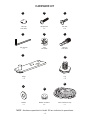
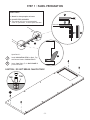
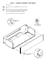
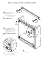
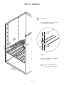
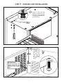
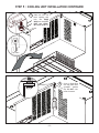
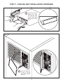
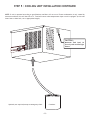
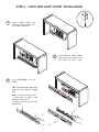
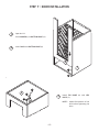
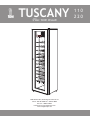
TUSCANY
Plus
WINE CELLAR
ASSEMBLY & OPERATION
MANUAL
~1~
110
220
~2~
READ BEFORE YOU START
1. LOCATING YOUR WINE CELLAR - Remember, it is not only an appliance but also a piece of furniture
A.
Provide 4” minimum clearance for both sides and back, keep the top completely clear.
Under no circumstances should the unit be “built-in” in any way.
B.
Never locate your wine cellar outdoors or in an area with extremes of temperature and
humidity.
Garages, attics, unfinished basements, laundry rooms, breezeways, closets or any
unventilated room. In other words these units must be installed in air-conditioned
environments which do not “trap” the warm air being exhausted.
C.
Temperatures in surrounding area must not exceed 80 °F (25 °C) with humidity levels not
to exceed 70% R.H. (Relative Humidity). Never set your temperatures below default (57ºF)
whenever ambient conditions are warm (above 75ºF) or humid (above 50%R.H.).
D.
Outlet power must be a DEDICATED separately fused, grounded, 15 Amp 110 - 120 V line.
E.
You must monitor your unit DAILY. If unit is in “Alarm”, unplug the unit immediately. Always
check for any water (condensate) leaks.
Vintage Keeper will not be liable or responsible for incidental or consequential damages.
(See Warranty).
F.
Place unit in a clean area and allow access to the exterior surfaces for periodic vacuuming
of the condensor coil. (See troubleshooting for details.)
G.
Always remove all bottles before relocating your wine cellar.
H.
Keep Instruction Manual for reference (Download manuals at www.koolspace.com if lost).
2. AREA FOR ASSEMBLING YOUR WINE CELLAR
Choose a clear 12’ by 12’ area with a level floor and carpenting to help reduce scratching of surfaces.
3. TOOLS
*
*
*
*
*
Hex wrench (included)
#2 Phillips screwdriver
#3 Phillips screwdriver or 1/4” Flat Screwdriver
Carpenter’s level
Helper or two is strongly recommended
4. TEST THE COOLING UNIT
Plug it in for a few minutes on a table top, to verify that controls and display are functional, and that
the unit is producing cool air after a few minutes of operation.
Note that the electronic controller has a one-minute cautionary delay between initial plug-in and
start-up of the compressor.
~3~
HARDWARE KIT
A
Cam Cap
x 20 (x24)*
D
Hex wrench
x1
B
C
Phillips Bolt
x2
Hex bolt
x 14
E
F
Cam
x 20 (x24)*
Cam Pin
x 20 (x24)*
G
H
Hinge
x2
Leg
x4
K
I
J
Washer
x1
Rubber Grommet
x2
Panel Insulation Strip
x1
*NOTE : Hardware quantities for Model 220 are indicated in parenthesis.
~4~
STEP 1 : PANEL PREPARATION
CAUTION :
K
1. Watch for sharp staples on boxes.
2. DO NOT STEP ON PANELS
3. The manual will give a recommended
order to open boxes, it saves space and time.
PANEL EDGE
K
K
Open Box V1.
1
Install INSULATION STRIP to Back, Top,
and Bottom Panels. PUSH IN FULLY!
2
Insert Cam Pins (F) in BACK PANEL’S
pre drilled holes.
K
CAUTION : DO NOT BREAK CAM PIN TABS!
TAB
TAB
BACK PANEL
F
~5~
STEP 2 : CABINET ASSEMBLY
1
Attach Top and Bottom to Back by CAREFULLY
aligning edge holes over Cam Pins and gently push
together to avoid damaging cam pins. DO NOT
BANG OR SLAP PANELS TOGETHER!!!
2
Insert Cam and make sure Arrow points to outside
edge.
Gently push down to bring panels together before
you tighten the Cam.
Cam Arrow faces away from outside edge when
tightened.
2
1
Use #3 philips or 1/4”
Flat head screwdriver
2
EDGE
PANEL EDGE
CAM in LOCKED
POSITION
~6~
STEP 2 : CABINET ASSEMBLY CONTINUED
Open Box V5 or V2.
1
2
Insert Cam Pins (F) into SIDE PANEL’S pre drilled holes both
sides.
Attach SIDES to Back/Bottom/Top by Carefully aligning edge
holes over Cam Pins and gently push together to avoid damaging
cam pins. DO NOT BANG OR SLAP PANELS TOGETHER!!!
Insert Cam, Push Panels together before tightening Cam.
TOP !!!
F
TOP PANEL
can be identified by
two Threaded Holes
A
3
~7~
Insert Cam Cap (A) in
all Cam Holes.
ED
GE
STEP 3 : HINGE,BASE AND LEGS INSTALLATION
2
1
H
Fasten one HINGE (G) to the
SIDE of the cabinet
NOTE : Hinge can be on either
side of the cabinet.
2
Install four LEGS (H)
into BASES fully in.
2
H
3
FR
ON
TB
AS
E
3
4
Fasten FRONT BASE
to
the BOTTOM of the cabinet
(FRONT BASE has to be set
with end tabs away from front
edge)
C
CA
BO B I N
TT E T
OM
Fasten BASE with HEX BOLTS (C)
4
3
G
D
1
T
ON
FR
E
G
ED
5
5
BASE TAB
NOTE: Fasten base with base tab away from the
front edge, then fasten and adjust the hinge
before fully tightening HEX BOLTS (C)
~8~
Raise cabinet and adjust the level by
turning (counter clockwise) the LEGS (H) as
needed.
STEP 4 : SHELVES
1
Open box V4
Hook SHELVES into hangers starting
from the bottom of cabinet
PRESS
1
TOP
1
2
BOTTOM
HINT :
CA
BO B I N
TT E T
OM
~9~
1
Snap SHELVES into hangers
on one side
2
Push the SHELVES down to
snap into opposite side hangers
STEP 5 : COOLING UNIT INSTALLATION
1
Screw in Bolt (B) and
Rubber Grommet (J) into
top panel until grommet
touches top. DO NOT compress Grommet.
LEFT SIDE ONLY!
J
B
K
O
PH
OO
B
E
N
2
J
ATTENTION!!!
SERIAL NUMBER
PLEASE WRITE DOWN THE
SERIAL NUMBER ON THE
WARRANTY REGISTRATION
FORM.
B
~10~
Insert Rubber
Grommet (J)
in RIGHT TAB
HOLE of cooling unit and
insert Bolt (B)
into
Rubber
Grommet as
shown:
STEP 5 : COOLING UNIT INSTALLATION CONTINUED
3
Slide unit into the
back opening and
lock the HOOK
WING over the LEFT
BOLT and GROMMET from (STEP 1).
Top View
OK
O
EB
N
O
PH
4
~11~
Screw in Right Bolt
into top panel until
grommet
touches
top. DO NOT compress Grommet.
STEP 5 : COOLING UNIT INSTALLATION CONTINUED
5
6
Insert Drain Cup by
angling the Drain
Cup inserting back
tab first then push
in front lip to allow
tab in.
Insert Air Deflector
to back of cooling
unit. Install bottom
Tab first.
~12~
STEP 5 : COOLING UNIT INSTALLATION CONTINUED
NOTE: If unit is operated according to specifications overflows will not occur. Excess condensation is only caused by
extreme conditions. Unit will shut off at 72 °F and will restart when temperature drops or unit is repluged. (In this case
insert hose to drain hole, cut to appropriate length.)
CAUTION :
Maximum Total Load: 1A
Use only with certified light
fixture.
Container
Optional (not required) except as emergency drain.
~13~
STEP 6 : LIGHT AND LIGHT COVER INSTALLATION
1
Fasten LIGHT CLIPS into
mounting holes predrilled on
front edge of TOP panel
4
5
Snap LIGHT in LIGHT CLIPS
Plug small end of power cord
into socket on side of light
Snap LIGHTCOVER over the
LIGHT
HINT: To hide excess light cord,
tuck into top space of cooling
unit.
NOTE : To replace the light bulb:
1. Press down on ends of light
behind to release cover.
2. Remove cover as light ends are
pushed down
ON
OF
1
~14~
F
2
STEP 7 : DOOR INSTALLATION
1
Open box V3
Place WASHER (I) on BOTTOM HINGE (G)
2
Insert DOOR onto BOTTOM HINGE (G)
2
I
1
G
D
3
C
3
G
Install TOP HINGE (G) with HEX
BOLTS (C)
NOTE :
~15~
Adjust final position of the
door before tightening the
bolts
CONTROLS :
FEATURES:
-
OPERATION:
PLUG IT IN
(wait one minute)
and ENJOY!
Default SET temperature 57º F/14º C (ideal for wine storage).
DISPLAY:
Calibration option of the temperature sensor.
SET temperature range 52ºF-72ºF.
Digital temperature sensor.
Dual display Fº/Cº.
Magnetic overflow sensor.
Settings are stored in memory for power failures.
Pre programed software will reach the quietest most efficient operation.
KEYS
57
- The display will show the detected temperature until the temperature will fall within 3º of the SET POINT.
- If the temperature is above the default 57º F + 1º or other preset value, after a delay of 1 minute the fan will
start, followed by the compressor within the next minute.
- The unit will cycle ON/OFF based on the temperature reading. Fan speeds are automatically set by the controller
to achieve optimum performance.
- Minimum ON and OFF cycle times are imposed by software, to prevent "short cycling".
CONTROLLER
OPERATION
TO MODIFY THE SET
TEMPERATURE
(range is 52-72ºF):
ACTION
DISPLAY EXAMPLE
BEFORE
57º
PRESS and RELEASE
AFTER
57º
To increase:
PRESS
once per degree
57º
58º
To decrease:
PRESS
once per degree
57º
56º
57º
14º
57º
57º
The new value will be memorized and the controller will reset automatically.
TO CHANGE FROM
ºF to ºC or ºC to ºF:
PRESS and HOLD
TO CALIBRATE:
HOLD DOWN
until buzzer sounds in 5 seconds
The new value will be memorized and the controller will reset automatically.
KEY, PRESS
and RELEASE BOTH.
Wait 5 seconds
57º
F0
USE
F0
F1
F0
-1
or
for each degree of offset
NOTE: A negative offset
will result in a warmer cabinet and a positive offset
will result in a cooler cabinet.
The new value will be memorized and the controller will reset automatically.
SAFETY FEATURES:
ALARM:
- If the temperature exceeds 72º F the unit will shut down, a sound warning will start and the dispaly will blink
alternating with the temperature reading.
- This function is disabled in the first 4 hours “ Cool Down” period or after any reset for another 4 hours.
- The unit will restart and continue the cooling and cycling if the temperature falls below 72º F.
TO RESET:
- Unplug and re plug the unit.
AL
OVERFLOW: - If the condensate pan is filled due to excessive humidity the unit stops, and warns with an acoustic signal and the
"CUP FULL" message on the display.
TO RESET: Empty cup located under the cooling unit.
~16~
MAXIMUM CAPACITIES AND LOADING TIPS
Maximum capacities and sample loading arrangements for Vintage Keeper Tuscany wine cellars
are illustrated below. Note the variations in shelf height, to accommodate the widest variety of
bottle types and sizes. Standard Burgundy and Bordeaux bottles are best arranged with necks
facing out; some taller bottles may need to be arranged neck to neck. Never stack bottles more
than two rows high on a shelf; all shelves must be installed as directed. Avoid placing bottles
directly in front of the cooling unit’s circulating fan for more uniform temperature in cabinet.
MODEL 110
13
Max 4" dia.
bottles
MODEL 220
WARNING*
7
Max 3.5" dia.
bottles
3 rows 3" dia.
or
2 rows 4.5" dia.
26
Max 4" dia.
bottles
14
7
14
7
14
7
14
7
14
7
7
Max 3.5" dia.
bottles
14
14
7
14
7
14
7
14
7
14
20
WARNING*
3 rows 3" dia.
or
2 rows 4.5" dia.
40
Max: 220 3" bottles
Max: 110 3" bottles
*WARNING:
Bottles in black will be in the cold air stream and could block airflow efficiency in some
circumstances (warm or humid areas). This area of the cabinet should have the coldest
temperature and may be used as your “chilling” section.
~17~
TROUBLE SHOOTING GUIDE
Although each Vintage Keeper cooling unit has been carefully tested at every stage of manufacture, occasional problems
arise, the majority of which are due to rough or careless handling during shipping or installation. Other problems may
derive from improper cabinet assembly, power interruption or surge, low line voltage (less than 105V), or failure to
clean the unit regularly (see illustration below). The following may help you determine what the problem may be; what
steps you can take to correct it, and what further steps may be required. Additional Trouble-Shooting information and
downloadable documents are available in the “Support” area of our web site: www.koolspace.com
Cleaning the coil
Coil is located at the top of
back panel.
Vacuum it periodically
IMPORTANT NOTE:
In order to provide maximum protection for your valuable wine collection, the following steps are highly advisable.
First and foremost, have your wine collection adequately insured. Second, install a battery-powered heat-sensitive alarm
to warn of any loss of cooling due to power interruption. Third, monitor your storage and ambient conditions on a regular,
daily basis. Fourth, install a high quality surge suppressor to protect against sudden power fluctuations. Fifth, clean the
unit as directed, on a regular basis, every 3 to 4 months vacuum the cooling unit coils (check our website for more info).
Sixth make sure to check water level in the DRAIN CUP periodically and empty. Be advised, also, that Drobot-Vintage
Keeper cannot in any event be liable or responsible for incidental or consequential damages.
IF:
CHECK:
THEN:
- Is the unit plugged in?
- Note that the unit has a 1-minute cautionary delay
between plugging in and full start-up; this is a built-in
COOLING UNIT - Is the power supply operational? safeguard to protect the compressor in the event of
DOES NOT RUN
sudden power failure
AT ALL WHEN - Is the LED display functional and are - Note that the power supply must be a dedicated,
PLUGGED IN
fans running?
separately-fused and grounded 15 Amp, 120V line. If an
extension cord must be used, it must be rated for 15
- Is there any evidence of shipping Amps. Do not share the outlet with other appliances.
damage on the cooling unit or
Unplug Unit, remove controller, check replaceable fuse
packaging materials?
(0.5A SLOW BLOW, 250V, 5X20mm) in the controller.
- If the unit is receiving power yet fans or compressor fail
to run, unplug for ten minutes, then try again
COOLING UNIT - Is the storage temp properly
RUNS BUT DOES set?
NOT COOL
SUFFICIENTLY
- Is the cabinet properly
assembled, with all joints air
tight?
- Note that the unit may take a few days to achieve the
desired storage temperature, even in a properly located,
airtight cabinet
- Take steps to reduce ambient temperatures and
compensate for additional heat gain if any cabinet walls
receive direct sunlight
- If gaps are visible at any panel joints, ensure that you
- Is the door properly adjusted to
have tightened all cams in all panels, to ensure
seal tightly when closed?
an airtight seal as detailed in our instructions
- Take steps to improve circulation of air to and from the unit
- Is airflow to and from the
- Adjust the door, if necessary, to seal tightly by
cooling unit unobstructed?
re-positioning the upper hinge and improving the cabinet
level
- Is the ambient air temperature
- Install the air deflector as directed
within the specified range?
- Increase your SET TEMPERATURE
- Clean the fan and grille areas
- Are any exterior surfaces of the
- If the problem persists, go to our website at
cabinet exposed to sunlight?
www.vintagekeeper.com and perform the “cooling unit
diagnostic” in the support section.
~18~
LIMITED WARRANTY AND PRODUCT SUPPORT
ONE YEAR LIMITED WARRANTY
If your Vintage Keeper cooling unit or cabinet fails to perform as designed within one year of the date of purchase, VINTAGE KEEPER
INC. warrants that, upon your request, it will be repaired or replaced, at our option, during the one year warranty period. This
warranty applies only to the first end-user purchaser of a Vintage Keeper unit that is purchased and used in the continental United
States or Canada (excludes Alaska and Hawaii). It is not valid for subsequent purchasers, nor for units in use outside North America.
The warranty period for your Vintage Keeper unit commences on the date you purchased it and expires one year thereafter.
PROOF OF PURCHASE
Within 10 days of purchase, complete and mail, fax or e-mail the registration sheet to VINTAGE KEEPER INC. Alternately, you may
register your warranty on our Internet web site, www.vintagekeeper.com. When you make a warranty claim, you must forward a copy
of your original dated bill of sale to establish your date of purchase.
IF YOU HAVE A PROBLEM WITH YOUR UNIT
Customer service and warranty problems are handled online at www.vintagekeeper.com. You will find a comprehensive welldocumented and easy-to-use solution to almost any question or problem you may have. The inquiry forms are filled in on-line and
connect you to our representatives who will process your requests for warranty service. This is the quickest way to solve your
problems. If you do not have access to the internet you may call us from 9:00 a.m to 4:00 p.m EST, to request a WARRANTY CLAIM
INFORMATION KIT. We can fax or mail it to you. You can fill in the enclosed REQUEST FOR RETURN AUTHORIZATION CODE form and
return it by mail or fax. We can then promptly process your claim.
REPLACEMENT ?
At our option we may choose to offer you a replacement part or product rather than a repair. Upon your authorization to accept a
replacement unit and with appropriate security (credit card authorization), we will promptly ship a replacement unit. The replacement
may be a unit that has been reconditioned by VINTAGE KEEPER INC. The unit that needs service must be packed and returned to us,
shipping prepaid. Upon its receipt, we will release your credit card security. Go online to the SUPPORT section on our web site at
www.vintagekeeper.com to request warranty service.
REPAIR ?
If we determine that your unit needs to be repaired rather than replaced we will issue you a Return Authorization Code. Go online
to the SUPPORT section of our web site at www.vintagekeeper.com to request warranty repair service. Please save the original
packaging materials to facilitate shipment. Mark the Return Authorization Code clearly on the outside of the package, enclose a brief
note describing the problem and send the unit, shipping prepaid, to VINTAGE KEEPER INC.
WHAT MUST YOU DO?
Your unit is designed to perform with a minimum amount of user maintenance when installed and operated precisely as directed
in the manual. You are, however, responsible for the required user maintenance described in the manual, specifically, regular
cleaning of the condensor coil and fans. Also, you must take steps to protect the unit from sudden power surges. As with any sensitive
electronic device, your Vintage Keeper unit may be damaged by power surges or spikes, including lightning strikes, acts of god, sudden
interruptions or prolonged low-voltage conditions, which are not covered by this Warranty. You must monitor your unit’s performance
on a daily basis. If there is an apparent problem or “Alarm” condition, you must disconnect the power supply to avoid potential
damage to your wine collection. It is your responsibility to insure your wine, and to take all reasonable and necessary precautions to
safeguard its condition.
WHAT THE WARRANTY DOES NOT COVER
This warranty covers only defects in materials and workmanship provided by VINTAGE KEEPER INC. and does not cover equipment
damage or malfunction from misuse, abuse, accident, act of God, or any unauthorized alteration or modification. The product must
have been installed and operated precisely as directed in the manual which acompanies each product. Improper return shipping,
inadequate packaging or shipping damage is not covered unless the unit is packaged and shipped in accordance with Vintage Keeper
replacement procedures. This product is not warranted for COMMERCIAL USE. Such usage will void any warranty. Third party servicing
of this product during the warranty period will also void the warranty, as will any evidence of tampering or alteration to the serial
number and or the original dated bill of sale.
REPLACEMENT AND REPAIR ARE YOUR ONLY REMEDIES
YOUR ONLY REMEDY UNDER THIS WARRANTY IS THE REPLACEMENT OR REPAIR OF YOUR ELIGIBLE PRODUCT AS DESCRIBED ABOVE. NEITHER
THIS WARRANTY NOR ANY OTHER WARRANTY, EXPRESS OR IMPLIED, INCLUDING, BUT NOT LIMITED TO, THE IMPLIED WARRANTIES OF
MERCHANTABILITY AND FITNESS FOR A PARTICULAR PURPOSE, SHALL EXTEND BEYOND THE ONE-YEAR WARRANTY PERIOD. UNDER NO
CIRCUMSTANCES SHALL VINTAGE KEEPER INC. BE LIABLE FOR ANY SPECIAL INCIDENTAL, INDIRECT OR PUNITIVE DAMAGES OR FOR ANY
CONSEQUENTIAL DAMAGES, INCLUDING SPOILAGE OF WINE, EVEN IF VINTAGE KEEPER INC. KNOWS OR IS INFORMED THAT SUCH DAMAGES
ARE POSSIBLE. IT IS YOUR RESPONSIBILITY TO INSURE YOUR WINE, AND TAKE ALL REASONABLE, NECESSARY PRECAUTIONS TO SAFEGUARD
ITS CONDITION. SOME STATES DO NOT ALLOW THE EXCLUSION OR LIMITATION OF INCIDENTAL OR CONSEQUENTIAL DAMAGES, SO THE
ABOVE EXCLUSION OR LIMITATION MAY NOT APPLY TO YOU. NO RESELLER IS AUTHORIZED TO MODIFY THE TERMS OF THIS WARRANTY. ANY
ADDITIONAL WARRANTY OFFERED BY A RESELLER IS THE SOLE RESPONSIBILITY OF THAT RESELLER.
SERVICE AFTER YOUR WARRANTY EXPIRES
If your unit requires service after the one-year warranty period expires, you may have it serviced locally by any qualified HVAC
technician, or you may purchase a new unit at a special discount under our Extended Warranty Program. Please be ready to provide
model, serial number, credit card number and a copy of your original dated bill of sale. In addition, repair service is always available
direct from us at flat rates below the prevailing charges for local service. However, using our Extended Warranty Program for units
under 5 years old will always be a preferable solution to returning a unit for repair. Go online at www.vintagekeeper.com to request
Repair Service or see our Extended Warranty Program.
~19~
TUSCANY
Plus
WINE CELLAR
5648 McAdam Rd., Mississauga ON CAN L4Z 1T2
Phone : 905.501.8582 Fax : 905.501.0889
Toll free: 1.888.274.8813
[email protected]
www.vintagekeeper.com
~20~
110
220