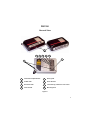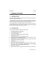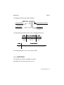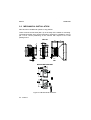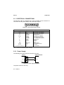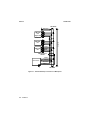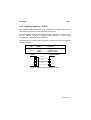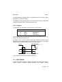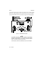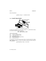
1
Wichtiger Hinweis
Im Handbuch unter Pkt. 1.2 – Description- ist vermerkt, das der DS1100 mit einer
Betriebsspannung von 5V DC betrieben werden darf.
Soll einen höhere Spannung, z.B. von einer SPS verwendet werden, dann ist ein
DC/DC Konverter notwendig, der zwischen Anschlussbox und Scanner gesetzt wird.
Darüber hinaus ist auch eine DS1100 Version mit dem Kürzel : SH 2347 hinter der
Versions-Nummer verfügbar.
Diese ist direkt zwischen 10 – 30 V DC z.B. an einer SPS betreibbar.
Beachten Sie daher das Typenschild des Scanners vor dem Einbau.
Ohne diese SH-Nummer wird der Scanner nach Anlegen einer
Betriebsspannung > 5V DC zerstört !!
Gerd Schroedter
Tel: 0521-93270-55
E-Mail: [email protected]
Seite 1 von 1
Datei: DS1100_warnung
Stand: A
Datum: 02/2004
DS1100
INSTALLATION MANUAL
We
Datalogic S.p.A.
Via Candini, 2
40012 - Lippo di Calderara
Bologna - Italy
declare under our sole responsibility that the product(s)
DS1100-XXXX, Laser Scanner and all its models
to which this declaration relates is in conformity with the following standard(s) or other
normative document(s)
EN 55022, August 1994:
LIMITS AND METHODS OF MEASUREMENTS OF RADIO DISTURBANCE
CHARACTERISTICS OF INFORMATION TECHNOLOGY EQUIPMENT (ITE)
EN 50082-2, March 1995:
ELECTROMAGNETIC COMPATIBILITY. GENERIC IMMUNITY STANDARD.
PART 2: INDUSTRIAL ENVIRONMENT
Following the provision of the Directive(s):
89/336 CEE AND SUCCESSIVE AMENDMENTS, 92/31 CEE; 93/68 CEE
Ruggero Cacioppo
Lippo di Calderara, 12/07/1999
Quality Assurance Supervisor
Product names mentioned herein are for identification purposes only and may be trademarks
and or registered trademarks of their respective companies.
Datalogic reserves the right to make modifications and improvements without prior notification.
© - 1999 Datalogic S.p.A.
821000380
CONTENTS
GUIDE TO INSTALLATION .............................................................. iv
General View ......................................................................................v
SAFETY PRECAUTIONS ................................................................. vi
Laser Safety....................................................................................... vi
1
1.1
1.2
1.2.1
1.3
1.4
GENERAL FEATURES ...................................................................1.1
Introduction ......................................................................................1.1
Description.......................................................................................1.1
Indicators .........................................................................................1.2
Available Models..............................................................................1.2
Accessory ........................................................................................1.3
2
2.1
2.2
2.2.1
2.3
2.3.1
2.3.2
2.3.3
2.3.4
2.3.5
2.4
2.5
2.5.1
2.5.2
2.5.3
INSTALLATION ..............................................................................2.1
Package Contents ...........................................................................2.1
Mechanical Installation ....................................................................2.2
Reading Position..............................................................................2.3
Electrical Connections .....................................................................2.4
Power Supply...................................................................................2.4
Main Serial Interface - RS485 Half-Duplex......................................2.5
Auxiliary Interface - RS232 ..............................................................2.7
Inputs ...............................................................................................2.8
Outputs ............................................................................................2.9
Positioning .......................................................................................2.9
Typical Layouts ..............................................................................2.11
Point-to-Point .................................................................................2.11
RS485 Master/Slave......................................................................2.11
Multiplexer .....................................................................................2.13
3
3.1
3.2
3.3
3.3.1
3.4
READING FEATURES ....................................................................3.1
Step-Ladder Mode ...........................................................................3.1
Picket-Fence Mode..........................................................................3.2
Performance ....................................................................................3.3
Raster ..............................................................................................3.3
Reading Diagrams ...........................................................................3.4
4
4.1
MAINTENANCE ..............................................................................4.1
Cleaning...........................................................................................4.1
5
TECHNICAL FEATURES................................................................5.1
iii
GUIDE TO INSTALLATION
The following can be used as a checklist to verify all of the steps necessary
for complete installation of the DS1100 scanner.
1) Read all information in the section "Safety Precautions” at the beginning
of this manual.
2) Correctly position and mount the scanner for barcode reading according
to the information in par. 2.2, 2.4 and 3.4.
3) Provide correct system cabling according to the signals necessary for
your application (see all sub-paragraphs under 2.3). See also subparagraphs under 2.5 for reference.
4) Install the Configuration Disk.
Upon successful completion of the installation, the readme.hlp file is
opened, giving details about how to get started configuring your scanner.
See also the Guide To Rapid Configuration link.
Specific parameter details are available in the Help On Line.
NOTE
Fine tuning of the scanner position for
barcode reading can be accomplished using
the Test Mode as described in WinHost.
The installation is now complete.
iv
DS1100
General View
1
2
3
4
5
6
7
8
1
Laser Beam Output Window
5
Ext Trig LED
2
TX Data LED
6
Power ON LED
3
Good Read LED
7
Laser Warning and Device Class Label
4
Laser ON LED
8
Mounting Holes
Figure A
v
SAFETY PRECAUTIONS
LASER SAFETY
The following information is provided to comply with the rules imposed by
international authorities and refers to the correct use of the DS1100 scanner.
Standard Regulations
This scanner utilizes a low-power laser diode. Although staring directly at the
laser beam momentarily causes no known biological damage, avoid staring
at the beam as one would with any very strong light source, such as the sun.
Avoid that the laser beam hits the eye of an observer, even through reflective
surfaces such as mirrors, etc.
This product conforms to the applicable requirements of both IEC 825-1 and
CDRH 21 CFR 1040 at the date of manufacture. The scanner is classified as
a Class 2 laser product according to IEC 825-1 regulations and as a Class II
laser product according to CDRH regulations.
There is a safety device which allows the laser to be switched on only if the
motor is rotating above the threshold for its correct scanning speed.
The laser beam can be switched off through a software command (see also
«Beam Shutter» in the WinHost Help On Line).
WARNING
Use of controls or adjustments or performance of
procedures other than those specified herein may
result in exposure to hazardous visible laser light.
The laser light is visible to the human eye and is emitted from the window on
the front of the scanner (Figure A, 1 ).
vi
The warning label indicating exposure to laser light and the device
classification is applied onto the body of the scanner (Figure A, 7 ).
Warning and device class label
For installation, use and maintenance it is not necessary to open the
scanner.
The laser diode used in this device is classified as a class 3B laser product
according to IEC 825-1 regulations and as a Class IIIb laser product
according to CDRH regulations. As it is not possible to apply a classification
label on the laser diode used in this device, the following label is reproduced
here:
LASER LIGHT
AVOID EXPOSURE TO BEAM
CLASS 3B LASER PRODUCT
MAX. OUTPUT RADIATION 7 mW
EMITTED WAVE LENGTH 630~680 nm
TO IEC 825-1 (1993)
Laser diode class label
Any violation of the optic parts in particular can cause radiation up to the
maximum level of the laser diode (7 mW at 630 to 680 nm).
vii
This page is intentionally left blank.
viii
DATALOGIC
DS1100
1 GENERAL FEATURES
1.1 INTRODUCTION
The DS1100 scanner with decoder offers the best cost-effective solution for
demanding industrial applications.
The DS1100 ultra compact dimensions, based on Datalogic's experience in
miniaturised laser components, have been specifically designed to make the
scanner's integration into automated equipment extremely easy.
The Windows-based user-friendly WinHost utility program provided on
diskette simplifies the scanner’s setup. The DS1100 can also be configured
from a Host PC through the Host Mode procedure.
1.2 DESCRIPTION
Some of the main features of DS1100 are listed below:
•
•
•
•
•
•
•
•
•
•
•
•
•
miniaturised dimensions, light weight.
scanning speed: 350 scans/sec.
raster version available.
2 serial communication interfaces: RS232 + RS485.
reads all popular codes.
supply voltage: 5 Vdc ( 4 to 30 Vdc with converter).
test mode to verify the reading features and exact positioning of the
scanner without the need for external tools.
programmable in 4 different operating modes to suit the most various
barcode reading system requirements.
code verifier.
programmable input and output signals.
light source: visible laser diode; the light emitted has a wave length of
630 ∼ 680 nm. For laser safety precautions refer to the “Safety
Precautions” section at the beginning of this manual.
low power consumption.
IP65 protection class of the enclosure; the reader is therefore suitable for
General Features - 1.1
DS1100
DATALOGIC
industrial environments where high protection against harsh external
conditions is required.
The laser beam output window is on the side of the scanner in DS1100XXX0 models and on the upper part of the scanner in DS1100-XXX1
models, (Figure A, ).
A security system allows the laser to activate only once the motor has
reached the correct rotational speed; consequently, the laser beam is
generated after a slight delay from the power on of the scanner.
1.2.1 Indicators
The five LEDs on the scanner indicate the following:
POWER ON
GOOD READ
EXT TRIG
TX DATA
LASER ON
(red) indicates the reader is connected to the power supply.
(Figure A, ).
(red) is used to signal the possibility of a successful barcode
reading. (Figure A, ).
(yellow) indicates external trigger activity. Refer to par.
2.3.4. (Figure A, ).
(green). When blinking, it indicates data transmission.
(Figure A, ).
(green) indicates laser ON state. (Figure A,
).
The screw holes on the body of the reader are for mechanical fixture (Figure
A, ).
1.3 AVAILABLE MODELS
The DS1100 scanner is available in versions that differ in regard to the
following parameters:
• Resolution.
• Reading window position.
• Linear or raster models.
1.2 - General Features
DATALOGIC
DS1100
The following models are therefore available:
DS1100 - X X X X
Optical Resolution
Reading Window Position
1 = Standard Resolution
2 = High Resolution
0 = Direct
1 = 90°
Serial Interface
Linear/Raster
1 = RS232 + RS485
0 = Linear
1 = Raster
The following tables display each version’s reading performance.
mm (mils)
1XXX
2XXX
1XXX
2XXX
scans/s
0.20 (8)
0.12 (5)
350
350
30 mm (1.2 in) - 220 mm (8.7 in) on 0.50 mm (20 mils) codes
10 mm (0.4 in) - 110 mm (4.3 in) on 0.30 mm (12 mils) codes
See reading diagrams in par. 3.4 for further details.
1.4 ACCESSORY
The following accessory is available on request:
DC5-2200: DC converter 4-30 Vdc to 5 Vdc.
General Features - 1.3
DS1100
DATALOGIC
This page is intentionally left blank.
1.4 - General Features
DATALOGIC
DS1100
2 INSTALLATION
2.1 PACKAGE CONTENTS
Verify that the DS1100 reader and all the parts supplied with the equipment
are present and intact when opening the packaging; the list of parts includes:
1.
2.
3.
4.
5.
DS1100 reader with cable
Installation Manual
DS1100 configuration program disk
Bar code test chart (PCS = 0.9)
Mounting kit: - bracket
- screws
3
2
4
5
1
Figure 2.1 - DS1100 package contents
Installation - 2.1
DS1100
DATALOGIC
2.2 MECHANICAL INSTALLATION
DS1100 can be installed to operate in any position.
There are three screw holes (M3 x 5) on the body of the reader for mounting.
The diagram below gives all the information required for installation; refer to
par. 2.4 for correct positioning of the scanner with respect to the code
passage zone.
DS1100
4
0.16
50
1.97
15.4
0.61
B
7.7
0.3
4
0.16
6
0.24
mm
inch
MOUNTING BRACKET
Figure 2.2 - DS1100 overall dimensions
2.2 - Installation
A
61
2.4
80
3.15
64.3
2.53
M3 n°3
22.5
0.89
DATALOGIC
DS1100
2.2.1 Reading Position
In DS1100-XXX1 models the laser beam is emitted from the output window
with a 12° (± 2) skew angle.
This allows installation with minimum overall dimensions.
DS1100-XXX1
90° Reading
Window Position
Laser
Beam
12° ± 2
Laser
Beam
DS1100-XXX0
Direct Reading
Window Position
± 2°
Figure 2.3 - Reading position
Installation - 2.3
DS1100
DATALOGIC
2.3 ELECTRICAL CONNECTIONS
The DS1100 cable is equipped with a 25-pin female D-sub connector for
connection with the power supply and input/output signals:
Figure 2.4 – 25-pin female D-sub connector
25-pin D-sub connector pinout
Pin
9,13
25
1*
2, 21
3, 20
4
5
7
8
11
18
19
12, 22
23, 24
6, 10, 14, 15, 16, 17
Name
VS
GND
CHASSIS
TXAUX
RXAUX
RTX485RTX485+
SGND
OUT1 +
OUT2 +
IN1 EXT TRIGGND
N.U.
NC
Function
Power supply input voltage +
Power supply input voltage Chassis Ground
TX RS232 Aux. Interface
RX RS232 Aux. Interface
RTX- RS485 Main Interface
RTX+ RS485 Main Interface
Signal Ground
Output 1 +
Output 2 +
Input 1 External trigger Input/Output reference
Not Used
Not Connected
* Pins 1 and 25 are connected together internally.
2.3.1 Power Supply
The following pins of the DS1100 connector are used:
DS1100
USER INTERFACE
13/9
V+ (5 Vdc)
VS
25
GND
GND
CHASSIS
1
Figure 2.5 - Power supply connections
The power must be 5 Vdc only.
2.4 - Installation
DATALOGIC
DS1100
2.3.2 Main Serial Interface - RS485 Half-Duplex
The RS485 half-duplex interface (3 wires + shield) is used for polled
communication protocols.
It can be used for Multidrop connections in a master/slave layout or with a
Datalogic Multiplexer, (see par. 2.5.2 and 2.5.3) exploiting a proprietary
protocol based on polled mode called MUX32 protocol, where a master
device polls slave devices to collect data.
The connector pinout follows:
Pin
5
4
7
Name
RTX485+
RTX485 SGND
Function
RS485 + transmitted/received data
RS485 - transmitted/received data
Signal Ground
DS1100
USER INTERFACE
5
RTX485 +
4
RTX485 -
7
SGND
RS485 +
RS485 -
RS485 Ref
Figure 2.6 - RS485 half-duplex connections
For this interface type, the Multidrop Address must also be set via serial
channel by the WinHost utility or by ESC sequences.
Figure 2.7 shows an example of a multidrop configuration between a
Multiplexer and DS1100 scanners.
Installation - 2.5
DS1100
DATALOGIC
120 Ohm
max 2 m
DS1100
#x
(up to 31)
max 1200 m
DS1100
#1
RTX485 +
DS1100
#0
RTX485 SGND
Three wires +
shield
RTX485 +
RTX485 MULTIPLEXER
RS485 REF
SHIELD
120 Ohm
Figure 2.7 - DS1100 Multidrop connection to a Multiplexer
2.6 - Installation
DATALOGIC
DS1100
2.3.3 Auxiliary Interface - RS232
The auxiliary serial interface is used exclusively for RS232 point-to-point
connections. It is also used for configuring the DS1100.
The parameters relative to the auxiliary interface (baud rate, data bits, etc.)
can be defined using the Winhost utility program or "Host Mode
Programming", installed from the diskette.
The following pins of the 25-pin connector are used to connect the RS232
auxiliary interface:
Pin
Name
Function
3, 20
2, 21
7
RXAUX
TXAUX
SGND
Auxiliary input
Auxiliary output
Signal Ground
DS1100
USER INTERFACE
3/20
RXAUX
2/21
TXAUX
7
SGND
TXD
RXD
SGND
Figure 2.8 - RS232 auxiliary interface connections
Installation - 2.7
DS1100
DATALOGIC
2.3.4 Inputs
The inputs available on the connector supplied with the scanner are indicated
below:
Pin
Name
Function
18
19
22
IN1 EXT TRIGGND
Input 1 External trigger (input -)
I/O Reference
The EXT TRIG input is used to connect the external trigger which tells the
scanner to scan for a code. The active state of this input is selected in
software. Refer to the Winhost Help On Line.
The yellow LED (Figure A, ) is on when EXT TRIG- is shorted to GND.
This input is driven by an NPN type command. The connections are indicated
in the following diagram:
DS1100
+5V
USER INTERFACE
13/9
VS
V
47 K
19
EXT TRIG -
22
GND
Signal
Ground
Figure 2.9 - External Trigger Input command
The general purpose input IN1, in the Standard Application Program, can be
used to store the code verifier (see “Store Verifier Hw” in the WinHost Help
On Line).
DS1100
+5V
USER INTERFACE
13/9
VS
V
47 K
18
IN1 -
22
GND
Ground
Figure 2.10 - IN1- Input command
2.8 - Installation
DATALOGIC
DS1100
An anti-disturbance hardware filter is implemented on the External Trigger
input (about 1 millisecond delay).
An additional 15 ms (typical) delay can be implemented through a dedicated
software parameter (refer to WinHost Help On Line).
2.3.5 Outputs
The following pins are present on the connector of the scanner:
Pin
8
12
11
22
Name
OUT1+
GND
OUT2+
GND
Function
Output 1 +
I/O Reference
Output 2+
I/O Reference
The meaning of the two outputs OUT1 and OUT2 can be defined by the user.
Refer to the Winhost Help On Line.
By default, OUT1 is the No Read signal, which activates when the code
signalled by the external trigger is not decoded, and OUT2 is the Right
output, which activates when the code is correctly decoded.
DS1100
USER INTERFACE
Vext 50 Vdc max., 50 mA max.
8/11
OUT 1 + / OUT 2 +
12/22
GND
Ground
Figure 2.11 - DS1100 Output connections
These outputs are both level or pulse configurable.
2.4 POSITIONING
The DS1100 scanner is able to decode moving barcode labels at a variety of
angles, however significant angular distortion may degrade reading
Installation - 2.9
DS1100
DATALOGIC
performance. When mounting the DS1100 take into consideration these three
ideal label position angles: Pitch 0°, Skew 15° to 30° and Tilt 0°.
Follow the suggestions for the best orientation:
The Pitch angle is represented by
the value P in Figure 2.12.
Position the reader in order to
minimize the Pitch angle.
Figure 2.12 - Pitch Angle
The Skew angle is represented by
the value S in Figure 2.13. Position
the reader to assure about 15° for
the Skew angle. This avoids the
direct reflection of the laser light
emitted by the DS1100.
For the raster version, this angle
refers to the most inclined or external
raster line, so that all other raster
lines assure more than 15° Skew.
For the skew angle value with
DS1100 90° versions, refer to
par.2.2.1.
Figure 2.13 - Skew angle
The Tilt angle is represented by the
value T in Figure 2.14. Position the
reader in order to minimize the Tilt
angle.
Figure 2.14 - Tilt angle
2.10 - Installation
DATALOGIC
DS1100
2.5 TYPICAL LAYOUTS
2.5.1 Point-to-Point
In this layout data is transmitted to the Host on the RS232 Auxiliary serial
interface. The Local Echo communication mode must be enabled (default)
See the Winhost Help On Line.
When On-Line Operating mode is used, the scanner is activated by an
External Trigger (photoelectric sensor) when the object enters its reading
zone.
Figure 2.15 – Point to Point Layout
2.5.2 RS485 Master/Slave
The RS485 master/slave connection is used to collect data from several
scanners to build a multi-point or a multi-sided reading system; there can be
one master and up to 5 slaves connected together.
The Slave scanners are connected together using the RS485 half-duplex
main serial interface. Every slave scanner must have a multidrop address in
the range 0-4.
The master scanner is also connected to the Host on the RS232 auxiliary
serial interface.
For details, see the Guide To Rapid Configuration in the WinHost Help On
Line.
Installation - 2.11
DS1100
DATALOGIC
The External Trigger signal is unique to the system; there is a single reading
phase and a single message from the master scanner to the Host computer.
The main and auxiliary ports are connected as shown in the following figure.
Figure 2.16 – RS485 Master/slave layout
NOTE
The auxiliary serial port of the slave scanners can be used in
Local Echo communication mode to control any single scanner
(visualize collected data) or to configure it using the WinHost
utility or Host Mode programming procedure.
The termination resistors of the RS485 bus must not be installed.
2.12 - Installation
DATALOGIC
DS1100
2.5.3 Multiplexer
Each scanner is connected to a Multiplexer (for example MX4000) with the
RS485 half-duplex main interface.
31
1
0
MX4000
Figure 2.17 - Multiplexer layout
The auxiliary serial interface can be used in Local Echo mode to control any
single scanner (visualize collected data) or to configure it using the WinHost
utility or Host Mode programming procedure.
When On-Line Operating mode is used, the scanner is activated by an
External Trigger (photoelectric sensor) when the object enters its reading
zone.
Installation - 2.13
DS1100
DATALOGIC
This page is intentionally left blank.
2.14 - Installation
DATALOGIC
DS1100
3 READING FEATURES
The number of scans performed on the code by the DS1100 and therefore
the decoding capability is influenced by the following parameters:
• number of scans per second
• code motion speed
• label dimensions
• scan direction in respect to code motion
Typically, 5 scans should be allowed during the code passage to ensure a
successful read.
3.1 STEP-LADDER MODE
Code motion direction
at LS speed
Laser beam
Figure 3.1 - "Step-ladder" scanning mode
If scanning is perpendicular to the code motion direction (Figure 3.1 - "stepladder" mode), the number of effective scans performed by the reader is
given by the following formula:
SN = [(LH/LS) * SS] - 2
These symbols signify:
SN = number of effective scans
LH = label height (in mm)
LS = label movement speed (in mm/s)
SS = number of scans per second
For example, the DS1100 (350 scans/sec.) for a 25 mm high code moving at
Reading Features - 3.1
DS1100
DATALOGIC
500 mm/s performs:
[(25/500) * 350] - 2 = 15 effective scans.
3.2 PICKET-FENCE MODE
Code motion direction
at LS speed
Laser beam
Figure 3.2 - "Picket-fence" scanning mode
If scanning is parallel to the code motion, (Figure 3.2 - "picket-fence" mode),
the number of effective scans is given by:
SN = [((FW-LW)/LS) * SS] -2
These symbols signify:
SN
FW
LW
LS
SS
=
=
=
=
=
number of effective scans
reading field width (in mm)
label width (in mm)
label movement speed (in mm/s)
scans per second
For example, for a 50 mm wide code moving in a point where the reading
field is 180 mm wide at a 1300 mm/s speed, the DS1100 (350 scans per
sec.), performs:
[((180-50)/1300) * 350] - 2 = 33 scans
3.2 - Reading Features
DATALOGIC
DS1100
3.3 PERFORMANCE
The DS1100 scanner is available in different versions according to the
reading performance.
mm (mils)
1XXX
2XXX
1XXX
2XXX
scans/s
0.20 (8)
0.12 (5)
350
350
30 mm (1.2 in) - 220 mm (8.7 in) on 0.50 mm (20 mils) codes
10 mm (0.4 in) - 110 mm (4.3 in) on 0.30 mm (12 mils) codes
Refer to the diagrams given in par. 3.4 for further details on the reading
features. These diagrams are taken on various resolution sample codes at a
25 °C ambient temperature, depending on the conditions listed under each
diagram.
3.3.1 Raster
Raster versions are available. If standard devices do not satisfy specific
requirements, contact your nearest Datalogic distributor, supplying code
samples, to obtain complete information on the reading possibilities.
The max. capture of raster versions is 15 mm (0.6 in) at 220 mm (8.7 in).
Reading Features - 3.3
DS1100
DATALOGIC
3.4 READING DIAGRAMS
The following diagrams show the reading distance for barcodes with different
densities.
DS1100-1XXX Standard Resolution
0
20
40
60
80
100
120
140
160
180
200
220 mm
100
80
60
40
20
0.20 mm
(8 mils )
0
0.30 mm
(12 mils)
20
40
60
80
100
mm
NOTE
(0,0) is the center of the laser
beam output window.
CONDITIONS:
Code
PCS
"Pitch" angle
"Skew" angle
"Tilt" angle
=
=
=
=
=
Interleaved 2/5 or Code 39
0.90
0°
15°
0°
3.4 - Reading Features
0.50 mm,
(20 mils)
DATALOGIC
DS1100
DS1100-2XXX High Resolution
0
10
20
30
40
50
60
70
80
90
100
110 mm
60
50
40
30
0.20 mm
(8 mils )
20
0.30mm
(12 mils)
10
0.12 mm
(5 mils )
0
10
20
30
40
50
60
mm
NOTE
(0,0) is the center of the laser
beam output window.
CONDITIONS:
Code
PCS
"Pitch" angle
"Skew" angle
"Tilt" angle
=
=
=
=
=
Interleaved 2/5 or Code 39
0.90
0°
15°
0°
Reading Features - 3.5
DS1100
DATALOGIC
This page is intentionally left blank.
3.6 - Reading Features
DATALOGIC
DS1100
4 MAINTENANCE
4.1 CLEANING
Clean the windows periodically for continued correct operation of the reader.
Dust, dirt, etc. on the windows may alter the reading performance.
Repeat the operation frequently in particularly dirty environments.
Use soft material and alcohol to clean the windows and avoid any abrasive
substances.
WARNING
Clean the window of the DS1100 when the
scanner is turned off or, at least, when the
laser beam is deactivated.
Maintenance - 4.1
DS1100
DATALOGIC
This page is intentionally left blank.
4.2 - Maintenance
DATALOGIC
DS1100
5 TECHNICAL FEATURES
DS1100-1XXX
DS1100-2XXX
ELECTRICAL FEATURES
Maximum input voltage
Power consumption max.
5 Vdc ± 5%
1.5 W
INPUTS / OUTPUTS
Serial interfaces:
Main
Auxiliary
Baud Rates
Control Inputs
Outputs
VCE max.
Collector current max.
VCE saturation
Power dissipation max.
RS485 half-duplex
RS232
150 to 115200 baud
External Trigger; Aux. Input
User-defined OUT1 and OUT2
50 Vdc
50 mA continuous
0.3V at 10 mA max.
200 mW at 40 °C (Ambient temp.)
OPTICAL FEATURES
Light source
Wave length (Note 1)
Safety class
Semiconductor laser diode
630 ∼ 680 nm
Class 2 - IEC 825-1;
Class II - CDRH
READING FEATURES (Note 2)
Scan rate
Aperture angle
Max. Reading distance
Maximum resolution
350 scans/sec
70°
220 mm, (8.7 in)
110 mm (4.3 in)
0.20 mm (8 mils)
0.12 mm (5 mils)
USER INTERFACE
LED indicators
Power ON,
Good Read,
Ext Trig,
TX Data,
Laser ON
Technical Features - 5.1
DS1100
DATALOGIC
SOFTWARE FEATURES
READABLE CODE SYMBOLOGIES
• EAN/UPC (including Add-on 2 and Add-on 5)
• Code 93
• 2/5 Interleaved
• Code 128
• Code 39 (Standard and Full ASCII)
• EAN 128
• Codabar
• Pharmacode
Other symbologies available on request.
up to six different codes during one reading phase
CODE SELECTION
DECODING SAFETY
can enable multiple good reads of same code
HEADERS AND TERMINATORS
up to four headers and four terminators
OPERATING MODES
On-Line, Automatic, Serial-On-Line, Test
CONFIGURATION MODES
• through menus using WinHost utility
• receiving commands from one of the serial ports
(HOST MODE)
Non-volatile internal EEPROM
PARAMETER STORAGE
ENVIRONMENTAL FEATURES
Operating temperature (Note 3)
0 to 45 °C (32 to 113 °F)
Storage temperature
-20 to 70 °C (-4 to 158 °F)
90% non condensing
IEC 68-2-6 test FC 1.5 mm;
10 to 55 Hz; 2 hours on each axis
IEC 68-2-27 test EA 30G;
11 ms; 3 shocks on each axis
IP65
Humidity max.
Vibration resistance
Shock resistance
Protection class
PHYSICAL FEATURES
Mechanical dimensions
Weight without cable
80 x 50 x 22 mm (3.15 x 1.97 x 0.89 in.)
<100 g. (<3.53 oz.)
Note 1:
The features given are typical at a 25 °C ambient temperature (if not otherwise
indicated).
Note 2:
Further details given in par. 3.3 and 3.4.
Note 3:
If the reader is used for a long period of time in high temperature environments
(over 40 °C), use of the Beam Shutter is advised (see the Winhost configuration
program).
5.2 - Technical Features