1
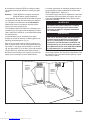
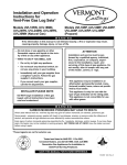
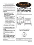
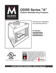
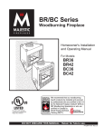
Installation and Operation Instructions for
Vent-Free Gas Log Sets*
Models: VL18, VL21 and VL24 (Natural Gas)
VL18LP, VL21LP and VL24LP (Propane)
DE S I GN
C E RT I F I E D
CE
Decorative Gas Appliances for
Installation inSolid-Fuel Burning Fireplaces.
RTIFI E D
Tested and listed to
ANSI Z21.11.2b-2004, Unvented Heaters, and
Z21.60b-2004; CGA 2.26b-2004
WARNING
If the information in this manual is not followed exactly, a fire or explosion may result, causing property
damage, injury, or loss of life.
— Do not store or use gasoline or other flammable vapors and liquids in the vicinity of this or
any other appliance.
— WHAT TO DO IF YOU SMELL GAS
• Do not try to light any appliance.
• Do not touch any electrical switch; do not
ATTENTION
Installation and service must be performed by
a qualified agency, individual, firm, corporation, or company, experienced in the installation, repair, and servicing of this type of gas
appliance. Do not modify, alter or tamper with
any part of this heater, control, or logs.
use any phone in your building.
• Immediately call your gas supplier from a
neighbor’s phone. Follow the gas supplier’s instructions.
• If you cannot reach your gas supplier, call
the fire department.
INSTALLER PLEASE NOTE:
DO NOT begin installation of this gas logset
until all instructions have been read and
understood.
This appliance may be installed in an aftermarket, permanently located, manufactured
(mobile) home, where not prohibited by local
codes.
This appliance is only for use with the type
of gas indicated on the rating plate. This appliance is not convertible for use with other
gases.
*These logsets are not for exterior use.
WARNING
CARBON MONOXIDE POISONING MAY LEAD TO DEATH
When used without fresh air, vent-free log sets may give off carbon monoxide, an odorless, poisonous gas.
Some people - pregnant women, people with heart or lung disease, anemia, or persons under the influence of alcohol, and
persons at high altitudes are more affected by carbon monoxide than others.
Early signs of carbon monoxide poisoning resemble the flu - headache, dizziness, and/or nausea. If you have these signs, the
heater may not be installed or working properly. GET FRESH AIR AT ONCE! Have the heater serviced before using it again.
INSTALLER: Leave this manual with the appliance.
CONSUMER: Retain this manual for future reference.
20002538 1/07 Rev. 8
Downloaded from www.Manualslib.com manuals search engine
General Information
In order to assure a safe and effective installation, only a qualified service person who is
familiar with the building codes and installation
techniques appropriate to your area may install
and service this appliance.
The Logsets have been designed and tested to operate safely
when installed according to the installation instructions contained in this manual. Read all instructions before starting the
installation.
In the Commonwealth of Massachusetts, all gas fitting
and installation of this heater shall only be done by a
licensed gas fitter or licensed plumber.
• This appliance is for supplemental heating only, It should
not be used as the primary heat source for a dwelling.
• The vent-free gas logset must be installed only in a fireplace constructed of noncombustible material.
• The logset should be inspected before use and at least
annually thereafter. More frequent cleaning may be necessary
because of excessive lint from carpeting or bedding material.
• In the United States, the installation and operation must
conform to local codes or, in the absence of local codes, with
the National Fuel Gas Code, ANSI Z223.1/NFPA 54, latest
edition, CSA-B149 Installation Code, and with the National
Electrical Code, ANSI/NFPA70 (latest edition).
• The gas logset and its individual shutoff valve must be disconnected from the gas supply piping system during any pressure testing of that system at test pressures in excess of 1/2
p.s.i.g. (3.5 kPa) The gas logset must be isolated from the gas
supply piping system by closing its individual manual shutoff
valve during any pressure testing of the gas supply piping
system at test pressures equal to or less than 1/2 p.s.i.g. (3.5
kPa)
• Do not, under any circumstances, burn solid fuel (wood,
paper, coal) in the fireplace where you have installed your logset. Do not use it for cooking. Put nothing on top of the logs.
• The logset must be compatible with its fuel. Natural gas
requires different hardware than propane. Never attempt to
use natural gas with a propane logset or vice versa.
• For a propane burning logset, the supply tank must include
a high to low gas pressure regulator. The tank must be outdoors. Do not, under any circumstances, locate supply tanks
inside any structure.
• The fireplace must include a screen made of chain mesh
or a similar material. You must keep the screen closed at all
times during the operation of the logset; it will protect you in
the event of an explosion.
• WARNING: If the fireplace contains glass doors, they must
remain open at all times during the operation of the logset,
allowing combustion air to circulate.
• In order to avoid any possible gas leaks, apply pipe joint
compound to all non-flared threaded connections involved
in this installation. For propane, the joint compound must be
resistant to the corrosive action of propane.
• To check for leaks, always use a soapy water solution or a
sniffer. Never test by using an open flame.
• The area around the gas logset must be free of all combustible materials, especially gasoline or other highly flammable,
vapor producing liquids.
2
Downloaded from www.Manualslib.com manuals search engine
•
Due to high temperatures, locate this logset away from both
high traffic areas and furniture and draperies.
• Children and adults alike should be aware of the high
surface temperatures; to avoid the risk of burns or ignition of
clothing they should stay away.
• Do not touch any part of the logset other than the controls
while it is operating or immediately after you turn it off.
• Supervise young children and pets carefully when they are
in the room where the logset is operating.
• Do not place clothing or other flammable material on or
near the logset.
• Make sure that any safety screen or guard, removed during
servicing, has been replaced before you use the logset.
• Do not, under any circumstances, install the logset in any
bedroom, bathroom, other small, enclosed room, mobile
home or recreational vehicle.
• Do not install the logset in a drafty area or use it with any
aftermarket blower system that may cause drafting and consequently alter the flame pattern.
• It is imperative that you keep clear all burner areas, control
compartments and passageways for circulating air.
• Do not move the logset in any way that might dislodge the
logs from their fixed positions. If you bump the logset check to
see if you have dislodged anything.
• Vent-free logsets require additional fresh air. You may supply additional air with any combination of: opening windows
or doors; or by operating a central furnace blower or exhaust
fan.
• Provide adequate clearances around air openings into the
combustion chamber and adequate accessibility clearance
for servicing and proper operation. NEVER obstruct the front
opening of the fireplace.
WARNING
This appliance is for installation in a masonry
fireplace with a working flue, a U.L.-127 listed
manufactured solid-fuel burning fireplace or in a
CFM Corporation vent free fireplace.
NOTICE
This is an unvented gas-fired heater. It uses air (oxygen) from the room in which it is installed. Provisions
for adequate combustion and ventilation air must be
provided. Refer to pages 5 and 6.
This appliance operates as an unvented domestice room
heater when fitted to a masonry or factory-bilt woodburning fireplace with the flue damper closed, or as a decorative
appliance when the flue damper is fully open. It must not be
used for any other purpose and must be fitted in a masonry or
factory-built fireplace or ventless firebox enclosure.
Avoid propane tank dropping below 25% full. This will help
keep soot from occurring.
20002538
Installation Requirements
The fireplace must meet the minimum dimensions listed below. (Fig. 1) Do not install the logset if the fireplace does
not meet these minimums.
Logset
18” VL18
21” VL21
24” VL24
Min. Fireplace Dimensions
Gas
Front
Rear Overall Overall
Width Width Depth Height
21”
16¹⁄₂”
13¹⁄₂”
17”
Natural 21”
18¹⁄₂”
13¹⁄₂”
17”
25”
18¹⁄₂”
13¹⁄₂”
17”
18” VL18LP
21”
21” VL21LP Propane 21”
24” VL24LP
25”
16¹⁄₂”
18¹⁄₂”
18¹⁄₂”
13¹⁄₂”
13¹⁄₂”
13¹⁄₂”
17”
17”
17”
Inlet Supply
Min.
Pressure (w.c.) Manifold Input
Min.
Max.
Pressure BTU/hr
5.0
10.5
3.5
15,000
5.0
10.5
3.5
18,000
5.0
10.5
3.5
18,000
Cop. SIT
11.0 14.0
8.5 10.0 15,000
11.0 14.0
8.5 10.0 18,000
11.0 14.0
8.5 10.0 18,000
Max.
Air
Input
Shutter
BTU/hr
Setting
24,000 .188” Open
32,000 .250” Open
35,000 .375” Open
24,000
32,000
35,000
Full Open
Full Open
Full Open
Odor During Operation
D
B
C
A
A. Front Width
B. Rear Width
C. Depth
D. Height
FD370-2 FD370-2
Fig. 1 Minimum fireplace dimensions.
Fireplace
Pressure Test Points
dimensions/vl18
Copreci Valve: 1/8” N.P.T. plugged 3/25/99
tapping is provided
on the outlet side of the gas control for a test manifold
pressure.
SIT Valve: Inlet and manifold taps are provided on the
right side of the valve.
Proposition 65 Warning: Fuels used in gas, woodburning or oil fired appliances, and the products of
combustion of such fuels, contain chemicals known
to the State of California to cause cancer, birth defects and other reproductive harm.
California Health & Safety Code Sec. 25249.6
20002538
Downloaded from www.Manualslib.com manuals search engine
Neither natural gas nor propane gas give off an odor
when burned. The nature of a vent free combustion
system, however, is such that odors may occasionally
be produced during heater operation when impurities
exist in the immediate area. Cleaning solutions, paint,
solvents, cigarette smoke, candles, adhesives, new carpet or textiles, etc., all can create fumes. These fumes
may mix with combustion air and can create odor. Such
odors will disappear over time, however, the condition
can be alleviated by opening a window or otherwise
providing additional ventilation to the area.
High Elevations
Input ratings are shown in BTU per hour and are
certified without deration from elevations up to
4,500 feet (1,370 m) above sea level.
Nuisance outages may occur at altitudes above
4,500 feet (1,370 m) if dirt, dust, lint and/or cobwebs are allowed to accumulate on burner and/or
ODS pilot. Monthly inspection and cleaning is
recommended for altitudes above 4,500 feet
(1,370 m)
For elevations above 4,500 feet (1,370m) in USA,
installations must be in accordance with the
current ANSI Z223.1/NFPA 54 and/or local codes
having jurisdiction.
In Canada, please consult provincial and/or local
authorities having jurisdiction for installations at
elevations above 4,500 feet (1,370 m)
3
Planning
Planning the installation is an important first step. It will
save time and money later in the actual installation. In
planning the installation, consider:
• Where the heater will be located.
• All components needed to complete the installation.
• DO NOT use this heater in bedrooms, bathrooms,
mobile homes or in recreational vehicles.
• Installation and repair should be done by a qualified
service person.
• DO NOT use this heater if any part has been under
water. Immediately call a qualified technician to inspect
the appliance and replace any part of the control system and any gas control which has been under water.
• When used as an unvented heater, always ensure
that there is adequate ventilation from the room where
the appliance is operating. This appliance is equipped
with an ODS (oxygen depletion sensor) pilot light safety
system designed to shut off the appliance if enough
fresh air is not available.
THIS APPLIANCE MUST NOT BE USED WITH GLASS
DOORS IN CLOSED POSITION.
Keep the burner and control compartment clean. See
installation and operating instructions supplied with the
heater.
WARNING: DURING MANUFACTURING, FABRICATING AND SHIPPING, VARIOUS COMPONENTS OF
THIS APPLIANCE ARE TREATED WITH CERTAIN
OILS, FILMS OR BONDING AGENTS. THESE CHEMICALS ARE NOT HARMFUL, BUT MAY PRODUCE
ANNOYING SMOKE AND SMELLS AS THEY ARE
BURNED OFF DURING THE INITIAL OPERATION
OF THE APPLIANCE, POSSIBLY CAUSING HEADACHES OR EYE OR LUNG IRRITATION. THIS IS A
NORMAL AND TEMPORARY OCCURRENCE. THE
INITIAL BREAK-IN OPERATION SHOULD LAST 2-3
HOURS WITH THE BURNER AT ITS HIGHEST SETTING. PROVIDE MAXIMUM VENTILATION BY OPENING WINDOWS, DOORS AND THE CHIMNEY FLUE
TO ALLOW ODORS TO DISSIPATE. ANY ODORS
REMAINING AFTER THIS INITIAL BREAK-IN WILL BE
SLIGHT AND WILL DISAPPEAR WITH CONTINUED
USE.
State or local codes may only allow operation of this
appliance in vented configurations. Check your state or
local codes. If unvented room heaters are not permitted, the fireplace vent damper must be locked at the
minimum vent area required by local codes or by the
National Fuel Gas Code (ANSI Z223.1/NFPA 54, latest
edition) and CSA-B149.1 Installation Codes for Gas
Burning Appliances.
4
Downloaded from www.Manualslib.com manuals search engine
When installed as a Decorative Gas Appliance for
installation in a solid-fuel burning fireplace, a minimum
permanent free opening of 29 square inches must be
maintained with a fixed damper stop provided with the
appliance. Minimum flue size for this appliance is 29
square inches.
Installation Precautions
1. This vent-free gas appliance and its components
have been tested and will operate safely when installed
in accordance with this Installation Manual. Read all
instructions before starting the installation, and follow these instructions carefully during installation to
maximize the appliance’s benefit and safety. Failure to
follow them will void your warranty and may present a
fire hazard.
2. After opening the carton, refer to Replacement Parts
illustrationon Page 17, and remove the various parts.
Report to your dealer if any parts were damaged in
shipment.
The CFM Corporation warranty will be voided by,
and CFM Corporation disclaims any responsibility
for, the following actions:
• Installation of any damaged appliance.
• Modification of the appliance.
• Installation other than as instructed by CFM
Corporation.
• Improper positioning of the gas logs.
• Installation and/or use of any component part
or accessory not manufactured or approved by
CFM Corporation, not withstanding any independent testing laboratory or other third-party
approval of such component part or accessory.
Any such action may create a possible fire hazard.
Consult your local building codes.
WARNING
Improper installation, adjustment, alteration,
service or maintenance can cause injury or
property damage. Refer to this manual. For
assistance or additional information, consult
a qualified installer, service agency or the gas
supplier.
This heater shall not be installed in a confined
space unless provisions are provided for adequate
combustion and ventilation air.
20002538
Installation Requirements
Fresh Air Requirements for
Combustion and Ventilation
WARNING
This heater must have fresh air for proper operation. If it does not, poor fuel combustion could
result. Read the following instructions to ensure
proper fresh air supply for this and other fuelburning appliances in your home.
Modern construction standards have resulted in homes
that are highly energy-efficient and that allow little heat
loss. Your home needs to breathe, however, and all
fuel-burning appliances need fresh air to function properly and safely. Exhaust fans, clothes dryers, fireplaces
and other fuel burning appliances use the air inside the
building. If the available fresh air supply is insufficient to
meet the demands of these appliances, problems can
result.
The vent-free logsets have specific fresh air requirements. You must determine that these requirements
will be met within the space where the appliance will be
installed. The following information will help you ensure
that adequate fresh air is available for the heater to
function properly.
Provide for Adequate Ventilation
Any space within a home can be classified in these
categories:
1) Unusually tight construction
2) Confined space
3) Unconfined space
First, determine which classification defines the intended installation space.
Unusually Tight Construction
You must provide additional fresh air if the space falls
into this classification. Unusually Tight Construction is
defined as construction wherein:
a. Walls and ceilings exposed to the outside atmosphere have a continuous water vapor barrier with a
rating of one perm or less, with openings gasketed or
sealed, and
b. weather stripping has been added on openable windows and doors and
c. caulking or sealants are applied to areas such as
joints around windows and door frames, between sole
plates and floors, between wall and ceiling joints, between wall panels, at penetrations for plumbing, electrical and gas lines and at all other openings.
If your home meets all of the above criteria, you must
provide additional fresh air for the appliance as detailed
on Page 6.
20002538
Downloaded from www.Manualslib.com manuals search engine
If your home does not meet the above criteria, follow
the procedure below.
Determine If You Have a Confined
or Unconfined Space
Use the following formula to determine if you have a
confined or unconfined space.
Space is defined as the room in which you will install
the heater, plus any adjoining rooms with doorless passageways or ventilation grilles between the rooms.
The National Fuel Gas Code defines a confined space
as a space whose volume is less than 50 cubic feet per
1,000 BTU per hour input rating (4.8m3 per Kw) of the
aggregate (total) input rating of all appliances installed
in that space and an unconfined space as a space
whose volume is not less than 50 cubic feet per 1,000
BTU per hour (4.8m3 per Kw) of the aggregate input
rating of all appliances installed in that space. Rooms
communicating directly with the space in which the appliances are installed, through openings not furnished
with doors, are considered a part of the unconfined
space.
1. Determine the volume of space (length x width x
height). Include adjoining rooms connected by doorless
passageways or ventilating grilles.
Example: A room that is 18’ x 12’ x 8’ has a volume of
1728 cubic feet. An adjoining open kitchen that is 10’
x 12’ x 8’ has a volume of 960 cubic feet. An adjoining
open dining room is 12’ x 12’ x 8’ with a volume of 1152
cubic feet. The total volume is 3840 feet.
2. Divide the volume of space by 50 cubic feet. The
result is the maximum BTU/hour the space can support.
Example: 3840 cubic feet divided by 50 = 76.8 or
76,800 BTU/hour.
3. Add the BTU/hour ratings of all fuel-burning appliances installed in the same space, including the following:
Gas Water Heater
Gas Furnace
Gas Fireplace Logs
Vent-free Gas Heater
Vented Gas Heater*
Other Gas Appliances*
*Do not include Direct-vent appliances as these use
outdoor air for combustion and vent to the outdoors.
Example:
Gas Range
Vent-free Logset
Total
55,000 BTU/hour
+25,000 BTU/hour
80,000 BTU/hour
5
4. Compare the maximum BTU/hour rating the space
can support with the total BTU/hour used by the appliances.
For further information on ventilation guidelines and sizing specifications, follow the National Fuel Gas Code/
NFPA 54/ANSI Z223.1, Section 5.3.
Example: 76,800 BTU/hour the space can support
80,000 BTU/hour used by appliances
If the total BTU/hour used by the appliances is less than
the maximum BTU/hr the space can support, the room
meets the Unconfined Space criteria and no further
ventilation is needed.
In this example, the maximum BTU/hour that the space
can support is less than the total used by the appliances. The space is considered to be Confined Space.
Additional air must be provided to meet the requirements of the vent-free gas log set.
The installation and the provisions for combustion and
ventilation air must conform with the National Fuel Gas
Code, ANSI Z223.1/NFPA 54, or the CSA-B149 Installation Code (Series).
A confined space may be ventilated in two ways:
A. Open or provide at least two ventilating grilles to an
adjoining unconfined space. (Fig. 2)
Each of the two grilles must provide an opening of at
least 50 square inches, with all opening dimensions being at least 3”. One grille must be within 12” of the ceiling; the other within 12” of the floor. (If the total exceeds
100,000 BTU/hour, additional grilles will be needed.)
B. Vent the room directly to the outdoors. (Provide one
square inch of opening for each 4,000 BTU/hour)
WARNING
This heater shall not be installed in a confined
space or unusually tight construction unless
provisions are made for adequate combustion
and ventilation air.
WARNING
If the area in which the heater may be operated
is smaller than that defined as an unconfined
space, or if the building is of unusually tight
construction, provide adequate combustion and
ventilation air by one of the methods described
in the National Fuel Gas Code, ANSI Z223.1/NFPA
54, 1992 Sections 5.3, or applicable codes.
WARNING: Before installing the gas logset in a solidfuel burning fireplace, the chimney flue and firebox must
be cleaned of soot, creosote and loose paint by a qualified chimney cleaner.
12”
Option 1 Vents to
Adjoining
Rooms
Option 3 Vents to
Adjoining
Room
Option 2 Remove Door to
Adjoining Rooms
12”
VO370-2
Fig. 2 Ventilaton options for confined spaces.
vent370-2
Ventilation options
3/26/99 djt
6
Downloaded from www.Manualslib.com manuals search engine
20002538
WARNING: Do not allow fans to blow directly
into the fireplace. Avoid any drafts that alter
burner flame patterns.
Fireplace Top View
Hole in Outer Casing
WARNING: Do not use a blower insert, heat exchanger insert or other accessory not approved
for use with this gas logset.
1"
Do not burn solid fuels in a fireplace where an
unvented gas room heater or logset is installed.
Ceramic
Knockout
Any outside air ducts and/or ashdumps in the
fireplace must be permanently closed at time of
appliance installation.
Installation Instructions
Installation to Existing Gas Line
There should be a manual ON/OFF valve within easy
reach of the appliance. If not, before installation of the
appliance make certain a valve is installed. There may
be a second valve on the line close to the point where
the fireplace line branches off the main gas supply line.
During installation, make certain this valve is OFF.
Manufactured Fireplace Preparation
Refer to the manufacturer’s fireplace installation manual
for the specific method of running the gas line into the
fireplace. The following method is typical of most manufactured fireplaces.
Insert a 1/2” gas pipe through the gas line tube provided
by the manufacturer, from outside the fireplace, as
marked by the manufacturer. An ON/OFF valve should
be placed within easy reach of the appliance. After the
gas supply is installed, reinstall the insulation removed
from the gas line tube, and pack it around the pipe, to
prevent cold air entry and to protect the gas line. (Fig.
3)
Repack
Insulation
Hole in
Outer
Casing
Preparing the Fireplace
Gas Line Preparation
Before connecting the appliance, turn off all gas appliances. Close the main gas valve at the gas meter or
appliances. Close the main gas valve at the gas meter
or LP tank. Make certain there is good ventilation where
the installation will be made. Installation should comply
with all applicable building codes and ANSI Z223.1/
NFPA 54, latest edition. Use LP gas-resistant pipe compound to seal threaded joints.
Supply
Line
Gas Line
Tube
Ceramic
Knockout
(Both Sides)
FP560
Fig. 3 Gas line installation - factory-built fireplaces.
Masonry Fireplace Installation
FP560
Preparation 11/10/97
A 1/2 inch gas supply line must be supplied to the
firebox. In most cases, this will require drilling a gas line
access hole through the masonry wall. The gas supply
line should then be sealed in the access hole with mortar. The gas supply line should also have a valve within
easy reach of the appliance. Use only N.P.T. black iron
gas line. (Do not use cast-iron pipe.)
Clean the fireplace and chimney (if used) of any ashes,
soot, creosote or obstructions. This will minimize any
smell from the fireplace. We recommend cleaning by a
chimney sweep.
Flue Damper Preparation
The vented fireplace damper should be fully opened
when operating the appliance as a vented log set. A
damper stop clamp with set screw is provided as a
means to prevent full closure of the fireplace damper
blade. The clamp is designed to prevent accidental
closure of the damper when in use. If the damper stop
cannot be installed, a permanent damper stop that will
keep the damper open a minimum of 1¹⁄₂” should be
installed.
NOTE: The gas pipe should not come into contact with
any wood structure until it has reached a point at least
one (1) inch away from the fireplace side. (Fig. 3)
20002538
Downloaded from www.Manualslib.com manuals search engine
7
Damper Stop Installation
When installing a decorative gas appliance in a fireplace, some local codes require a damper stop be
added so the damper will not close completely. The
CFM Corporation damper stop is designed so the
damper can be locked in the closed position, and still
allow a vent for the pilot gasses.
Damper Locking Bracket
This damper stop is designed to work on all CFM Corporation BR, BC, TF, TL, SR and SC series fireplaces.
Installation Instructions
Open damper. The damper must be open to attach the
damper stop.
Locate the damper locking bracket. From inside the fireplace locate the damper locking bracket on the left side
of combustion dome. (Fig. 4)
DP100
Fig. 4 Locate damper locking bracket.
DP100
Damper locking bracket
3/19/99 djt
Align the two slots on either side of the cutout on the
damper stop with the two small holes on the angled
portion of the damper locking bracket. Attach the
damper stop with the screws provided. (Fig. 5)
Damper Locking Bracket
NOTE: Some of the early units may not have the holes
in the end of the damper locking bracket. If this is the
case use the damper stop as a template to drill two (2)
1/8” holes in the damper locking bracket to mount the
damper stop.
Attachment Screws (2)
Damper Stop
DP101
Fig. 5 Attach damper stop.
DP101
Damper stop
3/19/99 djt
8
Downloaded from www.Manualslib.com manuals search engine
20002538
6b
6a
6c
Without Hood
Ceiling
With Hood
Noncombustible Facing
Material
4¹⁄₂”
Min.
42” Min.
Noncombustible
Material
Standoff
38¹⁄₂”
8”
20”
2¹⁄₂”
2¹⁄₂”
6³⁄₄”
4¹⁄₂”
Min.
Flat Mantel Shelf
7¹⁄₄”
MC656-2
MC656-2
clearances
3/26/99 djt
Front View
Finished Wall Material
4” Hood
Mantel
Trim
Seal With
Noncombustible
Material
Firebox
4¹⁄₂”
Min.
Mantel
Trim
4¹⁄₂”
Min.
Front
Edge of
Grate
Noncombustible
Facing Material
MC656-3
clearances
top view
3/26/99 djt
Top View
MC656-3
3¹⁄₄” - VL18
5¹⁄₄” - VL21, VL24
MC656-1
mantel clear w/o hood
3/26/99 djt
MC656-1
MC609
mantel clear w/hood
3/31/99 djt
MC609
Fig. 6 Mantel clearances.
Burner Assembly Location
Centrally locate the unit in the fireplace, far enough
back into the firebox to accomplish adequate draft (if
use as a vented appliance is planned). Ensure the front
grate feet sit inside the front edge of the fireplace a
minimum of 3¹⁄₄”. (Fig. 6b)
Gas Line Connection
Check the gas type. Use only the gas type indicated on
the appliance rating plate. If the gas listed on the plate
is not the type of gas supplied, DO NOT INSTALL the
logset. Contact your dealer for the proper model.
Always use an external regulator for all LP appliances,
to reduce the supply tank pressure to a maximum of
14” w.c. This is in addition to the regulator fitted to the
heater.
CONNECTION TO AN UNREGULATED LP TANK
CAN CAUSE AN EXPLOSION
Connect the appliance to the gas line using fittings and
aluminum tubing provided.
Close the valve knob on the appliance, turn the main
gas supply valve “ON” and carefully check all gas
connections for leaks, with a soapy water solution or a
sniffer.
DO NOT TEST FOR LEAKS WITH AN OPEN FLAME.
On completing your gas line connection, a small
amount of air will be in the gas lines. When first lighting
the pilot, it will take a few minutes for the lines to purge
themselves of air. Once the purging is complete, the
pilot and burner will light and operate as indicated in
this manual. Subsequent lightings of the appliance will
not require purging.
During initial purging and subsequent lightings,
never allow the gas valve control knob to remain
depressed in the ‘PILOT’ position without lighting the pilot with a match or piezo ignitor.
The normal gas connection is made at the right side
(facing unit). If a left-side connection is desired, the connecting pipes may be directed under or behind the rear
of the appliance, to terminate at the right hand side for
connection to the inlet of the appliance.
20002538
Downloaded from www.Manualslib.com manuals search engine
9
Check the inlet pressure to the appliance, to ensure that
it is as shown in the table on page 3. The minimum is
for the purpose of input adjustment.
The pressure is controlled by the regulator and should
be checked at the pressure test point located in the
control valve body. Access to the pressure test point is
obtained by removing all logs.
The pressure should be checked with the appliance
burning and the control set on ‘HIGH’.
The pressure is preset and locked to avoid tampering. If
the pressure is not as specified, replace the valve. See
Replacement Parts, page 17.
After measuring the pressure, replace the test point
plug, ensure there are no leaks, then place the logs in
their specified positions.
There is a possibility of odor fade in LP. Never
install an LP appliance or service line below
grade without a gas detector.
Positioning the Logs
The logs must be positioned on the grate and locating
pins as shown in Figures 7-9.
Gas logs must be properly positioned or the appliance
will not function properly and may result in soot accumulation on the inside of the firebox and/or gas logs.
Make sure there is no flame impingement on the logs
which could result in excessive carbon monoxide emissions.
WARNING: Failure to position the parts in accordance with these diagrams or failure to use only
parts specifically approved with this heater may
result in property damage or personal injury.
Carefully position the logs as shown in Figures 7-9.
Make sure each bottom log engages the locator pins on
the grate and top logs are properly positioned in notches on top of the bottom logs.
Clearances
(Refer to Fig. 6, Page 9)
To ensure the safe installation into a masonry or factory
built fireplace, the following instructions must be carefully observed.
1. Sidewall Clearances: The clearance from the inside
of the front opening of the fireplace to any combustible
wall or mantel should not be less than 4¹⁄₂”. (Fig. 6a)
2. Ceiling Clearances: The ceiling height should not be
less than 42” from the top of the fireplace opening.
(Fig. 6a)
3. Mantel Clearances:
WITHOUT HOOD
If no hood is installed then there must be noncombustible material from the top front opening of the fireplace to
a height of at least 20” and the full width of the fireplace.
A combustible flat mantel shelf can be no closer than
38¹⁄₂” from the top front of the opening of the fireplace.
(Fig. 6b)
WITH HOOD
If a hood is installed there must be noncombustible
material from the top front opening of the fireplace to
a height of 6³⁄₄” and the full width of the fireplace. A
combustible flat mantel shelf and breastplate may be
installed. (Fig. 6c)
Failure to use a noncombustible material above the
opening as specified in these instructions may cause
damage to the materials used or cause a fire hazard.
4. Grate Clearances: The minimum clearance between
the front legs of the grate and front edge of the fireplace
is 3¹⁄₄”. (Fig. 6b)
NOTE: Combustible mantels, surrounds and cabinets
should be finished with materials that can withstand
250°F.
Make sure there is no flame impingement on the
cross logs which could result in excessive carbon
monoxide emissions.
The optional volcanic rock may be applied to the
hearth around the burner assembly.
Never place any other material on the burner.
Fireplace Screen
The fireplace screen must be in place when the appliance is operating, and unless other provisions for combustion air are made, the screen must have openings
for the introduction of combustion air.
10
Downloaded from www.Manualslib.com manuals search engine
20002538
Locator
Pins
Locator
Pin
Grate
Locator
Pins
Locator
Pins
Locator Pin
LG100
Fig. 7 VL18 log placement.
LG100
VL18 logset
3/26/99
changed burner 4/3/00 djt
Grate
Locator Pin
LG104
Fig. 9 VL24 log placement.
LG104
VL24 logset
4/1/99
modified burner 4/4/00 djt
Locator
Pin
Locator
Pins
Grate
Locator Pin
LG102
Fig. 8 VL21 log placement.
LG102
VL21 logset
3/31/99
modified burner/grate 4/3/00 djt
20002538
Downloaded from www.Manualslib.com manuals search engine
11
Lighting and Operating Instructions
FOR YOUR SAFETY READ BEFORE LIGHTING
WARNING:If you do not follow these instructions exactly, a fire or explosion
may result causing property damage, personal injury or loss of life.
A. This heater has a pilot which must be lit manually.
When lighting the pilot follow these
instructions exactly.
B. BEFORE LIGHTING smell all around the heater
area for gas. Be sure to smell next to the floor
because some gas is heavier than air and will
settle on the floor.
WHAT TO DO IF YOU SMELL GAS
• Do not try to light any fireplace
• Do not touch any electric switch
• Do not use any phone in your building
• Immediately call your gas supplier from a neighbor’s phone. Follow the gas supplier’s instructions.
•
If you cannot reach your gas supplier, call the
Fire Department
C. Use only your hand to push in or turn the gas control knob. Never use tools. If the knob will not push
in or turn by hand, do not try to repair it, call a
qualified service technician. Applying force or any
attempted repair may result in a fire or explosion.
D. Do not use this fireplace if any part has been
under water. Immediately call a qualified service
technician to inspect the heater and to replace
any part of the control system and any gas control
which has been under water.
Lighting Instructions
1. STOP! Read the safety information above.
2. Turn off all electrical power to the fireplace.
3. For MN/MP/TN/TP appliances ONLY, go on to
Step 4. For RN/RP appliances turn the On/Off
switch to “OFF” position or set thermostat to
lowest level.
4. Open control access panel.
5. Push in gas control knob slightly and turn
clockwise
to “OFF”.
ON
OFF
3/8" - 1/2"
OFF
OFF
3 4 5
Euro SIT
OT
L
PI
ON
1 2
P
OFF ilot
PILOT
10. Push the control knob all the way in and hold.
Immediately light the pilot by repeatedly depressing the piezo spark ignitor until a flame appears.
Continue to hold the control knob in for about one
(1) minute after the pilot is lit. Release knob and it
will pop back up. Pilot should remain lit. If it goes
out, repeat steps 5 through 8.
SIT NOVA
Honeywell
6. Wait five (5) minutes to clear out any gas. Then
smell for gas, including near the floor. If you
smell gas, STOP!FP1067
Follow “B” in the safety information above. If you
doinstruction
not smell gas, go to the
lighting
knobs
next step.
3/9/01 djt
7. Remove glass door before lighting pilot. (See
Glass Frame Removal section).
8. Visibly locate pilot by the main burner.
9. Turn knob on gas control counterclockwise
to “PILOT”.
•
If knob does not pop up when released, stop
and immediately call your service technician or
gas supplier.
FP1068
•
If after several tries,Lighting
the pilot
will not stay lit,
instructions
turn the gas control knobPilots
to “OFF” and call your
service technician or gas supplier.
11. Replace glass door.
12. Turn gas control knob to “ON” position.
13. For RN/RP appliances turn the On/Off switch to
“ON” position or set thermostat to desired setting.
14. Turn on all electrical power to the fireplace.
To Turn Off Gas To Heater
1. Turn the On/Off switch to Off position or set the
thermostat to lowest setting.
2. Turn off all electric power to the fireplace if
service is to be performed.
12
Downloaded from www.Manualslib.com manuals search engine
3. Open control access panel.
4. Push in gas control knob slightly and turn clockwise
to “OFF”. Do not force.
5. Close control access panel.
20002538
When Used as a Heating Appliance
1. This appliance is equipped with a modulating valve
which provides variable control of heat output, from
approximately 15,000 or 18,000 BTU/hr at the full
counterclockwise LOW position, to 24,000, 32,000 or
35,000 BTU/hr at the HIGH position, depending on
your appliance. See page 3 for output of your appliance.
2. When used as an unvented heater, maximum benefit
will result when the fireplace flue damper is fully
closed.
3. NOTE: For your safety, the appliance is equipped
with an oxygen depletion sensor. This device senses
the level of oxygen in the atmosphere and switches
off the gas supply in case the level of oxygen falls
below a safe level.
4. The appliance may be used as a heating appliance
only if unvented heating appliances are permitted
by local, state and city codes. In locations that do
not allow unvented heaters, the chimney must have
a permanent chimney opening of not less than 29
square inches.
Maintenance and Safeguards
Keep the control compartment, logs and burner area
around the logs clean by vacuuming or brushing at least
twice a year.
THE LOGS CAN GET VERY HOT. HANDLE ONLY
WHEN COOL.
Always turn off gas to the pilot before cleaning. For
relighting, refer to the lighting instructions.
The appliance and venting system (if used) should be
inspected before initial use and at least annually by a
qualified field service person.
Always keep the appliance area clear and free from
combustible materials, gasoline and other flammable
vapors and liquids.
Never obstruct the flow of combustion and ventilation
air. Keep the front of the appliance clear of all obstacles
and materials.
Leave clearance of at least 36” from the front of the
fireplace.
Although your gas logs are very realistic in appearance,
the fireplace must not be used for burning any solid
fuels.
To avoid irreparable damage to the appliance or personal injury, matches, paper, garbage or any other
material must not be placed or thrown on top of the logs
or into the flames.
To avoid personal injury, do not touch hot surfaces
when the appliance is operating. Touch only the valve
control knob. Avoid contact with the grate feet or
prongs, or any other part which may be very hot.
20002538
Downloaded from www.Manualslib.com manuals search engine
Always ensure that the fireplace screen is closed when
the appliance is operating.
Any safety screen or guard removed for servicing the
appliance must be replaced before operating the appliance.
Close supervision is necessary when the appliance is
being operated near children.
The appliance is intended for use as a gas heater
mounted in a vented or unvented fireplace as described
in the installation sections of these instructions. It
should not be used for any other purpose.
Inspecting the Venting System
A vented fireplace venting system is designed and constructed to develop a positive flow adequate to remove
flue gasses to the outside atmosphere. See vented
fireplace installation instructions.
Any foreign objects in the venting system, except those
designed specifically for the venting system, may cause
spillage of the flue gasses into the room. In extreme
situations, carbon monoxide poisoning or suffocation
may occur.
Periodic examination and cleaning of the venting
system of the solid-fuel burning fireplace must be done
frequently by the home owner or a qualified agency.
VL System Maintenance
The VL burner/control systems consist of:
• Chassis
• Gas Orifice
• Grate Assembly
• VL18 - four (4) decorative gas logs
VL21 - five (5) decorative gas logs
VL24 - six (6) decorative gas logs
• Gas Valve Assembly
• Pressure Regulator
Most of these components require only occasional
checkup and cleaning. Some may require adjustment. If
repair is required, it should be performed by a qualified
technician.
In order to properly clean the burner and pilot assembly,
turn off the gas to the unit, remove the logs exposing
the burner and pilot assembly. Clean all foreign materials from top of burner. Check to make sure that burner
parts are clean. Visually inspect pilot. Brush or blow
away any dust or lint accumulations.
To obtain proper operation, it is imperative that the pilot
and main burner flame characteristics are steady, not
lifting or floating. Refer to Figure 10 for proper main
burner flame appearance and Figure 11 or 12 for proper
pilot flame appearance.
13
VL18
Knob Shown in
Pilot Position
7” - 9”
Approx.
Gas Valve Knob
HIGH
PILOT
LOW
OFF
HI
OFF
LO
PILO
T
Piezo Ignitor
Flame
LG101
VL21
LF101�
VL18 flames�
3/29/99�
7” - 9”
Approx.
changed valve 4/13/00 djt
6” - 8” Approx.
Thermocouple
Pilot/O.D.S.
Sensor
Pilot Assembly
P101
Fig. 14 Typical view of pilot burner flame.
P101
Pilot w/flame
3/26/99 djt
HI
6” - 8” Approx.
OT
PILO
T
VL24
PIL
HI
OFF
LO
LG103
OFF
LO
LF103�
VL21 flames�
3/31/99�
changed valve 4/14/00 7”
djt- 9”
Piezo Ignitor
Approx.
Thermocouple
HI
OFF
OT
PIL
LO
LG105
Fig. 13 Typical flame patterns.
LF105�
VL24 flames�
4/1/99�
changed valve 4/14/00 djt
FP1035
Fig. 15 Correct SIT valve pilot flame.
FP1035
Euro Sit valve w/pilot
3/9/00 djt
14
Downloaded from www.Manualslib.com manuals search engine
20002538
Troubleshooting
With proper installation and maintenance, your new Gas Appliance should provide years of trouble-free service. If you do experience a problem, this guide will assist a CERTIFIED SERVICE PERSON in the diagnosis of problems and the corrective action to be taken.
Symptom
Pilot will not light with piezo
ignitor or match
Possible Causes
A. Main shutoff valve closed
Corrective Action
Make sure the shutoff valve
located on the gas supply line
is open
B. Air in the gas line
Light a match, turn valve knob
to “PILOT” position and depress. Keep match near pilot
burner until it lights
C. Pilot orifice plugged, not allowing gas to flow
Replace the burner assembly
D. No gas supply to the fireplace
Check plumbing to see if gas
fireplace has been hooked up
to the gas supply line
Propane tank empty
Pilot will not stay lit after carefully following lighting instructions
No gas to main burner with
pilot flame burning and valve
turned to “high - low” range
20002538
Downloaded from www.Manualslib.com manuals search engine
A. Defective thermocouple
Replace burner assembly
B. Thermocouple fitting not tight
in valve
Carefully tighten fitting
C. Weak pilot flame
Pilot flame must engulf thermocouple. Clean and/or
adjust pilot for maximum flame
impingement on thermocouple.
(Fig. 14, 15)
D. Defective valve
Replace burner assembly
E. Not enough oxygen in the
room
(DANGER!)
Open door and get fresh air at
once!
A. Plugged main burner orifice
Replace burner assembly
B. Defective valve
Replace burner assembly
15
1
b
2
a
c
3
d
4
12a,b
6a,b
5
16a,b
11a,b
17
10a,b
14
8
7
HI
OFF
OT
PIL
LO
9
15a,b
13a,b
2538
CFM Corporation reserves the right to make changes in design, materials, specifications, prices and discontinue colors and products at any time,
without notice.
VL18/21/24 Standard Vent Free Gas Logs
Ref.
1.
1a.
1b.
1c.
1d.
2.
3.
4.
5.
6a.
Description
Complete Log Set
Top Side Logs (2)
Top Center Log
Rear Bottom Log
Front Bottom Log
Bag of Lava Rock
Damper Stop
or
Damper Bracket
Flexible Gas Connector
Elbow Fitting 1/2” NPT (F) x 3/8” Flare
Burner Tube - Natural
16
Downloaded from www.Manualslib.com manuals search engine
VL21
2538 VL18
VL18,21,24,30
2242104
3141108
replacement
7398129 parts 7398129
4/4/00 --djt
7398128
2242106
3141110
2242105
3141109
20000198
20000198
7540310
7540310
3030176
3030176
3304176
3304176
7523184
7523184
20002579
20002582
VL24
2240104
7398129
7398128 (2)
2240106
2240105
20000198
7540310
3030176
3304176
7523184
20002563
20002538
VL18/21/24 Standard Vent Free Gas Logs
Ref.
6b.
7.
8.
9.
10a.
10b.
11a.
11b.
12a.
12b.
13a.
13b.
14.
15a.
15b.
16a.
16b.
17.
Description
Burner Assembly - LP
Copreci Valve
Nut (15mm)
Valve Control Knob Extension
Knob
Gas Valve - Copreci - Natural
Gas Valve - Copreci - LP
Gas Regulator - Natural
Gas Regulator - LP
Pilot - Natural
Pilot - LP
SIT Valve
Gas Valve - SIT - Natural
Gas Valve - SIT - LP
Piezo Ignitor
Pilot - Natural
Pilot - LP
Manifold Assembly - Natural
Manifold Assembly - LP
Basket Grate Assembly
(continued)
VL18
20002632
VL21
20002629
VL24
20002575
7511168
7536237
7536250
7529132
7529133
7532180
7532179
7531132
7531133
7511168
7536237
7536250
7529132
7529133
7532180
7532179
7531132
7531133
7511168
7536237
7536250
7529132
7529133
7532180
7532179
7531132
7531133
20001354
20001355
52464
20001356
20001357
20002534
20002588
20002457
20001786
20001787
52464
20001356
20001357
20002535
20002589
20002583
20001786
20001787
52464
20001356
20001357
20002536
20002590
20002544
Contact the factory for questions concerning prices
and policies covering replacement parts. Parts will be
shipped at prevailing prices. Normally, all parts can be
ordered through your CFM Corporation distributor or
dealer.
When ordering replacement parts, always give the following information:
•The model number of the appliance.
•The part number.
•The description of the part. (Refer to Replacement
Parts, Page 16)
•The installation date of the appliance.
Should you need additional information, beyond what
the dealer can furnish, contact:
CFM Corporation
410 Admiral Blvd.
Mississauga, Ontario, Canada L5T 2N6
Attention: Technical Service.
20002538
Downloaded from www.Manualslib.com manuals search engine
17
Accessories
The following accessories are available from your CFM Corporation dealer. Should you need additional information
beyond what your dealer can furnish, contact CFM Corporation, 410 Admiral Blvd. Mississauga, Ontario, Canada L5T
2N6, Attention: Technical Service.
Accessory
Description
Hood
Model No.
Required to protect wall above fireplace
and/or mantel in certain applications
AH3244BK (Black)
AH3244PB (Polished Brass)
AC100
AC100
FIREPLACE HOOD
3/29/99 DJT
18
Downloaded from www.Manualslib.com manuals search engine
20002538
LIMITED 2/20 YEAR WARRANTY
For Majestic Fireplaces Decorative Gas Appliances
CFM Corporation extends the warranties specified in
paragraphs A and B below with respect to its Vermont
Castings Decorative Gas Appliances (the “Gas Appliance”),
including CFM Corporation supplied accessories and
components referred to in those paragraphs, subject to the
following conditions and limitations:
(1) These warranties are extended only to the Gas Appliance installed in the continental United States, including
Alaska, and Canada; only if and so long as the accordance
with the installation and operating instructions furnished
therewith; and only if and so long as Gas Appliance is not
removed from its original installation.
(2). These warranties are limited to only the component
parts manufactured and supplied by CFM Corporation. The
use of components manufactured by others with the Gas Appliance (except for a listed Type B venting system as defined
in the installation instructions) could create serious safety
hazard, may result in the denial of certification by recognized national safety agencies, and could be in violation of
local building codes.
(3). The Gas Appliance must be operated at all times in
accordance with the operating instruction furnished therewith. The Gas Appliance is designed to burn either natural or
propane gas only. Burning conventional fireplace fuels such
as wood, coal, or any other solid fuel will cause damage to
the Gas Appliance, will produce excessive temperatures and
will result in a fire hazard.
(4). These warranties are limited to repair, replacement or
furnishing a replacement for sale, as specified in Paragraphs
A and B, for a part found to CFM Corporation satisfaction,
after examination, to be defective in materials or workmanship under normal conditions, use and service.
(5). All obligations with respect to these warranties may
be fully discharged by CFM Corporation refunding the wholesale price of a defective part.
(6) Except as otherwise expressly specified in Paragraphs A and B. NONE OF THESE WARRANTIES COVER,
AND CFM CORPORATION SHALL NOT BE RESPONSIBLE FOR, ANY CONSTRUCTION, INSTALLATION, LABOR,
TRANSPORTATION OR OTHER COSTS OR EXPENSES
ARISING FROM A DEFECTIVE PART, ITS REPAIR OR
REPLACEMENT OR OTHERWISE, NOR SHALL CFM
CORPORATION IN ANY EVENT BE RESPONSIBLE FOR
ANY INDIRECT, INCIDENTAL OR CONSEQUENTIAL DAMAGES. EXCEPT TO THE EXTENT PROVIDED BY LAW,
THERE ARE NO IMPLIED WARRANTIES WITH RESPECT
TO THE GAS APPLIANCE, ITS COMPONENTS AND ACCESSORIES (INCLUDING IMPLIED WARRANTIES OF
20002538
Downloaded from www.Manualslib.com manuals search engine
MERCHANTABILITY OR FITNESS FOR A PARTICULAR
PURPOSE), ALL OF WHICH ARE HEREBY EXPRESSLY
INCLUDED. IN NO EVENT SHALL ANY IMPLIED WARRANTY PRESCRIBED BY LAW (NOTWITHSTANDING THE
FOREGOING EXPRESS EXCLUSION) REMAIN IN EFFECT AFTER EXPIRATIONS OF THE WARRANTIES SET
FORTH IN PARAGRAPHS A AND B.
A. Gas Appliances, electrical and manual components, glass panels, all sealants or adhesives and optional accessories (exclusive of CFM Corporation supplied
decorative logs which are covered by a separate warranty
under paragraph B below):
Within two years from the date of manufacture of the gas
appliance, CFM Corporation will repair, or replace (at our option) a defective part without charge.
B. Cement or ceramic fiber log components:
Within two years from the date of manufacture of the gas
appliance, CFM Corporation will replace a defective part
without charge. Within years three through twenty from the
date of manufacture of the gas appliance, CFM Corporation
will provide a replacement for a defective part to the homeowner, but assumes no liability for incurred labor cost.
The foregoing warranties gives you specific legal rights
and you may also have other rights which vary from state to
state. Some states do not allow limitations on how long an
implied warranty may last, so the limitation specified above
on the duration of any implied warranty prescribed by law
may not apply to you. Similarly, some states do not permit
the exclusion or limitation of incidental or consequential
damages, so the above exclusion of such damages may not
apply to you.
In order to obtain performance of any of the above warranty obligations, write to CFM Corporation at this address:
CFM Corporation
410 Admiral Blvd
Mississauga, Ontario Canada L5T 2N6
Attention: Manager of Warranty Services
Since local building requirements may vary greatly
throughout the country, users of CFM Corporation products
should determine in advance whether there are any building
code restrictions on the use of a specified product.
CFM CORPORATION MAKES NO REPRESENTATION OR
WARRANTY REGARDING, AND SHALL NOT BE RESPONSIBLE FOR, ANY BUILDING CODE COMPLIANCE.
The foregoing warranties give you specific legal rights and you may
also have other rights which vary from state to state.
19
CFM Corporation
410 Admiral Blvd. • Mississauga, Ontario, Canada L5T 2N6
800-668-5323 • www.cfmcorp.com
© CFM Corporation
Downloaded from www.Manualslib.com manuals search engine