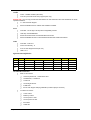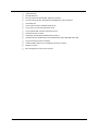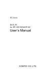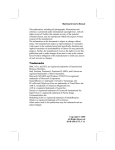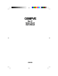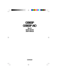
1
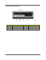
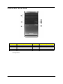
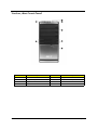
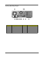
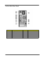
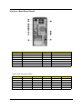
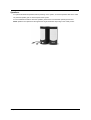
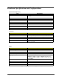
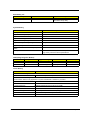
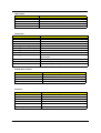
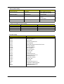
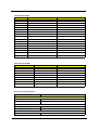
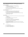
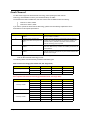
Chapter 1
System Specifications
Overview
VTX800 series are business-ready desktop PCs built with latest, high-performance technology for
managing demanding workloads. It is standalone or network-ready for SMB and includes video and audio
features for business multimedia.
In “stable technology”, we choose Intel Pentium4 processor, Intel 945G + ICH7 chipset architecture. The
combination can run at 1066/800 MHz front side bus, which gives more performance than other processors.
We also provide 1 PCI-Express x16 slot for add-on graphic solution, 1 PCI-Express x1 slot and 2 PCI slots, 4
Dual channel DDR2 memory slots, one parallel ATA port, four serial ATA2 prots, and onboard Gigabit LAN,
onboard Audio function.
There are three knids of chassis for Veriton series: Veriton 7800 for Mini-tower, Veriton 5800 for Desktop
and Veriton 6800 for Micro-tower which can fulfill all segment customers: expandability, middle-to-heavy
performance, and space saving.
Chapter 1
1
Features
CPU
T
Socket Type : Intel Socket T
T
Supports Intel Pentium 4 Prescott 775 / Smithfield FSB 800/1066MHz
T
Supports Intel Celeron Prescott 775 / FSB 533MHz
T
Pentium 4 2.66GHz ~3.8GHz speed
T
Celeron D2.53GHz ~ 3.2GHz
T
L2 Cache varies with CPU
Chipset
T
Northbridge: Intel Lakeport-G
T
Southbridge: Intel ICH7
Memory
T
Socket Type : DDR II,1.8 Voltage
T
Socket Quantity : 4, support Dual Channel
T
Capacity support : 256MB ~ 4GB
T
Support Memory Speed : 400/533/667 MHz
Graphic Solution
T
Intel Lakeport-G on-die graphic solution
T
PCI-E x16 VGA Add-On Card
Slots
T
1 PCI Express x16 slot
T
1 PCI Express x1 slot
T
2 PCI 2.2 5V slots
T
One 1.44MB 3.5” device
FDD
PATA IDE
T
Slot Type : 40pin PATA IDE slot
T
Slot Quantity : 2
T
Transfer rate support PIO mode 0 (3.33MB/s) /1 (5.22MB/s) /2 (8.33MB/s) /3 (11.1MB/s) /
4 (16.7MB/s)
T
ATA mode : 33/66/100/133
T
Device Type Support : HDD/CD-ROM/DVD-ROM/Combo/DVD burner
SATA IDE
2
T
Slot Type: SATA IDE slot
T
Slot Quantity : 4
T
Storage Type Support : HDD/CD-ROM/CD-RW/DVD-ROM/DVD-RW/DVD+RW/DVD Dual/DVD
Supermultiplus
Chapter 1
Audio
T
Codec : Realtek ALC880 (HD Codec)
T
One UAJ (Universal Audio Jack) support (rear only)
Remark UAJ : UAJ not only provides the ideal solution for multi-media and also user-friendliness for audio
speaker installation.
T
7.1 Channel Audio Support
T
Reserved disable function on BIOS side. Default is enabled.
T
Controller : PCI-E Giga LAN chip with manageability function
T
LAN Chip : Marvell 88E8052
T
Should be worked under 10/100/1000 Mbs environment
T
Reserved disabled function on both hardware & BIOS side. Default is enabled
T
Controller : Intel ICH7
T
Connectors Quantity : 8
T
Four for front daughter board (Pin:2*5 )
T
USB 2.0/1.1
LAN
USB
System LED Definition
Chasis
H701
Bezel
V751
H500
H401
Power LED
HDD LED
LAN LED
S0
S1,S3
S4,S5
Blue
Blue Blinking
OFF
Blue
Blue
ODD LED
Blue
H500
Green
Green Blinking
OFF
Green
Green
N/A
V451
Blue
Blue Blinking
OFF
Blue
Blue
Blue
A451
Blue
Blue Blinking
OFF
Blue
Blue
Blue
On-Board Connector
T
T
Chapter 1
Rear I/O Connectors
T
1 PS/2 Keyboard Port, 1 PS/2 Mouse Port
T
1 Parallel Port, 1 Serial Port
T
1 VGA Port
T
1 RJ45 GigaLAN Port
T
4 USB Ports
T
6 Ports Jack Support HD (High Definition) Audio Output(5.1 channel)
On-Board Connectos
T
1 CPU Socket
T
4 Memory Socket
T
1 PCI Express x1 Slot
T
1 PCI Express x16 Slot
T
2 PCI Slots
T
1 FDD Slot
3
4
T
1 PATA IDE Slots
T
4 SATA2 IDE Slots
T
2 2*5 pin Intel FPIO sepecification USB pin connectors
T
1 2*5 pin Intel FPIO spec. Microphone In/Headphone Out pin connectors
T
1 2nd serial port
T
1 CD-In 4pin connector (CD-ROM Audio Input)
T
1 4 pin CPU Fan connector with linear circuit
T
1 3 pin System FAN connectors with linear circuit
T
1 Intrusion ALarm connector
T
1 24pin/4pin ATX interface PS3/PS2 SPS connector
T
1 2*5pin Intel FPIO specification Power Switch/Power State LED/HDD active LED
T
1 2 pin LAN activity monitor connector
T
1 reserved GPIO connector for “One Button Recovery” function
T
1 Buzzer on board
T
Color management for on board connector
Chapter 1
Block Diagram
LGA775
Processor
PCI-ECLK
(100MHz)
Host
Interface
CPUCLK+/-(200/133MHz)
DDRII 667/533/400MHz DIMM
PCI Express x16
Intel
945G
MCH
Dual Channel Memory
MCHCLK (133/200MHz)
66MHz
33MHz
14.318MHz
48MHz
1 PCI Express x 1 Port
PCI-ECLK(100MHz)
BIOS
PCI Express x1 Bus
PCI Bsu
4 Serial ATA
ATA33/66/100
IDE Channels
Intel ICH7
Floppy
88E8052
LPT Port
SMC
LPC47M182
COM Ports
2 PCI
PCICLK
(33MHz)
Chapter 1
CODEC
Center/Subwoofer Speaker Out
Surround Speaker Out
Side Speaker Out
MIC
Line-Out
Line-In
SPDIF In
SPDIF Out
RJ45
24MHz
8 USB
Ports
33MHz
PS/2 KB/Mouse
5
MainBoard Placement
LPC47M182
KB_MS
ATX_12V
LAN
USB
USB
LGA775
ATX
8I945AE
VGA
IR
LPT
COMA
CPU_FAN
Intel 945G
AUDIO1
PCIE_12V
IDE
DDRII4
ICH7
-AE
BAT
CD_IN
RESV2
PCIE_1
RESV1
SPDIF COMB
CODEC
RECOVERY
CI
SYS_FAN
F_USB1
TPM
F_USB2
F_PANEL
S_ATA1 S_ATA3
BIOS
S_ATA0 S_ATA2
PCI2
DDRII3
PCI1
DDRII2
DDRII1
PCIE_16
88E8052
FDD
AUDIO2
CLR_CMOS
F-AUDIO
LOCKER
LOCK_RST
6
Chapter 1
Rear I/O Port
Item
Name
a
PS/2 Keyboard and PS/2 Mouse
Connector
To install a PS/2 port keyboard and mouse, plug the mouse to the
upper port (green) and the keyboard to the ower port (purple).
Description
b
LPT Port (Parallel Port)
The parallel port allows connection of a printer, scanner and other
peripheral devices.
c
COM (Serial Port)
Connects to serial-based mouse or data processing devices.
d
VGA Port
Monitor can be connected to VGA port.
f
USB Ports
Before you connect your device(s) into USB connector(s), please
make sure your device(s) such as USB keyboard, mouse, scanner,
zip, speaker...etc. have a standard USB interface. Also make sure
your OS supports USB controller. If your OS does not support USB
controller, please contact OS vendor for possible patch or driver
upgrade. For more information please contact your OS or device(s)
vendors.
g
LAN Port
The provided Internet connection is Gigabit Ethernet, providing data
transfer speeds of 10/100/1000Mbps.
h
Line In
Devices like CD-ROM, walkman etc. can be connected to Line In
jack.
i
Line Out
Connect the stereo speakers or earphone to this connector.
j
MIC In
Microphone can be connected to MIC In jack.
k
Rear Speaker Out
COnnect the rear surround speakers to this connector
l
Center/Subwoofer Speaker Out
Connect the Center/Subwoofer speakers to this connector
m
Side Speaker Out
Connect the side surround speakers to this connector
Chapter 1
7
Veriton 5800 Front Panel
No.
8
Description
No.
2
Description
1
Optical Device
Floppy drive
3
Microphone-in jack
4
Speaker-out/line-out port
5
USB ports
6
One Button Recovery hole
7
Indicators
8
Power button
Chapter 1
Veriton 6800 Front Panel
No.
1
Description
Optical Device
No.
2
Description
Floppy drive
3
Microphone-in jack
4
Speaker-out/line-out port
5
USB ports
6
Indicators
7
Power button
NOTE: The specifications above are for reference only. The exact configuration of your PC depends on the
model purchased.
Chapter 1
9
Veriton 7800 Front Panel
No.
10
Description
No.
Description
1
Optical Device
2
Floppy drive
3
Microphone-in jack
4
Speaker-out/line-out port
5
USB ports
6
Indicators
7
Power button
Chapter 1
Veriton 5800 Rear Panel
No.
Chapter 1
Description
No.
2
Description
1
Power supply
Power cord socket
3
Voltage selector switch
4
PS/2 mouse port
5
PS/2 Keyboard port
6
Serial port
7
Printer connector
8
Monitor connector
9
USB 2.0 ports
10
RJ-45 Ethernet connector
11
Audio jack
12
Expansion slots
13
Chassis lock pad
11
Veriton 6800 Rear Panel
No.
12
Description
No.
Description
1
Power supply
2
Power cord socket
3
Voltage selector switch
4
PS/2 mouse port
5
PS/2 Keyboard port
6
Serial port
7
Printer connector
8
Monitor connector
9
USB 2.0 ports
10
RJ-45 Ethernet connector
11
Audio jack
12
Expansion slots
13
Chassis lock pad
Chapter 1
Veriton 7800 Rear Panel
No.
Description
No.
2
Description
1
Power supply
Power cord socket
3
Voltage selector switch
4
PS/2 mouse port
5
PS/2 Keyboard port
6
Serial port
7
Printer connector
8
Monitor connector
9
USB 2.0 ports
10
RJ-45 Ethernet connector
11
Audio jack
12
Expansion slots
13
Chassis lock pad
Audio Jack Function Table
Color/Use
Headphone
1.1 CH
3.1 CH
5.1 CH
7.1 CH
Blue
Line-in
Line-in
Line-in
Line-in
Line-in
Green
Headphone
Line-out
Front
Front
Front
Pink
Mic-in
Mic-in
Mic-in
Mic-in
Mic-in
Orange
Center&woofer
Center&woofer
Center&woofer
Center&woofer
Center&woofer
Black
Rear
Rear
Rear
Rear
Rear
Gray
Side
Side
Side
Side
Side
Chapter 1
13
System Peripherals
The Aspire T630 and AcerPower F3 computer consist of the system itself, and system peripherals, like a
mouse, keyboard and a set of speakers (optional). This section provides a brief description of the basic
system peripherals.
Mouse (PS/2 or USB, manufacturing option)
The included mouse is a standard two-button wheel mouse. Connect the mouse to the PS/2 mouse port or
USB port on the back panel of the system.
Keyboard (PS/2 or USB, manufacturing option)
Connect the keyboard to the PS/2 keyboard port or USB port on the back panel of the system.
14
Chapter 1
Speakers
Note:
For systems bundled with speakers, before powering on the system, connect the speaker cable to the audio
out (external speaker) port on the back panel of the system.
For more detailed information about the speakers, please refer to the included operating instructions.
NOTE: speakers are optional and the appearance might be different depending on the actual product.
Chapter 1
15
Acer eRecovery
Acer eRecovery is a tool to quickly backup and restore the system. Users can create and save a
backup of the current system configuration to hard drive, CD, or DVD.
Acer eRecovery consists of the following functions:
1.
Create backup
2.
Restore from backup
3.
Create factory default image CD
4.
Re-install bundled software without CD
5.
Change Acer eRecovery password
Create backup
Users can create and save backup images to hard drive, CD, or DVD.
1.
Boot to Windows XP
2.
Press <Alt>+<F10> to open the Acer eRecovery utility.
3.
Enter the password to proceed. The default password is six zeros.
4.
In the Acer eRecovery window, select Recovery settings and click Next
5.
In the Recovery settings window, select Backup snapshot image and click Next.
6.
Select the backup method.
T
Use Backup to HDD to store the backup disc image on drive D:.
T
Backup to optical device to store the backup disc image on CD or DVD (only available on
systems that include an optical disc burner).
7.
After choosing the backup method, click Next.
Follow the instruction on screen to complete the process.
Restore from backup
Users can restore backup previously created (as stated in the Create backup section) from hard drive,
CD, or DVD.
1.
Boot to Windows XP.
2.
Press <Alt>+<F10> to open the Acer eRecovery utility.
3.
Enter the password to proceed. The default password is six zeros.
4.
In the Acer eRecovery window, select Recovery actions and click Next.
5.
Select the desired restore action and follow the onscreen instructions to complete the restore process.
Create factory default image CD
When the System CD and Recovery CD are not available, you can create them by using this feature.
16
1.
Boot to Windows XP.
2.
Press <Alt>+<F10> to open the Acer eRecovery utility.
3.
Enter the password to proceed. The default password is six zeros.
4.
In the Acer eRecovery window, select Recovery settings and click Next.
5.
In the Recovery settings window, select Burn image to disc and click Next.
6.
In the Burn image to disc window, select 01. Factory default image and click Next.
Chapter 1
7.
Follow the instructions on screen to complete the process.
Re-install bundled software without CD
Acer eRecovery stores pre-loaded software internally for easy driver and application re-installation.
1.
Boot to Windows XP.
2.
Press <Alt>+<F10> to open the Acer eRecovery utility.
3.
Enter the password to proceed. The default password is six zeros.
4.
In the Acer eRecovery window, select Recovery actions and click Next.
5.
In the Recovery settings window, select Reinstall applications/drivers and click Next.
6.
Select the desired driver/application and follow the instructions on screen to re-install.
At first launch, Acer eRecovery prepares all the needed software and may take few seconds to bring up the
software content window.
Change Password
Acer eRecovery and Acer disc-to-disc recovery are protected by a password that can be changed by
the user. Follow the steps below to change the password in Acer eRecovery.
1.
Boot to Windows XP.
2.
Press <Alt>+<F10> to open the Acer eRecovery utility.
3.
Enter the password to proceed. The default password is six zeros.
4.
In the Acer eRecovery window, select Recovery settings and click Next.
5.
In the Recovery settings window, select Password: Change Acer eRecovery password and click Next.
6.
Follow the instructions on screen to complete the process.
Chapter 1
17
Acer disc-to-disc recovery
Restore without a Recovery CD
This recovery process helps you restore the C: drive with the original software content that is installed when
you purchase your notebook. Follow the steps below to rebuild your C: drive. (Your C: drive will be
reformatted and all data will be erased.) It is important to back up all data files before you use this option.
1.
Restart the system.
2.
While the Acer logo is showing, press <Alt>+<F10> at the same time to enter the recovery process.
3.
The message "The system has password protection. Please enter 000000:" is displayed.
4.
Enter six zeros and continue.
5.
The Acer Recovery main page appears.
6.
Use the arrow keys to scroll through the items (operating system versions) and press <Enter> to select.
Multilingual operating system installation
Follow the instructions to choose the operating system and language you prefer when you first power-on the
system.
18
1.
Turn on the system.
2.
Acer's multilingual operating system selection menu will pop-up automatically.
3.
Use the arrow keys to scroll to the language version you want. Press <Enter> to confirm your selection.
4.
The operating system and language you choose now will be the only option for future recovery
operations.
5.
The system will install the operating system and language you choose.
Chapter 1
Hardware Specifications and Configurations
System Board Major Chip
Item
Specification
System Core Logic
Intel 945G Express chipset
Intel ICH7
Super I/O Controller
LPC47M182
LAN Controller
Intel ICH7
Memory Controller
Build in Intel 945G
E-IDE Controller
Build in Intel ICH7
RJ45 Controller
88E8052
Audio Controller
Intel ICH7
VGA Controller
Intel 945G
Keyboard Controller
LPC47M182
Processor
Item
Specification
Type
Intel Pentium 4 processor 775 Land Grid Array(LGA)
Slot
Socket-T (LGA 775)
Speed
Depends on CPU, which is local configured
Bus Frequency
533/800/1066 MHz
Voltage
Processor voltage can be detected by any system without
setting any jumper
BIOS
Item
Specification
BIOS code programmer
Award
BIOS version
R01-A1
BIOS ROM size
4MB
BIOS ROM package
32-pin PLCC package
Support protocol
PCIX 1.0,PCI 2.2,APM 1.2,VESA/DPMS (VBE/PM V1.1),
SMBIOS 2.3, E-IDE 1.1, ACPI 1.0b,ESCD1.03, PnP 1.0a,
Bootable CD-ROM 1.0, USB 1.1~ USB 2.0, UHCI 1.0, ANSI
ATA 3.0 ATAPI
Boot from CD-ROM feature
Yes
Support to LS-120 drive
Yes
Support to BIOS boot block feature
Yes
BIOS Password Control
Yes
The BIOS can be overwritten/upgraded by using “AFLASH” utility (AFLASH.EXE).
Chapter 1
19
BIOS Hotkey List
Hotkey
Function
Description
Enter BIOS Setup Utility
c
Press while the system is booting to
enter BIOS Setup Utility.
System Memory
Item
Specification
Memory Slot Number
4 Slots
Supported Memory Size per Slot
256 MB ~ 1GB
Supported Maximum Memory Size
4GB
Supported Memory Speed
533/667 MHz
Supported memory voltage
1.8 V
Support memory module package
240-pin DIMM
Support to parity check feature
Yes
Support to Error Correction Code (ECC)
feature
Yes
Memory module combinations
You can install memory modules in any combination as
long as they match the above specifications.
VRM (Voltage Regulator Module)
Function
VRM Specification
Typical Voltage
Power Source
Maximum Output
CPU VRM
VRM10.1
0.8375~1.6v
12 Voltage
101A
CPU VRM
VRM 9.0
1.1-1.85 Voltage
12 Voltage
70A
Cache Memory
Item
Specification
First-Level Cache Configurations
Cache function control
Enable/Disable by BIOS Setup
Second-Level Cache Configurations
The information below is only applicable to system installed with a Pentium 4 processor
20
Tag RAM Location
On Processor
L2 Cache RAM Location
On Processor
L2 Cache RAM type
PBSRAM (Pipelined-burst Synchronous RAM)
L2 Cache RAM size
Depends on CPU, which is local configured
L2 Cache RAM speed
Full of the processor core clock frequency (Advanced Transfer Cache)
L2 Cache function control
Enable/Disable by BIOS Setup
L2 Cache scheme
Fixed in write-back
Chapter 1
LAN Interface
Item
Specification
LAN Controller
88E8052 LAN Controllers
LAN Controller Resident Bus
PCI Bus
LAN Port
ONE RJ-45 on board
Function Control
Enable/Disable by BIOS Setup
IDE Interface
Item
Specification
IDE Controller
Built-in Intel ICH7
IDE Controller Resident Bus
PCI bus
Number 40 pin PATA slot
1
T
Device Type Support
HDD, CD-ROM, CD-RW, DVD-ROM,Combo,DVD burner
T
Transfer Rate Support
PIO 0/1/2/3/4
T
ATA Mode
33/66/100
Number STAT IDE slot
T
Device Type Support
4
HDD,CD-ROM,CD-RW,DVD-ROM,DVD-RW,DVD+RW,DVD Dual,DVD
Supermultiplus
Supports LS-120
Yes
Supports bootable CD-ROM
Yes
Function Control
Enable/Disable by BIOS setup
Diskette Drive Interface
Item
Specification
Diskette Drive Controller
LPC47M182
Diskette Drive Controller Resident Bus
LPC Bus
Supported Diskette Drive Formats
1.44MB, 2.88MB format and slim type diskette drive
Function Control
Enable/Disable by BIOS Setup
Serial Port
Item
Specification
Serial port controller
LPC47M182
Serial port controller resident bus
LPC Bus
Number of serial port
1
Serial port location
Rear panel
16550 UART support
Yes
Connector type
9-pin D-type female connector
Chapter 1
21
USB Port
Item
Specification
Universal HCI
USB 2.0/1.1
Controller
Intel ICH7
Number of the connectors
8
Location
Rear : 4
On-board header : 4
USB Class
Support legacy keyboard for legacy mode
Wake-up Event Specifications
Device
S1
S3
S4
S5
Power Button
Enabled
Enabled
Enabled
Enabled
PS2 Keyboard
Disabled
Disabled
Disabled
Disabled
USB Keyboard
Disabled
Disabled
N/A
N/A
PME
Disabled
Disabled
Disabled
Disabled
WOR (wake on Ring)
Disabled
Disabled
Disabled
Disabled
RTC (real time clock)
Disabled
Disabled
Disabled
Disabled
Thermal Design
Item
Description
Thermal Design
T
Provision for optional secondary fan
T
Adequate venting in the front of chassis
T
Adequate venting in the rear of chassis
Memory Address Map
Address
22
Size
Function
0000000 - 009FFFF
640 KB System Memory
Onboard DRAM
00A0000-00BFFFF
128 KB Video RAM
Reserved for Graphics Display
Buffer
Non-Cacheable
00C0000-00CFFFF
32 KB I/O Expansion ROM
Reserved for ROM on I/O
Adapters
00D0000-00D3FFF
16 KB I/O Expansion ROM
Reserved for ROM on I/O
Adapters
00D4000-00D7FFF
16 KB I/O Expansion ROM
Reserved for ROM on I/O
Adapters
00D8000-00DBFFF
16 KB I/O Expansion ROM
Reserved for ROM on I/O
Adapters
00DC000-00DFFFF
16 KB I/O Expansion ROM
Reserved for ROM on I/O
Adapters
00E0000-00E7FFF
32 KB for SCSI BIOS
Reserved for SCSI BIOS
00E8000-00EFFFF
32 KB
Reserved Onboard
Chapter 1
Memory Address Map
Address
Size
Function
00F0000-00FFFFF
64 KB BIOS
System ROM BIOS (ROM)
System RAM BIOS (DRAM)
0100000-0F9FFFF
System Memory
Onboard DRAM
0FA0000-0FFFFFF
384 KB I/O Card Memory
Reserved for Memory Map
I/O Card
Non-Cacheable
1000000-FFFFFFF
System Memory
Onboard DRAM
PCI INTx# and IDSEL Assignment Map
PCI INTx #
PCI Devices
Device IDSEL: ADxx
INTA#
ADIMM-slot
N
INTB#
PCI-Slot1
AD16
INTC#
PCI-Slot2
AD17
I/O Address Map
Hex Range
000-01F
020-021
040-043
060-060
061-061
070-071
080-08F
0A0-0A1
0C0-0DF
0F0-0FF
170-177
1F0-1F7
278-27F
2F8-2FF
378-37F
3F0-3F5
3F6-3F6
3F7-3F7
3F8-3FF
0CF8
0CFC
778-77A
Chapter 1
Devices
DMA Controller-1
Interrupt Controller-1
System Timer
Keyboard Controller 8742
System Speaker
CMOS RAM Address and Real Time Clock
DMA Page Register
Interrupt Controller-2
DMA Controller-2
Math Co-Processor
Secondary IDE
Primary IDE
Parallel Printer Port 2
Serial Asynchronous Port 2
Parallel Printer Port 1
Floppy Disk Controller
Secondary IDE
Primary IDE
Serial Asynchronous Port 1
Configuration Address Register
Configuration Data Register
Parallel Printer Port 1
23
IRQ Assignment Map
IRQx
System Devices
Add-On-Card Devices
IRQ0
Timer
N
IRQ1
Keyboard
N
IRQ2
Reserved
N
IRQ3
Serial Port 2
Reserved
IRQ4
Serial Port 1
Reserved
IRQ5
Reserved
Reserved
IRQ6
Floppy Disk
Reserved
IRQ7
Parallel Port
Reserved
IRQ8
Real Time Clock
N
IRQ9
N
Reserved
IRQ10
N
Reserved
IRQ11
N
Reserved
IRQ12
PS/2 Mouse
Reserved
IRQ13
Numeric Processor
N
IRQ14
Embedded Hard Disk
Reserved
IRQ15
Reserved
Reserved
NOTE: N - Not be used
DRQ Assignment Map
DRQx
System Devices
Add-On-Card Devices
DRQ0
N
Reserved
DRQ1
N
Reserved
DRQ2
FDD
N
DRQ3
N
Reserved
DRQ4
Cascade
N
DRQ5
N
Reserved
DRQ6
N
Reserved
DRQ7
N
Reserved
NOTE: N - Not be used
Environmental Requirements
Item
Specifications
Temperature
Operating
+5°C ~ +35°C
Non-operating
-20 ~ +60°C (Storage package), -10°C~+60°C (un-package)
Humidity
Operating
15% to 80% RH, non-condensing
Non-operating
10% to 90% RH, non-condensing at 40°C
Vibration
Operating (unpacked)
24
5 ~ 500Hz, 2.20g RMS random,10 minutes per axis in all 3 axes
Chapter 1
Environmental Requirements
Item
Specifications
Non-operating (packed)
5 ~ 500Hz, 1.09g RMS random,1 hour per axis in all 3 axes
Shock Operating
Half sine, 2g 11m seconds
Drop Test
Drop Test
Definition
The protection ability of packing & cushion must be capable of withstanding, with no physical or
functional demage, mechanical impact from height-specific drops.
Test Standard
Package Cross Weight
KGs
Drop Height
lbs
CM
Not of Drop
Inch
0~9.1
0~20
76
30
10
9.1~18.2
20~40
61
24
10
18.2~27.3
40~60
46
18
10
27.3~45.4
60~100
31
12
10
10 drops : one corner, three edges, six surfaces
Chapter 1
25
Power Management Function ( ACPI support function)
Device Standby Mode
T
Independent power management timer for hard disk drive devices
(0-15 minutes, time step=1 minute).
T
Hard disk drive goes into Standby mode (for ATA standard interface).
T
Disable V-sync to control the VESA DPMS monitor.
T
Resume method: device activated (Keyboard for DOS, keyboard & mouse for Windows).
T
Resume recovery time: 3-5 sec.
Global Standby Mode
T
Global power management timer (2-120 minutes, time step=10 minute).
T
Hard disk drive goes into Standby mode (for ATA standard interface).
T
Disable H-sync and V-sync signals to control the VESA DPMS monitor.
T
Resume method: Return to original state by pushing external switch button, modem ring in,
keyboard and mouse for APM mode.
T
Resume recovery time: 7-10 sec.
Suspend Mode
T
Independent power management timer (2-120 minutes, time step=10 minutes) or pushing external
switch button.
T
CPU goes into SMM.
T
CPU asserts STPCLK# and goes into the Stop Grant State.
T
LED on the panel turns amber colour.
T
Hard disk drive goes into SLEEP mode (for ATA standard interface).
T
Disable H-sync and V-sync signals to control the VESA DPMS monitor.
T
Ultra I/O and VGA chip go into power saving mode.
T
Resume method: Return to original state by pushing external switch button, modem ring in,
keyboard and mouse for APM mode.
T
Return to original state by pushing external switch button, modem ring in and USB keyboard for
ACPI mode.
T
ACPI specification 1.0b.
T
S0, S1, S3 and S5 sleep state support.
T
On board device power management support.
T
On board device configuration support.
ACPI
26
Chapter 1
Dual Channel
VT x800 series support the Dual Channel Technology. After operating the dual channel
technology, the bandwidth of memory bus will add double up to 4GB/s.
The mainboard inculdes 4 DIMM slots, and each channel has two DIMM sockets as following:
T
Channel A : DDR1, DDR3
T
Channel B : DDR2 , DDR4
If you want to operate the Dual Channel Technology, please note the following explanations due to
the limitation of Intel chipset specifications.
Memory Number
Description
1
Only one DDR memory module is
installed ?
The Dual Channel Technology can’t operate when only one DDR
memory module is installed.
2
Two DDR memory modules are
installed ( the same memory size and
type) ?
The Dual Channel Technology will operate when two memory
modules are inserted individually into Channel A and B. If you
install two memory modules in the same channel, the Dual
Channel Technology will not operate.
3
Three DDR memory modules are
installed ?
Pleae note that the Dual Channel Technology will not operate
when three DDR memory modules are installed; part of them will
not be detected.
4
Four DDR memory modules are
installed ?
If you install four memory modules at the same time, the Dual
Channel Technology will operate only when those modules have
the same size and type.
NOTE: We strongly recommend user to slot two DDR memory modules into the DIMMs with the same color in
order for Dual Channel Technology to work.
The following tables include all memory-installed combination types:
Dual Channel Technology (DS: Double Side, SS: Single Side)
DDR1
DDR2
DDR3
DDR4
2 memory modules
DS/SS
X
DS/SS
X
X
DS/SS
X
DS/SS
4 memory modules
DS/SS
DS/SS
DS/SS
DS/SS
Don’t operate Dual Channel Technology (DS:Double Side, SS: Single Side)
DDR1
1 memory module
2 memory module
3 memory module
Chapter 1
DDR2
DDR3
X
DDR4
DS/SS
X
X
X
DS/SS
X
X
X
X
DS/SS
X
X
X
X
DS/SS
DS/SS
DS/SS
X
X
X
X
DS/SS
DS/SS
DS/SS
DS/SS
DS/SS
X
DS/SS
DS/SS
X
DS/SS
DS/SS
X
DS/SS
DS/SS
X
DS/SS
DS/SS
DS/SS
27