1
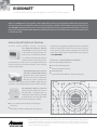
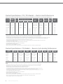
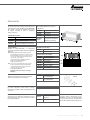
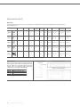
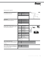
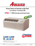
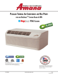
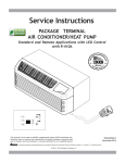
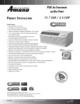
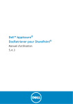
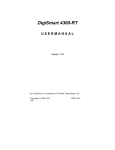
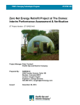
PACKAGE TERMINAL AIR CONDITIONER (PTAC) AND HEAT PUMP Specifications and Accessories Catalog Wise Decision. It’s an Amana® brand. Amana is a registered trademark of Maytag Corporation or its related companies and is used under license to Goodman Company, L.P., Houston, TX, USA. All rights reserved. Premium Amana® Brand Quality Featuring DigiSmart ® Web-Based Monitoring DIGISMART® A Combination of Energy Management and PTAC Performance Amana® brand DigiSmart® brings together our best PTAC with our best energy management software that now integrates with optional property management and front desk management software. Reduce PTAC energy consumption up to 35% OR MORE* through the power of the in-unit energy management system, programmable temperature set-back, and temperature limiting combined. Our Maintenance Notification System can alert when there is a potential maintenance issue with the PTAC. Amana brand DigiSmart Solution In - Ro om "Self- Installable" Wireles s Peripherals The DigiSmart Wireless Remote Thermostat can be mounted on the wall anywhere in the guest room. It is Battery powered and with its own wireless ability to communicate with the PTAC to maintain room temperature. Best of all, there are no wires to run. The PTAC and thermostat connect at the press of a button and work in-sync to display accurate temperature. The DigiSmart Occupancy Sensor and Door Switch Combo Device completes the in-room equipment. This infrared sensor can determine whether the room is occupied or empty and when empty, signal the PTAC to adjust the temperature to save energy based on programmable set-backs. The DigiSmart Wireless Antenna installs inside the PTAC with a snap-in connector like a telephone jack. Installing the antenna allows the PTAC to communicate wirelessly with other devices in the room and to the DigiSmart network. ■■ 60,000+ rooms have had wireless installations since 2005 ■■ Total wireless devices deployed to date: 425,000+ The Amana brand DigiSmart PTAC with antenna, combined with the self-installable, wireless thermostat and occupancy sensor give the property owner complete control over the equipment settings and can reduce PTAC energy usage up to 35% OR MORE.* Site-Level — Central Wireless Controller ■■ Site-wide PTAC Configuration ■■ Site-wide PTAC Diagnostics ■■ Front-Desk System Interface ■■ Email Reporting ■■ Internet Accessible Web User Interface Enterprise DigiSmart Controller * These savings represent estimated savings over time and were generated using general assumptions including energy loads, local weather averages and use of occupancy controls. Actual savings will vary according to actual use habits, room square footage, and how the unit is installed and maintained. www.amana-ptac.com Data Warehouse Site Managment Ent Maintenance Staff Internet DigiSmart Controller Site #1 r se o ess Acc Enterprise DigiSmart Controller Enterprise – Multiple Wireless Controllers Owner orm Central Monitoring and Control of Multiple Properties or Platform Access Sig na l l na Sig Front Desk Staff ri erp Platf General Managers DigiSmart Controller Site #2 ■■ Data Warehousing ■■ Load Shedding ■■ Virtual Metering ■■ Email Reporting ■■ Savings Analysis Site #3 Web-Based Monitoring – Amana® brand DigiSmart® Controller All PTACs in a building can be managed through a single interface on a PC. Features Include: ■■ Full unit details for every PTAC, visible from the front desk or home office ■■ Automatic emails for PTAC maintenance ■■ Ability to change all settings on the unit ■■ Enhanced diagnostics ■■ Monitors up to 170 PTACs WIRELESSLY with one controller ■■ Expand the network with additional controllers –– System Verification – Site Statistics –– Global Setbacks – Email Reporting –– EMS Configuration – Unit Health –– Site Statistics – Unit Code Alerts Unrented Set-Points By integrating with your property’s Front Desk System, the PTACs will adjust to specific set-points when no longer identified as rented in the system. Temp Limiting Each PTAC can be configured with a heating and cooling temperature set-point limit. Set-backs Once a room is declared unoccupied by the occupancy sensor, the PTAC progresses through three different temperature set-backs, configured as three degree and time pairs (An example configuration is listed below). 1. 2°, 30 mins – Setback the temp 2 degrees after 30 minutes 2. 4°, 1 hr – Setback the temp 2 more degrees after 30 more minutes 3. 8°, 3 hrs – Setback the temp 4 more degrees after 2 more hours Talk to your Amana brand dealer about opportunities to optimize the efficiency of your new unit. Before purchasing this appliance, read important information about its estimated annual energy consumption, yearly operating cost or energy efficiency rating that is available from your dealer. www.amana-ptac.com 3 Standard Features ■■ ■■ Energy Efficiencies: With EERs up to 11.7 and COPs up to 3.5, our unit’s high efficiencies may qualify you for many of the rebates offered by electrical power companies. Quiet Operation: Our PTAC has been redesigned to be the quietest PTAC we’ve ever built. The unit’s stateof-the-art design and construction provide a quiet environment, allowing guests to enjoy peaceful, sleep-filled nights. ■■ ■■ ■■ –– Two fan motors (indoor/outdoor) –– Indoor tangential fan for quiet operation –– STC of 28 ■■ ■■ ■■ ■■ ■■ 4 Assembled in the USA for 35 years: assembled at our plant in Fayetteville, TN, using Goodman resources including engineering, production, and testing. ■■ Increased Dehumidification Capacity: Maintain lower humidity levels in rooms while cooling them without the need for expensive add-ons. As a result, guests feel more comfortable at higher temperatures, thus reducing cooling costs. Seven-Button Touch Pad: Provides complete control to guests for in-room comfort while maintaining energy efficiency. Five-Year Limited Warranty: Enjoy one of the most comprehensive warranties in the industry: First Year: parts & labor; Second through fifth years: parts & labor on certain sealed system components; second through fifth years: on certain functional parts only. For complete warranty details, visit www.amana-ptac.com. 100% Run Tested: All units are 100% run tested at our plant in Fayetteville, TN, including leak checks during manufacturing and again prior to shipment at the warehouse. www.amana-ptac.com ■■ 7⅝" Unit Front Depth: Enhance valuable room space with our slim unit front, which has a sleek 7⅝" depth, one of the shallowest silhouettes in the industry today. In addition, to inhibit guesttampering, the front can be secured to the chassis with a hidden screw. Easy Pull-Out Filters: Our filters are washable and easy to maintain. Filter Dryer for Sealed System Refrigerant: Standard in all units to protect the compressor and lengthen the life of the unit by removing moisture and preventing acid formation. Condensate Dispersion System: Our condensate dispersion system removes condensate from indoor cooling operation by throwing water directly on to the outdoor coil for rapid evaporation and increased cooling efficiencies. The slinger ring on the new, enhanced fan draws water up and into the fan blades. This water is then atomized and evaporated into the atmosphere through the condenser. Increased surface area from the coil allows more water to be evaporated on the sides of the coils and helps to minimize condensate run-off. Front Desk Control: Each unit comes equipped with the DigiSmart™ control and energy management software. Using the DigiSmart™ software and optional RF Antenna, all units can be wirelessly connected to a central hub for enhanced energy savings and diagnostics. Amana brand PTACs also have a lowvoltage interface capability with a field-supplied front-desk ON/OFF switch. (See inside front cover.) ■■ ■■ ■■ ■■ ■■ ■■ ■■ Room Freeze Protection: When the unit senses temperatures of 40°F or below, the unit activates the fan motor and either the electric resistance heater or the hydronic heater. Easy-to-use Controls: No complex controls to confuse your guests and create phone calls for your manager. Controls are easy to read, understand, and activate. Our new 7-button control panel provides guests with complete control of the unit for their in-room comfort while maintaining overall energy efficiency. Easy to Service with On-Board LED Diagnostics: The main components are easily serviced and there is no guessing to determine the problem with our easy-to-read diagnostics. Stonewood Room Front: Our Stonewood room front strikes the balance between attractive styling and practical design. Distinctive contours and a modern appearance enhance the character of even the most luxurious room, while the sleek 7⅝" depth maximizes usable space for your guests. Remote Thermostat Control: When the DigiSmart™ wireless remote thermostat (DS01E, sold separately) is set up, both the remote thermostat and unit control panel continue to control the unit, providing flexibility and home-like system control. Installation requires no more than pressing two buttons. No need to run wires or make electrical connections. Extended Heat Pump Heating: Heat pump models will operate in the heating mode down to as low as 24°F outdoor ambient temperature. Zero Floor Clearance: The unit can be installed flush to a finished floor, if desired. (Some accessories do not have zero clearance). ■■ ■■ ■■ ■■ ■■ ■■ 30-Second Fan-Off Delay: The fan continues to run 30 seconds after the compressor has stopped in either cooling or heat pump mode and after electric heat has been turned off. This improves efficiency by dispersing the conditioned air on the coils into the room. Compressor Lock-In: This feature helps prolong the life of the compressor by preventing short-cycling. When the compressor is switched from Off to On because room temperature has risen or fallen below the specified limit, it will remain on for at least 4 minutes. If the temperature set-point is changed during this 4 minutes, the lock-in feature is overridden. Automatic Emergency Heat: No more “my unit is not heating” complaints during the middle of the night. Heat pump units will automatically switch over to electric resistance heat if the heat pump compressor system fails or if the heating load is greater than the unit capacity. Constant Fan Mode: Take advantage of each unit’s dual options — select continuous fan operation or cycle the fan ON and OFF with the thermostat. Our 7-button design allows guests to select fan performance while allowing the owner to have the unit revert to the desired program of continuous fan or cycle with conditioning. Hidden Ventilation Control: The ventilation control lever is hidden from the occupant's view to allow you to manage ventilation requirements. High-Pressure Switch: Protects the unit from high pressure and damage to the unit, helping to ensure long unit life. Specifications and Accessories Catalog 5 Nomenclature PTC 07 3 G 35 AXXX AA 1,2,3 4,5 6 7 8,9 10,11,12,13 14,15 Basic Model Type Engineering PTC Standard Cooler PTAC PTH Standard Heat Pump PTAC DRY Dehumid Cooler PTAC Major & Minor Revisions Features Code A Standard Model Nominal Cooling Capacity C Corrision Protection (Seacoast) 07 09 10 12 15 17 D Power Door F Fuse Holder (230/208 Only) 7,000 BTU/h 9,000 BTU/h 10,000 BTU/h 12,000 BTU/h 15,000 BTU/h 17,000 BTU/h 60 Hz 60 Hz 50 Hz 50 Hz or 60 Hz 60 Hz 60 Hz H Hydronic Heat-Capable M Make-up Air (DigiAIR) P Condensate Pump (PTH Only) Q Quiet STC 31 Chassis RF Antenna Rated Voltage R 2 115V, 60 Hz, 1 Ph V Power Vent 3 230/208V, 60Hz, 1 Ph X placeholder 4 265V, 60Hz, 1 Ph W Hard-Wired (PTQC) 5 240/220V, 50Hz. 1 Ph Use up to 4 as needed in alphabetical order Design Series Examples G PTC123*50AXX PTC073*35RXX PTC123*50CXXX PTC073*25CQRW R-410A Heater Size 00 No Electric Heat 15 1.5 kW 25 2.5 kW 35 3.5 kW (230/208V) 3.7 kW (265V) 50 5.0kW Power Cord Configuration Power Receptacle Configuration Power Cord Plugs 250V Rating Power Cord Plugs with LCDI Device NEMA 6 Configuration 30 amp 20 amp 15 amp NEMA6-15R; 250V receptacle used on 230/208V units NEMA6-20R; 250V receptacle used on 230/208V units NEMA6-30R; 250V receptacle used on 230/208V units 20 amp 6 www.amana-ptac.com NEMA7-20R; 277V receptacle used on 265V units W W G G 277V Rating Power Cord Plugs NEMA 7 Configuration 30 amp NEMA7-30R; 277V receptacle used on 265V units All units come with factor-installed power cords. All units less than 250 volts come with LCDI device. Product Specifications: PTC Models — Cooling/Electric Heat 230/208 Volts Model 6, 8, 9 Voltage ³ Capacity (BTU/h) Amps ¹⁰ Watts ¹⁰ EER PTC 073G***XXX 230 / 208 7,700 / 7,700 3.5 / 3.5 670 / 658 11.5 / 11.7 PTC 093G***XXX 230 / 208 9,000 / 9,000 4.1 / 4.1 804 / 783 11.2 / 11.5 PTC 123G***XXX 230 / 208 12,000 / 11,700 5.6 / 5.6 1,114 / 1,085 10.4 / 10.5 PTC 153G***XXX 230 / 208 15,000 / 14,700 7.0 / 7.0 1,500 / 1,470 10.0 / 10.0 PTC 173G***XXX 230 / 208 16,400 / 16,200 8.4 1,740 / 1,720 9.4 4.2 290 264 310 282 65* 1.7 98 113 4.9 290 264 310 282 65* 2.2 102 117 6.8 290 264 310 282 65* 3.6 102 119 8.5 340 314 360 332 65* 4.4 113 130 10.2 340 314 360 332 65* 4.8 113 130 PTC 074G***XXX 265 7,700 3.0 670 11.5 PTC 094G***XXX 265 9,000 3.6 796 11.3 PTC 124G***XXX 265 12,000 4.8 1,165 10.3 PTC 154G***XXX 265 14,800 6.0 1,480 10.0 Unit without Electric Heater Min. Circuit Amps 2, 4, 10 CFM (Cool/Wet Coil) CFM (Dry Coil) Ventilated Air, CFM (Fan Only)* Dehumidification (Pints/Hr.) Net Weight (lbs.) Ship Weight (lbs.) High Low High Low 265/277 Volts Model 1, 6, 8 Voltage ¹, ³ Capacity (BTU/h) Amps ¹⁰ Watts ¹⁰ EER Unit without Electric Heater Min. Circuit Amps 2, 4,10 CFM (Cool/Wet Coil) CFM (Dry Coil) Ventilated Air, CFM (Fan Only)* Dehumidification (Pints/Hr.) Net Weight (lbs.) Ship Weight (lbs.) High Low High Low 3.6 4.4 5.9 7.4 290 264 310 282 65* 1.7 98 113 290 264 310 282 65* 2.2 102 117 290 264 310 282 65* 3.6 102 119 340 314 360 332 65* 4.4 113 130 * Actual vent CFM performance will vary due to application and installation conditions. Notes ¹ All 265-volt models must use an Amana® brand sub-base (PTSB4**E) or an Amana® brand hard-wire kit PTPWHWK4 and disconnect switch PSHW04A. ² Minimum Circuit Ampacity (MCA) ratings conform to the National Electric Code; however, local codes should apply. ³ Minimum voltage on 230/208-volt models is 197 volts; maximum is 253 volts. Minimum voltage on 265-volt models is 239 volts; maximum is 292 volts. ⁴ Overcurrent protection for all units without electric heaters is 15 amps. Overcurrent protection on 265-volt models must be cartridge-style time-delay fuses (included and factory-installed on all Amana® brand 265-volt chassis). See heater performance ⁵ Heating capacity and efficiency based on unit operation without condensate pump; unit automatically switches to electric heat at approximately 24°F outdoor ambient. ⁶ Specify two-digit heater kW size to complete model number. ⁷ R-410A refrigerant used in all systems. ⁸ All units meet or exceed ASHRAE 90.1 standards. ⁹ All units less than 250 volts have a Leak Current Detector Interrupter (LCDI) power cord and meet UL 484 standards. ¹⁰ Refer to electric heat performance data for total MCA and recommended overcurrent protection. Amps and Watts notation refers to compressor only. Specifications and Accessories Catalog 7 Product Specifications: PTH Models — Cooling/Heat Pump/Electric Heat Model 1, 6, 8, 9 PTH073G **AXXX PTH093G **AXXX PTH123G **AXXX PTH153G **AXXX PTH074G **AXXX PTH094G **AXXX PTH124G **AXXX PTH154G **AXXX Voltage ¹, ³ 230 / 208 230 / 208 230 / 208 230 / 208 265 265 265 265 7,700 9,100 12,000 14,400 3.1 3.7 5.0 6.1 Capacity (BTU/h) 7,700 / 7,700 9,000 / 9,000 12,000 / 12,000 14,400 / 14,400 Amps ¹⁰ 3.9 / 3.9 Watts ¹⁰ EER 4.2 / 4.2 5.8 / 5.8 7.0 / 7.0 650 /650 785 / 785 1,120 / 1,120 1,480 / 1,480 650 790 1,120 1,480 11.7 / 11.7 11.5 / 11.5 10.7 / 10.7 9.7 / 9.7 11.7 11.5 10.7 9.7 4.7 5.1 7.1 8.5 3.8 4.5 6.1 7.4 Unit without Electric Heater Min. Circuit Amps 2, 4,10 CFM (Cool/Wet Coil) High 340 330 340 390 340 330 340 390 Low 245 245 245 340 245 245 245 340 High 370 360 370 410 370 360 370 410 Low 270 270 270 370 270 270 270 370 Ventilated Air, CFM (Fan Only)* 65* 65* 65* 65* 65* 65* 65* 65* Dehumidification (Pints/Hr.) 1.7 2.2 3.6 4.4 1.7 2.2 3.6 4.4 Net Weight (lbs.) 108 112 115 126 108 112 115 125 Ship Weight (lbs.) 123 127 132 143 123 127 132 142 CFM (Dry Coil) * Actual vent CFM performance will vary due to application and installation conditions. Notes ¹ All 265-volt models must use an Amana® brand sub-base (PTSB4**E) or an Amana® brand hard-wire kit (PTPWHWK4). ² Minimum Circuit Ampacity (MCA) ratings conform to the National Electric Code; however, local codes should apply. Minimum voltage on 230/208-volt models is 197 volts; maximum is 253 volts. ³ Minimum voltage on 265-volt models is 239 volts; maximum is 292 volts. ⁴ Overcurrent protection for all units without electric heaters is 15 amps. Overcurrent protection on 265-volt models must be cartridge-style time-delay fuses (included and factory-installed on all Amana® brand 265-volt chassis). ⁵ Heating capacity and efficiency based on unit operation without condensate pump; unit automatically switches to electric heat at approximately 24°F outdoor ambient. ⁶ Specify two-digit heater kW size to complete model number. ⁷ R-410A refrigerant used in all systems. ⁸ All units meet or exceed ASHRAE 90.1 standards. ⁹ All units less than 250 volts have a Leak Current Detector Interrupter (LCDI) power cord and meet UL 484 standards. ¹⁰ Refer to electric heat performance data for total MCA and recommended overcurrent protection. Amps and Watts notation refers to compressor only. 8 www.amana-ptac.com Product Specifications: PTC Models — Cooling (Units for Hydronic Heating) Model 5, 6 Voltage 2 Capacity (BTU/h) PTC 072G**XXX PTC 092G**XXX 115 7000 115 9000 Amps 6.9 8.3 Watts 585 795 EER 11.9 11.3 Min. Circuit Amps 1, 3 8.3 290 264 310 282 10.1 290 264 310 282 Ventilated Air, (Fan Only)* 65* 65* Dehumidification (Pints/Hr.) 1.7 2.3 CFM (Cool/Wet Coil) CFM (Dry Coil) High Low High Low Net Weight (lbs.) 98 102 Ship Weight (lbs.) 113 117 * Actual vent CFM performance will vary due to application and installation conditions. Notes ¹ 2 3 ⁴ ⁵ ⁶ Minimum Circuit Ampacity (MCA) ratings conform to the National Electric Code; however, local codes should apply. Minimum voltage on 115-volt models is 109 volts; maximum is 127 volts. Overcurrent protection for all units without electric heaters is 15 amps. R-410A refrigerant used in all systems. All units meet or exceed ASHRAE 90.1 standards. All units less than 250 volts have a Leak Current Detector Interrupter (LCDI) power cord and meet UL 484 standards. Specifications and Accessories Catalog 9 Product Specifications: PTC / PTH Models — Electric Heat Performance (Primary Heating for PTC Models; Auxiliary Heating for PTH Models; See below for Power Cord Configuration) Voltage Electric Heater Size (kW) No. of Stages 230/208V 1.5 / 1.3 1 230/208V 2.5 / 2.1 1 8,500 6,800 -- 2,570 / 2,115 11.2 / 10.1 14.1 15 6-15 P 230/208V 3.5 / 3.0 1 12,000 9,900 -- 3,570 / 2,935 15.5 / 14.1 19.5 20 6-20 P 230/208V Nominal Heating (BTU/h) @ 230V @ 208V @ 265V 5,100 4,200 -- Total Watts6 Total Amps 1,570 / 1,295 6.8 / 6.2 Min. Circuit MOP4 Ampacity² (amps) 8.5 15 Power Cord 6-15 P 5.0 / 4.1 1 17,100 14,000 -- 5,070 / 4,160 22.1 / 20.0 27.6 30 6-30 P 265V 1.5 1 -- -- 5,100 1,570 5.9 7.4 15 7-20P 265V 2.5 1 -- -- 8,500 2,570 9.7 12.2 15 7-20 P 265V 3.7 1 -- -- 12,600 3,770 14.2 17.9 20 7-20 P 265V 5 1 -- -- 17,100 5,070 19.2 23.9 25 7-30 P Notes ¹ ² ³ ⁴ ⁵ ⁶ ⁷ ⁸ ⁹ ¹⁰ All 265-volt models must use an Amana® brand sub-base (PTSB4**E) or an Amana® brand hard-wire kit (PTPWHWK4). Minimum branch circuit ampacity ratings conform to the National Electric Code; however, local codes should apply. Minimum voltage on 230/208-volt models is 197 volts; maximum is 253 volts. Minimum voltage on 265-volt models is 239 volts; maximum is 292 volts. Overcurrent protection for all units without electric heaters is 15 amps. Overcurrent protection on 265-volt models must be cartridge-style time-delay fuses (included and factory-installed on all Amana® brand 265-volt chassis). Heating capacity and efficiency based on unit operation without condensate pump; unit automatically switches to electric heat at approximately 24°F outdoor ambient. Total watts for 15,000 BTU/h models; subtract 20 watts for PT07/09/12 Specify two-digit heater kW size to complete model number. R-410A refrigerant used in all systems. All units meet or exceed ASHRAE 90.1 standards. All units less than 250 volts have a Leak Current Detector Interrupter (LCDI) power cord and meet UL 484 standards. Product Specifications: PTH Models — Reverse-Cycle Heating Performance Heating Capacity¹ PTH073G **AXXX PTH093G **AXXX PTH123G **AXXX PTH153G **AXXX PTH074G **AXXX PTH094G **AXXX PTH124G **AXXX PTH154G **AXXX 230 / 208 230 / 208 230 / 208 230 / 208 265 265 265 265 BTU/h ⁵ 6,800 / 6800 8,300 / 8,100 11,500 / 11,300 13,800 / 13,600 6,800 8,300 11,400 13,700 Amps ¹⁰ 3.9 / 3.9 4.2 / 4.2 5.8 / 5.8 7.0 / 7.0 3.1 3.7 5.0 6.1 Watts ¹⁰ 585 / 570 715 / 700 1085 /1035 1350 / 1330 570 715 1080 1340 COP ⁵ 3.4 / 3.5 3.4 /3.4 3.1 / 3.2 3.0 / 3.0 3.5 3.4 3.1 3.0 370 360 370 410 370 360 370 410 Voltage ¹, ³ CFM (Dry) COP = Coefficiency of Performance; per AHRI Test Procedures, units are rated for capacities and efficiencies. Notes ¹ All 265-volt models must use an Amana® brand sub-base (PTSB4**E) or an Amana® brand hard-wire kit (PTPWHWK4). ² Minimum branch circuit ampacity ratings conform to the National Electric Code; however, local codes should apply. ³ Minimum voltage on 230/208-volt models is 197 volts; maximum is 253 volts. Minimum voltage on 265-volt models is 239 volts; maximum is 292 volts. ⁴ Overcurrent protection for all units without electric heaters is 15 amps. Overcurrent protection on 265-volt models must be cartridge-style time-delay fuses (included and factory-installed on all Amana® brand 265-volt chassis). ⁵ Heating capacity and efficiency based on unit operation without condensate pump; unit automatically switches to electric heat at approximately 24°F outdoor ambient. ⁶ Specify two-digit heater kW size to complete model number. ⁷ R-410A refrigerant used in all systems. ⁸ All units meet or exceed ASHRAE 90.1 standards. ⁹ All units less than 250 volts have a Leak Current Detector Interrupter (LCDI) power cord and meet UL 484 standards. ¹⁰ Refer to electric heat performance data for total MCA and recommended overcurrent protection. Amps and Watts notation refers to compressor only. 10 www.amana-ptac.com Accessories Standard-Depth Sleeves WS900E-GS Heavy Sound Isolation Insulation Sleeve WS900E WS900SC WS900DINTERNAL Standard PTAC sleeve Seacoast triple protected Internal drain only for window-wall installations (DK900D sold separately) Outdoor Grilles Available in stamped-aluminum or architecturally louvered for application with an Amana brand WS900E wall sleeve. AGK: Extruded aluminum architectural grille available with anodized aluminum finish or a baked-on paint finish for durability. Choose from 3 stock colors or a custom color to blend with your building’s exterior color scheme. Colors include: CB (Clear Anodized), DB (Dark Brown/Bronze) TB (Stonewood Beige), WB (White), SB (Special/Custom Colors) PGK: One-piece injection molded grille using a polymer blend of engineered thermoplastic high-impact strength material with chemical resistance and an exterior UV protective coating. Choose from 3 stock colors: DB (Dark Brown/Bronze), TB (Stonewood Beige), WB (White) Condensate Drain Kit Attaches to the wall sleeve base pan for controlled internal or external disposal of condensate. Low-Voltage Wire Harness Kit (not shown) For quick connections of the remote, or wired, thermostats, wired EMS, or front desk with jumpers and connectors. Remote Escutcheon Kit (not shown) Optional kit for use with units controlled via a wired, remote thermostat. Covers control touch-pad for wired thermostat installations. Extra Deep Sleeves: in several depths for thicker wall installations or special room configurations WS9XXD1 16" to 24" in 1" increments WS928D1 WS930D1 WS936D1 Extra deep 28" Extra deep 30" Extra deep 36" Extra deep Internal drain only for window-wall installations (DK900D sold separately) WS9XXD1Interna 161/16" Wall Sleeves All our wall sleeves have industry standard dimensions of 42" wide x 16⅟₁₆" high. The WS900E, SC and INTERNAL 14⅛" depth is the industry standard. Sleeves may be shipped separately to allow for installation during construction. " 42" 14⅛ Standard Outdoor Grille SGK01B Single Pack SGK01TB Stonewood Beige Architectural Outdoor Grille AGK01CB AGK01DB AGK01TB AGK01WB AGK01SB PGK01DB PGK01TB PGK01WB DK900D DK9001D Anodized Aluminum Dark Bronze/Brown Stonewood Beige Amana White Custom Colors Dark Bronze/Brown Stonewood Beige Amana White Condensate Drain Kit (use with WS900E) Condensate Drain Kit (use with WS900B) PWHK01C Wire Harness Kit REK10B Remote Escutcheon Kit (10-pack) REK10A Remote Escutcheon Plates SGK AGK or PGK DK900D Each “B” kit contains 80 wires and wire nuts, enough to attach a thermostat and one additional accessory to 10 PTAC units. Wires come in assorted colors for easy attachment. Each “A” kit contains 10 Escutcheon plates only. Specifications and Accessories Catalog 11 Accessories (cont.) Sub-base Kit The fully skirted sub-base conceals wiring while providing strong support, if needed. Plug-in receptacle and field-wiring access speeds installation. Electrical accessories, such as fuse holders, circuit breakers and disconnect switches, meet N.E.C. requirements. PTSB215E PTSB320E PTSB330E PTSB420E PTSB430E PTSB000E 115V/15A 230/208V 15/20A 230/208V 30A 265V 15/20A 265V 25A Non-electrical Leveling Legs Gives wall sleeve front support and helps to level the unit for installation. LL2B Leveling legs for WS9** sleeves Hard-wire Kits Used to permanently wire to the chassis when a standard sub-base and power cord are not utilized. Factory Installed Feature Code - W PTPWHWK4 Armored Cable – all voltages PTQC3A Quick Connect – 230/208V PTQC4A Quick Connect – 265 & 115 V Power Disconnect Switch The PSHW**A power disconnect switch can be used for 265-volt or 230/208-volt physical disconnect, where required by local codes. The switch is rated at 30-amp capacity. The switch is for use with and Amana® brand standard sub-bases or PTPWHWK4 Hard Wire Kit. PSHW03A PSHW04A 230/208V 265V Fuse Holder Kit Cartridge-style fuses can be installed in the fuse holder for use in the sub-base or chassis. Available in 15, 20 and 30 amp (included on 265-volt unit). FHK315E FHK315E FHK320C FHK320E FHK330C FHK330E 230/208V 15A 230/208V 15A (R-410A) 230/208V 20A 230/208V 20A (R-410A) 230/208V 30A 230/208V 30A (R-410A) Circuit Breaker Kit (230/208V only) The circuit breaker kit, available in 15, 20 or 30 amp, can be used with Amana brand sub-bases. It gives overcurrent protection, and its location allows you to turn the unit on or off without tools. CBK15C CBK20C 15 amp Circuit Breaker Kit 20 amp Circuit Breaker Kit CBK30C 30 amp Circuit Breaker Kit 12 www.amana-ptac.com Accessories (cont.) Duct Extension Kit Extends air distribution to an adjoining room. Consists of a main duct for the room of origin and an extension duct to reach the adjoining room and terminal duct. PTDK01A allows for the “B” series unit to work with the “A” series duct kits. MDK02B MDK01E EDK02B Main Duct – R-22 Main Duct – R-410A 42" Extension Duct Power Vent Kit Installation of Power Vent increases CFM up to approximately 95. Vent door will automatically close when unit fan is off. Extension Duct Kit Main Duct Kit TRANSITION BAFFLES TDK02B PTDK01A PTDK01E Terminal Duct Transition Duct Only – R-22 Transition Duct Only – R-410A PVK3A PVK4A 230/208V – R-22 265V – R-22 DGK1B Condenser Baffle Kit Terminal Duct Kit Factory Installed Feature Code - V R-410A models must have these kits installed at the factory. Condenser Baffle Kit For use on non-baffledgrilles. These deflectors direct the air in toward the center and away from the inlet to prevent recirculation of the hot condenser air. Condenser Baffles Condenser Basepan Sub-base Extension Cover Kit Converts older 30-amp sub-bases to allow for installation of the larger 30-amp LCDI power cord and plugs. SBEC10A 10 Pack Condensate Removal Pump Can be field-installed. Assists in removing condensate developed by heat pump operation and transfers it to indoor coil to dissipate into room while adding humidity to the room. Factory Installed Feature Code - P CDP302 CDP402 CDP303E 230/208V – R-22 265V – R-22 230/208V – R-410A Security Key Locks In conjunction with the tamper-resistant front, the installation of Amana® brand security key locks prevents tampering of the controls used to set temperature, heating and cooling functions. UL approved for institutional use only. KL03B KL03E Security Key Lock (R-22) Security Key Lock (R-410A) Specifications and Accessories Catalog 13 Accessories (cont.) Thermostats The following thermostats offer remote control. Any thermostat other than those listed must be submitted to Goodman Company, L.P., for approval prior to use. Model # Heat Stages Cool Stages Fan Speed # of Wires Temp Required Limiting Backlit Display Type Shape & Orientation Connection 2246002 1 1 1 5 No Yes Digital Manual Rect./Horiz. Wired 2246003 2 2 2 7 Yes Yes Digital Manual Rect./Horiz. Wired 2246007 2 2 1 7 Yes Yes Digital Auto-Change Rect./Horiz. Wired 2246008 2 2 1 7 Yes Yes Digital Programmable Rect./Horiz. Wired DS01E* 2 2 2 0 Yes Yes Digital Rect./Horiz. Wireless Manual *Battery powered, but has optional hard wire capability. Requires DT01G Antennae for operation Hydronic Heat Kit Add-on kits fit all units allowing the addition of hydronic water or hydronic steam heat to cooling and heating units. The kits feature left- or right-hand piping. Unit retains complete service access with a kit installed. Unit must be connected to and operated by a wall thermostat. HWK03B HVK03B HWK03E HVK03E 14 Hydronic Water Kit – R-22 Hydronic Steam Kit – R-22 Hydronic Water Kit – R-410A Hydronic Steam Kit – R-410A www.amana-ptac.com Hydronic Heat Kit: Side View Hydronic Heat Kit: Top View Hydronic Heat Kit: Right View Accessories (cont.) Power Door Kit Vent door will automatically open when unit fan is on. Factory Installed Feature Code - D Hydronic Valves Water and steam valves are available for use with the HWK03 (water) and HVK03 (steam) heat kits. PDK3A PDK4A PDK3E PDK4E 230/208V – R-22 265V – R-22 230/208V – R-410A 265V – R-410A VS2WNCA* VS2WNOA* VW2WNCA* VW2WNOA* VW3WNC2B* 2-way/24V/NC/Steam 2-way/24V/NO/Steam 2-way/24V/NC/End Switch 2-way/24V/NO/End Switch 3-way/24V/NC/NO/End Switch * Poptop Actuator Wireless RF (Radio Frequency) Controls All DigiSmart PTACs come factory-ready to be con-trolled via wireless RF devices. 2.4 Ghz 802 15.4 protocol assures robust communications and response. DS01E DD01E DT01G GT01G DD01F DP01G DL01E DR01G DL01GSERIAL Thermostat: 2-way 2 Communications Occupancy Sensor: EMS Activation2 Antenna / Router Factory Installed Feature Code - R Generic Radio Antenna / Router 3 Door Switch: EMS Activation2 Web-enabled Platform Server Web-enabled Platform Server Link BAC-NET capable Mesh Repeater1 Serial Repeater1 Consult Amana Sales representative prior to purchase 2 Requires DT01G for use 3 Requires DS01E for use 1 Wall Sleeve Extension Adapter Kits Room-side extension kits to increase the depth of the existing sleeve to allow for an industry-standard PTAC to be installed. Curtain Baffle Kit The color matched polymer curtain baffles help to prevent curtains from falling into the discharge air stream and causing recirculation, reducing efficiencies and shortening compressor life. SECM1001A 1.5" Extension for 12½" Climate Master Sleeve (10 Pack) SEZA0501A 2.5" Extension for 11½" Zone Air Sleeve (5 pack) PTCB10B 10 Pack for R-22 units PTCB10E 10 Pack for R-410A units Specifications and Accessories Catalog 15 Unit with Accessory Wall Sleeve and Sub-base Accessory Top View 42" 40" 6 - 1/ 8" 1" 9 - 9 / 16" 24 - 5 /16" Location of external drain holes on bottom flange of Wall Sleeve Air Flow 1" Air Flow Air Flow Control Door Air Discharge Grille 3" 3" Clearance to side walls Right View Air discharge grille is reversible to provide either 15° or 40° discharge angle ⅞" Stamped Grille 21½" 14⅛" Wall Sleeve 7⅜" Front View 58" LCDI CORD SET — 230V/208V UNIT* 42" 1⅜" Arch Grille LEFT 15° R I GHT 16-1/16" 40° 2-5/8" 16¹⁄₁₆" Hinged Control Door Optional Sub-base 3-1/4" MIN 4" 1⅜" ¹³⁄₁₆" 11⅜" ¹³⁄₁₆" 2¾" 16 www.amana-ptac.com ½" O.D. Copper Drain Tube 2" MAX 1" and ¾" Concentric knock-outs back & bottom of sub-base (electrical only) 58" CORD SET 230V/208V UNIT* 18" CORD SET 265V UNIT* Framing for Accessory Wall Sleeve (WS9XX) Fastening Wall Sleeve When installed in an opening, the Wall Sleeve must be horizontally level (side-to-side) and pitched ¼ bubble to the outside. Alternative Fastening Method (Field Supplied) (NOTE: To ensure unit’s maximum efficiency, DO NOT over- or under-pitch.) Installation Notes 1.If Sub-base (PTSB***E) is installed, allow minimum 3¼" height clearance and maximum 5" height clearance between wall sleeve and floor; allow minimum 2¾" protrusion from a finished wall. See Note 4 if using hydronic units. Wood Screw Toggle Bolt Expansion Anchor Bolt Mounting Holes (Drilled by Installer) 2. Drain Kit (DK900D) shipped separately. Can be mounted either right side, left side or bottom of sleeve. If mounted to bottom of sleeve, allow 2" height clearance from floor to bottom of sleeve. 3. For UL approval, 265V units must use Amana® brand Sub-base (PTSB***E) or Amana® brand Hard Wire Kit (PSHW04A). Overcurrent protection on 265V units must be by cartridge-style time delay fuses, which are included and factory-installed on the Amana® brand 265V chassis. 4.If Hydronic Kit (HWK03 or HVK03) is installed, Wall Sleeve must extend exactly 3" into the room from the finished interior wall. If using the Amana® brand Sub-base (PTSB***E), only the minimum 3¼" height clearance between wall sleeve and floor is permissible. Unit must also be operated with a remote-mounted thermostat. 5. If Duct Kit (MDK***) is installed, allow a minimum of 2⅜" into the room from the finished interior wall. Plastic Anchor Screws Wall Sleeve must extend a minimum of ¼" beyond outside wall to allow for proper caulking. JACK STUDS HEADER - 4" x 4" OR DOUBLE 2"x 4" ON EDGE MAIN STUD 16 1/4" MIN 42 ADJUST FRAMING TO SECURE THIS DIMENSION 1/4 " JACK STUD CRIPPLE FINISHED FLOOR SUB-FLOOR Wall sleeve opening height should be squared with wall sleeve opening width. H = 16¼" W = 42¼" Specifications and Accessories Catalog 17 Wise Decision. It’s an Amana® brand. ■■ ■■ ■■ Quiet two-fan motor system Energy-efficient performance DigiSmart® wireless controls on select models Our continuing commitment to quality products may mean a change in specifications without notice. © 2015 Goodman Company, L.P. Amana is a registered trademark of Maytag Corporation or its related companies and is used under license to Goodman Company, L.P., Houston, TX, USA. All rights reserved. A legacy of comfort The impeccable reputation of an American original Amana heating and cooling systems are a part of the enduring legacy of one of America’s most recognized and respected brands. Originating eight decades ago in Amana, Iowa, the brand is synonymous with long-lasting, premium-quality products — from home appliances to heating and air conditioning equipment. Chances are, you and generations before you have enjoyed the dependable performance and longevity the Amana brand continues to deliver. Call your Amana brand PTAC sales representative at 800-647-2982 for complete details. Before purchasing this appliance, read important information about its estimated annual energy consumption, yearly operating cost, or energy efficiency rating that is available from your retailer. www.amana-ptac.com Our continuing commitment to quality products may mean a change in specifications without notice. © 2015 Goodman Company, L.P. Amana is a registered trademark of Maytag Corporation or its related companies and is used under license to Goodman Company, L.P., Houston, TX, USA. All rights reserved. MC-DPTAC 03-15