1
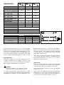
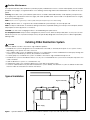
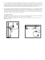
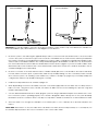
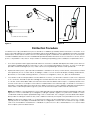
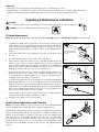
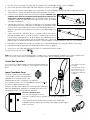
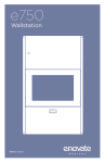
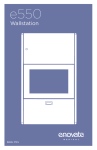
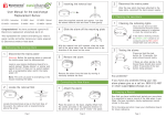
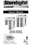
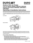
INSTALLATION MANUAL & OWNER’S GUIDE
Stainless Steel Ultraviolet Water Purification System
Buv-6
Buv-8
Buv-12
System Tested and Certified by
NSF International against NSF/
ANSI Standard 55 for Disinfection
Performance, Class B
55003.0612
Specifications
Item #
Model #
NSF Rated Flow Rate @ 16mJ/
cm2 @ 70% UVT - usgpm (l/min)
Flow Rate @ 16 mJ/cm2 @ 96%
UVT - usgpm (l/min)
Flow Rate @ 30 mJ/cm2 @ 96%
UVT - usgpm (L/min)
Flow Rate @ 40 mJ/cm2 @ 96%
UVT - usgpm (l/min)
Lamp Power (Watt)
Max. Current (Amp)
Inlet and Outlet Size NPT
Weight lbs (kg)
Operating Pressure psi (kpa)
Operating Temperature Range
Electrical
Electrical Plug
A inches (cm)
B inches (cm)
C inches (cm)
D inches (cm)
8880
Buv-6
8881
Buv-8
8882
Buv-12
5.5 (20.79)
7.8 (29.48)
12 (45.36)
12 (45.36)
18.8 (71)
26 (98.28)
6.4 (24.2)
10 (37.8)
13.9 (52.5)
4.8 (18.14)
7.5 (28.35)
10.4 (39.31)
21
0.4
1/2”
6 (2.67)
29
40
0.4
0.5
3/4”
1”
8 (3.57)
12 (5.36)
10-100 psi (69-689 kPa)
36 to 104° F (2 to 40° C)
100-240V - 50/60Hz
North American
Dimensions
17.32 (44)
2.5 (6.35)
4.33 (11)
21.65 (55)
23 (58.5)
2.5 (6.35)
4.33 (11)
27.56 (70)
31.5 (80)
2.5 (6.35)
4.45 (11.3)
36.61 (93)
B
A
C
D
Energy produced by the UV lamp has the ability to
destroy microorganisms that can live in water. There are
five major groups of microorganisms that are altered by
a specific spectrum of ultraviolet light: viruses, bacteria,
fungi, algae, and protozoa.
You have purchased one of the most technologically
advanced Ultraviolet Water Treatment System available
anywhere in the world. It has been designed with you, the
consumer, in mind. PURA® products are lightweight, easy
to use, and simple to maintain. PURA products will provide
you with healthy, clean drinking water for years to come.
When these microbes are exposed to the proper amount
of UV energy, their DNA structure is scrambled, and they
are unable to reproduce. Since the cell is now sterile or
dead, it is no longer a threat.
What is Ultraviolet?
Ultraviolet (UV) light from the sun has long been known for
its ability to deactivate microorganisms. However, it has
only been in recent years that equipment producing UV
light has been manufactured for residential use.
PURA Systems
PURA recommends that all UV systems include pre-filters
to process the water before it reaches the UV lamp. This
will ensure that maximum UV exposure is achieved.
WARNING:
NEVER LOOK DIRECTLY AT A LIGHTED UV LAMP.
ULTRAVIOLET RAYS CAN BE HARMFUL TO EYES.
PURA Ultraviolet Water Treatment Systems are designed
for indoor use only.
PURA Systems are designed to provide complete water
treatment in a compact, easy-to-use package. Please follow the directions in this Guide exactly when installing your
PURA System to ensure that it operates correctly.
UV energy is produced by low-pressure mercury vapor
enclosed in a tubular lamp. While a UV lamp resembles a
standard fluorescent lamp, it is similar in appearance only.
2
Safety Instructions
WARNING:
To guard against injury, basic safety precautions should be observed, including the following:
1. Read and follow all safety instructions.
2. CAUTION - Always disconnect power before servicing.
3. DANGER - To avoid possible electric shock, special care should be taken since water is present near electrical equipment. Unless a situation is encountered that is explicitly addressed by the provided maintenance and troubleshooting
sections, do not attempt repairs by yourself, refer to an authorized service facility.
4. Carefully examine the disinfection system after installation. It should not be plugged in if there is water on parts not
intended to be wet such as, the ballast or lamp connector.
5. Do not operate the disinfection system if it has a damaged cord or plug, if it is malfunctioning or if it has been dropped
or damaged in any manner.
6. Always disconnect water flow and unplug the disinfection system before performing any cleaning or maintenance
activities. Never yank the cord to remove from an outlet; grasp the wall plug and pull to disconnect.
7. Do not use this disinfection system for other than intended use (potable water applications). The use of attachments not
recommended or sold by the manufacturer/distributor may cause an unsafe condition.
8. Intended for indoor use only. Do not install this disinfection system where it will be exposed to the weather or to temperatures below freezing. Do not store this disinfection system where it will be exposed to the weather or to temperatures
below freezing unless all water has been drained from it and the water supply has been disconnected.
9. Read and observe all the important notices and warnings on the water disinfection system.
10. If an extension cord is necessary, a cord with a proper rating should be used. A cord rated for less Amperes or Watts
than the disinfection system rating may overheat. Care should be taken to arrange the cord so that it will not be tripped
over or pulled. Circuit breaker must not exceed power cord current rating (ie - 15A for North American NEMA 5-15P).
11. SAVE THESE INSTRUCTIONS
WARNING:
The UV light given off by this unit can cause serious burns to unprotected eyes and skin. Never look directly at an illuminated
UV lamp. When performing any work on the UV disinfection system always unplug the unit first. Never operate the UV system
while the UV lamp is outside of the UV chamber.
Note: The UV lamp inside the disinfection system is rated at an effective life of approximately 9000 hours. To ensure
continuous protection, replace the UV lamp annually.
Conditions For Use
Iron (Fe)
Hardness*
Turbidity
Manganese (Mn)
Tannins
UV Transmittance
< 0.3 ppm (0.3 mg/L)
< 7 gpg (120 mg/L)
< 1.0 NTU
< 0.05 ppm (0.05 mg/L)
< 0.1 ppm (0,1 mg/L)
> 75%**
*Where total hardness is less than 7 gpg, the UV unit should operate efficiently provided the quartz
sleeve is cleaned periodically. If total hardness exceeds 7 gpg, the water should be softened.
**Call customer service for recommendations on applications where UVT < 75%.
IMPORTANT: W
ater quality is extremely important for the optimum performance of your UV system. The following levels are
recommended for installation:
If your water chemistry contains levels in excess of those mentioned above, proper pre-treatment is recommended to correct these water problems prior to the installation of your UV disinfection system. These water quality parameters can be
tested by your local dealer, or by most private analytical laboratories. Proper pre-treatment is essential for the UV disinfection
system to operate as intended.
3
Routine Maintenance
It is important that any water treatment system be properly maintained to ensure consistent water quality. The information
provided on this page is of a general nature. See Cleaning, Disinfecting, and Routine Maintenance Procedure in this user
guide.
Cleaning: The inside of the system and the quartz sleeve should be cleaned bi-annually. Clean all parts (except the electronic parts) with soap and rinse them thoroughly with clean potable water. Dry the inside of the quartz sleeve thoroughly
before re-assembling system.
NOTE: Presence of iron or general poor water quality will require frequent inspection and cleaning.
O. Ring: Lubricate each .O - ring with a silicone based lubricant (Part # 92360) to ensure a proper seal.
NOTE: UV lamp should remain on at all times during use because; repeated starting of UV lamp shortens lamp life, and UV
lamp requires a warm up period of 1-2 minutes.
CAUTION: Use care when changing the filters to avoid breaking the quartz sleeve.
UV Lamp Replacement: Lamps must be changed every twelve months. While UV lamps rarely burn out, they do lose their
disinfection power. Use only PURA UV lamps as they are specifically designed for the PURA system to deliver high quality
drinking water.
Installing PURA Disinfection System
CAUTION
Electronic ballast must be connected to a grounded receptacle.
• The disinfection system is designed to be mounted either horizontally or vertically at the point-of-use or point-of-entry
depending on the specific flow rate of the unit.
• The complete water system, including any pressure or hot water tanks, must be sterilized before start up by flushing with
chlorine (household bleach) to destroy any residual contamination
• For safety purposes, the disinfection system should be connected to a ground fault interrupt circuit.
• The disinfection system is intended for indoor use only, do not install disinfection system where it may be exposed to the
outdoor weather.
• Install the disinfection system on cold water line only.
• If treating the entire house, install the disinfection system before any branch lines.
• A 5 micron sediment filter must precede the disinfection system. Ideally, the disinfection system should be the last treatment the water receives before it reaches the faucet.
Typical Installation
Bypass Assembly
5 Micron Sediment Filter
Softener
Water Supply
Figure 1 - Typical installation of disinfection system and the related components that may be used for the installation
4
1.The use of a bypass assembly is recommended in case the system requires ‘off-line’ maintenance. If this is the case,
it must be noted that the system will require supplementary disinfection of the distribution system if any water is used
during this bypass condition. In addition, during bypass, the water will NOT be disinfected until such time as the system
is sanitized and returned to service. Please refer to the complete disinfection procedure as outlined on page 7 of this
document. If the water is to be offline, the water must be boiled for twenty minutes prior to consumption.
2.Select a suitable location for the disinfection system and its related components. As it is recommended to install a
ground fault protected circuit (GFCI), make sure that this is taken into consideration prior to any installation. The system
can either be installed vertically (inlet port at the bottom) (Figure 1A), or horizontally (Figure 1B), When selecting a mounting location, you must also leave enough space to allow for the removal of the UV lamp and/or quartz sleeve (typically
leave a space equal to the size of the reactor chamber itself).
Pre-Installation Instructions
The figure below shows the proper water flow for horizontal or vertical installation. Make certain that your unit and the
inlet and outlet pipes are in the right position for either horizontal or vertical installation
Minimum Clearance to
unit overall length
NOTE: when installing in horizontal direction, please make sure that UV chamber is on a slope to allow water to be
drained during servicing
Total Length of the UV System
Total Length of the UV System
Figure 1A
Figure 1B
5
Minimum Clearance to
unit overall length
Correct Installation
Incorrect Installation
IMPORTANT: For vertical installation, the inlet is at the bottom and the outlet is near the top of the disinfection chamber. For
horizontal installation, pay careful attention to the diagram for flow direction.
3.Mount the system to the wall using the supplied clamps. Various connection methods can be used to connect the water
source to the system, however union type connectors are recommended. The use of a flow restrictor device (included with
the system) is strongly recommended when installing your system in order to maintain the manufacturers rated flow rate.
The flow restrictor should be installed on the outlet port and is designed to be installed in one direction only. Ensure that the
flow of the water matches the flow direction as indicated on the flow restrictor (Figure 1C). DO NOT SOLDER CONNECTIONS
WHILE ATTACHED TO THE SYSTEM AS THIS COULD DAMAGE THE O-RING SEALS. Mount the countdown assembly to the UV
chamber and tighten the metal clamp.
4.Mount the controller on the wall, near the reactor chamber. Ideally place the controller above the reactor and away
from any water connection point, to prevent any water from potentially leaking onto the controller by means of a leak
at a connection point or a ‘sweating’ system. Make sure you allow for a ‘drip-loop’ (Figure 1D) on the lamp, and power
cord (prevents water from potentially entering the controller).
5Install the UV lamp and sleeve as outlined on pages 8-9.
6.When all plumbing connections are made, slowly turn on the water supply and check for leaks. The most likely cause for
leaks is from the o-ring seal. In case of a leak, shut water off, drain cell, remove the retaining nut, wipe the o-ring and
threads clean and re-install.
7.Once it is determined that there are no leaks, plug the system into the ground fault interrupter circuit, and check controller to ensure the system is operating properly. The controller is designed to detect both power to the system and lamp
illumination. Reset the countdown timer to 365 days. It is important to NEVER LOOK DIRECTLY AT THE GLOWING UV LAMP.
8.Allow the water to run through the chamber for 5-10 minutes prior to use to clear any air or dust that may be in the
reactor.
PLEASE NOTE: When there is no flow, the water in the cell will become warm, as the UV lamp is always on. To remedy this, run
a cold water tap anywhere in the house for a minute to flush out the warm water.
6
Clamps
flow restrictor
Countdown Timer Assembly
Drip Loop
Figure 1D
Figure 1C
Disinfection Procedure
UV disinfection is a physical disinfection process and does not add any potentially harmful chemicals to the water. As UV
does not provide a disinfection residual, it is imperative that the entire distribution system located after the UV be chemically
disinfected to ensure that the water is free from any bacteriological contaminants. The disinfection process must be performed immediately after the UV unit is installed and repeated thereafter whenever the UV is shut down for service, without
power, or inoperative for any reason. The procedure for sanitizing the plumbing system is readily accomplished as follows:
1.Shut off the upstream water supply that feeds water into the reactor chamber and depressurize water system. Remove
the pre-filter cartridge and fill the sump with 1-2 cups of household (5.25%) bleach (chlorine) - Do NOT use hydrogen
peroxide. At all times during the process, make sure the UV unit (and lamp) is turned on and operational!
2.Repressurize water system, open each faucet and allow cold water to run until you smell chlorine, shut the faucet off and
then repeat the process for each faucet, including hot water. You must ensure that all taps, including outside faucets,
dishwashers, shower heads, washing machines, connections to refrigerators, toilets, etc., pass chlorinated water.
3.Once all the locations have passed the chlorine disinfection solution, you will need to leave the solution sit for a period
of 20 - 30 minutes. Reinstall the pre-filter cartridge into the filter and then flush the chlorine solution from the system until
no chlorine smell is detectable. Make sure that each fixture that was disinfected in step 2 is completely flushed of the
chlorine solution as the consumption of this water is not advised due to the extremely high concentration of chlorine. It is
important to remember that in the event that a UV is briefly shut down for routine cleaning or during power interruptions
where water could have passed through the system, the aforementioned procedure must also be followed.
Note A: The addition of chlorine (bleach) to a hot water tank that has in the past been fed with untreated raw water with
high levels of other contaminants (iron, manganese, hydrogen sulphide, organics, etc.) will result in oxidation of these
contaminants and may require repeated flushing of the hot water tank. This contingency must be dealt with independently under the startup procedure for any other conditioners that may form a part of the pre-treatment for the UV unit.
Note B: The above procedure (Steps 1 to 3) will result in a massive chlorine residual far in excess of the 0.5 to 1.0 mg/L
typically present in municipally chlorinated water and of a magnitude consistent with the minimum 50 mg/L chlorine
solution recommended for the disinfection of distribution systems known to be contaminated. Do not consume water
until complete system has been flushed.
7
OPERATION
• Always disconnect power before performing any work on the disinfection system.
• Regularly inspect your disinfection system to ensure that the power indicators are on and no alarms are present.
• Replace the UV lamp annually (or biannually if seasonal home use) to ensure maximum disinfection.
Operating & Maintenance Instructions
CAUTION
Prior to performing any work on the disinfection system, always disconnect the power supply first.
WARNING: DO NOT USE WATER DURING THIS PROCEDURE
UV Lamp Replacement
NOTE: RESET LAMP LIFE TIMER AFTER LAMP REPLACEMENT (see page 9) Refer to www.lamprecycle.org for lamp disposal
1.To replace the lamp, there is NO need to disconnect the system from the
water supply. DO NOT USE WATER DURING THIS PROCEDURE. Lamp replacement is a quick and simple procedure requiring no special tools. The UV
lamp must be replaced after one year in order to ensure adequate disinfection.
2.Disconnect main power source and allow the unit to power down for 30
seconds.
3. Unscrew the strain relief from the unit as shown in picture A.
4.Pull the lamp cord slowly away from the chamber and disconnect the
lamp from the cord. Do not twist the lamp from the connector, simply slide
the two apart. Avoid touching the lamp on the glass portion. Handling the
lamp at the ceramic ends if acceptable, however if you must touch the
lamp glass, please use gloves or a soft cloth. See picture B.
Strain relief
Use 15/16” wrench
if strain relief fitting
is tight
A
Lamp
connector
5.
Fully remove the lamp from the reactor chamber being careful not to
angle the lamp as it is removed from the chamber. If the lamp is removed
on an angle,pressure will be applied on the inside of the quartz sleeve,
causing the sleeve to fracture. See picture C.
UV lamp
6.To install a new lamp, first remove the lamp from its protective packaging,
again being careful not to touch the lamp glass itself. Carefully insert the
lamp into the reactor vessel (actually inside the quartz sleeve) . Insert the
lamp fully into the chamber leaving about two inches of the lamp protruding from the chamber. Next, attach the connector to the UV lamp. Ensure
the connector is fully seated onto the UV lamp.
B
7.Slide the lamp slowly through the aluminum nuts till it is seated inside the
chamber and screw the strain relief back in to place.
C
8. Plug the power supply to the control module.
Quartz Sleeve Replacement and Cleaning
NOTE: for first time installation of the UV system, it is recommended that quartz
sleeve is installed in the horizontal position to better sealing purposes.
Mineral deposits and sediment may accumulate on the quartz sleeve decreasing the UV energy detected. Good maintenance of filtration equipment will
reduce the accumulation of residues. If necessary, remove the quartz sleeve
and clean with a commercially available scale remover (CLR, Lime-Away,
etc.) and a lint free cloth. Repeat the process as often as necessary to keep
the quartz sleeve clean. Be sure to remove all traces of cleaning fluid from the
sleeve before it is reinstalled in the reactor (be sure not to allow liquid inside the
sleeve).
8
D
1. First remove the UV lamp by following steps as outlined in the “Lamp Replacement” section on page 8.
2. Shut off the upstream water supply that feeds water into the reactor chamber.
3. Shut off the downstream water supply. If your system does not have a separate downstream valve, simply open a downstream faucet to release any pressure that may be built-up in the system.
4. Unscrew the two aluminum nuts from the reactor chamber. CAUTION: Care
should be taken when unscrewing the bottom aluminum nut, otherwise the
quartz sleeve could fall and break. Place a small pail under the reactor
chamber to catch any water that may leak from the system (if installed
vertically). See picture E.
5. Carefully remove the two o-rings from the aluminum nuts. Grasp the quartz
sleeve and fully remove from the reactor chamber. As with the lamp, make
sure the sleeve is removed from the reactor chamber being careful not to
angle the sleeve as it is removed from the reactor to avoid breakage. See
picture F.
Aluminum nut
E
O-ring
Quartz sleeve
6. Clean the sleeve as outlined in above, or replace with a new sleeve.
Reinstall the quartz sleeve. To install the sleeve, carefully insert the sleeve
G
into the reactor chamber (do not drop). Install the other side aluminum nut
and o-ring once the sleeve reaches the other end. Make sure to clean and
lubricate (silicone release grease part # 92360) the o-ring. Discard the o-ring and replace it with new one if required.
7. Reinstall the other aluminum nut with o-ring (make sure to clean and lubricate the o-ring, also replace if necessary)
8. Reinstall the lamp as outlined in the “lamp replacement” section on page 8.
9. Slowly turn on the water and pressurize the reactor to verify that there are no leaks.
10. Reconnect to power source.
NOTE: If the system is put on a temporary bypass or if it becomes contaminated after the disinfection system, it will be necessary to shock the system with household bleach for a full 20 minutes before resuming the use of the water.
Control Box Operation
The control box is a dual voltage 115V/230V, 50Hz/60Hz. Make sure
the power cord of the control box is connected to GFCI receptacle.
LED is GREEN when lamp
is working
Item # 8880
Model # Buv-6
Description: Sterilizer, UV, Buv-6,
100V/240V, 50Hz/60 Hz
Lamp Countdown Timer
Serial Number: WGXXXXX
Date of Manufacture: MM-DD-YY
Box 1 of 1
Qty 1
WaterGroup Companies Inc.
Regina, SK Cambridge, ON
Fridley, MN
Made in China
Tested and Certified According
to ANSI/NSF Standard 55 Class B
7
75600 47242
NO Recycling
6
The lamp countdown timer keeps track
of the number of days of lamp has been
replaced since. The lamp needs to be
replaced after a year (or 365 days) of its operation.
LED is RED when lamp is
NOT working. The control box also sounds an
audible alarm during this
condition
The countdown timer works on a LR44 battery cell which can run
the timer for approximately five years.
When the 365 days have expired, the screen will start to blink and
alarm an audible beep. Replace the UV lamp (see instructions in
“lamp replacement” section) and reset the timer.
Reset the Countdown Timer
Press the reset the button once to
reset the countdown timer to 365 days. The 365 days will appear on the
screen
The countdown timer can also be removed from the holder and
installed in remote location with the help of the magnet location at the
back of the timer.
9
Reset Button
Troubleshooting
PROBLEM
1. Pressure Drop
CAUSE
CORRECTION
A. Sediment pre-filter clogged
A.Replace filter cartridge with appropriate 5
micron cartridge.
Note: check source water supply as fluctuations
may occur in source pressure
B. Flow regulator will result in pressure drop when
approaching full flow.
B. Flow regulator
2. High Bacteria Counts
A. Quartz sleeve is stained or dirty
B. Change in feed water quality
C. C
ontamination in water lines after UV
system
ossible break-through of sediment
D. P
through pre-filter
A.Clean sleeve with scale cleaner and eliminate source of staining problem (ie. soften
hard water, see page 5-6).
B. Have source water tested to ensure that
water quality is still within allowable limits for
this system.
C. It is imperative that effluent water stream be
shocked with chlorine (bleach) before water
leaves UV system - disinfection system must
have a bacterial free distribution system to
work effectively (see page 4).
D. Have source water tested for turbidity - may
need stepped filtration in order to catch all
sediment entering water system (20 micron
filter followed by UV system).
3. H
eated Product
Water
A. C
ommon problem caused by infrequent use of water
A.Run water until it returns to ambient temperature.
4. Water Appears Milky
A. Caused by air in the water lines
A.Run water until air is purged.
5. Unit Leaking Water
A. P
roblem with o-ring seal on gland
nuts
A.Ensure o-ring is in place, check for cuts or
abrasions, clean o-ring, moisten with water/
lubricant and re-install, replace if necessary.
B. Check location of disinfection system and
control humidity.
B. C
ondensation on reactor chamber
caused by excessive humidity and
cold water
C. Inadequate inlet/outlet port connections
C. C
heck thread connections, reseal with
Teflon® tape and re-tighten.
6. S ystem Shutting Down
Intermittently
A. Interrupted power supply
A.Ensure system has been installed on its own
circuit, as other equipment may be drawing
power away from UV (ie. pump or fridge).
UV system should not be installed on a circuit
which is incorporated into a light switch.
7. L amp Failure Alarm
On - New Lamp
A. L oose connection between lamp
and connector
B. Moisture buildup in connector may
keep lamp and connector from making a solid connection
A.Disconnect lamp from connector and reconnect, ensuring that a tight fit is accomplished.
B. Eliminate chance of any moisture getting to
the connector and/or lamp pins.
10
Parts Breakdown — Buv Models
Item #
89573
89574
89575
89577
89578
89584
89579
89581
89582
89583
89570
89571
89572
89580
89576
89585
System Tested and Certified by
NSF International against NSF/
ANSI Standard 55 for Disinfection
Performance, Class B
Part Ref
2
2
2
3
5
6
7
8
8
8
9
9
9
10
11
12
Description
Quartz Sleeve, Buv-6
Quartz Sleeve, Buv-8
Quartz Sleeve, Buv-12
Chamber Nut, Lamp Entry, Threaded
O-Ring
Countdown Timer, c/w Bracket
Clip
Flow Control, 6 GPM, 1/2” NPT
Flow Control, 8 GPM, 3/4” NPT
Flow Control, 12 GPM, 1” NPT
Lamp, UV, Buv-6
Lamp, UV, Buv-8
Lamp, UV, Buv-12
Ballast
Strain relief
Chamber Nut, c/w Stopper Bottom
Qty
1
1
1
2
2
1
2
1
1
1
1
1
1
1
1
1
For UV Model
Buv-6
Buv-8
Buv-12
All Models
All Models
All Models
All Models
Buv-6
Buv-8
Buv-12
Buv-6
Buv-8
Buv-12
All Models
All Models
All Models
3
5
9
8
2
7
11
5
10
12
6
1
Performance Data Sheet
Item #
Model #
Supplier Item #
NSF Rated Flow Rate @ 16mJ/
cm2 @ 70% UVT - usgpm (l/min)
Inlet and Outlet Size NPT
Operating Pressure psi (kpa)
Operating Temperature Range
Electrical
8880
Buv-6
GN-6
8881
Buv-8
GN-8
8882
Buv-12
GN-12
5.5 (20.79)
7.8 (29.48)
12 (45.36)
1/2”
3/4”
10-100 psi (69-689 kPa)
36 to 104° F (2 to 40° C)
100-240V - 50/60Hz
1”
1Lamp life: 8000-9000 hours of operation approximate
12 months of continuous service
4General installation conditions and needs: Avoid touch-
ing the sides of the quartz sleeve and lamp, handle by
the ends only. Ultraviolet lamp and quartz sleeve are
easily damaged.
5General operation and maintenance: Quartz sleeve is
to be cleaned every 6-12 months and to be replaced
every 24 months. UV lamp is to be replaced every year.
While testing was performed under standard laboratory conditions, actual performance may vary.
This Class B system or component conforms to NSF/ANSI 55 for the supplemental bactericidal treatment disinfected public
drinking water or other drinking water that has been tested and deemed acceptable for human consumption by the state or local
health agency having jurisdiction. The system is only designed to reduce normally occuring non-pathogenic nuisance microorganisms. Class B systems are not intended for treatment of contaminated water.
The system and installation shall comply with applicable state and local regulations
11
PURA® Stainless Steel Ultraviolet
Water Purification Systems
LIMITED WARRANTY
Subject to the conditions and limitations described below, the manufacturer warrants its stainless steel ultraviolet
drinking water systems (“Product”) when installed in accordance with PURA® specifications, to be free from defects
in materials and workmanship under normal use within the operating specifications given in page 3 of this manual for
the following periods; Ultraviolet lamps and sensor probes to be free from defects in material and workmanship for a
period of one (1) year, reactor chamber for a period of seven (7) years and all remaining parts of the Product including
the control for a period of (2) years from the date of purchase with receipt as proof of purchase. This warranty shall
apply only to the original end-user of the Product.
If the Product or any warranted component is found defective, the manufacturer, at its sole option, will repair or
replace such Product or warranted component, or will refund all or a pro-rated portion of the Product’s purchase
price. You pay only freight for repaired or replaced parts from our factory and local dealer charges, including but not
limited to labor charges, travel and transportation expenses, and handling fees.
This warranty shall not apply to any part damaged by accident, fire, flood, freezing, Act of God, bacterial attack, filter
fouling and/or scaling, sediment, misapplication, neglect, alteration, installation, or operation contrary to our printed
instructions, or by use of accessories or components which do not meet PURA specifications. If the drinking water system is modified by anyone other than an authorized PURA dealer, the warranty shall be void.
ALL IMPLIED WARRANTIES, INCLUDING WITHOUT LIMITATION WARRANTIES OF MERCHANTABILITY AND FITNESS FOR
PARTICULAR PURPOSE, ARE LIMITED IN DURATION TO THE PERIOD SPECIFIED ABOVE FOR PRODUCT AND COMPONENTS
DESCRIBED IN THIS LIMITED WARRANTY.
As a manufacturer, we do not know the characteristics of your water supply. The quality of water supplies may vary
seasonally or over a period of time. Your water usage may vary as well. Water characteristics can also change if the
Product is moved to a new location. For these reasons, we assume no liability for the determination of the proper
equipment necessary to meet your requirements, and we do not authorize others to assume such obligations for us.
Further, we assume no liability and extend no warranties, expressed or implied, for the use of this product with a water
source that does not meet the Conditions For Use in the Installation Guide & Owner’s Manual.
THE MANUFACTURER’S OBLIGATIONS UNDER THIS WARRANTY ARE LIMITED TO THE REPAIR OR REPLACEMENT OF THE
FAILED PRODUCT OR COMPONENTS OR THE REFUND OF THE PURCHASE PRICE (AT WATERGROUP’S OPTION), AND WE
ASSUME NO LIABILITY WHATSOEVER FOR DIRECT, INDIRECT, INCIDENTAL, CONSEQUENTIAL, SPECIAL, GENERAL, OR OTHER
DAMAGES, WHETHER FROM CORROSION OR OTHER CAUSES.
Some states do not allow limitations on how long an implied warranty lasts, so the above limitation may not apply to
you. Similarly, some states do not allow exclusion of incidental or consequential damages, so the above limitations or
exclusions may not apply to you. This warranty gives you specific legal rights, and you may also have other rights, which
vary from state to state. Consult your authorized PURA Dealer for warranty and service information.
For parts or service, contact:
WATERGROUP INC.
WATERGROUP COMPANIES INC.
FRIDLEY, MN
REGINA, SK • CAMBRIDGE, ON
1-800-354-7867
1-877-288-9888
www.watergroup.com