1
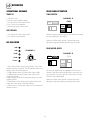
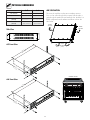
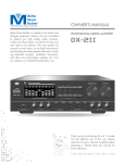
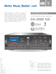
® ® OWNER'S MANUAL Passionate about Music PROFESSIONAL POWER AMPLIFIER Better Music Builder® is a leader in the Audio and Karaoke equipment industry. We are committed to offering you high quality audio products. Unlike any others brand, we deliver the best cost and value to you directly. For the latest update information including operation manuals, installation instructions, hook-up diagram and other new technologies updates etc. please visit us at our website w w w.B et terM usicB uil der.com. A-3 1200W@8ohm/3x400W A-4 1600W@8ohm/4x400W A SERIES PRO Power Amp A-3 3-Channel Power Amplifier POWER 0dB ® -3dB ® 3-CHANNEL POWER AMPLIFIER A-3 0dB CHANNEL 3 -3dB 0dB CHANNEL 2 -3dB -12dB -12dB -12dB -32dB -32dB -32dB Power -00 VOL 0dB Power -00 VOL 0dB Power CHANNEL 1 -00 VOL 0dB A-4 4-Channel Power Amplifier POWER 0dB ® -3dB ® 4-CHANNEL POWER AMPLIFIER A-4 0dB CHANNEL 4 -3dB 0dB CHANNEL 3 -3dB 0dB CHANNEL 2 -3dB -12dB -12dB -12dB -12dB -32dB -32dB -32dB -32dB Power -00 VOL 0dB Power -00 VOL 0dB Power -00 VOL 0dB Power CHANNEL 1 -00 VOL 0dB Thank you for purchasing this unit. To make full and effective use of this unit, please read this Owner's Manual carefully before operating it. Please retain this manual for future reference. w w w. B e t t e rM usi c B ui l d e r.c o m CONTENTS Intro Features Safety Connection Applications Amplifier Operating Dimensions Spec Troubleshooting Final Words Warranty INTRODUCTION................................................................................................................................................ 3 SYSTEM FEATURES............................................................................................................................................ 3 SAFETY INSTRUCTIONS.............................................................................................................................. 4~5 SPEAKER CONNECTION METHODS AND INFORMATION.................................................................... 6 SYSTEM APPLICATIONS................................................................................................................................... 7 • Connecting the Whole System for Small Format......................................................................................... 7 • Connecting the Whole System for Medium Format................................................................................... 8 • Connecting the Whole System for Large Format......................................................................................... 9 • Connecting The A-3 Output Source with 6-channel Mixer DX-6000 G2...................................... 10 • Connecting The A-4 Output Source with 3-channel Mixer DX-3000 G2....................................... 11 • Connecting The A-4 Output Source with 5-channel Mixer Dx-5000 G2....................................... 12 • Connecting The A-4 Output Source with 6-channel Mixer Dx-6000 G2...................................... 13 CONTROLS AND FUNCTIONS.................................................................................................................... 14 • Front Panel............................................................................................................................................................... 14 • Rear Panel................................................................................................................................................................ 14 OPERATION...................................................................................................................................................... 15 PHYSICAL DIMENSIONS............................................................................................................................... 16 SPECIFICATIONS............................................................................................................................................. 17 TROUBLESHOOTING............................................................................................................................... 18~19 FINAL WORDS TO USER............................................................................................................................... 19 WARRANTY...................................................................................................................................................... 20 AGENCY REGULATORY NOTICES............................................................................................................... 21 Notices CONTACT INFORMATION............................................................................................................................ 22 Contact Us 2 INTRODUCTION Intro Features PROFESSIONAL POWER AMPLIFIER The wait is over! The much anticipated stereo power amplifier from Better Music Builder has arrived! And it comes in two models: A-3 and A-4. A-3 is a 3-Channel and A-4 is a 4-Channel power amplifier. If you’re really looking for something to bring life to your party, bring this along and you’ll have a blast! A Series is equipped with the following distinguished features: Models: A-3 A-4 This new series is designed by the best minds here in Better Music Builder to make this the most efficient, most durable, and of course the best designed amplifier ever. When you’re using the best components and the most advanced technology, cutting the total weight wasn’t that difficult. And to officially make this the most portable amplifier, we’ve included front handles so you can lug the machine with ease. • 3-Channel and 4-Channel power amplifier • Sleek aluminum chassis • Signal level indicator for each channel • Link and Alone work mode • Power overload protection • Sophisticated Turbo-Cooling System helps extend life • Variable fan speed is automatically adjusted by temperature • Anti-dust ventilation grill • Front handles for portability • Gain has two settings: 32dB and 0.775V • Inputs: 3 or 4 XLR audio inputs • Outputs: 3 or 4 dual-banana audio outputs Considering how much power the A Series can bring, it needs a sophisticated cooling system. That’s where the patented Turbo-Cooling System from Better Music Builder comes in. Using the new technology, the system aligns the amplifier’s massive heat sinks to provide maximum cooling. Also, the fan speed is programmed to vary automatically based on temperature. What all this means is that the system extends the life of power transistors by maintaining safe internal temperatures. A-3 Front View POWER THIS AMPLIFIER INCLUDES THE FOLLOW: 0dB ® -3dB 0dB CHANNEL 3 -12dB ® 3-CHANNEL POWER AMPLIFIER Power -3dB CHANNEL 2 -12dB -32dB A-3 0dB VOL 0dB Power -3dB CHANNEL 1 • Power Amplifier: 1 pc • Instructional Manual: 1 pc • Warranty & Registration Card: 1 pc -12dB -32dB -00 -32dB -00 VOL 0dB Power -00 VOL 0dB A-3 Rear View FUSE MODEL: A-3 SIGNAL INPUT TERMINAL CALIFORNIA, UNITED STATES OF AMERICA E-mail: [email protected] www.BetterMusicBuilder.com ENGINEERED AND DESIGN IN U.S.A. CAUTION: TURN OFF AMPLIFIER BEFORE CHANGING THIS SWITCH CHANNEL 1 GAIN CHANNEL 2 GAIN LINK ALONE CHANNEL 3 360120720400 GAIN LINK ALONE 0.775V 0.775V 0.775V 32dB 32dB 32dB AC-POWER SERIAL NO. CHANNEL 1 CHANNEL 2 CHANNEL 3 AC 120V 60Hz CAUTION RISK OF ELECTRIC SHOCK DO NOT OPEN WITHOUT AUTHORIZATION TO REDUCE THE RISK OF ELECTRIC SHOCK, DO NOT REMOVE COVER. NO USER SERVICEABLE PARTS INSIDE REFER SERVICING TO QUALIFIED SERVICE PERSONNEL. CAUTION: SPEAKER CONNECTION WITH 8ohm MIN IMPEDANCE SPEAKER OUTPUT TERMINAL SAFETY MARK 029611-28 USA 120798-1 A-4 Front View POWER 0dB ® -3dB 0dB CHANNEL 4 -3dB -12dB ® 4-CHANNEL POWER AMPLIFIER Power 0dB CHANNEL 3 -12dB -32dB A-4 VOL 0dB Power -3dB 0dB CHANNEL 2 -12dB -32dB -00 VOL 0dB Power -3dB CHANNEL 1 -12dB -32dB -00 -32dB -00 VOL 0dB Power -00 VOL 0dB A-4 Rear View FUSE MODEL: A-4 SIGNAL INPUT TERMINAL CALIFORNIA, UNITED STATES OF AMERICA E-mail: [email protected] www.BetterMusicBuilder.com ENGINEERED AND DESIGN IN U.S.A. CAUTION: TURN OFF AMPLIFIER BEFORE CHANGING THIS SWITCH CHANNEL 1 GAIN CHANNEL 2 GAIN LINK ALONE CHANNEL 3 GAIN LINK ALONE SYSTEM FEATURES CHANNEL 4 360120725500 GAIN LINK ALONE 0.775V 0.775V 0.775V 0.775V 32dB 32dB 32dB 32dB AC-POWER SERIAL NO. CHANNEL 1 CHANNEL 2 CHANNEL 3 CHANNEL 4 AC 120V 60Hz CAUTION RISK OF ELECTRIC SHOCK DO NOT OPEN WITHOUT AUTHORIZATION CAUTION: SPEAKER CONNECTION WITH 8ohm MIN IMPEDANCE TO REDUCE THE RISK OF ELECTRIC SHOCK, DO NOT REMOVE COVER. NO USER SERVICEABLE PARTS INSIDE REFER SERVICING TO QUALIFIED SERVICE PERSONNEL. SPEAKER OUTPUT TERMINAL SAFETY MARK 029611-28 USA 120798-1 3 Safety A. The power-supply cord or the plug has been damaged; or SAFETY INSTRUCTIONS B. Objects have fallen, or liquid has spilled into this product; or Please visit our website at BetterMusicBuilder.com for the most updated information, corrections on errors and changes in this manual. You may also contact us at toll free at 1-800-318-2218. C. This product has been exposed to rain; or D. This product does not appear to operate normally or exhibits a marked change in performance; or E. This product has been dropped, or its chassis has been damaged. RISK OF ELECTRIC SHOCK DO NOT OPEN CAUTION: TO REDUCE THE RISK OF ELECTRIC SHOCK DO NOT REMOVE COVER (OR BACK) NO USER-SERVICEABLE PARTS INSIDE REFER SERVICING TO QUALIFIED PERSONNEL 13. Servicing: The user should not attempt to service this product beyond those means described in this operating manual. All other servicing should be referred to the Service Department. 1. Read Instructions: All the safety and operation instructions should be read before this product is operated. 14. To prevent electric shock, do not use this polarized plug with an extension cord, receptacle or other outlet unless the blades can be fully inserted to prevent blade exposure. 2. Retain Instructions: The safety and operating instructions should be kept for future reference. 3. Warnings: All warnings on this product in these operating instructions should be followed. 15. Grounding or Polarization: Precautions should be taken so that the grounding or polarization means of this product is not defeated. 4. Follow Instructions: All operating and other instructions should be followed carefully. 16. Power Precaution: Unplug this product during lightning storms or when unused for long periods of time. Note that this product is not completely disconnected from the AC power source when the power switch is in the OFF position. 5. Water and Moisture: This product should not be used near water, for example, near a bathtub, washbowl, kitchen sink, laundry tub, in a wet basement, near a swimming pool, swamp or salivating St. Bernard dog, etc. 17. This machine does not exceed the Class A/Class B (whichever is applicable) limits for radio noise emissions from digital apparatus as set out in the radio interference regulations of the US Department of Communications. 6. Cleaning: Clean only with a dry cloth. 7. Ventilation: This product should be situated so that its location or position does not interfere with its proper ventilation. For example, the Component should not be placed on a bed, sofa, rug, or similar surface that may block any ventilation openings, or placed in a built-in installation such as a bookcase or cabinet that may impede the flow of air through ventilation openings. AC-POWER SOURCES This set should be operated only from the type of power source indicated on the marking label. If you are not sure of the type of electrical power supplied to your home, consult your dealer or local power company. For those sets designed to operate from battery power, or other sources, refer to the operating instructions. 8. Heat: This product should be stayed away from heat sources such as radiators, or other devices producing heat. 9. Power Sources: This product should be connected to a power supply only of the type described in these operation instructions or as marked on this product. This unit is designed for use with 120V/60Hz AC. If the area where you live have different power source, you may need to use a transformer to convert to 120 Volts AC. 10. Power Cord Protection: Power supply cords should be routed so that they are not likely to be walked upon or pinched by items placed upon or against them. Please pay particular attention to cords plugs, convenience receptacles, and the point where they exit this product. 120V AC-POWER 11. Object and Liquid Entry: Care should be taken so that objects do not fall on, or liquids are not spilled into this product. POWER AC-POWER CORD INCLUDED 0dB ® -3dB ® 4-CHANNEL POWER AMPLIFIER 12. Damage Requiring Service: This product should be serviced only by qualified service personnel when: 4 A-4 0dB CHANNEL 4 -12dB -3dB 0dB CHANNEL 3 -12dB -32dB Power VOL 0dB Power -3dB 0dB CHANNEL 2 -12dB -32dB -00 VOL 0dB Power -3dB CHANNEL 1 -12dB -32dB -00 -32dB -00 VOL 0dB Power -00 VOL 0dB OVERLOADING Do not place the set on an unstable cart, stand, tripod, bracket, or table. The set may fall, causing serious injury to a child or an adult and serious damage to the set. Use only a cart stand tripod, bracket, or table recommended by the manufacturer. Do not overload wall outlets, extension cords or convenience receptacles beyond their capacity, since this can result in fire or electric shock. For the set with a three-wire grounding type ac plug: This plug will only fit into a grounding-type power outlet. This is a safety feature. If you are unable to insert the plug into the outlet, contact your electrician to have a suitable outlet installed. Do not defeat the safety purpose of the grounding plug. 120V AC-POWER An appliance and cart combination should be moved with care. Quick stops, excessive force and uneven surfaces may cause the appliance and cart combination to overturn. POWER CHANNEL-A FREQ. VOLUME ANTENNA-A 5 10 15 20 -30 -25 -20 -15 25 -10 30 -5 35 40 0 PEAK 000.000 RF AF M MUTE H Z FREQ. DUAL CHANNEL VHF WIRELESS SYSTEM 5 -30 10 15 20 -25 -20 -15 25 30 -10 -5 35 40 0 PEAK 000.000 CNANNEL-A DISPLAY -3dB VOLUME 0dB CHANNEL 4 -12dB ® Power -3dB VOL 0dB Power -3dB 0dB -3dB ® A-4 0dB CHANNEL 4 -12dB -3dB VOL 0dB VOL 0dB Power -3dB CHANNEL 1 -32dB -00 Power VOL 0dB -00 Power VOL 0dB Power -3dB CHANNEL 1 -32dB -00 VOL 0dB Power -00 VOL 0dB POWER -3dB ® VOL 0dB Power A-4 0dB CHANNEL 4 -12dB -3dB 0dB CHANNEL 3 -12dB -32dB Power VOL 0dB Power -3dB 0dB CHANNEL 2 -12dB -32dB -00 VOL 0dB Power -3dB CHANNEL 1 -12dB -32dB -00 -32dB -00 VOL 0dB Power -00 VOL 0dB Do not place the electronic equipment directly under sunlight or close to the window. It may cause overheat on the electronic equipment by the sunlight. X Do not block the openings and vents in the cabinet which is designed for the ventilation of the electronic equipment. The blocking may cause overheat in the electronic equipment because of insufficient circulation of air, so it would damage the electronic equipment. -3dB CHANNEL 1 -12dB -32dB -00 0dB ® 4-CHANNEL POWER AMPLIFIER 0dB CHANNEL 2 -12dB -32dB -00 0dB -12dB -32dB -00 0dB CHANNEL 3 -12dB -32dB Power VOL 0dB CHANNEL 2 -12dB -32dB -00 HEATER ® 0dB -3dB -12dB -32dB -00 Power ANTENNA-B 0dB CHANNEL 3 -12dB -32dB A-4 Do not place the electronic equipment near heat sources such as stoves, radiators and heaters, etc. Placing the electronic equipment too near to these heat sources would result in damaging the equipment and causing fire. 4-CHANNEL POWER AMPLIFIER 0dB Do not transport the electronic equipment by yourself if its weight exceeds 70 pounds. It is recommended that two people work together to transport the equipment or by using hand truck and the like. Do not store the electronic equipment near water or area with moisture such as bathroom, kitchen sink, laundry area and swimming pool, etc. POWER VOL CHANNEL 2 -3dB -12dB -32dB -00 Power M MUTE H Z CNANNEL-B DISPLAY 0dB ® 4-CHANNEL POWER AMPLIFIER 0dB CHANNEL 3 -3dB -12dB -32dB A-4 CHANNEL-B RF AF POWER 0dB CHANNEL 4 -3dB -12dB ® Do not place the electronic equipment onto the unstable table or stand. It is because it would fall easily from the unstable table or stand, so it may cause accident including personal injuries and damage the equipment. Please follow our instructions to install the equipment, or you may hire a professional technician to handle the installation for safety purpose. POWER 0dB ® 4-CHANNEL POWER AMPLIFIER -32dB -00 VOL 0dB Power -00 VOL 0dB POWER 0dB ® -3dB ® 4-CHANNEL POWER AMPLIFIER 5 A-4 0dB CHANNEL 4 -12dB -3dB 0dB CHANNEL 3 -12dB -32dB Power VOL 0dB Power -3dB 0dB CHANNEL 2 -12dB -32dB -00 VOL 0dB Power -3dB CHANNEL 1 -12dB -32dB -00 -32dB -00 VOL 0dB Power -00 VOL 0dB Connection SPEAKER CONNECTION METHODS AND INFORMATION CONNECTOR INFORMATION METHODS OF SPEAKER CONNECTION Balanced XLR Connectors 1. Insert Type (Poor Connection) Hot (+) Cold (-) Shield (Ground) XLR Pin 2 Pin 3 Pin 1 TRS Tip Ring Shield SPE AK 2 SHIELD HOT ERS GOOD NO GOOD MALE COLD 3 1 2. Single Banana Plug Type (Better Connection) SHIELD 1 SPE AK FEMALE COLD 3 HOT ERS 2 SHIELD 1 3 COLD 2 HOT 3. Double Banana Plug Type (Standard Connection) Balanced 1/4” TRS Plug RING SLEEVE SPE AK SLEEVE RING TIP ERS TIP RING (COLD) TIP (HOT) SLEEVE (SHIELD) 3/4” 19 mm Unbalanced 1/4” TRS Plug SLEEVE SLEEVE TIP Either banana plug or insert type can be used to connect the unit to speakers. Be sure to connect red (+) to red (+) and black (–) to black (–). Otherwise, the sound output would be 180° out of phase and distorted. TIP RING (COLD) TIP (HOT) SLEEVE (SHIELD) Follow these steps if you are inserting the wire directly into the speaker terminal. Speakon Connectors Source (INPUT) comes from the output source of the active/powered speaker while the bridge (OUTPUT) connects to the passive/non-powered speaker. 1. Strip off the vinyl covering and twist the tip of the wire core. 2. Loosen the knob and insert the wire core into the terminal hole. 3. Tighten the knob to fix the wire core in place. + 8 4 – 2 2– 1+ 2+ 1– Do not allow the wire core to protrude or touch other terminals or wires. If the cores of differing wires touch, damage may result to your components. REFERENCE CONNECT 6 Applications SYSTEM APPLICATIONS CONNECTING THE WHOLE SYSTEM FOR SMALL FORMAT Use the Classic Series speakers such as CS-250 (8-inch woofer), CS-500 (10-inch woofer) and CS-812 G2 (12-inch woofer) and Oval Series speakers such as O-6 (6-inch woofer), and O-10 (10-inch woofer) for an area between 300 and 500 square feet. CS-812 G2 DFS-112 SUB DFS-306 CS-812 G2 ® CH AN NE 0dB B CH NE -12 dB -12 -32 dB AN NE L2 -12 -32 dB 0 -0 VOL dB er Pow 0dB 0 -0 VOL dB er Pow 0dB B 0dB -3d -32 L3 L1 0dB -3d CH 0dB B -3d AN 0 0 - VOL dB er Pow A-3 ® ® PO WE R 3-C HA NN EL PO W ER AM PL IFI ER 3-CHANNEL POWER AMPLIFIER A-3 MIXER DX-3000 G2 SOURCE % 88 AM S I A S 9:42 rity o Prio Aut &T ent AT inm erta Ent Set up ss ele Wir n ctio eo nne Co HD Vid t jec il Ma Pro ss ele Wir s rce nd KTV Pro sou e Re Sou Fre g up r sin ake Spe Gro t Sta sic t Mu por cal Sup re r Ca hni Tec me sto Cu al Voc ics on TV Lyr AUX [iPhone/iPod/MP3 PLAYER] DV D DVD PLAYER 7 VOD [PC/HITBOX] CONNECTING THE WHOLE SYSTEM FOR MEDIUM FORMAT Use the Classic Series speakers such as CS-612 G2 or CS-812 G2 (12-inch woofer) and Dynamic Fusion Series speakers such as DFS-206 (one 6.5-inch woofer) and DFS-306 (two 6.5-inch woofers) for an area between 1,000 and 2,000 square feet. CS-812 G2 DFS-112 SUB TOUCH SCREEN SONG SELECTOR DFS-306 CS-812 G2 ® Pa ssi on ate abo ut Mu sic DFS-206 CH AN NE 0dB B 0dB -3d CH AN NE AN NE CH AN NE dB L4 -12 -32 dB dB -12 -32 dB 0 -0 VOL dB er 0dB 0 -0 VOL dB er 0dB 0 0 - VOL dB er Pow 0dB B 0dB -3d -12 -12 -32 Pow 0dB B -3d -32 L3 L2 Pow 0dB B -3d CH L1 0 -0 VOL dB er Pow ® WE R 4-C HA NN EL PO DFS-206 A-4 ® PO W ER AM PL IFI ER 4-CHANNEL POWER AMPLIFIER A-4 PARALLEL SOURCE MIXER DX-6000 G2 AU X AUX-MUSIC VIDEO BG M BGM PLAYER DV VOD (PC/HITBOX) D DVD PLAYER 8 CONNECTING THE WHOLE SYSTEM FOR LARGE FORMAT MIXER DX-6000 G2 SOURCE AU X AUX-MUSIC VIDEO BG M BGM PLAYER DV VOD (PC/HITBOX) D DVD PLAYER SCREEN 3-CHANNEL POWER AMPLIFIER A-3 CH AN NE 0dB B CH AN NE AN NE dB -12 -32 L2 -12 -32 dB 0 -0 VOL dB er Pow 0dB 0 -0 VOL dB er Pow 0dB B 0dB -3d -12 -32 L3 dB L1 0dB -3d CH 0dB B -3d 0 -0 VOL dB er Pow A-3 ® ® PO WE R 3-C HA NN EL PO W ER AM PL IFI ER 4-CHANNEL POWER AMPLIFIER A-4 CENTER DFS-306 CH AN NE 0dB B AN NE CH AN NE dB AN NE L4 -12 -32 dB L3 -12 -32 dB -12 -32 dB 0 -0 VOL dB er Pow 0dB 0 -0 VOL dB er Pow 0dB B 0dB -3d CH 0 -0 VOL dB er Pow 0dB B 0dB -3d -12 -32 L2 L1 0dB -3d CH 0dB B -3d 0 -0 CENTER DFS-306 VOL dB er Pow A-4 ® ® PO WE R 4-C HA NN EL PO W ER AM PL IFI ER SUBWOOFER DFS-112 SUB SUBWOOFER DFS-112 SUB Use the Dynamic Fusion Series speakers such as DFS-912 (12-inch woofer), DFS-915 (15-inch woofer) and DFS-112 SUB (12-inch woofer) and Dynamic Fusion Series speakers such as DFS-206 (one 6.5-inch woofer) and DFS-306 (two 6.5-inch woofers) for an area between 1,000 and 3,000 square feet. HD VOCAL LOUDSPEAKER DFS-915 CENTER DFS-206 CENTER DFS-206 HD VOCAL LOUDSPEAKER DFS-915 9 CONNECTING THE A-3 OUTPUT SOURCE WITH 6-CHANNEL MIXER DX-6000 G2 WIRELESS MICROPHONE SUBWOOFER DFS-115 SUB SUBWOOFER DFS-115 SUB FUSE GROUP A VOD AUDIO OUTPUT VIDEO INPUT TERMINAL AUX DVD BGM Parallel with front L CENTER 1 RIGHT L 1 2 3 LEFT SUB 1 GROUP B 4 R AUDIO [XLR] OUTPUT AUDIO INPUT TERMINAL REAR MIC INPUT 500mA / 125V MODEL: DX-6000 G2 CALIFORNIA, UNITED STATES OF AMERICA E-mail: [email protected] www.BetterMusicBuilder.com ENGINEERED AND DESIGN IN U.S.A. R CAUTION RISK OF ELECTRIC SHOCK DO NOT OPEN WITHOUT AUTHORIZATION MIC 4 MIC 5 VOD DVD KOD BGM COMPOSITE VIDEO OUTPUT AC-POWER 360110513000 AUX 1 AUX 2 CENTER 2 VOCAL MONITOR LEFT RIGHT MAIN OUT [Balance Fader] SUB 2 BASS AC~120V 60Hz 20W REMOTE USB INPUT DX-6000 G2 REAR VIEW FUSE MODEL: A-3 SIGNAL INPUT TERMINAL CALIFORNIA, UNITED STATES OF AMERICA E-mail: [email protected] www.BetterMusicBuilder.com ENGINEERED AND DESIGN IN U.S.A. CAUTION: TURN OFF AMPLIFIER BEFORE CHANGING THIS SWITCH CHANNEL 1 GAIN 32dB CHANNEL 2 GAIN LINK ALONE 32dB CHANNEL 3 360120720400 GAIN LINK ALONE 32dB AC-POWER SERIAL NO. CHANNEL 1 CHANNEL 2 CHANNEL 3 AC 120V 60Hz CAUTION RISK OF ELECTRIC SHOCK DO NOT OPEN WITHOUT AUTHORIZATION CAUTION: SPEAKER CONNECTION WITH 8ohm MIN IMPEDANCE TO REDUCE THE RISK OF ELECTRIC SHOCK, DO NOT REMOVE COVER. NO USER SERVICEABLE PARTS INSIDE REFER SERVICING TO QUALIFIED SERVICE PERSONNEL. SPEAKER OUTPUT TERMINAL SAFETY MARK 029611-28 USA 120798-1 A-3 REAR VIEW This diagram gives you an idea of how to connect three speakers to the 3-Channel power amplifier. If it’s used in a bigger room that’s in excess of 1,000 square feet, you may need two other speakers acting as rear speakers. When doing so, a second 2-channel power amplifier is required. MAIN LEFT SPEAKER GROUP A 10 CENTER SPEAKER MAIN RIGHT SPEAKER GROUP A CONNECTING THE A-4 OUTPUT SOURCE WITH 3-CHANNEL MIXER DX-3000 G2 This is the 4-channel power amplifier connection diagram. If you’re using a third party mixer, make sure there’s enough audio outputs to connect to the 4-channel power amplifier. SUBWOOFER DFS-112 SUB WIRELESS MICROPHONE SERIAL NO.: AUDIO INPUT TERMINAL AUX INPUT SUB VIDEO INPUT TERMINAL AUX VOD DVD L AUDIO OUTPUT L 1 2 AUDIO (XLR) OUTPUT AUDIO (¼”) OUTPUT FUSE MODEL: DX-3000 G2 MICROPHONE INPUT CALIFORNIA, UNITED STATES OF AMERICA E-mail: [email protected] www.BetterMusicBuilder.com ENGINEERED AND DESIGN IN U.S.A. 115 AC-POWER 3 R R VOLUME AUX VOD DVD OUTPUT VIDEO MONITOR OUTPUT REC R MAIN 1 R L MAIN 2 L MIC 3 MIC 4 REMOTE INPUT CAUTION RISK OF ELECTRIC SHOCK DO NOT OPEN WITHOUT AUTHORIZATION AC~120V 60Hz 35W AC~220V 50Hz DX-3000 G2 REAR VIEW FUSE MODEL: A-4 SIGNAL INPUT TERMINAL CALIFORNIA, UNITED STATES OF AMERICA E-mail: [email protected] www.BetterMusicBuilder.com ENGINEERED AND DESIGN IN U.S.A. CAUTION: TURN OFF AMPLIFIER BEFORE CHANGING THIS SWITCH CHANNEL 1 GAIN 32dB CHANNEL 2 GAIN LINK ALONE 32dB CHANNEL 3 GAIN LINK ALONE 32dB CHANNEL 4 360120725500 GAIN LINK ALONE 32dB AC-POWER SERIAL NO. CHANNEL 1 CHANNEL 2 CHANNEL 3 CHANNEL 4 AC 120V 60Hz CAUTION RISK OF ELECTRIC SHOCK DO NOT OPEN WITHOUT AUTHORIZATION CAUTION: SPEAKER CONNECTION WITH 8ohm MIN IMPEDANCE TO REDUCE THE RISK OF ELECTRIC SHOCK, DO NOT REMOVE COVER. NO USER SERVICEABLE PARTS INSIDE REFER SERVICING TO QUALIFIED SERVICE PERSONNEL. SPEAKER OUTPUT TERMINAL SAFETY MARK 029611-28 A-4 REAR VIEW MAIN LEFT SPEAKER GROUP A MAIN RIGHT SPEAKER GROUP A MAIN LEFT SPEAKER GROUP B MAIN RIGHT SPEAKER GROUP B 11 USA 120798-1 CONNECTING THE A-4 OUTPUT SOURCE WITH 5-CHANNEL MIXER DX-5000 G2 WIRELESS MICROPHONE SUBWOOFER DFS-115 SUB RS-232 VOD INPUT CALIFORNIA, UNITED STATES OF AMERICA E-mail: [email protected] www.BetterMusicBuilder.com ENGINEERED AND DESIGN IN U.S.A. MODEL: DX-5000 G2 VIDEO INPUT AUX DVD AUDIO INPUT MIC EFFECTOR L RECORDING OUT L SUB L L L L L L L R R R R R R R REAR CENTER R 361111015500 FUSE1A AUDIO (XLR) OUTPUT DELAY REPEAT ECHO REAR MICROPHONE MODE R AUX VOD DVD VOD VIDEO OUTPUT RETURN SEND AUX 1 AUX 2 115 SAFETY MARK USA 020898-1 MICROPHONE INPUT OUTPUT VOLUME 029536-28 R MAIN 1 L AUDIO (¼”) OUTPUT R MAIN 2 MIC 3 L MIC 4 AC-POWER REMOTE INPUT CAUTION RISK OF ELECTRIC SHOCK DO NOT OPEN WITHOUT AUTHORIZATION SERIAL NO.: AC~120V 60Hz 35W AC~220V 50Hz DX-5000 G2 REAR VIEW FUSE MODEL: A-2 SIGNAL INPUT TERMINAL CALIFORNIA, UNITED STATES OF AMERICA E-mail: [email protected] www.BetterMusicBuilder.com ENGINEERED AND DESIGN IN U.S.A. CAUTION: TURN OFF AMPLIFIER BEFORE CHANGING THIS SWITCH CHANNEL 1 GAIN 32dB CHANNEL 2 360120719500 GAIN LINK ALONE 32dB AC-POWER SERIAL NO. CHANNEL 1 CHANNEL 2 AC 120V 60Hz CAUTION RISK OF ELECTRIC SHOCK DO NOT OPEN WITHOUT AUTHORIZATION TO REDUCE THE RISK OF ELECTRIC SHOCK, DO NOT REMOVE COVER. NO USER SERVICEABLE PARTS INSIDE REFER SERVICING TO QUALIFIED SERVICE PERSONNEL. CAUTION: SPEAKER CONNECTION WITH 8ohm MIN IMPEDANCE SPEAKER OUTPUT TERMINAL SAFETY MARK 029611-28 2-CHANNEL POWER AMP REAR VIEW FUSE MODEL: A-4 SIGNAL INPUT TERMINAL CALIFORNIA, UNITED STATES OF AMERICA E-mail: [email protected] www.BetterMusicBuilder.com ENGINEERED AND DESIGN IN U.S.A. CAUTION: TURN OFF AMPLIFIER BEFORE CHANGING THIS SWITCH CHANNEL 1 GAIN 32dB CHANNEL 2 GAIN LINK ALONE 32dB CHANNEL 3 GAIN LINK ALONE 32dB CHANNEL 4 360120725500 GAIN LINK ALONE 32dB AC-POWER SERIAL NO. CHANNEL 1 CHANNEL 2 CHANNEL 3 CHANNEL 4 AC 120V 60Hz CAUTION RISK OF ELECTRIC SHOCK DO NOT OPEN WITHOUT AUTHORIZATION CAUTION: SPEAKER CONNECTION WITH 8ohm MIN IMPEDANCE TO REDUCE THE RISK OF ELECTRIC SHOCK, DO NOT REMOVE COVER. NO USER SERVICEABLE PARTS INSIDE REFER SERVICING TO QUALIFIED SERVICE PERSONNEL. SPEAKER OUTPUT TERMINAL SAFETY MARK 029611-28 USA 120798-1 A-4 REAR VIEW MAIN LEFT SPEAKER GROUP A MAIN LEFT SPEAKER GROUP B MAIN RIGHT SPEAKER GROUP B MAIN LEFT SPEAKER GROUP B MAIN RIGHT SPEAKER GROUP A MAIN RIGHT SPEAKER GROUP B 12 USA 120798-1 CONNECTING THE A-4 OUTPUT SOURCE WITH 6-CHANNEL MIXER DX-6000 G2 WIRELESS MICROPHONE SUBWOOFER DFS-115 SUB SUBWOOFER DFS-115 SUB FUSE GROUP A VOD AUDIO OUTPUT VIDEO INPUT TERMINAL AUX DVD BGM Parallel with front L CENTER 1 RIGHT L 1 2 3 LEFT SUB 1 GROUP B 4 R AUDIO [XLR] OUTPUT AUDIO INPUT TERMINAL REAR MIC INPUT 500mA / 125V MODEL: DX-6000 G2 CALIFORNIA, UNITED STATES OF AMERICA E-mail: [email protected] www.BetterMusicBuilder.com ENGINEERED AND DESIGN IN U.S.A. 360110513000 R CAUTION RISK OF ELECTRIC SHOCK DO NOT OPEN WITHOUT AUTHORIZATION MIC 4 MIC 5 VOD DVD KOD BGM COMPOSITE VIDEO OUTPUT AC-POWER AUX 1 AUX 2 CENTER 2 VOCAL MONITOR LEFT RIGHT MAIN OUT [Balance Fader] SUB 2 BASS AC~120V 60Hz 20W REMOTE USB INPUT DX-6000 G2 REAR VIEW FUSE MODEL: A-4 SIGNAL INPUT TERMINAL CALIFORNIA, UNITED STATES OF AMERICA E-mail: [email protected] www.BetterMusicBuilder.com ENGINEERED AND DESIGN IN U.S.A. CAUTION: TURN OFF AMPLIFIER BEFORE CHANGING THIS SWITCH CHANNEL 1 GAIN 32dB CHANNEL 2 GAIN LINK ALONE 32dB CHANNEL 3 GAIN LINK ALONE 32dB CHANNEL 4 360120725500 GAIN LINK ALONE 32dB AC-POWER SERIAL NO. CHANNEL 1 CHANNEL 2 CHANNEL 3 CHANNEL 4 AC 120V 60Hz CAUTION RISK OF ELECTRIC SHOCK DO NOT OPEN WITHOUT AUTHORIZATION CAUTION: SPEAKER CONNECTION WITH 8ohm MIN IMPEDANCE TO REDUCE THE RISK OF ELECTRIC SHOCK, DO NOT REMOVE COVER. NO USER SERVICEABLE PARTS INSIDE REFER SERVICING TO QUALIFIED SERVICE PERSONNEL. SPEAKER OUTPUT TERMINAL SAFETY MARK 029611-28 USA 120798-1 A-4 REAR VIEW MAIN LEFT SPEAKER GROUP A MAIN LEFT SPEAKER GROUP B MAIN RIGHT SPEAKER GROUP B 13 MAIN RIGHT SPEAKER GROUP A Amplifier CONTROLS AND FUNCTIONS FRONT PANEL: 1 POWER SWITCH ON/OFF 6 CHANNEL-2 SIGNAL LEVEL LED INDICATOR 2 CHANNEL-4 SIGNAL LEVEL LED INDICATOR 7 CHANNEL-2 GAIN CONTROL 3 CHANNEL-4 GAIN CONTROL 8 CHANNEL-1 SIGNAL LEVEL LED INDICATOR 4 CHANNEL-3 SIGNAL LEVEL LED INDICATOR 9 CHANNEL-1 GAIN CONTROL 5 CHANNEL-3 GAIN CONTROL 10 ANTI-DUST VENTILATION GRILL 1 2 POWER 3 4 0dB ® -3dB ® 4-CHANNEL POWER AMPLIFIER A-4 5 6 0dB CHANNEL 4 -3dB 7 8 0dB CHANNEL 3 -3dB 0dB CHANNEL 2 -3dB -12dB -12dB -12dB -12dB -32dB -32dB -32dB -32dB Power -00 VOL 0dB Power -00 VOL 0dB Power 9 -00 VOL 0dB Power CHANNEL 1 -00 VOL 0dB 10 REAR PANEL: 11 LINK/ALONE MODE 14 FUSE: Housing for the power supply fuse. 12 GAIN SWITCH 15 AUDIO (XLR) INPUT 13 SPEAKER OUTPUT TERMINAL 16 AC-POWER CABLE 11 12 13 14 FUSE MODEL: A-4 SIGNAL INPUT TERMINAL CALIFORNIA, UNITED STATES OF AMERICA E-mail: [email protected] www.BetterMusicBuilder.com ENGINEERED AND DESIGN IN U.S.A. CAUTION: TURN OFF AMPLIFIER BEFORE CHANGING THIS SWITCH CHANNEL 1 GAIN CHANNEL 2 GAIN LINK ALONE CHANNEL 3 GAIN LINK ALONE CHANNEL 4 360120725500 GAIN LINK ALONE 0.775V 0.775V 0.775V 0.775V 32dB 32dB 32dB 32dB AC-POWER SERIAL NO. CHANNEL 1 CHANNEL 2 CHANNEL 3 CHANNEL 4 AC 120V 60Hz CAUTION RISK OF ELECTRIC SHOCK DO NOT OPEN WITHOUT AUTHORIZATION CAUTION: SPEAKER CONNECTION WITH 8ohm MIN IMPEDANCE TO REDUCE THE RISK OF ELECTRIC SHOCK, DO NOT REMOVE COVER. NO USER SERVICEABLE PARTS INSIDE REFER SERVICING TO QUALIFIED SERVICE PERSONNEL. SPEAKER OUTPUT TERMINAL SAFETY MARK 029611-28 15 USA 120798-1 16 14 Operating OPERATION OPERATIONAL GUIDANCE REAR PANEL OPERATION START UP GAIN SWITCH CHANNEL 2 1. Check the wires. 2. Use the correct amplifier voltage. 3. Turn the volume to the minimum level. 4. Turn On the power amplifier. 5. Adjust to the proper volume level. GAIN LINK ALONE 0.775V 32dB SHUT DOWN 1. Turn the volume to the minimum level. 2. Turn Off the power amplifier. Slide the switch to adjust the gain on the channel. Increasing the gain amplifies the input signal. LED INDICATOR Please turn off the system at least 3 minutes before any adjustment. Improper handling may damage the system. 0dB -3dB LINK/ALONE MODE CHANNEL 1 CHANNEL 2 -12dB Power GAIN LINK ALONE -32dB -00 VOL 0dB 0.775V 32dB 1. Every channel has a green power indicator. Turn On the machine and wait 5 seconds. The LED indicators will turn on after the system finish self-inspection. 2. 32dB indicator shows the channel has output signals. 3. 12dB indicator shows the channel has output power closed 10% of RMS. 4. 3dB indicator shows the channel has output power 50% higher than RMS. 5. 0dB indicator shows the channel reached its full power output. At this time, there will be clip distortion. 6. When power is On but any indicator is Off, it means the channel is broken. This series of amplifier has the capability to link two input channels. Slide the switch to LINK mode to connect the two input channels or switch to ALONE mode to have the input channels work independently. Please turn off the system at least 3 minutes before any adjustment. Improper handling may damage the system. 15 Dimensions PHYSICAL DIMENSIONS AIR VENTILATION MODEL A-3 A-4 NET WEIGHT 33.1 Lbs / 15 Kg 35.3 Lbs / 16 Kg SHIPPING WEIGHT 39.7 Lbs / 18 Kg 41.9 Lbs / 19 Kg DIMENSIONS (WxHxD) 19x3.5x17.9 in 48.2×8.8×45.5 cm 19x3.5x17.9 in 48.2×8.8×45.5 cm PACKING DIMENSIONS (WxHxD) 22.8x4.5x21.3 in 58x11.5x54 cm 22.8x4.5x21.3 in 58x11.5x54 cm This series of amplifiers use the same ventilation structure. First, cool air enters through the front panel. While inside, it goes through the transformer and enters the fan. And then it is finally compressed into the radiator and flows out from the side outlets. WARM AIR EXITS WARM AIR EXITS Side View A-3 Front View COOL AIR ENTERS (Front) ” 19 3 cm . 48 0d B CH AN N EL -3dB 0d B CH AN N EL 0d B CH AN N EL dB B we 0d 0 -0 VO dB -32d Po -3dB -12 -32d Po -12 B we -12 0d 0 -0 VO dB -32d Po -3dB 3 2 B we 1 0d 0 -0 VO B L r B L r B L r ” 5 m 1 2c . 8 3 ® ® PO W ER A-3 L IER NE IF AN AMPL 3-CH WER PO ” 3.5cm 8 8. PORTABLE SYSTEM A-4 Front View ” 19 3 cm . 8 4 CHANNEL-A CHANNEL-B RF AF FREQ. POWER 5 -30 POWER 10 15 -25 -20 20 -15 25 30 -10 -5 35 40 0 PEAK RF AF 000.000 M MUTE H Z VOLUME ANTENA-A FREQ. DUAL CHANNEL VHF WIRELESS SYSTEM CNANNEL-A DISPLAY 0dB 15 -25 -20 20 25 -15 30 -10 -5 35 40 0 PEAK M MUTE H Z 0dB CHANNEL 4 -3dB -12dB ® VOLUME 0dB CHANNEL 3 -3dB -12dB -32dB A-4 VOL 0dB -3dB VOL 0dB VOL CHANNEL 1 -12dB -32dB -00 Power ANTENA-B 0dB CHANNEL 2 -3dB -12dB -32dB -00 Power MICROPHONE TONE 10 000.000 CNANNEL-B DISPLAY ® 4-CHANNEL POWER AMPLIFIER 5 -30 -32dB -00 Power 0dB VOL Power -00 VOL 0dB M O D E A D JU S TA B L E UP TREBLE MID MIC. INPUT BASS CENTER SR MIC. VOLUME POWER 0d B CH AN -3dB 0d B CH AN N EL B CH AN N EL B CH AN N EL -12 dB -32d Po B we 4 -12 0d 0 -0 VO dB -32d Po B we r B L r ” 5 m 1 2c . 8 3 ® ® PO W ER A- 4 L IER NE IF AN AMPL 4-CH WER PO ” 3.5cm 8 . 8 16 -12 0d 0 -0 VO dB -32d Po -3dB 0d -3dB 3 B we r 2 -12 -32d Po -3dB 0d 0d 0 -0 VO dB B we 0 VO MIC 2 MIC 1 3 EXCITER MIC DOWN MEMORY MIC 2 4 AUDIO SUB LOW REAR VOL INPUT VOL EXCITER HIGH Hz 20 240 SUB FREQ MUSIC VOL 1 0d -0 MUSIC VOL 10 CDG DVD VOD 5 CHANNEL AUDIO VIDEO EFFECTS PROCESSOR MIC 1 N EL B L r B L Volume Volume Volume LIGHT B Channel-B Main Right Volume Channel-C Rear Left OFF CUP SIGNAL 0dB POWER LIGHT CUP SIGNAL 0dB POWER LIGHT CUP SIGNAL 0dB Channel-A Main Left Volume LIGHT CUP L ON SIGNAL 0dB POWER 5-CHANNEL POWER AMPLIFIER Channel-D Rear Right 0dB POWER CENTER POWER Spec SPECIFICATIONS A-3 POWER A-4 0dB ® 0dB CHANNEL 3 -3dB MODEL ® 3-CHANNEL POWER AMPLIFIER RATED POWER MAXIMUM OUTPUT VOLTAGE INPUT SENSITIVITY MAX GAIN (0.775V) THD (Total Harmonic Distortion) A-3 -12dB -3dB VOL 0dB Power -3dB 0dB ® CHANNEL 1 -3dB -12dB -32dB -00 POWER 0dB CHANNEL 2 -12dB -32dB Power ® -32dB -00 VOL 0dB Power -00 VOL 0dB 4-CHANNEL POWER AMPLIFIER A-4 0dB CHANNEL 3 -3dB 0dB CHANNEL 2 -12dB VOL 0dB Power -3dB CHANNEL 1 -12dB -32dB -00 -32dB -00 VOL 0dB Power -00 VOL 8ohm/40ms 500W x 3 8ohm/40ms 500W x 4 4ohm/40ms 800W x 3 4ohm/40ms 800W x 4 80 V (Vp/40ms) 1.41 V (32dB/X40) 37.3 dB <0.025% (1kHz, normal operating conditions) 10Hz~22kHz (-3dB, normal operating conditions) <+ / -15 Degrees (20Hz-20kHz, normal operating conditions) S/N RATIO > 110dB (1kHz, X40 (32dB), A-weighted) DAMPING > 300 (63Hz) MINIMUM LOAD IMPEDANCE Power 400W x 4 <+ / - 0.5dB (20Hz-20kHz, normal operating conditions) INPUT IMPEDANCE 0dB 8ohm/60s FREQUENCY RESPONSE CONVERSION RATE VOL 400W x 3 <0.075% (60Hz/7kHz 4:1, normal operating conditions) PHASE RESPONSE -3dB -12dB -32dB -00 8ohm/60s INTERMODULATION DISTORTION POWER BANDWIDTH 0dB CHANNEL 4 -12dB -32dB Power > 20V/us (10kHz Square Wave, X40 (32dB) gain) > 20k ohm (1kHz, balanced input) > 3.2 ohm (single channel) SEPARATION > 80dB (1kHz) COMMON MODE REJECTION > 80dB (1kHz) 17 0dB Troubleshooting TROUBLESHOOTING 1. NO SOUND: Power indicator is Off. 5. BAD AUDIO OR MICROPHONE SOUNDS REMEDY: REMEDY: • Check the AC Plug. Check the source of audio (CD, DVD) to see if it’s scratched. • Ensure that the AC outlet works by testing other devices. If too many amplifiers are used on one outlet, the building's circuit breaker may trip and shut off power. Check audio cables or microphone cables. Use a better audio cable or 3pin XLR microphone cable. • Check the overload switch located on rear panel. • An amplifier that keeps shutting off may have a serious internal fault. Turn it off, remove AC power, and have the amplifier serviced by a qualified technician. 6. THERE IS NO PICTURE REMEDY: Check to see if video sources are selected accordingly. 2. NO SOUND: The power indicator light is On but -32dB light (signal light) is Off. Check to see if plugged in the video cables are plugged in. Check TV or display monitor. REMEDY: If the POWER indicator LED is On and the fan is running, but the signal LEDs indicate no signal, check the input. Make sure the signal source is operating and try another input cable. Connect the source to another channel or amplifier to confirm its operation. 7. VIDEO IS FLICKERING REMEDY: Check to see if the AV cable is damaged. Check audio cables or microphone cables. Use a better AV cable. Use a better audio cable or 3pin XLR microphone cable. We recommend connecting videos to the TV or monitor directly for best results. Ensure microphone is On. Check the microphone volume. 8. POWER CAN NOT BE TURNED ON REMEDY: 3. 0dB (OVERLOAD INDICATOR) IS ON & SOUND IS ABNORMAL Check to see if unit is plugged in properly. Check power cable. REMEDY: Sound of music signal output amplitude is too high. The gain level is set too high. 9. PROTECTION FOR AUDIO/VIDEO EQUIPMENT Ensure the output connection is connected correctly and then reboot the machine. Before hooking up or disconnecting any audio/video equipment, turn off the power for all equipment. Otherwise, it may cause black spots to appear on the LCD or Plasma TV screen. 4. SIGNAL LED IS NOT RESPONDING TO SIGNAL LEVEL 10. AMPLIFIER SHUT DOWN/INTERFERENCE NOISE REMEDY: If the SIGNAL indicator is lighting normally, the problem may be between the amplifier and the speaker. Check the speaker wiring for breaks. Try another speaker and cable. CAUSE: The amplifier turned On but there is no music coming out from the speaker powered output channels. REMEDY: Ensure that the AC-power supply is connected to the correct voltage level according to your region. 18 Final Words 11. NOISE AND DISTORTION The engineering team of Better Music Builder has many years of experience in audio equipment design. The team constantly develops new audio technologies, designs innovative audio and karaoke equipment to suit your specific needs and provides you great ideas for home entertainment. When humming noise or displeasing sound appears, replace the supplied power cord with an AC power cord with a magnetic device as shown in the figure below. Our engineering team also designs audio equipment for commercial use by restaurants, coffee shops, churches, and school auditoriums, etc. If the commercial area for audio equipment installation exceeds 2,000 square feet, we highly recommend hiring audio professionals to handle the installation in order to avoid risks in breaking the equipment with improper installation and safety protection purposes. 3 prong to 2 prong adaptor 110V~120V FIGURE 1 We also provide educational and technical information on audio equipment and technologies. For example, we provide free installation diagrams to make it easier to connect the system. In addition, to get best connections for the sharpest image and sound quality, we provide hot tips for choosing the high quality type of A/V cable connections. Free information on audio equipment and technologies available for download from our website, w w w.B et terM usicB uil d er.com. Q u alit y Powe r Co rd: 105° C 3C/18AWG 30 0V FIGURE 2 NOTE In North America many families own satellite TVs, HD TVs and cable TV receivers. They may cause interference which affect both audio and video equipment. The power cord as shown in figure 2 may help eliminate the humming sound and enhance TV picture quality. Please do not remove the “Yellow Label” on the rear of the machine; otherwise, the warranty will be void automatically. We design it to protect your own safety. If repair and maintenance service is needed, Any form of please contact us directly or hire a tampering with this product, will void professional technician. To learn more the warranty. about the technical aspects, visit our website w w w.B et terM usicB uil d er.com and download the relevant information for review. 12. SOUND PROBLEM: No sound. REMEDY: SPEAK FINAL WORDS TO USER ERS Positive and negative of speaker wire are touching each other at the terminals. We recommend the usage of double banana plugs. Before hooking up the system, turn off the power on all machines including audio/video equipment and TV. Otherwise, it may damage the equipment, especially on the HDTV in which a spot might appeared on the TV screen. After hooking up the system, double check the audio/video connections to ensure that they are connected correctly. NOTE Sometimes, loose or poor quality cable would affect the microphone effects, picture quality, or even cause the machine to shut down suddenly. Again, thank you for choosing Better Music Builder. We hope you can make the best use of the machine and enjoy it for years to come. If you have any questions regarding our product, please feel free to contact us at w w w.B et terM usicB uil d er.com. 19 Warranty WARRANTY ONE-YEAR LIMITED WARRANTY FOR HOME USE EQUIPMENT ADDITIONAL NOTES: 1. Limited warranty for home use equipment is only valid in North America. Our one-year warranty covers both parts and labors. The warranty becomes effective from the date of your purchase for one year. 2. Limited warranty is valid only if you purchase our products from our authorized dealers (including both regular retailers and online retailers) in North America. If you choose to purchase our products from an authorized dealer, we will not provide any limited product warranty for you. To protect your limited product warranty, please purchase our products from one of our authorized dealers in North America near you. Our warranty only covers defects due to product defectiveness with free of defects in materials or workmanship. However, our warranty does not cover defects due to normal wears, damage in transit, improper use, abuse or failure to follow the proper instructions for maintenance. This warranty is void in the event of unauthorized repairs, alternations, modifications and removing of the product label. 3. Limited warranty is automatically void if the yellow label stating “No Warranty After Opening” is removed from the product. Please also note that our warranty does not cover any shipping cost for the return of defective products to us for inspection, repair and maintenance. Our warranty for Better Music Builder products can only be executed in North America. TO REGISTER YOUR WARRANTY Please fill out the warranty card that came with your unit, download or submit online warranty form. However, we need the invoice for your purchase in order to process this warranty. You may also register your warranty online. Please visit our website at w w w.b et termusicb uil d er.com. 90-DAY LIMITED WARRANTY FOR PUBLIC AND COMMERCIAL USE EQUIPMENT Our 90-day warranty applies to speakers, amplifiers, mixers and microphones for both public and commercial use such as restaurant, coffee shop, KTV nightclub, church and school, etc. It covers both parts and labors. The warranty becomes effective from the date of your purchase for 90 days. Our warranty only covers defects due to product defectiveness with free of defects in materials or workmanship. However, our warranty does not cover defects due to normal wears, damage in transit, improper use, abuse or failure to follow the proper instructions for maintenance. This warranty is void in the event of unauthorized repairs, alternations, modifications and removing of the product label. Please also note that our warranty does not cover any shipping cost for the return of defective products to us for inspection, repair and maintenance. Our warranty for Better Music Builder products can only be executed in North America. 20 Notices AGENCY REGULATORY NOTICES FEDERAL COMMUNICATIONS COMMISSION NOTICE your waste equipment at the time of disposal will help to conserve natural resources and ensure that it is recycled in a manner that protects human health and the environment. For more information about where you can drop off your waste equipment for recycling, please contact your local city office, your household waste disposal service or the shop where you purchased the product. These limits are designed to provide reasonable protection against harmful interference in a residential installation. This equipment generates, uses, and can radiate radio frequency energy and, if not installed and used in accordance with the instructions, may cause harmful interference to radio communications. However, there is no guarantee that interference will not occur in a particular installation. If this equipment does cause harmful interference to radio or television reception, which can be determined by turning the equipment off and on, the user is encouraged to try to correct the interference by one or more of the following measures: • Reorient or relocate the receiving antenna. • Increase the separation between the equipment and the receiver. • Connect the equipment into an outlet on a circuit different from that to which the receiver is connected. • Consult the dealer or an experienced radio or television technician for help. JAPANESE NOTICE JAPANESE POWER CORD NOTICE Modifications The FCC requires the user to be notified that any changes or modifications made to this device that are not approved may void the user’s authority to operate the equipment. JAPANESE MATERIAL CONTENT DECLARATION Cables Connections to this device must be made with shielded cables with metallic RFI/EMI connector hoods to maintain compliance with FCC rules and regulations. A Japanese regulatory requirement, defined by Specification JIS-C-0950, 2005, mandates that manufacturers provide Material Content Declarations for certain categories of electronic products offered for sale after July 1, 2006. MATERIALS DISPOSAL KOREAN NOTICE Disposal of this material can be regulated because of environmental considerations. For disposal or recycling information, contact your local authorities or the Electronic Industries Alliance (EIA) (http://www.eiae.org). RECYCLING PROGRAM DISPOSAL OF WASTE EQUIPMENT BY USERS IN PRIVATE HOUSEHOLDS IN THE EUROPEAN UNION The terms and availability of these programs vary by geography because of differences in regulatory requirements and local customer demand. This symbol on the product or on its packaging indicates that this product must not be disposed of with your other household waste. Instead, it is your responsibility to dispose of your waste equipment by handing it over to a designated collection point for the recycling of waste electrical and electronic equipment. The separate collection and recycling of 因为在当地的监管要求和客户的需求,这些条件和程序的情 况不同。 21 Contact Us CONTACT INFORMATION MAILING ADDRESS BE T TER M USI C BU I LD ER 2930 0 Kohoutek Way #150 Union Cit y, CA 94587 U.S.A. TELEPHONE NUMBERS USA Region USA Toll Fre e: 1-80 0 -318-2218 S ales & M arketing: 510 - 477-9955 Customer S er vice: 510 - 477-9955 FAX NUMBERS USA Region S ales & M arketing: 510 - 477-9922 Customer S er vice: 510 - 477-9922 WORLD WIDE WEB E-mail: [email protected] Website: www.bettermusicbuilder.com MAINTENANCE With proper maintenance and regular service, it would maintain the machine quality and prolong its life. We recommend you to print the following information clearly for future reference on maintenance and warranty. MODEL#_____________________INVOICE #_____________ DATE PURCHASED (MM/DD/YYYY)____________________ DEALER NAME______________________________________ CITY_____________ ST./PROV.______ZIP/P.C.____________ DEALER WEBSITE http://www.________________________ DEALER PHONE #___________________________________ DEALER E-MAIL______________________________________ 22 23 ® ® Unlike any others ... that’s cost & value for you Passionate about Music www.BetterMusicBuilder.com Thank you for purchasing this unit. To make full and effective use of this unit, please read this Owner's Manual carefully before operating it. Please retain this manual for future reference. 360120725500 Printed on 100% Recycled Paper Code: 20120701 Comments E-mail to [email protected] Copyright © 2012 Better Music Builder. All rights reserved. Legal trademark.