1
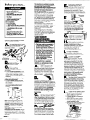
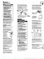
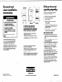
ROPER’”
Appliances
IMPORTANT:
Installer: Leave Installation Instructions with the appliance.
Homeowner: Keep Installation Instructions for future reference
Save Installation Instructions for local electrical inspector’s use.
Part No.3393136 Rev. A
Before you start...
Fire Hazard
Never install dryer up
against draperies or curtains
or on carpet.
. Keep any and all items from
falling or collecting behind
the dryer.
l
Replace all access panels
before operating dryer.
Failure to follow these
instructions could result in a
fire or explosion.
. If you smell gas:
1. Open windows.
2. Don’t touch electrical switches,
3. Extinguish any open flame.
4. Immediately call your gas
supplier.
. Do Not store or use gasoline or
other flammable vapors and
liquids in the vicinity of this or
any other appliance. The
fumes can create a fire hazard
or explosion.
l
Mark an X across the letter or number
as you complete each step.
You need these tools to inst
to install the dryer...proper
installation is your responsibility.
C
Make sure you
n have everything
necessary for proper installation.
You’ll need:
requirements: some
l To meet code
codes keep from or limit installation of
clothes dryers in garages, closets,
mobile homes and sleeping quarters.
(Check with your local building
inspector]
Important: observe all governing
codes and ordinances.
l To check
utilities: proper gas and
l
electric supply connections should
be available.
To check exhaust requirements:
a four inch metal exhaust duct is
required.
LOCATION
This appliance is suitable for mobile
home installations. The installation of
the dryer must conform to the
Manufactured Home Construction and
Safety Standard, Title 24 CFR, Part 3280
(formerly the Federal Standard for
Mobile Home Construction and Safety,
Title 24, HUD,Part 280).
For mobile home use, this appliance
MUST be fastened to the floor and
MUST be exhausted to the outside.
Order Mobile Home Installation Kit
No. 346765 from your Whirlpool dealer.
Kit includes the necessary fastening
hardware and detailed installation
instructions.
Exhaust system hardware
is also available through your
Whirlpool dealer.
This installation must conform with
American National Standard, National
Fuel Gas Code ANSI 2223.1 - latest
edition, and all local codes and
ordinances.
Input ratings shown on the rating
plate (serial tag) are for elevations up
to 2,000 feet. For elevations above
2,000 feet, ratings should be reduced
at a rate of 4% for each 1,000 feet
above sea level.
Gas supply
requirements
Fire Hazard
. This dryer must be connected to
a regulated gas supply. Failure
to do so could cause highpressure gas release, resulting in
a fire or explosion.
l
Have the L.P. gas checked by a
qualified person before installing
the dryer. The L.P. gas supply
must not exceed a pressure of
13” water column.
l New flexible
tubing should be
used. Reusing old flexible
tubing might result in possible
leaks or fire hazard.
Failure to follow these instructions
may result in fire or explosion.
OBSERVEALL GOVERNING CODES
AND ORDINANCES
First make certain that this
dryer is equipped with
n
the correct burner for
the particular type of gas in the home.
Burner information will be found on
the rating plate in door well of the
appliance.
If this information does not
agree with the type of gas available,
see your dealer
A
B.
This dryer is equipped for use with
NATURAL GAS. It is certified by A.G.A. for
manufactured,
mixed and L-F?gases with
appropriate
conversion. No attempt shall
be made to convert the appliance from
the gas specified on the rating plate for
use with a different gas without consulting
the serving gas supplier. Conversion
must be done by a qualified service
technician. Gas conversion kit part
numbers are listed on the gas valve
burner base.
c.
Size: Must be large enough to fully
open dryer door. For recessed or closet
installation spacing see back cover
Support: The floor must be able to
support the appliance
weight of 175
pounds.
Level floor: Maximum floor slope
under dryer - 1 inch.
Protection from the weather: Proper
operation of dryer cycles requires
temperatures above 45” F, or the dryer
may not shut off when automatic cycles
are used.
PANEL A
Provide a gas supply line to
the dryer location. When
rigid pipe is used it should be ‘/2 inch IPS.
When acceptable
to the gas supplier,
3/einch approved tubing may be used
for lengths under 20 feet. For lengths
over 20 feet, larger tubing should be
used. Pipe joint compounds resistant to
the action of LP gas must be used.
The supply line sho?;jd be equipped
with a shut-off valve. This valve should
be located in the same room as the
dryer and should be in a location that
allows ease of opening and closing.
Do not block access to shut-off valve.
If the dryer is installed in a
confined area such as a
n bedroom, bathroom or closet, it
must be exhausted to the outside and
provision made for enough air for
combustion and ventilation. (Check
governing codes and ordinances.] Also
refer to the section of this instruction
covering Recessed or Closet Installations.
E
recommende
that flexible m
Association, be used for connecting
the appliance
to the gas supply line.
[The gas pipe which extends through
the lower rear of the appliance
has
3/~inch male pipe thread.]
rrgid pipe is used as a gas
n supply line, a combination
of pipe fittings must be used to obtain
an in-line connection to the dryer
H
Make sure the lower edges
n of the cabinet, plus the back
and bottom sides of the dryer
are free of obstructions to permit
adequate clearance of air openings
for combustion air See Recessed
Area Instructions, Panel B, for
minimum spacing requirements,
For ease of installation,
I n operation and servicing
(if ever needed] adequate space
should be provided around the dryer
J
A ‘/e inch NPT plugged
accessible
for test gage connection,
must be
installed immediately upstream of the
gas supply connection to the dryer
The dryer and its individual shut -off
valve must be disconnected
from the
gas supply piping system during any
pressure testing of that system at test
pressures in excess of 1/2psig (3.45 kPa).
The dryer must be isolated from the
gas supply piping system by closing its
individual manual shut-off valve during
any pressure testing of the gas supply
piping system at test pressures equal
to or less than 1/2psig (3.45 kPa).
n tapping,
Important: observe all governing
codes and ordinances.
K
The dryer shutoff valve and the
are located
behind the lower front access panel.
Open the access panel by pushing
down on the locking clips with a small,
flat-blade
screwdriver,
and pulling
panel forward. The clips are located
on top of the panel 3 inches in from
each side. The panel is hinged at the
bottom. Close the access panel after
servicing. Do Not operate the dryer
with the access panel open.
L
n wiring diagram
If dryer will not opera-te, check
the following to be sure that:
1. Electric supply is connected.
2. Fuse is intact and tight.
3. Door is closed.
4. Controls are set in a running or
“On” position.
5. Start button has been pushed
firmly or the power control lever
moved upward to start.
6. Gas shut-off valves are open both
on dryer and on supply lines.
n
Electrical
reaufrements
Electrical Shock Hazard
l Electrical
ground is required on
this appliance.
l Improper
connection of the
equipment-grounding
conductor can result in a risk of
electrical shock.
l Check
with a qualified
electrician if you are in doubt
as to whether the appliance is
properly grounded. Do Not
modify the power supply
cord plug. lf it will not fit the
outlet, have a proper outlet
installed by a qualified
electrician.
l
Do Not use an extension cord
wit this appliance. Such use
may result in a fire, electrical
shock or other personal injury.
. Do Not have a fuse in the
neutral or grounding circuit. A
fuse in the neutral or grounding
circuit could result in electrical
shock.
Failure to follow these instructions
could result in electrical shock or
other personal injury.
A 120 volt, 60 Hz, AC only, 15 or 20
Ampere fused electrical supply is
required. Time-delay fuse or circuit
breaker is recommended.
It is
recommended
that a separate
circuit serving only this appliance
be provided.
RECOMMENDED GROUNDING
METHOD
Electrical ground is required on this
appliance.
DO NOT, UNDER ANY CIRCUMSTANCES,
REMOVE THE POWER SUPPLY CORD
GROUNDING PRONG.
For your personal safety, this
appliance
must be grounded.
This
appliance
is equipped
with a power
supply cord having a 3-prong
grounding
plug.
To minimize possible
shock hazard, the
cord must be
plugged into a
mating 3-prong
grounding-type
wall receptacle,
’ \
grounded
in
3prong
grounding
accordance
with
Plug
the National
” $7 POWW
Electrical Code,
ANSl/NFPA 70 - latest
‘% SUPPlY
cord
edition, and all local codes
and ordinances.
If a mating wall
receptacle
is not available,
it is the
personal responsibility and obligation
of the customer to have a properly
grounded 3-prong wall receptacle
installed by a qualified electrician.
For added personal safety, using the
clamp and green-colored
copper wire
furnished, connect this separate
grounding wire (#I8 minimum] from the
external grounding connector on the
back of the appliance to a grounded
cold water pipe?
TEMPORARYGROUNDING METHOD
DO NOT, UNDER ANY
CIRCUMSTANCES, REMOVE THE
POWER SUPPLY CORD GROUNDING
PRONG.
THIS, HOWEVER,IS NOT
RECOMMENDED.
If changing and properly grounding
the wall receptacle is impossible and
where local codes permit (consult your
electrical inspector), a temporary
adapter may be plugged into the
existing 2-prong wall receptacle to
mate with the 3-prong power supply
cord.
PANEL B
Use Duct Tape to seal all joints.
If this is done, you must connect a
separate copper grounding wire (No.
18 minimum] to a grounded cold water
pipe’ by means of a clamp and then
to the external ground connector screw.
If the dryer is installed in a confined
area such as a bedroom, bathroom
Do not ground to a gas supply pipe
or hot water pipe. Do not connect to
electrical supply until appliance
permanently grounded.
n
\
is
‘Mmtol Cold Water
or
closet, it must be exhausted to the
outside and provision made for
enough air for combustion
and
ventilation.
(Check governing codes
and ordinances.)
Also refer to the
section of this instruction covering
Recessed and Closet Instructions.
Pi&
The Exhaust
Outlet is locate
at the bottom center
of the dryer back.
K
MUST BE TIGHT
v
must have metal continuity
to electrical
ground and not be
interrupted by plastic, rubber or other
electrically
insulating connectors [including
water meter or pump] without adding a
jumper wire at these connections.
Bumps on
grounding
clamp must
contact pipe.
The Exhaust Duct
can be routed up,
down, left, right or
straight out the
back of the dryer.
P
An Exhaust Hood should cap the
Fire/Health Hazard
Do Not use non-metal,
flexible duct.
0 Do Not use metal duct smaller
than four inches in diameter.
mDo Not use exhaust hoods with
magnetic latches.
BCheck that exhaust system is not
longer than specified. Exhaust
systems longer than specifted
will:
-Accumulate lint.
Shorten the life of the dryer.
-Reduce performance, resulting
in longer drying times and
increased energy usage.
Lailure to follow specifications
nay result in a fire.
l
DDo Not exhaust dryer into a
chimney, furnace cold air duct,
attic or crawl space, or any
other duct used for venting.
l Clean the exhaust
system every
other year.
l Do Not install flexible
duct in
enclosed walls, ceilings or floors.
4ccumulated lint could result in a
‘ire or cause moisture damage.
Exhaust the dryer outside to
prevent exposure to substances
in the gas fuels and combustion
which may be harmful to your
health.
The moisture and lint indoors
may cause:
- FIREHAZARD from lint
collected in dryer;
- Moisture damage to
woodwork, furniture, paint,
wallpaper, carpet, etc.
- House cleaning problems and
possible health problems.
Failure to follow these instructions
could result in fire damage or
personal injury.
exhaust duct to prevent exhausted air
returning into dryer The outlet of the
hood must be at least 12 inches from the
ground or anything else that may be
in the path of the exhaust.
A 2% inch outlet Exhaust Hood should
be used with short systems only. (This
outlet creates greater back pressure
than other hood types.]
Exhaust Hoods with magnetic latches
should not be used.
The Maximum Length of the exhaust
system depends upon the type of duct
used, number of elbows and type of
exhaust hood. The maximum length for
both rigid and flexible duct is shown
NUMBER Of
90” TURNS
A
EXH AU ST HO01
B
YPE
C
0
1
2
3
4
64
54
44
35
27
FT.
FT.
FT.
FT.
FT.
64
54
44
35
27
FT.
FT.
FT.
FT.
FT.
58
48
38
29
21
FT.
FT.
FT.
FT.
FT.
0
1
2
3
4
36
31
27
25
23
FT.
FT.
FT.
FT.
FT. 1
36
31
27
25
23
FT.
FT.
FT.
FT
FT.
28
23
19
17
15
FT.
FT.
FT.
FT.
FT.
The Maxlmum
2 elbows
and
length
using
a 2W’Exhaust
a 2” x 6” rectangular
hood Is B fl.
OF 4” DIA.
RIGID METAL
LENGTH
OF
METAL DUCT.
duct
with
l
Metal flexible duct may be used. It
should be fully extended
and
supported when the dryer is in its final
position. DO NOT KINK OR CRUSH THE
DUCT. The metal flexible duct must
be completely
open to allow
adequate
exhaust air to flow.
For Exhaust Systems not covered by the
exhaust length chart, check with your
Roper dealer or service center for a dryer
manual Part No. 603197. The back
pressure in any exhaust system used must
not exceed 0.6 inches of water column
measured with an inclined manometer at
the point that the exhaust duct connects
to the dryer.
For Mobile Home installation, the dryer
must have an outside exhaust. If you
exhaust the dryer through the
floor and the area under your
mobile home is enclosed, the
exhaust system must terminate
outside the enclosed area.
Extension beyond the
enclosure will prevent lint
and moisture build-up under
mobile home.
Now start...
1.
Open the shut - off valve in the gas
supply line.
Take tape off
of front corners
of dryer
2
Open dryer and
n remove the literature
and parts packages. (If your dryer has
a drying rack it should be removed
also.] Remove all parts from the plastic
packages. Line these up next to your
tools so each part is there when you
need it.
Check to see that you have these parts:
4 legs
1 grounding
wire
or socket to finish turning the legs until you
have reached the diamond mark.
Floor Damage
Slide dryer onto cardboard or
hardboard before moving across
floor.
Failure to do so may cause
damage to floor covering.
7,
Now stand the dryer up.
Move the’dryer‘ciose to its final
location. To make sure the dryer is level,
take a carpenter’s level and place it
on the top of the dryer, first side to side,
then front to back. If the dryer is not
level, screw the legs of the dryer up or
down to adjust.
Remove the red
4.
Take two of the
cardboard corners from
the carton and place them on the floor
in back of the dryer
5
n body of the dryer and
6
n leas in hand.
Connect gas supply to dryer
Use pipe joint compound
H resistant to the action of
LP gas for gas connections. If flexible
metal tubing is used, be certain there
- 10
Firmly grasp the
gently lay it on its back-on the
cardboard
corners.
All connections must
wrench-tightened.
With one of the
check theyidges for a
diamond marking. That’s
how far the leg is
supposed to go into
the hole. Start-to screw the legs into the
holes by hand. Use a small amount of
liquid detergent to lubricate the screw so
it is easier to turn the leg. Use a 1” wrench
13
Use a brush and
n liauid deteraent to test
all gas connections
forkaks. Bubbles
around connections will indicate a
leak. If a leak appears, shut off gas
valve controls and adjust connections.
Then check connections again.
-
8.
Wipe the interior of the
drum thoroughly with a
damp cloth before using the dryer.
Fire Hazard
Do Not use an open flame to test
for leaks from gas connections.
Checking for leaks with a flame
may result in a fire or explosion.
-
-
II IC
Ulya,
see Exhaust
Requirements.
d
Connect exhaust
duct to exhaust
+
hood. Use duct
I ,I
IL
tape to seal
v Y
all joints in exhaust duct.
Use caulking compound to
seal exteriorwall opening around
exhaust hood.
Connect the
grounding wire to the
external grounding connector
on the back of the dryer.
Connect the other end
of the grounding wire
to a grounded cold
water pipe. Plug the etectr
cord into the grounded outlet.&
Turn the
dryer on to
remove air from the
gas supply line. Using a b L
full heat cycle [not the L ’ .0 air cycle), let the dryer run for at m QD
least five minutes. If the burner does not
ignite and you can feel no heat inside
the dryer, shut off the dryer for five
minutes. Check that all supply valve
controls are in “ON” position and
that the electrical cord is plugged in.
Repeat the five-minute test.
that the gas valve shut - off control is still
in the “ON” position.
that all of the parts w
you removed from the installation parts packages in step 2
are now installed in the dryer If you
still have an extra part, go back through
the steps to see what you skipped.
18
Check to make sure
n you have all the tools
you started with in step A.
Numbers
correspond
to steps.
To get the most efficient
your new Roper dryer,
read your Roper Use and
Care Guide. Keep Installation
Instructions and Guide
close to the dryer for
easy reference.
1use from
L
11.
6.
PANEL C
_,.-
- .-._...._..I.- ,,--.....
__..
. .- ...__---. . -...
I
Recessed and
closet installation
instructions
If dryer does not
operate properly...
Recessed
front view
If dryer will not operate, check the
following to be sure that:
Fire/Health Hazard
Exhaust the dryer to the outside
to prevent exposure to
substances in the gas fuels
and combustion which may be
harmful to your health.
l If dryer is installed
in a closet,
the dryer MUSTbe exhausted
outside.
Failure to do so may result in
a fire.
-II-
l
--II0”’
-1
0”
I-1’
A.
B.
C.
D.
min. Closet
Side view
Front view
TO PREVENTLARGE AMOUNTS
OF LINT AND MOISTUREFROM
ACCUMULATING AND TO MAINTAIN
DRYING EFFICIENCY,THIS MACHINE
MUST BE EXHAUSTEDOUTDOORS.
‘Additiinol
clearances
for wall, door and floor
moldings may be required.
“Opening
is minimum for closet door. Louvered
door with equivalent
air openings is acceptable.
“‘Additional
space may be needed when external
exhalat elbow is used.
The following installation spacings
and door air openings for the dryer
are possible when installed and
exhausted as noted. (Spacing as
indicated is in inches and is minimum
allowable. For ease of installation and
service, additional spacing should
be considered.)
Companion
appliance
spacings
should be considered.
Detailed space requirements can be
found on the label located on the
back panel of dryer.
NOTE: No other fuel burning appliance
may be installed in the same closet.
.
Part No. 3393136 Rev. A
0 1990 Whirlpool Corporatlon
.
Electrical supply is connected.
Fuse is intact and tight.
Door is closed.
Controls are set in a running or
“ON” position.
E. Start button has been pushed firmly
or the power control lever moved
upward to start
F Gas shutoff valves are open both
on dryer and on supply lines.
When moving the dryer...
Disconnect the electrical cord and
grounding wire and tape securely to
dryer.
l Shut off the gas supply valve controls
in the gas supply line.
l Disconnect
gas pipe and fittings from
dryer and cap the gas supply line.
l Tape the drum to the front panel.
Tape the dryer door, lint screen lid
and end of gas pipe.
l Screw leveling
legs all the way in.
Before installing your dryer in your new
home, check with your gas supplier or
dealer to see that your dryer is
equipped with the correct burner for
the particular type of gas in your new
home. Burner information may be
found on the rating plate in the door
well of the dryer.
l
Appliances
Benton Harbor,
Michigan
49022
Printed in U.S.A.