1
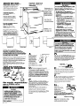
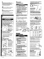
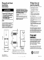
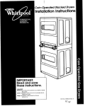
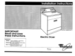
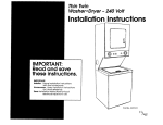
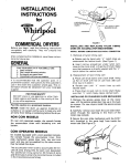
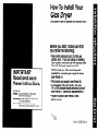
How To Install Your
Gas Dryer
(This dryer is set to operate on Natural Gas.)
Before you start, make sure that
you have the following:
l
l
IMPORTANT:
!
these instructio lns.
IMPORTANT:
Installer: Leave Installation Instructions
with the homeowner.
Homeowner: Keep Installation Instructit ons
for future reference.
Save Installation Instructions for local
electrical and gas inspector’: i use.
l
l
l
New metal exhaust duct. Do Not use
plastic duct. If you are using an existing
duct system, remove any lint buildup (see
Panel B, “Exhaust requirements”).
All the tools you will need and parts
needed to connect gas supply to dryer.
(see Panel A ).
The proper gas supply (see Panel A).
A grounded 120~volt, 60-Hz, AC-only,
15 or 20-ampere fused electrical circuit
(see Panel B, “Electrical requirements”).
Proper location (see Panel A and
back cover).
Part No. 3395332 Rev. B
Before you start...
Important:
Observe all
governing codes and
ordinances.
Check location where dryer will be
installed. Proper installation Is your
responsibility. The dryer must not
be installed or stored in an area
where it will be exposed to water
and/or weather. Make sure you
have everything
necessary for
conect installation.
Check code
requirements: Some
codes llmlt or do not
permlt installation of
clothes dryers In
garages, closets,
mobile homes, or
sleeping quarters.
Contact your local
bullding inspector.
Proper gas and electric
supply connections should
be available.
Protectlon from the weather:
Proper operation
of dryer
cycles requires temperatures
above 45°F.. or the dryer
may not shut off when
automatic
cycles are used.
‘8”
max.
Open dryer and
remove llterature
and parts packages.
Four-inch metal exhaust
duct is required.
Support: The floor must be
able to support dryer weight
of 175 pounds.
\
gas burner inlet
pipe connection
at rear d dryer
Level floor: l-inch
maximum floor slope
under entire dryer.
Dryer Door Clearances
Locatlon must be large enough to
dryer door. See back
cover of Installation Instructlons or
label on dryer rear panel for
recessed and closet requlrements.
fully open
Full-Wldth
Hamper Door
Mobile
Fire Hazard
lf you Install the dryer In a garage, car-port,
or areas near vehicles where fumes from
gasoline or other flammable materials may
be present, the vapors may be heavier than
air and remain near floor. Place dryer a
mlnlmum of 18 Inches above floor. Check
wlth your bulldlng Inspector regarding
requirements for thls Installation.
Failure to follow these lnstructlons could result
In fire or explosion.
Extra-large
Hamper Door
(shown above)
Home Installation
This appliance Is sultable for moblle home
Installations. The Installation of the dryer must
conform to the Manufactured Home Constructlon
and Safety Standard, Title 24 CFR, Part 3280 (formerly
the Federal Standard for Moblle Home Constructlon
and Safety, Title 24, HUD, Part 280).
For moblle home use, thls appliance
MUST be
fastened to the floor and MUST be exhausted
to the
outside. Order Mobile Home Installation Kit No.
346765 from your dealer. Kit includes the necessary
fastening hardware and detailed installation
instructlons. Metal exhaust system hardware
is also
available
through your dealer.
This installation must conform wlth American
National Standard, National Fuel Gas Code ANSI
2223.1 - latest edition, and all local codes and
ordinances.
Tools and materials
needed for installation:
metal exhaust duct
as supply connection
lor
A
n Check that
dryer Is equipped
with the correct
burner for the
*
*\ I
particular type of
gas in the home.
Burner information
’
will be found on
I,
the serial/rating
#c
plate In door well
of the appliance.
If
this information does not agree with the type of
gas avallable,
see your dealer.
B
n TI?is dryer is equipped
for use with
NATURAL GAS. It is designcertified
by A.G.A. for
L.P. (propane
or butane) gases with
appropriate
conversion.
No attempt shall be
made to convert the appliance
from the gas
specified on the serial/rating
plate for use with
a different gas without consulting the serving
gas supplier. Convenlon must be done by a
qualified servlce technlclan. Gas converslon
klt part numbers are llsted on the gas valve
burner base.
duct tape
Gas supply requirements
OBSERVEALL GOVERNING CODES AND
ORDINANCES.
Fire Hazard
This dryer must be connected to a
regulated gas supply. Failure to do so
could cause hlgh-pressure gas release,
resulting In a flre or exploslon.
l Have the L.P. gas checked
by a quallfled
person before lnstalllng the dryer. The L.P.
gas supply must not exceed a pressure 0r
13” water column.
l New flexible
tubing should be used.
Reusing old flexible tubing mlght result In
possible leaks or fire hazard.
Failure to follow these lnstructlons may result
In flre or explosion.
l
Panel A
Fire Hazard
For your safety the information in this
manual must be followed to minimize
the risk of fire or explosion or to
prevent property damage, personal
injury or loss of life.
- Do Not store or use gasoline or
other flammable vapors and liquids
in the vicinity of this or any other
appliance.
- WHAT TO DO IF YOU SMELL GAS
l
Do Not try to light any appliance.
l
Do Not touch any electrical
switch; Do Not use any phone in
your building.
l
Clear the room, building or area
of all occupants.
l
Immediately call your gas
supplier from a neighbor’s
phone. Follow the gas supplier’s
instructions.
l
If you cannot reach your gas
supplier, call the fire department.
- Never install dryer up against
draperies or curtains or on carpet.
- Keep any and all items from falling
or collecting behind the dryer.
Installation and service must be
performed by a qualified installer,
service agency or the gas supplier.
C
n The design of this dryer has been
certified by the American Gas Association for
use at altitudes up to 10,ooO feet above sea
level at the B.T.U. rating indicated
on the
model/serial
plate. Burner input adjustments
are not required when the dryer is operated
up
to this elevation.
When installed above 10,000 feet, a four
percent (4%) reduction of the burner B.T.U.
rating shown on the model/serial
plate is
requlred for each 1,COOfoot increase in
elevation.
For assistance when converting
to
other gas types and/or installing above 10,000
feet elevation,
contact your local service
company.
D
n Provide a rlgld gas supply line to the
dryer location. When riGd pip&-isbsed
it should
be l/2 inch IPS. When acceptable
to the gas
supplier and local codes, 3/8-inch approved
tubing may be used for lengths under 20 feet.
For lengths over 20 feet, larger tubing should be
used. Pipe-joint compounds
resistant to the
action of L.P. gas must be used.
shutoff valve
“open” position
E
n The supply line shall be equlpped
with a
shutoff valve. This valve should be located in
the same room as the dryer and should be in a
location that allows the valve to be opened
and closed easily. Do not block access to
shutoff valve.
P
n If the dryer is installed in a confined
area
such as a bedroom,
bathroom
or closet,
provision must be made for enough air for
combustion
and ventilation.
Check governing
codes and ordinances.
Also, check recessed
and closet installation instructions section or
label on dryer rear panel for detailed
instructions.
G
n If local codes
permit, it is
recommended
that new
flexible metal tublng,
deslgn-certified
by the
American Gas
Association, be used for
connecting
the
appliance
to the rigid gas
supply line. (The gas pipe which extends
through the lower rear of the appliance
j/g-Inch male pipe thread.)
H
1 If rigid pipe is used as a gas
supply line, a combination
of pipe
fittings must be used to obtaln an
in-line connection
to the dryer.
has
I
n Make sure that lower edges of the
cabinet, plus the back and bottom sides of the
dryer are free of obstructions to permit
adequate
clearance
of air openings for
combustion
air. See “Recessed and closet
Installation instructions”, on the back cover, for
minimum spacing requirements.
Electrical
requirements
Electrlcal Shock Hazard
ElectrIcal ground Is required on thls
appliance.
Do Not modlty the power supply cord plug.
H It does not flt the outlet, have a proper
outlet Installed by a quallfled electrlclan.
Do Not have a fuse In the neutral or
groundlng clrcult. A fuse In the neutral or
grounding clrcult could result In an
electrlcal shock.
Do Not use an extension cord wlth thls
appliance.
Check wlth a quallfled electrlclan lf you are
In doubt as to whether the appliance Is
properly grounded.
Failure to follow these lnstructlons could result
In serious Injury or death.
J
K
n A 1/&inch NPT plugged
tapping,
accessible
for test gauge connection,
must be
installed immediately
upstream of the gas
supply connection
to the dryer.
The dryer and its individual shutoff valve must
be disconnected
from the gas supply plping
system during any pressure testing of that
system,
H codes permit and a separate groundlng wire
Is used, It Is recommended that a quallfled
electrlclan determlne that the groundlng path ls
adequate.
ElectrIcal Shock Hazard
Disconnect from electrlcal supply before
removing access panel.
Do not operate dryer wlthout access panel
securely In place.
Failure to follow these lnstructlons could
result In electrlcal shock or death.
One-piece
front panel
irlng diagram location
The dryer gas shutoff
valve is located
behind the one-piece
front panel.
The wiring diagram is
located inside the
console.
These Items should be
accessed only by a
quallfled service
technlclan.
e-piece front panel
1. Disconnect electrlcal supply.
2. Remove lint screen and set aside.
3. Remove two screws from lint screen area.
4. Grasp front cabinet top corners and pull
forward and up (top is hinged at rear).
5. Remove two screws from front panel
flanges. Lift front panel off lower clips.
6. Remove door switch wires, if necessary,
and set front panel aside.
7. Reassemble in reverse order.
Note: The door switch wires must not touch
panel
electrlcal supply.
2. Insert flat-blade
screwdriver
between
cabinet front and
lower access panel 3
inches in from each
side. Push down on
retainer clips and
pull lower access
panel forward. The
lower access panel
is hinged at the
bottom.
3. Close lower access
panel.
Gas shutoff valve “open”
“closed”
position
gas
Panel B
and
Optional shutoff
valve L-3
I2
Ll-
Metal flexible duct should be fully extended
and supported
when the dryer is in final
position. DO NOT KINK OR CRUSH THE DUCT.
The metal tlexlble duct must be completely
open to allow adequate exhaust alr to flow.
Allow as much room as possible when using
elbows or making runs. Bend duct gradually
to
avoid kinking. Remove excess flexible duct to
avold sagging and kinking that may result in
reduced air flow.
The exhaust outlet
Recommended
grounding method
The exhaust duct can be routed up, down, left,
For your personal safety, this appliance
must be
grounded.
This appliance
is equipped
with a
power supply cord havlng a 3-prong grounding
plug. To minimize possible shock hazard, the
cord must be plugged Into a mating 3-prong
grounding-type
wall receptacle,
grounded
in
accordance
with the National Electrical Code,
ANSVNFPA 70 - latest edition, and all local
codes and ordinances.
If a mating wall
receptacle
is not available,
it is the personal
responsibility and obligation
of the customer to
have a
3-prong rounding- properly
type wal $receptacle
mm Indad
power supply cord
Exhaust
requirements
Fire/Health Hazard
use non-metal, flexible duct.
use metal duct smaller than four
In diameter.
Use exhaust hoods wlth magnetic
Do Not
Do Not
Inches
Do Not
latches.
Check that exhaust system Is not longer
than specltled. Exhaust systems longer
than speclrled will:
- Accumulate Ilnt.
- Shorten the llte ot the dryer.
- Reduce performance, resulting In
longer drying times and Increased
energy usage.
Failure to r0ll0w speclflcatlons may result In a
Hre.
l
is located at the
bottom rear of
the dryer.
right or straight out of the back of the dryer.
General space requirements
can be found in
“Recessed and closet installation instructions’
on the back cover. Use the straightest path you
can, where possible, to avoid 90” turns.
The maxlmum length of the exhaust
system
depends upon the type of duct used, number
of elbows and type of exhaust hood. The
maximum length for both rigid and flexible duct
is shown in chart.
YUMBER OF
30” TURNS
qualified
electrician.
l
wiring diagram location
1 aDlsconnect
installation to use the
fewest number of
elbows and turns.
A 120-volt, 60Hz. AC-only, 15or 2sampere
fused electrical supply Is required.
Time-delay
fuse or circuit breaker is recommended.
It is
recommended
that a separate circuit serving
only thls appliance
be provlded.
l
access
Four-Inch rlgld metal
DIW Is Dreferred. Plan
l
l
II
n
l
l
poritic
Use duct tape to seal
all joints.
l
w For ease of installation, operating
and
servicing (if ever needed) adequate
space
should be provided around the dryer.
lower
If uslng exlstlng exhaust system, clean llnt from
entire length of exhaust system. Make sure
exhaust hood Is not plugged with Ilnt.
Replace plastic exhaust duct wlth rlgld metal or
flexible metal duct.
l
Do Not exhaust dryer Into a chimney,
furnace cold alr duct, attlc or crawl space,
or any other duct used for ventlng.
* Clean the exhaust system every other year.
Do Not Install flexible duct In enclosed
walls, celllngs or r loors.
9ccumulated llnt could be fuel for a flre or
:ause molsture damage.
l
l
Ixhaust the dryer outslde to prevent
exposure to substances In the gas fuels and
:ombustlon which may be harmful to your
.lealttl .
The molsture and llnt Indoors may cause:
- Llnt to gather lnslde and around the
dryer and be a fuel for flre.
- Molsture damage to woodwork,
turnlture, palnt, wallpaper, carpet, etc.
- Housecleanlng problems and possible
health problems.
Failure to follow these lnstructlons could result
In flre damage, property damage, personal
injury or health problems.
EXHAUST
AI
HOOD WPE
6
IC
64Fr.
54Fr.
44Fr.
04Fr.
54Fr.
44FT.
46 F
35 Fr.
35 FT.
29 F
27 FT.
27 FT.
21 F
30Fr.
30 Fr.
20 FT.
31 Fr.
31 Fr.
23 FT.
27 FT.
27 FT.
19FT.
25 FT.
25 FT.
17FT.
23 FT.
23Fr.
15Fr.
58 F
MAXIMUM
LENGTH OF
4’ DIA. RIGID
METAL
DUCT.
30 F
I
MAXIMUM
LENGTH OF
4’ DIA.
FLEXIBLE
METAL
DUCT.
The maximum length using a 2” x 6” rectan ular duct
wlth 2 elbows and a 2-l/2 (IYPE C) exhaus 9 hood is 8 ft.
For exhaust systems not covered by the
exhaust length chart, see Service Manual,
No. 603197 available
from your local parts
distributor.
Part
Service check: The back pressure in any
exhaust system used must not exceed 0.6
inches of water column measured with an
lncllned manometer
at the point that the
exhaust duct connects the dryer.
An exhaust hood should cap
the exhaust duct to prevent
exhausted
air from returning
into dryer. The outlet of the
hood must be at least 12
inches from the ground or
anything else that may be in
the path of the exhaust.
35
12” min.
d-Inch outlet hood Is preferred. However,
a
2-l /2 inch outlet may be used wlth short
systems only. A 2-l /2 inch outlet can result in
longer drying times than other hood types. For
permanent Installation, a stationary exhaust
system Is required.
For moblle home
Installation, the dryer must
have an outside exhaust.
If you exhaust the dryer
through the floor and the
area under your mobile
home is enclosed, the
exhaust system must
terminate outside the
enclosed area. Extension
beyond the enclosure will prevent lint and
moisture buildup under the mobile home.
Now start...
With dryer in laundry
1
n
corners,
area.
18.
If your dryer has tape
remove tape.
at front
2
n Open dryer
and remove the
llterature and parts
packages.
If your
dryer has tape on the
door, remove tape,
open door and remov
the tape from dryer drum. Remove drying rack
if your dryer has one. Remove all parts from the
plastic packages.
Make sure you have four
leveling legs.
Numbers
correspond
to steps.
I
--a
6.
6.
/
6.
a
n If your dryer drum was taped, move
drum counterclockwise to make sure all
tape was removed. Wipe the interior of
the drum thoroughly with a damp cloth to
remove any dust before using the dryer.
8
n Move the dryer close to its final location,
but leave enough room to connect exhaust
duct and gas supply. Remove cardboard
or
hardboard.
To make sure the dryer is level, take
a carpenter’s
level and place it on the top of
the dryer, first side to side, then front to back. If
the dryer is not level, adjust the legs of the dryer
up or down, The dryer must be level to prevent
noise and to provide good drying
performance.
-
13
n Connect
exhaust duct to exhaust
hood and dryer. (See Exhaust requirements,
Panel 6.)
l
Use the straightest path possible to avoid
90” turns.
l
l
4
Use duct tape to seal all joints in the exhaust
system.
Use caulking compound
to seal exterior wall
openlng around exhaust hood.
n
Take two of the corner pieces from the
carton and place them on the floor In back of
the dryer.
5
n Firmly grasp the body of the dryer and
gently lay it on its back on the cardboard
corners.
6
w With one of me
legs in hand, check the
ridges for a diamond
marking. That’s how far
me leg is supposed to go
into the hole. Start to
screw the legs into me
holes by hand.
w Check
that all legs are
properly Installed and
that dryer is level.
9
r
n Remove the red CaD from the aas DIDe.
Move the dryer Into its finai posttlon.
’ ’
15
10
w Connect aas SUDDIV to drver. Use
pipe-joint compound-resistant
‘to the action of
L.P. gas for gas connections.
If flexible metal
tubing Is used, be certain there are no kinks.
n Check to make sure you have all
the tools you started with (see Panel A).
16
n Plug the
power supply cord
into the grounded
outlet.
17
location.
installed
Carefully slide dryer into its final
Check to be sure legs were properly
and dryer is level.
n
rigid gas supply line
11
H Turn me shutoff valve in the gas
supply line to the “open’ position.
Use a wrench or 1” socket wrench to finlsh
turning the legs until you reach the diamond
mark.
Floor Damage
Slide dryer onto cardboard or hardboard
before movlng across rloor.
Failure to do so may cause damage to rloor
coverlng.
7
n Now stand the dryer up. Slide dryer onto
cardboard
or hardboard.
Panel C
Fire Hazard
Do Not use an open flame to test ror leaks
tram gas connections.
Check@ tar leaks wlth a flame may result In
a fire or exploslon.
12
H Use a brush and liquid detergent
to
test all external gas connections
for leaks.
Bubbles around connections
will indicate a
leak. If a leak appears, shut off gas valve
controls and tighten connections.
Then check
connections
again.
18
m Read me Use
and Care Guide to fully
understand
your new
dryer. Use a full heat cycle
(not me air cycle) for at
least five minutes to
remove air from me gas
timer control knob
supply Ilne. Open the dryer
door. You should feel heat inside the dryer. If
you do not feel heat, shut off the dryer for five
minutes. Check that the gas supply line shutoff
valve is in ‘open’
position. Repeat the fiveminute test.
To get the most efficient use from
your new dryer, read your Use
and Care Guide. Keep
Installation Instructions and
Guide close to dryer for
easy reference.
If dryer does not
operate properly...
Recessed and closet
installation
fnstrrrctions
To PREVENTLARGE AMOUNTS OF LINTAND
MOISTUREFROM ACCUMULATING, TO MAINTAIN
DRYING EFFICIENCY AND TO PREVENTEXPOSURE
TO POSSIBLEHEALTHHAZARDS, THIS MACHINE
MUST BE EXHAUSTEDOUTDOORS.
Fire/Health Hazard
Exhaust the dryer to the outslde to prevent
exposure to substances In the gas tuels
and combustion by-products which may
be harmful to your health.
It dryer Is Installed In a closet, the dryer
MUST be exhausted outslde.
Failure to do so may result In a flre or health
l
Companion
appliance
spacings should be
considered.
Detailed space requirements
can be found on
the label located on the back panel of dryer.
l
NOTE: No other tuel-burnlng appliance
Installed In the same closet.
Before calling for service, check to be sure that:
A. Electrical supply is connected.
B. The house fuse has not blown or
circuit breaker has not trlpped.
C. Door is closed.
D. Controls are set in a running or “ON”
position.
E. Start button has been pushed firmly.
F. Gas supply line shutoff valve is open.
When movlng the dryer...
l
may be
l
l
The following installation spacings and door air
openings for the dryer are possible when
installed and exhausted
as noted. (Spacing as
indicated
is in Inches and is minimum
allowable.
For ease of installation and service,
additional
spacing should be considered.)
,c
l
l
Before installing your dryer in your new home,
check wlth your gas supplier or dealer to see
that your dryer is equipped
with the correct
burner for the particular type of gas in your new
home. Burner Information may be found on
the rating plate in the door well of the dryer.
.
b
If you need
assistance...
0
Check your Use and Care Guide for a toll-free
number to call or call the dealer from whom
you purchased
this appliance.
The dealer is
listed in the Yellow Pages of your phone
directory under ‘Appliances
- Household Major - Service and Repalr.”
When you call, you will need the dryer model
number and serial number. Both numbers are
on the serial/rating
plate located in the door
well behind dryer door and on front of opening.
I
Closet door
+I?“*
Recessed front view
Part No. 3395332 Rev. B
01994 Whirlpool Corporation
Disconnect
the power supply cord and tape
securely to dryer.
Shut off the gas supply valve controls in the
gas supply line.
Disconnect
gas pipe fittings from dryer and
cap the gas supply line.
Tape the drum to the front panel. Tape the
dryer door, lint screen lid and end of dryer
gas pipe.
Turn leveling legs all the way in.
Closet installation side view
7 Additional clearances
for Wall. door and floor moldings
may be required,
** Opening is minimum for closet door. Louvered door with
equivalent
air openings is acceptable,
*** Additional
space is needed when external exhaust elbow
Benton
Harbor,
Michigan
is used
49022
Printed on recycled
paper.
10% post consumer waste/
50% recovered
materials.
Printed in U.S.A.