1
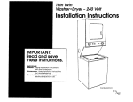
Thin Twin
WasheriDryer 230 Volt, 50 Hz
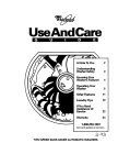
In Skrllation
IMPORTANT:
Read
and save
these instructions,
I
IMPORTANt
Insbller:
Leave Installation Instruct’- Ions
with the homeowner,
Homeowner: Keep Installation lnstr
uctions
future reference,
Save Installation Instructions for locc
electrical inspector’s use. 31
for
sfrucfions
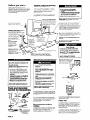
Before you start...
Check locatlon where washer/dryer
will be
installed. Proper installation is your
responsibility. The washer/dryer
must not be
installed or stored in an area where it will be
exposed to water and/or weather. Make
sure vou have evervthina
necessarv for
correct installation. _
-
Important: Observe all governing
codes and ordinances.
Electric Shock Hazard
Check code requlrements. Some codes limit
or do not permit the installation of clothes
dryers in garages, closets, mobile homes and
sleeping quarters. Contact your local
building inspector.
It Is the customer’s responslblllty:
To contact a quallfled electrlcal
Installer.
To assure that the electrlcal lnstallatlon
Is adequate and In conformance wlth
all local codes and ordinances.
l
l
Check utllltles: Proper electrical
be available.
Panel A.
Earthed electrlcal
See *Electrical
supply must
requirements,”
Failure to follow these lnstructlons could
result In death or serlous InJury.
outlet is
required. See “Electrical
requirements,”
Panel A.
Hot and cold water faucets
Water heater: Set to deliver
must be within 4 feet
(122 cm) of the back of the
washer/dryer
and provide
water pressure of 5-100 psi
(34.56T.6
kPa).
water
Laundry tub draln system needs a 20-gallon
MI I
/
Standplpe draln system needs a
two-inch (5 cm) diameter
standpipe
with a minimum carryaway capacity
of
T
The hot and cold
water inlets on back
of washer have
3/4-l l-1/2 Americ
standard threads.
Floor draln system
/
requires a siphon break,
Part No. 285320,
available
from your
authorized
parts
distributor.
large enough to fully
open dryer door 90”.
See “Recessed and
closet installation
instructions” and “Pro
dimensions,”
Panel E.
vel tloor: Maximum
slope under washer/dryer,
and clothes
ust be sturdy enough to
dryer weight with water
of 375 pounds (170 kilograms).
Electrical requirements
l
Failure to tallow these lnstructlons may
result In personal InJury.
l
l
Fire Hazard
Do Not use or store gasoline, palnt,
thinners and other flammable materials
near washer/dryer. Fumes from such
materials could result In flre or
exploslon.
Never Install washer/dryer up agalnst
draperies or curtains or on carpet. To
do so may result In a flre.
Keep any and all Items tram falling or
collecting behlnd the washer/dryer.
Failure to do so may result In a flre.
Replace all access panels betore
operating washer/dryer.
Failure to follow these lnstructlons may
result In a flre, exploslon or electrlcal
shock.
Tools and materials
needed for fnstaIIation:
l
l
l
l
l
l
Electrlcal Shock Hazard
Electrlcal earth Is required on thls
appliance.
Do Not earth to a gas pipe.
Do Not modify the power supply cord
plug. It It will not Ilt the outlet, have a
proper outlet Installed by a qualltled
electrlclan.
Do Not reuse an old power supply cord.
Possible electrlcal shock or tire hazard
could occur It old power supply cord Is
used.
Do Not have a ruse In the neutral or
earthlng clrcult. A ruse In the neutral or
earthlng clrcult could result In an
electrlcal shock.
Do Not use an extension cord wlth thls
appliance.
Check wlth a quallfled electrlclan as to
whether the appliance Is properly
earthed.
Failure to follow these lnstructlons could
result In death or serious InJury.
A two-wire, plus earthing wire, single-phase,
230-volt, %-Hz, AC-only, 15-ampere electrical
supply is required on a separate circuit. A
time-delay
fuse or circuit breaker is
recommended.
Recommended
method
Panel A
SEERECESSEDAND CLOSET INSTALLATION
INSTRUCTIONSON PANEL E.
slio-ioint oliers
thbtbpeli
to
1 - l/2” mlnimum
Do Not store or operate washer/dryer
below 32°F (0%) (some water may
remain In washer). Proper operatlon of
dryer cycles requires temperatures
above 45°F (7°C). See Use & Care Guide
tar “Wlnterlzlng” Intormatlon.
Failure to follow these lnstructlons may
result In damage from freezlng.
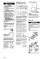
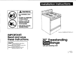
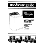
Power supply cord
Two-wire
power
supply cord
Figure 1
0
Iail
000
It codes permit and a separate earthlng wire
Is used, It Is recommended that a quallfled
electrlclan determlne that the earthlng path
Is adequate.
l/4” rocket wrench
or nut driver
Four-Inch (10.2-cm) metal exhaust duct Is
This appliance
is equipped
with a 15-amp-rated
Schukotype power supply co
Personal InJury Hazard
More than one person Is required to Ilft,
tilt, or move thls washer/dryer because of
Its weight and size.
l
I
Product Damage
Locatlon should be
l
(76 liters) laundry tub. Top of laundry tub
must be at least 28 inches (71 cm) high and
no higher than 48 inches (122 cm) from floor.
If a longer drain hose is needed, drain hose.
Part No. 388423, and hose connection
kit,
Part No. 285442, are available
from your
authorized
parts distributor.
Dryer may be exhausted
from rear or left or
right side. Exhausting through the side
requires side exhaust kit Part No. 279823. See
“Exhaust requirements,”
Panel B.
must be at lea
and no higher than
48 inches (122 cm) from
floor.
140°F (60°C)
to the washer.
earthing
For your personal safety, this appliance
must
be earthed. This appliance
is equipped
with
a Schuko-type
power supply cord. To
minimize possible shock hazard, the cord
must be plugged into a mating wall
receptacle.
See Figures 1 and 2.
0
two-wire
receptacle
Figure 2
If your electrical
requirements
are different,
contact your authorized
service center or a
qualified electrician.
Direct wire
The dryer can be connected
directly to the
fused, disconnect
or circuit breaker box with
two-wire or three-wire flexible, armored or
non-metallic
sheathed copper cable (with
earthing wire). Do Not use two-wire with
bare earthing wire. All current carrying wires
must be insulated.
A conduit connector
must be installed at the
junction box. USE ONLY lo-GAUGE SOLID
COPPER WIRE. DO NOT USE ALUMINUM WIRE.
Allow four feet of slack in the line so the
dryer can be moved if servicing is ever
necessary.
Exhaust reauirements
Fire Hazard
. Do Not use non-metal, tlexlble duct.
Do Not use metal duct smaller than
4 Inches (10.2 cm) In diameter.
. Do Not use exhaust hoods wlth
magnetic latches.
Check that exhaust system Is not longer
than specltled. Exhaust systems longer
than specltled will:
- Accumulate Ilnt.
- Shorten the llte ot the product.
- Reduce performance and result In
longer drylng times and Increased
energy usage.
Failure to r0ii0w speclrlcatlons may result In
a tlre.
Do Not exhaust the dryer Into a
chimney, turnace cold alr duct, attlc or
crawl space, or any other duct used tar
ventlng.
Clean the exhaust system every year.
Accumulated llnt could be tuel tar a tlre or
cause molsture damage.
Exhaustlng your dryer Indoors Is Not
recommended. The molsture and llnt
Indoors may cause:
- Lint to gather lnslde and around the
dryer and be a fuel tar tlre.
- Moisture damage to woodwork,
furniture, palnt, wallpaper, carpet, etc.
- Housecleanlng problems and possible
health problems.
Failure to tallow these lnstructlons could
result In tire damage, personal InJury or
health problems.
Mobile home installation
Maxlmum length of the exhaust system
depends upon the type of duct used,
number of elbows and the type of exhaust
hood. The maximum length for both rigid
and flexible duct is shown in the chart.
l
(10.2 cm)
0
~~ft(i3.1m) 41ft(l2.5m)
36ft(ii.Om)
1
33ft(iOm)
31ft (9.4m)
26ft(7.9m)
2
23ft (7.0m)
21ft (6.4m)
16ft(4.9m)
3
Wft(55m)
lSft(5.5 m)
0
3Oft(9.1m)
29ft(8.8m)
24ft(73m)
1
24ft (7.3m)
23ft(7.0m)
18ft(5.5m)
2
lSft(4.9 m)
15ft(4.6m)
lOft(3.0m)
3
iOft(3,Om)
gft(2.1 m)
l
l
l
d4”
2-W
(6.4cm)
(dcm)
d!arneter
outslde
wall
ridd
meti
duct
Not
recommended
rldor
flexible
metal
*’
Thls appliance
Installations.
Moblle home exhaust requlrements: The
washer/dryer
must have an outside exhaust.
If the dryer is exhausted
through the floor
and the area under the mobile home is
enclosed, the exhaust system must terminate
outside the enclosed area. Extension
beyond the enclosure will prevent lint and
moisture buildup under the mobile home.
Not
recommended
l
If uslng an exlstlng exhaust system, clean llnt
tram entlre length of exhaust system. Make
sure exhaust hood Is not plugged wlth Ilnt.
The exhaust system should be Inspected and
cleaned yearly.
Replace any vlnyl or metalllzed plastic toll
exhaust duct wlth rlgld metal or tlexlble
metal duct.
Use duct tape to seal all
joints. Do Not use screws
to secure duct.
air flow
good
Four-Inch (10.2 cm) rlgld
metal pipe is preferred.
Plan installation to use
the fewest number of
elbows and turns.
I-I
Metal tlexlble duct must be fully extended
and supported
when the dryer is in its final
position. DO NOT KINK OR CRUSH THE DUCT.
The metal tlexlble duct must be tully
extended to allow adequate exhaust alr to
ri0w.
Allow as much room as possible when using
elbows or making turns. Bend duct gradually
to avoid kinking. Remove excess flexible
duct to avoid sagging and kinking that may
result in reduced air flow.
The exhaust duct can
be routed up, down,
left, right or straight out
the back of the
washer/dryer.
Space
requirements
are
provided on Panel E
and on the rear panel
of the washer/dryer.
Use
the straightest path
possible to avoid 90
turns.
For exhaust configurations
other than those
listed in chart the back pressure MUST not
exceed 0.2 inches water column at the back
of the washer/dryer.
The back pressure should
be checked
by a qualified technician.
Now start...
With washer/dryer
For exhaust systems not covered
by the
with your dealer
Service check: The back pressure in any
exhaust system used must not exceed
0.2 inches of water column measured with an
inclined manometer
at the point that the
exhaust duct connects to the dryer.
Exhaustlng the dryer ouklde is recommended.
Recessed installation that is not exhausted
outside must use Exhaust Deflector Kit Part
No. 694609, available
from your authorized
parts distributor. See “Recessed and closet
installation instructions,” Panel E, for
unobstructed
air opening requirements.
Failure to follow thls InstructIon may result
In personal Injury.
Truck only tram the rear to prevent produce
damage.
1
n Put on safety glasses and gloves.
provision must be made for enough air for
ventilation.
Check governing
codes and
ordinances.
Also refer to the “Recessed and
closet installation instructions” on Panel E.
An exhaust hood should cap the exhaust duct
to prevent exhausted
air
from returning into dryer.
The outlet of the hood
must be at least
12 inches (30.5 cm) from
the ground or any object
12” (30.5 cm)
that may be in the path
minimum
of the exhaust.
!l!!!r
Four-Inch (10.2~cm) outlet hood Is preferred.
However, a 2-l/2 inch (6.4 cm) outlet hood
may be used with short systems only.
A 2- l/2 inch (6.4 cm) outlet hood can result in
longer drying times than other hood types. For
A
permanent Installation, a statlonary exhaust
system Is required.
W Remove
cardboard
shipping
base.
Exhaustlng the dryer through the slde of the
washer/dryer
requires the use of Side Exhaust
Kit, Part No. 279823,
available
from your
authorized
parts distributor.
Follow kit Installation
Instructions for proper
exhaust installation.
l
l
l
l
4 legs
I drain hose clamp
1 plastic beaded
strap
4 large, waterhose washers
3
Check
Panel B
in laundry area.
Personal Injury Hazard
More than one person Is required to Iltt, tilt
or move the washer/dryer because ot Its
welght and size.
It the washer/dryer Is Installed In a confined
area such as a bedroom, bathroom or closet,
It must be exhausted to the outslde and
exhaust
better
The maximum length using a 2” x 6” rectangular
duct with 2 elbows and a 2-l/2” (TYPE C) exhaust
hood is 8 ft (2.4 m).
exhaust length chart, check
or distributor for information.
Is sultable tar moblle home
2 small water-hose
washers
l
1 small clamp
l 2 faucet
adapters
* drain hose adapter
and clamp
(not shown)
l
W Remove parts from plastic package.
that all parts were included.
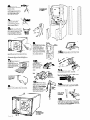
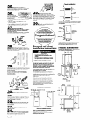
4
1 Insert a rearleveling leg into the hole in
the rear corner on the
bottom of the
washer/dryer.
Push leg in
until it snaps into place. Do
the same same thing with
the other leveling leg in
the other rear corner.
5
check
other
Check
same
adjust,
-w/
A
Numbers
correspond
to steps.
h
n Push up one leg:
to see that the
leg goes down.
the other leg the
way. (If legs do not
repeat Step 4.)
6
n With one of the front
legs in hand, check the ridges
for a diamond marking. That’s
how far the leg is supposed
to go into the hole. Start to
screw the legs into the holes
in the front corners by hand.
Do Not
Remove
9
Use slip-joint pliers to finish turning
legs until you reach the diamond
the front
mark.
rear
H Remove the two
rear corner posts located
at the back of the
washer/dryer.
Remove
the two corner pieces
attached
to the lower
front of the washer/dryer.
Do Not remove the foam
shipping pieces between
the washer and dryer until
me washer/dryer
is in
place,
corner
posts
12
n Remove yellow card. Take hoses
out of basket. Place hoses with other parts.
Slide washer/dryer onto cardboard or
hardboard before movlng across floor to
prevent damage to floor coverlng.
10
n Place a piece of
cardboard
or
hardboard
in front of
carton. Now stand the
washer/dryer
upright.
Slide washer/dryer
onto
cardboard
or
hardboard.
H Move
foam shipping
pieces outward just
enough to clear the
washer lid. Open
me washer lid. The
latch under the
dryer will hold lid
open.
H Release washer
lid by pushing up on latch.
Use new hoses and washers that came
with your washer/dryer.
I
To prevent
product
out of washer.
damage, Do Not
remove corner
posts inside the
carton before
cutting.
8
\\ 3 shipping
11
.
n With me corner posts in
place, cut the carton
Remove carton.
Close lid.
down
one corner.
8.
straps
coupling
washer
n Read the yellow
card. Place hand on top of
agitator when removing the
shipping straps. Firmly jerk,
then pull the three shlpplng
L
straps up until each strap
with key is completely
removed from washer, Put v
straps in the same area as
other shipping pieces.
/
%
A
14
three
shipping
straps
with keys
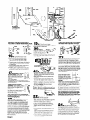
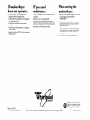
n Insert a large washer into each
end of the inlet hoses. Check that washers
are firmly seated in couplings.
Inlet valves are
plastic. Do Not
overt1 hten or
crosst it read.
n Attach inlet hose to bottom
inlet valve opening first. Attach second inlet
hose to top inlet valve. Tighten couplings by
hand; then use pliers to make an additional
two-thirds turn. Do Not overtlghten; this could
cause damage
to coupling.
Numbers
corresponc
to steps.
Panel
18.
24.
24.
Numbers
correspond
to steps.
19
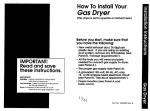
IMPORTANT: THIS PROCEDUREMUST BE
FOLLOWEDTO ASSUREPkOPER INSTALLATION.
n Put “hook” end of drain
hose into laundry tub or standpipe.
Check
proper length of drain hose.
clamp
for
CHECK THAT DRAIN HOSE IS NOT TWISTED
OR KINKED AND IS SECURELYIN PLACE.
A
B
20
Pk!
(drain
connector
n Betore
attaching
water inlet
hoses, run water through
both faucets into a
bucket. This will get rid of
any particles in water lines
that might clog hoses. Mark which is the hot
water faucet.
l/4”
(.64 cm)
dra\in
hose
WICIX.
16
n To prevent the drain hose
from coming off or leaking, it must be
installed per the following instructions:
1. Wet the inside end of the drain hose with
tap water. DO NOT USEANY OTHER
couPling
larger
washer
faucet
adapter
smaller
washer
LUBRICANT.
2. Squeeze ears of small clamp with pliers to
open clamp and place clamp over end
of drain hose.
3. While holding clamp open, work end of
drain hose onto drain connector.
4. Position clamp over the drain hose area
marked “clamp.”
Release clamp. Clamp
should be1 /4 inch (64 cm) from end of
drain hose.
17
W Standplpe or laundry
tub draln system: Open hose
clamp and slide over “hook”
end of drain hose to secure the
rigid and corrugated
sections
together.
Floor drain system:
l
I -;~
R
l
l
Do Not install “hook” end of drain hose to
corrugated
section. Consult your plumber for
proper installation,
l
It drain hose does not tit into
standplpe, install adapter. Open
other hose clamp with pliers and
place clamp over rigid end of
drain hose.
l
For both Inlet hoses: Insert larger washer
into end of coupling; then attach faucet
adapter.
Insert smaller washer into end of
faucet adapter.
Make sure washers are firmly seated into
couplings.
Attach bottom hose with adapter (inlet
marked ‘H”) to hot water faucet. Attach
top hose with adapter (inlet marked ‘C”)
to cold water faucet.
Tighten couplings to faucets by hand; then
use pliers to make final two-thirds turn.
Do Not overtlghten; this could cause
damage
to coupler.
Move washer/dryer to its permanent
position. Remove cardboard/hardboard
from under washer/dryer.
Insert tapered end of adapter
into rigid end of drain hose up to
stops on the sides of adapter.
Secure with clamp.
Slide washer/dryer onto cardboard or
hardboard before moving across floor to
avoid damaging floor.
18
H It you have room to work Worn
either side ot ihe washer/dryer, move
washer/dryer
close to final position so you
can easily complete
the installation steps.
II you are worklng In a closet or recessed
area, move the washer/dryer
into final
position and remove cardboard/hardboard
from under washer/dryer.
Remove the two
foam shipping pieces between the washer
and dryer and place with the other shipping
pieces. Remove the two Phillips-head screws
located at the top of the access panel. (See
illustration for Step 24). Remove access
panel and set access panel and screws
aside. Complete
the following steps through
the access area.
Panel D
22
strap
strap
strap
23
n Make sure the “hook” end of
drain hose is in laundry tub or standpipe. Wrap
the plastic beaded strap around the drain
hose and laundry tub or standpipe. Thread
beaded end of strap through keyhole end. Pull
until strap is tight. Slide strap into narrow end of
keyhole to lock strap in place. See Figures A-B.
If the water inlet faucets and drain standpipe
are recessed, tightly wrap the plastic beaded
strap around the drain hose and faucet body.
(Do Not wrap strap around the faucet handles
or stems.) Thread beaded end of strap through
keyhole end. Pull until strap is tight, Slide strap
into narrow end of keyhole to lock strap in
place. See Figure C.
Secure the draln hose to
the laundry tub or
standplpe wlth the plastic
beaded strap. Failure to
properly secure draln hose
could result In water
damage.
If draln hose cannot be strapped Into place,
hose must be cut exactly to length so “hook”
end ls held iightty over edge ot laundry tub or
standplpe. See Figure D.
If a longer drain hose is needed, drain hose, Part
No. 388423 and Hose Connection
Kit, Part No.
285442 are available from your authorized parts
distributor. If drain hose must be shortened, use
Hose Connection
Kit, Part No. 285442.
Note: It washer/dryer ls moved to adjust draln
hose, the washer/dryer must be leveled agaln.
Repeat Step 22. Place cardboard under the
washer/dryer and carefully move washer/dryer
to avold damaglng rloor coverlng.
n Carefully move the
washer/dryer
into fin’al position.
l
Tilt the washer/dryer
forward, raising back
legs 1 inch (2.5 cm) off the floor so that the
rear self-leveling
legs will adjust. Gently
lower the washer/dryer
to the floor.
l
-
-
Check that the washer/dryer
is level by
placing a carpenter’s
level on top of the
washer, first side to side, then front to
back.
If it is not level, adjust the front legs up or
down.
Tilt the washer/dryer
forward, raising back
legs 1 inch (2.5 cm) off the floor so that
the rear self-leveling legs will adjust.
Gently lower the washer/dryer
to the
floor.
Check that the washer/dryer
is level.
Repeat as needed.
24
n If vou did not remove the
access panel in Step 18, remove the two
foam shipping pieces between
washer and
dryer and place with other shipping pieces,
If exhaust duct cannot be connected
from
the side of the washer/dryer,
exhaust duct
can be reached from the front through the
access panel. Remove the two Phillips-head
screws located at the top of access panel.
Set access panel and screws aside.
Closet installation
25
n Determine the length of
exhaust duct that is needed to-connect
dryer to the exhaust hood. See “Exhaust
requirements,”
Panel B.
the
-
26.
Connz
Ghaust
duct to washer/dryer
and then to the
exhaust hood.
l
Use the straightest
90” turns.
l
l
closet
door
n Remove
’
path possible
to avoid
Use duct tape to seal all joints in the
exhaust system.
Use caulking
wall opening
compound
to seal exterior
around exhaust hood.
tape from dryer
door and open dryer door. Remove tape
across the dryer lint screen. Check to be sure
lint screen is in its proper position. Wipe out
drum with a damp cloth to remove any dust.
Start drver and allow it to complete
a heat
cycle t6 make sure the dryer is working
properly.
36
n Finally, save all literature
keep with washer)dryer.
24 sq. In. (155 sq. cm)
-IT
I’
T
front view
Unobstructed
air openings are minimum for closet
door. Louvered door with equivalent
air openings
is acceptable.
*(r’ (0 cm)
and
1
27
48 sq. In.
(310 sq. cm)
n CHECK ELECTRICAL
REQUIREMENTS.BE SUREYOU HAVE CORRECT
ELECTRICALSUPPLYAND RECOMMENDED
EARTHING METHOD.
T
To get the most efflclent use from
your new Whlrlpool washer/dryer,
Check the Installation Instructions to see that
you have completed
each step. Complete
any missed steps before you continue.
( Congratulations!
Additional
space may
be needed
for exhaust
elbow.
closet
door
1
-
24 sq. In.
(155 sq. cm)
Keep lnstallatlon lnstructlons nearby
f
4
I_
1" (2.5 I ‘I)
side view
~~~~
Closet
installation
must be exhausted
outdoors.
Recessed, non-exhausted
installation
must use
only the rear exhaust position and Exhaust
Deflector Kit No. 4500 is required.
2U.
~ Check that all parts are now
Irlstalled. See parts list, Panel 8. If there is an
extra part, go back through the steps to see
which step was skipped.
~-
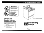
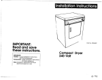
Recessed and closet
installation instructions
Product dimensions
(Shown with legs extended 1 Inch (2.5 cm)
tram bottom of washer/dryer.)
r
l
l
Fire Hazard
It Is recommended that the
washer/dryer be exhausted to the
outslde.
It washer/dryer Is Installed In a closet,
the dryer MUST be exhausted outslde.
lY'(30.5
lT(30.5
cm
Failure to do so may result In a tire.
w-w-
29
H Check that you removed all the
shipping pieces, including the three shipping
straps with keys. Dispose of all materials in
proper manner.
It you do not remove all three shlpplng
straps, your washer/dryer may “walk” away
from Its locatlon.
TO PREVENTLARGE AMOUNTS OF LINT AND
MOISTUREFROM ACCUMULATING IN THE
RECESSEDAREA, TO MAINTAIN DRYING
EFFICIENCY, AND TO PREVENTEXPOSURETO
POSSIBLEHEALTHHAZARDS, THIS APPLIANCE
SHOULD BE EXHAUSTEDOUTDOORS.
This washer/dryer may be installed in a
recessed area or closet.
The installation spacing is in inches and
centimeters
and is the minimum allowable.
Additional
spacing should be considered
for
ease of installation, servicing and
compliance
with local codes and
ordinances.
If closet door is installed, the minimum
unobstructed
air openings in top and
bottom are reauired. Louvered doors with
equivalent
air dpenings are acceptable.
Closet installation must be exhausted.
Other installations must use the minimum
dimensions indicated.
(36.2 cm)
recess width
rear view
Recessed installation
*
I
4-R
I O;(O cm)
I
12"
(30.5 cm)
31
(r’ (0 cm)
3” (7.6 cm) j
n
I I dryer I I
WTum on water faucets and
check for leaks. Tighten couplings if there is
leaking. DO NOT OVERTIGHTEN.This could
cause damage
to faucets.
washer
sure to tighten
access panel.
33
34
earthed
icrews
at each
of the
I
I
front view
H Plug power
outlet.
side view
supply cord into
n Read the Use and Care Guide
to fully understand
your new washer/dryer.
Now start the washer and allow it to
complete
the regular cycle.
Panel E
I
Mlnlmum lnstallatlon spacing
Note: If recessed installation
is exhausted,
spacing can be 0 inches (0 cm).
all
Additional
clearance
for wall, door and floor
molding may be required.
27-l/('
(69.2 cm)
side view
cm)
If washer/drver
does not opkate...
l
l
l
l
l
Check that the circuit breaker is not
tripped or the house fuse blown.
Check that power supply cord is plugged
into wall receptacle.
Check that washer lid or dryer door is
closed.
Check that controls are set in a running or
‘ON” position.
Check that dryer ‘START” button has been
firmly pushed.
If you need
assistance...
Call your dealer or local authorized
service
company.
When you call, you will need the
washer/dryer
model number and serial
number. Both numbers can be found on the
model/serial
rating plate located behind the
dryer door on the dryer door well.
When moving the
washer/dryer.. .
l
l
l
l
Part No. 3397516
01995 Whirlpool Corporation
Disconnect
the power supply cord. Tape
power supply cord securely to
washer/dryer.
Tape the dryer drum to the front panel.
Tape the lint screen in place. Tape the
dryer door closed.
Wedge a blanket between
the tub ring
and cabinet top to restrict washer tub
movement.
Turn front leveling
legs all the way in.
Printed on recycled
paper.
10% post consumer waste/
50% recovered
materials.
Prepared by Whirlpool Corporation,
Benton Harbor, Michigan
49022
Printed in USA,