1
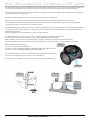
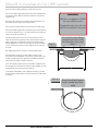
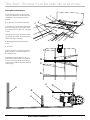
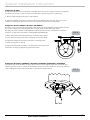
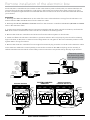
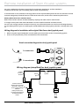
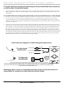
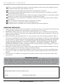
SIDE-POWER Stern Thruster Installation Manual Rev 1.7.2 Thruster Systems Installation manual is rd th a p bo ee n K al o u an m ! SLEIPNER MOTOR AS P.O. Box 519 N-1612 Fredrikstad Norway Tel: +47 69 30 00 60 Fax: +47 69 30 00 70 w w w. s i d e - p o w e r. c o m s i d e p o w e r @ s l e i p n e r. n o Made in Norway EN © Sleipner Motor AS 2015 Installation Installation To effect,reliability reliabilityand and durability Sidepower Sternthruster, correct instalToachieve achievemaximum maximum effect, durability fromfrom youryour Sidepower Sternthruster, a correctainstallation is very lation is very important. important. Please follow the instructions carefully, and make sure that all checkpoints are carefully controlled. Please follow the instructions carefully, and make sure that all checkpoints are carefully controlled. 1.Make sure that there are enough space both inside and outside the transom of the boat (see FIG 1). 1. Make sure that there are enough space both inside and outside the transom of the boat (see FIG 1). W.L. FIG. FIG.11 D B C 60° Bolt holes diaG : Bolt postion radiusH: Outside of flange: F PS ! Necessary support of motor. Minimum is hulls bottom thickness Cut out in stern: E A Measurements ref. SP30Si / SP40Si SP55Si SP75Ti SP95Ti SP125Ti mm / inch MeasureSE30/40 SE60 SE80 SE100 SE120/SE150 SE130 ments SE30/40 SE60 SE80 SE100 SE120 A 200mm / 7,87'' 225mm / 8,90" 312mm / 12,30" 349mm / 13,70" 363mm / 15,10" mm/inch B 190mm / 7,48'' 256mm / 10,08" 256mm / 10,08" 256mm / 10,08" 340mm / 13,39" 200mm/7.87” 225mm/8.90” 312mm/12.30” 349mm/13.70” 407mm/16.02” 363mm/15.10” A 419mm / 16,50" SE210 SP200TCi-32 / SP240TCi SP200TCi-32/ SP240TCi 440mm / 17,30" 404mm / 15,90" 340mm / 13,39" 386mm/15.20” SP155TCi SE170 SE170 SP200TCi SE210 386mm / 15,20" SP285TCi SP285TCi 360mm / 14,20" 419mm/16.50” 420mm / 16,54" 440mm/17.30” 420mm / 16,54" 404mm/15.90” C B D C 135mm / 5,31'' 150mm /5,91" 200mm / 7,87" 200mm / 7,87" 250mm / 9,84" 190mm/7.48” 265mm/10.08” 256mm/10.08” 256mm/10.08” 300mm/11.81” 340mm/13.39” 197mm / 7,76'' 337mm / 13,30" 337mm / 13,30" 337mm / 13,30" 350mm / 13,80" 135mm/5.31” 150mm/5.91” 200mm/7.87” 200mm/7.87” 215mm/7.87” 250mm/9.54” 250mm / 9,84" 340mm/13.39” 350mm / 13,80" 250mm/9.54” 300mm / 11,81" 360mm/14.20” 350mm / 13,80" 300mm/11.80” 300mm / 11,81" 420mm/16.54” 456mm / 18,00" 300mm/11.81” 300mm / 11,81" 420mm/16.54” 456mm / 18,00" 300mm/11.81” E D F E ø217mm / 8,54'' ø300mm / 11,80" ø300mm / 11,80" ø300mm / 11,80" ø300mm / 11,80" ø300mm / 11,80" 197mm/7.76” 337mm/13.30” 337mm/13.30” 337mm/13.30” 330mm/13.00” 350mm/13.80” 350mm/13.80” ø160mm / 6,30'' ø200mm / 7,84" ø200mm / 7,84" ø200mm / 7,84" ø200mm / 7,84" ø200mm / 7,84" ø217mm/8.54” ø300mm/11.81” ø300mm/11.81” ø300mm/11.81” ø300mm/11.81” ø300mm/11.81” ø300mm/11.81” 356mm / 14,02" 350mm/13.80” ø260mm / 11,24" ø356mm/14.02” ø396mm / 15,60" 456mm/18.00” ø265mm / 10,40" ø396mm/15.60” ø396mm / 15,60" 456mm/18.00” ø265mm / 10,40" ø396mm/15.60” G F 6 x ø6,5mm / 0,26'' 6x ø10,5mm / 0,41" 6x ø10,5mm / 0,41" 6x ø10,5mm / 0,41" 6x ø10,5mm / 0,41" 6x ø10,5mm / 0,41" 8x ø10,5mm / 0,41" 8x ø10,5mm / 0,41" 8x ø10,5mm / 0,41" ø160mm/6.3” ø200mm/7.84” ø200mm/7.84” ø200mm/7.84” ø200mm/7.84” ø200mm/7.84” ø200mm/7.84” ø260mm/11.24” ø265mm/11.40” ø265mm/11.40” / 3,86'' 6 xø129mm / 5,08" 6 x ø129mm / 5,08" ø129mm / 5,08" ø129mm /65,08" 6ø98mm x 6x 6x x GH Max. Stern ø6,5mm/0.26” ø10,5mm/0.41” ø10,5mm/0.41” ø10,5mm/0.41” ø10,5mm/0.41” ø10,5mm/0.41” 14mm / 0,55'' 35mm / 1,38" 54mm / 2,13" 54mm / 2,13" 60mm / 2,36" thickness ø98mm/3.36” ø129mm/5.08” ø129mm/5.08” ø129mm/5.08” ø129mm/5.08” ø129mm/5.08” H ø129mm 6 x/ 5,08" ø10,5mm/0.41” 60mm / 2,36" ø129mm/5.08” H ø129mm/5.08” ø129mm/5.08” ø129mm/5.08” 8 8 8 8 14mm/0.55” 35mm/1.38” 54mm/2.13” 54mm/2.13” 54mm/2.13” 60mm/2.36” 60mm/2.36” Max stern Measurements thickness ref. SP100HYD SP220HYD SP300HYD SP550HYD mm / inch SH100 SH160 SH240 SH240 SP300HYD SP300HYD SH420/550 SH420 SH550 MeasureSH100 158mm / 6,22" 178mm / 7,01" 208mm / 8,19" 259mm / 10,20" mentsA mm/inch Art # B 256mm / 10,08" 340mm / 13,39" 420mm / 16,54" 570mm / 22,44" 90124I 172mm/6.72” 172mm/6.72” 191mm/7.52” 195mm/7.68” 257mm/10.12” 257mm/10.12” A C 200mm / 7,87" 300mm / 11,81" 300mm / 11,81" 380mm / 14,96" 90125I 256mm/10.08” 300mm/11.81” 340mm/13.39” 420mm/16.54” 570mm/22.44” 570mm/22.44” B D 337mm / 13,30" 350mm / 13,80" 456mm / 18,00" 550mm / 21,65" 90052I 200mm/7.87” 215mm/7.87” 300mm/11.81” 300mm/11.81” 570mm/22.44” 570mm/22.44” C 90085-2 E ø300mm / 11,80" ø300mm / 11,80" ø396mm / 15,60" ø600mm / 23,62" 90087 337mm/13.30” 330mm/13.00” 350mm/13.80” 456mm/18.00” 550mm/21.65” 550mm/21.65” D F ø200mm / 7,84" ø200mm / 7,84" ø265mm / 10,40" ø400mm / 15,75" 90086I ø300mm/11.81” ø300mm/11.81” ø300mm/11.81” ø396mm/15.60” ø600mm/23.62” ø600mm/23.62” E G 6x ø10,5mm / 0,41" 6x ø10,5mm / 0,41" 8x ø10,5mm / 0,41" 12x ø13mm / 0,51" 90135I ø200mm/7.84” ø200mm/7.84” ø200mm/7.84” ø265mm/11.40” ø400mm/15.75” ø400mm/15.75” F 90140I H ø129mm / 5,08" ø129mm / 5,08" ø345,6mm / 13,60" ø530mm / 20,87" 90150I 6x 6x 6x 8 x ø10,5mm/0.41” 12 x 12 x G Stern Max. ø10,5mm/0.41” ø10,5mm/0.41” ø10,5mm/0.41” ø13mm/0.51” ø13mm/0.51” 90180I thickness ø345,6mm/13.60” ø530mm/20.87” ø530mm/20.87” 90200I 90550 91000 ø315mm 8 x/ 12,40" ø10,5mm/0.41” 50mm / 1,97" ø315mm/12.40” 50mm/1.97” ø345,6mm 8 x / 13,60" ø10,5mm/0.41” 60mm / 2,36" ø345,6/13.60” ø345,6mm 8 x / 13,60" ø10,5mm/0.41” 60mm / 2,36" ø345,6/13.60” 60mm/2.36” 60mm/2.36” Stern thruster tunnels Product SE30/40 SE30/40 SE60 SE60/XF60SR SE80/100 SE120/150 SE130/170 SE130/170 SE210 SP240/285 SH550 SH/SAC1000 Tunnel dim Flange dim 125mm 125mm 185mm 185mm 185mm 215mm 250mm 250mm 250mm 300mm 386mm 513mm 217mm 300mm 300mm 300mm 300mm 300mm 350mm 356mm 396mm 600mm 750mm Material Composite GRP Composite GRP GRP Composite GRP GRP Composite GRP GRP GRP GRP Additional considerations for positioning of stern thruster. Make sure that the stern-tunnel does not disturb the waterflow under the hull Additional for positioning of stern thruster. Ensure thatconsiderations when installed the thruster does not foul exisiting equipment inside the boat like steerage links etc. • Make sure that the stern-tunnel does not disturb the waterflow under the hull It is essential that the motor is supported so that the total weight is not on the tunnel alone. • Ensure that when installed the thruster does not foul exisiting equipment inside the boat like steerage links etc. surethat thatthe the motor water flow from thesothruster aretotal not weight intereferred by sterndrives, • It isMake essential is supported that the is notto onmuch the tunnel alone. trimtabs etc. as this will reduce the thrust considerably. • Make sure that the water flow from the thruster are not intereferred to much by sterndrives, trimtabs etc. as reduce the thrust the considerably. thiswill It is possible to mount tunnel off the boat’s centre line if necessary. • It isIfpossible mount the tunnel centre line if necessary. the sterntothickness is to muchoff forthe theboat’s thruster in question you can easily remove material in the necessary area • If the stern thickness is to much for the thruster in question you can easily remove material in the necessary to fit the thruster. The stern thickness even here will never have to be less than the max. measurement given as areato fit the thruster. The stern thickness even here will never have to be less than the max. measurement max. stern stern thickness. given asmax. thickness. Max stern thickness - - - - - - 2 Stern thruster installation manual 2 Stern tunnel installation Version 1.6 - 2005 version 1.7.2 - 2015 E Bolt ON installation for Composite or GRP tunnels Ø305 3 2a. Once the position for the installation has been decided, hold the tunnel in place in the horizontal position and mark the bolt holes. Remove the tunnel and then it is possible to calculate and mark the centre (see Fig. 1). 3a. It is important that the tunnel flange sits flush on the transom. If not, the fitting area on the transom will have to be adjusted to ensure a perfect fit. D PS ! Take care with grinders as it is very easy to remove too much fibreglass. 8 Now, cut out the centre hole and the transom to the same internal diameter as the tunnel flange and drill the bolt holes. Before actual fitting the stern tunnel, we recommend that the prepared area is sealed with a gelcoat or similar to ensure there is no water ingress. 12 4a. Before fitting the tunnel to the transom, install the gear leg to the tunnel as described in the thruster installation 147 manual. For thrusters with external oil tank, we recommend that you fit the oil feed pipe also before the tunnel is bolted to the transom. C Special installation points described on page 7 of this manual. 5a. When fitting the tunnel, ensure to use an ample sealant in the sealing tracks of the tunnel flange and around the bolts to make a water tight fitting (see FIG. 2&3). Bolts, washers and nuts are not included as they will vary depending on the transom thickness. We recommend A4 stainless with A4 lock nuts and A4 washers of a large diameter on both outside and inside. Bolts diameter (stainless steel): ø 6mm or 1/4” for SP 30 Si & SP 40 Si B & SP 155 TCi ø 10mm or 3/8” for SP 55 Si & SP 75 Ti & SP 95 Ti & SP 125Ti ø 12mm or 1/2” for SP200TCi & SP 240 TCi & SP 285 TCi FIG. 2 6a. The electromotor must have a solid support, so the weight of the motor can not cause a twisting action on the tunnel (see FIG. 4). 7a. Refer to the installation manual for the recommended thruster fitting. A Sealant 8 FIG. 3 7 6 FIG. 4 Motor support MUST be installed! Stern tunnel installation version 1.7.2 - 2015 3 Mould in installation for GRP tunnels MOULD IN INSTALLATION WARNING! 2b.Cut of the bolting flange on the stern-tunnel 2b. Cut of the bolting flange on the stern-tunnel Mould in installation is ONLY WARNING! for stern GRP tunnels. 3b. Grind off the gelcoat both inside and outside theremaining “tube”off atleast 10cm/4” down onand the“tube” 3b. Grind the gelcoat both inside outside the (see FIG. 5). remaining “tube” atleast 10 cm down on the (see FIG.to 5).the desired position on 4b. Place “tube” the stern tunnel Mould-in installation is ONLY Composite stern tunnels for stern GRP tunnels. (Part # 90052i and 90086i ) can not be stern moulded in this way. Composite tunnels can the transom and mark around the tube. 4b. Offer the stern tunnel to the desired position on 5b. Cut the hole the transom of tube. the boat. themarked transom andon mark around the NOT be moulded in this way. 6b. Grind off the gelcoat on the transom of the boat in the marked in the the transom the boat. an5b. area ofCut atleast 10 cm / hole 4” around hole, of bothoutside and inside (see FIG. 5). 6b. Grind off the gelcoat on the transom of the boat in FIG. 5 7b. Place stern tunnel10 oncm to the in the anthe area of atleast / 4”transom around the hole, both desired horizontal position, then bond to the transom outside and inside (see FIG. 5). with multi layers matt both inside and outside (see FIG.6). Make sure not to reduce the internal diameter FIG. 5 7b as this Offer themake sternittunnel to the transom in the much, will more difficult to mount the desired thrusterhorizontal position, then bond to the transom with Boat transom multi layers matt both inside and outside (see FIG. 8b. Apply gelcoat or similar on all bonded areas. 6). careleg noton to the reduce the internal diameter 9b. InstallTake the gear stern-tunnel as deas this will make it more difficult to mount scribed much, in the installation manual for the thruster, but fit the oilthe feed pipe first. Special installation points is thruster Grind off the bolt flange and Grind off the boltinside flangeand the gelcoat both outside in the areas shown. and gelcoat both inside and outside in the areas shown. Boat transom Stern tunnel described on page 7 of this manual. 8b Apply gelcoat or similar on all bonded areas. 10b. The electromotor must be sturdily supported so the weight-arm tension from the motor weight are not 9b. only Install leg(see on the as deapplied on the the gear tunnel FIG.stern-tunnel 4) scribed in the installation manual for the thruster 11b. Basic of the flexible butinstallation fit the oil feed pipe first. coupling, motor and electrical installation are described in the thruster Special installation points described on page 7 of manuals. this manual. 10b. The electromotor must be sturdily supported so that the weight-arm tension from the motor weight are not applied only on the tunnel (see FIG. 4) 11b. Basic installation of the flexible coupling, motor and electrical installation are described in the thruster manuals. 4 4 FIG. 66 FIG. Bond multiple layers both inside and outBond multiple layers both sideoutside inside and Stern thruster installation manual Version 1.6 - 2005 Stern tunnel installation version 1.7.2 - 2015 keep getting wet (rust and corriosion). Therefore, the thrusters installation compartment must be kept dry at all electromotor and and solenoid system is not to be considered as waterproof, and will be dammaged if they times. getting wet (rust and corriosion). Therefore, the thrusters installation compartment must be kept dry at all This is more difficult for a sternthruster installation than for a bowthruster installation as the sternthruster has to be s. fitted in the bilge at the stern of the boat. This is generally a “wet” area that must be transformed into a dry area. is more difficult for a sternthruster installation than for a bowthruster installation as the sternthruster has to be in the bilge theimportant stern of thethat boat. This generally apossible “wet” area that must be the transformed a dry It is at very you do is everything to ensure that thruster into stays dry area. at all times. Important precautions ! The Stern Thruster must be kept dry at all times The electromotor and andholes solenoid not to be considered as waterproof, and will be dammaged if they You must! seal all drain goingsystem into theis compartment of the thruster. ortant -precautions keep getting wet (rust and corriosion). Therefore, the thrusters installation compartment must be kept dry at all - times. Theall surrounding any platesoforthe compartments above must be drained in a good way to the You must seal drain holescompartments going into the and compartment thruster. This is more difficult for a sternthruster installation than for a bowthruster installation as the sternthruster has to bilge area in front of the thrusters installation compartment. The surrounding and orthe compartments musta be drained in a good waytransformed to the befitted compartments in the bilge area atany the plates stern of boat. This isabove generally “wet” area that must be into a dry - area. the propeller shaft orinstallation other moving parts with a high possibility for leakage comes through the bottom of the bilge area inIffront of the thrusters compartment. boat in the same compartment where the thruster is placed, you must make a seperate compartment for the If the propeller shaftprecautions: or other moving parts with a high possibility for leakage comes through the bottom of the Important thruster isolating it from these very normal and highly probable water leakages. boat in the whereholes the thruster is placed, you must make a seperate • same You compartment must seal all drain going into the compartment of the thruster. compartment for the to theand boat and surroundings must be above drainedmust so that waterincoming here • The Therudder compartments and any its plates or water compartments be any drained a good in way to the hruster- isolating itsurrounding fromshaft theseentrances very normal highly probable leakages. bilge areato in go front thecompartment thrusters installation are drained intoofthe in front compartment. of the sternthruster compartment. The rudder the boat and moving its surroundings must be drained so that any water coming in here • shaft If theentrances propellertoshaft or other parts with a high possibility for leakage comes through the bottom of the It is also important to ensure that the sternthrusters installation compartment will not be were water runs iffora selfin the compartment where thesternthruster thruster is placed, you must make a seperate compartment the are drained toboat go into thesame compartment in front of the compartment. thrustersystem isolating it from andproperly. most likely water leakages. draining of the boatthese deckvery failsnormal to operate It is also • important to ensure the sternthrusters installation compartment willbe notdrained be weresowater runswater if a selfThe rudder shaftthat entrances to the boat and its surroundings must that any coming in here Generally, all possible actions should be taken to ensure that water leakages from sources that are likely to have draining system the boat deck fails operate properly. are of drained to go into thetocompartment in front of the sternthruster compartment. leakages are drained to prevent from entering the stern-thruster compartment. • water It is also important to ensure that thewater sternthrusters installation compartment will not be were water runs if a Generally, allself-draining possible actions should be taken to ensure that water leakages from sources that are likely to have system of the boat deck fails to operate properly. - • We advice to install a self-activating bilge-pump, preferably water leakages are drained to prevent watershould from entering Generally, all possible actions be takenthe to stern-thruster ensure that compartment. with an alarm system, in the stern-thruster compartment. If water leakages from sources that are likely to have water leakagWe advice to install a self-activating bilge-pump, preferably you aredrained not confident thatwater you from haveentering been able seal this es are to prevent theto stern-thruster with an alarm system, in the stern-thruster compartment. If compartment. comparment well, this pump is absolutely necessary. you are • not We confident that youahave been ablebilge-pump, to seal this preferablyadvice to install self-activating The thruster - The control-cable system thruster mustcompartment. be installed soIf that compartment with anthis alarm system, infor thethe stern-thruster you comparment well, pump is absolutely necessary. must be kept are not that connectors you have been abledry to seal atleast allconfident junctions and are kept at allthiscompartimes. The thruster dry at all times The control-cable system for the thruster must be installed so that compartment ment well, this pump is absolutely necessary. must be kept InThe the control-cable Sidepower sternthruster kit, there will be included a cable, atleast -all•junctions and connectors are for kept dry at all times. system the thruster must be installed so dry at all times sothat thatatelectronic controlbox originally placed thedry electromotor, least all junctions and connectors are on kept at all times. In the Sidepower sternthruster kit, there will kit, be included a cable, • can In be thefitted Side-Power sternthruster will be included a away from the thruster inthere a higher position securing so that electronic controlbox originally placed onoriginally the electromotor, cable, so the electronic controlbox placed on the that it will stay dry at all times, even if there are accidental leakages can be fitted away from thecan thruster in a higher position securingin a higher electromotor, be fitted away from the thruster into the stern-thruster compartment. Please see instructions on the position securing will if stay dryare at all times, even if there are hat it will stay dry at all times, iteven there accidental leakages following pages of howinto to connect this. If you are installing Please a accidental leakages the stern-thruster compartment. nto the stern-thruster compartment. Please see instructions on the sternthruster without sternthruster tunnel from see instructions on the the special following pages of how to available connect this. following pages of how to connect this. If you are installing a If you are installing a sternthruster without the special sternSidepower, this kit can be bought seperately. sternthruster without special sternthruster tunnel available thruster the tunnel available from Sidepower, this kitfrom can be bought Sidepower, this kit can be bought seperately. seperately. FIG. 7 Wet bilge area Wet bilge area Stern thruster installation manual Stern thruster installation manual Thruster compartment must be kept dry at all times Thruster compartment must be kept dry at all times Version 1.6 - 2005 Stern tunnel installation 5 Version 1.6 - 2005 version 1.7.2 - 2015 5 5 TheSTERN-THRUSTER Stern Thruster must kept DRY dry at times THE MUST be BE KEPT ATall ALL TIMES STERN-THRUSTER MUST BE KEPT AT ALL TIMES THETHE STERN-THRUSTER MUST BE KEPT DRYDRY AT ALL TIMES Description of illustrations: Description of illustrations: Description of illustrations: Description of illustrations: A : All draining holes or other openAll draining holes oropenother F Aings : All draining holes or other openA : AllA: draining holes or other from wet areas into theopenDF ings from wet areas into the thruster F ings into the ings from wetfrom areaswet intoareas the thruster installation compartment D D installation compartment must be thruster installation compartment thruster installation compartment must be sealed. sealed. B be sealed. must be must sealed. C B B B:B: Originally non-sealed bulkhead Originally non-sealed bulkheadC C B: Originally non-sealed B: Originally non-sealed bulkheadbulkhead C:C: Stringers Stringersin in the theboats boatslenght lenght direcC: Stringers in the boats lenght C: Stringers in the boats lenght directions, normally there are tions, normally there are drain holes directions, normally directions, normally there arethere are through these from the side-compartdrain holes through these ments drain holes through drain holes through these these from side-compartments from side-compartments from side-compartments Plate above D:D: Plate above bilge bilge where wherethe thesteering system and other technical Platebilge above bilge where instalthe D: PlateD: above where steering system and the other lations are often installed steering system and steering system and other technical installations are other often technical installations are often technical installations are often installed bulkhead to engine E: Watertight installed room.installed E: Watertight bulkhead to engine room. Watertight engine room. E: Watertight bulkheadbulkhead to enginetoroom. F:E: Thruster F: Thruster F Thruster F: Thruster F F G:F:Ensure there are draining holes in G: Ensure there are draining holes in these these positions to lead the water to G:bilge Ensure holes in these G: Ensure there aretothere draining holes leadare thedraining waterintothese the bilge to thepositions pump. positions to lead to the positions to leadout. the waterthe to water the bilge to bilge to be pumpe beout. pumpe Make anti dripout. edges on all surbe H: pumpe B Hfaces Make antithe dripthruster edges on all surfaces above compartent B B Make anti drip onwill all go surfaces H Make anti drip edges onedges all surfaces toHabove ensure that any water here the thruster compartent to C viaensure the drain holes and to here the wet above compartent above the thruster compartent towillpart thatthe anythruster water gotovia of the bilge. C C ensure that any water will ensure anyholes water here go via thethat drain and to will thehere wet part go of via drain holes andwet to the the drain holes and to the partwet of part of the the bilge. the bilge. the bilge. E E E H E B A 6 6 6 6 B A E H G HD D B A F G G D F F Stern thruster installation manual Version 1.6 - 2005 Stern thruster installation Version Stern thruster installation manual manual Version 1.6 - 20051.6 - 2005 Stern tunnel installation version 1.7.2 - 2015 H A A E H G A A H A A G G Sidepower SP 55 Si Special installation instructions As the motorbracket are completely inside the stern-tunnel, the oil-pipe must be changed to an elbow SPECIAL INSTRUCTIONS connection so thatINSTALLATION the oil hose will not be bent, preventing from constrictions. Sidepower SPthe 55 Si 1. Remove Sidepower SPstraight 55 Si hose pipe in the bracket. As motorbracket arehose completely inside the stern-tunnel, oil-pipe be changed toto an on elbow 2. theAsInstall the elbow connection thatthe came with thethe stern-tunnel, be sure use a sealant the the motorbracket arepipe completely inside stern-tunnel, the oil-pipemust must beto changed connection so that the so oilmuch hose will not be bent, preventing constrictions. an elbow connection so the oilithose willthe notoil be bent, preventing from constrictions. threads, but not that closes feed into thefrom bracket. 1. 2. 1. Remove the straight hose pipe in the bracket. Remove the straight hose pipe in the bracket. that came with stern-tunnel, bebe sure to to useuse a sealant on the 2.Install Installthe theelbow elbowhose hosepipe pipeconnection connection that came withthe the stern-tunnel, sure a threads, but not so much that it closes the oil feed into the bracket. sealant on thethreads, but not so much so it closes the oil feed into the bracket. Sidepower SP75Ti / SP95Ti / SP125Ti / SP100HYD As there are no room to place and fasten the lower part of the flexible coupling after the elecSidepower SP75Ti / SP95Ti / SP125Ti SP100HYD tric motor is fastened on the bracket, this must/ be done before fitting the motor. As there room to flexible place and fastenthat the islower part on of the the motor, flexibleis coupling after the electric PS!are Theno part of the coupling fastened prefixed in a specific position, which this is based.DO IT ! fastened on theonbracket, thisprocedure must be done before NOT fittingMOVE the motor. motor is FIG. 8 PS! The part of the flexible coupling that is fastened on the 1.When SP75Ti the gearhouse and bracket are mounted on the sternS idepower / SP95Ti / SP125Ti motor, is prefixed in a specific position, on which/ SP100HYD this procedure FIG. 8 tunnel, place the lower part of the coupling on the driveshaft. As there are room to place is based. DOno NOT MOVE ITand ! fasten the lower part of the flexible coupling after the electric motor is fastened on thethe bracket, thisthemust bepart done before fittingtothe 2.Adjust height of lower of the coupling the motor. PS! part of flexible coupling thatareis mounted fastened on the the sternmeasurement given in FIG. 8bracket 1. The When thethe gearhouse and motor,tunnel, is prefixed specific position, on whichonthis place in thea lower part of the coupling theprocedure FIG. 8 3.Apply a thread glue (Locktite or similar) to the set screws and is based. DO NOT MOVE IT ! driveshaft. fasten the coupling by tightening both set screws. 2. Adjust the height of the lower part of the coupling to the 1. When the gearhouse are mounted on the sternmeasurement given in and FIG.bracket 8 tunnel, the lower part of the theset screws 3. Applyplace a thread glue (Locktite or coupling similar) toonthe driveshaft. and fasten the coupling by tightening both setscrews. 2. Adjust the height of the lower part of the coupling to the measurement given in FIG. 8 3. Apply a thread glue (Locktite or similar) to the set screws and fasten the coupling/ SP200TCi by tightening both setscrews. Sidepower SP155TCi / SP240TCi /SP285TCi / SP220HYD / SP300HYD The lower part of the flexible coupling does not have to be tightened to the driveshaft. The fastening on the motor is sufficient. PS! Make sure the key on the shaft is in its correct position Sidepower SP155TCi SP200TCi / SP240TCi when sliding the motor/ with the flexible coupling onto/it (see FIG. 9). SP285TCi / SP220HYD / SP300HYD The lower part of the flexible coupling does not have to be tightened to the driveshaft. The fastening on the Sidepower SP155TCi / SP200TCi motor is sufficient. PS! Make sure the key/ SP240TCi on the shaft / SP285TCi / SP220HYD SP300HYD is in its correct position when sliding/ the motor with the The lower part ofonto the itflexible coupling flexible coupling (see FIG. 9). does not have to be tightened to the driveshaft. The fastening on the motor is sufficient. PS! Make sure the key on the shaft is in its correct position when sliding the motor with the flexible coupling onto it (see FIG. 9). FIG. 9 FIG. 9 FIG. 9 7 Stern thruster installation manual Version 1.6 - 2005 7 Stern thruster installation manual Version 1.6 - 2005 Stern tunnel installation version 1.7.2 - 2015 7 Remote installation of the electronic box As the electronic controlbox and its contact are the most sensitive parts on the thruster, we advice that these are removed from the thruster and fitted in a high place in the boat to secure these from water ingress, even if the thruster compartment gets flooded. Included with the stern-thruster tunnel kit is an extension cable that will allow you to do this. REMOTE INSTALLATION OF THE ELECTRONIC BOX. As the electronic controlbox and its contact are the most sensitive parts on the thruster, we advice that these are removed from the thruster and fitted in a high place in the boat so to secure these from water ingress, even if the Procedure: 1. Exchange GREY andgets BLUE wires on the sides of the main solenoids that is coming from the electronic conthrusters the compartment flooded. trolbox with the GREY and BLUE wires from kit the is extension cable.cable that will allow you to do this. Included with the stern-thruster tunnel an extension 2. Exchange the BLACK, BROWN and WHITE wires from the electronic controlbox with BLACK ,BROWN and WHITE Procedure: wires in the extension cable. 1 Exchange the GREY and BLUE wires on the sides of the main solenoids that is coming from the electronic controlbox with the GREY and BLUE wires from the extension cable. 3. Cut the strips holding the RED internal connections together with the other internal connections, and leave the Exchange BLACK, and inWHITE wirestofrom the electronic controlbox with BLACK , RED 2. wires on the main the solenoids. CutBROWN the red wire accordance drawing below. BROWN and WHITE wires in the extension cable. 4. Remove the electronic controlbox and its harness from the solenoid system on the thruster. 3. Cut the strips holding the RED internal connections together with the other internal connections, and leave the RED wires on the main solenoids. Cut the red wire in accordance to drawing. 5. Locate and fasten the electronic controlbox in a position where it will surely keep dry. This should be relatively Remove theeven electronic controlbox and its harness from high4in the boat, so that an extreme level of bilge water can not the get solenoid to it. Alsosystem ensure on thatthe thethruster. position is safe against water running from above. 5 Locate and fasten the electronic controlbox in a position where it will surely keep dry. This should be relatively high in the boat, so that even an extreme level of bilge water can not get to it. Also 6. Remove the electronic controlbox from its original harness and plug it into the connector on the extension cable. ensure that the position is safe against water running from above. Remove electronic fromnow its be original harness andAMP plugmale it into on the 7.The6 extension cablethe to the controlcontrolbox panel(s) must connecte to the plugthe onconnector this remotely inextensionEnsure cable.that all control cable junctions/connectors are placed so they will stay dry at all times. stalled controlbox. 7. The extension cable to the control panel(s) must now be connecte to the AMP male plug on this Electronic controlremotely installed controlbox. Ensure that all controlcable junctions/connectors are placed so that Electronic controlbox box placed high, away they will stay dry at all times. placed away from fromhigh, splashing water splashing water. SIDE-POWER Electronicinterface for thr uster motor controls Ref #6 1230 i Sleipner Motor AS N-1612Fredrikstad New connector for electronic controlbox SIDE-POWER Electronic controlbox to be removed from thruster AMP male connector to control panel (s) Connectors to thruster 2m extension Wet bilge area EXISTING HARNESS REMOVED EXISTING HARNESS STERN EXTENSION HARNESS INSTALLED New Brown Brown New Black Black N- 1 612 Fr ed ri kst a d Sl ei pn er M ot or AS Red Red New Red Blue New Blue Grey New Grey SI DE- P OW ER E le c tr o n i c in te r fa c e fo r th r u st e r m o t or c o n tr o ls White R ef # 6 123 0i S le p i n er M ot or A S N - 1612 F re dri kst ad 8 Stern thruster installation manual Version 1.6 - 2005 Stern tunnel installation version 1.7.2 - 2015 8 R e f # 6 1 230 i New White S ID E- P O W E R Red A2 Bolt Existing Red (after cutting) E le c tr o n ic i n te r fa c e f o r th r u s t e r mo t o r c o n t ro l s Cut the Red wire as close as possible to contact Remote installation of Stern thruster systems ELECTRICAL INSTALLATION OF STERNTHRUSTER SYSTEMS PS ! This is additional information especially for sternthruster installations, and the PS ! This is additional information especially for sternthruster installations, and the installation for theyou thruster you aremust installing must be used complementary. manual manual for the thruster are installing be used complementary. installation If athruster bow thruster is also installed, weadvice strongly advice to usebattery seperate battery for the to two If a bow is also installed, we strongly to use seperate banks for thebanks two thrusters avoid extreme voltage to drop if both thrusters are used same time, and to ensure maximum thrusters avoid extreme voltage dropatifthe both thrusters were to be used at theperformance. same time, and to ensure maximum performance. Battery banks must have common minus! Refer to the thruster manuals for advised battery capacity and cable sizes for each thruster. Battery banks must have common minus! Refer to the thruster manuals for advised battery capacity and cable for each thruster. If a single control panel other than Side-Power’s is to be used for both bow and sternsizes thruster, be sure it has a single positive connection from only one of the two thrusters to avoid current leakage between the two banks. If you are installing the standard Side-Power joystick panelbow this is already care If battery a single control panel other than Sidepower’s is to bedual used for both and sterntaken thruster, of. be sure it has a single positive connection from only one of the two thrusters to avoid current leakage between the two battery banks. If you are installing the standard Sidepower dual Wiring diagram for installation with original Side-Power dual joystick panel. joystick panel this is already taken care of. When using the original Sidepower control cables just connect them to the corresponding joystick There are no plus/positive connected with from the sternthruster Wiring diagram forpower installation original Sidepower dual joystick panel. When using the original Sidepower control cables just connect them to the corresponding joystick There are no plus/positive power connected from the sternthruster Visual connection diagram for dual joystick panel Visual connection diagram for dual joystick panel SIDEPOWER THRUSTERS To bowthruster BOW To sternthruster STERN ON ON OFF SLEIPNER Wiring diagram (simplified) for dual joystick panel Control light Positive lead from sternthruster has been removed in panel to avoid current leakage between battery banks if the thrusters are powered by different battery banks. STERN Joystick for bowthruster ON / OFF System red grey blue black Joystick for sternthruster grey blue black • • BOW Stern thruster installation manual Version 1.6 - 2005 Stern tunnel installation version 1.7.2 - 2015 99 To use the Sidepower dual joystick panel with previously installed Sidepower bowthruster installation with the older 3 lead Remote ofelectric Sternsystem. thruster systems - Please contact your distributor / dealer to purchase an upgrade kit to rebuild your existing bowto the new dual 4 leadjoystick electric system. The wiring diagram on the previous page will then be the To usethruster the Side-Power panel with previously installed Side-Power bowthrustone for your complete system. er withcorrect the older 3 lead electric system. • Please contact your distributor / dealer to purchase an upgrade kit to rebuild your existing bow-thruster to the new 4 lead electric system. The wiring diagram on the previous page will then be the correct one for your comToplete usesystem. the Sidepower dual joystick panel with previously installed thruster of other brand. To use the Side-Power dual joystick panel with previously installed thruster of other brand. You should not use the Sidepower dual joystick panel as it is not designed to run other thruster • Youbrands. should not dual joystick as it not designed to run thruster brands. It It use maythe beSide-Power possible but you must panel consult a is skilled electrician to other ensure the compatibility. may be possible but you must consult a skilled electrician to ensure the compatibility. The panel can supply a The panel can supply a maximum of 1Amp. in the standard configuaration and will therefore normaximum of 1Amp. in the standard configuaration and will therefore normally not be able to directly drive main mally on notabe able to directly drive main solenoids on a thruster. solenoids thruster. youtowish to use thistopanel toanother controlbrand another brand of bowthruster, a possible is to •- If youIf wish use this panel control of bowthruster, a possible solution is tosolution rebuild the dual rebuild thesodual panel, so thatisittransformed for all practical purposes transformed two joystick panel, it forjoystick all practical purposes into two differentiscontrols. This isinto done by different removing all connections controls. on the “bow-joystick” including the Side-Power connector and the yellow cables between the two This joysticks. You must then connect the black leadon coming out of the ON/OFF system in panel to a seperis done by removing all connections the “bow-joystick” including thetheSidepower connecate ground/negative with the same ground potential the thrsuter because there are no ground coming from tor and the yellow cables between the two joysticks. the sternthruster. By this, the “bow-joystick” is totally seperated from the Side-Power panel and can be used and You must then connect the lead coming outyour of the ON/OFF systemmanual in the for panel to aconnecconnected as any other joystick or black two way switch. Consult other brand thruster correct seperate ground/negative with theswitch sameon ground potential thrsuter there no tions. We advice to always fit an ON/OFF the input lead to the joystick sobecause it’s function canare be deactivated when the thruster is not use. See example diagram below. ground coming from thein sternthruster. By this, the “bow-joystick” is totally seperated from the Sidepower panel and can be used and connected as any other joystick or two way switch. Consult your other brand thruster manual for correct connections. We advice to always fit an ON/OFF switch on the input lead to the joystick so that it’s function can be de-activated when the thruster is not in use. See example diagram below. Visual connection diagram for rebuilt dual joystick panel control Visual connection diagram for rebuilt dual joystick panel To other brand bowthruster Control power FUSE SIDEPOWER ON / OFF THRUSTERS RH / LH run BOW LH / RH run W BO To Sidepower sternthruster STERN ON ON OFF SLEIPNER Remove the yellow jumper between BOW and STERN joysticks at the back of the panel. Move the two grey leads from the BOW joystick to the STERN joystick (a total of four grey leads at STERN joystick) Move the two blue leads from the BOW joystick to the STERN joystick (a total of four blue leads at STERN joystick) Contact marked with STERN is NOT in use! NB! Sleipner Motor claims no compatibility with other thruster brands and assumes no NB! Sleipner Motor claims no compatibility with other thruster brands and assumes no responsibility for connection usage withthruster other thruster responsibility for connection or usageorwith other brands.brands. 10 Stern thruster installation manual 10 Stern tunnel installation Version 1.6 - 2005 version 1.7.2 - 2015 Installation checklist INSTALLATION CHECKLIST There is a sturdy additional support under the electric motor, taking the weight/ load of the electromotor There a sturdy additional support under the electric motor, taking the weight/ load of away fromisthe stern-tunnel. the electromotor away from the stern-tunnel. All bolts are securely tightened and sealant is applied as instructed All bolts are securely tightened and sealant is applied as instructed All actions havehave been taken ensureto that the thrusters installation compartment will compart- stay dry at all All necessary necessary actions beentotaken ensure that the thrusters installation times. ment will stay dry at all times. Theelectronic electronic controlbox the thruster been remotely a high The controlbox of the of thruster have beenhave remotely fitted in a highfitted place in where thereplace are nowhere chance there no chance it willwith be submerged or splashed with water. it will be are submerged or splashed water. All electrical electrical wiring, sizes and capacity batteryiscapacity to the thruster installa- All wiring, cablecable sizes and battery accordingistoaccording the thruster installation manual. tion manual. The unit has been moved by hand and found to run freely. The unit has been moved by hand and found to run freely. The house, oil-hose and oiltank are filledare withfilled oil with oil Thegear gear house, oil-hose and oiltank Thegearoil gearoil is installed a minimum ofabove 200mm above the waterline. The tanktank is installed a minimum of 200mm the waterline. IMPORTANT USER ADVICE IMPORTANT USER ADVICE Neveruse use the the thruster areare people or animals swimming in the area around thruster. • Never thrusterififthere there people or animals swimming in the areathe around theThe thrustpropellerpropeller can causecan serious injuries wheninjuries it is running. er.thruster The thruster cause serious when it is running. • WARNING anyitems items leak explosive gas in the where the WARNING! !Never Never store store any thatthat can can leak explosive gas in the same roomsame whereroom the sternthruster is stern thruster is fitted. The thruster can create sparks that can cause an explosion if there are fitted. The thruster will create sparks that can cause an explosion if there are explosive gases present. explosive gases present. When the boat is going backwards in a “dirty” harbour with lots of floating objects / debris, this can be • When the boat is going backwards in a “dirty” harbour with lots of floating objects / debris, “collected” by the transom of the boat. These objects / debris can cause damage to the thruster if this can be “collected” by the transom of the boat. These objects / debris can cause damage sucked into the tunnel while the thruster are being operated. All the thrusters are built with safety devices to the thruster if sucked into the tunnel while the thruster are being operated. All the thrust(shearpin in the SP30Si / SP40Si / SP55Si & flexible couplings in the SP75Ti / SP95Ti / SP100HYD / ers are built with safety devices in the SP30Si SP40Si / SP55Si & flexible couplings SP75Ti SP125Ti / SP155TCi / SP200TCi / SP220HYD / SP240TCi / SP285TCi / SP300HYD / SP550HYD / SP95Ti SP100HYD /SP125Ti / SP155TCi / SP200TCi / SP220HYD / SP240TCi / SP285TCi / models) changeable from inside the boat, but damages can occur to other parts of the thruster in certain cases. SP300HYD SP550HYD models) changeable from inside the boat, but damages can occur to other Always turnof ofthe the main power disconnect the thruster from the batteries before touching any moving parts parts thruster in/ certain cases. of the thruster inside outside the boat. • Always turn off the or main power / disconnect the thruster from the batteries before touching any moving parts of the thruster inside outside theyou boat. If the thruster does not move the boat/does notorgive any thrust must immediately stop trying to run it and • If turn the off thruster does not move the notisgive you must immediately stop the main power switch until theboat/does reason for this foundany and thrust, corrected. trying to run it and turn off the main power switch until the reason for this is found This manual is in addition to the general thruster manual, so this must be read and understood alsoand ! corrected. • This manual is an addition to the general thruster manual, so this must be read and understood also ! IMPORTANT NOTICE Sleipner Motor AS assumes no responsibility or liability for the installation of any components. IMPORTANT NOTICE SkilledMotor installers should be used, and there might unforeseen factors that canof make or more Sleipner AS assumes no responsibility or be liability for the installation anyone components. Skilled installers should be used, there might factors that make one installation instructions wrong orand not entirely correctbe forunforeseen the boat in question. Thecan installation re- or is thereby solelywrong on the party that are actually performing the installation. moresponsibility installation instructions or not entirely correct for the boat in question. The installation responsibility is thereby solely on the party that are actually performing the installation. STERNTHRUSTER TUNNEL INSTALLED BY: ........................................................................................ DATE:............................. INSTALLED THRUSTER: .................................................................... Stern thruster installation manual Version 1.6 - 2005 Stern tunnel installation version 1.7.2 - 2015 11 11 Worldwide sales and service www.side-power.com SLEIPNER MOTOR AS P.O. Box 519 N-1612 Fredrikstad Norway Tel: +47 69 30 00 60 Fax:+47 69 30 00 70 www.side-power.com [email protected]