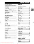
1
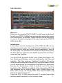
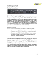
Owner‘s Manual
PRO-12 ASB
PRO-12 ASB is manufactured by CreamWare Audio GmbH, Siegburg, Germany.
(C) CreamWare 1999 - 2005 - all rights reserved.
The following documentation, compiled by CreamWare Audio GmbH (henceforth called
CreamWare), represents the current state of the described product. The documentation
may be updated on a regular basis. Any changes which might ensue, including those
necessitated by update specifications, are included in the latest version of this documentation. CreamWare is under no obligation to notify any person, organization, or institution of such changes or to make these changes public in any other way.
We must caution you that this publication may include technical inaccuracies or typographical errors.
CreamWare offers no warranty, either expressed or implied, for the contents of this
documentation. You will find the warranty regulations for the product at the end of this
documentation.
In no event will CreamWare be liable for any loss of data or for errors in data use or
processing resulting from the use of this product or the documentation. In particular,
CreamWare will not be responsible for any direct or indirect damages (including lost
profits, lost savings, delays or interruptions in the flow of business activities, including
but not limited to, special, incidental, consequential, or other similar damages) arising
out of the use of or inability to use this product or the associated documentation, even if
CreamWare or any authorized CreamWare representative has been advised of the possibility of such damages.
The use of registered names, trademarks, etc., in this publication does not imply, even in
the absence of a specific statement, that such names are exempt from the relevant
protective laws and regulations (patent laws, trademark laws etc.) and therefore free for
general use. In no case does CreamWare guarantee that the information given in this
documentation is free of such third-party rights.
Neither this documentation nor any part thereof may be copied, translated, or reduced to
any electronic medium or machine form without the prior written consent from CreamWare
Audio GmbH.
This product (and the associated documentation) is governed by the GTC (General
Terms and Conditions) of CreamWare Audio GmbH.
Index
Owner’s Manual PRO-12 ASB
Disclaimer
Index
Intrduction
Getting started
Making connections
Power adaptor
MIDI connection
Audio connection
Power switch
USB connection and drivers
Installation of Remote-software
Presets
The Configuration-Strip
Match
Value
MIDI
Sound
Presets
Effects
Effect programs / Parameters
The Control Panel
Oscillator A & B
Filter Section
Amplifier
LFO / Modulation
Glide / Unison
PRO-12 ASB Remote-Software
General information
The panel´s layout
Main-page
Add-page
Prefs-page, Hardware Info
Effects Page
MIDI Monitor, MIDI keyboard
Preset administration
Specifications
MIDI implementation table
Specifications
Warranty regulations
CE certification
02
03
04
05
05
05
06
06
06
07
08
09
09
10
10
10
11
12
13
15
16
18
21
22
22
22
23
28
31
33
34
36
37
38
38
3
Introduction
Welcome
Thank you for choosing PRO-12 ASB. You will have just as much
fun with your PRO-12 ASB as we had when developing this unique
and characteristic Synthesizer. Please read the manual thoroughly
in order to fully take advantage of the many features the PRO-12
ASB has to offer.
Introduction
From todays view the configuration of the PRO-12 ASB can be
described as classic style. Two multifunctional Oscillators are used
as sound source, which can access various waveforms - even at
the same time. The Oscillators are mixed with White Noise within
the Mixer Section, followed by the 24dB Lowpass-Filter with Resonance and the Amplifier.
You will find two Envelope curves, both of them with Attack, Decay, Sustain and Release, which are dedicated to the Filter and
Amplifier. The Filter envelope, Oszillator B and the LFO can be
routed to different Modulation targets. By using te Modulation Wheel
you will experience a lot of interesting Combinations of Modulation
Sources and Destinations, which is certainly one of the major
highlights of the PRO-12. In addition to the Original the PRO-12
was equipped with an Effects Section with Chorus/Flanger and
Delay. Not enough, we thought MIDI Clock Synchrnisation and
Aftertouch would also fit well.
Finally the PRO-12 ASB now comes with 12 voices and provides
amazing results especially in the Unisono mode.
4
Getting started
Making Connections
Connecting the power adaptor
To connect your PRO-12 ASB with the power supply, please use
the power adaptor coming with the PRO-12 ASB. Connect the
power adaptor to your PRO-12 ASB. Before connecting the power
adaptor to the socket, make sure it is compatible to the power
supply system. Upon loss of the power supply, a standard AC or
DC 12V / 1.5 A power supply can be used as a replacement.
The connection to the PRO-12 ASB is made with a hollow plug
(5.5 mm x 2.1mm x 11.5 mm, center positive).
MIDI connections
There are two ways to play your PRO-12 ASB using MIDI:
1. Connect your PRO-12 directly to a master keyboard.
2. Connect your PRO-12 to the MIDI port found on your
computer in order to use it with a sequencer or the
PRO-12 Remote-Software.
Connect the MIDI in and out of your PRO-12 ASB with the MIDI
in and out of your keyboard or computer. The MIDI input of your
PRO-12 ASB has to be connected to the MIDI output of your
keyboard or computer and MIDI output of the PRO-12 ASB with
the MIDI input of your keyboard or computer.
The incoming MIDI signal can also control another instrument
via MIDI thru. If your computer does not have a MIDI port, you
can use the USB connection as an alternative.
5
Audio Connections
In order to obtain sound output, you may either connect the MINIMAX ASB stereo outputs to a mixer’s inputs, computer’s inputs
or HiFi stereo input.
You can also process an external signal
by connecting an external source to your
MINIMAX ASB input.
Power Switch
In order to operate the MINIMAX ASB please
turn the power switch on.
USB Connections and driver installation (Windows XP)
Rather than using MIDI to
connect your PRO-12 ASB to
a computer, you can use the
implemented USB interface.
To utilize this function, you
will need the Windows Service Pack 2.
After connecting the PRO-12
to a computer, windows will
automatically recognize the
PRO-12 ASB as an audio
USB instrument. No extra
drivers are required for this
device. You can start playing
right away! After starting your
sequencer program (here:
CubaseSX), you can use the USB audio instrument driver as a
MIDI port. In very few cases, you may encounter that under
older versions of Windows XP (before Service Pack 2), the USB
port will not show availability after disconnecting the PRO-12
ASB. In this case, please reboot Windows XP. After rebooting,
your USB port will show availability again.
6
Installation of the Remote-Software
To install the Remote-Software coming with the MINIMAX ASB on
your PC, please put the CD-ROM with print MINIMAX ASB into the
CD-R drive of your Computer. The Install Dialog should then appear
on your screen automatically. In case you have de-activated the
automatic Start-function of your CD-R
drive, please start the installation by
double clicking the file „setup.exe” on
the CD.
Within the first dialogue please choose
the language used within the install procedure and then, confirm your choice by
pressing the „Next“ button.
You will next see the „Welcome to the Installation“ Dialog – please
confirm by pressing
„Next“.
In the following you will find the license agreement. Please read carefully and choose „ I accept the license terms“ if you agree and go the
next dialog by pressing „Next“ button then.
You can now choose the installation path by defining it within the
drop down menu „Installation path“. If you don’t choose a dedicated
path here, the Remote-Software will be installed to
“C:\Programs\Minimax”. The required empty
space on your hard-disk is 6.7 MB.
Within “Choose Startmenu-Folder” you can decide the directory your
own. Otherwise the directory “Minimax” will be
created and used.
7
In the following dialog you have the opportunity to check your setting once again. If
all settings are correct, please choose install to start the installation process.
The final dialog offers the opportunity to
open the Readme-File with actual information about the MINIMAX ASB and to start
the Remote-Software after installation.
Presets
The Preset administration will be handled within the sound section
of the Configuration-strip. There are 128 user and
128 factory presets. Activate the preset button.
Use the DOWN/UP button or data wheel to scroll
through the presets. A preset holds all parameter and effect adjustments as well as the remote
software’s “Add Page”.
You can only save presets in the User-Bank. This is the
reason why “User” will automatically be selected when saving a preset.
8
Configuration-Strip
The Configuration-Strip is used for System-Adjustments, Preset Configurations and various Display features.
Match
This display shows you all adjustable values for
every parameter of the chosen preset . Turn a
knob long enough so the LED (PRESET) in the
middle blinks. If the changed value is smaller than
the one in the Preset, then one of the three LEDs
(left) will light up. Should the value be greater,
then one the first LEDs (right) will light up. In this
respect, you can easily make out the Preset’s
value.
Value
With the Data-Wheel (on the left) and
the DOWN/UP buttons you can set
the parameters of the Configuration
Strip, like i.e. MIDI-Channel or
Volume. Choose between the monophonic / polyphonic mode by pressing
DOWN and UP button at the same
time (MONO/POLY). The display will show “of” for monophonic
and “on” for polyphonic mode.
9
Midi
Activate the CHANNEL button in order to select the desired MIDI
channel with the DOWN/UP buttons or Data Wheel.
If a small vertical line appears under the channel
number, this means the instrument receives MIDI
data on all channels (Omni-Mode). Midi data will be
sent though, on the selected channel. Without the
line, the instrument receives and sends MIDI data
on the selected channel.
Midi Values:
MIDI Channel 1 … 16 Omni Off
MIDI Channel I1 … I16 Omni On (Vertical Lines)
Activate the CONTROL button in order to select the desired MIDILocal-Modus with the DOWN/UP buttons or Data Wheel. “Local
Off” is on when the display shows “of” and “Local On” on when
showed “on”. In Local Off Modus all local controllers are set to off.
Sound
Activate the VOLUME button to change
the volume with the DOWN/UP buttons or
Data Wheel. This is the main volume for
the complete hardware will not be saved
within a preset.
Preset
Activate the PRESET button in order to select the desired Preset
with the DOWN/UP buttons or Data Wheel. A Preset withholds all
adjustments, “Add Page” parameters of the Remote Software and
Effect adjustments. Presets can only be saved in the User Bank,
reason why “USER” will automatically be selected when saving a
preset.
Activate the USER button in order to switch between Factory and
User-Bank. Please note, that you can only switch, when PRESET
has been activated.
10
Presets ff.
The second function of the USER button will be
activated by pressing for longer time. In this case
all visible parameters of the hardware will be stored
as they are. Invisible parameters will be set to
their basic value.
Activate the STORE button to save a preset. The LED starts blinking.
Now choose a preset number either by turning the Data-Wheel or by
using the UP/DOWN buttons and then press STORE again. On this the
LED start flickering – please press STORE button until the LED turns off.
The preset is now stored under the chosen preset number.
Effects
Activate the BYPASS button to bypass any effects. Depending on your
adjustments made the signal without effects might be a little bit louder
than with effects turned on. On activated BYPASS the LED will be lightened and no effects are being heard. Pushing the button again will then
deactivate the bypass function again.
Activate the PROGRAM button to choose the desired effect algorithm by using the Data-Wheel or
with the UP/DOWN buttons. In total you can choose between 5 modes for the two effects (Chorus &
Delay). The parameters for the effects (PARAM 1
to 3) are different for every program.
11
Effect programs:
PARAMETER 1
PARAMETER 2
PARAMETER 3
Chorus
Chorus Depth
Chorus Rate
Chorus Feedback
Delay Time
Delay Damping
Delay Time Left
Delay Time Right
Delay BPM
Delay BPM
Delay Note Left
Delay Note Right
Chorus Delay Time
Chorus Depth
Delay Time Left
Delay Time Right
Chorus Delay BPM
Delay BPM
Delay Note Left
Delay Note Right
Value range of Parameters:
C ontrol R ange
C horus D epth
C horus R ate
C horus Feedback
D elay Time
D elay B P M
0 - 10
0.01 Hz - 20 Hz
-5 - 5
0.3ms - 1,4860s
72 - 192
1/1 1/2P 1/2 1/2T 1/4P 1/4 1/4T
D elay N ote
1/8P 1/8 1/8T 1/16P 1/16 1/16T
1/32P 1/32 1/32T 1/64P 1/64 1/64T
12
Control Panel
Oscillator A&B
The Oscillators A&B are mainly identic except some few differences.
Turning the wheel allows you to add various waveforms to the oscillator
signal. With Oscillator A you can apply Saw Wave and Pulse, with the
Oscillator B you can choose between Saw Wave, Triangle and Pulse. All
waveforms can be activated at the same time, which allows a mix of up to
5 oscillator waveforms in parallel. You can adjust the Pulse range manually or via modulation. If Oscillator B is used as Modulation source, you can
disconnect its signals from the keyboard. Additionally you can downscale Oscillator B to lower freqency bands,
which allows to use it as an typical
LFO. Oscillator A can be synchronized with Oscillator B.
Frequency
Here you can detune Oscillator A with Osciallator B. By detuning both
Oscillators and then mixing them, you will recognize Schwebungen, and
the sound will appear more vital. The range can be adjusted with one
octave.
Saw wave On/Off:
Switches the Saw Wave of the assigned Oscillator on/off.
Pulse On/Off:
Switches the pulse wave of the assigned Oscillator on/off.
Triangle On/Off
As Oszillator B can also be used as an LFO, it is additionally equipped
with a triangle waveform. ere you switch Triangle waveform on/off.
13
Pulse Width
Adjust here the pulse range of the assigned Osczillator manually. To hear
the resulting sound, the pulse width has to be activated. The range
reaches from app. 5% up to 100% of the pulse width. Modulation of the
Pulse width is described within the chapter „modulation“.
Sync On/Off
Activates the Hard Sync of Oszillator A to Oszillator B. With the Hard
Sync the waveform of Oscillator A will be restarted with every finalized
period of Oscillator B. This way the tone of Oscillator B will be transferred
to the Osczillator A. Depending on the Octave- and Frequency adjustments of Oscillator A you will get very differing effects, which tangle the
spectrum of the Oscillator.
LoFreq/Normal
Here you downscale Oscillator B to very low frequencies and Oszillator
now swings much slower. By using the Modulation Matrix you can now
use Oscillator B as an LFO additionally.
Keyboard
By using the Keynoard function you can disconnect Oscillator B from the
connected keyboard. The Oscillator now no longer follows the note played, but swings only on the frequency adjusted with „Octave, LoFreq and
Frequency“. This way you can use the Oscillator as modulation source
with adjustable frequency.
Audio Mixer
Within the Audio mixer section you mix
the signals, before they are released to
the filter. You have one assigned volume
control for each Oscillator A and also the
Oszillator B.
The third volume control regulates the volume of the noise signal (in this case white noise).
At the Add-Page of the Remote software you will also find an
additional volume control for external signals.
14
Filter Section
The filter section consists of a lowpass Filter which can be modulated
with resonance which reaches the Eigenresonanz. Together with the
envelope curve and other modulations the lowpass filter defines the
sound behaviour over time. The lowpass shows a Flankensteilheit of
24dB per Octave. All frequencies below the cutoff frequencies will stay
untouched. The frequencies above the cutoff frequency will be abgesenkt with 24dB/Octave. The Resonance is created by feedback between
Filter input and Filter output, while frequencies around the region of the
cutoff frequency are empowered.
To modulate the Filter you can
use an assignable envelope
curve, the keyboard and the
sources of the modulation
matrix.
Cutoff:
Cutoff Frequency describes
the frequency, above which the
spectrum is cutted and overtones are reduced. You can adjust the cutoff
frequency manually.
Resonance
Here you find the resonance parameters. Resonance is created by feedback of the Filter input with the Filter output, while the frequencies around
the adjusted cutoff frequencies are empowered. On full Resonance the
Filter swings in Eigenresonanz and gives a sinus tone at the defined
cutoff frequency. The Filter is therefore also looked upon as additional
sound source.
Envelope Amount:
Here you can adjust the intensity of the envelope curve. The Cutoff now
follows the envelope curve with the adjusted intensity and this way creates a Klangverlauf entsteht. Starting and End point of the envelope
curve over time is the adjusted Cutoff Frequency.
Keyboard Amount:
By activating Keyboard Amount the Cutoff-Frequency follows the played
tone with the adjusted intensity.
If the control stays at value „7“ on the scale, the frequency
follows at 100% which means that with every otave the cutoff
frequency will have the double value.
15
Amplifier
Together with the envelope curve the Amplifier defines the volume Verlauf of the sound. For Modulation of the Amplifiers you can use the
ADSR-envelope curve. The Volume Control is part of this section.
Attack
defines the duration of the first envelope curve segment. Within the given
Attack Phase the envelope curve increases within the given time to the
Maximum value.The intensity of the increase is defined by Envelope
Amount. The Maximum is defined both by Cutoff Frequency and also the
Envelope Amount.
Decay
This describes the duration of the second envelope curve segment.
Within the deacy phase the envelope curve falls within the adjusted time
to the value adjusted under Sustain.
Sustain
is the value, on which the envelope curve stays after Decay.
Release
Within the Release Phase the envelopecurve falls back within adjusted
time to the Minimum value. The Minimum value is defined by cutoff.
Velocity
Modulation of all levels of the envelope curve depending on how intense
or less intense the keyboard is played. Depending on the Modulation
intensity settings the Pegel of the envelope curve vary between Minimum and Maximum. The Anschlagsstärke influences the coloration of
sound.
16
Options for Amp- and Filter Envelope
ADR
Activate this option to set Sustain to zero. This way you
can switch very quickly between percussive sounds
and Sustain based soundswithout having to adjust or
change the Sustain level each time.
Release
Activate this option to set Release time to zero.
Volume
Here you can adjust the master volume for the Synthesizer. As this wheel also regulates the volume of
the instrument before effects passing, you can also
use it to meter the implemented effects, i.e. to avoid
distortion when using the Flanger with a lot of feedback.
17
LFO
The LFO of your PRO-12 ASB features three different wave forms, which
are the same used within Oscillator B. Choosing the desired waveform
can easily be done with the three LED push buttons. You can activate all
waveforms one by one, all at the same time or in any combination you
like, which can lead to very interesting results. Destination and intensity
of the LFO have to be defined within the Modulation Matrix.
Besides the features provided by the
Original you will find additional parameters on the Add-Page of Remote
Software. There you will be able to
sync the LFO to an external MID clock.
Also restart of the LFO can be activated with the keyboard this way.
LFO Frequency
Here you can adjust the frequency of the LFO.
Saw wave On/Off
Switches te saw wave on/off.
Pulse On/Off
Switches Pulse wave on/off.
Triangle On/Off
Switches Triangle wave on/off.
18
Modulation
PRO-12 ASB comes with three modulation sources - Filter Envelope,
Osczillator B and LFO - which can be combined with and routed to five
different destinations - Frequency Oszillator A, Pulsewidth Oszillator A,
Frequency Oscillator B, Pulsewidth Oscillator B and Filter Cutoff.
You can connect sources and destinations directly or via the modulation
wheel within the PRO-12 ASB. Thus you have two different modulations
busses. The basic intensity will be adjusted initially for each source.
When intensity is adjusted by the modulation wheel this additionally
influences the modulation depth. The Filter Envelope and Oscillator B are
polyphonic Modulation sources, which means that they influence per
each voice. The LFO is a monophonic modulation source and thus can
only influence single sounds.
Poly Mod
Within this section you adjust the intensity of the modulation sources
Filter Envelope and Oscillator B and activate one or multiple modulation
destinations.
Source Amount
Filter Env
Here you adjust the modulation depth of
Filter Envelope for all defined destinations.
OSC B
Here you adjust the modulation depth of
Osczillator B for all defined destinations.
LFO Amount
Here you adjust the modulation depth of
the LFO for all defined destinations.
19
Destination
Freq A
Activate this button to set the Modulation Signal of Oscillator A .
Freq B
Activate this button to set the Modulation Signal of Oscillator B.
PW A
Activate this button to set the Modulation Signal of the pulse width of
Oscillator A .
PW B
Activate this button to set the Modulation Signal of the pulse width of
Oscillator B.
Filter
Activate this button to set the Modulation Signal of the Filter.
Wheel Modulation
The intensity of the Wheel Bus within the Modulation Section is generally
adjusted and controlled by the Modulation Wheel. In fact within the Original this has been the only way to control the Wheel Bus. To provide more
advanced options for control and adjustment you will find aditionally
Controls for Modulation Intensity and Modulation Offset. Furthermore
also the Intensity of the Pitch Bender can be adjusted now. You will find
the parameters on the Add-Page within the Remote-Software.
20
Glide
By using the Glide function a played note will glide into the next note
following fluently within the time defined by turning the glide wheel.
Glide
Here you define and set the time, in which the played note glides into the
next following note. The Glide function doesn‘t have to be separately
activated to work, you only have to use the glide wheel to activate this
funtion. If the glide wheel is set to zero position, no glide will occur.
Unison
You can activate the Unisono-Mode here. This offers you the opportunity to have one note played
with multiple voices, which leads to very wide sound
beds. More parameteres can be accessed within
the Add-Page of the Remote-Software.
21
PRO-12 ASB
Remote Software
General
To control your PRO-12 ASB via the Remote-Software, you have to
connect the PRO-12 ASB via USB or MIDI with a Computer.
The Panel’s Layout
The Remote-Software offers you different pages for operation. The
Main-Page shows the surface of the PRO-12 ASB and you will find
all parameters which you already know from the hardware. On the
Add-Page you will find parameters which are not easy to control via
the PRO-12 ASB hardware or even not accessible at all.
This includes Aftertouch behavior, effect settings and the settings
for the Modulation Wheel. The Prefs-Page offers system settings of
the Remote-Software and also a function to update your PRO-12
ASB operation system at given time.
On the bottom of the Remote-Software you can access all elements
to administrate Presets, the integrated virtual MIDI-Keyboard and
also a MIDI-Monitor, which enables you to screen and control incoming MIDI-messages.
22
More details
As the functions you can access on the Main Page are identical to the
hardware behavior and have been described within the first chapters of
this manual, the focus of this chapter lies on the additional functions of
the Remote-Software.
The ADD PAGE
Keyboard Mode
Retrig/Normal
Here you can define the Trigger behaviour of the
envelope curves. Within the mode „normal“ the
envelope curves are not restarted upon the voice
stealing. Playing a Legato is herewith possible,
without having the envelope curve triggered with
every note. Within the mode „Retrigger“ envelope
curves will be restarted on voice stealing any case,
so that percussive sound i.e. keep their attack, even if they are played in
Legato.
Low Note/Last Note
Switches on/off the Low-Note or Last-Note-Priority. At Low-Note-Priority
deeper tones have priority against high tones and a high note can‘t steal
a deep note. If Last-Note is activated, always the last note is played.
Together with the Trigger-Modi on the Main Page this opens interesting
possibilities and influence on the settings of both voice stealingand envelope curve start.
Single On
If you activate „Single On“, the instrument plays back one voice, no
matter how many voices are active. Thus the correct playback of Solo
Sounds with Glide is possible.
23
Aftertouch
The Original never had an Aftertouch to adjust Modulation. The Aftertouch Section implemented within the PRO-12 ASB has been designed
after a similar section within the T8 model. Other than within the T8
model the PRO-12 works with one-channel Aftertouch and not with Key
Aftertouch. This means, that if Aftertouch is sent by one Taste the referring modulations will be sent to all played voices.
Pitch Osc A/B
The intensity and direction of modulation towards both Oscilllators tone
character can be adjusted here. You can thus control the Pitchbend of the
Oscillators via Aftertouch.
Freq A
Actvates the Modulation for Oscillator A.
Freq B
Activates the Modulation for Oscillator B.
PW
Intensity and direction of Pulse width Modulation of the Oscillators.
PW A
Activates Pulse Width for Oscillator A.
PW B
Acivates Pulse Width for Oscillator B.
Filter
Intensity and Direction of Modulation twoards Intensität und Richtung
der Modulation auf den Filter Cutoff. This way you can also create Filterweeps via Aftertouch.
Amp
Intensity and direction of Modulation towards volume.
MW Amp
Intensity and direction of Modulation via Modulation Wheel.
24
LFO Freq
Intensity and direction of Modulation towards LFO Frequency.
Time Velocity
You can modulate the envelope curve times via velocity here.
Filter Envelope
Attack
Define Intensity and direction of Attack time Modulation via velocity here.
Dec/Rel
Define Intensity and direction of Decay or Release times Modulation via
Velocity here.
Amplifier Envelope
Attack
You can define Intensity and direction of Attack time towards the Amplifier Envelope here.
Dec/Rel
Define Intensity and Richtung of Decay or Release times towards the
Amplifier Envelope here.
25
MIDI Clock Settings
Withi the MIDI Clock Settings you can adjust the MIDI-Tempo and define,
if the instrument shall be synced to internal or external MIDI Clock.
External
Switches between internal and external MIDI Clock sync.
Course/Fine
To adjust and show the Tempo, you will find two text fields. The first one
shows values in BPM (Beats per Minute) and the second shows the
values in 1/100s BPM.
BPM
Here you can adjust the Tempo of the internal MidiClock in BPM.
LFO Settings
Retrig
Here you can choose between the „Retrig“ and „Free Run“ Modus. Within
the Modus „Free Run“ the LFO runs free of beaks. Within the Modus
„Retrig“ the LFO will be restartet/retriggered by pressing a Keypad within
the chosen phase.
Phase
Define the Phase, the LFO will be restartet with activated „Retrig“.
MIDI
You can choose here, if the frequency of the
LFO shall be set manually by turning the Wheel
or via MIDI and note length.If MIDI is activated, you will find a Drop-Down-Menue with several values of note length, from which you
can choose. The length of the chosen note will
define the time period of the LFO.
26
Wheel MOD
MW Intensity
Maximum Intensity of the Wheel-Bus within the Modulation Section, while the maximum Modulation is set with the Modulation Wheel.
MW Offset
General Intensity of the Wheel-Bus within the Modulation Section. Depending on your Offset settings you can strengthen the modulation additionally with the Modulation Wheel.
Bend Range
Here you adjust the maximum Detuning of the instrument in half tones by
Pitchbend. The value range is between 0 up to 24 half tones.
Unisono
Voices
Here you define, how many voices shall sound in parallel when pressing
one Keypad.
Detune
Define the detuning between the chosen number of voices.
27
PREFS PAGE
On the PREFS and EFFECTS pages you can edit the system settings of
your PRO-12 ASB.
MIDI IN
Device
Here you can choose the desired MIDI or USB port, the Pro-12 ASB is
connected to with your Computer.
Channel
Here you choose the MIDI channel, through which you want to control
your PRO-12 ASB (both ways for Midi In and Midi Out)
MIDI OUT
Here you can choose the desired MIDI or USB port, the Pro-12 ASB is
connected to with your Computer.
Please make sure, that you have adjusted both MIDI in and also
MIDI out properly.
28
Hardware Info
Within this section you will find further information on your PRO-12 ASB
hardware, which you might need upon firmware updates.
Device
Name of the connected unit
Version
Version number of the Firmware
Serial Number
Serial number of your MINIMAX ASB
Refresh
will update the information on the connected unit
Firmware Update
This feature enables you to equip your PRO-12 ASB with actual software
programs when available.
Activation Key
Please enter here the Activation
Key of your PRO-12 ASB.
Firmaware Source File
Displays the chosen Update-file.
Browse
Select the directory, where the update file is located.
Write
Push the "Write" button to install the Update to your PRO-12 ASB.
29
EFFECTS PAGE
The Effects-Page offers controls for the Chorus and Flanger Effects
implemented within your PRO-12 ASB.
Chrous/Flanger
Select Chorus or Flanger Algorithm.
Rate
Here you adjust the Modulation Velocity.
Depth
Here you adjust the Intensity of Modulation.
Phase
Here you adjust the Phase of Modulation.
Feedback
Here you adjust the Intensity of the Feedback.
Dry Wet
Here you adjust the ratio of the effects mixed to the signal.
30
Wirhin the DELAY SECTION you will find controls for adjustment of the
implemented Delay Effect.
Left Cannel
Here you adjust the Delay setting of the left channel.
Right Channel
Here you adjust the Delay settings of the right channel.
Time
Here you adjust the time of the Delay. If BPM is activated, you can enter
the value in note length and set time in milliseconds as standard.
Feedback
Here you adjust the ratio of Feedback in the Delay chain, which will affect
the number of echoes, you receive.
Damp
Here you can adjust the Intensity of treble damping.
Level
Here you adjust thevolume level for left and right channel.
Tempo
Here you can enter the value for the Delay-Tempo in BPM.
Dry Wet
Her you adjust the ration of Effects withn your mix.
31
MIDI MONITOR
You can enter the MIDI-Monitor by pressing the MIDI-Monitor button on
the right side of the Remote Software. The MIDI-Monitor allows you to
check incoming and outgoing MIDI-messages.
Controls
Clear
removes the shown values within the MIDI-Monitor.
Pause
sets MIDI messages on hold.
Hex
dosplays the values as a Hexadecimal number.
Realtime
displays the Realtime values like i.e. MIDI-Timecode.
SysEx
When activated also SysEx (System Exclusive) data will be shown within
the Midi Monitor. Please note, that SysEx data may vary, as these are
manufacturer specific data, which allow data transfer besides the MIDI
standard protocol.
32
MIDIKEYBOARD
By using the Midi keyboard integrated
in the Remote-Software you can play
PRO-12 ASB without using any external keyboard or Sequencer software –
with computer mouse or your PC keyboard only. You activate the Midi Keyboard by actuating the referring buttons on the bottom of the Remote-Software.
Channel
Here you adjust the Midi channel, on which signals are transferred.
Octave
This function allows you to adjust the note region in octave steps.
Playing with a Computer Keyboard
For using the computer keyboard as Midi Keyboard, please note the
following default settings.
C#
[w ]
C
[a]
D#
[e]
D
[s]
F#
[t]
E
[d]
F
[f]
G#
[y]
G
[g]
A#
[u]
A
[h]
B
[j]
33
PRESET ADMINISTRATION
The integrated Preset Administration within the Remote-Software allows
an easy and comfortable way of storing, exchanging and editing of your
preset lists.
Open Presetlist
öpens the Presetlist.
Open File
ou can open a preset list file. Either you can
save any Preset list as a file for possible
exchange with other users of the MINIMAX
ASB or to create backup copies. The File
extension for Preset lists is *.pre. By using
the arrows beneath the Preset button you
can step through your presets.
The Preset Bank
To save a preset to your computer, you have to create a bank. If no bank
is existent or you want to create additional banks, please choose “create
bank” from the dropdown menu. For changing the name of an existing
bank please press “F2” while having selected the bank of your choice.
Now you can enter the desired name. When finished, press enter. The
new bank name is stored now.
34
Storing, deletion and changing of Presets
To store a preset, please create a new entry by using “create” from the
dropdown menu. After having created a new entry, you can store the
preset by choosing “save”.
Obviously already existing presets can be
replaced this way also.
By choosing “Restore” you can load an existing preset and use it again.
With “New File”, “Open File”, “Save File” and
“Save File as” you can edit any file from the
list of presets. Additionally you can store any
preset data to your hard-disk and thus exchange it with other users.
The used file extension is *.pre
Upload of Preset files
To exchange presets between the MINIMAX ASB Hardware and Remote-Software you will find four options under the menu "box":
Upload of Preset files
To exchange presets between the PRO-12 ASB Hardware and RemoteSoftware you will find four options under the menu "box":
Upload Use Bank to Box
This function ports the data within the User-Bank from Remote-Software
to PRO-12 ASB
Upload Factory Bank to Box
This function ports the data within the Factory-Bank from Remote-Software to PRO-12 ASB
Upload Use Bank from Box
This function ports data of the User-Bank within your PRO-12 ASB to the
Remote-Software
35
C C
0
1
2
3
4
5
6
7
8
9
10
11
12
13
14
15
16
17
18
19
20
21
22
23
24
25
26
27
28
29
30
31
32
33
34
35
36
37
38
39
40
41
42
43
44
45
46
47
48
49
50
51
52
53
54
55
56
57
58
59
60
61
62
63
P a r a m e te r
B a n k S e le c t
M o d u la t io n
U n is o n vo ic e s
U n is o n D e t u n e
G lid e T im e
D a ta E n try
D e vic e V o lu m e
L F O S e t t in g s R e t rig
L F O S e t t in g s P h a s e
V o lu m e
O s c A F re q u e n c y
O s c A S hape S aw
O s c A S h a p e P u ls e
O s c A P u ls e W id t h
O s c A S y nc
O s c B F re q u e n c y
O s c B F in e
O s c B S hape S aw
O s c B S h a p e T ria n g le
M a s te r Tu n e
O s c B S h a p e P u ls e
A ft e r t o u c h P i t c h
B end R ange
O s c A V o lu m e
O s c B V o lu m e
O s c B P u ls e W id t h
O s c B L o F re q
O s c B K e y b o a rd
A ft e r t o u c h D e s t F r e q A
A ft e r t o u c h D e s t F r e q B
B a n k S e le c t
N o is e V o lu m e
A ft e r t o u c h P W
A ft e r t o u c h M W A m t
E x t e rn a l V o lu m e
A ft e r t o u c h D e s t P W A
A ft e r t o u c h D e s t P W B
K e y b o a rd A m o u n t
C u t o ff
R es onanc e
E n ve lo p e A m o u n t
F ilt e r E n v A t t a c k
F ilt e r E n v D e c a y
F ilt e r E n v S u s t a in
F ilt e r E n v V e lo c it y
F ilt e r R e le a s e
A ft e r t o u c h L F O F e q
R e le a s e
A ft e r t o u c h F i lt e r
A ft e r t o u c h A m p
A m p E n v A tta c k
A m p E nv D ec ay
A m p E n v S u s t a in
A m p E n v V e lo c it y
M W In t e n s i t y
M W O ffs e t
P o ly M o d O S C B
A D R
K e y b M o d e R e t rig
L o w N o te
A m p E n v R e le a s e
P o ly M o d F ilte r E n v
C C
64
65
66
67
68
69
70
71
72
73
74
75
76
77
78
79
80
81
82
83
84
85
86
87
88
89
90
91
92
93
94
95
96
97
98
99
100
101
102
103
104
105
106
107
108
109
110
111
112
113
114
115
116
117
118
119
120
121
122
123
124
125
126
127
P a r a m e te r
S u s ta in P e d a l
S o s te n u to
S o ft P e d a l
S in g le M o d e
U n is o n
D ry /W e t
R a te
P hase
D e p th
F eedbac k
P o ly M o d D e s t in a t io n F re q A
P o ly M o d D e s t in a t io n F re q B
P o ly M o d D e s t in a t io n P W A
P o ly M o d D e s t in a t io n P W B
P o ly M o d D e s t in a t io n F ilt e r
D ry /W e t
T im e L e ft
N o t e L e ft
F e e d b a c k L e ft
D a m p L e ft
L e v e l L e ft
B P M L e ft
LF O S hape S aw
L F O S h a p e T ria n g le
L F O S h a p e P u ls e
C ro s s
T im e R ig h t
N o t e R ig h t
F e e d b a c k R ig h t
D a m p R ig h t
L e ve l R ig h t
B P M R ig h t
L F O F re q u e n c y
B y pas s
P ro g ra m
C h o ru s / F la n g e r
W h e e l M o d F re q A
W h e e l M o d F re q B
W heel M od P W A
W heel M od P W B
W h e e l M o d F ilt e r
B P M
W h e e l M o d S o u rc e M ix
E x te rn a l S o u rc e
L F O S e t t in g s M ID I
T im e V e lo c it y A t t a c k F ilt e r E n v
T im e V e lo c it y D e c / R e l F ilt e r E n v
T im e V e lo c it y D e c / R e l A m p E n v
T im e V e lo c it y A t t a c k A m p E n v
A l l S o u n d s O ff
L o c a l C o n t r o l O ff
A l l N o t e s O ff
O m n i O ff
O m ni O n
M ono O n
P o ly O n
36
Specifications
Analog Outputs
Asymmetric
2 x jack 6,3mm
Analog Inputs
Asymmetric
2 x jack 6,3mm
Connections
MIDI
USB-Port
DIN-5-Pol, In, Out, through
Full Speed Rev. 1.1
General
Power Input
Dimensions
Weight
Number of Voices
Sampling Rate
Resolution
>20 W
4 x 21 x 5 (front) / 8 (back)
3.4 kg
6
44.1 kHz (internal oversampling)
32 bit
37
Warranty Regulations
The hardware described within this documentation and the warranty regulations are governed by and granted according to German Law.
CreamWare Audio GmbH (“CreamWare”) warrants, that the described product has been
free of failures within parts or components of the hardware and was found to be fully functional.
Any single units has been checked by Quality Assurance Department several times and with
various measures, before this product has been delivered to you. Therefore please carefully
read the following information, which are important in the case of probable damages or
malfunctions:
If goods are being found defective, missing features described within the present documentation or becoming defective due to eventual fabrication deficiency or material defects within
the first six months after purchase, then CreamWare shall at its sole discretion and evaluation
replace or repair the defective parts or goods. Multiple repairs shall be permissible. In case
the malfunction or physical failure can not be fixed, customer receives the right to refrain
from the purchase with refund of the amount originally paid for the defective product.
Within the time frame of 6 to 24 months customer has to provide proof, that the claimed
malfunction or defective part or component has already been defective upon first delivery. In
this case CreamWare will execute required repair or replacement at no cost upon acceptance
of customer’s proof by CreamWare.
Any deficiencies caused by transportation have to be declared within a 14 days period after
receipt of goods by written notice. Please note, that any warranty repair at no cost ruled by
the above regulations requires registration of name and address either online at the “My
Page” area on the CreamWare website (www.creamware.com) or by sending the proof of
purchase together with the defective product.
To return defective goods, please contact the retailer where you purchased the product. As
an alternative you can also contact CreamWare directly to receive the RMA number for the
defective product. PLEASE NOTE: It is mandatory to return the product with the referring
RMA number to avoid delays in repair.
If possible, please also add a description of the failure occurred to enable us executing the
repair as soon as possible.
Non-compliance with the operation and maintenance instructions, any alterations or modifications to the goods delivered, changing or utilizing any parts or materials not conforming
to Sellers specifications will immediately render any warranties null and void.
For a warranty claim, customer has to prove to CreamWare beyond a reasonable doubt that
none of these aforesaid actions caused the goods to be defective or deficient.
CreamWare Audio GmbH
Fon
++49 (0) 2241 59 58 0
Fax
++49 (0) 2241 59 58 57
email
[email protected]
[email protected]
The hardware described within this documentation is herewith
certified to conform to the requirements set forth in the guidelines for electromagnetic acceptability (89/336/EWG)
CreamWare Audio GmbH, November 2005
Wolf Roth
38
CreamWare Audio GmbH
Am Turm 11 - 13
53721 Siegburg
Germany
Tel.: +49 2241 59 58 0
Fax +49 2241 59 58 57
www.creamware.de
www.creamware.com
39