1
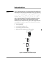
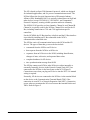
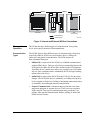
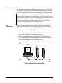
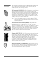
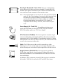
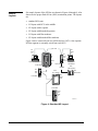
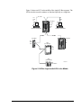
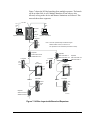
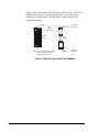
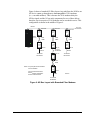
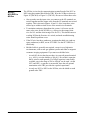
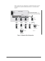
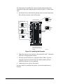
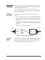
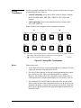
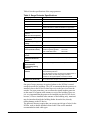
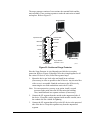
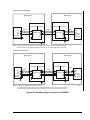
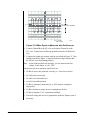
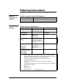
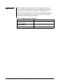
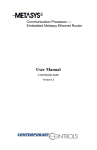
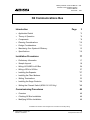
Metasys Network Technical Manual Network Communications Section Technical Bulletin Issue Date 636 1199 N2 Communications Bus lntroduction Page 3 • Application Details *3 • Theory of Operation *5 • Components *8 • Planning Considerations *10 • Design Considerations *11 • Maximizing Your System’s Efficiency • Specifications 13 *15 Installation Procedures 17 • Preliminary Information 17 • Sample Layouts 18 • Wiring--NCU/NEU to N2 Bus 24 • Wiring--ASCs to N2 Bus 27 • Installing the Repeater • Installing the Fiber Modems 31 • Setting Terminations 33 • Installing the Surge Protector *36 • Setting the Channel Switch (NCM 101/102 Only) *48 *27 Commissioning Procedures 49 • Overview 49 • Checking N2 Bus Installation 49 • Modifying N2 Bus Installation 49 *Indicates those sections where changes have occurred since the last printing. © 1999 Johnson Controls, Inc. Code No. LIT-636018 1 www.johnsoncontrols.com Troubleshooting Procedures *51 • Overview • Checking for Good Wire Runs 51 • Checking for Proper Termination 52 • Checking the End-of-Line Device Settings 52 • Checking for Proper Channel Selection 52 • Checking the N2 Device 52 • Checking the Number of Defined N2 Devices 52 • Checking the Length of N2 Bus • Checking for “T” or “Y” Connections 53 • Checking for a Ground Loop 53 • Checking the Repeater 53 • Checking the Surge Protector 53 • Checking the Communication Terminal Board 54 • Checking Communication Faults *51 *53 *55 Ordering Instructions 57 • Johnson Controls Code Numbers 57 • Vendor Code Numbers *57 • Repair Parts *58 * Indicates those sections where changes have occurred since the last printing. 2 Page Network Communications—N2 Communications Bus Introduction Application Details The N2 Communications Bus is a local network that links controllers and point interfaces to the Network Control Module (NCM). The N2 Bus uses a master/slave protocol, in which the master device, the NCM, initiates all communication with the N2 Bus devices. These N2 Bus devices include the Digital Control Modules (DCMs), Point Multiplex Modules (XBN, XRE, XRL, XRM), and all Application Specific Controllers (ASCs). Figure 1 shows an example of several devices connected to the N2 Bus. Note that the N2 Bus is wired in a daisy-chained fashion, in which multiple devices are connected in series. The N2 Bus can use either solid or stranded wire. It can also use optical fiber when special fiber modems are used. Choices include: • 3-wire twisted cable • two twisted pair telephone cable • two twisted pair cable with a shield • duplex optical fiber (requires pair of fiber modems) N1 LAN NCU N2 Bus NEU ASC (ILC Shown) NEU N2EXAMPL Figure 1: Example of an N2 Bus Layout Network Communications—N2 Communications Bus 3 The N2 is based on Opto-22 Optomux protocol, which was designed for industrial applications, and is a proven communication network. The N2 Bus follows the electrical characteristics of Electronics Industry Alliance (EIA) Standard RS-485. It is optically isolated between itself and other devices (except UNT100/101, VAV100/101, and Companion Personal Computer), assuring reliable operation and noise immunity. The NCM101/102 provides two bus channels: Channel A and Channel B. Channel A is typically used for the N2 Bus. Channel B is used for the L2 Bus, including connection to C210 and C260 application specific controllers. For the NCM200, the N2 Bus interface is built-in and the L2 Bus interface is provided by installing an L2 Bus submodule in the NCM’s communications submodule slot. The N2 Bus carries all communication between the NCM and the N2 devices. The types of data that go across the bus include: • commands from the NCM to an N2 device • data requests from the NCM to an N2 device • responses from an N2 device to the NCM, including identification, changes-of-state, advisories, and requested data values • complete databases for N2 devices • time synchronization message from NCM The N2 Bus connects an NCM to other N2 devices either internally or externally. Internally, devices in the Network Control Unit (NCU) are connected to the N2 Bus via the base frame on the NCU (Figure 2). Connection occurs when you plug an N2 device into the NCU. No manual wiring is required. Externally, N2 devices are connected to the N2 Bus via the terminal block on the device or the Communication Terminal Board (TBC) if the connection is at an NCU or Network Expansion Unit (NEU). Connection occurs when you terminate the N2 wires between the terminal blocks and TBCs. Refer to Figure 2. 4 Network Communications—N2 Communications Bus N2 Bus TBC N2 Bus TBC TBC DCM XM NCM XM DCM DCM XM DCM Base Frame Base Frame Base Frame 5-slot NCU 2-slot NEU 1-slot NEU External Wiring Internal Wiring ASC (ILC Shown) INOUTCON Figure 2: Internal and External N2 Bus Connections Theory of Operation The N2 Bus has three different types of communication, four priority levels, and a specific method of data transmission. Communication Types The N2 Bus features three different types of communication, which may come from either an NCM or any user interface device: offline poll, online poll, and general communication. The NCM initiates all three communication types. • Offline Poll--a request from the NCM to re-establish communication with an offline device. This type of poll occurs continually between the NCM and each offline N2 device that is defined in the NCM database. An offline device is polled once after every complete scan of all online devices. Once communication is established, the NCM begins sending online polls to the device. • Online Poll--a request from the NCM to the N2 device for any status changes. The NCM polls devices continually, according to the priority levels assigned to the devices. Polling is interrupted momentarily when a command is issued through general communication. • General Communication--commands and requests that come from application programs or operator devices. These can occur anywhere on the network. This type of communication takes precedence over polling. After general communication finishes, polling of online and offline devices resumes. Network Communications—N2 Communications Bus 5 Priority Levels There are four priority levels assigned to N2 devices: 0, 1, 2, and 3, where 0 is the highest. The priorities establish how often a device is to be polled. For example, a Priority 2 device will be polled more often than a Priority 3 device. How often a device will be polled depends on its assigned priority. You set the priority level when defining the N2 device. We recommend the priority levels remain the system defaults (e.g., DCMs at Priority 1 and ASCs at Priority 3). However, you may assign higher priorities to a limited number of devices if your application requires faster response times. For details, refer to Guidelines for Efficient Operation Technical Bulletin (LIT-636341) under the Appendix tab of this manual. Data Transmission Figure 3 illustrates how a data request from an Operator Workstation (OWS) travels over the N1 Local Area Network (LAN) and the N2 Bus. Figure 3 shows that the request is made at the OWS: 1. The request is created at the OWS. 2. The message is transmitted over the N1 LAN to the NCM that has this object defined. The NCM reformats the message. 3. The NCM sends the message over the N2 Bus to the appropriate device to obtain the requested information. The N2 device responds. 4. The NCM sends the data to the requesting OWS. 5. If the N2 device in the request loop is offline, the NCM notifies the OWS. Operator Workstation NCM N2 Device 1 N1 LAN 2 5 3 4 N2 Bus DATAREQ Figure 3: Data Request from OWS 6 Network Communications—N2 Communications Bus To take this example one step further, suppose a point object at an N2 device changes state and needs to notify you at the OWS. As mentioned before, the NCM continually polls all N2 devices over the N2 Bus for changes in status. When a change occurs, the NCM will be sent that change when it polls the N2 device. The NCM then formats a Change-of-State (COS) message and sends it over the N1 LAN to the OWS (and other devices in the NCM’s routing table for that particular COS message). Network Communications—N2 Communications Bus 7 The components of the N2 Bus are the N2 Bus Submodule (NCM101/102 only), communication terminal board, repeater, enclosure, fiber optic modem (optional), cable, and surge protector. Components N2 Submodule (NU-N2B101-0)--The N2 Submodule is a small plug-in unit for the NCM101 and NCM102. (The NCM401 can also use this submodule if for some reason it is no longer used as a migration NCM.) It is an interface device that the NCM101/102 requires to communicate over the N2 Bus. The N2 Submodule is required for every NCM101/102 that communicates with any N2 device, regardless of whether the N2 device is within the same NCU or remote from the NCU. Note: The NCM200 contains a built-in N2 interface and the NCM401 does not use the N2 Bus Submodule when the NCM401 is used for migration applications. TB2 1 2 5 3 1 4 TB1 6 2 4 5 3 6 Communication Terminal Board (TBC821)--This module is the termination point for the N2 Bus and L2 Bus. (The old TBC model, TBC801, also terminates the N1 LAN via two coax connectors. It is shown in Figure 10.) It allows an NCM to communicate with NEUs and ASCs. The board is factory mounted, and is located in the upper left corner of the 5-slot and 2-slot unit, and on the left side of the 1-slot unit. Every NCU and NEU contains a communication terminal board. Repeater (4683-TTM-1/2)--The N2 Bus repeater isolates and boosts the power of the N2 Bus signal, which extends the range and increases the number of devices that can reside on the N2 Bus. You need a repeater only when the N2 Bus must be extended beyond 5000 feet or beyond 50 devices. The repeater actually creates a new N2 Bus segment. (A segment is an electrically continuous daisy-chained cable between repeaters or repeaters to End-of-Line [EOL].) In addition, the repeater electrically isolates the two segments. Enclosure (BZ-1000-7 or AS-ENC100-0)--This metal box is used to house the N2 repeater. Because 120 VAC is terminated to the repeater via three wires, not a plug, you must install the repeater in an enclosure to meet National Electrical Code (NEC) requirements. 8 Network Communications—N2 Communications Bus R S.I. TECH MINI OPTICAL BIT-DRIVER MODEL 2110 T Fiber Optic Modems (S.I. Tech 2110)--These are communication devices that provide conversion between standard N2 signals (RS-485) and fiber optic signals. Note that one pair of modems is needed for each conversion between the standard N2 cable and fiber cable. Note: We recommend that you use only the S.I. Tech 2110 fiber modems on the N2 Bus. These modems were tested as fully functional with the Metasys system and found to be transparent to Metasys system operation and functions. Other modems are available, but because design changes were made to the 2110 to make it compatible with the Metasys Network, other modems may not work. Power Supply (S.I. Tech 2121)--Resembling a calculator power supply, this component provides power to the 2110 optic converter. Each 2110 modem requires one 2121 Power Supply. 9-Pin Connector Kit (Male)--This kit is required to construct a 9-pin connector and hood for terminating the N2 Bus cable to the 9-pin female connector on the 2110 fiber modems. (The modems do not have a 3-point terminal block for the N2 as do other N2 devices.) The connector kit needs to use D-style connectors (solder style). Cable--The N2 Bus can use either a solid or stranded type of the following wires: 3-wire twisted cable; two twisted pair telephone cable; and two twisted pairs with a shield. Duplex optical fiber can also be used. Surge Protector (TE/JC04C12)--The surge protector guards the N2 Bus from most induced voltage transients resulting from natural or man-made disturbances. It is recommended if the N2 Bus is to be wired between buildings. In addition to these components, internal N2 Bus circuitry is included on the boards of all N2 devices and on the NCU and NEU base frames. Network Communications—N2 Communications Bus 9 Planning Considerations This section describes briefly what you need to know when planning to install the N2 Bus. Space The N2 Bus requires no additional space than is provided within the NCU and NEU enclosures. The N2 Bus repeater should be installed in an inconspicuous location accessible to building maintenance personnel. To meet NEC requirements, the repeater must be installed in an enclosure, and the line (120 VAC) and low voltage (N2 Bus) must be separated by two inches. The recommended enclosure is the BZ-1000-7. Another option is to use the AS-ENC100-0 enclosure with the repeater’s cover removed. The 2121 power supply is a calculator-type supply. See Table 1 for dimensions of these devices. If you are using optical fiber, consider the minimum bend radius of the fiber cable you are using. While handling the cable, do not bend it at right angles. A minimum radius of cable must be maintained. (Refer to the fiber cable manufacturer’s guidelines for the bend specification.) Adhering to the bending rules may dictate where you can locate the units and how large an enclosure must be used to install the units and still adhere to the rules. Table 1: Device Dimensions Environment Device Dimensions N2 Bus Repeater 177.8 H x 109.2 W x 53.3 D mm (7.0 x 4.30 x 2.10 in.) BZ-1000-7 Enclosure 259 H x 249 W x 76 D mm (10.2 x 9.8 x 3.0 in.) AS-ENC100-0 Enclosure 173 H x 185 W x 119 D mm (6.8 x 7.3 x 4.7 in.) 2110 Fiber Optic Modem 76 H x 44.5 W x 16 D mm (3.0 x 1.75 x 0.625 in.) 2121 Power Supply 38 H x 51 W mm (1.5 x 2.0 in.) The operating environment for the N2 Bus and its components must maintain temperatures within the range of 0 to 50°C (32 to 122°F) while maintaining relative humidity at a value of 10 to 90% (non-condensing). The operating environment for the repeater must maintain temperatures within the range of 0 to 70°C (32 to 158°F) while maintaining relative humidity at a value of 0 to 95% (non-condensing). If the N2 Bus is installed in an area of the country that often experiences thunderstorms and the N2 Bus is wired between the buildings, surge protection or optical fiber for the bus is recommended. Refer to Installing the Surge Protector in the Installation Procedures section of this document. Power 10 The repeater requires an external source of 115 VAC at 0.05A (or 230 VAC at 0.03A) at a frequency of 60 Hz (or 50 Hz). The recommended power supply for the 2110 fiber modem is the S.I. Tech 2121. It converts either 110/220 VAC 60/50 Hz to 12 VDC (8 watts). The power supply requires an electric wall outlet nearby. Network Communications—N2 Communications Bus Design Considerations This section describes briefly what you need to know when designing an N2 Bus installation. A properly installed N2 Bus consists of an electrically continuous line of cable (unbroken) from one end of the system to the other. Selecting the Right Cable For most N2 Bus installations, the most practical choice is solid, two twisted pair unshielded telephone cables. If you have existing stranded cable, you can use it, but you may find that the strands become a nuisance when wiring the cable. However, stranded wire is stronger than solid wire, since it is not as prone to breakage during installation. For N2 Bus installations where the very high noise exists (e.g., gas ignition systems, radar or magnetic resonance imaging equipment, factory floor, or outdoors), shielded wire or optical fiber is best. Of the two, fiber is by far the better, but the more expensive. It offers extended N2 distances and excellent immunity to electrical noise, lightning, and various other building noises. It may be buried underground between two buildings, so that the N2 Bus can be extended in a campus-type installation. N2 Bus Rules Table 2 summarizes the rules and maximums allowed for installing the N2 Bus. You may wish to photocopy this table and keep it handy. These statements are explained in following sections. Table 2: N2 Bus Rules Category Rules/Maximums Allowed General One or two N2 Bus per NCM Only daisy-chained devices Number of Devices 100 devices per NCM (60 to 200 TC-9100s) 50 devices per repeater Two repeaters cascaded Line Length and Type 1524 m (5000 ft) between NCM to farthest N2 device before repeater is needed 4572 m (15,000 ft) from NCM to farthest N2 device (three segments of 5124 m [5000 ft] each) 2012 m (6600 ft) between two fiber modems Cable 26 AWG twisted pair or larger (solid or stranded 22 AWG or heavier recommended) Terminations Two switched EOL per segment (preferred) One switched EOL per segment (required) Network Communications—N2 Communications Bus 11 General • Each NCM can support one or two N2 Bus. The devices that you place on the N2 Bus must be daisy-chained devices, which include: NCM, DCM, XBN, XRE, XRL, XRM, IAC, ILC, AHU, UNT, VAV, VMA, LCP, IFC, D600, repeater, and surge protector. For more information on using two N2 Buses, refer to Dual N2 Bus Application Note (LIT-6363145) under Application Notes: Network Communications in this manual. Number of Devices • Currently, up to 100 devices can be connected to an NCM, including repeaters. The actual number of devices is dependent on the features and point count used in the NCM. • Special rules apply to the TC-9100 controller, where the maximum number of devices can be from 60 to 200, dependent on the software configuration in the NCM. • Up to 50 daisy-chained devices are allowed before a repeater is needed. Add a repeater to the bus when you reach 49 devices. Count each repeater as one device. • Any path from the NCM to an N2 device cannot go through more than two repeaters or two pairs of fiber modems (i.e., cascaded repeaters/modems). This is because the repeater/modem delays the N2 Bus signal between Sides A and B. The N2 Bus can compensate for only two of these delays; therefore, up to two repeaters or two pairs of fiber modems can be cascaded in series. These configurations are shown in Figures 12, 13, and 14. Note that the signal from the NCM only passes through two repeaters or two pairs of modems to any N2 device. • For additional information on the maximum number of devices and priority assignments, be sure to read Guidelines for Efficient Operation Technical Bulletin (LIT-636341) under the Appendix tab of this manual. Line Length and Type 12 • A maximum of 1524 m (5000 ft) of daisy-chained cable is allowed before a repeater is needed. Add a repeater to the bus when you reach 1524 m (5000 ft). • The maximum distance from an NCM to the farthest device, even through repeaters, is 4572 m (15,000 ft). • You may use 18 through 26 AWG twisted pair wire; however, Johnson Controls recommends 22 AWG or heavier, because lighter wire breaks easily when stripped and installed. Network Communications—N2 Communications Bus • The maximum distance between two fiber modems is 2012 m (6600 ft). If your application requires lengths beyond 2012 m (6600 ft), contact S.I. Tech for information about their “high power” option. • You may also use optical fiber on the N2 Bus. (A pair of fiber modems is required for conversion.) Duplex optical fiber is needed, either 50 (3.0 dB/km), 62.5 (4.0 dB/km), or 100 (5.0 dB/km) micrometers. The 62.5 size is preferred. Terminations Each N2 device should be properly terminated as described in the Setting Terminations section. System Expansion Over time, the control needs of a building may require modifications to the N2 Bus installation. For details, refer to the Modifying the N2 Bus Installation section later in this document. Maximizing Your System’s Efficiency With the introduction of the NCM200 and NCM300, a larger allocated memory capacity allows for increased database sizes per NCM. This means you can add more elements to your system. There is probably enough allocated memory for your database, but the N2 Bus does have a finite bandwidth. Excessive traffic could slow down the system despite adequate memory. Use generally accepted estimating practices, then follow the guidelines below to maximize N2 operation. Lab and Central Plant Controller (LCP) and DX9100 devices function differently than other Metasys controllers. Therefore, if you use these devices and have throughput problems, follow the suggestions below to ensure that Metasys operates with maximum efficiency. • • • • • Priority One--Reduce the number of commands going to LCP or DX9100 devices from GPL processes. If a process has 30 or more consecutive commands or if the process is executed faster than every 20 seconds, you either: increase the period length of the process or make it run on triggers only, or place delays between consecutive commands Use Metasys Release 6.00 or later software to take advantage of improvements in LCP/DX9100 message processing. Reduce online polling by reducing the polling priority to Level 3 for all devices on the N2 network. Get offline devices back online as soon as possible. Refer to the device’s technical bulletin in the Metasys Network Technical Manual (FAN 636) for details. Reduce the number of Analog Data (AD) and Binary Data (BD) associated input points. Network Communications—N2 Communications Bus 13 • Monitor Your System’s Improvement Estimating Your System’s N2 Traffic Move the LCPs and DX9100s to a separate N2 Bus, as described in the Dual N2 Bus Application Note (LIT-6363145) in the Metasys Network Technical Manual (FAN 636). If problems occur with throughput once the system is operational, monitor the N2 network traffic using N2/L2/S2 Statistics. This gives an estimate of the network activity to help you to determine if additional steps are required. The number of messages allowed on the N2 Bus differ depending on the ASC firmware revision. A maximum of 1100 messages per minute are allowed on the N2 Bus unless it is connected to one of the following controllers (in which case 900 messages per minute are allowed): • Air Handling Unit (AHU) Version C02 or lower • One Unitary (UNT) Controller Version B02 or lower • Variable Air Volume (VAV) Controller Version A02 or lower Refer to the following steps to determine the average rate at which messages are traveling over the N2 Bus: 1. Using the N2/L2/S2 Statistics window, track the number of polls, commands, and offline polls for a five minute period during peak usage. To do this, clear the statistics and reread them after the five minute period. (Refer to Using Diagnostics in the Operator Workstation User’s Manual [FAN 634] for detailed instructions on using the Statistics window.) 2. Using the statistics from the five minute period, multiply the number of offline polls by four (since offline polls take four times longer to complete), add it to the total number of commands and polls, and divide the total by five to calculate the total number of polls per minute. commands + polls + 4 (offline polls) = number of polls per minute 5 14 Network Communications—N2 Communications Bus Specifications Table 3: Specifications Category Specification Product Name N2 Communications Bus Error Checking Module 256 Checksum Address Range of Devices 1 to 255* Number of N2 Devices Up to 100 (60 to 200 TC-9100s) Signaling Method Baseband, 9600 baud, ASCII/Hexadecimal character Surge Protection Tested to pass IEEE 587 and 472 waveforms Termination Method Network of voltages, biases, and resistors that are switch selectable. Note: ASCs are self-terminating and therefore do not require End-of-Line (EOL) resistors. Transmission Media 3-wire twisted cable (26 AWG or larger; 22 AWG recommended) Two twisted pair telephone cable Two twisted pair cable with a shield (All cables listed above can be solid or stranded.) Optical Fiber Physical Configuration Daisy-chained Distance Between Devices Up to 1524 m (5000 ft) Line Length Up to 4572 m (15,000 ft) (one repeater per 1524 m [5000 ft] or 50 devices) Standard Components N2 Bus Submodule (NCM-101/102 only) Communication Terminal Board Cable Optional Vendor Components N2 Repeater: Acromag 4683-TTM-1 (115 VAC) or Acromag 4683-TTM-2 (230 VAC) Note: Repeater required for N2 to support more than 50 devices or runs over 5000 feet. Surge Protector: Advanced Protection Technologies Transient Eliminator® TE/JC04C12 Fiber Modem: S.I. Tech 2110 and S.I. Tech 2121 Power Supply 9-pin Male Connector Kit (required by 2110 modem) * If you have VMAs on the N2 trunk, do not use addresses 254 or 255. Network Communications—N2 Communications Bus 15 16 Network Communications—N2 Communications Bus Installation Procedures Preliminary Information There are a few considerations that you should be aware of when installing N2 Bus wiring throughout a building: • Follow all National Electrical Code (NEC) and local code restrictions. • Do not exceed the device maximums given in this document. • Be careful when pulling N2 wire. This is especially true if you are using 24 or 26 AWG wire, which breaks easily when pulled. Plenum grade wire is the best choice for pulling through tight areas. Network Communications—N2 Communications Bus 17 Sample Layouts Six sample layouts of the N2 Bus are shown in Figures 4 through 9. Also shown are the proper End-of-Line (EOL) termination points. The layouts are: • standard N2 layout • N2 layout with NCU in the middle • N2 layout with a repeater • N2 layout with branched repeaters • N2 layout with fiber modems • N2 layout with branched fiber modems Figure 4 shows a network with two OWSs and two NCUs. One separate N2 Bus segment is externally wired from each NCU. N1 LAN N1 EOL In N1 EOL Out Operator Workstation 5-slot NCU N2 Bus N2 EOL Out N1 EOL Out N2 EOL In NCM's N2 EOL 1-slot NCU In N2 Bus N1 EOL In Operator Workstation ASC (UNT Shown) ASC (ILC Shown) Self Termination N2 EOL Out 1-slot NEU 2-slot NEU One N2 EOL In LAYOUT1 Figure 4: Standard N2 Layout 18 Network Communications—N2 Communications Bus Figure 5 shows an NCU in the middle of the single N2 Bus segment. The N2 Bus in this network continues to function logically as a single bus. N1 EOL In N1 LAN N1 EOL In 5-slot NCU Operator Workstation N1 and All N2 EOLs Out N2 Bus Operator Workstation N2 Bus 1-slot NEU N2 EOL Out 5-slot NEU One N2 EOL In ASC (ILC Shown) N2 EOL Out ASC (UNT Shown) Self Termination LAYOUT2 Figure 5: N2 Bus Layout with NCU in the Middle Network Communications—N2 Communications Bus 19 Figure 6 shows a repeater lengthening the N2 Bus. The configuration has two segments. N1 LAN N1 EOL In N1 EOL In N1 EOL Out NCM's N2 EOL In Operator Workstation 5-slot NCU Operator Workstation 1-slot NEU N2 EOL Out A Repeater Side A=N2 EOL In Side B=N2 EOL In B 1-slot NEU EOL Out ASC (ILC Shown) EOL Out N2 Bus 2-slot NEU One EOL In LAYOUT3 Figure 6: N2 Bus Layout with a Repeater 20 Network Communications—N2 Communications Bus Figure 7 shows the N2 Bus branching from multiple repeaters. The branch can be at either Side A or B. Multiple branches off one side are also allowed, as long as the device and distance limitations are followed. This network shows three segments. N1 LAN N1 EOL In N1 EOL In 5-slot NCU N1 EOL Out NCM's N2 EOL In Operator Workstation Operator Workstation 1-slot NEU N2 EOL Out Note: Since the repeater delays the N2 Bus signal between Sides A and B, a maximum of two repeaters can be cascaded (connected in series). A A Repeater Side A=N2 EOL Out Side B=N2 EOL In 1-slot NEU 1-slot NEU B N2 EOL Out Repeater Side A=N2 EOL In Side B=N2 EOL Out B N2 EOL In ASC (ILC Shown) A B ASC (ILC Shown) N2 EOL Out N2 EOL Out N2 Bus 2-slot NEU All N2 EOLs Out Repeater Side A=N2 EOL Out Side B=N2 EOL In N2 Bus 2-slot NEU One N2 EOL In A Repeater Side A=N2 EOL In Side B=N2 EOL In LAYOUT4 B Figure 7: N2 Bus Layout with Branched Repeaters Network Communications—N2 Communications Bus 21 Figure 8 shows the standard N2 Fiber layout. Notice two S.I. Tech 2110 modems are needed for each conversion to fiber: one to convert the standard N2 signals to optics, and the other to convert optics to the standard N2 signals. N2 Bus To Local N2 Devices TBC EOL=Out S.I.Tech 2110 T N C M To Local N2 Devices R NCM's EOL=In Fiber Cable T R S.I.Tech 2110 NCU Note: For end-of-line termination rules, see the Setting Terminations section of this document. EOL=In N2 Bus To Remote N2 Devices N2FIBER1 Figure 8: N2 Bus Layout with Fiber Modems 22 Network Communications—N2 Communications Bus Figure 9 shows a branched N2 Fiber layout. Any path from the NCM to an N2 device cannot go through more than two pairs of 2110 modems (i.e., cascaded modems). This is because the 2110 modems delay the N2 Bus signal, and the N2 can only compensate for two of these delays; therefore, up to two pairs of 2110 modems can be cascaded in series. This configuration is shown in the middle of Figure 9. N2 Bus EOL=Out TBC S.I.Tech S.I.Tech 2110 2110 T N C M T R NCM's EOL=In T R EOL=In S.I.Tech 2110 T R 2110 EOL=In To Local N2 Devices N2 Bus Fiber Cable S.I.Tech 2110 EOL=In To Remote N2 Devices R T S.I.Tech 2110 To Local N2 Devices 2110 T Fiber Cable T R EOL=Out S.I.Tech R Fiber Cable S.I.Tech NCU EOL=Out EOL=In N2 Bus To Remote N2 Devices R Fiber Cable Notes: Only two pairs of fiber modems can be cascaded. For end-of-line terminations, see the Setting Terminations section of this document. T R S.I.Tech 2110 EOL=In N2 Bus N2FIBER2 To Remote N2 Devices Figure 9: N2 Bus Layout with Branched Fiber Modems Network Communications—N2 Communications Bus 23 Wiring-NCU/NEU to N2 Bus 24 The N2 Bus is wired to the communication terminal board of the NCU or NEU using the terminal block labeled TB1. Wire the N2 Bus as shown in Figure 10 (TBC801) or Figure 11 (TBC821). Be sure to follow these rules: • Always make sure the input wires you connect to the N2 terminals are twisted together and the output wires from the N2 terminals are twisted together. This is shown in Figures 10 and 11. Also, keep these wires twisted up to within an inch or two of the actual screw terminals. • To maintain consistency throughout the system, it is best to use the same color wires for the N2 Bus (e.g., always use the orange/white wire for N2+ and the white/orange wire for N2-). This should ensure a working N2 Bus the first time it is wired, and make troubleshooting easier should a problem occur. • If the N2 wire has three conductors, terminate the third wire (and any spare conductors) to REF, not to SFT GRD. Use the SFT GRD for a shield only. • Shielded cable is generally not required, except in very high noise environments, such as near gas ignition systems and radar or magnetic resonance imaging equipment. If you must use shielded wire: - At each N2 device that does not have its own soft ground terminal (e.g., ASCs), wire the shield to a 560 pF (1 Kv ceramic) capacitor that is wired to earth ground. (If a 560 pF capacitor is not readily available, one in the range of 560 to 1000 pF can be used.) At the NCU and NEU, a capacitor is not needed, since the soft ground termination at the TBC provides the required capacitance. - At only one NCU or NEU on the N2 Bus, wire the shield to earth ground at the TBC. Network Communications—N2 Communications Bus HRD GND 6 SFT GND 4 Two Twisted Pair Telephone Cable 3 SFT GND Twisted 5 2 IN (-) 1 IN (+) OUT (+) REF-IN REF-IN REF-OUT REF-OUT Twisted 3-wire Twisted Cable HRD GND SFT GND 6 4 3 SFT GND 5 2 IN (-) 1 Note: Coax connectors are not on BSF121. Twisted OUT (-) IN (+) OUT (+) REF-IN REF-OUT N1 LAN Coax Connectors Twisted Notes: TB2 TB1 We recommend stranded 22 AWG or heavier wire. Experience has shown that solid 24/26 AWG wire is prone to breakage during installation. If shielded wire is used, wire shield to SFT GRD (soft ground) terminal. To hard ground N2 Bus, wire shield to HRD GRD (hard ground). N2 Bus should be hard grounded at only one location, preferably at the NCU. Wires that are labeled "OUT" and "REF OUT" are only used if the N2 Bus must continue to another device. For two twisted pair cable, terminate one pair to (+) and (-). Terminate the other pair by terminating one wire to REF and folding back and taping the remaining wire. tbcwire Figure 10: Wiring N2 Bus to the Communication Terminal Board (TBC801) Network Communications—N2 Communications Bus 25 TBC821 TB2 6 3 6 5 4 2 3 TB1 5 1 4 2 1 Notes: Two Twisted Pair Telephone Cable Twisted Twisted T UNUSED REF-IN IN (+) IN (-) UNUSED REF-OUT OUT (+) OUT (-) We recommend 22 AWG or heavier wire. Experience has shown that 24/26 AWG wire is prone to breakage during installation. If shielded wire is used, wire shield to SFT GRD (soft ground) terminal for devices other than the NCM. 1 4 SFT 2 5 GND HRD SFT GND GND 3 6 = Tape Back 3-wire Twisted Cable one location, preferably at the NCU. To hard ground N2 Bus, wire shield to HRD GRD (hard ground). Wires that are labeled "OUT" and "REF OUT" are only used if the N2 Bus must continue to another device. For two twisted pair cable, terminate one pair to (+) and (-). Terminate the other pair by terminating one wire to REF and folding back and taping the remaining wire. IN (+) Twisted 1 REF-IN IN (-) 2 OUT (+) Twisted REF-OUT SFT GND 3 4 SFT 5 GND HRD GND 6 OUT (-) TBCWIRE2 Figure 11: Wiring N2 Bus to the Communication Terminal Board (TBC821) 26 Network Communications—N2 Communications Bus Wiring--ASCs to N2 Bus The N2 Bus is wired to the dedicated terminal block on each ASC. For details, refer to the technical bulletin for the particular ASC. Installing the Repeater You can use the N2 Bus repeater in three different configurations: station, branch, or star. As these configurations show in Figures 12, 13, and 14, the maximum N2 Bus length from the NCU to the farthest device cannot be longer than 4572 m (15,000 ft). This is the farthest distance the N2 Bus signal can travel. Note, however, that the grand total of all N2 Bus segments can be much longer than 4572 m (15,000 ft). For example, in Figure 13, the grand total is 7315 m (24,000 ft); however, the longest single run is 4115 m (13,500 ft). The station configuration, shown in Figure 12, has repeaters wired in between the devices. NCU 4572 m (15,000 ft) NCM's EOL In 50 Devices 1524 m (5000 ft) N2 Bus or A A B ASC Repeater Self NEU NEU NEU A: EOL In Termination EOL Out EOL Out EOL Out B: EOL In NEU EOL Out B Repeater ASC NEU A: EOL In NEU EOL Out EOL In B: EOL In EOL Out REPEATCN Figure 12: Repeater Station Configuration Network Communications—N2 Communications Bus 27 Figure 13 shows the branch configuration, with multiple repeaters wired together and a separate branch of N2 devices off each repeater. NCU NCM's EOL In 305 m (1000 ft) 305 m (1000 ft) N2 Bus 762 m (2500 ft) 152 m (500 ft) A: EOL Out B: EOL In EOL Out NEU Repeater Repeater 914 m (3000 ft) 1524 m (5000 ft) EOL Out 305 m NEU (1000 ft) A: EOL Out B: EOL In Repeater 1524 m (5000 ft) A: EOL In B: EOL In Repeater 1219 m (4000 ft) EOL In EOL In NEU EOL In EOL Out 305 m ASC (1000 ft) A: EOL In B: EOL In NEU Note: Branches can be at Side A or B. REPEATC2 NEU Figure 13: Network Branch Configuration 28 Network Communications—N2 Communications Bus Figure 14 shows the star configuration, in which the first three repeaters are installed in a central location and each device is wired from each repeater. NCU Central Location Note: NCM's EOL In Maximum cable distance between two repeaters is 1524 m ( 5000 ft). There is no rule for minimum distance between repeaters. 1524 m (5000 ft) 0.9 m (3 ft) N2 Bus A: EOL Out B: EOL In Repeater 1524 m (5000 ft) EOL In 1523 m (4997 ft) B: EOL In B: EOL In Repeater Repeater 1524 m (5000 ft) A: EOL In A: EOL Out A: EOL Out B: EOL Out Repeater 1524 m (5000 ft) A: EOL In 1524 m (5000 ft) EOL In EOL In Self Termination B: EOL In Repeater 1-slot NEU 1524 m (5000 ft) 1-slot NEU Self Termination 1-slot NEU ASC (UNT Shown) REPEATST ASC (UNT Shown) Figure 14: Repeater Star Configuration Network Communications—N2 Communications Bus 29 The instructions for installing the repeater include setting the baud rate, wiring the N2 Bus, and wiring the power. Refer to Figure 15. Follow these steps: 1. Set the baud rate to 9600 baud by placing Switch 6 in the On position. Place all other switches in the Off position. J4 J3 N2 Bus Repeater 3 21 N2 Bus Side B Com D D REF-OUT N2 OUT(-) N2 OUT(+) 3 21 J1 J2 N2 Bus Side A Com D D REF-IN N2 IN(-) N2 IN(+) Baud Rate Switches EOL Jumpers Side B (Out) EOL Jumpers Side A (In) 120 VAC G W N1 GND LO HI Note: For two twisted pair cable, terminate one pair to (+) and (-), and the other pair to REF. REPEATIN Figure 15: Installing the Repeater 2. Mount the repeater in an enclosure, such as the BZ-1000-7. Mount the enclosure in an appropriate location. 3. Wire the repeater between two segments of the N2 Bus. If you are using this repeater in a branch, the side with the branch will have double the amount of wires terminated. 4. Connect the power wires to the repeater. For more details on installing the repeater, refer to the manufacturer’s literature. 30 Network Communications—N2 Communications Bus Installing the Fiber Modems The 2110 fiber modems can be installed in any location on the N2 Bus. Just as only two repeaters can be cascaded on the N2 Bus, only two pairs of 2110 modems can be cascaded. The first installation step is to route the optical fiber and connect each modem to the ends of the fiber. The second step is to connect the N2 Bus on both sides of the modems. Routing and Connecting the Fiber Cables To route and connect the fiber cables follow these steps and refer to Figure 16: 1. Route the optical fiber in a manner that is required for the application. 2. Connect the fiber cable from the T (Transmit) output of the modem nearest to the NCM to the R (Receive) input of the modem near the N2 devices. 3. Connect the fiber cable from the T (Transmit) output of the modem near the N2 devices to the R (Receive) input on the modem nearest to the NCM. 4. Plug in the power supply for each modem. N2 Devices Side NCM Side N2 Bus R MINI OPTICAL BIT-DRIVER MODEL 2110 Optical Fiber R S.I. TECH MINI OPTICAL BIT-DRIVER MODEL 2110 S.I. TECH T N2 Bus T CONNECT Figure 16: Connecting the 2110 Modems Connecting Modems to N2 Bus Connecting the N2 Bus to the 2110 modem is accomplished by soldering the N2 wires to pins on the 9-pin connector, which also configures the modem as an end-of-line device. To connect the bus, go to the Setting Termination on Fiber Modems section in this document. Network Communications—N2 Communications Bus 31 Fiber Modem Between Two Segments If you need to place the 2110 modem between two segments of N2 Bus, wire a stub length of six inches or less as shown in Figure 17 and terminate the two pairs of N2 Bus cable at the end of the stub length. N2 + N2 REF Use wire nuts to join N2 cable to stub length. Maximum stub length is six inches. S.I.Tech 2110 T To NCM N2 Bus R To N2 Devices S.I.Tech 2110 T R Fiber Cable T R S.I.Tech 2110 STUBCONN To N2 Devices Figure 17: Connecting 2110 Modem in Between Two N2 Bus Segments 32 Network Communications—N2 Communications Bus In order to properly terminate the N2 Bus, you need to know the two types of terminating devices. They are: Setting Terminations • Switch-Terminating--device has an EOL switch or jumper; includes the NCM, DCM, XBN, XRE, XRL, XRM, ILC, IFC, D600, and repeater. • Self-Terminating--device has termination built-in; includes AHU, LCP, UNT, and VAV. Figure 18 shows four examples of how to properly terminate. (A) T (B) T SW TERM SW TERM SW TERM T SELF TERM (C) SW TERM SELF TERM (D) T T SW TERM Key: SELF TERM SELF TERM SELF TERM SW TERM SW TERM SW TERM = Switch-terminating devices. Includes NCM, DCM, XMs, ILC, IFC, D600, and repeater. SELF TERM = Self-terminating devices. Includes AHU, LCP, UNT, and VAV. T = End-of-line termination must be switched in. EOLTERMS Figure 18: Setting EOL Terminations Rules Follow these rules: • Set the EOL to In for any switch-terminating device with one N2 cable connected, since this is an end-of-line device. • For each N2 Bus segment, at least one switch-terminating device must have its EOL set to In. This is typically the NCM or a repeater. However, the N2 Bus will be less susceptible to noise if the ends of each segment have a switch-terminating device with its EOL set to In. • For a multislot NCU or NEU that is at the end of line, any one of the EOL switches on any of the components can be set to In. However, to maintain consistency, you may want to always use the EOL switch on the N2 device that is located in the right-most (highest numbered) slot in the NCU/NEU. Network Communications—N2 Communications Bus 33 • To set the EOL jumpers on the repeater, refer to Table 4 and Figure 15. Remove the cover of the repeater to get at the EOL jumpers. Note: Sides A and B have separate EOL settings. Determine the settings individually. Table 4: EOL Settings for Repeater Side Jumpers Instructions Side A J1 and J2 If at end-of-line, install both jumpers over Pins 1 and 2 (EOL In). If not at end-of-line, install both jumpers over Pins 2 and 3 (EOL Out). If not at end-of-line and repeater is only switch-terminating device on segment, install both jumpers over Pins 1 and 2 (EOL In). Side B J3 and J4 If at end-of-line, install both jumpers over Pins 1 and 2 (EOL In). If not at end-of-line, install both jumpers over Pins 2 and 3 (EOL Out). If not at end-of-line and repeater is only switch-terminating device on segment, install both jumpers over Pins 1 and 2 (EOL In). Setting Termination on Fiber Modems The 2110 modem does not have an EOL jumper to set. The EOL selection is instead accomplished by properly terminating the N2 wires to the 9-pin connector. Soldering the wires to specific pins and soldering two jumper wires configures the modem as an end-of-line device. (For a summary, refer to Table 5.) Modem Set EOL=In To set the modem as an end-of-line device, wire the 9-pin connector using solder connections as shown in Figure 19. 34 Network Communications—N2 Communications Bus Optional Shield REF Fold back and tape. 9-pin Connector N2 - N2 + Solder jumper wires between Pins 3-7 and Pins 8-9. eol-in Figure 19: Modem’s Cable Connector: EOL Set to In Modem Set EOL=Out To set the modem with the end-of-line selection set to Out, wire the 9-pin connector using solder connections as in Figure 20: Optional Shield N2 + Fold Back and Tape N2 - REF 9-pin Connector eol-out Figure 20: Modem’s Cable Connector: EOL Set to Out Table 5: EOL Connections Summarized N2 Bus Signal For EOL Selection For Non-EOL Selection N2 + Terminal 7, Jumper 7 - 3 Terminal 3 N2 - Terminal 8, Jumper 8 - 9 Terminal 9 REF Terminal 1 or 5 Terminal 1 or 5 SHIELD Tape Back Tape Back Network Communications—N2 Communications Bus 35 Installing the Surge Protector Surge protection is strongly recommended if the N2 Bus is wired between buildings. The protection is provided by a voltage surge suppressor/protector, which is installed on the N2 Bus near the N2 device. Example applications are shown on Figures 21 and 22. Figure 22 shows extra protection with the installation of one suppressor near the first N2 device and another at the point where the N2 Bus enters the building. A S C N E U Surge Protector A S C N C U N2 Bus Surge Protector N2 Bus N E U N2 Bus N2 Bus protect1 Figure 21: Surge Protector Installation on N2 Bus 36 Network Communications—N2 Communications Bus A S C N E U Surge Protector A S C N C U N2 Bus Surge Protector Surge Protector N2 Bus N E U N2 Bus N2 Bus protect2 Figure 22: Extra Surge Protector Installation The recommended surge protector is the Transient Eliminator, model TE/JC04C12, manufactured by Advanced Protection Technologies (APT). The device protects the N2 Bus from indirect lightning. It shunts both common and normal mode voltage surges to ground repeatedly without damage to N2 Bus components. ! CAUTION: The device is capable of protecting the N2 Bus from indirect lightning strikes, not direct lightning strikes. A direct strike may cause actual damage to the bus cable or surrounding property. An indirect lightning strike may cause induced voltage transients that could cause electronic malfunction without visible damage to equipment if the equipment was not protected. Use the surge protector with the standard N2 Bus wiring. Do not use it with any other type wiring, such as leased line. If you need surge protection for other wire types, contact APT or another transient noise protection company. Network Communications—N2 Communications Bus 37 Table 6 lists the specifications of the surge protector. Table 6: Surge Protector Specifications Category Specification Product Name Transient Eliminator Generic Name Surge Protector Model Number TE/JC04C12 Design Three stage solid-state design using both metal oxide varistors and silicon avalanche diodes for suppression Response Time Less than one nanosecond Maximum Impulse Current (8/20 ms current impulse) 10 kA per conductor Maximum Energy Dissipation 80 Joules per conductor (10/1000 us) Maximum Operating Voltage 12 VDC Protection Common and normal modes Suppression Voltage Levels (Common mode) 100 kHz ringwave @ 200A: 100 kHz ringwave @ 500A: 3 kA combination wave: Negligible Insertion Losses At 9600 baud or lower Maximum Number of Protectors Allowed on N2 Bus No maximum; use as many as necessary and practical Maximum Length of N2 Bus Between Two Buildings Using Protector 1524 m (5000 ft) (standard N2 Bus specification) Other Mechanical Features Encapsulated in Ceramgard for insulation and environmental protection. Two part design for easy connection and replacement of protective device to base using edge connector. Durable UL Recognized plastic enclosure material. Dimensions (H x W x D) 63.5 x 50.8 x 25.4 mm (2.5 x 2.0 x 1.0 in.) 15.8 volts 16.8 volts 20.8 volts One pair of surge protectors is required whenever the N2 Bus is routed outside between two buildings. The ATP recommends that the protector is installed close to the N2 device that first receives the bus wires from the outside. For extra protection, you are allowed to install another protector on the same N2 segment at the entrance or exit of the building. However, it is very important that the protector be installed near the first N2 device, because, if it were installed at the entrance of the building only, transients may be introduced inside the building farther down the line, thereby risking damage to the N2 device. The protector does not require that you use any special type of wire for the N2 Bus, such as double-shielded twisted cable. Just use the standard recommended twisted cable types. 38 Network Communications—N2 Communications Bus The surge protector consists of two sections: the terminal block and the main assembly. These sections separate to make the unit easier to install and replace. Refer to Figure 23. Surge Protector Unprotected Side Protected Side HRD GND HRD GND SFT GND SFT GND N2 REF N2 REF N2- N2- N2+ N2+ Main Assembly Keypin Between Terminals 1 and 2 Terminal Block protectr Figure 23: Sections of Surge Protector How the Surge Protector is wired depends on which device requires protection. Refer to Figures 24 through 30 for the wiring diagrams for all the various N2 devices. Also, follow these general steps: 1. Mount the device per local codes and install in an enclosure (if necessary) as close as possible to the N2 device. Any electrical box with a cover is acceptable. Bond the enclosure to the N2 device by connecting the two with conduit that carries the N2 cable. Note: For extra protection, you may as an option, install a second protector at the point where the N2 Bus enters the building. Also, install that unit in a separate enclosure (if necessary). 2. Connect the N2 segment from the outside to the unprotected side of the device. If possible, run the segment inside metallic conduit, since the conduit acts like a shield for lightning. 3. Connect the N2 segment that will go to the N2 device to the protected side of the device. Keep this segment away from the unprotected segment. Network Communications—N2 Communications Bus 39 4. Connect the protector to earth ground with 12 AWG stranded green wire as shown in Figures 24 through 30. The total length of ground wire cannot exceed 4.57 m (15 ft) which means an earth ground must be available within 4.57 m (15 ft) of the N2 device. (Your installation design will have to accommodate this requirement.) For NCUs/NEUs, you may use the hard ground termination on the Communications Terminal Board (TBC), as long as the ground wire is 4.57 m (15 ft) or less to earth. 5. For hard-ground installation, connect the shield to Pin 9. For soft-ground installation, connect the shield to Pin 7. For more details on installation, refer to the specific manufacturer’s literature. 40 Network Communications—N2 Communications Bus NCU/NEU - Unshielded N2 Bus Building One Building Two Metal Enclosure Metal Enclosure Protected NCU N2+ N2REF SFT GRD HRD GRD N2 Bus HG Unprotected Unprotected + 2 Surge 4 Protector R 6 8 10 1 3 5 7 9 N2 Bus + R Protected N2 Bus + + 1 Surge 2 - 3 4 Protector R R 5 6 7 8 10 9 NEU N2+ N2N2 REF SFT GRD HRD GRD HG HG HG HG Notes: For surge protector's hard ground, use 12 AWG stranded wire, 4.57 m (15 ft) maximum length. Make sure wires entering surge protector's enclosure are not close to wires leaving enclosure. NCU/NEU - Shielded N2 Bus Building One Building Two Metal Enclosure Metal Enclosure NCU N2+ N2REF SFT GRD HRD GRD Protected Unprotected N2 Bus Unprotected Protected N2 Bus + + 2 Surge 1 4 Protector 3 R R 5 S 6 S 7 8 9 10 N2 Bus + + 1 Surge 2 3 Protector 4 R R 5 6 S S 7 9 NEU N2+ N2N2 REF SFT GRD HRD GRD 8 10 HG HG HG HG Notes: At NCU, wire shield to HRD GND connection. For surge protector's hard ground, use 12 AWG stranded wire, 4.57 m (15 ft) maximum length. Make sure wires entering surge protector's enclosure are not close to wires leaving enclosure. SURGE1 Figure 24: Installing Surge Protector for NCU/NEU Network Communications—N2 Communications Bus 41 AHU/LCP/UNT/VAV - Unshielded N2 Bus Building One Building Two Metal Enclosure Metal Enclosure NCM ASC REF N2N2+ N2 Bus ASC REF N2N2+ HRD GRD REF N2N2+ HG HG HG Metal Enclosure Protected N2 Bus N2+ N2REF ASC Metal Enclosure Unprotected + 2 Surge 4 Protector R 6 8 10 1 3 5 7 9 Unprotected N2 Bus + R Protected + 1 Surge 2 3 Protector 4 R 5 6 7 8 9 10 + R N2 Bus HG HG HG HG Notes: For the surge protector's hard ground (HG), use 12 AWG stranded wire, 4.57 m (15 ft) maximum length. Make sure wires entering surge protector's enclosure are not close to wires leaving the enclosure. SURGE2 Figure 25: Installing Surge Protector for AHU/LCP/UNT/VAV 42 Network Communications—N2 Communications Bus AHU/LCP/UNT/VAV - Shielded N2 Bus Building One Building Two Metal Enclosure Metal Enclosure NCM ASC N2 Bus REF N2N2+ ASC REF N2N2+ HRD GRD REF N2N2+ SG SG HG HG Metal Enclosure Metal Enclosure SG Protected N2 Bus N2+ N2REF ASC Unprotected + 2 Surge 4 Protector R 6 S 8 10 Unprotected N2 Bus + 1 3 R 5 S 7 9 Protected + 1 Surge 2 3 Protector 4 R 5 6 S 7 8 9 10 + R S N2 Bus HG HG HG HG SURGE3 Notes: For surge protector's hard ground (HG), use 12 AWG stranded wire, 4.57 m (15 ft) maximum length. Soft ground (SG) the N2 Bus shield within one inch of entering the enclosure with a 560-1000 pF capacitor. Make sure wires entering surge protector's enclosure are not close to wires leaving the enclosure. Figure 26: Installing Surge Protector for AHU/LCP/UNT/VAV Network Communications—N2 Communications Bus 43 IAC/IFC/ILC - Unshielded N2 Bus Building One NCM** IAC, IFC, or ILC* REF N2N2+ N2 Bus REF N2N2+ HRD GRD HG Building Two ** Standard, Fire, or Security NCM. Metal Enclosure Protected N2+ N2REF IAC, IFC, or ILC* N2 Bus Metal Enclosure Unprotected Unprotected + 2 Surge 4 Protector R 6 8 10 1 3 5 7 9 + R N2 Bus Protected + 1 Surge 2 3 Protector 4 R 5 6 7 8 9 10 + R N2 Bus N2+ N2REF HG HG HG HG HG Notes: For the surge protector's hard ground (HG), use 12 AWG stranded wire, 4.57 m (15 ft) maximum length. Make sure wires entering surge protector's enclosure are not close to wires leaving the enclosure. * The IAC, IFC, and ILC must each be on a separate N2 Bus. Figure 27: Installing Surge Protector for IAC/IFC/ILC 44 IAC, IFC, or ILC* Network Communications—N2 Communications Bus SURGE4 IAC/IFC/ILC - Shielded N2 Bus Building One NCM** IAC, IFC, or ILC* REF N2N2+ N2 Bus REF N2N2+ HRD GRD HG Building Two SG Metal Enclosure Metal Enclosure SG Protected N2 Bus N2+ N2REF IAC, IFC, or ILC* Unprotected Unprotected N2 Bus + + 2 Surge 1 4 Protector 3 R R 5 6 S S 7 8 9 10 Protected + 1 Surge 2 3 Protector 4 R 5 6 S 7 8 9 10 + R S N2 Bus HG HG HG IAC, IFC, or ILC* N2+ N2REF HG SG HG Notes: For the surge protector's hard ground (HG), use 12 AWG stranded wire, 4.57 m (15 ft) maximum length. Soft ground (SG) the N2 Bus shield within one inch of entering the enclosure with a 560-1000 pF capacitor. Make sure wires entering surge protector's enclosure are not close to wires leaving the enclosure. SURGE5 * The IAC, IFC, and ILC must each be on a separate N2 Bus. ** Standard, Fire, or Security NCM. Figure 28: Installing Surge Protector for IAC/IFC/ILC Network Communications—N2 Communications Bus 45 N2 Repeater - Unshielded N2 Bus Building One Metal Enclosure NCM ASC REF N2 Bus REF N2N2+ HRD GRD N2N2+ Building Two HG Metal Enclosure Protected Unprotected Side A COMD D N2 Bus D D COM Side B Side B Repeater + 2 Surge 4 R Protector 6 8 10 1 3 5 7 9 Unprotected Protected N2 Bus + R + + 1 Surge 2 3 Protector 4 R R 5 6 7 8 9 10 N2 Bus N2+ N2REF HG HG HG Notes: For surge protector's hard ground (HG), use 12 AWG stranded wire, 4.57 m (15 ft) maximum length. Make sure wires entering surge protector's enclosure are not close to wires leaving the enclosure. Figure 29: Installing Surge Protector for N2 Bus Repeater 46 ASC Network Communications—N2 Communications Bus HG SURGE6 N2 Repeater - Shielded N2 Bus Building One Metal Enclosure NCM N2 Bus ASC REF N2N2+ HRD GRD REF N2N2+ Building Two SG N2 Bus Metal Enclosure Protected Side A Unprotected N2 Bus COM D D D D COM Side B Repeater + R S 2 Surge 4 Protector 6 8 10 1 3 5 7 9 + R S Unprotected N2 Bus + R S SG HG Protected N2 Bus 1 Surge 2 + 3 Protector 4 R 5 6 S 7 8 9 10 ASC N2+ N2REF HG HG HG Notes: For surge protector's hard ground (HG), use 12 AWG stranded wire, 4.57 m (15 ft) maximum length. Soft ground (SG) the N2 Bus shield within one inch of entering the enclosure with a 560-1000 pF capacitor. Make sure wires entering surge protector's enclosure are not close to wires leaving the enclosure. SURGE7 Figure 30: Installing Surge Protector for N2 Bus Repeater Network Communications—N2 Communications Bus 47 Setting the Channel Switch (NCM 101/102 Only) The Channel Select switch is located on the front of the N2 Submodule (Figure 31). It configures the NCM to use one of two channels for the N2 Bus, Channel A or Channel B. The switch corresponds to the terminal block on the communication terminal board to which N2 Bus wiring is terminated. Channel A corresponds to TB1 and Channel B with TB2. NCM-101/102 (Inside Front Door) N2 Submodule Channel Select A B End-of-Line Termination Channel Switch A: TB1 (N2 Bus) B: TB2 (L2 Bus) End-of-Line Switch CHANNLSW Figure 31: Channel Select Switch on N2 Submodule Channel A is typically used for Metasys family N2 Bus devices. Channel B is most often for wiring the L2 Bus devices, such as the C210 and C260 application specific controllers, to the Metasys Network. This document discusses Channel A only. For details on Channel B, refer to the technical documents for the C210A and C260A application specific controllers in the Application Specific Controllers Technical Manual (FAN 636.3). Set the switch to Position A for the N2 Bus to use Channel A. Note: Channel selection for the NCM200 is automatic, since it has the N2 Bus integrated. 48 Network Communications—N2 Communications Bus Commissioning Procedures Overview Commissioning the N2 Bus includes checking and modifying the wiring between all N2 devices. Troubleshooting involves performing one or more steps to isolate and correct a communication problem. Checking N2 Bus Installation Checking the N2 Bus installation involves verifying the: • N2 Bus installed according to the rules described in the Installation Procedures section of this document • N2 Bus polarity and wiring for all devices • installation of N2 Bus repeaters, if any are used • positions of all end-of-line switches and jumpers • N2 Bus signal between N2+ and REF is 2.45 to 2.98 VDC, and between N2- and REF is 2.06 to 2.54 VDC • Bias voltage approximately +0.4 VDC while no transmitters are active A few of these problems can be detected with a Digital Voltmeter (DVM). Ordinarily, this is the only equipment you’ll need. Modifying N2 Bus Installation Modifying the N2 Bus includes adding, deleting, or relocating an N2 device. These modifications can be performed while the bus is operating. Note: When you are modifying the N2 Bus, remember to follow the N2 Bus rules as outlined in Table 2. Adding an N2 Device An N2 device can be added between two other N2 devices or at the end of the bus. Follow these steps to add an N2 device: 1. Define the new N2 device in the system software. Refer to the Operator Workstation User’s Manual (FAN 634). 2. To add a DCM or XM to an existing NCU/NEU, simply install the device into a proper, available slot. If this device is not the end-of-line device, set the EOL switch to Out. If this device now becomes the new end-of-line device, set the EOL switch to In, and change the EOL switch of the previous end-of-line device to Out. Network Communications—N2 Communications Bus 49 To add a DCM or XM to a new NEU, connect the N2 Bus to the new NEU via the respective communication terminal board. Install the device into a proper, available slot in the NEU. If this device is not the end-of-line device, set the EOL switch to Out. If this device is the end-of-line device, set the EOL switch to In. To add an ASC to the N2 Bus, wire the bus to the designated N2 Bus terminals. If the ASC is an ILC and it is not the end-of-line device, set the EOL switch to Out. If the ILC now becomes the new end-of-line device, set the EOL switch to In, and change the EOL switch of the previous end-of-line device to Out. Deleting an N2 Device Follow these steps to delete an N2 device: 1. Delete the removed N2 device from system software. Refer to the Operator Workstation User’s Manual (FAN 634). 2. To delete a DCM or XM from an installed NCU/NEU, simply remove the device from the slot. If the EOL switch on this device was set to In, set the EOL switch of the previous device to In. To delete an ASC that is between two other N2 devices, disconnect the In and Out sections of N2 wires at the ASC to be deleted. Connect the two sections of the same color wire so as to follow proper polarity (i.e., N2+ IN to N2+ OUT, N2- IN to N2- OUT, REF IN to REF OUT). To delete an ASC that is at the end of line, disconnect the N2 wiring from the ASC and disconnect only the N2 OUT wiring from the upstream device. Relocating an N2 Device A DCM or XM can be moved to a different NCU/NEU or a different slot in the same NCU/NEU. Also, an ASC can be moved to a different location on the N2 Bus. To relocate a DCM or XM to a different slot or different NCU/NEU: 1. Remove the device from the slot. 2. Install the device in the desired slot or NCU/NEU. 3. Change the EOL switches as required. To relocate an ASC to a different spot on the N2 Bus: 50 1. Disconnect the N2 Bus wiring. 2. Install the ASC in its new position. 3. Change the EOL switches as required. Network Communications—N2 Communications Bus Troubleshooting Procedures Overview The N2 Bus is a reliable communications bus. However, there are situations in which communication problems may occur. Under most circumstances, you can detect a problem by examining the XMIT and RECV LEDs on the N2 device. If they are not flickering, or are flickering irregularly, the bus is not working properly. You may also refer to the N2 Bus Statistics window under NC Diagnostics at the OWS. (Examine the Number of Retries figure.) The most likely problems with a malfunctioning N2 Bus are: • broken or frayed wire • improper bus termination • incorrectly set end-of-line switches or jumpers • improper channel switch selection • defective N2 device • too many N2 devices defined • N2 Bus is too long • N2 Bus has “T” or “Y” connections installed • ground loop present on N2 Bus • defective repeater • defective surge protector • communication terminal board failure A few of these problems are detected with a Digital Voltmeter (DVM), and you can use an oscilloscope to pinpoint communication faults over the N2 Bus. Checking for Good Wire Runs The wire used for the N2 Bus must be free of broken or frayed sections. If any of the three signal lines is broken or frayed, the devices that are located after the break will report offline. To check for the defective part of the cable, start at the device that physically precedes the first offline device. The problem is likely in the cable between the last online device and the first offline device. Network Communications—N2 Communications Bus 51 Checking for Proper Termination To verify proper cable termination, examine all N2 Bus wiring. There must not be any breaks in the three signal lines, and the wires must be connected to their proper terminals. Lightly tug on each wire to ensure that it is secure. Also, the polarity of the wiring must be consistent throughout the system. In addition, make sure the ribbon cable that connects the communication terminal board to the base frame is secure. To check the cable, unscrew and pull out the communication terminal board. A single mounting screw holds the communication board in place. Press the cable into place, and reinsert the communication board. Remember to screw the board back into place. Checking the End-of-Line Device Settings For every N2 Bus segment, you must have one or two devices set as end-of-line. One device is set if the devices at both ends are self-terminating ASCs. Two devices are set if the devices at both ends are switch-terminating devices. (For details, refer to the Setting Terminations section in this document.) If you set the end-of-line terminations incorrectly, the N2 Bus may have signal reflections that will interfere with communication. If you set more than two devices per segment as end-of-line, the N2 Bus may be loaded down, reducing the total number of devices that can be connected. Verify that the correct devices are set as end-of-line. Checking for Proper Channel Selection (NCM101/102 only.) The channel switch on the N2 Bus Submodule must be placed in Position A, the channel over which the N2 devices communicate. The submodule is installed in one of the NCM submodule ports. Checking the N2 Device The N2 device, if internally shorted, can bring down the N2 Bus. However, this situation is rare. If you suspect this problem, you’ll need to disconnect each N2 device one at a time and observe when the bus comes back online. What is more common is for an N2 device to report offline. The most common reason is an incorrect address setting. The setting must match what is set at the NCM. Checking the Number of Defined N2 Devices If you have too many devices defined and connected to the bus, the N2 Bus may not communicate. The maximum number of devices recommended on the N2 Bus is 100 (NCM101/102, NCM401, and NCM200). For TC-9100 devices, the maximum may be from 60 to 200. However, depending on how you use these devices, the actual maximum may be lower. When you reach the maximum number, you’ll need to connect the remaining devices to a different N2 Bus on a different NCM. 52 Network Communications—N2 Communications Bus Checking the Length of N2 Bus The N2 Bus may not communicate because the length of the bus is too long. The recommendation is 1524 m (5000 ft) for each segment and a maximum distance of 4572 m (15,000 ft) from the farthest N2 device. Checking for “T” or “Y” Connections The N2 Bus is strictly a daisy-chained bus in which multiple devices are connected in series. You cannot cut the bus between two devices, add a T or Y connection, and then connect another device from the connection. If you do this, signal reflections will result, disturbing normal N2 communication. Make sure no such connections exist. Checking for a Ground Loop The N2 Bus must be properly grounded at only one location, preferably at the NCU. If grounded at two or more locations, a ground loop will be introduced that will disrupt normal N2 communications. Checking the Repeater The N2 Bus wiring at the repeater must be properly and securely connected. Refer to the Installing the Repeater section in this document for details. The device itself, if defective, can cause N2 communication problems. For troubleshooting information, refer to the manufacturer’s literature. Checking the Surge Protector The surge protector may cause N2 communication problems. First, make sure the surge protector is wired correctly, especially the hard and soft grounds (Refer to Figures 24-30.) An easy way to tell if the unit is defective is to simply disconnect the hard ground wire on the protected side of the surge protector. If communication is restored, the unit is defective and should be replaced. Another way is to disconnect the surge protector from the N2 Bus and tape the loose ends of the bus together, making sure you maintain proper polarity. If N2 Bus communication resumes, the surge protector is defective. The surge protector is not field-serviceable. If found defective, the entire unit must be replaced. Network Communications—N2 Communications Bus 53 Checking the Communication Terminal Board Communication may fail if one or more of the fuses on the communication terminal board blows. The TBC801 has six fuses that protect the components of the NCU/NEU from high voltages and power surges. (Note that the TBC821, the improved version of the TBC801, uses thermistors instead of fuses, which provide overload protection and are also resettable, so that the TBC will work again after it cools off.) The Fuses F1, F2, and F3 protect TB1; Fuses F4, F5, and F6 protect TB2. If any of these fuses blows, you need to replace the board. Table 7: Communication Terminal Board Terminal Screw N2 Bus Wire Fuse 1 N2(+) F2 2 N2(-) F1 3 SFT GRD None 4 REF F3 5 SFT GRD None 6 HRD GRD None To check the TBC fuses, remove the single screw that holds the board in place. Pull the board out far enough to enable you to probe the non-component side of the board. Using an ohmmeter, measure for continuity across each fuse by first placing one probe on the exposed portion of the fuse (Figure 32). Place the second probe on the non-component side of the board, onto the fuse pad with a trace leading to the ribbon connector. For example, to test fuse F1, place the probes on the exposed portion of F1 and to the F1 pad on the non-component side whose trace goes to the connector. If you measure an open circuit, the fuse is blown. 54 Network Communications—N2 Communications Bus TBC801 Base Frame Leads from Continuity Tester or Ohmmeter tbcfuse Figure 32: Checking Fuses on the Communication Terminal Board Checking Communication Faults You can use an oscilloscope to pinpoint communication faults over the N2 Bus. The procedure requires a 2-channel scope with an A minus B function or an A plus B with B inverted function. Follow these steps: 1. Plug the scope into a grounded electrical outlet. 2. Set both channels to 2 volts per division. Both channels must have the same gain or volts per division setting. 3. With no signal applied, adjust each channel’s vertical position at the same graticule on the screen (i.e., center screen). 4. Select the Channel A minus B function. If your scope does not have this function, select the Add function (Channel A Added to B then Invert Channel B), 5. Select the 0.5 mS horizontal range. Network Communications—N2 Communications Bus 55 3 to 10 V pp (including +0.5 VDC Bias) 0 V- Ch 1 = 2 V/div. T/div 0.5 mS scopesg Figure 33: N2Bus Signal as Measured with Oscilloscope 6. Connect Channel B to the N2- wire and connect Channel A to the N2+ wire. Connect the oscilloscope ground lead to the N2 Reference wire. 7. Compare the signal you measure with the waveform in Figure 33. They should resemble the figure. A signal outside this range indicates that the N2 Bus is not functioning properly. Note: At the dead time between messages, you can measure the bias voltage. In this figure, it is 0.5 VDC. Factors that can cause improper signal levels are: 56 • N2 Bus wires are not polarized correctly (i.e., wires are reversed). • N2 cable runs are too long. • 24 AWG wire has breaks in it. • An ASC has malfunctioned. • N2 Bus is improperly terminated (e.g., EOL jumpers configured improperly). • N2 Bus contains too many devices, loading down the bus. • N2 Bus wiring has T or Y connections installed. • Check all wiring and devices to pinpoint the problem. Replace parts if necessary. Network Communications—N2 Communications Bus Ordering Instructions Johnson Controls Code Numbers Vendor Code Numbers Table 8: Johnson Controls Code Numbers Description Product Code Number N2 Submodule NU-N2B101-0 Enclosure for N2 Repeater BZ-1000-7 or AS-ENC100-0 Table 9: Vendor Code Numbers Description Model Number Manufacturer N2 Bus Repeater 4683-TTM-1 (115 VAC) 4683-TTM-2 (230 VAC) Acromag Transient Eliminator Surge Protector TE/JC04C12 Advanced Protection Technologies Fiber Modem Model 2110 Mini Bit-Driver Point to Point S.I. Tech Fiber Modem Power Supply Model 2121 Power Supply Battery Charger (110 VAC to 12 VDC) or Model 2122 (220 VAC to 12 VDC) S.I. Tech 9-pin Male Connector Kit Plug: Amp Type No. 747904-2 Cable Clamp: Amp Type No. 207467-1 Amp Corporation CompuAdd 39661 CompuAdd (for N2 Fiber Application) Interface Cable, 9-to 25-pin (AT Pigtail serial, 2 feet, DB9F-DB25M) Notes: The 2110 modem comes standard with ST-style connectors. However, SMA-style connectors are available as options. You will need to coordinate the fiber terminations with the type of connector ordered. Check with the fiber installer or the customer for the type of fiber connector used. A rack-mount version of the 2110 modem is available. For more information, contact S.I. Tech. A cable assembly (Model 7110) for the 2110 modem is available from S.I. Tech. For engineering assistance with single mode fiber, fiber cable, and extended distance modems, contact: S.I. Tech P.O. Box 609 Geneva, IL 60134 (630) 761-3640 FAX (630) 761-3644 Network Communications—N2 Communications Bus 57 Repair Parts If the communication terminal board or N2 Submodule is defective, replace it. Refer to the Warranty section of the Standard Terms page in your current Cost Schedule for information on returning defective material. If the surge protector is defective, contact the manufacturer for warranty and replacement details. (See Table 9.) The following table contains the current Metasys order numbers. Table 10: Metasys Order Numbers 58 Component Order Number NCU Communication Terminal Board (new model) EN-TBC821-0 NCU Communication Terminal Board (old model) EN-TBC801-0 N2 Submodule NU-N2B101-0 Network Communications—N2 Communications Bus Notes Network Communications—N2 Communications Bus 59 Notes Controls Group 507 E. Michigan Street P.O. Box 423 Milwaukee, WI 53201 60 Network Communications—N2 Communications Bus www.johnsoncontrols.com FAN 636 Metasys Network Technical Manual Release 10.0 Printed in U.S.A.