1
VAUXHALL Vivaro
Owner’s Manual
Model Year 2008.5
Edition: January 2008
TS 1545-B-08
Operation, Safety, Maintenance
-2
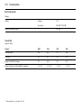
Vehicle specific data
Please enter your vehicle’s data here to keep it ea sily accessible.
This information is available under the section "Technical da ta " as well as on the identification plate and in the Serv ice Booklet.
Fuel
Designati on
Engine oil
Gra de
Viscosity
Tyre pressure
Tyre si ze
wi th full load
S ummer tyres
Front
Rear
Winter tyres
Front
Rear
Weights
Permissible Gross Vehic le Weight
–
EC k erbweight
=
Payload
-1
You r Vivaro
Make use of the Owner’s Manual:
is an intelligent combination of forwardlooking technology, impressive safety,
environm ental friendliness and economy .
z I ts "In brief" section will give you an initial
ov erview.
I t now lies with you to drive your vehicle
safely and ensure that it performs
perfectly. This O wner’s Ma nual p rov id es
y ou with all the necessary informa tion to
that end.
Ma ke sure your passeng ers are aware of
the possible risk of accident a nd injury
which ma y result from improper use of the
v ehicle.
Y ou must a lways comply with the spec ific
law s of the country tha t you are tra velling
through. These la ws may d iffer from the
information in this O wner’s Manual.
When instructed to consult a workshop, w e
recommend that y ou consult y our Va ux ha ll
Authorised Rep airer.
All Vauxhall Authorised Repa irers prov ide
first-c lass service at reasonable prices.
z The table of contents at the b eginning of
the Ow ner’s Manual and within the
individ ual chapters will show you where
everything is.
z I ts index will help you find what y ou
w ant.
z I t will familiarise y ou w ith the
sophisticated technology.
z I t will increase your pleasure in y our
v ehicle.
z I t will help you to hand le y our v ehicle
expertly.
The O wner’s Ma nual is designed to be
clea rly laid-out and easily und erstood.
This symbol signi fies:
6 Continue reading on next page.
3 Items marked with an asterisk are not
fitted to all vehicles (m odel v ariants,
engine options, m odels specific to one
country , optional eq uipm ent, Vauxhall
genuine parts and accessories).
9 Warning
Tex t marked 9 Warning provides
inform ation on risk of accid ent or injury .
Disregard of the instructions may lead to
injuries or endanger life. Inform y our
passengers accordingly.
Yellow arrows in the illustrations serve as
points of reference or indicate some action
to be p erformed.
Bla ck arrows in the illustrations ind icate a
reaction or a second a ction to b e
performed.
Y ou will receive quick, reliable and
individual service.
Directiona l data, e.g. left or right, or front
or back, in the descriptions always rela tes
to the direc tion of travel.
Experienced mecha nics, trained by
Vauxhall, w ork according to specific
Vauxhall instructions.
Thank you for choosing a Vauxhall.
We wish you many hours of pleasurable
driv ing .
The O wner’s Manual should alway s be kep t
in the vehicle: Ready to ha nd in the glove
com partment.
Your Vauxhall Team
0
Contents
Commitment to customer
satisfactio n:
O ur aim: to keep y ou ha ppy w ith y our
vehicle. All Vauxhall Authorised Repairers
offer first class serv ic e at competitive
prices. Ex perienced, fac tory -trained
technicians work ac cord ing to fa ctory
instructions. Your Authorised Repairer can
supply y ou with GENUI NE VAUXHALLAPPROVED PARTS , which have undergone
stringent quality and precision checks, and
of course useful and attractive
VAUXH ALL-APPRO VED ACC ES SOR IES.
O ur name is your guarantee!
For detail s of t he
Vauxhall Authorised Repa irer Network
pl ease ring t his num ber; 0845 090 2044
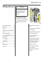
In b rief ... ..... .... ..... .... .... ..... .... ..... .... ..... .... .... . 2
Locks, doors, windows .... .... ..... .... ..... .... .. 17
S eats, interior. ..... .... .... ..... .... ..... .... ..... .... .. 30
Instrum ents, controls.. ..... .... ..... .... ..... .... .. 59
Lighting . ..... .... ..... .... .... ..... .... ..... .... ..... .... .. 76
Infotainment system .. ..... .... ..... .... ..... .... .. 81
C lim ate c ontrol ... .... .... ..... .... ..... .... ..... .... .. 83
Driving and op eration .... .... ..... .... ..... .... . 91
Dropside b od y .... .... .... ..... .... ..... .... ..... .... 121
S elf-help, vehicle care ..... .... ..... .... ..... ... 125
S ervice, maintena nce. ..... .... ..... .... ..... .... 147
Technical data ... .... .... ..... .... ..... .... ..... ... 162
Index.. .... ..... .... ..... .... .... ..... .... ..... .... ..... .... 174
2
In brief
In brief
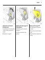
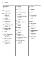
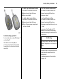
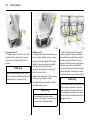
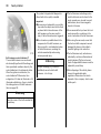
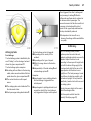
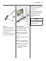
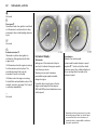
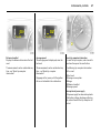
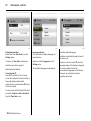
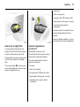
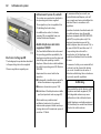
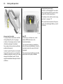
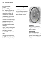
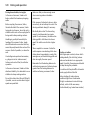
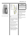
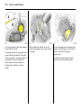
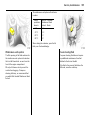
Unlocking the vehicle:
Direct remote control unit 3
towards vehicle, press button c,
pull do or handle
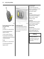
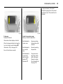
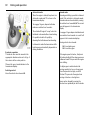
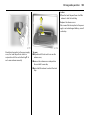
Seat adjustment:
Pull handle, slide seat,
release handle, allow seat to
audibly latch into position
The doors are unlocked.
N ever a djust the driver’s seat while driving.
It could move in an uncontrolled manner
when the handle ha s b een pulled.
To unlock mechanically: insert key and turn
in driver’s door lock, pull door handle.
To lock doors from inside, press central
lock ing sw itch 3 located on the lower part
of the instrument panel.
6 Door locking and unlocking see p age 17,
child safety locks - see pa ge 18,
electronic im mobiliser - see page 18,
ra dio frequency rem ote control 3 see p age 19,
central locking system 3 - see pa ge 21,
mechanical a nti-theft locking system see p age 23,
Vauxhall a la rm system 3 - see page 24.
6 Seat position – see p age 32.
9 Warnin g
Important: Do not sit nearer tha n
10 inches (25 cm) from the steering
wheel, to p ermit safe airbag deployment.
In brief
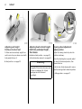
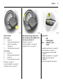
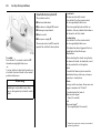
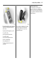
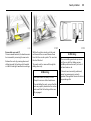
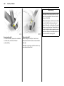
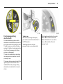
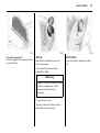
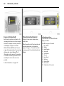
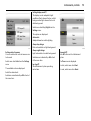
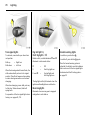
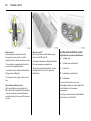
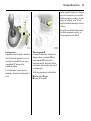
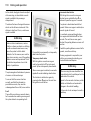
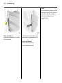
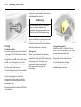
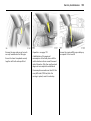
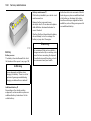
Adjusting the seat backrest:
Pull release lever
Adjusting the lumbar support 3:
Turn handwheel
Move sea t back rest to suit seating position,
it will lock in position when the lever is
released.
Ad just lumbar support to suit p ersonal
requirements.
6 Seat position – see pag e 32.
Do not lean on seat b ackrest whilst
adjusting it.
3
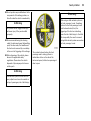
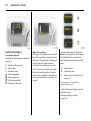
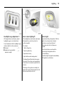
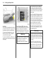
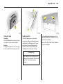
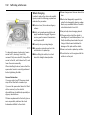
Adjusting armrest support 3:
Adjust armrest sup port to suit personal
requirements.
z Raise armrest in increments to desired
height.
z To reposition, fully ra ise armrest before
low ering.
4
In brief
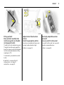
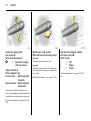
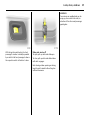
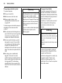
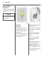
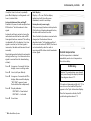
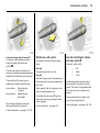
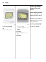
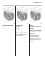
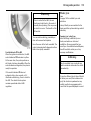
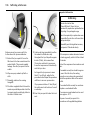
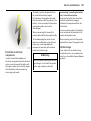
Adjusting seat height:
Pull lever at side of seat
Pull lever and remove body weight from
seat to raise it or press down on seat with
body weight to lower it.
6 Seat position – see pag e 32.
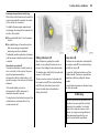
Adjusting head restraint height:
Hold firmly an d adjust h eigh t,
then release
6 Head restraint position – see page 32,
further information, removal – see page 33.
9 Warning
Disregard of these instructions m ay lead
to injuries or endanger life. Vehicle
passengers must be informed
accordingly.
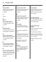
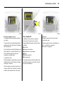
Steerin g wh eel adjustment:
Adjust position
Adjust the steering wheel only when the
vehicle is stationary .
Move the unlocking lever up wards, adjust
the wheel to the desired position, then
release the lev er.
Push the lever firmly d ow nwa rds to ensure
that the steering wheel is lock ed in position.
6 Airb ag systems - see pag e 47.
In brief
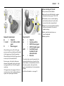
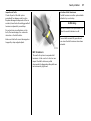
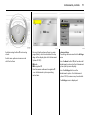
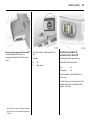
Fitting seat belt:
Draw seat belt smoothly from
inertia reel, guide o ver shoulder
an d engage in buckle
The b elt must not be twisted at any point.
The lap belt must lie snugly against the
body. The backrest must not be tilted bac k
too far (recomm ended max imum tilting
angle approx. 25°).
To release belt, press red button on belt
buckle.
6 Seat belts – see pa ges 36 to 40,
airbag sy stems – see page 47,
seat p osition – see page 32.
5
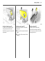
Adjust interior 3 and exterior
mirrors:
Swivel to appropriate position
Electrically adju stable exterior
mirrors 3:
Four-way switch in door panel
Move lever on undersid e of interior mirror
housing to reduce dazz le at night.
Turn switch to left or rig ht: four-way switch
operates corresponding mirror.
6 Mirrors - see page 26.
6 Mirrors - see pag e 26.
6
In brief
In brief
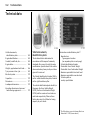
1
Page
Drink holder .. .... ..... .... ..... .... .... ..... .... .. 57
2
Door window defroster v ent.. ..... .... .. 84
3
Side air v ents .... ..... .... ..... .... .... ..... .... .. 84
4
Front pa ssenger’s airbag 3 .. ..... 47, 51
5
Centre air v ents ..... .... ..... .... .... ..... .... .. 83
6
Triple Information Display 3 . ..... .... .. 68
Colour Information Display 3 .... .... .. 70
7
8
7
9
Pa ge
Driv er’s airbag .... ..... .... .... ..... .... ..... .. 47
Horn .... ..... .... ..... .... ..... .... .... ..... .... ..... .. 11
Page
18 S teering w heel m ounted
remote control 3 ..... .... ..... .... ..... .... ... 81
10
Instruments.. ..... .... ..... .... .... ..... .... ..... .. 59
19 C igarette lighter.. ..... .... ..... .... ..... .... ... 58
11
Windscreen wiper
and wash sy stem ..... .... .... ..... .... . 74, 75
Rear d oor a nd tailgate wind ow
wiper a nd wash sy stem 3 ..... .... ..... .. 75
Trip computer 3 ... ..... .... .... ..... .... ..... .. 65
20 C entral locking 3 ..... .... ..... .... ..... .... ... 22
Heated rear w indow s 3 ,
hea ted exterior m irrors 3 . .... ..... .... ... 89
Easy tronic w inter and laden
programm es 3 .... ..... .... ..... .... ..... . 93, 94
Infotainm ent system 3 .. .... .... ..... .... .. 81
Electronic tachograph 3 ... .... ..... .... .. 82
12
Ashtray ... .... ..... .... ..... .... .... ..... .... ..... .. 57
21 Haz ard warning.. ..... .... ..... .... ..... . 23, 78
13
Coin tray
Parking lights, headlight flash,
front fog lig hts, fog tail lig ht,
dipped and main beam ... ... 76, 77, 78
Turn signal lights... .... ..... .... .... ..... .... .. 78
14
Bonnet release . .... ..... .... .... ..... .... ..... 126
15
Starter switch ... .... ..... .... .... ..... .... ..... .... 9
22 Heating and v entilation system .. ... 84
Air conditioning system 3 .... ..... .... ... 87
Rear air conditioning sy stem 3 .... ... 88
16
Head lig ht range adjustment .... ..... .. 79
ESP® P lu s 3
(Electronic S tab ility Prog ra mme) .. 108
Pa rk ing distance sensors 3 ... .... ..... 109
17
Steering wheel adjustm ent ... .... ..... .... 4
23 Utility hook
24 S torage tray
25 Glove compartment
26 Fusebox .. ..... .... .... ..... .... ..... .... ..... .... . 137
8
In brief
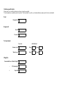
Control indicato rs
Ü Not used
9
Hea dlight dipped b ea m:
see p ages 10, 59, 76.
P
Hea dlight main beam ,
head light fl ash :
see p ages 10, 59, 76.
r
Fog t ail lig ht:
see p ages 10, 59, 78.
>
Front fog lights 3 :
see p ages 10, 59, 78.
u
Anti-lock Brake System (ABS):
see p ages 59, 112.
8
Di esel par ticle filt er 3:
see p ages 60, 106.
F
Not used
v
ESP® Plus (Electronic S tabil ity
Prog ramm e) 3:
see p ages 60, 108.
F
Engine oil l ife m onitor 3 :
see p ages 60, 68, 107.
O
Turn sig na l light s:
see p ages 10, 60, 78.
C
St op engine:
see page 60.
o
Elec tronic im mobil iser:
see pages 18, 60.
A
Serv ice / Engine electronics 3:
see page 60.
D
Prehea ting / Fuel fi lter / Engine
electronics 3 :
see pages 14, 60.
Y
Fuel lev el :
see pages 61, 102, 164, 170.
E
Engine st op:
see page 61.
p
Alt ernat or:
see page 61.
I
Engine oil pressur e:
see page 61.
R
Brak e system:
see pages 61, 111, 156.
v
Airb ag systems, b el t tensi oners:
see pages 37, 47, 61.
H
Front passenger airba g
deact ivat ion 3:
see pages 51, 61.
X
Not used
U
Door open 3:
see page 62.
U
Not used
Z
Exhaust emissions 3:
see pages 62, 104.
B
Not used
Easytronic 3
kg La den program me:
see pages 60, 94.
T
Footb rake ap plica tion:
see pages 60, 91.
W
Transmission el ect ronics:
see pages 60, 96.
A
Automat ic mod e:
see pages 60, 92.
V
Wi nter program me:
see pages 60, 93.
In brief
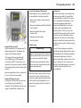
Starter switch:
Diesel engines
St =
I gnition off
A
=
S teering unlocked, ignition off
M =
I gnition on: preheating
(see page 14)
D
=
S tart (tra nsmission in neutral)
Petrol engines
St =
Ignition off
A
=
Steering unlock ed, ignition off
M =
Ignition on
D
=
Start (transm ission in neutra l)
6 Starting - see page 14,
electronic immobiliser - see pa ge 18,
parking the vehicle - see pag e 16.
Releasing steering column loc k:
Mo ve steering wheel slightly and
turn key to position ‘A’
6 Starting - see p age 14,
electronic im mobiliser - see page 18,
parking the v ehicle - see page 16.
9
Light switch:
7
= Off
0
= Parking lights
9 P = Dipped or main
beam
6 Head lig ht warning device - see pag e 74,
further inform ation - see p age 76,
automatic d ip ped beam activation 3 see page 77,
hea dlight ra ng e adjustment - see pag e 79,
hea dlights when driving abroad see page 80,
day time running lights 3 - see page 76.
10
In brief
Fog lights:
7
= Off
>
= On
(front fog lights 3
only)
>r = On
(front fog lights 3
and fog tail light)
6 Fog tail light, front fog lights see page 78.
Headlight flash, main beam and
dipped beam:
Pull stalk towards steering wheel
6 Further information - see pag e 77.
Turn sign al lights:
Stalk in rest position
Upwards
= Right turn
Do wn wards = Left turn
6 For operation of the turn signal lights
when tow ing - see pages 60, 118,
turn signal lig hts - see pag e 78.
In brief
Hazard warning lights:
On
=
Press button ¨
Off =
Press button ¨ again
6 Further inform ation - see pages 23, 78.
Horn:
Press any pa rt of the steering wheel c entre
to activate the horn.
6 Airbag system s – see page 47,
steering wheel m ounted remote control 3 see p age 81.
11
Win dscreen wiper:
Move stalk downwards
K
=
Timed interval wipe
1
=
Slow
2
=
Fast
Return the stalk to its original p osition to
turn off.
6 Further inform ation - see pages 74, 157,
143.
12
In brief
Automatic wiping with
rain sensor 3:
Move stalk downwards
K
=
Autom atic wiping
with rain sensor
Adjust sen sitivity:
Rotate adjuster ring
Less sensitive = Rotate adjuster
forwards
More sensitive = Rotate adjuster
backwards
The rain sensor detects the am ount of
water on the windscreen a nd automatically
reg ulates the windscreen wiper frequency.
6 Further information - see p ages 75, 143 ,
158.
Windscreen wash system:
Pull stalk towards steering wheel
Short pull
The wiper operates for one cycle.
Long p ull
Wash fluid is spray ed onto the windscreen,
at the same time the wip er is operated for
four cy cles.
6 Further information - see pag es 75, 159.
Rear door and tailgate window
wash wipe system 3:
Rotate switch
0
=
Off
e
=
Wiper
f
=
Wash
6 Further inform ation - see pag es 75, 158,
159.
In brief
13
Before starting-off, check:
z Tyre pressures and condition.
z Engine oil level a nd fluid levels in engine
compartment (see pa ges 150 to 153).
z All windows, mirrors, exterior lig hting
and number plates are free from dirt,
snow and ice a nd are operationa l.
z Objects are securely located and will not
be thrown forwards in the event of
sudden braking.
z Seats, seat belts and mirrors are
correctly a djusted .
Manual transmission:
o
=
Neutral
1 to 5/6 =
1st to 5th or 6th
gear
R
=
Reverse gear
3
When shifting up from 4th to 5th gear,
pressure must be exerted towards the right
at the beg inning of the shift operation.
When shifting from 5th to 4th gea r, do not
exert a ny forc e towards the left.
Reverse gear: with vehicle sta tionary,
depress clutch p edal, pull up collar and
move gearshift lev er to the left aga inst
resista nce.
If the gear does not engage: w ith lever in
neutral, release clutc h pedal and depress
again, then repeat gear selection.
Easytronic 3:
N
=
Neutral
o
=
Centre position
=
Shift to lower gear
+
=
Shift to high er gear
A/M
=
Switch between
Automatic and
Manual m ode
R
=
Reverse
The selector lever must be moved in the
appropriate d irection as far as it will go.
Upon relea se, it automatically returns to
the centre position. Pay heed to the
gear / mode indicator in the tra nsmission
display .
6 Further information - see pag e 91.
z Brake operation.
14
In brief
Exhaust gases are poisonou s
Ex haust ga ses c ontain carbon m onoxid e,
which is ex tremely poisonous but has no
odour or colour.
Therefore, never inha le exhaust gases, and
nev er run the engine in an enclosed space.
You should also a void driving with the
doors op en, as exhaust gases could enter
the p assenger compartment.
6 Exhaust gases - see page 107.
Starting, petrol engines:
Transmission in neutral,
depress clutch pedal 3,
do not accelerate,
turn key to position D
The inc reased engine speed automatically
returns to normal idling speed as the
engine temperature rises.
6 Electronic immobiliser - see pa ge 18,
further inform ation - see pages 97, 99, 101.
Starting, diesel engines:
Tran smission in neutral,
depress c lutch pedal 3,
do no t accelerate,
turn key to position M,
wait until preheating control
indicator D extin guishes 1) ,
turn key to position D
6 Electronic im mobiliser - see page 18,
eng ine preheating 3 - see page 60,
diesel fuel system 3 - see pa ge 125,
further information - see pag es 97, 99, 101.
1)
Preh eatin g system sw itches on o nly if outside
tem perature is low .
In brief
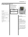
Drying misted-up or iced-up
windows:
Set temperature rotary knob
to red,
set fan to position 4,
set air distribution to V
Close centre air vents; open side air v ents
and direct them towards the door windows.
6 Heating and ventilation sy stem see page 84,
air conditioning sy stem 3 - see page 87.
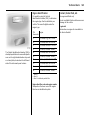
Heated rear windows 3,
heated exterio r mirrors 3
Press Ü
= On
Press Ü again
= Off
6 Further information - see pag e 89.
To release th e handbrake:
Raise lever slightly,
press release button,
lower lever fully
6 Handbrake - see page 112.
15
16
In brief
Parking the vehicle:
Advice when parkin g:
z Ap ply handbrak e firm ly without p ressing
the release button, and a pply as firmly
as possible on slopes.
z Do not park vehicle on easily ignitable
surfaces as the hot exhaust system
temperatures could cause the surface to
ignite.
z Switch engine off by turning ignition k ey
to position "St ". Rem ov e ignition key and
turn steering wheel until lock is felt to
engage (anti-theft protection).
z If the vehicle is park ed on a fla t surface
or an up hill incline, with manual
transmission enga ge first gea r or with
Easytronic 3 mov e the selector lever to
the centre position before switching off
the ignition. On an uphill incline, also
turn the front wheels away from the kerb.
z If the vehicle is park ed on a downhill
incline, with manual transmission or
Easytronic 3 engage reverse gear before
switching off the ignition. Also turn the
front wheels towards the kerb.
z Lock doors and load compartment with
key in lock or button e or G on remote
control 3.
z To arm the Vauxhall alarm sy stem 3 ,
press button e once, a nd to a ctiv ate the
mechanical anti-theft locking system ,
press b utton e tw ic e.
z C lose windows.
z The engine cooling fans may run a fter
the engine has been switched off –
see page 97.
6 Further informa tion - see p ages 18, 97,
ra dio frequency rem ote control 3 see p age 19,
central locking system 3 - see pa ge 21,
Vauxhall a la rm system 3 - see page 24.
That was a brief overview of the
most important in formation for
your first drive in your Vivaro.
Your vehicle has still more
instrum ents and con trols,
possibly also o ptional
equ ipment.
The remain ing ch apters of the
Owner’s Manual contain
impo rtant information on
operatio n, safety and
maintenance as well as a
com plete index.
Loc ks, do ors, windo ws
Locks, doors, windows
Replacement keys
Lock cylinders
The key is a c onstituent of the electronic
immobiliser. Ordering keys from a Vauxhall
Authorised Repairer g uarantees problem free op eration of the electronic
immobiliser. Keep spare key accessible in a
safe place.
Designed to free-wheel if they are
forcefully rotated without the correct key or
if the correct key is not fully inserted.
Locks - see pa ge 146.
Door locking and unlockin g
From outside:
Pull outsid e handle to open the front door.
Replacem ent keys ... ..... .... ..... .... .... .....
Door locking and unlocking.. .... .... .....
Loc k cylinders . ..... .... ..... .... ..... .... .... .....
Ca r Pass 3 ... .... ..... .... ..... .... ..... .... .... .....
Child safety lock .. .... ..... .... ..... .... .... .....
Electronic immobiliser... .... ..... .... .... .....
Radio frequency remote control 3 ....
Central locking system 3 . ..... .... .... .....
Mechanica l anti-theft loc king sy stem
Vauxhall alarm system 3. ..... .... .... .....
Sliding side doors 3. ..... .... ..... .... .... .....
Rear doors 3 ... ..... .... ..... .... ..... .... .... .....
Tailgate 3 ... .... ..... .... ..... .... ..... .... .... .....
Mirrors. ..... .... .... ..... .... ..... .... ..... .... .... .....
Wind ow s.. .... .... ..... .... ..... .... ..... .... .... .....
Sunvisors.. .... .... ..... .... ..... .... ..... .... .... .....
17
17
17
17
18
18
19
21
23
24
25
25
26
26
28
29
17
Radio frequency rem ote control 3 see p age 19,
central locking system 3 - see pa ge 21,
mechanical a nti-theft locking system see p age 23.
From inside:
Pull the inside lev er to open the front door.
The door can be locked or unlocked by
pushing / pulling t he interior lock button 3
or using the central locking switch 3 see p age 22.
To prevent the driver from being
inad vertently locked out, the front doors
cannot b e locked when they are open.
The tailgate can be opened by pushing
down the tailgate interior release 3 .
To reset, turn cylinder with the correct k ey
until its slot is v ertical, rem ov e key a nd then
re-insert it. If the c ylind er still free-w heels,
turn the key through 180° and repeat
operation.
Car Pass 3
The Car Pass contains all of the vehicle’s
data and should therefore not be kept in
the vehicle.
Hav e y our Car Pass to ha nd when
consulting a Vauxhall Authorised Repairer.
18
Lo cks, doors, windows
Child safety lo ck
Electronic immobiliser
The c hild safety lock for the sliding side
door 3 is located on its rearward fa cing
edge.
The system check s whether the v ehicle may
be started using the key that has been
inserted. If the key is rec og nised as
"authorised" the v ehicle can be started.
The check is carried out v ia a transpond er
housed in the key.
9 Warning
Use the child safety lock w henever
children are oc cup ying the rear seats 3.
Disreg ard may lead to injuries or
endanger life. Vehicle passengers must
be informed accordingly.
To enga ge, turn knob from the vertical
position: anticlockw ise for right-hand side
door or clockwise for left-ha nd side door.
Door cannot then be opened from inside.
The electronic imm ob iliser is automatically
activated when the key is remov ed from
the starter switch.
The electronic imm ob iliser is automatically
activated when the key is remov ed from
the starter switch and also if the k ey is left
in the starter switch when the engine is
turned off. Reinsert the key to start the
engine.
C ont rol indic ator for im mobi liser
The control indicator illuminates when the
ignition is switched on then ex ting uishes.
If the control indicator flashes rapidly after
the ignition is switched on, there is a fault in
the immobiliser system.
z Turn ignition off and remov e k ey,
z wait approx. 2 seconds,
z then repeat starting procedure.
If the control indicator fails to extinguish,
try to start the engine using the spare k ey.
O btain assistance from a workshop.
Not e
The immobiliser does not lock the doors.
Therefore, after leaving the vehicle, always
lock it and switch on the Vaux hall alarm
system 3.
Loc ks, do ors, windo ws
C entra l lock ing system 3
see page 21.
Mechanic al anti -theft locki ng system
see page 23.
Vauxhall ala rm system 3
see page 24.
Radio frequen cy remote c ontrol 3
The remote control is used to operate the
central lock ing sy stem 3.
For your conv enience, we recommend that
the central lock ing sy stem is alway s
op erated using the remote control unit.
Dep ending on model, the vehicle may use
a remote control with two or three b uttons
(selectiv e door locking).
Treat the remote control unit with care; it
should be protected against moisture and
should not be operated unnecessarily .
The remote control has a range of approx.
5 metres. This ra nge can b e affected b y
outside influences. Aim the rem ote control
at the vehicle to opera te.
19
20
Lo cks, doors, windows
Note
If the central locking system 3 cannot be
opera ted with the remote c ontrol, this may
be due to the follow ing reasons:
z The rem ote control is out of range.
z The battery voltage of the remote
control is too low. Change the battery in
the rem ote control unit.
z The rem ote control ha s b een op erated
too many times in succession outside the
vehicle’ s reception range (e. g. at too
great a distance from the vehicle).
The rem ote control must b e
reprogrammed, we recommend you
consult a workshop .
z Interference from higher p ow er radio
waves from other sources.
Loc k or unloc k the d oors manually using
the k ey or central locking switch 3.
Manual locking does not operate the
central locking sy stem. Hav e cause of fault
rem edied by a workshop.
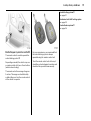
Changing the battery in remote control
uni t
Replace the battery in a ccord ance with the
Serv ic e Booklet or when the range of the
remote control starts to become reduced.
Tw o function remot e cont rol unit:
Open the ba ttery com partment by
inserting a coin into the slot and twisting.
Ensure the new battery is installed
correctly.
Replace the cover a nd press until it is fully
engaged.
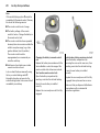
Selecti ve door lock ing rem ote cont rol unit :
O pen the battery compartment by
removing the sc rew on the rear cover, then
inserting a coin into the slot and twisting .
Ensure the new battery is installed
correc tly .
Replace the cover and press until it is fully
eng aged, then replace and secure screw.
Mak e sure that you dispose of old batteries
in accordance with env ironmental
protec tion regulations.
Loc ks, do ors, windo ws
Cen tral locking system 3
For front, side and rear doors 3, tailgate 3
and tank flap 3.
With selective door locking 3 , the
passenger com partment a nd rear load
compartment are loc ked and unlock ed
separately.
21
To unl oc k - t wo function remot e c ont rol:
Press button c on remote control unit:
To lock - tw o func tion remote control :
Press button e on remote control unit:
z Haz ard warning lights flash once.
z Doors are unlocked .
z Hazard warning lig hts flash twice.
z Doors are locked .
To unl oc k - selectiv e d oor locki ng :
Press button c on remote control unit:
To lock - sel ec tive door l ocking:
Press button e on remote control unit:
z Haz ard warning lights flash once.
z Doors of the passenger c om partment
only are unlock ed.
z Hazard warning lig hts flash twice.
z Passenger compartment doors only are
loc ked.
Alway s ensure tha t the side door 3 ,
tailgate 3 or rear doors 3 are properly
closed before lock ing the vehicle w ith the
remote control.
9 Warnin g
For safety reasons, the vehicle cannot be
loc ked if the ignition key is in the starter
switch.
Manually lock ing or unlocking a door with
the key does not opera te the central
locking system .
For manual operation of the tank flap see page 103.
22
Lo cks, doors, windows
Autom atic locking 3
The central locking system can be
activa ted to a utomatica lly lock the doors
as soon as a sp eed of approx.
4 mph (6 km /h) is reached.
To act ivat e
With the ignition switched on, press e on
the central locking switch and hold for
app rox . 5 seconds, until audible
confirmation is heard.
Rear load compa rtment doors / tailg ate sel ec tive door l ocking
To unlock :
Press button G on remote control unit.
The rear load com partment doors /
tailgate are unlocked.
If no door is opened within approx.
30 second s after the v ehicle has been
unlock ed via the remote control, the vehicle
is relocked automatically.
To lock :
Press button G on remote control unit.
The rear load com partment doors /
tailgate are lock ed.
Central l oc king sw itch 3
Use the c entral locking switch to lock or
unlock the doors from inside the vehicle.
Press e on the switch to lock or U on the
switch to unlock.
To deact ivat e
With the ignition switched on, press U on
the central locking switch and hold for
app rox . 5 seconds, until audible
confirmation is heard.
Unlock ing the door
The doors are unlock ed by opening any
door from insid e the vehicle or by
operating the central loc king sw itch.
9 Warnin g
If a rear door is opened , it will
autom atically be relock ed w hen the
vehicle reac hes a speed of approx .
4 mph (6 km/h).
Loc ks, do ors, windo ws
Fault
In the event of a fault, e.g. automa tic
locking doesn’t ta ke p lace, ensure all the
doors hav e been properly closed . Check to
ensure that the automatic locking function
has not been dea ctiv ated inad vertently . If
this is the case, switch the ignition off and
on again and reactivate the system as
described previously.
Slam door lock s 3
For certain Van m odels 1) the slid ing side
door and rear door lock s are isolated for
added security.
Whilst the front doors are locked and
unlocked using the rem ote control key in
the normal way , the sliding side door and
rear d oor can only be op ened by m anual
op eration of the vehicle k ey.
If the automatic loc king function still fails to
opera te, we rec om mend that y ou seek the
assistance of a workshop.
9 Warning
23
Mechanical anti-theft locking
system
To lock :
All doors must be closed; press button e on
the remote control unit 3 again within
10 seconds after locking. H azard wa rning
lights fla sh 5 times.
-orTurn k ey in driver's door lock towards front
of vehicle ag ain within 10 seconds after
locking, then turn it back to the vertica l
position a nd remove.
Interior lock buttons 3 on all doors are
positioned suc h that doors cannot be
opened.
If y ou decide on hav ing the system active
(with the doors c losed ) while driving, it
may b ecome difficult for those a ssisting
you in gaining access to your vehicle in
the ev ent of an emergency.
9 Warnin g
Do not use the system if there are people
in the vehicle! The doors cannot b e
unlocked from inside.
I mporta nt:
When the ha zard warning lights or parking
lights are on, the mechanical anti-theft
locking system will not be activated.
1)
N ot availab le w ith m echa nica l anti-theft
locking system.
24
Lo cks, doors, windows
Vauxhall alarm system 3
The system m onitors:
z Front a nd side doors.
z Rear doors or ta ilg ate 3 , bonnet.
z Passenger comp artment.
z Starter switc h.
z Siren power supply 3.
The rem ote control unit 3 is used to
op erate the anti-theft alarm sy stem.
To unlock:
Press button c on remote control unit 3.
Haza rd warning lights flash once.
-orTurn key in driver's door lock towa rd s rear
of vehic le, then turn it b ack to the vertical
position and remove.
9 Warning
Unlocking is not possible in any other
way, so keep spare key to hand in a safe
place!
To act ivat e
All doors must be fully closed :
Press button e on the remote control;
the turn signal lights flash twice.
If the turn signal lights do not flash on
activa tion, this ma y ind icate that a door or
the bonnet is not fully closed .
To deact ivat e
Press button c on the remote control;
the turn signal lights flash once.
If the alarm has been triggered, the turn
signal lights w ill not flash upon
deactivation.
When unlocking the v ehicle using the key ,
the alarm will sound : to deactivate, insert
the key and switch on the ignition.
Not e
The anti-theft alarm system c annot be
deactivated in any other way, so k eep a
spare key in a safe place.
Ala rm
During a switch-on p ha se, the sensors can
trigger a ma ximum of 10 times 1) .
The alarm takes the form of:
z an acoustic signal
(horn, 25 seconds)
and
z a visual sig nal 1 )
(turn signal lights, 25 seconds).
1)
Varies from coun try to coun try on a ccount of
nationa l regu la tion s.
Loc ks, do ors, windo ws
25
Passenger com part ment monitori ng
When the anti-theft alarm is activ ated, the
system a utomatica lly monitors the inside
of the v ehicle for m ovem ent.
To disable the passenger compartment
monitoring, (for exam ple if an a nim al is to
be left in the vehicle):
z Press and hold b utton e on the remote
control.
z An a udib le beep will sound to confirm
that the passenger c om partment
monitoring func tion is disabled .
The disa ble monitoring function will remain
until the alarm is d eactivated or the doors
unlock ed.
Sliding side doors 3
Rear doors 3
Alar m bac k-up syst em 3
The a la rm system has a battery back-up
siren unit whic h, in the event of its power
sup ply being disconnected or
disconnection of the vehicle battery, w ill
sound for approx. 5 m inutes on its interna l
batteries.
Open the door by pulling the outsid e
ha ndle, or by pulling the interior lever to
the rea r, then sliding the door ba ckwards.
The doors can b e locked or unlocked with
the remote control 3 , the central locking
switch 3, or the key 3 .
To close the door, slid e it fully forwards and
ensure it is fully closed.
To open the left-hand rear door, pull the
outside handle. The door is opened from
insid e the vehicle by pulling the interior
handle.
If the vehicle battery has to be
disconnected it will be necessary to
deactivate the alarm sy stem.
To stop the siren if activated, reconnect the
vehic le ba ttery and press button c on
rem ote control unit.
The door can be locked or unlocked with
the rem ote control 3, the central lock ing
switch 3 or by the interior lock switch.
Ensure the side door is closed before
driving the v ehicle.
The rig ht-hand rear door is released using
the lever (arrowed).
9 Warnin g
The rea r lights m ay be obscured if the
rear doors are open and the vehic le is
parked on the roadside. You should
make other road users aware of your
vehicle, by using a warning tria ngle or
other eq uipm ent specified by your
country’ s road tra ffic regulations.
26
Lo cks, doors, windows
The d oors are retained in the 90º position
by locking sta ys.
To op en the doors to 180º or further 3, pull
the d oor release hand les and swing open
to the d esired p osition.
9 Warning
Ensure ex tended opening doors 3 are
secured when fully opened.
Opened d oors may sla m closed d ue to
the force of the wind!
Always close the right-hand door before
the left-ha nd door.
Tailgate 3
Mirrors
To op en: press button and lift tailgate to
fully op en position.
I nt eri or 3 and exterior mi rrors
To adjust mirrors, swiv el to ap prop riate
position.
In very cold clima tes, the op ening
assista nce provided by the tailga te
hy draulic struts may be reduced.
The tailgate can be locked or unlock ed
with the rem ote control 3 or the central
lock ing sw itch 3.
9 Warning
Ensure there is adeq ua te clearance both
above (at least 2.15 m ) and behind when
opening tailga te.
Close tailgate using the interior strap .
Ensure tailgate is fully closed.
Move lever on underside of interior mirror
housing to reduce d azzle at night.
Take care when driving with interior mirror
adjusted for night vision. Rear v iew may be
slightly distorted in this position.
Loc ks, do ors, windo ws
27
Aspherica l exterior m irror
The aspherically curved mirror glass
increa ses the field of v iew. Estimating the
distance a way from v ehicles follow ing you
is only p ossible to a limited extent because
of slight distortion.
Elec trical ly ad justable ext er ior mirror s 3 :
Adjust m irrors using switch located in
driver’s door.
O perational with the ig nition on or off.
Turn switch to left:
Sw itch operates left-hand m irror.
Turn switch to right:
Sw itch operates right-hand mirror.
Switch in c entral position:
Mirror adjustm ent is off.
The lower aspherical m irrors are not
adjusta ble.
For the safety of pedestrians, the exterior
mirrors will swing out of their normal
mounting position in the ev ent of an
accident-like impact.
28
Lo cks, doors, windows
Windows
9 Warning
Care must b e tak en when op erating the
elec trically operated windows. There is a
risk of injury , pa rticularly for children, and
a danger tha t articles could become
trap ped. Vehicle p assengers m ust be
informed accordingly.
Make sure tha t all vehic le occupants
know how to operate the w indows
correctly.
Keep a close wa tch on the w indows when
closing them . Ensure that nothing
becomes trapped in them a s they move.
Before leaving the vehicle, remove the
ig nition key in order to prev ent
unauthoriz ed operation; risk of injury.
Door window s
The door windows can be opera ted with
the crank.
Electrica lly op era ted door w indows 3
With the ignition switched on, operate the
driver’s wind ow using the switch located in
the driver’s door.
To open the window, push the top of the
switch and to close, pull the top of the
switch. The wind ow stops when the switch
is released.
Autom atic oper ation 3
With the ignition switched on, briefly push
or pull the switch to fully open or close the
driver’s window. Briefly push or pull the
switch aga in to stop the window during this
operation.
Loc ks, do ors, windo ws
Su nvisors
The sunvisors are padded and can be
swung up, d own a nd to the side, for
protec tion of the driver and passenger
aga inst glare.
With the ignition switched on, the front
passenger’s window is similarly operated
by a switch in the front passeng er’s door or
the resp ective switch in the driver’s door.
Slidi ng side window s 3
To op en, pull up catch and slide open.
To close, pull up catch and slide window
until catch engages.
Note: during wind ow opening or closing ,
keep the catch raised to allow the glass
sufficient clearanc e.
29
30
Seats, interior
Seats, interior
Front sea ts .. .... ..... .... ..... .... ..... .... .... .....
Head restraints .... .... ..... .... ..... .... .... .....
Rear seats 3 .... ..... .... ..... .... ..... .... .... .....
Three-stage restraint sy stem .... .... .....
Three-point seat belts .. .... ..... .... .... .....
Belt tensioners. ..... .... ..... .... ..... .... .... .....
Using the belts ..... .... ..... .... ..... .... .... .....
Child restraint systems 3 . ..... .... .... .....
Airbag system s .... .... ..... .... ..... .... .... .....
Front passenger airbag deactivation 3
Loa d compartment net 3 ..... .... .... .....
Loa d compartment cover 3 . .... .... .....
Ashtray .... .... .... ..... .... ..... .... ..... .... .... .....
Drink holders ... ..... .... ..... .... ..... .... .... .....
Warning triangle ¨ 3, First-aid kit + 3
Power outlets .. ..... .... ..... .... ..... .... .... .....
30
32
33
36
36
37
39
41
47
51
54
54
57
57
58
58
Front seats
9 Warning
Never adjust seats w hile driving, as they
could mov e uncontrollably .
Imp ortant: Do not sit nea rer than
10 inches (25 cm) from the steering
wheel, to perm it safe airba g deploy ment.
Adjust seat longi tudinally 3:
To adjust, p ull the handle on the front seat,
slide the seat and release the handle.
Ad just ing front seat b ackrests
To adjust, pull release lever, move seat
bac krest to suit seating position and loc k in
position w hen the lever is released .
Do not lea n on seat back rest whilst
adjusting it.
Seats, interior
Adj usti ng the lumba r sup port 3
To adjust, turn the handwheel whilst
relieving the load on the bac krest.
Adjusting a rmrest support 3:
Ad just armrest support to suit personal
requirements.
Adjust lumb ar support to suit personal
req uirements.
z Raise armrest in increments to d esired
height.
z To rep osition, fully raise arm rest before
lowering.
31
Ad just ing sea t height 3
To adjust, pull lever a t side of seat.
Pull lev er and remove body weight from
seat to ra ise it or press down on seat w ith
body weig ht to lower it.
32
Seats, interior
Seat p osi tion
Adjust d riv er’s seat such that with the
driver sitting upright the steering wheel is
held in the area of its upper sp ok es w ith the
driver’s arms slightly bent.
The seat backrests must not be tilted too
far back (recomm ended max im um tilting
angle approx. 25°).
9 Warning
Disreg ard can lead to injuries which could
be fatal. Vehicle pa ssengers m ust be
informed accordingly.
Head restraints
Ad justing head restra int height, hold firmly
and adjust height, then release.
Do not a tta ch objects or components that
are not app rov ed for the Viva ro, to the
head restraints. These affect the protective
effect of the head restra ints and ca n be
prop elled through the vehicle in an
uncontrolled m anner if the driv er brak es
ha rd or an accident occurs.
Head restra int position
The centre of the head restraint should be
at eye lev el.
Adjust to hig hest position if this is not
possible for ex tremely tall p eople, and
adjust to lowest position for extrem ely
small people.
9 Warnin g
Disregard ca n lead to injuries which c ould
be fa ta l. Vehicle passengers must b e
informed accordingly.
Seats, interior
Head restrai nt remova l
To remove the head restraints, pull lock tab
and pull the restraint up wards.
Stow head restraints securely in load
compartment. Do not drive with head
restraints removed if the seat is occupied.
Rear seats 3
On some model variants, the rea r
passenger compa rtm ent offers storage in
the seat trims.
To enable long items to be stored under
the seats, the centre rear seat trim cov er 3
can be unclipp ed.
The load cap acity can be increased further
by folding or removing the rear seats 3.
33
When folding or rem oving the rear seat
ensure the armrests 3 a re folded away in
their m ost upright position. Also remove
the low er seat trim side pock ets 3
disconnecting them from the locating clips.
34
Seats, interior
Rear seat ac cess 3
To facilitate access to the rear seats, fold
the seat backrest forwards. If necessary
release the two-latch seat belt from its
buckles.
9 Warning
Ensure that the ba ckrest returns to its
correct position a nd the seat belt buc kles
engage securely - see page 39, 40.
Fold ing sea ts 3
On some m od el variants, the load area can
be increased by folding up the rear seats.
Remove the head restraints. Pull the side
ha ndle to release the backrest and fold
forwards onto the seat cushion, if
necessary releasing the two-latch sea t
belts from their buckles.
Release both locking bars at the rear base
of the seat b y pulling back wards.
Lift and fold the seat assembly , until the
seat frame rests in place.
9 Warning
When folding the seat use caution beware of moving parts. Ensure the seat
is secure when completely folded.
To return the folding seat to the upright
position, support the seat assembly and
release the bar by pulling the ba r directly
towards you. Gra dua lly lower the seat
assembly , allow ing the rear support legs to
fold down. Lower the sea t completely,
ensuring the rear sup port legs are located ,
and la tc hed. R aise the b ackrest, reinstall
hea d restraints and connect the seat b elts.
9 Warnin g
When installing the seat, ensure that the
seat is properly located on the anchor
points and that the locking catches a re
fully engaged , the b ackrest is returned to
the c orrect position and the sea t belts are
engaged securely.
Seats, interior
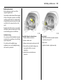
Remov able rear seats 3
O n som e model variants, the load area can
be increased by removing the rear sea ts.
Release the seats by pressing d ow n and
slid ing forwa rd the locking c atch located
on the left and right-hand sea t m ountings.
With both catches ra ised, push the seat
unit towards the rear and relea se them
from the floor anchor p oints. The seat can
then be lifted out.
The seats must be removed through the
sliding door only.
9 Warning
Removable seats are heavy ! Do not
attempt to rem ove without assistance.
When installing the sea ts, ensure tha t the
seats are p roperly located on the anchor
points and that the locking catches are
fully eng aged.
35
9 Warnin g
When re-installing sea ts a lw ays ensure
tha t the row with the folding access
seat B is positioned correctly in front of
the fixed seat row A.
If the sea ts are incorrectly positioned,
access for passengers is seriously
imped ed. Disregard of these instructions
may endanger life.
36
Seats, interior
Three-stage restraint system
The system comprises
z Three-point seat belts.
z Belt tensioners on the front seats.
z Airbag sy stems for driver, front
passenger 3 and outb oa rd rear seat
occ upa nts 3 .
The three stages are activated in sequence
depending on the seriousness of the
accident:
z The automatic seat belt locking d evices
prevent the belt strap from b eing pulled
out and thus ensure that the vehicle
occ upa nts are retained in their seats.
z The front seat belt buckles are pulled
downw ards. As a result, the seat belts
are instantaneously tightened and the
occ upa nts are made awa re of the
deceleration of the vehicle at a very early
stage. This reduces stress placed on the
body.
z The airbag system is additionally
trigg ered in the event of a serious
accident involving a frontal im pact and
forms a sa fety cushion for the driver and
front passenger 3. The side airbag
system 3 p rotects the occupants in the
front of the vehicle in the event of side-on
collisions.
9 Warning
The airb ag system serves to supplement
the three-point seat b elts and belt
tensioners. The seat b elts must therefore
alway s be worn. Disregard of these notes
can lead to injuries which may be fa tal.
Vehicle passeng ers must be informed
accordingly.
Be sure to read the detailed descriptions
of all the restraint system s on the
following pages!
Three-point seat belts
The vehicle is equipped with three-point
seat belts with automatic retrac tors and
locking d evices, allowing freedom of body
mov ement although the spring tensioned
belts are alwa ys a snug fit.
The belt has a “vehicle sensitive retractor”
which is designed to lock during hea vy
acc eleration or deceleration in any
direction.
9 Warnin g
Alw ays wear your seat belt - and that
mea ns also in urban traffic and when you
are a rear seat passenger. It can save
your life!
Pregnant women too must always wear a
seat belt.
In the ev ent of an accident, people not
wearing seat belts endanger their fellow
occupants and them selves.
S eat belts are designed to b e used by only
one person at a time. They are only
suita ble for children a ged up to 12 or
smaller than 150 cm if used in conjunction
with a child restra int.
Seats, interior
Inspecti on of bel ts
Check all parts of the belt system
periodica lly for damag e and function.
Replace damaged comp onents. After an
accident, have the b elts and triggered belt
tensioners replaced by a workshop.
37
Act uation of belt tensioners
The b elt tensioners must be repla ced a fter
activa tion b y a w ork shop.
9 Warnin g
The belt tensioners a re operational only
when the control indicator is unlit.
Do not perform a ny alterations on the
belts, their anchora ges, the autom atic
retractors or the b elt buckles.
The seat belts remain fully opera tional
even w hen the belt tensioners ha ve been
actuated.
Make sure that belts are not dam aged or
trapped by sharp-edged objects.
Belt tensioners
The seat b elt systems incorporate b elt
tensioners. I n the event of a front or rea r
impact the belt b uck les are pulled
downwards; the diagonal and la p belts are
instantaneously tightened.
38
Seats, interior
The system’s integ ra ted self-diagnostics
allow s faults to be quickly remedied.
Imp or tant
z Accessories not released for your v ehicle
type and other ob jects m ust not be fix ed
or placed within the a ction z one of the
belt tensioners a s they ma y result in
injury if the belt tensioners are triggered.
Belt tensioner s c ont rol indic ator v
The seat belt tensioners are monitored
electronic ally together with the airbag, and
their operational readiness shown by the
control indica tor in the instrument cluster.
When the ig nition is sw itched on, the
control indica tor v illuminates, then
exting uishes. If it does not illuminate or if it
illuminates while d riv ing , there is a fault in
the a irb ag system or the belt tensioners
(also see p age 50).
9 Warning
Have the cause of the fault remedied by
a workshop.
z Do not mak e any modifications to the
components of the belt tensioners, as
this may result in unintended actuation
of the b elt tensioners, rendering the
vehicle unroadworthy and ca using
serious personal injury.
9 Warning
Imp roper handling (e. g. removal or
installation) can activ ate the belt
tensioners – risk of injury .
z The belt tensioner and airbag sy stem
control electronics can be found in the
centre console area. In order to av oid
malfunctions, do not store mag netic
objects in this a rea.
z We recom mend that you have the front
seats removed by a w orkshop in the
event of actuation of the belt tensioners.
z When using the rear sea ts, ensure that
the front seat belt components are not
damaged by shoes or other objects.
Avoid dirt getting in the retractors.
z The belt tensioners only actuate once,
ind ic ated b y continuous illum ina tion of
control indicator v in the instrum ent
cluster. Deploy ed belt tensioners must be
replaced by a workshop.
z When disp osing of the v ehicle, plea se
observe the applica ble safety
regulations. Please have the vehicle
disposed of by a company whic h reuses
vehicle parts.
Seats, interior
Using the belts
Fitting the b el t
Pull the belt out evenly from the retractor
and guide it across the body, mak ing
certa in that it is not twisted.
Insert the la tch plate into the buckle. The
seat b ackrest must not be tilted bac k too
far; the recommended angle of inclination
is approx. 25°. The lap belt m ust not be
twisted a nd must fit snugly across the
body. Tension the belt frequently while
driving by tugging the diagonal pa rt of the
belt.
9 Warning
O n pregnant w om en in p articular the lap
belt must be positioned a s low as
possible across the pelv is in order to
prevent pressure on the abdomen.
Bulk y clothing prevents the belt from fitting
prop erly. The belt must not rest against
ha rd or fragile objects in the pockets of
your clothing (e.g. ballpoint pens, keys,
spectacles) because these could cause
injury. Do not place any objec ts (e.g.
ha ndb ags) between the belt a nd your
body.
39
Upp er anchorage point
height a djustment 3
z Do not adjust heig ht while driving,
z slide adjuster up or down to d esired
position.
Adjust height such that the belt passes
over the w earer’ s should er and rests
aga inst the shoulder. It must not pass over
the neck or upp er arm.
40
Seats, interior
9 Warnin g
The seat b elt will not be effective in the
event of an accident if the lower latch is
not c orrectly fitted.
When releasing the seat belt, ensure that
the central buckle is alwa ys released
before the buckle on the side of the seat.
Alw ays remove the lower latch plate from
the outside buckle before rem ov ing seats
from the vehicle or to facilitate access to
the rear seats 3 - see pa ge 33.
Remov ing the belt
To remove the belt, d epress the red button
on the b uck le; the belt will retract
automatically.
Tw o-latc h belt 3
Before fitting the belt, first insert lower
latch plate into the buckle on the outside of
the seat.
The belt ca n now be used in the same way
as a sta nd ard seat belt.
Seats, interior
Child restraint systems 3
Vauxhall child restraint sy stems are
designed specifically for y our vehicle and
thus provide optimum safety for your child
in the event of im pact. The use of a
Vauxhall child restraint system is therefore
recom mended.
9 Warning
While using a c hild restra int system on
the front p assenger’s seat, the airbag
system s for the front pa ssenger’s seat
must be deactivated (see page 51);
if not, the triggering of the front or side
airb ag poses the risk of fata l injury to the
child.
This is espec ially the case if rea rw ardfac ing child restra int sy stems are used on
the front p assenger’s seat.
Selec ting the rig ht system
Your child should be transported facing
rearwards in the vehicle as long as
possible. It is appropriate to change the
sy stem when the child ’s head can no longer
be p roperly supported at ey e height. The
child’ s neck area is still very weak and in an
accident they suffer less stress in the semiprone rea rw ard position than when sitting
up right.
41
Not e
z Children und er 12 years or und er 150 cm
tall should only trav el in an ap prop ria te
child restraint.
z When transporting c hildren, use the child
restra int system s suitable for the child's
weight.
z Ensure that the c hild restraint system to
be installed is c om patible with the
vehicle type.
z The fabric cov er of the Vauxhall c hild
restra int system can be wiped clea n with
a dam p cloth.
z Do not stick any thing on the child
restra int systems and do not cover them
with any other m aterials.
z A child restraint sy stem which has been
subjected to stress in an accident must
be replaced.
z Ensure that the m ounting loc ation of the
child restraint system within the vehic le is
correct.
z You should also ob serve the instructions
on installa tion and use supplied with the
child restraint sy stem.
42
Seats, interior
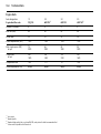
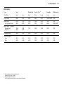
The following Vauxhall child restraint
systems have been approved for
installation in your Vivaro:
Group, weight and age
class1 )
Vauxhall
system
0
From birth - 10 kg,
0 - 10 months
Baby Safe
0+
From birth - 13 kg,
0 - 2 y ears
I
From 9 - 18 kg,
8 m onths - 4 years
Duo ISO FIX
II
from 15 - 25 kg,
3 y ears - 7 years
K id
II I
from 22 - 36 kg,
6 y ears - 12 years
1)
We reco mmen d the use of each system
until th e child reaches the up per weigh t
limit.
If child restraint sy stems of other
manufac ture are to be installed, ensure
that they conform to the appropriate
safety regulations.
9 Warning
Disregard of these instructions m ay lea d
to injuries or endanger life.
The country in w hich y ou are trav elling
ma y prohibit child restraint installation in
certain loc ations. Alway s observ e local or
national regulations.
Seats, interior
43
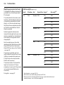
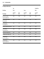
Fro nt seats - all model variants
Group, w eight and age class
Fa cing
directi on
Single seat - front passenger 1 )
w ithout
airbag
with airba g
- no side
airbag
with side
airbag
Benc h seat - front passenger
w ithout airbag
with airbag
centre
outer
centre
outer
0:
0+:
up t o 10 kg or approx. 10 months
up t o 13 kg or approx. 2 yea rs
Rea rw ard
U
U 2)
U 2)
X
U
X
U 2)
I:
9 to 18 kg or app rox . 8 months - 4 yea rs
Forward
U
U 2)
U 2)
UF
U
UF
U 2)
II :
II I:
15 to 25 k g or approx. 3 - 7 years
22 to 36 k g or approx. 6 - 12 y ears
Forward
U
U 2)
U 2)
UF
U
UF
U 2)
1)
2)
If a djusta ble, ens ure seat is in its rearmo st po sition. Make sure vehicle s eat b elt is as stra ight a s pos sib le b etw een sh oulder a nd up per a nchorag e p oint.
En sure the fro nt p as senger’s a irba g s ys tem is d eactiva ted when insta lling a ch ild restra int in this po sition. See p ag e 51.
U =
UF =
X =
Suita ble for u niversal catego ry child restraint system s fo r use in this ma ss g ro up, in conjunctio n with three-p oint seat belt.
Suita ble for u niversal catego ry fo rw ard-fa cing child restraint sys tem s fo r use in this ma ss g ro up, in conjunction with three-p oint seat belt.
Seat po sition n ot s uita ble fo r child ren of this ma ss g ro up.
9 Warning
While using a child restra int system on the front p assenger’s seat, the airbag system s for the front pa ssenger’s sea t m ust be deac tiv ated
(see pag e 51); if not, the triggering of the front or side airbag poses the risk of fatal injury to the c hild.
This is espec ially the case if rea rw ard-facing child restraint sy stems are used on the front passeng er’s seat.
44
Seats, interior
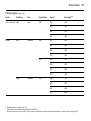
Combi - rear seats
Group, w eight and age class
Facing
direct ion
3rd row bench seat
O uter
Centre
O uter
C entre
U
U,+
X
X
0:
0+:
up to 10 kg or a pprox. 10 months
up to 13 kg or a pprox. 2 y ears
I:
9 t o 18 k g or approx. 8 months - 4 y ears Forwa rd
U
U,+
X
X
II :
II I:
15 to 25 kg or approx. 3 - 7 yea rs
22 to 36 kg or approx. 6 - 12 y ears
U
U
X
X
U =
L =
Suita ble for u niversal catego ry restraint system s for u se in this m ass g roup , in con jun ctio n with th ree-po int sea t b elt.
Suita ble on ly for s pecifica lly ap proved child restra ints. Va uxhall ha s ap proved child restraint systems from th e ’B ab y-s afe’, ’D uo-ISOFIX’ a nd ’Kid’
rang es.
Seat w ith ISOFIX mou nting a va ila ble. Wh en m ountin g ISOFIX, only ISOFIX ch ild restraint systems that h ave b een a pp ro ved for the vehicle ma y be used .
Seat po sition n ot s uita ble fo r child ren of this ma ss g ro up.
+
=
X =
Rea rward
2nd row bench sea t
Forwa rd
Seats, interior
45
Tour - rear seats
Group, w eight and age class
Faci ng
direction
2nd row benc h seat
3rd row bench seat
O uter
Centre
O uter
Centre
0:
0+:
up to 10 k g or app rox . 10 months
up to 13 k g or app rox . 2 years
Rearward
U
U,+
X
X
I:
9 t o 18 kg or approx. 8 m onths - 4 years
Forward
U
U,+
X
X
II :
II I:
15 to 25 kg or ap prox . 3 - 7 y ears
22 to 36 kg or ap prox . 6 - 12 years
Forward
U
U
X
X
U =
L =
Suita ble for u niversal catego ry child restraint system s fo r use in this ma ss g ro up, in conjunctio n with three-p oint seat belt.
Suita ble on ly for s pecifica lly ap proved child restra ints. Va uxhall ha s ap proved child restraint systems from th e ’B ab y-s afe’, ’D uo-ISOFIX’ a nd ’Kid’
rang es.
Seat w ith ISOFIX mou nting a vailab le. When moun ting ISOFIX, on ly ISOFIX child restraint systems th at ha ve b een a pp ro ved for the veh icle ma y b e us ed.
Seat po sition n ot s uita ble fo r child ren of this ma ss g ro up.
+
=
X =
46
Seats, interior
Dou ble Cab - rear seats
Group, w eight and age class
Facing
di rec tion
Rearward
Rea r bench sea t
O uter
C entre
X
X
0:
0+:
up t o 10 kg or approx. 10 months
up t o 13 kg or approx. 2 yea rs
I:
9 to 18 k g or approx. 8 m onths - 4 years Forward
X
X
II :
II I:
15 to 25 k g or approx. 3 - 7 years
22 to 36 k g or approx. 6 - 12 years
X
X
X =
Seat po sition n ot s uita ble fo r child ren of this ma ss g ro up.
Forward
Seats, interior
47
When triggered, the driver’s airbag a nd
front passeng er’s airbag 3 inflate in
milliseconds and form safety cushions for
the driver a nd front pa ssenger. The
forward m ov ement of the driver and front
passenger is c hecked and the risk of
injuries to the upper body and head are
thereby substantially reduced.
z No impa irm ent of view will occur,
beca use the airbags inflate and deflate
so q uick ly .
9 Warnin g
Airbag systems
Front airb ags
The front airbag system is identified by the
word “Airbag ” on the steering w heel and
above the glov e c om partment 3.
The front airbag system comprises:
z An airbag with an inflator in the steering
wheel, and a second one behind the trim
panel ab ov e the glove compartment 3.
z The control elec tronics with impact
sensor.
z The airbag system control indicator v in
the instrument cluster.
z Front passenger airba g deactivation 3.
The front airb ag system is triggered:
z Depending on the severity of the
accident.
z Depending on the ty pe of impact.
z Within the range shown in illustration
S 11741.
z Independently of the side airbag 3 and
curtain airbag system s 3.
Exa mples:
z Imp act against a non-yielding ob stacle:
the front airbag is triggered at low
vehicle speed.
z Imp act against a yielding obstacle (suc h
as another vehicle): the front a irb ag is
only triggered at a higher vehicle speed.
The front airbag system provides
optimum protection when the seat,
backrest and head restraint are correctly
adjusted. Adjust the driver's seat
according to the occ upa nt's height such
tha t with the driver sitting upright, the
steering wheel is held in the area of its
up per spokes with the driver's arm s
slightly b ent. The front passenger’ s seat
should be as far back as possible, with
the back rest upright. Do not place the
head, body , ha nds or feet on the cover of
the airbag sy stem.
Do not place any objec ts in the area in
which the airbags inflate.
The three-point seat belt must b e
correctly fitted (see page 39).
48
Seats, interior
The front airbag system will not be
triggered in the event of:
z The ignition b eing switched off.
z Minor frontal collisions.
z Ac c idents in which the vehic le overturns.
z Collisions involving a side or rear-imp act
where it would not be of b enefit to the
occ upa nts.
9 Warning
Seat belts m ust therefore a lways be worn.
The front a irb ag system serv es to
supplement the three-point seat belts. If
you do not wea r your seat belt you risk
being seriously injured, or even thrown
from the vehic le, in the ev ent of an
accident.
The belt helps to keep y ou in the correct
seating position, in which the front airbag
system will provide you with effective
protection in the event of an ac cident.
Side airb ags 3
The side a irb ags are m ounted on the
outboard sides of the front seat backrests
to protect the oc cup ants in the event of a
severe side-imp act.
The side a irb ag system c om prises:
z An airbag with inflator in the bac k of the
driver's a nd front passenger's seat
respectively .
z The control electronics.
z Sid e-impact sensors.
z The airbag system s control indica tor v in
the instrum ent cluster.
The side airbag sy stem will be triggered:
z Depending on the severity of the
accident,
z Depending on the type of impa ct.
z Within the range shown in illustra tion
S 11743.
z Independently of the front a irba g
sy stem.
Seats, interior
49
When triggered the side airbag inflates in
milliseconds and forms a sa fety cushion for
driver and/or front passenger in the
respective door area. The risk of injury to
the upp er body in the event of a sideimpac t is thereby substantially reduc ed.
9 Warning
There m ust be no objects in the area in
which the airbag inflates or in the area
between the seat back rests a nd the
vehicle body. Do not place the hands or
arms on the covers of the airbag systems.
Important information - see pag e 52.
Curtai n airbag s 3
The curtain airbag system is identified b y
the badge AIR BAG on the headlining trim.
The curtain a irba g system w ill be trigg ered :
z Depending on the severity of the
accident.
The curtain airbag system comprises:
z An airbag w ith inflator in the roof fram e
on the d riv er’s and p assenger’s side
respectively .
z Depending on the type of impa ct.
The sid e airbags w ill not be trigg ered in the
event of:
z The ignition b eing switched off,
z Frontal collisions.
z The control electronics.
z Ac c idents in which the vehicle overturns.
z The side-impact sensors.
z Collisions inv olv ing a rea r-im pact.
z The airbag system s control indica tor v in
the instrum ent cluster.
The three-p oint sea t belt m ust be
correctly fitted - see page 39.
z Collisions inv olving a side-impact outside
the passenger c ell.
z Within the range shown in illustra tion
S 11743.
z Tog ether w ith the sid e airbag sy stem.
z Independently of the front a irba g
sy stem.
50
Seats, interior
When triggered the curtain airbag inflates
within milliseconds and provides a safety
barrier in the head area on the respective
side of the vehicle. This reduces the risk of
injury to the head considerably in the ev ent
of a side-im pact.
9 Warnin g
Have the c ause of the fault rem edied by
a workshop .
The system's integral self-diagnosis facility
allows faults to b e q uick ly rem edied.
9 Warning
There m ust be no objects in the area in
which the airbag inflates. Do not place
the hands or arms on the covers of the
airb ag systems. I mportant information –
see pa ge 52.
The three-point seat belt m ust always be
correctly fitted – see page 39.
The curtain airbags will not be triggered in
the event of:
z The ignition b eing switched off.
z Frontal collisions.
z Ac c idents in which the vehicle overturns.
z Collisions inv olv ing a rea r-im pact.
z Collisions inv olving a side-impact outside
the passenger c ell.
Airbag control ind icator v
The front airb ag system, side airbag
sy stem 3 and curtain airba g sy stem 3 a re
monitored electronica lly together with the
belt tensioners, and their operational
readiness shown by the control indicator v
in the instrument c luster. When the ignition
is switched on, the control indicator
illuminates then extinguishes. I f it d oes not
illuminate, or if it illuminates while driving,
there is a fault in the airbag system s or the
belt tensioners.
The systems might not be triggered in the
event of an accident.
Seats, interior
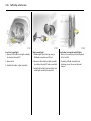
Fro nt passenger airbag
deactivation 3
Front and side airbag sy stems must b e
deactivated if a child restraint sy stem is to
be mounted on the front passenger’ s seat.
The b elt tensioners as well as a ll airbag
systems for the driv er’s seat remain active
when the front p assenger seat’s airbag
systems are disengaged.
The switch for deactivating or activating
the a irb ag system is located on the front
passenger’s door.
The chosen setting remains ac tiv e after the
ignition has been switched off. Control
indicator H for front passenger airbag
deactivation is loc ated in the instrument
cluster.
To dea ctiv ate:
With the front passenger’ s door open,
press switch in and rotate anticloc kwise to
the "O FF" position.
The airbag sy stems for the front
passenger’s seat are now deactivated.
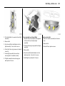
51
With the ignition switched on, the control
indicator H w ill remain illuminated to
indicate dea ctivation. It is now safe to
place a child restraint on the front
passenger’ s seat.
52
Seats, interior
To act ivat e:
Ensure the airbag system s for the front
passenger’s sea t are activated when a
passenger of a dult size occupies the front
passenger’s sea t.
With the front passenger’s door open,
press switch in and rotate c lock wise to the
"O N" position. Front p assenger’s airbag
systems are now activated and w ill be
triggered in the event of an accident.
Upon switching the ignition on, control
indicator H will illuminate briefly and then
exting uish, indicating that the front
passenger’s airba g is active.
If control indicator H rem ains illuminated
in conjunc tion w ith control indica tor v, this
indicates a fa ult w ithin the sy stem.
9 Warning
Have the cause of the fault remedied by
a workshop.
Imp or tant
z Accessories not released for your v ehicle
type and other objects must not be
affixed or placed in the area in which the
airbags inflate, as they could cause
injury when the airbags are triggered.
z Do not place any objects between the
airbag sy stems and the v ehicle
occupants; risk of injury.
z Do not stic k or place anything on the
steering wheel, instrument p anel, front
seat b ackrests in the vic inity of the
airbags and seat areas or c ov er them
with other m aterials.
z The airb ag systems and b elt tensioner
control electronics can be found in the
centre console area . In order to avoid
malfunctions, d o not store magnetic
objec ts in this area.
z Use only a dry cloth or I nterior /
Upholstery C leaner to clean the steering
wheel, instrum ent panel, front seat
back rests, roof frame and seat area of
the front passenger’ s seat. Do not use
any aggressiv e c leaning agents.
z Only protective covers which are
approved for your Viv aro with side
airbag 3 may be fitted on the front
seats. When fitting the protective covers,
make sure that the a irb ag units on the
outboard sides of the front seat
backrests are not covered.
z The airbag sy stems are triggered
ind epend ently of each other depending
on the severity of the accident a nd the
type of im pact. The side airbag system 3
and the c urtain airbag sy stem 3 are
trig gered together.
z Each airbag can be triggered only once.
Once triggered, an airb ag must be
replaced without dela y by a workshop .
z The speeds, directions of movement and
deformation properties of the vehic les,
and the p roperties of the obstacle
conc erned, determ ine the severity of the
accident and triggering of the airbags.
The degree of dama ge to y our vehicle
and the resulting repair costs alone are
not indica tiv e that the criteria for
trig gering of the sid e airbag 3 were met.
Seats, interior
z Do not perform any m odifica tions to the
com ponents of the airbag system s, as
this will render the vehic le unroadw orthy.
9 Warnin g
While using a child restraint sy stem on
the front passeng er’s seat, the airbag
sy stems for the front passenger’s seat
must b e d eactivated; if not, the
trig gering of the front or side a irb ag
poses the risk of fatal injury to the child.
9 Warning
The systems can be triggered ab ruptly
and cause injury if they are handled
im properly.
z We recom mend hav ing the steering
wheel, the instrument p anel, all panelling
parts, the door seals, the hand les and
the front seats removed by a workshop
in the ev ent of triggering of the airbags.
z When disposing of the v ehicle, please
ob serve the applicab le safety
regulations. Please have the vehicle
disposed of by c om pany which reuses
vehicle parts.
9 Warning
Child restraint sy stems as well as other
heavy objects must never be carried on
the lap of passengers; risk of fa tal injury.
53
This is especially the case if rearwardfacing child restraint systems are used on
the front passeng er’s seat.
The system for deactivating the front
passenger seat’s airba g systems is
indica ted a stick er on the side of the
instrument panel, visible when pa ssenger’s
door is open.
54
Seats, interior
Installing (front or rear position)
Lift the covers to access the mountings,
insert the load comp artm ent net rod into
the mounts a nd secure. Attac h the stra ps
to the lashing eyes behind the front sea ts;
or to the rings on the rear seat frame, then
tension the straps.
Rem oving
Tilt strap length adjuster upwards and
unhook strap.
9 Warning
Load c ompartm ent net 3
The load compartment net can b e fitted
behind the front or rear seats to sepa ra te
compartments when transporting luggage
or animals.
Loose objects in the load compartment
should b e sec ured safely.
Load compartment cover 3
To remov e:
Lift cover and disconnect from the side
guides.
Not es on load ing
S ee page 56.
9 Warnin g
Do not p la ce a ny heavy or sharp ob jects
on the cover.
Loose objects in the load com partment
should be secured safely.
Seats, interior
55
z loa ds can then be secured in position
using lashing straps 3 attached to the
anchorage point.
The maximum load of ea ch anchorag e
point is 75 kg . To prev ent the p ossibility of
exceeding this maxim um , the use of
ratchet type lashing straps is to be
av oided.
9 Warnin g
Loose objects in the load com partment
should be secured safely.
Lashing eyes
Lashing eyes a re mounted in the load
compartment to enab le loads to be
secured in position using la shing stra ps 3
or a luggag e floor net 3.
The ma ximum force ap plied to the lashing
eyes should not exceed 5000 N at 30 °.
Load anchorage ra ils 3
Load a nchorage rails mounted in the load
compartment, provide adjustable
anchorage points for securing loads.
z Release centre p in of the anchorage
point, by pulling out against spring
tension,
z slide the anc horage p oint to the required
location,
z position the anchorag e point directly
over the nearest suitable "locking hole",
z release the centre pin of the anchorage
point, ensuring the pin is located
correctly and the anchorage point is
securely locked,
56
Seats, interior
Notes on load ing the vehicle
z Heav y objec ts in the load compa rtm ent
should be placed as far forwards as
possible. If objects are to be stacked , the
heavier objects should be placed a t the
bottom. Unsecured ob jects in the load
com partment would be thrown forwards
with great force in the event of heavy
braking, for example.
z Secure heav y objec ts with lashing
straps 3 atta ched to the lashing eyes.
If heavy loads slip when the vehicle is
braked heavily or driven around a bend,
the handling of the vehicle m ay change.
z Secure loose items in loa d compartment
using luggage floor net 3, to prev ent
sliding.
z When transporting objects in the load
com partment, fit loa d compartment
net 3 - see page 54.
z Close the load com partment cov er 3, to
prevent the objects from being reflected
in the rear wind ow .
z If the rear seats a re not folded down 3 or
removed 3 when tra nsporting objects in
the load comp artment, they must be
engaged in their upright position see pa ge 34.
z The warning triangle 3 and first-aid kit 3
should a lways be freely accessible.
z Weights, payload and roof loa d see page 166.
z No objects should be placed on the load
compa rtm ent cover 3 or the instrument
panel. They are reflected in the g lass,
obstruct the driver’s view and will be
thrown through the vehicle in the event
of heav y brak ing, for ex ample.
z Driv ing with a roof load (also see
page 97) increa ses the sensitivity of the
vehicle to crosswinds and has a
detrimenta l effec t on vehicle handling
owing to the higher centre of gra vity of
the vehicle.
z No objects should be stored in any of the
airbag 3 inflation zones, as injuries m ay
be caused w hen the a irba g is trig gered.
z The load m ust not obstruct the operation
of the p edals, handbrak e and gearshift
lever, or hinder the freedom of
movement of the driver. Do not place
any unsecured objects in the interior.
z Bulky ob jects should not be transported
with the rear doors open or ajar,
otherwise poisonous exhaust fumes may
enter the vehicle. In addition, the number
plate is only distinguisha ble and
illuminated correctly if the doors are
closed.
9 Warnin g
Disregard of these instruc tions may lead
to injuries or endanger life. Vehicle
passeng ers must be informed
accordingly.
Seats, interior
O ver-cab stora ge area 3
The total weight in this com partment must
not ex ceed 30 kg.
57
Ashtray
Drink holders
Remova ble to enable universa l use for
driver or p assengers.
To use drink holders, remove the ashtray
unit.
To be used only for ash and not for
combustible rubbish.
9 Warning
Disregard of these instructions m ay lead
to injuries or endanger life. Vehicle
passengers must be informed
accordingly.
To op en: lift up the cover.
To empty : remove the ashtra y from the
drink hold er recess and em pty.
58
Seats, interior
Warning triangle ¨ 3,
First-aid kit + 3
Your first-aid kit and w arning triangle can
be accomm od ated in the space under the
front seats.
9 Warning
Ensure items stowed under the seats a re
securely restrained.
Power outlets
Ciga ret te lighter )
With ignition switched on, press in the
cigarette lighter. H eating up ceases once
element is glowing. Withdraw lighter.
Accessory socket
The soc ket for the cigarette lighter ca n be
used to connect electrical acc essories when
the ignition is switched on.
An ad ditional accessory socket 3 is loc ated
in the rear of the vehicle.
When the eng ine is not running, using these
acc essory sockets will ca use the battery to
be discharged.
The maximum power requirement of
electrical ac cessories m ust not ex ceed
120 w atts.
Do not connect any current-delivering
acc essories, e.g. electrical charging
devices or b atteries.
C onnected electrical accessories must
comply with the EC standard in terms of
electromagnetic compatibility
requirements laid down in DIN VDE 40 839,
otherwise vehicle malfunc tions may occur.
The use of non-authorised accessories may
cause damage to the socket.
Instru men ts, c ontrols
59
Instruments, controls
Control indicators .... ..... .... ..... .... .... .....
Instrument display ... ..... .... ..... .... .... .....
Multi-function display .. .... ..... .... .... .....
Trip computer 3 .. .... ..... .... ..... .... .... .....
Engine oil life monitor 3 ... ..... .... .... .....
Triple Information Display 3 .... .... .....
O utside temperature.... .... ..... .... .... .....
C olour Information Display 3 ... .... .....
Warning buzzers.. .... ..... .... ..... .... .... .....
Wind screen wiper .... ..... .... ..... .... .... .....
Wind screen wash system . ..... .... .... .....
Rear door and tailgate window wash
wipe sy stem 3 ... .... ..... .... ..... .... .... .....
59
62
64
65
68
68
69
70
74
74
75
Control indic ators
75
9
The control indica tors described here are
not present in all vehic les. The descriptions
however, apply to all instrument versions.
The colours of the control indicators m ean:
z Red
Dang er, im portant reminder,
z Y ellow Warning, information, fault,
z Green Confirma tion of ac tiv ation,
z Blue
Confirma tion of ac tiv ation.
Ü
Not used
Hea dlight dipped bea m
Illum inates in green when dipp ed b eam is
on - see pages 10, 76.
P
Headl ight m ain beam , hea dlight fl ash
Illuminates in blue when m ain beam is on
and w hen headlight flash is operated see pages 10, 76.
r
Fog tai l light
Illuminates in yellow when the fog tail light
is switched on - see pa ges 10, 78.
>
Front fog li ghts 3
Illuminates in green w hen front fog lights
are switched on - see pa ges 10, 78.
u
Anti -lock Bra ke Syst em (ABS )
C ontrol indicator illuminates in yellow see page 112.
60
In struments, controls
8
Diesel p artic le fi lter 3
Illuminates in yellow when regeneration
of diesel particle filter is required see page 106.
A
F
Not used
V
v
ESP®P lus 3
(Electr oni c Sta bility Program me)
Control indicator illum inates in yellow see page 108.
F
Eng ine oi l life monit or 3
Control indicator illum inates in yellow in
transm ission display - see pages 68, 107.
kg
Easytronic , La den program me 3
Illuminates in yellow in transm ission display
when Laden programme is enabled see page 94.
T
Easytronic , footbrak e appl ication 3
Control indicator illum inates in yellow in
transm ission display - see page 91.
W
Easytronic , transmission electronics 3
Illuminates in yellow briefly when ignition
is sw itched on. Illuminates in transmission
display w hen fault has occ urred see page 96.
Easytronic, A ut omatic mode 3
Illum inates in y ellow in tra nsmission d isplay
when Autom atic mode is selected see p age 92.
Easytronic, Winter p rogramm e 3
Illum inates in y ellow in tra nsmission d isplay
when Winter programm e is enab led see p age 93.
O
Turn sig nal lig ht s
The corresponding control indicator
flashes in green when the turn signal light is
on.
Flashes rapidly: a turn sig nal bulb has
fa iled.
An audible warning can be heard when the
turn signal lights are on. When towing a
caravan or trailer, the pitch of the audible
warning chang es.
Turn signal lights - see pages 10, 78.
Bulb replacement - see page 140.
C
Stop engine
If control indicator C illuminates in red, in
conjunction with p, I, E or R, stop
engine im med ia tely a nd consult a
work shop.
o
Electronic im mobi liser
If the control indicator flashes in red when
the ignition is on, there is a fault in the
imm ob iliser sy stem; the engine cannot b e
started - see page 18.
A
Serv ice / Engine electronics 3
If control indicator A illuminates in yellow,
in conjunction with u or v, interrupt y our
journey. Consult a work shop.
D
Prehea ting / Fuel fi lter / Engine
electronics 3
Illuminates in y ellow briefly during engine
preheating - see pag e 14.
If illuminated continuously it indicates:
z The presence of wa ter in the diesel fuel
filter 3. Drain diesel fuel filter of residual
water - see page 154.
z An electronic system failure: consult a
workshop.
Instru men ts, c ontrols
Y
I
Fuel l ev el
If it illuminates in y ellow:
fuel level low , fill up.
Engine oil p ressure
Illum inates in red when ignition is switched
on. Ex tinguishes after a short period of
tim e. Can illuminate intermittently when
idling with hot engine; must extinguish
when engine speed is increased.
Never let the tank become empty !
With diesel engines, it is not possible to
start the engine after the ta nk has been run
empty. The fuel system must b e b led first.
Further information - see pages 102, 164,
170.
E
Eng ine st op
Will illuminate in red in conjunction with C
engine if coolant temperature is too high.
Stop v ehicle and consult a workshop.
p
Alternat or
Illuminates in red when ig nition is switched
on. Extinguishes after engine is started.
If illuminated while driving:
Stop v ehicle and switch off engine. The
battery is not being charged and the
engine cooling may be interrupted. The
brake servo unit may c ease to be effective.
Interrupt your journey and check d riv e belt
condition and tensioning before
contacting a workshop.
If illum inated while driving:
Engine lubrication may be interrupted,
resulting in da mage to the engine and/or
lock ing of the driving w heels:
z Move out of the flow of traffic as quickly
as possible without imped ing other
vehicles,
z Depress clutch,
z Move gearshift lev er to neutral, or with
Easy tronic 3 place selector lever in N,
z Sw itch off ignition (to position A).
C onsiderably greater force will be
req uired for braking a nd steering.
9 Warning
Do not rem ov e key until vehicle has come
to a standstill, otherwise the steering
column loc k could eng age unex pectedly.
Check engine oil level before consulting a
work shop. If the eng ine oil lev el is low, top
up using the specified engine oil - see
pages 150, 164.
If the engine oil level is normal, hav e a
work shop check the vehicle’s lub ric ating
sy stem.
61
R
Brak e system
Illuminates in red w hen ignition is switched
on if ha ndb ra ke is applied and/or fluid level
for brake hydraulics is too low .
9 Warnin g
If it illuminates when the handbrak e is not
applied : stop vehicle; interrupt y our
journey immediately . C onsult a
workshop.
Further information - see pag es 111, 156.
v
Airb ag system s, bel t tensioners
C ontrol indicator illuminates in yellow see pages 37, 47.
H
Front passenger airba g deact ivati on 3
Illuminates in y ellow when the ignition is
switched on and remains illuminated when
the front passenger’ s a irb ag has been
deactivated.
If c ontrol indicator H is illum inated in
conjunction with v or A, consult a
workshop.
Further information - see pag e 51.
62
In struments, controls
X
Not used.
U
Door open 3
O perational only when ignition is switched
on. Illuminates in red when d riv er’s door,
passenger’s door or side loading doors are
open.
U
Not used.
Z
Exhaust emissions 3
Illuminates in yellow when ig nition is
switched on. Extinguishes shortly after
engine sta rts.
If it illuminates when the eng ine is running:
Fault in emission control sy stem. The
permitted emission limits may be
exceeded. C onsult a workshop .
If it flashes when the engine is running :
For fault that can lead to destruction of the
cataly tic conv erter, see page 104. C onsult
a w orkshop imm ediately.
B
In strument display
Ta chometer
Making use of the tachom eter helps to
sav e fuel; it indicates the engine speed in
revolutions per minute.
Warning zone on rig ht: maxim um
permissib le engine speed exceeded;
danger to engine.
Sp eedom et er
Indicates the vehicle speed.
C ertain model variants feature a speed
regula tor 3 1) which restric ts the vehicle
ma ximum speed. As a visible indication of
this, a wa rning label is located on the
instrument panel.
If possible, drive in ea ch gear in the low
engine speed ra ng e (between approx.
2000 and 3000 rpm ) and maintain an even
vehicle sp eed.
Not used
1)
Depen ding o n d riving enviro nment (e.g . w hen
descend in g steep inclines ), the veh icle speed
ca n exceed set limits. In such instances, it
rem ains the driver’s resp ons ib ility to a dhere to
the s pecific sp eed limits .
Instru men ts, c ontrols
For physical reasons, the coolant
temperature gauge shows the coolant
temperature only if the coolant level is
adequate.
Fuel g auge
Display of fuel level:
Coolant tem perature gaug e
Display of coolant temperature:
Illumination of bars display s fuel lev el.
Bars illuminated =
in lower area
When fuel ga uge indicates fuel supply is
low, fuel warning control indicator Y
illuminates = fill up. See pag e 102.
Never let tank become empty!
Bars illuminated =
up to central
area
Bars illuminated =
in upp ermost
zone or control
indicator E
illuminates 3
Engine operating
temp erature not y et
reached.
Normal operating
temp erature.
Temp erature too
high. Stop v ehicle,
sw itch off engine.
Danger to engine.
Chec k coolant level.
See p age 155.
63
64
In struments, controls
Multi-function display
Transmission displ ay 3
Display of the selected gear a nd mode with
Ea sy tronic.
N
R
A
kg
V
T
W
Neutral or idling position.
Reverse gear.
Automatic mode.
Laden programme.
Winter prog ra mme.
Footbrake application.
Transmission electronic s.
Engine oil l ev el display
The engine oil level d isplay is correct only if
the vehicle is parked on level g round with a
cold engine. The engine oil level display will
only be reset if the ignition has been
switched off for more than two m inutes.
If "O IL" appears in the display, the eng ine
oil level may need topping up. To gain a
more ac curate indication of the engine oil
level, press and hold the reset button - see
page 67.
The squares that a ppear in the display
indicate the engine oil level. As the engine
oil level d iminishes, the sq ua res in the
display disap pear a nd are replaced with
dashes.
1)
A:
Max im um lev el
B:
C:
Intermediate level
Minimum level = check and top up
engine oil1)
Co ntrol ind icator A illum in ates if
engine o il level is to o low.
To return to the norma l disp la y, p ress the
reset button a gain.
C hecking and topp ing up fluids see page 150.
Instru men ts, c ontrols
Elec tronic odom et er / c l ock
In normal m od e, the odometer and clock
are visib le.
The reset button is loca ted alongside the
speedometer. Press button once to d isplay
the trip od om eter.
Press the button and hold; the disp la y will
flash and after 1 second w ill reset to zero.
Press the button again to return the
odometer to normal m od e.
To adjust the clock:
With the disp la y in norm al mode, press and
hold the b utton, and the minutes rea ding
will begin to increase.
After the button is released, the clock will
continue to flash for a further 5 seconds to
enab le further adjustments to be made.
Trip computer 3
In addition to the electronic odometer
functions, the trip comp uter can also
display additional monitored vehicle data,
including;
z
z
z
z
z
z
Fuel used.
Average consumption.
Instanta neous consum ption.
Range.
Distanc e travelled .
Average speed.
Pressing the selection switch located on the
end of the windscreen wash stalk will cy cle
through these display s.
65
Fuel used
Displays the a mount of fuel consumed
since the last reset.
The m easurement can be restarted at a ny
time – see " Reset trip computer
inform ation" on page 67.
66
In struments, controls
Averag e c onsum ption
Average consumption is display ed, taking
into consideration the dista nce travelled
and the fuel used since the last reset.
The m easurement can be restarted at any
time - see "Reset trip computer
inform ation" on page 67.
Instantaneous consumption
The value is display ed after reaching a
speed of 15 mp h (25 km/h).
Ra ng e
The ra ng e is calculated from the c urrent
contents of the fuel ta nk and the averag e
consum ption since the last reset see "Reset trip comp uter informa tion" on
pag e 67.
The range will not be displayed if fuel level
control ind icator Y is illuminated.
Instru men ts, c ontrols
67
Distance tra velled
Displays the distance driven since the last
reset.
Average speed
The average speed is displa yed, since the
last reset.
Reset trip computer inform ation
To reset the trip com puter, select one of its
functions then press the reset button.
The m easurement can be restarted at any
time - see "Reset trip computer
inform ation".
The measurement can be restarted at any
tim e - see "Reset trip computer
information".
The following trip com puter inform ation
will b e reset:
Stoppages in the journey with the ignition
off are not includ ed in the calculations.
z
z
z
z
z
Fuel used.
Average consum ption.
Range.
Distance travelled.
Average speed.
I nt err up tion of pow er supp ly
If the power supp ly has been interrupted or
if the battery voltage ha s dropped too low,
the values stored in the trip computer w ill
be lost.
68
In struments, controls
Engine oil life monitor 3
Triple In formation Display 3
Ea ch time the ignition is switched on, the
rem aining distance b efore the next engine
oil and filter cha nge is due may be shown
in the d isplay for approx. 5 seconds.
Display for time, outside temperature,
ra dio / date.
Within 1800 miles (3000 k m) of the nex t
engine oil change being due, the rema ining
distance and control indicator F will
illuminate in red for approx. 30 seconds as
a reminder. Make an appointment with a
workshop for service work as soon as
possible.
Further information - see page 107.
When the ignition is off, the time, date and
outside temperature can b e m ade to
appea r for approx. 15 seconds by briefly
pressing one of the two buttons beside the
display .
Sett ing dat e a nd tim e
S witc h off rad io. Press Ö and ; beside
display as follows:
Press Ö for a pprox. 2 seconds:
Day flashes
; : S et day
Ö : Month flashes
; : S et month
Ö : Y ear flashes
; : S et year
Ö : Hours fla sh
; : S et hours
Ö : Minutes flash
; : S et minutes
Ö : C lock sta rts at 0 seconds.
Instru men ts, c ontrols
If only the time is to b e set, repeated ly
press Ö with disp lay in setting mode until
hours / minutes flash.
Autom atic d ate and t ime set ting 3
Possible in the case of radio reception from
RDS stations1 ) which broadca st a time
signa l.
Autom atic setting is carried out once the
radio has been switched on a nd an RDS
time sig nal ha s b een receiv ed. The setting
is indicated by } in the display. If no time
signa l is receiv ed, or the time signal is
inaccurate, the date and tim e must be set
manually.
Dea ctivating and activa ting the automatic
setting func tion (e.g. if a n inac curate time
signa l is receiv ed from the broadcasting
station):
Press Ö
for approx . 2 seconds; the time
display is now in setting mode.
Press Ö
twice (until year flashes).
Press Ö
for approx . 3 seconds until } in
display fla shes and the display
“RDS TIME” appears (y ears
flash while button is depressed).
Press ;
Press Ö
1)
Display indica tes:
RDS TIM E 0 = Deactivated
RDS TIM E 1 = Ac tiv ated
three times.
RDS = Ra dio Da ta Sys tem .
69
Fault displa y
Display --.-°C or an F in the d isplay
indica tes a fault. Ha ve the cause
eliminated , consult a workshop.
Interruption of p ower supply
If the power supply has been interrup ted or
if the battery voltage has dropped too low,
the date and time must be reset.
When the battery has been reconnected or
cha rg ed, set the d ate a nd time as
described und er “Setting date and time”.
In the ca se of radios w ith RDS 3, the tim e is
set automatically w hen the radio is
receiving an R DS station which broadcasts
a time signal.
Outside temperature
A fall in tempera ture is ind icated
imm ediately and a rise in tem perature
after a time dela y.
9 Warnin g
Caution: The road surface may already
be icy even though the d isplay indicates
a few deg rees ab ov e 0 °C .
If the ex ternal temp erature falls to 3 °C, to
warn of ice on the road the : sym bol
app ears in the Triple Inform ation Display.
When the temperature climb s, the :
symbol extinguishes above 5 °C.
70
In struments, controls
Colour In formatio n Display 3
Selec ting functi ons
Functions and their menus are shown in the
information display.
Slippery road
-2, 5°C
OK
In vehicles with C olour Information
Display 3 , a warning message app ears in
the d isplay as a wa rning for icy roa d
surfaces. There is no m essag e below -5 °C
9 Warning
Caution: The road surface may already
be icy ev en though the display ind ic ates
a few degrees above 0 °C .
These functions a re marked or ex ecuted in
the menu display via the four-wa y button,
the multi-function knob 3 on the
Infotainment sy stem or buttons 3 on the
steering wheel.
To select w ith four-way button:
Select menu items via menus and
with the buttons / four-w ay button of
the Infotainm ent system.
S elec tion with the multi-function knob 3:
Turn
Press
Mark m enu item s or c om mands,
selec t functions.
Select m arked item,
confirm command.
To exit a m enu, turn the m ulti-func tion
knob left or right to Return or Mai n
and select.
Instru men ts, c ontrols
7
FM
[TP]
�
C Din
Settings
T ime, Date
71
19,5° 19:36
19:36
Language
90.6 MHz
Units
10 . 07 . 2004
Contrast
Day / Night
19,5°
Selection using buttons 3 on steering
wheel:
Select menu options v ia menus and
with the b uttons.
19: 36
For each functional area there is a main
page (Main), which is selected at the top
edge of the display (not with Infotainment
System CD 30):
z Audio.
z Na vigation 3.
Function areas audio and nav igation 3
– see Infota inm ent system operating
instructions.
6 Ign. logic
System settings
The settings are accessed via the Setting s
menu.
Press the Ma in button 3 (not found on all
Infotainment sy stems) on the Infotainm ent
system (c all up main display).
Press the S ett ings button on the
Infotainment system. For I nfotainment
S ystem C D 30, no menu ma y be selected.
The Settings m enu is displa yed.
72
In struments, controls
7
T ime, Date
T ime
D ate
19,5° 19:36
19:36
10 . 07 . 2004
6 Synchron. clock automatical.
7
Settings
19,5° 19:36
7
13 Languages
19,5° 19:36
X Deutsch
T ime, Date
Language
Deutsch
English
Units
English
Español
Contrast
Español
Dutch
Day / Night
...
French
6 Ign. logic
Italiano
Setti ng date and time
Select menu item Time, Dat e, from the
Setti ng s menu.
Lang uage selecti on
You can select the d isplay language for
some func tions.
S elec t the desired language.
The m enu for Time, Date, is d isplay ed.
Select menu item Lang ua ge from the
Settings menu.
In system s w ith v oic e output 3, when the
language setting of the display is changed
the sy stem will ask w hether the
announcement lang uag e should also b e
changed – see Infotainment system
operating instructions.
Select the menu items required:
Make the desired setting.
Corr ect ing tim e 3
Some RDS transmitters 1 ) do not send
correct tim e signals. If the incorrect time is
frequently displayed, deactivate
automatic time synchronisation 3 and set
the tim e m anually .
To correct time with the help of R DS, select
menu item S ynchron. c lock a ut omati cal.
from the Ti me, Date, m enu.
1)
RDS = Ra dio D a ta System.
The ava ilab le languages are d isplay ed.
S elec tions are indic ated b y a 6 in front of
the menu item.
Instru men ts, c ontrols
7
Settings
19,5° 19:36
Time, Date
Language
Units
Contrast
Day / Night
~
|
|
|
Europe-SI
Japan
Great Britain
USA
6 Ign. logic
Setti ng units of measure
You ca n select w hich units of measure a re
to be used.
Select menu item Units from the Settings
menu.
The a vailable units are disp la yed .
Select the desired unit.
Selections are indicated by a o in front of
the m enu item .
Setting d isplay mode 3
The display c an be adapted to light
conditions: Dark c oloured text on a light
background or light coloured text on a
dark bac kground.
Select menu item Da y / Nig ht from the
Settings m enu.
The options are displayed.
Automat ic:
Ad apted based on v ehicle lig hting.
Always day desi gn:
Dark coloured text on light back ground.
Always night design:
Light coloured text on da rk back ground.
Selections are indicated by a o in front
of the menu item.
Ign. log ic 3
See Infotainment system operating
instructions.
2
73
19,5° 19:36
00:00:00
Timer
Start
Reset
Options
St opwat ch 3
Press BC b utton on the I nfotainment
system
The Ti mer menu is display ed.
To start, select menu item S tart.
To reset, select menu item Reset.
74
In struments, controls
The stopw a tc h informa tion to be displayed
can be selected via menu Opt ions 3:
Warn ing buzzers
Driv ing Time exc l. Stop s
Measurement of the tim e the vehicle is in
motion. Stationary tim e is not includ ed.
z While operating the turn signal lig hts.
Driv ing Time incl. Stops
Measurement of the tim e the vehicle is in
motion. The tim e the vehicle is stationary
with the k ey in the starter switch is
included.
Trav el Ti me
Measurement of the tim e from m anua l
activation v ia S tart to manual deactiva tion
via Reset.
While driving:
z During illum ination of low fuel control
indicator Y .
z Easy tronic 3 : with high clutch
temperatures.
When the vehicle is parked and driver’s
door is opened:
z If the key is in the starter switch.
z If the headlights are switched on.
z Easy tronic 3 : if neutral is not selected,
footbrake is not depressed or handbrake
is not applied .
Win dscreen wiper
Driv ing hints - see page 97,
Save fuel, protect the environment see p age 99.
1
2
To activa te, move stalk downwards.
K
=
=
=
Timed interval w ipe
Slow
Fast
Return the stalk to its original p osition to
turn off.
Instru men ts, c ontrols
Autom atic w iping with ra in sensor 3:
To activate, m ov e stalk d ow nw ards to
automatic wiping with ra in sensor
position K .
The rain sensor detects the am ount of
water on the windscreen a nd automatically
reg ulates the windscreen wiper frequency.
The sensitivity of the sy stem can b e
adjusted by rotating the ad juster ring:
Less sensitive
=
More sensitive =
Rotate adjuster
forwards
Rotate adjuster
bac kwards
Upon starting the engine, automatic
wiping will need to be reselec ted.
Further information - see pages 143, 158.
Windscreen wash system
To activate, pull sta lk towards steering
wheel.
Short pull
The wiper operates for one cycle.
Long p ull
Wash fluid is spray ed onto the windscreen,
at the same time the wip er is operated for
four cy cles.
Check regularly that the windscreen wash
sy stem is operating efficiently.
On vehicles with rain sensor 3, keep the
sensor area clean by operating the wa sh
sy stem reg ularly .
Further inform ation - see page 159.
75
Rear door and tailgate window
wash wipe system 3
To activa te, rotate switch.
0
e
f
=
=
=
O ff
Wiper
Wash
Wash fluid is sprayed onto the w indow
when the stalk is moved to the second
position. The switch is spring loaded and
will return to the ’wiper’ position w hen
released.
C heck regularly that the wind ow wash
system is operating efficiently.
Further information - see pag es 158, 159.
76
Ligh ting
Lighting
Vehicles with d aytime running lights 3:
When the ig nition is on, the dipp ed bea m is
on and the instrument illumination is
subdued.
The daytime running lights ex tinguish
when the ignition is switched off.
Follow the regula tions of the country in
which you are driving w hen using da ytime
running lig hts and front fog lights 3.
Driving ab road - see page 80.
Ex terior lights .. ..... .... ..... .... ..... .... .... .....
Main beam, headlight flash . .... .... .....
Autom atic dipped beam a ctivation 3
Turn signal lights . .... ..... .... ..... .... .... .....
Fog tail light r, front fog lights > 3
Reversing lights.... .... ..... .... ..... .... .... .....
Haza rd warning lights.. .... ..... .... .... .....
Headlight range adjustment ? .... .....
Door-to-door lighting 3 ... ..... .... .... .....
Interior light. .... ..... .... ..... .... ..... .... .... .....
Loa d compartment lights ..... .... .... .....
Instruments, cigarette lighter ... .... .....
Headlights w hen driving abroad . .....
76
77
77
78
78
78
78
79
79
79
80
80
80
Exterior lights
Turn light switch:
7
0
=
=
Off
Parking lights
9P
=
Dipped or main beam
Dip ped / m ain beam and head lig ht flash see p age 77.
In positions 0 and 9, the tail lights a nd
numb er plate light are also illuminated.
Mechanical anti-theft locking system see p age 23.
Lightin g
77
To deactivate:
1. Switch on the ig nition,
2. turn light switch to 0 and return to 7,
3. repeat stag e 2 within ap prox . 5 seconds,
4. an acoustic signal sounds for
confirmation.
For reasons of safety it is a dvisable to hav e
the autom atic dipped beam function
activa ted.
During poor lighting cond itions e. g. fog or
mist, manually switch on the dipped beam .
Main beam, headlight flash
To change between d ip ped and main
beam, p ull the sta lk towards the steering
wheel, then relea se when a click is felt.
Pulling the stalk towards the steering wheel
to the first stop operates the headlight
flash.
The c ontrol indicator P in the instrument
cluster is illum ina ted in b lue when the main
beam or headlight flash is on.
Automatic dipped beam
activation 3
Dip ped beam sw itc hes on or off
autom atic ally when the engine is running
based on the outside light cond itions.
The exterior lights switch off when the
ignition is switc hed off.
To activate:
1. Sw itch on the ignition,
2. turn light switch to 0 and return to 7 ,
3. rep eat sta ge 2 within ap prox . 5 second s,
4. a d ouble acoustic signal sounds for
confirm ation.
78
Ligh ting
Turn signal lights
To activate, m ov e stalk up or down from
rest position.
Stalk up
Stalk down
=
=
Right turn
Left turn
When the steering wheel is turned back, the
stalk automatically returns to its origina l
position. This will not hap pen when making
a m inor steering manoeuvre such as la ne
changing.
When lane c hanging, move stalk part way
to first stop. When released, stalk will
spring back.
For opera tion of the turn signal lig hts when
towing - see pages 60, 118.
Fog tail ligh t r ,
front fog ligh ts > 3
Rota te switch, control indicators > and r
illuminate in instrument c luster:
Hazard warning lights
To switch on, press button ¨.
To switch off, press button ¨ again.
7
>
=
=
Off
Front fog lights on
When the ha zard warning system is
activa ted, the button's control indicators
flash in unison with the turn signal lights.
> and r
=
Fog ta il light and
front fog lights on
Mechanical anti-theft locking system see page 23.
The fog lights will only illuminate when the
ignition and headlights are switched on.
Reversing lights
Illum inate when reverse gear is engaged
and ignition is switched on.
Lightin g
Headlight range adju stment
?
With dipped bea m switched on, adjust
head lig ht ra nge to suit vehicle load.
Correct adjustment of the headlight range
red uces dazzle for other road users.
z No load
=
0
z Loaded up to permissible
=
4
maximum weight
79
Door-to-door ligh ting 3
Interio r light
The headlights are switched on and remain
illuminated for a short tim e a fter the
vehicle is parked .
O perated by tilting the light lens. With the
light in its central position, the light
functions as a courtesy lig ht and
illuminates when the front doors are
opened.
To activate:
1. Sw itch off ignition,
2. rem ove ignition key,
3. open driver’s door,
4. pull stalk towards steering wheel.
The dipped beam illuminates for app rox .
30 seconds. This action can be repeated up
to four times to a max imum period of two
minutes.
Switching on the ignition or rota ting the
lig ht switch cancels the function b efore the
lig hts automatically switch off.
O nce the front doors are closed, the
courtesy light extinguishes after a
15 second delay.
The interior light exting uishes immediately
if the ignition is switched on.
80
Ligh ting
Instruments, c igarette lighter
Illuminates when ex terior lights are
switched on.
Headlights when driving abroad
The asy mmetrica l dipped beam increa ses
the field of vision on the near side of the
lane.
When driving in c ountries which drive on
the op posite side of the road , this causes
glare for onc om ing traffic.
Load c ompartm ent lights
Van
O perated by tilting the light lens.
Comb i / Tour / Doubl e C ab
Operated by tilting the lig ht lens to one of
3-positions:
z O n constantly.
z C ontrolled b y the function of the interior
light.
z O ff constantly.
To av oid glare, conventional headlight
glasses must be prov ided with a black
cover strip. Consult a workshop.
Info tainment system
Infotainment system
81
Radio reception 3
The radio is opera ted as describ ed in the
op erating instructions supplied .
Vehicle radio reception will differ from that
ob tained with domestic radios.
As the v ehicle antenna is relatively near the
ground, the broadcasting compa nies
cannot g uarantee the sa me quality of
reception a s is obtained with a domestic
ra dio using an ov erhead antenna.
Radio reception 3 .... ..... .... ..... .... .... .....
Steering wheel m ounted remote
control 3 ... .... ..... .... ..... .... ..... .... .... .....
Electronic tachograph 3 .. ..... .... .... .....
Infotainm ent Sy stem 3 , radio 3 ... .....
Mobile telephones a nd radio
equipment (CB) 3 . ..... .... ..... .... .... .....
81
81
82
82
82
z C hanges in distance from the
transm itter,
z multi-path rec eption due to reflection
and
z sha dowing
may c ause hissing , noise, distortion or loss
of reception a ltogether.
Steerin g wh eel mo unted remote
con trol 3
Rad io and Infota inment system functions
can b e operated by the buttons mounted
on the steering wheel.
The radio 3 and Infotainment system 3 are
operated a s d escribed in the respective
operating instructions sup plied.
82
In fotain men t system
In fotain men t System 3, radio 3
The systems are operated as described in
the opera ting instruc tions supp lied.
The navigation system is supplied with a
CD detailing the local territory .
For add itional countries / territories,
separate CDs are available from your
Vauxhall Authorised Repairer.
Mo bile teleph ones and radio
equipment (CB) 3
Electronic tachograph 3
The tac hograph is operated as described
in the operating instructions supplied.
O bserve regulations regarding use.
The Vauxhall installation instructions and
the opera ting guid elines provided by the
telep hone ma nufacturer must be ob served
when fitting and opera ting a mobile
telep hone. Failure to do so could invalidate
the v ehicle’ s operating permit (EU Directive
95/54/EG).
Requirem ents to ensure troub le-free
op eration:
z Professionally installed exterior a erial to
obtain the maximum rang e possib le.
z Max imum transm ission power 10 W.
z Installation of the telephone in a suitable
spot (see Important notes on page 52).
Obtain ad vice on p redetermined
installation loc ations for the external
antenna and equipment holder and way s
of using dev ices w ith transmission power of
more than 10 Wa tts.
We recommend that you consult your
Vauxhall Authorised Repairer, who will
have consoles and various installation kits
and install them in accordance with
regula tions.
O peration of a hands-free attachment with
no outside antenna, using the m obile
telephone standards GSM 900/1800/1900
and U MTS, m ay tak e p lac e only if the
ma ximum transmission power of the
mobile telephone does not exceed 2 W, in
the case of GSM 900, and otherwise 1 W.
The op erating instructions of the
m a nufacturer of the telephone and
hands-free attachment must be noted in
all c ases.
For reasons of safety, we recommend that
y ou d o not use the phone while driving.
Even use of a hands-free set can be a
distraction while driving. Be sure to observ e
any country-specific regulations.
9 Warnin g
When used in the v ehicle interior, mobile
telephones a nd radio eq uipm ent (CB)
with integrated antenna may cause
malfunctions in the vehicle electronics.
Mobile telephones and rad io equipment
(CB) should only be used with an antenna
fitted on the vehicle ex terior.
Climate control
Climate control
Heating and ventila tion system ... .....
Air vents .. .... .... ..... .... ..... .... ..... .... .... .....
Heating and ventila tion system ... .....
Air recirculation button .... ..... .... .... .....
Air conditioning system 3 ..... .... .... .....
Rear air conditioning system 3 .... .....
Heated rear windows 3,
heated ex terior mirrors 3 ... .... .... .....
Heated front seats 3 .... .... ..... .... .... .....
83
Heating and ventilation system
Vauxhall air mix ture system: by mixing cold
and hot air the temperature can be
regulated without delay and held
practically constant at all speeds.
83
83
84
87
87
88
89
90
Air vents
C entre ai r vents
Plea sant ventilation to the head area is
controlled by the position of the
temperature rota ry knob.
To open air vents, turn reg ulating w heel:
Turn to left =
Turn to right =
O pen
C losed
The air supply is inc reased by sw itching on
the fa n.
The airflow can be directed as desired by
tilting and swivelling the fins.
84
Climate c ontrol
Sid e a ir vents
Dep ending upon the position of the
tem perature rotary knob, air will be
direc ted into the vehicle via these a ir v ents.
The a ir vents are opened and closed by
means of the regulating wheel.
The a irflow ca n be directed as desired by
tilting and swivelling fins.
To increase the air supply, switch on the
fan.
Door wi nd ow defroster vents
With air distribution rotary knob set to
V or J: cold or heated air will b e directed
onto the windscreen and onto the door
windows (m ainly in the a rea of the ex terior
mirrors).
Rea r air v ent s 3
Operational when air distribution rotary
knob is set to L, K or J.
Unheated or hea ted air will b e directed into
the rea r passeng er comp artm ent.
The airflow is biased towards the central
and right-hand air vents for optimum
distribution.
Heating and ven tilation system
Rig ht-hand rot ary k nob: Air distribut ion
M To head area
L
To head area and footwell
K
To footwell
J
To defrosters and footwell
V To defrosters
The rotary knob can b e set to any
intermediate position in ord er to a djust the
air d istribution to suit personal
requirements.
O pen the air v ents when the air distribution
rotary k nob is set to M or L.
Climate control
85
Left -hand rota ry k nob : Temperature
Red zone
=
warm
Central rot ary k nob: Fan
Four speeds:
Ventilati on
z Turn tempera ture rotary knob to b lue.
Blue zone
0
4
z Switch on fan.
=
cold
Off
High speed
The rate of airflow is determ ined by the
fa n. The fan should therefore a lso be
switched on while d riv ing.
z For m aximum v entilation in head area:
set air distrib ution rotary knob t o M and
open all a ir vents.
z For v entilation to footwell: set air
distribution rota ry knob to K .
z For simultaneous ventilation to head
and footw ells: set air d istribution rotary
knob to L.
86
Climate c ontrol
Heating
The a mount of heat is dependent on the
engine tem perature and is thus not fully
attained until the engine is w arm.
For ra pid warming of the passenger
compartment,
z Turn temperature rota ry knob to red.
z Switch on fan.
z Set the air distribution rotary knob to the
desired p osition.
The com fort and general well-being of the
vehic le occupants are to a large ex tent
dependent on a correct setting of the
ventilation and heating.
Hea ting the footw ell
z Turn temperature rotary knob to red.
Window demisting a nd defrosting
z Turn tempera ture rotary knob to red.
z Set the air d istribution rotary knob to K.
z Switch on fan.
z Sw itch on fan.
z Set air distribution rotary knob to V.
z Open sid e air vents as required and
direct them towards the d oor w indows.
z Close centre air v ents.
z Switch on heated rear windows.
For sim ultaneous warming of the footw ell,
set a ir distribution rota ry knob to J .
Climate control
87
O nce activated the a ir conditioning sy stem
is operated v ia the normal heating and
ventila tion controls.
To improve efficiency of the air
conditioning, always close the windows to
prevent chilled air from esca ping.
S witc hing on the air conditioning will assist
in windscreen dem isting.
In v ery hot temperatures, b efore switching
on the air cond itioning, allow hot a ir to
esca pe from the vehicle by opening the
windows.
Air recirculation button
Air con ditioning system 3
During ’normal’ operation, the heating and
ventilation and a ir cond itioning systems
use outside air, however, to p revent fumes
or unpleasant odours from entering the
vehic le when in stationary traffic, p ress
button 4, control indicator illum ina tes
and air will be recirculated.
The air conditioning sy stem is designed to
op erate in conjunction with the hea ting
and ventilation system to prov ide
maximum comfort under any w eather
conditions.
Recirc ulated air should only be used for
brief periods due to the gradual
deterioration in the air quality and increase
in humidity.
The air conditioning sy stem cools the air
and rem ov es moisture from it. It is
op erational only in tem peratures abov e
approx. +4 °C, w ith the engine running and
with the fan switched on:
Press AC button - control
indica tor illuminates
Press AC button a gain
=
on
=
off
When the sy stem is sw itc hed on, at least
one air vent m ust be open so that the
evaporator does not ice up due to lack of
air m ov ement.
When the air conditioning is on, fuel
consum ption increases. Switch off the
system whenev er it is not required .
Ma intena nce
To ensure efficient performance of the a ir
conditioning sy stem, it must be switched on
once a month for a short tim e, irrespective
of the weather and time of year (possible
only when outside temp erature is abov e
+4 °C ).
Malfunctions in the sy stem must not be
rectified by the owner; consult a workshop .
88
Climate c ontrol
Glov e com part ment cooler 3
Slide the control upwards to allow the air
conditioning system to also keep the
contents of the glove compartment cool.
Rear air conditioning system 3
The rea r air conditioning 3 sy stem cools
the air and removes moisture from it. It is
op erational only in tem peratures abov e
approx. +4 °C, with the eng ine running.
It is activated in conjunction with the
driver’s comp artment air conditioning :
Press AC button
=
On
Press AC button a gain
=
O ff
Rear p assenger com partm ent
fan rot ary knob 3
The fa n assists airflow to the passeng er
compa rtm ent. S witching on the fan whilst
the air conditioning is activated, w ill allow
conditioned a ir to be d istributed.
The ra te of airflow is determined by the
fan.
3 speeds:
0
3
=
=
Off
High speed
When the sy stem is sw itc hed on, at least
one air vent l ocated in the roof m ust be
open, so that the evaporator does not ice
up due to lack of air movement.
Climate control
Rear passenger c ompart ment hea ting 31 )
The fan a ssists airflow to the rear
passenger com partment v ia the rear air
vents.
The rate of airflow is determ ined by the
fa n.
Heated rear windows 3,
heated exterior mirrors 3
3 speeds:
O perates only with engine running.
0
3
Button Ü on instrument pa nel.
Off
High speed
Press
Press again
=
=
89
on
off
C ontrol indicator in button illuminates
when in use.
Turn off as soon as rea r vision is clear. The
hea ting switches off automatically after
app rox . 10 minutes.
1)
Co untry-specific version : Th e hea ter will cea se
to op era te if the veh icle fuel level d ro ps b elow
11 litres.
90
Climate c ontrol
Heated front seats 3
Button ß in trim panels of the sea t.
O perate only with engine running.
Press ß
=
Press ß again =
On
Off
Seat heating is therm ostatically c ontrolled
and will a utomatica lly cease when the seat
tem perature is sufficient. The control
indicator will illumina te when system is on,
not just when heating.
Driving and o peration
Driving and operation
91
Easytronic 3
The semi-automatic Easytronic
tra nsmission permits manua l (Manua l
mode) or a utomatic gearshifting
(Automatic m ode), b oth w ith fully
autom atic clutch control.
9 Warning
Ea sy tronic 3 .... ..... .... ..... .... ..... .... .... .....
Driving hints .... ..... .... ..... .... ..... .... .... .....
Sav e fuel, protect the environment ...
Fuels, refuelling .... .... ..... .... ..... .... .... .....
Ca ta lytic converter, exhaust emissions
Drive control system s ... .... ..... .... .... .....
Brake system ... ..... .... ..... .... ..... .... .... .....
Anti-lock Brake Sy stem (ABS) u .. .....
Wheels, ty res ... ..... .... ..... .... ..... .... .... .....
Roof racks 3 .... ..... .... ..... .... ..... .... .... .....
Towing eq uipm ent 3 .... .... ..... .... .... .....
Towing ..... .... .... ..... .... ..... .... ..... .... .... .....
91
97
99
101
104
108
111
112
113
118
118
118
Disregard of these instructions m ay lead
to injuries or endanger life.
Transmi ssion di sp lay
S hows the mode, programme and current
gear.
St arting the engine
Depress footbrake, turn on ignition.
If c ontrol indicator T illum ina tes in red in
the tra nsmission display, the footbrake is
not depressed. When "N" is shown in the
transmission displa y the engine c an be
started.
It is not necessary to select the neutra l "N"
position b efore starting. If a gea r other
than "N" is selected, depress the footbrake
and there will b e a short delay whilst the
transmission autom atically shifts into
neutral.
92
Drivin g and operatio n
Automat ic mod e
When the engine is started, Ea sytronic is in
Automatic mode and "A" is shown in the
tra nsmission display.
To engage 1st g ear, depress footbrake
and move selector lever towards +.
The vehic le will b egin to "c reep " when the
footbrake is released w ithout accelerating.
It is possible to start-off quickly by
relea sing the footbrak e and accelerating .
Easytronic oper ation
The selector lev er m ust be moved in the
appropriate direction as far as it will g o. It
then returns to the centre position.
O bserve the gear / mode ind icator in the
transm ission display .
Selecting neutra l
Move the selector lev er towards N .
In Automa tic mode the transmission shifts
to other g ears automatically dependent on
driving conditions.
Ma nua l mode
Manual gearshifting is possible in Manual
mode. I f the vehicle is in Autom atic mode,
Manual m od e ca n be selected by moving
the selector lever towards A/M. The current
gear will app ear in the transmission
display.
To engage 1st g ear dep ress footb ra ke and
mov e selector lever towards + or - and 1 will
app ear in the transmission display.
Moving selector lev er toward:
+
-
S hifts to a higher gear.
S hifts to a lower gear.
If the engine speed is too low , Ea sytronic
will autom atically shift to a lower gear even
in Manual m od e. This prev ents the eng ine
from stalling .
If a hig her gear is selected when the
running speed is too low, or a lower gear
when the speed is too high, no shift is
effected. This p revents the engine from
running at too low or too hig h revs.
Gears can be sk ip ped by m ov ing the
selector lever rep eatedly at short intervals.
Driving and o peration
93
In order to protect Easy tronic a t extremely
high clutch tem peratures, an intermittent
audible warning may sound. In such cases
depress the footbrake, select "N" and
app ly the handbrak e allowing the clutch to
cool down.
If the vehicle is sw itc hed to Manual m od e
while Winter programme is active, the
Winter programm e is switched off.
Selecting rev er se
Enga ge only when the v ehicle is sta tionary.
With the footbrake depressed , move the
selector lever towards R. Reverse gear is
enga ged and "R" appears in the
transm ission display .
The v ehicle begins to creep w hen the
footb rake is released. Ac celera te gently to
move.
Wi nt er program me V
In the event of difficulties starting-off on
slippery surfac es, press button V and
control indicator V is shown in the
tra nsmission display. Easytronic switches
to Automatic mode and the vehicle sets off
in a suitable gear.
The Winter programme is switched off by :
z Pressing button V aga in.
z Turning off the ignition.
94
Drivin g and operatio n
Engine brak ing assistance
Automatic mode: When d riv ing downhill,
Easy tronic d oes not shift into the higher
gears until a fa irly high engine speed has
been reached. During braking, Easy tronic
shifts down to a low er gear in good time.
Manual m od e: To utilize the engine
brak ing effect, select a lower gear in good
time when d riv ing downhill.
Laden progra mme k g
It is possible to use Laden programme in
both Manual and Automatic m od es. In
both cases, the gea rshifting patterns are
adap ted automatically for carrying an
increased pa yload. Press button k g, Lad en
programme will b e selected and control
indicator k g will appea r in the tra nsmission
display. Easytronic will then select
optimized gearshift patterns.
Kick down
Ac celera tor pedal pressed past the
pressure point: below certain speeds, the
tra nsmission shifts down into a lower gea r.
Full engine power is a vailable for
acceleration.
The Laden programme is sw itc hed off by:
Without kickdown this automatic shift is
not a ffected in Manual mode.
z Pressing button kg again.
z Turning off the ignition.
When the engine speed approaches its
up per limit, the transm ission shifts to a
higher gea r during kickdown even in
Manua l mode.
Driving and o peration
Stop ping t he v ehic le
In Automatic or Manual m od e, once the
vehic le is stationary first gear enga ges
automatically and the clutch is
disengaged. I n R, reverse remains
enga ged.
When stop ping on gradients engag e
handbrake or depress brake peda l. To
prevent overheating of the clutch, an
intermittent, audible warning may sound
as a signal to depress the footbrake or
apply the handbrak e.
Switch off eng ine if stop ping for a lengthy
period, e. g. in traffic jams.
Pa rking
Before leaving the vehicle:
z Apply hand brake,
z rem ove ignition key.
The most recently enga ged gear (see
indica tor in transmission display) remains
engaged. With N, no gear is engaged .
When the ignition is switched off,
Easytronic no longer responds to
movem ents of the selector lever.
If the ignition is not switched off, or the
ha ndb ra ke has not been ap plied, an
intermittent audible warning may sound
up on opening the driver’s door.
95
Rock ing the v ehicl e
If it becomes necessary to rock the vehicle
to free it from sand, m ud , snow or a hole,
mov e the selector lever between R and A
(or + or - ) in a repeat pattern while applying
light pressure to the a ccelerator pedal. Do
not race the engine and a void sud den
acc eleration.
This applies only in exceptional
circumstances mentioned above.
96
Drivin g and operatio n
I nt err up tion of pow er supp ly
The clutch is not disengaged if the vehicle
battery is d ischarged and a gea r has been
selected. The vehicle c annot m ov e.
If the battery is fla t, sta rt the vehicle using
jump leads - see page 127.
If the cause of the interruption to the power
supply is not a d ischarged battery , consult
a work shop.
Manoeuvri ng the vehicle
To manoeuv re the vehicle back and forth
during attem pts to park or in garage
entrances, the creeping movement can be
utilized by releasing the footbrake.
Never depress the accelerator and brak e
pedals simultaneously.
In order to protect Ea sytronic at extrem ely
high clutch temp eratures, an interm ittent
audible warning may sound . In suc h cases
depress the footbrake, select "N" and
apply the handbrake allow ing the clutch to
cool down.
Fault W
If a fault occurs in Easytronic , control
indica tor W will be shown in the
tra nsmission display.
You can continue driving, prov ided you
drive with care and anticipation. Consult a
work shop to have the cause of the fault
eliminated .
The sy stem's integra l self-diagnosis facility
allow s faults to be quickly remedied.
Driving and o peration
Driving hints
The first 600 mil es (1000 k m)
Drive your vehicle at v arious speeds. Do
not use full throttle. Never allow the eng ine
to labour at low revs.
Make good use of all gea rs. Depress the
accelerator pedal a maximum of approx.
three quarters of the ava ila ble ped al travel
in all gears and drive ranges.
Do not drive faster than three quarters of
max imum speed.
Pow er st eering
Nev er leave the steering wheel on full lock
when the v ehicle is stationary as this may
damage the power steering pump.
If the p ow er steering should fail - e.g. when
the vehicle is being towed with the engine
switched off - the v ehicle can still b e
prop erly steered but considerably g reater
effort is necessary.
Never coa st with engine not running
Many units may then not function (e. g.
brake serv o unit, power steering). Driving in
this manner is a danger to yourself and
others.
Dr iving in mountainous terrai n or with
carav an / trail er
Elec trica lly driven fan: The fan cooling
capacity is not dependent on engine
speed. It is not necessary, therefore, when
driving uphill to shift down into a lower
gear if the vehicle can c lim b in a higher
gear.
Brak e servo unit
With the engine not running the brake
servo unit is no longer effective once the
footb rake has been depressed onc e or
twice. The brak ing effect is not reduced but
sub stantially g reater foot pressure is
necessary to stop the vehicle.
Dr iving with a roof load
Do not exceed the permissible roof load .
For safety reasons, distribute the load
evenly and secure it tightly with straps so
that it cannot slip. Do not drive faster than
75 mp h (120 km/h). Check and retig hten
straps at frequent intervals.
97
Sw itching off the engi ne
If the engine temperature is very high, e.g.
after driving in mountainous terrain: allow
the engine to id le for approx . two minutes
in order to prevent heat a ccumulation.
When y ou switch off, fans in the eng ine
compa rtm ent may continue running for a
time to cool the engine.
Vehicles with turb ocharged engine
After running at high eng ine speeds or high
eng ine loads, op erate the engine briefly at
a low load or run in neutral for approx.
30 seconds before switching off in ord er to
protec t the turbocharger.
Sa ve energy – m ore miles
Plea se observe the running-in hints in the
left-hand c olumn and the tips for energ y
saving on the following pag es.
Good, technically correc t and ec onomical
driving ensures m aximum d urab ility and
performa nc e for your vehicle.
98
Drivin g and operatio n
O verrun
The fuel supply is autom atically shut off
during overrun, e.g. when the vehicle is
being driven down long gradients or d uring
braking. To enable the overrun cut-off to
come into action, do not accelerate or
depress clutch p edal during ov errun.
Eng ine rpm
Under all driving conditions driv e in a
favourable engine speed rang e.
Warmi ng up
Allow the engine to warm up while driving.
Do not w arm it up by letting it run at idling
speed. Do not app ly full throttle until the
engine has reached operating
tem perature.
After a cold start, Easytronic 3 do not shift
into hig her gears until higher engine
speeds hav e been reached. This allows the
cataly tic conv erter to quickly reach the
tem perature required for optim um
pollutant reduction.
Correct g ear selection
Do not race your engine whilst in neutral or
with a low gea r selected. Driving too fast in
indiv idua l gea rs or drive ranges as w ell as
stop-and-go traffic increa se engine wear
and fuel consum ption.
Change dow n
When decreasing speed shift down into the
next lowest gear. Do not slip the clutch with
a high-revving engine. This is especially
important when hill climbing.
Clutch op era tion 3
Alw ays dep ress the clutch ped al hard to
the floor to prev ent shifting difficulties and
tra nsmission dam age. There must b e no
mats in the area of the p edals.
When driving do not use the pedal as a
footrest; this will cause substantial clutch
wear.
Pedals
Do not place any ob jects in the footwell
which could slip under the ped als and
inhibit the pedal trav el.
To ensure the pedal travel is uninhibited,
there must be no mats in the area of the
pedals.
Bat tery ca re w hile driv ing
When driving slowly or when the v ehicle is
stationary , e.g. in slow urban traffic, stopand-go traffic or traffic jams, turn off all
unnecessary electrical load s w here
possible (heated rear window, aux iliary
hea dlights etc.).
When starting the eng ine, depress the
clutch pedal so that transmission
resistance is elimina ted a nd the starter
motor and battery are relieved.
Driving and o peration
Save fuel, protect the
environment
Trend-set ting technology
When dev eloping and manufac turing your
vehic le, Vauxhall used environmentfriendly and in the m ain recyc la ble
materials. The production methods used to
mak e y our v ehicle are likewise
env ironmenta lly -compatible.
Recycling of production wastes keeps the
circulation of material closed. Reduction of
energy a nd water requirements a lso help s
to conserve natural resources.
A highly adv anced design mea ns that your
vehic le can be easily disassembled at the
end of its working life, and the individual
materials separated for subsequent re-use.
Materia ls such as asbestos and cadmium
are not used . The refrigerant in the air
conditioning system 3 is C FC -free.
New painting techniques employ water as
a solvent.
End-of-Life Vehic le recov ery
For detailed information on Va ux ha ll’ s
on-going comm itment to achieving an
environmentally-sustainable future,
including; design for recycling, take back of
End-of-Life Vehicle’s (ELVs) and the
recycling of ELVs, view
www.va ux ha ll. co.uk/recycling
for d etails.
Dr ive in an energy a nd
env ironment-conscious way
z High fuel consumption, noise lev els and
exhaust emission are often caused b y a
driving style that is not energy and
env ironment-c onscious.
z Y ou should therefore drive with energy in
mind: "more miles with less fuel".
z Reduce the noise level and exhaust
emissions b y adopting an environmentconsc ious driving style. This is ex tremely
worthwhile and im proves the quality of
life.
Fuel consumption depends to a great
extent on your own personal driving style.
The follow ing hints are intended to help
you consume fuel at a rate that is as close
as possible to the specified lev els.
Check your vehic le’s fuel consum ption
every time you refuel. This facilita tes early
detection of a ny irregularities causing
increased fuel consumption.
99
Warm ing up
z Full throttle and w arming up at idle
speed increase w ear, fuel consumption,
fuel emission, the a mount of pollutant in
the exhaust a nd the am ount of noise.
z Driv e off imm ediately after starting.
Wa rm up the engine b y running it at
moderate eng ine speeds.
Uniform speed
z Hectic driving significantly increases fuel
consumption, the quantity of emission
and the p roportion of polluta nt in the
ex haust.
z Do not accelerate a nd brake
unnecessarily . Drive at uniform speed.
Avoid freq uent starting-off and stopping
e.g . at traffic lights, in short distance
tra ffic and in queues of traffic by m eans
of clever planning . Select road s w ith
good traffic flow .
I dling
z The eng ine also consumes fuel when
idling .
z If you have to wait for more than one
minute, it is worthwhile switching off the
engine. Fiv e m inutes of idling
corresponds to ap prox . 0.6 miles (1 km )
of driving.
100
Drivin g and operatio n
O verrun
z The fuel supply is automatically shut off
during ov errun, e. g. when the vehicle is
being driven down long gradients or
during b ra king - see page 98.
z To enable the overrun cut-off to take
effect and save fuel, do not accelerate or
depress clutch pedal.
Corr ect gear sel ec tion
z High revs increase engine w ear and fuel
consumption.
z Do not race your engine. Avoid d riv ing at
high engine speeds.
Driv ing with an ey e on the tachom eter
saves fuel. I f possib le, drive a t low rev s in
each gear and a t constant speed. Drive
in top gear as much as possible, shift up
as soon as possible and do not shift
down prema turely.
High speed
z The faster the speed, the higher the
consumption and noise lev el. Driv ing at
full throttle uses up a g reat deal of fuel
and generates ex cessive noise a nd hig h
emission levels.
z Slightly relea sing the accelerator ped al
results in distinct fuel savings with no
major loss of speed.
Drive at no more tha n approx. three
quarters of max imum speed and you will
use up to 50% less fuel, without losing a
great deal of time.
Tyre pressure
z Inadequate ty re p ressure, leading to
higher road resistance, costs m oney in
two wa ys: for more fuel and increased
tyre wear.
z Regular checks (every 14 d ays) pay off.
Electri cal loa ds
z The power consum ption of electrical
equip ment increa ses fuel consumption.
z Sw itch off all additional consumers
(e. g. air c onditioning 3, heated rear
window 3 ) when they are no longer
req uired.
Roof rack s 3
z Roof racks can increase fuel
consump tion by approx.
3.5 gal./1000 miles (1 l/100 k m), due to
air resistance.
z Remove them if they are not being used.
Repai r and m aintenance
z Improper repairs or adjustm ent and
maintenance work can increase fuel
consumption. Do not carry out w ork on
the eng ine yourself.
You may out of ignorance infringe
environmental law s b y not disposing of
materials properly.
Appropriate parts m ight not be rec ycled .
Contact with some of the materia ls
inv olv ed may p ose a hea lth haz ard.
z We recom mend that repairs and
maintenance be entrusted to a Vauxhall
Authorised Repairer.
Extr em e d riving conditions
z Driv ing up steep gradients, cornering,
driving on poor roads, and winter driving
all increase fuel consumption.
Fuel consumption increa ses dramatically
in urba n tra ffic a nd at winter
temperatures, especially on short trip s
when the engine operating tempera ture
is not reached.
z Follow the hints given above to keep
consumption to a m inimum under suc h
cond itions.
Driving and o peration
Fuels, refu elling
Fuel c onsum ption
O ptional equipment (e.g. wide tyres, a ir
conditioning system , towing equip ment)
increases the kerbw eight and in some
cases also the p ermissible Gross Vehicle
Weight. This in turn increases fuel
consump tion and reduces the maxim um
speed of the vehicle.
When the vehicle is new, there is increased
friction b etween the engine and
transm ission com ponents la sting for
several thousand m iles / kilom etres. This
increases fuel consumption.
Fuel for petrol engi nes
Commercially av ailable high-quality fuel
with a max imum ethanol content of 5% as
per DIN EN 228 (cataly tic converter see p age 104, octane numbers see page 164). Fuel quality has a decisive
influence on power output, running
behaviour and serv ice life of the engine.
The additives contained in the fuel play an
important role in this regard. You should
therefore only use high-q uality fuels
containing add itiv es.
Fuels with ethanol content greater than 5%
do not comply w ith DI N EN 228 a nd must
not b e used unless the v ehicle ha s b een
specifically develop ed a nd approved for
use of such.
Fuel with too low an octane number can
cause pinking. Vauxhall cannot be held
lia ble for resulting dama ge.
Petrol with a higher octane number can
always be used.
Filler nozz les for leaded fuel cannot b e
inserted into the filler neck of v ehicles that
op erate on unleaded fuel.
The ignition tim ing is a utoma tica lly
adjusted according to the grade of fuel
used (octane number) – see page 164.
Use of petrol w ith a n oc ta ne rating of 95
will ensure economica l driving.
101
Fuel for diesel engi nes
Diesel engines m ust be operated only on
comm ercially av ailable diesel fuel meeting
the specifications of DIN EN 590.
S ince Ja nuary 2004, some oil comp anies
have mix ed their diesel fuel with up to 5%
Bio fuel (FAME = Fatty Acid Methyl Esters)
like RME (Rape-Oil Methyl Ester). This is in
acc orda nce with the current DIN EN 590
and d oes not ha rm the fuel injection
system. The characteristics of a diesel fuel
mix ed up with 5% Bio fuel (FAME) do not
differ from conventional diesel fuel and do
not influence the vehicle’s driveability.
I mporta nt: Diesel fuel m ixed with 5% FAM E
acc ording to DI N EN 590 m ust not be
confused with 100% Bio-Diesel, which is not
to be used in Vauxhall eng ines.
The flow and filterability of diesel fuel a re
temperature-dependent.
Diesel fuels w ith improved low temp erature
properties are therefore a vailable on the
ma rk et during the winter months. Make
sure that y ou fill the tank with winter fuel
before the start of the cold weather
season.
Additives can be used with diesel fuels with
winter prop erties that are guaranteed by
the manufa cturer and when using diesel
fuel filters that are heated depending on
the outside temperature.
Diesel fuels must not be diluted with fuels
that are intended for petrol eng ines.
102
Drivin g and operatio n
Refuel ling
C orrect refuelling is largely dependent on
correc t operation of the dispensing pump:
9 Warning
z Insert dispensing pump as far as it will go
and switch on,
Care must b e tak en when ha ndling fuel.
z after the first automatic cut-off, do not
fill the tank any further.
Before refuelling , switch off the engine
and any external heaters with
com bustion chambers (id entified by a
sticker on the tank flap ). Switch off
mobile phones.
Fuel is flamm able and ex plosive.
Therefore, avoid naked flames and
sparks when handling or in the vicinity of
fuel. Do not smoke! This also applies in
places where fuel c an only be detected
by its cha racteristic smell. If you can sm ell
fuel in the vehicle, hav e the cause thereof
remedied immed iately by a workshop.
Replace the filler c ap and turn key
clockw ise as far as it will go.
Wipe off any ov erflowing fuel immediately .
The fuel tank filler neck with b ayonet cap is
loca ted on the left-hand side of the v ehicle.
The tank flap is lock ed 3 together with the
doors - see pa ge 21.
To unlock filler cap 3 : insert key and turn
anticlock wise.
The fuel tank has a limiting sy stem which
prevents ov erfilling of the tank.
Driving and o peration
103
To close
z Close the tank flap and lower fuel filler
relea se to lock the tank flap,
z replace the release cover.
If the cause of the interruption to the power
supply is not a d ischarged battery , consult
a work shop.
Should an interruption to the p ow er supply
occur, the tank flap will not unlock in
conjunction with the c entral locking 3 . In
suc h cases release manually.
To op en
z Reposition left front seat to ac cess the
release cov er,
z rem ove the release cov er and p osition
the seat belt to one side,
z raise fuel filler release to unlock the tank
flap.
104
Drivin g and operatio n
Damage to the ca talytic converter or the
vehicle may result if the follow ing points
are not observed:
z If the engine misfires or runs roughly
after a cold start, the engine pow er has
red uc ed significantly or other unusual
opera ting problems occ ur that indicate a
fault in the ignition sy stem, please
contact a work shop as quickly as
possible. Drive at a slower sp eed and
with less engine revs for a short time if
necessary .
Catalytic converter, exhaust
emissions
Ca talytic conv er ter for petrol engines
Leaded fuel will damage the catalytic
converter and parts of the elec tronic
system, thereby rendering them
inoperative.
O n vehicles w ith a catalytic conv erter, the
fuel tank filler neck is of a narrow d esign so
that a d ispensing pump for leaded fuel
cannot be inserted.
z If unburned fuel enters the catalytic
converter, this m ay result in ov erheating
and irrepara ble dama ge to the catalytic
converter.
Y ou should therefore avoid freq uent
coldstarts, unnecessarily long use of the
starter when setting off, running the ta nk
dry (an irregular fuel supply leads to
overheating) and sta rting the engine by
pushing or towing.
z If the control indicator Z for exhaust
emission flashes, lift y our foot off the
accelerator until the indicator stops
flashing a nd is steadily illuminated.
C ontact a workshop im med iately.
C ontrol indicator Z for ex ha ust
emissions - see p ages 62, 105.
C atalytic c onverter for diesel eng ines
Dama ge to the catalytic conv erter or the
vehicle m ay result if the following points
are not observed :
z Consult a work shop a s quickly as
possible in the event of irregular engine
running, a significant loss of eng ine
power or other unusua l malfunctions. If
necessary, d riv ing may b e continued for
a short time at a low speed and w ith a
low engine speed .
Driving and o peration
Cont rolling exha ust em ission
Through design-rela ted measures - m ainly
in the a rea of the mixture formation
system - the proportion of nox ious
materials in the ex haust, such as carbon
monoxide (CO ), hydrocarbons (CH) and
nitrog en oxides (N Ox ), is reduced to a
minimum.
105
Control i nd icator Z for exhaust
Illum inates when the ignition is switched on
and during the start attempt. Extinguishes
shortly after the eng ine sta rts running.
C ont rol indic ator A for eng ine
electronics
Illuminates for a few sec onds when ignition
is switched on.
If it illum ina tes while the engine is running
there is a fa ult in the em ission control
sy stem. The permitted emission v alues may
be exceed ed. Consult a work shop
immed iately.
If the control indicator A illuminates when
the engine is running, there is a fault in the
eng ine electronic s. The electronic s switch
to the emerg ency running p rogram me, fuel
consum ption m ay increase and the
driveability of the vehicle may be affected .
In some cases the fault can be eliminated
by sw itc hing the engine off and back on
aga in. If the c ontrol indicator A
illuminates again w hen the engine is
running, consult a workshop to have the
cause of the fault eliminated.
106
Drivin g and operatio n
9 Warning
Before attem pting regeneration of the
diesel particle filter, ensure road
conditions will a llow the vehicle to safely
travel at speeds in ex cess of approx.
40 mph (60 k m/h) for up to 20 minutes.
Diesel p artic le fi lter 3
The d iesel pa rticle filter system removes
polluting soot particles out of the engine
exhaust ga ses. The system includes a selfcleaning function (regeneration) that
opera tes autom atically while driving. The
filter is cleaned b y burning the trapped
soot particles at a high tem perature. There
may be an increase in fuel consumption,
exhaust smell, and engine cooling fan
opera tion during regeneration.
To car ry out regeneration 2 )
With the engine at normal operating
temperature, maintain an av erage speed
of approx . 40 mph (60 k m/h) until control
indicator 8 extinguishes. In some cases
this can take up to 20 minutes.
Failing to achiev e these sp eeds or an
interruption to your journey may prevent
regeneration taking place. The
regeneration process will then need to be
restarted.
If control indica tor 8 fails to extinguish or
8 illuminates in conjunction with control
indicator A , consult a work shop to have
the cause of the fault eliminated.
When control ind ic ator 8 is illuminated
the d iesel pa rticle filter requires driver
induced regeneration 1 ).
1)
During reg eneratio n wh ite smo ke can be
em itted fro m th e exh aust wh ich is no t
detrimental to the veh icle.
2)
Wh ere sp eed limits and traffic co nditio ns
permit.
Driving and o peration
To reset the engine oil life moni tor:
The proced ure must be completed within
10 seconds after switching on ignition.
1. Sw itch on the ignition, but do not start
the engine,
2. depress a c celera tor pedal fully and hold
in this position,
3. depress footbrak e three times
consecutively ,
4. release a ccelerator pedal,
5. turn off ig nition.
Eng ine oi l life monit or 3
If control indicator A illuminates and F
flashes continuously in the display, the
engine oil has become oxidiz ed.
If the engine oil has become diluted,
control indica tor A will illuminate in
conjunction with E . In either case, it is
necessary to carry out a n eng ine oil and oil
filter change and to reset the engine oil life
monitor.
Make an appointment with a workshop for
service work as soon as possible.
Eng ine oi l life monit or reset
The engine oil life monitor m ust be reset
when the engine oil and oil filter is
changed . This will ind ic ate when the next
engine oil and oil filter change is due.
Exhaust gases
9 Warning
Engine ex ha ust gases contain poisonous
carbon monox ide, which has no c olour or
odour and can b e letha l if inhaled.
If exhaust fumes penetrate the vehicle
interior, open the windows and consult a
workshop immediately .
When the v ehicle is driven for the first tim e,
wax a nd oil on the exhaust system may
evap orate, p roducing smoke-like em issions
whic h should not be inhaled. Allow wa x
and oil to ev aporate w hile the v ehicle is in
the open air.
107
Ma intena nce
Hav e a ll maintenance work carried out at
the intervals sp ecified by Vauxhall. We
recommend that you entrust this work to
y our Vauxhall Authorised Repairer, who
has proper equipment and trained
personnel a vailable. Electronic testing
systems permit rapid diagnosis and
remedy of faults. This way you can b e
certain that all com ponents of the vehicle’s
electrical, injection a nd ignition systems
operate correctly, that y our v ehicle ha s a
low lev el of pollutant emission a nd that the
cataly tic converter system will have a long
service life.
Y ou are thereby making an im portant
contribution towards keeping the air clean
and c om pliance w ith emissions legislation.
C hecking and adjustment of the fuelinjection and ignition systems is part of the
scope of inspec tion. For this reason you
should hav e a ll maintenance work carried
out at the intervals specified in your
S ervice Booklet.
108
Drivin g and operatio n
Drive control systems
ESP®P lus 3
(Electr oni c Sta bility Program me)
ES P®P lu s improves driving sta bility when
necessary, independently of the type of
road surfa ce and the tyre grip. It also
includes the Traction C ontrol function.
The system monitors vehicle m ovements.
As soon as the vehicle starts to swerve
(und ersteers / oversteers) engine output is
red uced (the sound of the engine changes)
and individual wheels are specifically
braked. This considerably im proves the
driving stability of the vehicle on slipp ery
road surfa ces.
The ES P®P lu s is ready
for op eration as soon
as the ig nition is switched on and the
control indica tor v extinguishes.
When the ESP® Pl us comes into action, v
flashes.
The v ehicle is now in a critical situation;
the ESP® Pl us assists you to keep control of
the vehicle and rem ind s you to match your
speed to the road conditions.
9 Warning
Do not let this special safety fea ture
tempt you into taking risk s w hen driving.
Traffic safety c an only be achieved by
adopting a responsible driving style.
C ont rol indic ator v
Illuminates in y ellow for a few seconds
when ig nition is switched on. The sy stem is
now ready for operation.
Flashing w hi le drivi ng :
This shows the system has com e into
action. The engine output may be reduced
(the sound of the eng ine changes) and the
vehicle m ay be brak ed a utoma tica lly to a
small degree.
Driving and o peration
109
Ill uminated w hile driv ing:
If control indicator v illuminates in the
instrument cluster, ES P®P lu s may ha ve
been switched off. Switch on ES P®P lu s
again; see next column.
If control indicator v illuminates in
conjunction with control indic ator A, this
indicates a fault in the system. Driv ing can
be continued. Poor road surface conditions
may how ever still ca use vehicle stability to
be impaired.
Hav e the cause of the fault rem edied. The
system’s integrated self-diag nostics allows
faults to b e q uick ly rem edied.
Swit ching off
The Traction Control and ES P®P lu s
functions can be switched off by p ressing
the v button.
When deactiv ated, control indicator v
illuminates in the instrument cluster.
The func tion is switched on ag ain by
pressing the v button ag ain or the nex t
tim e the ignition is switched on.
When vehicle sp eed reac hes approx.
20 mp h (30 km/h), the Traction C ontrol
and ES P®P lu s functions will be restored
autom atic ally.
Park ing dista nce sensors 3
The parking dista nc e sensors ma ke rev erse
park ing easier b y measuring the dista nce
between the rear of the v ehicle and an
obstacle through ultrasonic reflection and
warning y ou w ith a n acoustic signal in the
passenger compartment.
The sy stem rec ords the distance using
sensors in the rear bum per.
The parking distance sensors a re
automatically enabled when the ignition is
switched on a nd reverse gear is selected.
Readiness for operation is indica ted by
brief acoustic a la rm .
110
Drivin g and operatio n
As the vehic le slowly gets close to an ob ject
while reversing, a n intermittent acoustic
signa l is aud ible in the passenger
compartment.
Permanent deac tiva tion
With the ignition on and rev erse gear
selected, press and hold button E on
instrument panel for ap prox . 3 seconds.
The interv al between the signals becomes
shorter as the distance is reduced. If the
distance is less than 25 c m, a continuous
signa l is aud ible.
The sy stem is dea ctivated and will not
operate. When reverse gear is selected, no
acoustic sig nal will sound.
To reactivate perma nent dea ctiv ation:
Press again and hold button E for three
seconds. The next tim e reverse gear is
selected, the pa rk ing distance sensors will
function.
9 Warning
Und er certain circum stances, various
reflective surfaces on objects or clothing
as w ell as external noise sourc es may
cause the system to fail to detect
ob stacles. For this reason, care must be
ta ken when reversing, even if the parking
distance sensors are operational. This is
of p artic ular im porta nce when in the
vicinity of ped estria ns.
The sy stem registers the d istance by means
of sensors on the rear bumper.
To ensure that the sensors function
correctly and that the information
provided is accurate, they must b e
undamaged and free of dirt, snow and ice.
Fault
There will be a continuous acoustic alarm
for 5 seconds when selecting reverse gear if
the system detects an operating fault.
It is possible to permanently or temporarily
deactiv ate the sy stem.
Tem porary deactiv ation
With the ignition on and reverse gear
selected, press button E on instrument
panel. System is temporarily d eactiva ted.
When reverse gea r is selected, no acoustic
signal will sound indicating deactivation.
The func tion is switched on ag ain by
pressing button E aga in or the nex t time
the ignition is switched on.
S hould the p arking distance sensors fail to
operate, consult a workshop.
If towing equipment is required for y our
vehicle w e recommend conta cting your
Vauxhall Authorised Repairer.
9 Warnin g
When reversing the area should be free
from obstacles which could impact on the
underside of the vehicle.
Impact to the rear ax le which m ay not be
visib le, c ould lead to uncharacteristic
chang es in the v ehicle ha ndling.
In the event of such an impa ct consult a
workshop.
Driving and o peration
In order to utilise the full pedal travel particularly in the ev ent of a b ra ke circ uit
fault - there must be no m ats in the area of
the peda ls.
Brake system
The effectiveness of the brakes is a n
important factor for traffic safety.
In the interest of effectiv eness, do not
brake unnecessarily hard d uring the first
120 miles (200 km) after new d isc b ra ke
pads have been fitted .
With the engine stop ped the servo
assistance is discontinued after the
footbrake has been depressed once or
twice. The braking action will not be
reduc ed but greater pedal pressure will be
nec essary . Take extra care when the
vehicle is being towed.
Wear of the brake linings must not exceed
a certain limit. Regular maintenance as
detailed in the Service Book let is therefore
of the utmost importance for traffic safety.
Pads which have been tested and passed
ensure optimum brake performance.
Brake pads worn to their m inim um are
noisy . It is possible to continue driving.
Hav e your brake pa ds replaced a s soon as
possible. S eek the assistance of a workshop
for replac ing the brake pad s.
111
Footb rake
The brake system comprises two separate
brake circuits. I f one brake circuit should
fa il, the vehic le can still be stopped with the
second rema ining circuit. If this happens,
the footbrak e must b e fully depressed with
greater ped al pressure. The distance
required for b ra king will be grea ter.
Consult a work shop before continuing to
drive.
C heck the brake lights before starting out
on a journey . Shortly after the start of each
journey the brake sy stem should be tested
at low speed for its effectiveness, especially
if the brakes are wet, e.g. a fter washing
y our v ehicle.
The brake fluid level should be checked
regula rly - see page 156.
112
Drivin g and operatio n
Anti-lock Brake System (ABS) u
ABS continuously monitors the v ehicle's
brak e system and prev ents the wheels from
locking, irresp ective of the road condition
and ty re grip.
It starts to regulate the braking pressure as
soon a s a wheel shows a tendency to lock.
The vehicle rema ins steerable, even in the
event of very heavy braking, e. g. on bends
or when swerving to avoid an obstac le.
Even in the case of full-on brak ing , the ABS
ma kes it possible to drive round an
obstacle without releasing the brak es.
Handb rake
Always apply the ha ndb rake firmly without
pressing the release button. App ly as fully
as possible on uphill or downhill inclines.
The m echanical handbrake acts on the
brakes on the rea r wheels. It engag es
automatically when applied.
To relea se the handb ra ke, pull the lev er up
slig htly , press the release button, fully lower
and release.
Control i nd icator R for brak e syst em
Control ind icator R illuminates in red when
ignition is switc hed on if handbrake is
applied and/or fluid lev el for brake sy stem
is too low. Brake fluid level - see page 156.
9 Warning
If the control indicator illuminates when
the handb ra ke is not applied: stop
vehicle; interrupt your journey
immediately and consult a workshop.
ABS control is mad e ap parent throug h a
pulse in the brake pedal and the noise of
the regulation process.
9 Warnin g
For op tim um brak ing, keep the footbrak e
fully depressed throughout the b ra king
process, despite the fact that the pedal is
pulsating. Do not reduce the pressure on
the pedal.
Do not let this special safety feature
tempt you into ta king risk s w hen driving.
Tra ffic safety can only b e ac hieved by
adopting a responsible d riv ing sty le.
Driving and o peration
9 Warning
If there is a fault in the ABS , the rear
wheels may tend to lock in the event of
unusually heav y braking. This may ca use
the v ehicle to swerv e. The benefits of the
ABS are lost.
You can continue driving, prov ided you
drive with care a nd antic ipation.
Cont rol indica tor u for ABS
When the ig nition is sw itched on, the ABS
control indica tor u illuminates in y ellow.
At the same time, the sy stem performs a
self-check which m ay be audible. When the
control indicator ex tinguishes, the system is
rea dy for opera tion.
If the control indicator u does not
exting uish after a few second s, or if it
illuminates while d riv ing , there is a fault in
the ABS . The vehicle's brak e system
rem ains operational without ABS
reg ulation.
Have the cause of the fault remedied. The
sy stem's integrated self-diagnostics allows
fa ults to be quickly remedied.
113
Wheels, tyres
Tyres
S ee page 169 for suitable tyres and
restrictions.
Factory-fitted ty res are matched to the
chassis and offer optimum driving comfort
and safety .
C ha nging tyre / wheel t ype
Before switching to different tyres or
wheels, seek adv ice on technica l
possibilities. We recom mend that you
consult your Vauxhall Authorised Repa irer,
who will b e ab le to ad vise you of any
nec essary modifications.
9 Warnin g
Use of unsuitable tyres or wheels may
lead to accidents and render the vehicle
unroadworthy.
If ty res of a different size to those fitted a t
the fa ctory are used (this includes winter
tyres), the electronic speedometer may
possibly need to be rep rogram med to
ensure that the speed displayed is correct.
114
Drivin g and operatio n
Fitting new tyres
New tyres should be fitted in p airs, or for
preference in sets. Make sure that both
tyres on one axle are:
z The same size,
z the same design,
z the same make,
z and have the same tread pattern.
O bserve legal requirements w hen
disposing of ty res.
Some b ra nd s of tyres have a b eaded ed ge
for a lloy wheels, to protect ag ainst
damage. If wheel covers are used on steel
wheels with beaded-edg e ty res, the
following procedure must be followed:
z Wheel covers and ty res that are
approved by Vauxhall for the respectiv e
vehicle and comply w ith a ll of the
relevant wheel and tyre c om bination
req uirements must be used.
If the wheel cov ers and tyres used are not
Vauxhall-app rov ed, the tyres must not
ha ve a beaded edge.
9 Warning
Use of unsuitab le tyres or wheel covers
could lead to sudden pressure loss and
thereby a ccidents.
Tyre pressure
Check tyre pressures w hen cold, including
the spare wheel, at least every 14 days a nd
prior to any long journey. Don't forget to
check the spare.
Ty re p ressures - see pa ge 169.
Increased pressure resulting from tyre
warm -up must not be reduced, otherwise
the pressure may drop below the
permissible minimum.
After hav ing checked the tyre pressures,
securely tighten the valve caps.
Driving and o peration
Incorrect ty re pressures will imp air safety,
vehic le handling, com fort and fuel
economy and will increase tyre wear.
115
C heck ty res regularly for d amage (foreign
bodies, punctures, cuts, cracks, bulges in
sidewa lls). C heck wheels for dam age. In
the event of damag e or ab normal wear,
consult a workshop.
9 Warning
9 Warnin g
If the pressure is too low, this can result in
considerab le tyre warm -up and internal
damage, leading to tread separation
and even to tyre blow-out at high speeds.
Damage may lead to tyre blowout.
Hidden tyre damag e is not eliminated by
sub sequently ad justing the tyre pressure.
Tyre conditi on, wheel condition
Driv ing over sharp edges ca n lead to
hidd en tyre dam age and wheel dama ge
whic h is only noticed later on: there is a
danger of ty re blow-out.
Driv e over edges slowly and at a right
angle if possib le. When parking, ensure
that the tyres are not pressed against the
edge of the k erb.
116
Drivin g and operatio n
General inform ation
N ote that the d anger of aquap la ning is
greater if the tyres are worn.
Tyres age, ev en if they are used only very
little or not at all. A spare wheel 3 which
has not been used for six years should be
used w ith c are.
N ever fit used tyres the previous history
and use of which you do not know.
Tyre d esigna tions
Meaning s:
e.g. 195/65 R 16 C
Tread dept h
Check tread depth regularly. Should the
front tyres show greater wea r than the rear
tyres, have both front wheels ex cha ng ed
with the rear wheels so that the tyres w ith
deeper tread are on the front ax le.
For safety reasons, ty res should b e
replaced when their tread depth has worn
down to 2 to 3 mm. The leg al perm issible
minim um tread dep th (1.6 mm ) ha s b een
reached when the tread has worn down a s
fa r as one of the tread wear indicators. A
numb er of trea d wear indicators are
spac ed a t equal interv als around the tyre
within the tread. Their position is indica ted
by m arking s on the tyre sidewall.
195 =
65 =
R
16
C
=
=
=
Tyre width in mm
Aspect ratio in %
(tyre height to tyre width in %)
Belt ty pe: Radial
Rim diam eter in inches
Cargo or c om mercial use
Driving and o peration
117
If you use the spare wheel when it is fitted
with a sum mer ty re: the vehic le's
driveab ility may b e affected, esp ecially on
slippery road surfaces. O btain a
replacement for the faulty tyre as soon as
possible, and have the w heel balanced
and fitted to the vehicle.
Ensure that winter tyres are inflated to the
correct pressure spec ified by the ty re
manufac turer.
Winter tyres 3
See page 169 for restric tions.
Winter tyres (M + S tyres) improve safety
and should therefore be fitted on all
wheels.
The d esign of summ er tyres mea ns they
have limited qualities for winter driving.
If the maxim um perm issible speed for the
winter ty res is less than that of the vehicle,
a notice ind icating the ma ximum
permissible speed for the tyres must be
affixed w ithin the driver's field of vision 3 1).
1)
Va ries fro m country to country o n account of
nationa l regula tions .
Wheel covers 3
If the wheel cov ers and tyres used are not
Vauxhall-app rov ed, make sure that the
tyres do not have a b eaded edge see p age 114.
Tyre c ha ins 3
S ee page 169 for restrictions.
Tyre chains may b e used only on the drive
wheels (front ax le). They must be fitted
symm etrically on the tyre to ensure that
they are seated conc entrically.
118
Drivin g and operatio n
O nly fine-mesh chains - not protruding
more tha n 15 mm on the tyre trea d and
inboard sides (including chain lock).
Wheel covers on steel wheels m ay com e
into conta ct with parts of the chains. In
suc h cases, rem ov e the wheel covers.
Tyre chains m ay only be used at speed s up
to 30 mph (50 k m/h) 1) a nd, w hen trav elling
on roads tha t are free of snow, they may
only b e used for b rief periods since they are
sub ject to rapid wear on a hard road and
may snap .
Roof racks 3
9 Warning
Disregard of the instructions may lead to
injuries or endanger life. Vehicle
passengers must be informed
accordingly.
For reasons of safety and to avoid
damaging the roof, we recommend that
you use the Vauxhall roof rack system
relea sed for your vehic le.
Note: The front roof rack fixing points
loca ted a bove the cab area a re for
installation of the full roof rack system only
and must not be used to attach roof bars.
Driv ing hints - see page 97.
Towing equipment 3
If the v ehicle is not equip ped with a trailer
hitch, we recommend having this retrofitted by a workshop , who will ad vise you
on a ny possible towed load increases. The
work shop has instructions on how to install
the trailer hitch and making any chang es
to the vehicle that are needed that affect
the cooling sy stem or other equipment.
Towi ng eq uipment aud ible wa rning 3
For vehicles fitted with towing equipment 3
when connected to a caravan or trailer the
pitch of the audible wa rning changes upon
operating the turn signal lights. The pitch
of the aud ible wa rning w ill cha nge if the
carav an / tra iler or towing vehic le turn
signal light fails.
Towing
C arava n / trailer loa ds 2)
The permissib le carav an / tra iler loads are
vehicle-dependent and engine-dependent
ma ximum v alues which must not be
exceeded. The actua l carav an / trailer load
is the d ifference between the actual gross
weight of the carav an / tra iler and the
actual c oupling socket load with the
carav an / tra iler coupled.
When the caravan / trailer load is being
checked , therefore, only the caravan /
trailer wheels - and not the jockey wheel must be sta nding on the weig hing
app aratus.
Mounting dimensions of towing equipment
- see page 173.
1)
Va ries fro m country to country o n account of
nationa l regula tions .
2)
Ob serve n atio nal regula tions.
Driving and o peration
The p ermissible carav an / trailer loads for
your v ehicle are given in the vehic le p apers.
Unless otherwise stated, they are v alid for
gradients up to m ax. 12%.
The p ermissible carav an / trailer load
should be fully utilized only by drivers who
are adequa tely experienced in towing
large caravans / trailers.
In higher elevations the engine output and
gradab ility may drop so that it may not be
possible for the permissible caravan /
trailer load s to b e fully utilized in
mountainous territory.
The a ctual caravan / trailer load plus the
actual Gross Vehicle Weight must not
exceed the maxim um perm itted towing
weight. For examp le, if the permitted Gross
Vehicle Weight is utilised, the carav an /
trailer load must only be used until the
max imum permitted towing weight is
rea ched. The max imum permitted towing
weight is shown on the identifica tion plate,
see page 162.
119
Coupling soc ket load
The coupling sock et load is the load
exerted by the caravan / trailer on the
coupling ball. It can be varied by cha nging
the weight distribution when loading the
caravan / trailer.
The max im um perm issible coupling sock et
loa d for the towing vehicle, stated on the
label, should alway s be a im ed for,
particula rly in the case of heavy carav ans /
tra ilers. The coupling socket loa d should
never be below 25 kg.
In the case of caravan / trailer load s of
1200 k g or more, the c oupling socket load
should not be less than 50 kg.
When m easuring the coupling sock et load,
make sure that the draw bar of the loaded
caravan / trailer is at the same height as it
will be when the c aravan / trailer is coupled
with the towing v ehicle loaded. Particularly
important for c aravans / trailers w ith
tand em axle.
Rea r axle load duri ng towing
When the carav an / trailer is coup led a nd
the towing vehic le fully loaded (including
all occupants), the perm issible rear ax le
loa d must not be exceeded.
Tyre pressure
Increase the ty re p ressure on the towing
vehicle to the value specified for full load
(see page 169). Also check the pressure of
the caravan / trailer ty res.
120
Drivin g and operatio n
Driv ing chara cteristics, tow ing tip s
In the case of carav ans / trailers with
brakes, attach the breaka way stopping
cable.
Before coupling the carav an / tra iler,
lubricate the ball of the caravan / trailer
towing device. However, do not do so if a
stabilizer which acts on the coupling ball is
being used to dam p snak ing motions.
Handling is greatly influenced by the
loading of the caravan / trailer. Loads
should therefore be secured so that they
cannot slip a nd placed in the centre of the
carava n / trailer if possible, i.e. abov e the
axle.
Vauxhall genuine parts a nd accessories,
e.g. large mirrors for wide c aravans /
trailers can be retro-fitted, to aid trailer
opera tion.
In the case of carav ans / trailers with low
direc tional stability, it is advisable to use a
stabilizer to d amp snaking motions.
Do not drive faster tha n 50 mph (80 km/h)
if possible, even in c ountries where higher
speeds are p ermitted .
Make sure that you have enough room
when cornering and a void sud den
manoeuvres.
If the carav an / trailer starts to swa y, driv e
more slowly, d o not a ttempt to correct the
steering and b ra ke sharply if necessary.
Elec trica lly driven fan: The fan cooling
capacity is not dependent on engine
speed. It is not necessary, therefore when
driving uphill to shift down into a lower
gear if the vehicle can c lim b in a higher
gear.
When coup led to a caravan / trailer the
vehicle requires m ore braking effort when
driving down long gradients, so select the
sam e gear as you would d riv ing uphill and
drive at roug hly the same speed.
Remember that the bra king dista nce for
vehicles towing carav ans / trailers is alw ays
greater tha n the braking distance for
vehicles not towing a caravan / trailer.
St arting on inclines
Hold engine rpm constant, release clutc h
pedal grad ually (let clutch slip), release
brak e and accelerate to an appropriate
speed. If possible, the engine speed should
not drop during this procedure.
For v ehicles with Easy tronic 3 in Automatic
mode, a pply sufficient throttle.
Before starting-off under extreme
conditions (high Gross C ombination
Weight, mountainous terrain with steep
inclines), switch off all unnecessa ry
electrical loads (e.g. heated rear window).
Dropside body
121
Dropside body
Loa ding ... .... .... ..... .... ..... .... ..... .... .... .....
Using the step . ..... .... ..... .... ..... .... .... .....
Lashing points ..... .... ..... .... ..... .... .... .....
Underfloor storag e comp artments 3
Cleaning .. .... .... ..... .... ..... .... ..... .... .... .....
Service operations ... ..... .... ..... .... .... .....
121
123
123
124
124
124
Loading 1)
z Load the vehicle evenly, d istributing the
load a cross the body .
z Secure a ny solid loa ds with additiona l
lashing equipment. See page 123.
z Place loads onto the dropside body from
the minim um practicable height. Do not
drop loads onto the b od y floor.
z Do not overload the dropside body.
1)
Obs erve th e nationa l regula tions on securin g
loa ds.
z Ensure the load will not fall out or
endanger other road users.
z Do not leave load d eposits on public
roa ds or footpaths.
z Do not drive with the tailboard or
sideboards down.
z The Gross Vehicle Weight and
Gross Comb ination Weight can be found
on the vehic le identification plate 2),
which is located on the rig ht-hand door
pillar - see page 162.
2)
The VIN p la te o n your vehicle m ay differ fro m
illustra tion S 12 234 (s hown ab ove).
122
Dropside body
To rai se:
Raise the sideboard or tailboard and push
firmly against the body. Push the lever up
into its recess until it clicks audibly into
place. C heck the sideboard or the
tailboard is secure.
To lower the sideboar d:
Release b oth sideboard lev ers by pulling
the lever outwa rd s.
Pull the lever down until it contacts the
body and low er the sideboard carefully .
To lower the tail board:
Release both tailboard levers.
Lower the tailboard carefully.
Dropside body
Using the step
Lash ing points
Lowering:
With the tailboard d ow n, sw ing the step
plate down to a horizontal position.
Pull up the lashing eyes as required.
Stow ing:
Swing the step p la te up into the vertical
position ag ainst the mounting brac ket.
Sec ure heav y objects w ith lashing strap s
attached to the lashing p oints. If heavy
loa ds slip when the vehicle is brak ed
heavily or driven a round a bend, the
ha ndling of the vehicle may change.
9 Warning
When loading heavy or bulk items, the
lashing point eyes m ust be flush with the
body floor, to avoid causing any
dam age.
123
The two additional lashing p oints on the
bulkhead should also b e used to secure the
load w henever possible.
O bserve the safety la bels on the bulkhead
to av oid overloading.
124
Dropside body
Cleanin g
Dirt or mud whic h remains dry on the body
ma y become abrasive a nd can dam age
paint, seals, locks and hinges.
C lean the following pa rts of the drop side
body , if contaminated with dirt:
z Sideboard and tailboard lock s, latches
and hing es.
Service operations
In conjunction w ith the Service items
detailed in the vehic le S ervice Booklet, the
following checks are additionally required :
Underfloor storage
compartments 3
Certain models feature five lockable
underfloor storage compartments.
For security , these can be locked with the
key provided.
To op en, pull latch a nd lower flap.
Upon closing, ensure the flap is pushed
firmly until it clicks audibly into place.
z Tail / sideboard latches and hinges:
check op eration.
z Bolts and nuts of sub-frame mounting :
check tig htening torque.
Y our Vaux hall Authorised Repairer will also
be able to adv ise you if additional S ervice
operations are recomm ended, depending
on the specific operating cond itions of y our
vehicle.
These op erations ca n b e perform ed at the
same time and intervals as a vehicle
S ervice.
Self-help, vehicle care
Self-help, vehicle care
125
9 Warning
Disregard of the instructions may lead to
injuries or endanger life. Vehicle
passengers must be informed
accordingly.
Diesel fuel system , bleeding
If the fuel tank has been allowed to run dry,
it will be necessary to a ir vent or bleed the
sy stem before attem pting to start the
engine.
Diesel fuel system, bleeding . .... .... .....
Bonnet release ..... .... ..... .... ..... .... .... .....
Starting .... .... .... ..... .... ..... .... ..... .... .... .....
Starting the engine with jump lead s 3
Towing ..... .... .... ..... .... ..... .... ..... .... .... .....
Jac k and v ehicle tools 3 .. ..... .... .... .....
Warning triangle ¨ 3, First-a id kit + 3
Spa re wheel 3 . ..... .... ..... .... ..... .... .... .....
Wheel chang ing ... .... ..... .... ..... .... .... .....
Tyre repair kit 3 ... .... ..... .... ..... .... .... .....
Electrical system .. .... ..... .... ..... .... .... .....
Fuses ... ..... .... .... ..... .... ..... .... ..... .... .... .....
Bulb replacem ent .... ..... .... ..... .... .... .....
Vehicle care. .... ..... .... ..... .... ..... .... .... .....
125
126
127
127
130
131
131
131
132
134
137
138
139
143
Fill the tank with fuel and proceed a s
follows:
1. Remov e the protective cover 3 from the
in-line supply pump,
2. Pla ce a suitable container undernea th
the vent sc rew to collect fuel,
3. Loosen the fuel filter vent sc rew
(arrowed) by one turn,
4. Manually opera te the in-line supply
pump slowly and steadily until fuel
discharging from the loosened v ent
screw is free of air bubbles,
5. Retighten the vent screw,
6. Refit the protective cover 3 to the
in-line supply pump.
Draining water from diesel fuel filter see page 154.
126
Self-help, vehicle care
Bonnet release
To open the bonnet, p ull the release lever
located on the right-hand sid e below the
instrument panel. The bonnet will then be
unlock ed and will partially op en. Return
release lever to its original position.
To op en completely , locate the safety
catch, loc ated slig htly to the right of centre
- as view ed from the front - pull the catch
and lift the bonnet.
To hold bonnet in the open position, insert
the support rod, loca ted on the underside
of the bonnet, into the slot provided .
Before closing bonnet, press the support
rod firmly into its reta iners. Lower bonnet
gradually to be finally dropped by its own
weight.
C heck that the b onnet is locked in position
by pulling a t its front edge. If it is not lock ed
in position, repeat closing procedure.
Self-help, vehicle care
z Never expose the battery to naked
fla mes or sparks.
Starting
Do not start with q uick c harger
This p revents da mage to electronic
components.
z A disc ha rg ed b attery c an freez e at
temperatures of 0 °C. Defrost the b attery
in a warm room before connecting the
jum p lea ds.
9 Warning
z Do not allow battery fluid to conta ct
ey es, skin, fabrics or painted surfaces.
The fluid contains sulphuric acid which
can cause injuries and dam age in the
event of direct contact.
If the vehicle b attery requires charging
whilst still in the vehic le, ensure there is
adequate ventilation in and a round the
battery compartment, to prev ent risk of
explosion.
Do not start by pushi ng or towi ng
If y our v ehicle is fitted with a cataly tic
converter, it must not be started by
pushing or towing - see p age 104.
127
z Wear eye protection and protec tiv e
clothing when handling a battery.
Starting the engine with jump
leads 3
A v ehicle with a discha rg ed battery can be
started using jump leads and the battery of
another vehicle.
Attempts to sta rt the vehicle should be
made at interva ls of one minute and
should not last longer than 15 sec onds.
9 Warning
This must be done with ex treme care.
Any deviation from the following
instructions c ould lead to personal injury
or dam age resulting from b attery
explosion, a s w ell as to dam age to the
electrical systems in both vehicles.
z Use auxiliary battery with sam e v olta ge
(12 volts). Its capacity (Ah) m ust not be
considera bly less than that of the
discharged ba ttery. Voltage and
capacity information can be found on
the batteries.
z Use jump leads with insulated terminals
and a width of at least 16 m m2 (25 mm2
for diesel engines).
z Do not disconnect the discharged
battery from the vehicle.
z Switch off all unnecessary electrical
consumers.
128
Self-help, vehicle care
z Do not lean over the battery during the
jump starting procedure.
z Do not allow the terminals of one lead to
touch those of the other lead.
z The vehicles m ust not com e into conta ct
with each other during the jump starting
procedure.
z Ap ply handbrake. Transmission in
neutra l (Easytronic 3 in N).
z Do not c onnec t leads to negative
terminal of discharged battery!
z The connection point should be as far
away from the discharged battery as
possible.
z Route the lead s so that they cannot
catch on rotating parts in the engine
compa rtm ent.
z Start the engine of the vehicle providing
the jump start.
z After 5 minutes, start the other engine.
Start attempts should b e m ade at
intervals of 1 m inute and should not la st
longer than 15 seconds.
z After starting, allow both engines to idle
for approx. 3 minutes with the leads
connected.
z In order to avoid excess v oltage in the
electrical system, before remov ing a
lead, switch on an electrical consum er
(e. g. light, heated rear window) in the
vehicle receiving the jump start.
z Reverse above sequence ex actly when
rem oving lead s.
Bat tery ac cess
The battery is located beneath the front
left-hand seat floor p anel. Lift the floor
covering and use tool supplied in the tool
kit to loosen 4 screws.
N ote the p osition of the arrow facing
forwards on the ba ttery cover when
replacing.
Self-help, vehicle care
129
9 Warnin g
Care must be ta ken to ensure that the
leads do not inadv ertently contact metal
surfaces within the engine com partment.
z Do not c onnect the lead to the negative
terminal of the battery on the vehic le
providing the jump start! The c onnec tion
point should be as far away from the
battery as possible.
Remove cover plate to ac cess battery.
Connect the leads in the order shown in the
picture:
1. C onnec t one end of the first jump lead to
the positive terminal 1 of the discha rg ed
battery (id entified by “+” sign on battery
case or terminal),
2. C onnec t the other end of this lead to the
positiv e terminal 2 of the ba ttery
providing the jum p start (“+” sign),
3. C onnec t the first end of the second jump
lead to the negative terminal 3 of the
discharged battery ("-" sign),
4. C onnec t the other end of this jump
lead 4 to g round on the vehicle providing
the jump start, e. g. engine block or screw
connection in engine suspension.
z Route the leads so tha t they cannot
catch on rotating parts in the engine
compartment.
z Reverse abov e seq uence exac tly when
removing leads.
130
Self-help, vehicle care
Driv e off slowly and a void jerky
movem ents. Impermissible tractive forces
could damage the vehicles.
9 Warning
For braking and steering, significa ntly
higher forces a re required: b ra ke
assistance and steering a ssistance are
effective only with the engine running.
Towing
Towing the v ehicle
Screw the tow ing eye (stow ed in the tool kit
- see page 131) fully into the front towing
soc ket.
Attach the tow rope 3 - or better still, a tow
rod 3 - to the towing eye, nev er to the
bumper or front susp ension units. Do not
tow the vehicle from the rear.
The front towing eye must only be used for
towing and not recov ering a vehicle.
Switch on the ignition to release the
steering column lock and to permit the
opera tion of the brake lights, horn and
windscreen wiper.
Manual transmission or Easytronic 3 in the
neutral position.
To prev ent the entry of exhaust fumes from
the towing vehic le, switch on the air
circulation system and close the wind ow s.
Seek the assistance of a workshop.
Tow ing service
Entrust y our v ehicle only to the towing
service of your choice and obta in a n
estimate on towing costs b efore emp loy ing
any towing service. This will prev ent
unnec essary ex pense a nd possible
insurance problems during claim
proc essing.
Towi ng another vehicle
Attach tow rope 3 - or better still a tow
rod 3 - to the rear tow ing eye, never to the
rear axle and suspension units.
The rear towing eye must only be used for
towing and not recovering a vehicle.
Drive off slowly and avoid jerky
mov ements. Imperm issible trac tiv e forces
could da mage the vehicles.
Self-help, vehicle care
Warning triangle ¨ 3,
First-aid kit + 3
Your first-aid k it and warning triangle c an
be a ccommodated in the space under the
front seats.
9 Warning
Ensure items stowed under the seats are
securely restrained.
Jack and vehic le tools 3
The jac k and the vehicle tools hav e been
specially dev eloped for your vehicle and
must only be used on that vehicle. Only use
jack for changing w heels.
The jack, adap ters, ratchet, torx key, wheel
cover hook , towing eye and spare w heel
security tool 3 are contained in a unit,
stow ed under the driver’s seat.
131
Spare wheel 3
The spare wheel is m ounted under the rear
underbody . The spare wheel ma y be
secured using a Va ux ha ll security bolt 3
that can only be removed using the tool
supplied in the tool kit.
9 Warnin g
Due to the w eight of the ty re assembly it
is recommended that you ex ercise
caution w hen releasing the spare w heel
carrier. Do not fully remove carrier bolt 1
(see next pag e).
Support the spare wheel with a suitable
object to prevent the wheel falling
suddenly w hen loosening the carrier bolts
- risk of injury!
It may b e necessa ry to jack the vehic le up
to gain access to the spare wheel on a fully
loaded vehicle with a fla t rear ty re.
132
Self-help, vehicle care
Wheel changing
In order to reduce the chance of possible
injuries, m ake the following prepa ra tions
and note the procedure:
z Park on a level, firm a nd non-slippery
surface.
z Sw itch on haz ard warning lights a nd
apply handbrake. Eng age 1st gear or
rev erse g ear for ma nual transmission
and Easytronic 3.
z C orrectly set up warning triangle.
To release the spa re wheel ca rrier, loosen
carrier bolt 1, ensuring it is not fully
rem ov ed. Fully rem ove bolt 2, then pull the
carrier to the left, until it clears bolt 1, and
lower the carrier assem bly.
When installing the wheel, ensure that the
spare wheel carrier is correctly positioned
before tightening the b olts.
Genera l informa tion
If y ou use winter tyres 3, the spare wheel
may still be fitted with a summer tyre.
If y ou use the spare wheel when it is fitted
with a summer tyre, the v ehicle's
driveability may be affected, espec ia lly on
slip pery roa d surfaces.
O btain a replacem ent for the faulty tyre as
soon a s possib le, and have the wheel
balanced and fitted to the v ehicle.
z No people or animals may be in the
vehicle when it is jacked -up.
z Before lifting the vehicle, turn front
wheels to straight-ahea d position.
z Never change more than one wheel at a
time.
z Block wheel diagonally opposite the
wheel to be chang ed b y placing wedge
blocks, any a vailable blocks of wood or
roc ks behind and in front of it.
z Use jack only when changing wheels.
z If the ground on which the vehicle is
standing is soft, a solid board (max . 1 cm
thick ) should be placed under the jack.
Using a thic ker b oa rd could lead to
damage of the ja ck and the vehicle.
z Never cra wl und er a ja cked-up vehicle.
z Do not start or run the engine while the
vehicle is on the jack.
Self-help, vehicle care
1. Remove wheel cover, slacken the wheel
bolts with the ratchet and a dapter. The
ra tc het should turn anticlockwise to
slacken the b olts - invert the ratchet if
necessary.
2. To ra ise vehicle, plac e lifting pad spigot
of the jack under the jack ing hole
loca ted nearest the wheel c oncerned.
133
3. Install adapter onto the jack and raise
the vehicle by turning the ratchet until
the wheel is c lear of the ground.
6. Tighten wheel bolts in criss-cross
sequence (see illustra tion S 11799) and
refit wheel cover.
4. Remove wheel bolts and replac e wheel.
7. Stow the wheel, jacking equipment a nd
warning tria ngle 3 .
5. Refit wheel bolts and low er vehicle.
Have the new wheel balanced on the
vehicle a nd have the torq ue of the wheel
bolts checked as soon as possib le.
Tightening torq ue - see page 169.
Have defective tyre repaired and
balanced .
134
Self-help, vehicle care
Tyre repair kit 3
Minor dam age to the tyre trea d or sidewall,
e.g. from foreig n bodies, can b e repaired
using the tyre repair kit.
Do not rem ov e the foreign body from the
tyre.
Use of the tyre repair k it does not
constitute a perm anent rep air. Use of this
system enables the driver to safely
continue driving and seek technical
assistance at the earliest opportunity so
that the ty re ca n be renewed.
9 Warning
Driv ing with inad equate tyre pressure or
a flat tyre can lea d to hidden ty re
damage, which cannot be eliminated by
using the ty re repair kit. Pa rk the v ehicle
and consult a w ork shop.
Imp ortant information – see page 136.
In the event of a flat tyre:
z Switch on hazard wa rning lights, apply
handb ra ke, manual transmission or
Easytronic 3 : engage 1st or reverse gear.
z Correctly set up the w arning triangle 3.
Warning triangle 3 – see p age 131.
Tem porary puncture repair
The rep air kit is located under the front
seat.
1. C arefully rem ove the components from
the case,
2. Remove the comp ressor.
3. Remove the electrical connection cab le
and air hose from the compartments on
the underside of the c om pressor.
4. Screw the com pressor air hose to the
connection on the sealant bottle.
5. Invert the sealant bottle in the retainer
on the compressor.
Position the compressor near the tyre in
such a way that the sealant bottle is
up rig ht.
6. Remov e the valve cap from the d efec tiv e
tyre.
Self-help, vehicle care
135
9 Warnin g
Do not run the compressor for more than
10 minutes - see "I mportant information"
on page 136.
7. Screw the filler hose to the tyre valve.
10. S witch on ignition.
9 Warning
11. S et the rocker switch on the compressor
to I . The tyre is filled with sealant.
Do not a llow the sealant to contact skin,
eyes or clothing. If sw allow ed, seek
medica l assistanc e imm ediately.
12. While the sealant bottle drains (approx.
30 seconds) the pressure indicator on
the compressor briefly p oints to 6 bar
(87 psi). Pressure then sinks aga in.
8. The switch on the compressor must be
set to §.
9. Connect the compressor p lug to the
accessory sock et or ciga rette lig hter
socket. Accessory socket – see page 58.
13. All of the sealant is pumped into the
ty re and then the tyre is filled with a ir.
14. The prescribed tyre pressure
(see page 169) should be reached
within 10 minutes. Switch off the
com pressor when the correct pressure is
obtained.
If the prescribed tyre pressure is not
reached within 10 minutes, detach the tyre
repair kit. M ov e the vehicle one ty re
revolution (approx. 2 metres) in a straight
line. Reconnect the tyre repa ir kit and
continue the filling procedure for
10 minutes. If the prescribed tyre pressure
is still not reached, the ty re is too badly
dam aged . Park the vehicle and consult a
workshop.
136
Self-help, vehicle care
I mporta nt informa tion
9 Warnin g
Do not drive faster than
50 mp h (80 km/h). Hav e the tyre
perma nently repaired or rep laced before
subjecting it to prolonged usage.
Have the repaired tyre replaced as soon
as possible. Do not drive with more than
one rep aired ty re.
Steerability and driving behav iour m ay
be impaired. Take bends slowly.
Reduce excess tyre pressure with the
button above the pressure indicator.
15. Detach the tyre repair k it. Screw the
filler hose to the free connection on the
sealant bottle. This prevents sealant
leak age. Stow the tyre repair kit in the
vehicle.
16. Wip e aw ay any sealant spill with a
cloth.
17. Disma ntle and stow the warning
triang le 3 .
18. The stick er supp lied in the kit shows the
maxim um permitted speed at which the
tyre repa ir may be used. Apply stick er in
the driver’s field of v ision.
19. C ontinue driving immediately to allow
the sealant to distrib ute evenly
throughout the tyre. Stop after approx.
6 miles (10 km ), but no more than
10 minutes, and c heck ty re pressure.
S crew the compressor air hose directly
onto the ty re v alve.
If the compressor makes abnorm al noises
or heats up greatly, switch it off for at least
30 minutes.
Protect the compressor from moisture and
rain.
As long as the ty re pressure is m ore
than 3.1 bar (45 psi), adjust to the
presc rib ed value. Repeat the procedure
until there is no m ore pressure loss.
The sea la nt can only be stored for approx .
4 years. After this time, the sealing
properties can no long er be guaranteed.
Heed the expiration date on the sealant
bottle.
I f tyre pressure is below 3.1 bar (45 psi),
the vehicle must not be driv en. C onsult
a workshop.
The sealant bottle ca n only be used once.
Replace a used sealant bottle.
20. S tow the ty re repair kit under the front
sea t.
The compressor and sealant can be used
from app rox . -30 °C.
Dispose of a used tyre repair kit in
acc orda nce with app lica ble legisla tion.
Self-help, vehicle care
Electrical system
9 Warning
Provision is made in the fusebox for the
storing of spare fuses.
Fuses,
C olour
Grey
Light brown
Dark brow n
Red
Light blue
Y ellow
White
Light green
O rang e
Elec tronic ignition sy stems use a v ery
high v oltag e. Do not touch; d ang er to
life.
Fuseboxes
The fusebox is loca ted on the left-hand
side of the instrument p anel.
When rep la cing a fuse, turn off the
respective switch and the ignition.
A defective fuse can be recog nized b y its
melted w ire. A new fuse should only be
installed after the cause of the trouble has
been elimina ted.
O nly install fuses of the spec ified rating.
Ea ch fuse ha s its rating written on it, in
addition the fuses are colour coded.
It is adv isable to carry a full set of fuses.
137
1)
R atin g in Am peres.
Fuses,
Rating1)
2A
5A
7.5 A
10 A
15 A
20 A
25 A
30 A
40 A
I nstrum ent panel fuseb ox
To open the cover, remove the ashtra y
from the left-hand cup holder, pull open
the fusebox cover.
To help in replacing fuses, a fuse rem ov er is
located in the fusebox.
138
Self-help, vehicle care
Fuses
Sym bol A pplica tion
Symbol App licat ion
Sym bol Applic ation
a
Left-ha nd dipped beam
T
Left-hand side light
W
Right-ha nd dipped beam
S
Right-hand side light
e
Instrument panel
U
Central locking
:
Electrically adjustable
exterior m irrors
%
Stop control indicator
Daytime running lights
Z
Air conditioning
d
H eated exterior m irrors
U
H eated front seats
Z
Heating
,
Electric wind ows
d
Interior light
L
Left-hand main b eam
u
Anti-lock Brake Sy stem
N
R ig ht-hand ma in b eam
Ü
Heated rear w indows
r
Fog tail light
K
Windscreen wiper
+
Clock / interior lights / radio
>
Front fog lights
Z
Rad io
Fuel injection sy stem
?
Accessory socket
)
UCH
INJ
C igaret te lighter
Rear passeng er
compar tment hea ter
f
Rear wind ow wash
Boiler
e
Rear widow wiper
j
H orn
&
Tachograph
Self-help, vehicle care
139
Bulb replacement
Before replac ing a bulb, turn off the
respective lig ht switch.
O nly hold new bulb at base! O il a nd grease
stains on the glass evaporate, ev entually
resulting in a dull reflector. Inadvertently
stained bulbs may be c leaned with a clean,
non-fluffy cloth, using alcohol or white
spirit.
Replacem ent bulb m ust be in accordance
with d ata on base of defective bulb. Do not
exceed wa tta ge g iv en on bulb b ase.
Headli ght aim ing
We recommend that head light a im ing be
carried out by a workshop, who will have
special equipment.
O n vehicles w ith headlight range
adjustm ent, ca rry out headlight aim ing
with switch in position 0.
Hea dlight dipped and ma in beam
1. Remove harness connector.
2. Remove rub ber sea l.
Park ing lig ht
1. Remov e bulb holder from light assemb ly
by rotating throug h 90º.
3. Release retaining clip and remove bulb.
2. Renew bulb.
4. Renew bulb and install retaining clip
ensuring tha t bulb is in correct
orientation.
3. Install b ulb holder in light assembly.
5. Install rub ber sea l and harness
connector.
140
Self-help, vehicle care
Front turn signal light
1. Remove bulb hold er from lig ht assembly
by rotating through 90º.
Side repeater lig ht
1. Release lig ht clip s from w ing using a
flatblade screwdriver and lift out.
Rear b rake, t ur n sig nal and tail li ghts
1. Remov e 3 screws (using the tool sup plied
in the tool kit).
2. Renew bulb.
2. Remove b ulb holder from light assembly
by rota ting through 90º and renew bulb.
2. Carefully pull light assem bly from
retaining pins on the outer side and
remove.
3. Install bulb holder in light assembly.
3. Install bulb holder in light assembly and
install lig ht assem bly into aperture.
Self-help, vehicle care
3. Tw ist bulb holder to separate from light
assem bly.
4. Renew bulb.
5. Push to install the bulb holder into the
lig ht a ssem bly - then twist to sec ure.
6. Check tha t the wiring harness is loca ted
correctly.
7. Locate light assembly into position,
ensuring that it is seated correctly .
8. Fit light assembly onto retaining pins
and replace 3 screws.
141
Rev ersi ng lights and fog tai l light
1. Remove 2 screw s (using the tool supplied
in the tool k it ) a nd remove light
assembly .
Num ber plat e l ight
1. Remov e 2 screws (arrowed) and remove
lens.
2. Twist bulb housing to sep arate from light
assembly .
3. Re-insta ll lens; repla ce screw s.
3. Renew bulb.
4. Push to install the bulb holder into the
light assembly - then twist to secure.
5. Install light assembly w ith 2 screw s.
2. Renew bulb.
142
Self-help, vehicle care
Third brak e li ght, front fog lights 3 ,
instrum ent and glov e c ompar tment
ill uminati on
We recommend ha ving bulb replacements
carried out by a workshop.
Rear c our tesy lights 3
We recommend ha ving bulb replacements
carried out by a workshop.
Interior lights
1. Remove lens using a flat blade.
2. Renew bulb.
3. Reinstall lens assem bly.
Load comp artment li ght 3
1. Remove light assembly using a flat
blade.
2. Gain acc ess to b ulb by removing rear
cover on light assembly.
3. Renew bulb, and install rear cover.
4. Reinstall light assembly .
Self-help, vehicle care
Vehicle care
In caring for y our v ehicle, observe all
nationa l environmental regulations,
particularly when washing your vehicle.
Regula r, thorough care contributes to
improving the appearance of y our vehicle
and m aintaining its value. It is also a
prerequisite for claims made under the
warranty, in the event of p aint or corrosion
dam age.
In the following p ages, we give you tips for
vehic le care which, with correct use, will
help to ward off unav oid able and harmful
env ironmenta l influences.
Vehicle ca re a ids 3
Vehicle wash:
z Wash brush.
z C ar Shampoo.
z C ar Sponges.
z Wheel Cleaners.
z Engine Cleaners.
z Glass Clea ners.
z Insect Removal Sponge.
z C ham ois Lea ther.
Exterior care:
z Paintwork Cleaner.
z Paintwork Polish.
z C ream Polish.
z Metallic Paintw ork Wax.
z Hard Wa x.
z Touch-U p Applicator.
z Touch-U p Paints.
z Aerosol and Touch-Up Paint.
z Lock C ylinder Grease.
z Wheel Preserver.
z Alloy Wheel Cleaner.
z Alloy Wheel Preserver.
z Rust Preventa tiv e.
z Vauxhall De-icer Spray .
z Insect Remover.
z Window Cleaning Spray .
z Windscreen Wash Solvent.
z Silicone Oil for Rubber Seals.
Interior care:
z Interior / Upholstery C leaner.
143
Washing
The paintwork of your vehicle is exposed to
env ironmental influenc es, e.g. c ontinuous
changes in w eather conditions, industrial
waste gases and dust or thawing salts, so
wash a nd wax your vehicle regularly . When
using autom atic car wa shes, select a
programm e w hich includes w axing.
Bird d ropp ings, dead insec ts, resin, pollen
and the like should be cleaned off
imm ediately, a s they contain aggressive
constituents which can ca use paint
dam age.
If using a car wash, comply with the
pertinent instructions of the car wash
ma nufacturer. The windscreen wiper, the
automatic w ip er with rain sensor 3, a nd
the rear door / tailgate wind ow wiper must
be switched off – see page 75. Remove
detachable rod antenna. S tand on the
door sill to reach them more ea sily.
If y ou wash your vehicle by hand, make
sure that the insides of the wings are also
thoroughly rinsed out.
144
Self-help, vehicle care
Clean edges and folds on opened doors
and flaps as well as the areas they cover.
Thoroughly rinse off and leather-off the
vehic le. R inse leather frequently. Use
separate lea thers for pa int a nd window
surfaces: remnants of wa x on the windows
will impa ir vision.
O bserve na tional regulations.
Waxing
Wax y our vehicle regularly, in particula r
after it ha s b een washed using
Ca r Shampoo and at the latest when w ater
no long er forms beads on the paintwork,
otherwise the paintwork will dry out.
Also wax edges and folds on opened doors
and flaps as well as the areas they cover.
Pol ishi ng
Polishing is necessa ry only if the paint
ha s b ecome dull or if solid deposits ha ve
become attached to it.
Pa intwork polish with silic one form s
a protective film, making wax ing
unnec essary .
Plastic body parts should not be treated
with wax a nd polish.
Use Metallic Paintw ork Wa x on vehic les
with a metallic-effect paint finish.
Wheels
Use a p H-neutral wheel clea ning a gent to
clean the wheels.
Wheels are painted a nd can be treated
with the sam e agents as the body . For a lloy
wheels, we recommend the use of Alloy
Wheel Preserv er.
Paintw ork d amag e
Repair small areas of paint damage such
as stone impac ts, scratches etc.
imm ediately using a Vauxhall Touc h-Up
Applicator or Vauxhall Sp ra y and TouchUp Pa int b efore rust can form. I f rust has
already formed, hav e the cause rem edied
by a workshop. Plea se also pay attention
to surfaces and edges beneath the vehicle
where rust may ha ve formed unnoticed for
some tim e.
Exterior lights
Headlight and other protective light
bezels are mad e of plastic. I f they require
add itional cleaning after the vehicle
has been washed, clea n them with
C ar Shampoo. Do not use any abrasive or
caustic agents, do not use an ice scraper,
and d o not clean them dry.
Self-help, vehicle care
Plastic and rubb er p arts
For additiona l cleaning of plastic and
rubber parts, use Interior / Upholstery
Cleaner suitable for v ehicle interiors.
Do not use any other agent, and in
particular do not use solvents or petrol.
Av oid over-exposure to va pours from
cleaning agents and other chem icals when
cleaning. Whenever possible, avoid using
such c leaning ag ents in small, unventilated
spac es, to av oid inhalation of dangerous
vapours. Open the d oors.
Do not use high-pressure jet cleaners on
plastic and rubber parts.
If the front seats are equipped with side
airbags 3, do not use chem ical solvents or
strong detergents on the seat fabric.
Wheels and tyres
Do not use high-pressure jet cleaners on
wheels and tyres.
Interior and upholstery
Clean the v ehicle interior, includ ing the
instrument panel facia, using I nterior /
Upholstery C leaner.
Clean fabric upholstery with a vacuum
cleaner and b rush. To rem ove stains, use
Interior / Upholstery Cleaner tha t is suitab le
for both fabrics and vinyl.
O pen Velcro fasteners on clothing could
dam age seat upholstery . Mak e sure that
Velcro fasteners are closed.
Do not use cleaning agents such a s
acetone, carb on tetrachloride, pa int
thinner, paint remover, nail varnish
rem ov er, washing powd er or bleach to
clean fabrics, carpets, the instrument panel
or lea ther trim 3 in the vehic le interior.
Petrol is also unsuitable.
145
Window s
When cleaning the hea ted rear windows,
ma ke sure that the heating element on the
insid e of the window is not damaged.
Use a soft lint-free cloth or Chamois
Leather in conjunction with Window
C leaning Spray and I nsect Remov er.
Vauxhall Wind screen Wash Solvent is
suita ble for de-icing windows.
Do not saturate the seat fab ric with
Interior / Upholstery Cleaner, to a void
contam inating the airbag system ,
otherwise the side airbags 3 may not
trigg er in the event of a collision.
For mec ha nical removal of ice, use a
comm ercially available sharp-edged ice
scraper. Press the scraper firmly against
the glass so that no dirt can get under it
and scratch the glass.
Seat belts
Alw ays keep seat belts clean and dry.
Windscreen wiper b lades
Wax, such as that used in car w ashes, can
cause strea ks to form on the windscreen
when the wiper is used.
Clea n only with lukewarm water or Interior /
Upholstery Cleaner.
S mearing wiper blades c an be cleaned with
a soft cloth and Vauxhall Wind screen
Wash Solvent, and rep la ced if necessary –
see page 157.
146
Self-help, vehicle care
Locks
The locks are lubrica ted with a high-grade
Loc k Cy lind er Grease at the factory. Lock
Cy lind er Grease prevents the locks from
freezing up. O nly use d e-icing agent in
emergencies, as they have a degreasing
effect and will im pair the function of the
locks. After using a d e-icing agent, have
the lock s regreased by a workshop.
Eng ine compar tment
Areas of the engine compartment that are
painted in the same colour as the vehic le
must be looked after lik e any other p ainted
surface.
It is adv isable to wash the engine
compartment before and after winter and
preserve it with wax. Cover alternator and
brake fluid reserv oir with plastic sheets
before washing the eng ine.
When washing the engine with a steam-jet
cleaner, do not d irect the steam jet at
components of the Anti-lock Brake System
(ABS), the air conditioning sy stem 3 or the
belt drive and its components.
Protective wax that has been ap plied is
also removed during the engine wash. For
this reason, have the engine, brak e system
components in the engine compartment,
axle com ponents with steering, body parts
and cavities thoroughly preserved with
protective wax after the wash b y a
work shop.
An engine w ash ca n be p erformed in the
spring in order to remov e dirt that has
adhered to the engine comp artment,
whic h may also have a high salt content.
Check protectiv e w ax la yer and ma ke good
if necessary.
Do not use high-pressure jet clea ners in
engine c om partment.
Underbody
Your vehicle has a factory-app lied PVC
undercoating in the wheel arches
(including the longitudinal mem bers) which
prov ides permanent protec tion and needs
no special maintenance. The surfaces of
the vehicle underbody not covered by PVC
are provided with a durable p rotective wax
coating in critic al areas.
O n vehicles whic h are wa shed frequently
in automatic ca r washes with underbody
washing facility, the protective wax
coating may be im paired by dirt-dissolving
add itiv es, so check the underb od y after
washing and have it wax ed if necessary.
Before the sta rt of the cold weather season,
check the PVC coating and protectiv e wax
coating and, if necessary, ha ve them
restored to perfect condition.
C aution – commercially a vailable bitumen /
rubber materials can damage the PVC
coating. We recom mend that y ou ha ve
underbody work ca rried out by a
workshop, who knows the p rescrib ed
ma terials and has ex perience in the use
thereof.
The underbody should be washed
following the end of the cold weather
season to remov e any dirt adhering to the
underbody since this may also contain salt.
C heck p rotective wax c oa ting and , if
nec essary , have it restored to perfec t
condition.
Service, mainten ance
Service, maintenance
Vauxhall Service .. .... ..... .... ..... .... .... .....
Inspection system .... ..... .... ..... .... .... .....
Vauxhall genuine parts a nd
accessories.... ..... .... ..... .... ..... .... .... .....
A note on safety .. .... ..... .... ..... .... .... .....
Checking and topping up fluids ... .....
Engine oil . .... .... ..... .... ..... .... ..... .... .... .....
Diesel fuel filter 3 .... ..... .... ..... .... .... .....
Engine airflow indicator 3 .... .... .... .....
Coolant .... .... .... ..... .... ..... .... ..... .... .... .....
Brake fluid ... .... ..... .... ..... .... ..... .... .... .....
Wind screen wiper .... ..... .... ..... .... .... .....
Wind screen wash system . ..... .... .... .....
Power steering fluid . ..... .... ..... .... .... .....
Battery ..... .... .... ..... .... ..... .... ..... .... .... .....
Protection of electronic com ponents
Vehicle storage .... .... ..... .... ..... .... .... .....
147
149
149
150
150
150
154
154
155
156
157
159
159
160
161
161
Vauxhall Service
In our ex perience, the most com mon cause
of all complaints is the result of
misunderstanding or lack of
communication betw een the customer a nd
the Vauxhall Authorised Repairer.
We sincerely hope y ou will never have
cause to complain ab out y our vehicle.
However, if things do go wrong, the best
course of action for y ou to ta ke is to
contact your Vaux hall Authorised
Repairer’s Serv ice Reception S taff and
exp la in the difficulty you are having. We
are confident they will d o their utmost to
resolv e the problem to your complete
satisfaction.
Sometim es, howev er, despite the best of
intentions of all concerned,
misunderstandings can occur. If y our
prob lem has not been resolved to y our
satisfaction, please make an appointment
to discuss the matter with the M ana ger of
the department c oncerned.
The majority of areas of concern can be
quic kly resolved in this way.
Should you wish to pursue the matter
further, the Principal of the Vauxhall
Authorised Repairer should be made
aware of your concern. It is ad visab le in
such cases to write to him to confirm your
prob lem and the solutions offered.
You can be assured the Authorised
Repairer’s Principal w ill only be too anxious
to fully inv estigate y our prob lems and
correct any errors m ade. After all, they
147
have a l a rg e investment in their business
and a re proud of their reputation and
professionalism and fully realises that
satisfied customers are their key to success.
In the unlikely event that you are still not
happy with the answer your Vaux hall
Authorised Repa irer has given, or the
action he proposes to c orrect the problem ,
y ou m ay contact the Custom er C are
Department 1 ) where a team of C ustomer
C are C onsultants will spare no effort to
ensure y our complete satisfaction.
Vauxhall Motor s Ltd.
C ustomer Care,
Griffin House,
O sborne Road,
LUTON ,
Beds. , LU1 3Y T
Telephone: 0845 090 2044
They w ill review all the facts involved. Then
if it is felt some further action can be tak en,
the Vauxhall Authorised Repairer will b e
adv ised accordingly. In any case, y our
contact will b e ac knowledged confirm ing
Vauxhall Motors’ position in the m atter.
If y ou are not satisfied with the outcome,
y ou ca n if you wish, seek advice from an
independent third p arty suc h as:
Autom obile Association (A. A. )
Fanum House, Basing View,
BASI NGSTO KE,
Hants., R G21 4EA
1)
Ca lls may b e mon itored a nd record ed for
training purpo ses.
148
Service, maintenanc e
Royal Autom obile Club (R.A.C. ),
R.A.C . Motoring Services Ltd.,
89-91 Pall Mall,
LON DO N, SW1Y 5HS
General Motors Belgium N.V.
Noorderlaan 401 – Haven 500
2030 Antw erp – Belgium
Tel. 00 32-34 50 63 29
The C ustomer Rela tions Depa rtm ent,
Soci ety of Motor Manufacturers and
Traders Ltd. (S .M.M. T. ),
Forbes House, Ha lk in Street,
LON DO N, SW1X 7DS
General Motors Southeast Europe,
org. slož ka
Olbrachtova 9
140 00 Prague – C zech Republ ic
Tel. 00 420-2 39 004 321
Customer C omplaints Serv ice,
Scot tish Motor Trad e A ssocia tion,
(S.M .T.A.),
3 Palmerston Place,
EDI NBURGH, EH12 5AQ
General Motors Danmark
Jaegersborg Alle 4
2920 C harlottenlund – Denm ark
Tel. 00 45-39 97 85 00
The N ationa l Conciliation Service,
Retail Motor Ind ust ry Fed era tion,
9 North Street,
RUGBY , CV21 2AB
If you have a p roblem w hilst abroa d:
The S ervice Departments of Adam Opel
GmbH and General Motors branches
everyw here will provide information and
assistance:
Vauxhall M otors Ltd .
Customer Ca re
Griffin House, O sborne Road
Luton, Bedfor dshi re, LU1 3YT – Engla nd
Tel. 00 44-845 090 2044
General Motors Finland Oy
Pa juniityntie 5
00320 Helsinki – Finl and
Tel. 00 358-9 817 101 47
In Luxemb ourg, please contact the
General Motors S ervice Department in
Antwerp – Belg ium
Tel. 00 32-34 50 63 29
General Motors Franc e
1 – 9, avenue du M arais
Angle Q ua i de Bezons
95101 Argenteuil C edex – France
Tel. 00 33-1-34 26 30 51
General Motors Austria GmbH
Groß-Enzersdorfer S tr. 59
1220 Vi enna – Austria
Tel. 00 43 1-2 88 77 444 or
00 43-1-2 88 77 0
ADAM OPEL Gm bH
Bahnhofsp la tz 1
65423 Rüsselsheim – Germ any
Tel. 00 49-61 42-77 50 00 or
00 49-61 42-7 70
General Motors Hellas S. A.
56 Kifisia s Av enue & Delfon str.
Amarousion
151 25 Athens – Greece
Tel. 00 30-1-6 80 65 01
General Motors Southeast Europe Ltd.
S zabadsag utca 117
2040 Budaörs – H ung ary
Tel. 00 36-23 446 100
General Motors India
S ix th Floor, Tower A
Global Business Park
Mehra uli – Gurgaon Road
Gurga on – 122 022, Har yana – India
Tel. 00 91-124 280 3333
General Motors Ireland Ltd.
O pel House, Unit 60, Heather Road
Sa ndyford , Dublin 18 – Ireland
Tel. 00 353-1-216 10 00
General Motors Italia Srl
Piazza le dell’Industria 40
00144 Rome – It aly
Tel. 00 39-06-5 46 51
General Motors Ned erland B. V.
Lage Mosten 49 – 63
4822 NK Breda – N et herla nds
Tel. 00 31-76-5 44 83 00
General Motors Norge AS
K jeller-Vest 6
2027 Kj el ler – Norw ay
Tel. 00 47-23 50 01 04
General Motors Poland Sp. z o. o.
Wołoska 5
06- 675 Wa rsa w – Pola nd
Tel. 00 48-22-606 17 00
Service, mainten ance
General Motors Portugal
Q uinta d a Fonte
Ed ificío Fernão M agalhães, Piso 2
2780-190 Pa ço d’Arc os – Portugal
Tel. 00 351-21 440 75 00
General Motors S outheast Europe,
org. z ložk a
Apollo Business Centre
Mlynské Nivy 45
821 09 Bra tislav a – S lovak ia
Tel. 00 421-2 58 275 543
General Motors España S. L.
Paseo de la C astellana, 91
28046 M adrid – Spa in
Tel. 00 34-902 25 00 25
General Motors N orden AB
Årstaä ngv ägen 17
100 73 S tockhol m – S weden
Tel. 00 46-20 333 000
General Motors S uisse S .A.
Stelzenstraße 4
8152 Glatt brugg – Swit zerland
Tel. 00 41-44 828 28 80
General Motors Türkiy e Ltd. S ti.
Kemalpa sa y olu üz eri
35861 Torb alı / İzmir – Turkey
Tel. 00 90-2 32-8 53-14 53
In Alb ania, Bosnia-H erzegovina ,
Bulga ria, C roatia, Estonia, La tvia ,
Lithuania, Macedonia, Montenegr o,
Roma nia, S erbi a and S lovenia
please consult the Genera l Motors
Service Department at Bud aörs – H ungary
Tel. 00 36-23 446 100
In spec tion system
In order to guarantee econom ical and safe
vehicle operation and to m ainta in the
value of y our v ehicle, it is of vital
importanc e that all maintenance work is
carried out at the proper intervals, as
specified b y Vauxhall in the S ervice
Book let. Time or mileage / kilom etre
intervals - whichever is reached first determine when your vehicle is due for its
next serv ice.
In the case of low mileage / k ilometre
accumulation with frequent cold starts or
predominantly urban traffic and stop-andgo traffic, an additional eng ine oil and
filter change is recommend ed.
You will find the S ervice Booklet in the
glove com partment.
Have service work – and rep air work to
body and equipment – ca rried out by
professionals, in accordance with Va ux ha ll
Motors’ recommend ations using Vauxhall
genuine pa rts and a ccessories. We
recommend that you consult your Vauxhall
Authorised Repairer, who ha s excellent
know ledge of Vaux hall vehicles, and has
the special tools and the latest Vauxhall
Serv ic e Instruc tions.
It is particula rly adv isable to use a
Vauxhall Authorised Repairer during the
warranty period, to avoid loss of warranty
claims. See Serv ic e Booklet for additional
information.
149
Sepa rate anti-p er for ation inspection
Hav e this inspection performed regularly,
either within the scope of a Service or
sepa ra tely, see Servic e Booklet.
Vauxhall genuine parts and
accessories
We recommend “Vauxhall genuine parts
and a ccessories” and conversion parts
released exp ressly for y our vehicle type.
These parts ha ve undergone specia l tests
to establish their reliability , safety and
spec ific suitability for your vehicle. Despite
continuous market monitoring, we cannot
assess or g ua ra ntee these attributes for
other p roducts, even if they have been
granted approval by the relevant
authorities or in some other form.
"Vauxhall genuine parts and accessories"
and c onversion pa rts app rov ed b y
Vauxhall can be obtained from your
Vauxhall Authorised Repairer, who can
give adv ice about permitted technical
changes a nd correct insta lla tion.
150
Service, maintenanc e
Nev er ca rry out any repairs or a djustment
and maintenance work on the vehicle
yourself. This especially applies to the
engine, chassis and safety parts. You m ay,
out of ignoranc e, infringe the prov isions of
the law a nd , by not performing the w ork
prop erly, you may endanger yourself and
other road users.
Checking and topping up fluids
A note on safety
To avoid the possibility of injury, only ca rry
out engine compartment checks (e. g.
check ing the b ra ke fluid level or the eng ine
oil lev el) when the ignition is switched off.
9 Warning
The cooling fan may be op erated by a
thermoswitch a nd can therefore sta rt to
op erate unexpectedly ev en when the
ig nition is sw itched off. Risk of injury .
Elec tronic ignition system s generate very
high v oltag es. Do not touch the ignition
system ; high voltage can be fatal.
To aid identification, the engine oil filler
cap, the coolant ex pansion tank cap , the
lid of the fluid container for the windscreen
wash system and the handle of the engine
oil dipstick may be coloured yellow .
Engine o il
Information on engine oils is availab le in
the Serv ice Booklet.
Engine oil level
It is normal for every engine to consume
some oil, and it is som etimes necessary to
check and top up the eng ine oil lev el
between oil changes.
9 Warnin g
Do not allow the engine oil level to d rop
below the minimum level!
For this reason, the engine oil level should
be chec ked every 300 miles (500 km ) or
before starting a long trip.
Service, mainten ance
The illustra tions show checking and
rep lenishing the engine oil in the petrol and
diesel engines respectively.
To check the level, rem ov e the engine oil
gauge (dipstick ), wipe it clean (use a fibrefree m aterial) a nd re-insert it as far as it will
go.
Engine oil l ev el chec k and topping up
The engine oil lev el must be check ed w ith
the vehicle horizonta l and with the engine
(w hich m ust be at operating temp erature)
switched off. Wait approx. 10 m inutes
before checking the level, to a llow the
normal oil accumulation in the engine to
drain back into the oil pan.
9 Warning
Imp ortant: It is the owner’ s responsibility
to maintain the correct level of a n
appropriate quality oil in the engine.
On F9Q engines, the engine oil gauge is
mounted on the oil filler cap which m ust be
rotated anticlockwise to op en.
151
For M9R engines, rotate ca p anticlock wise,
remove the engine oil g aug e, w ip e it clean
and re-insert it as far as it will go.
152
Service, maintenanc e
Top up if the engine oil level has dropped
to the " add oil" mark A .
The engine oil level must not go ab ov e the
upper mark B on the dipstick. This would
lea d, for example, to increa sed engine oil
consump tion, excessive formation of
carbon residue and a p ossible risk of
dam age to the cataly tic conv erter or
engine.
When replenishing , attem pt to use the
sam e typ e of eng ine oil as used at the last
oil cha nge.
To prevent spillage when replenishing the
eng ine oil on F9Q engines, use the funnel
stored in the front of the engine
compa rtm ent.
To release the funnel, raise the plastic
catch on the funnel and lift upwards.
Service, mainten ance
Remove the caps and ensure funnel is
securely located onto the filler pipe.
Ensure the funnel is replaced securely
together with both end ca ps fitted.
Capacities - see page 170.
A stab iliza tion of the engine oil
consumption will not take place until the
vehicle has been driven several thousa nd
miles / kilometres. O nly then can the a ctual
degree of c onsumption be established.
If consumption exc eeds m ore tha n 0.5 litre
every 600 m iles (1000 km) after this
running-in period, consult a workshop .
153
Remove the engine oil filler cap a nd top up
as required. Do not overfill.
154
Service, maintenanc e
Eng ine oi l change, oil filter change
Engine oil changes are to be carried out
depending on time intervals or mileage
intervals, since oil loses its lubrication
properties not only through engine
opera tion but also through ageing.
We recommend that you use Vauxhall
genuine engine oil filters.
9 Warning
Used engine oil filters and empty oil
containers should not b e disposed of a s
domestic refuse. Observ e legal
requirements regarding protec tion of
your health and the environment when
disposing of used engine oil a nd oil filters.
Diesel fuel filter 3
Engine airflow indicator 3
Dra in diesel fuel filter of residual water at
every engine oil change.
O n certain models, an indicator is located
in the engine induction system and
indicates if the air-inta ke to the engine is
restricted .
Plac e a container und erneath the filter
housing. Loosen the knurled screws on the
filter cover and on the lower part of the
filter by approx. one turn, to drain off the
water.
The filter is drained as soon as diesel
emerges from the knurled screw at the
bottom . Retig hten the two screw s.
Check d iesel fuel filter at shorter intervals if
the vehicle is sub jected to ex treme
op erating c onditions such as high humidity
(p rim arily in coastal areas), ex tremely hig h
or low outside temp eratures and
substantia lly vary ing daytime and nighttim e temperatures.
C lear
= No restriction
Red tell-tale = Restricted
If the red tell-tale is d isplay ed w hen the
eng ine is running, consult a workshop.
Service, mainten ance
155
Coolant
During operation the sy stem is pressurized.
The temp erature may therefore rise to ov er
100 °C .
The a nti-freeze provides excellent
corrosion protection for the c ooling and
heating system , as well as freez e
protection down to -28 °C.
Certain types of a nti-freeze can lea d to
engine dama ge. We therefore strongly
recom mend the use of anti-freeze that has
been app rov ed b y Vauxhall.
9 Warning
Anti-freeze is a danger to health; it must
therefore be kept in the original container
and out of the rea ch of children.
Freeze prot ect ion and corr osion
protection
Before the start of the cold weather season,
ha ve the coolant checked for correc t
concentration by a workshop. The a mount
of anti-freeze must provide protection
down to approx. –28 °C. If the anti-freeze
concentration is too low, this reduces
protection from freez ing and corrosion.
Top up anti-freeze if necessary .
If coolant loss is top ped up with water,
ha ve a nti-freeze concentration checked
and more anti-freeze a dded as necessary.
C ool ant level
Hard ly any losses occur since the c ooling
system is sea led a nd it is thus rarely
nec essary to top up the coola nt.
The coolant level in the expansion ta nk
should be slightly abov e the MIN mark
when the system is cold. It rises at eng ine
operating temperature and drops a gain
when the engine cools down. If the level
falls below the MIN mark, the coolant
should be replenished to slightly over the
ma rk .
156
Service, maintenanc e
9 Warning
Allow engine to cool d ow n before
removing coolant filler cap. Remove filler
cap c arefully so that pressure c an escape
slowly, otherwise there is a risk of
scalding.
Top up anti-freeze. If no anti-freez e is
ava ilab le, top up with clea n ta p water.
If tap water is unavailable, distilled water
can be used.
After topping up with tap w ater or distilled
water, have the a nti-freeze conc entration
check ed, and anti-freeze a dded if
necessary. Seek the assistance of a
workshop .
When closing, tighten coolant filler cap as
far as it will go.
Coolant tem perature
For physical reasons, the engine
temperature gauge show s the coolant
temperature only if the coolant level is
adeq uate. S ee page 63.
During operation the system is pressurized.
The temperature m ay therefore rise to over
100 °C.
If the tempera ture gauge enters the
up permost zone, check the coolant lev el.
z C oolant level too low:
Top up coolant. Pay strict attention to
the instructions given under “Anti-freeze
and c orrosion p rotection" and "C oola nt
level". Have the cause of coolant loss
rem edied by a workshop.
z Where a substantial amount of coolant is
req uired, it will b e necessary to bleed a ny
trapped air from the cooling sy stem.
Seek the assistance of a workshop.
z C oolant level OK :
Hav e the cause of increased coolant
temperature remedied . Seek the
assistance of a workshop .
Brake fluid
Brak e fluid level
9 Warnin g
Caution - brake fluid is poisonous a nd
corrosive. Do not allow it to contact ey es,
skin, fabrics or painted surfa ces. Direc t
contac t may cause injuries and damag e.
Service, mainten ance
The fluid level in the container must not be
higher than the " MAX" mark or lower than
the " MIN" mark.
Use of some brake fluid s could c ause
dam age or im pair braking effectiveness.
Stay well informed. We recomm end that
you use Vauxhall-approved high
performance brake fluid.
Ex treme cleanliness is important, sinc e
brake fluid contamination can lead to
brake system malfunctions.
After correcting the brake fluid lev el, ha ve
the c ause of the loss remedied by a
workshop .
Brake fluid change
As brak e fluid is hygroscopic, it ab sorbs
water. Vapour bubbles which impair the
braking effect may occur during braking.
The fluid change intervals specified in the
Serv ic e Booklet must therefore be
ob served.
9 Warning
Hav e b ra ke fluid changed by a
workshop , who will be familiar with the
req uirements of the law as regards
disposal of brake fluid, and can thus help
to protec t the env ironment and your
hea lth.
157
Win dscreen wiper
C lear v ision is essential for safe driving.
Perform regular check s on the windsc reen
wiper to ensure it is operating correctly.
We recommend wiper blade rep la cement
at least onc e a yea r.
If the windsc reen is dirty, operate the
windscreen wash sy stem before switching
on the wind screen wiper. This will avoid
wiper blade wear.
Do not switch on the windscreen wiper if
the wind screen is iced up, as this could
dam age the wiper blades or the wiper
system.
If the wiper bec om es frozen on to the glass,
we recomm end that it be released with the
aid of Vauxhall De-icer S pray before
starting the vehicle, to p revent wiper m otor
dam age.
158
Service, maintenanc e
Sm earing w ip er b la des ca n be clea ned w ith
a soft cloth and Vaux hall Windscreen
Wash Solvent.
Wiper b la des whose lips have become
hardened, cracked or c ov ered with silicone
must be replaced. This may be necessary
as a result of the effects of ice, tha wing salt
or heat, or the incorrect use of cleaning
agents.
Switch off the wind screen wiper in car
washes – see pa ges 74, 143.
Wind screen wiper care – see page 145.
To ensure proper op eration of the rain
sensor 3, the sensor area must be free from
dust, dirt and ice.
Front wi nd sc reen wi per
Lift wiper arm, mov e release lever and
detach wiper blade.
The windscreen wash system must also be
op erated at regula r intervals and the
sensor area must be de-iced.
Rear w indscreen w iper 3
Lift wiper arm, rotate wiper blade and
detach.
Vehicles with rain sensor can be identified
by the sensor area nea r the top of the
wind screen.
Service, mainten ance
159
The w indscreen w ash sy stem w ill not freeze
in winter:
Freeze
protection
down to
- 5 °C
- 10 °C
- 20 °C
- 30 °C
Mixture - Vauxhall
Windscreen Wash
Solvent : Water
1 :3
1 :2
1 :1
2 :1
When closing the container, press the lid
firmly over the beaded ed ge.
Windscreen wash system
Power steering flu id
The filler op ening of the fluid conta iner for
the w indscreen wash system is located on
the front left-hand side - as seen from the
front of the engine compartment.
The power steering fluid does not require
any additiona l maintenance than tha t
detailed in the Service Booklet.
Fill only with clean w ater to prevent the
nozzles from clogging. To improve
cleaning efficiency, we recommend that
you add a little Vauxhall Wind screen Wash
Solvent.
If the fluid in the reservoir falls below the
MIN mark , consult a work shop.
160
Service, maintenanc e
Battery maintenance 3
If the ba ttery installed to your vehicle is not
maintenance free:
Remove ba ttery ca ps and ensure
electroly te level is 15 mm ab ov e the plates.
Ad d distilled or demineralised water to
correct the level.
If ba ttery fluid lev el drops below the plates,
do not attempt to test or recharge the
battery or jum p sta rt the engine.
9 Warning
Battery
Batt ery acc ess
The b attery is located beneath the front
left-hand seat floor pa nel - see page 128.
9 Warning
Ensure adequa te v entilation w hen
cha rg ing the battery. There is a risk of
explosion if gases generated during
cha rg ing are a llowed to ac cum ulate!
Add itional b attery 3
Dep ending on the v ehicle auxiliary
equipm ent, certain models m ay have an
additional battery located nex t to the
vehic le ba ttery.
We recommend that you have battery
changes carried out by a w ork shop, who
knows the law s c oncerning the disposal
of used ba tteries and therefore protects
the environment and your health.
Electrical or electronic accessories fitted at
a la ter sta ge ca n place a n additional load
on the battery or discharge the b attery.
C onsult a workshop as regards technica l
possibilities, such as fitting a m ore powerful
or an ad ditional b attery.
Service, mainten ance
The battery must be disc onnec ted from
the vehicle before being charged :
First disc onnec t the neg ative cable and
then the positiv e ca ble. The polarity of the
battery, i.e. the connections for the p ositive
and negativ e cab les, must not be
intercha ng ed.
When reconnecting, first connect the
positive cable and then the neg ative cab le.
Protectio n of electronic
components
In order to avoid the break down of
electronic c om ponents within the electric al
system, never disconnect the ba ttery with
the engine running. N ev er start the engine
while the battery is disc onnected (e.g.
when using jump leads).
To avoid dam aging the v ehicle, do not
make any m od ifica tions to the electrical
sy stem, e.g. connecting additional
consumers or tamp ering with electronic
control units (chip tuning).
9 Warning
Electronic ignition systems generate very
high voltages. Do not touch the ignition
system; hig h voltage can be fatal.
161
Disconnecting / c onnecting the batt ery
from / t o the el ect rical syst em
Disconnect the b attery from the vehic le
electrical system before charging :
First detach the negative and then the
positive lead.
Do not rev erse the polarity of the battery,
i.e. do not confuse the terminals for the
positive and negative leads.
When connecting, start with the positive
lead and then connect the negative lead.
Vehicle storage
If y our vehicle is to be stored for long
period s w ithout use, w e recommend you
consult y our Vauxhall Authorised Repairer
for adv ic e.
162
Tec hnic al data
Technical data
Vehicle docum ents,
identification plate..... .... ..... .... .... .....
Engine identification..... .... ..... .... .... .....
Coolant, b ra ke fluid, oils .. ..... .... .... .....
Engine data. .... ..... .... ..... .... ..... .... .... .....
Weights, pay loa d and roof load .. .....
Tyre pressures in bar / psi ..... .... .... .....
Electrical system .. .... ..... .... ..... .... .... .....
Ca pacities ... .... ..... .... ..... .... ..... .... .... .....
Dimensions.. .... ..... .... ..... .... ..... .... .... .....
Loa dspa ce d imensions .... ..... .... .... .....
Mounting dimensions of carav an /
tra iler towing equip ment .... .... .... .....
162
163
163
164
166
169
170
170
171
172
173
Veh icle documents,
identification plate
The tec hnical d ata is determined in
accordance with European C ommunity
standards. We reserve the right to make
modifications. S pecifications in the vehic le
docum ents alwa ys have priority ov er those
given in this manual.
The Vehicle Identification Number (VIN ) is
on the vehicle identification plate, located
on the right-hand door pillar.
Information on identification plate1 ):
1 Manufac turer
Typ e ap prov al number
(see separate plate on next p age)
2 Vehic le Id entific ation N umber
3 Permissible Gross Vehicle Weight
4 Permissible Gross C om bination Weight
5 Maximum permissib le front axle load
6 Maximum permissib le rear axle load
7 Vehic le-specific or
country-specific data
The vehicle identification plate also lists, in
kilograms, the Gross Vehic le Weight
(GVW), the Gross Combination Weight
(GC W) and the m aximum front and rear
axle loads respectively. Observ e these
lim its w hen using the full load or towing
capacity of your vehicle.
1)
The VIN p la te o n your vehicle m ay differ fro m
illustra tion S 11 831 (s hown ab ove).
Technical data
Engine identification
Coolant, brake flu id, oils
It is possible, using the Vehicle
Identification Number (VIN ), to determine
the engine type that is installed in your
vehicle. The seventh digit denotes the
engine ty pe:
Use approved fluids only.
7th
Eng ine
cha ra cter
C:
1.9 Diesel, F9Q 760 - 74 kW 1)
The Vehicle Identification Numb er (VIN) is
also displa yed behind a removable plastic
cover on the right-hand side door step and
on a fixed plate, located on the left-ha nd
side of the instrument p anel surface.
H:
J:
2.0 Diesel, M9R 782 - 84 kW 2)
2.5 Diesel, G9U 630 - 107 kW 3)
L:
M:
2.0 Petrol, F4R 820 - 86 kW 2)
2.0 Diesel, M9R 782 - 66 kW 2)
N:
R:
2.0 Petrol, F4R 820 - 86 kW 2)
2.5 Diesel, G9U 630 - 84 kW 3)
U:
V:
2.0 Diesel, M9R 784 - 84 kW 2)
2.5 Diesel, G9U 630 -107 kW 2 )
W:
2.0 Petrol, F4R 820 - 86 kW 1)
1)
2)
3)
Euro III.
Euro IV.
Euro IV with diesel pa rticle filter.
Engine identifier code and engi ne number
Stamped on the lower rear of the eng ine
block on an identification plate.
163
Use of unsuitable fluids could cause severe
dam age to the vehicle.
Engine oils
Information on engine oils is availab le in
the Serv ice Booklet.
164
Tec hnic al data
Engine data
Sales designation
Eng ine identifier code
1.9
F9Q 760
2.0
M9R 782 1)
2.0
M9R 782
2. 0
M9R 784 2)
Numb er of cylinders
4
4
4
4
Bore dia. (mm )
80
89
89
84
Stroke (mm)
93
99
99
90
Piston displacement (cm 3)
1870
1995
1995
1995
Max . engine power (kW)
at rpm
74
3500
66
3500
84
3500
84
3500
Torque (Nm )
at rpm
240
1800
290
1600
310
2100
290
1600
18.3
17.1
17.1
15.6
49 (D)
49 (D)
49 (D)
49 (D)
Com pression ratio
Cetane requirement (CN)
1)
2)
3)
4)
3 )4 )
Low o utp ut.
Market sp ecific.
Stan da rd high q ua lity fuels, e.g. d iesel EN 590; value p rinted in b old: reco mmend ed fuel.
A lo wer va lue is pos sib le with w inter fu els .
Technical data
Engine data
Sales designation
Eng ine identifier code
2. 5
G9U 630 1 )2 )
2.5
G9U 630
2.5
G9U 6301 )
2.0
F4R 820
Numb er of cylinders
4
4
4
4
Bore dia. (mm )
89
89
89
82.7
Stroke (mm)
99
99
99
93
Piston displacement (cm 3)
2464
2464
2464
1998
Max . engine power (kW)
at rpm
84
3500
107
3500
107
3500
86
4700
Torque (Nm )
at rpm
290
1600
310
2100
310
2100
186
3750
17.1
17. 1
17.1
9.8
49 (D)
49 (D)
49 (D)
-
-
-
-
Com pression ratio
Cetane requirement (CN)
3 )4 )
O ctane requirement (RO N) 5 )
unleaded
or unleaded
or unleaded
1)
2)
3)
4)
5)
6)
95 5 )
98 5 )
91 6 )
With diesel pa rticle filter.
Low o utp ut.
Stan da rd high q ua lity fuels, e.g. d iesel EN 590; value p rinted in b old: reco mmend ed fuel.
A lo wer va lue is pos sib le with w inter fu els .
Stan da rd high-q uality fuels , e.g . unlea ded EN 228: va lu e p rinted in b old: recomm ended fuel.
If no u nlea d ed p remium -g ra de fuels are ava ila ble, 91 RON ca n b e used, ta king ca re to a vo id severe eng ine lo ad s an d d rivin g a t full throttle.
165
166
Tec hnic al data
Weights, payload and roof load
Veh icle weights
The p ayload is the difference between the
permissible Gross Vehicle Weight and the
EC kerbweig ht.
Model
Wheelbase
Roof
Van
Short
Standard 1000
The c om bined total of front and rear axle
loads (see vehicle id entific ation plate) must
not ex ceed the permissib le Gross Vehicle
Weight, i. e. if the front axle loa d is being
fully utilized, the rear axle load must not be
suc h that the perm issible Gross Vehicle
Weight is exceeded.
(app rox . k g)
Payload C lass
Standard 1200
O ptional equipment and accessories
increase the k erbweight and in some cases
also the permissible Gross Vehicle Weight,
which means that the payload will also
change slightly.
High
Note the weights given on the vehicle
identification plate. Both the Gross Vehicle
Weight (GVW) a nd Gross Comb ination
Weight (GCW) are shown on the VIN plate
- see page 162.
The m aximum permissible roof load
(which includes the weight of the roof rack)
is 280 kg for standard roof variants and
210 kg for high roof va riants (ex cludes
Platform cab c onversions).
Long
The m aximum load on the Vauxhall full
length roof rack system is 210 kg for
stand ard roof variants and 140 k g for high
roof variants (excludes Platform ca b
conversions).
Driving hints – see page 97.
1)
2)
3)
1200
Standard 1200
Engine 1 )
Kerb weight2 )3)
F9Q
1660
M9R
1678
F4R
1660
G9U
1736
F9Q
1669
M9R
1688
F4R
1660
G9U
1737
F9Q
1713
M9R
1760
F4R
1695
G9U
1810
F9Q
1676
M9R
1724
F4R
1660
G9U
1772
Sales d esigna tion - see p ag es 164, 165 .
Witho ut d river, b as e mod el including all fluids (tank 90% full).
Kerb weig ht a nd Gro ss Vehicle Weight (G VW) increas e on mo dels fitted with ba d roa d
eq uipmen t p ackag e - refer to VIN pla te on page 162.
Technical data
Vehicle weights (approx. kg)
Model
Wheelba se
Roof
Payload Class
Engi ne 1 )
Kerb weight2 )3)
Van (continued)
Long
High
1200
F9Q
1761
M9R
1810
F4R
1745
G9U
1860
F9Q
1835
M9R
1883
F4R
1818
G9U
1940
F9Q
1846
M9R
1893
F4R
1829
G9U
1942
F9Q
1906
M9R
1954
F4R
1890
G9U
2003
Com bi
Short
S ta nda rd
1000
1200
Long
1)
2)
3)
S ta nda rd
1200
Sa les desig nation - see pa ges 1 64, 165.
Without driver, ba se mo del includ ing a ll flu id s (ta nk 9 0% fu ll).
Kerbw eig ht and Gross Veh icle Weigh t (GVW) increa se on m od els fitted w ith b ad ro ad equipm ent pa ckag e - refer to VIN p la te on p age 162.
167
168
Tec hnic al data
Vehicle weights (approx. kg)
Model
Wheelba se
Roof
Payload Class
Engi ne 1 )
Kerb weight2 )3)
Double C ab
Short
S ta nda rd
1000
F9Q
1660
M9R
1678
G9U
1736
F9Q
1467
4)
M9R
1515
4)
F4R
1449
4)
G9U
1563
4)
M9R
1944
F4R
1879
G9U
2018
F9Q
-
Platform cab
Tour
Dropsid e
1)
2)
3)
4)
5)
Long
Short
Long
S ta nda rd
S ta nda rd
S ta nda rd
1200
900
1035 /
10655)
Sa les desig nation - see pa ges 1 64, 165.
Without driver, ba se mo del includ ing a ll flu id s (ta nk 9 0% fu ll).
Kerbw eig ht in creases on mo dels fitted with ba d roa d eq uipm en t p ackag e - refer to VIN pla te on page 162 .
Veh icle witho ut bod y co nversion.
Stan da rd / Low floor varia nts.
Technical data
Tyre pressures in bar / psi 1 )
The ty re pressures given are valid for cold
tyres. The increased tyre p ressure resulting
from extensive driving must not be
red uced.
Tyre 1)
Tyre pressure with full load (bar / p si)2 )
195/65 R 16 C
Front
Rear
3.4/49
3. 7/54
3.8/55
4. 2/61
The pressures given ap ply to both summer
and winter tyres.
195/75 R
Winter tyres - see page 117.
205/65 R 16 C
3.8/55
4. 2/61
Tyre chains
215/65 R 16 C
3.1/45
3. 4/49
See page 117.
16 C 3)
Restricti ons
Tyre cha ins may b e used on the front drive
wheels only .
Tyre chains for 215/65 R 16 tyres:
We recommend you consult your Va ux hall
Authorised Repairer.
Wheels
Tightening torque: 140 Nm.
1)
2)
1)
1 ba r corresp ond s to 100 kPa / 14.5 p si.
3)
If tyres of a differen t size to the facto ry-fitted type a re u sed (th is includes winter tyres), the
electro nic sp eedo meter ma y need to b e rep ro gram med - see p ag e 113.
Th e spa re w heel should be set to the h ig hest ap plica ble p ressu re sho wn o n th e ta ble.
For mo dels with ba d roa d eq uipm ent p ackag e.
169
170
Tec hnic al data
Electrical system
Viva ro
Battery
Voltage
12 V
Am p hours
85 Ah 3 / 95 Ah 3
Battery for remote control
CR 1220
Capacities
(approx. litres)
Eng ine 1 )
M9R
F9Q
F4R
G9U
Cooling system
6.4
6.4
5.4
8.0
Fuel tank
90
90
90
90
Engine oil with filter change
7.7
4.8
5.5
7.5
Engine oil betw een MIN a nd MAX on dipstick
1.5 - 2.0
1.5 - 2.0
1.5 - 2.0
1.5 - 2.0
1)
Sa les desig nation - see pa ges 1 64, 165.
Technical data
171
Dimensions
Typ e
Van
Wheelb ase
Short
Long
Double Cab
Com bi / Tour 1)
Short
Short
Long
Dropside
Plat form cab
Long
Long
54382 )
Length (mm)
4782
5182
4782
4782
5182
5350 /
Width (mm)
with exterior mirrors
1904
2232
1904
2232
1904
2232
1904
2232
1904
2232
1980
2206
1904
2232 / 24343 )
Height (mm)4) - unla den
Standard roof
High roof
1968
2492
1968
2492
1959
-
1968
-
1968
-
2000
-
1981
-
Wheelb ase (mm)
3098
3498
3098
3098
3498
3498
3498
Track w idth (m m):
Front
Rear
1615
1630
1615
1630
1615
1630
1615
1630
1615
1630
1615
1630
1615
1630
1)
2)
3)
4)
Tour ava ila ble as s hort w heel b as e only.
Stan da rd / Low floor varia nts.
With wide a rm exterio r m irro rs.
Veh icle heig ht with out bo dy co nversion (excep t D ro psid e).
5130
172
Tec hnic al data
Loadspac e dimension s
Van
Double C ab
Wheelb ase
S hort
Roof height
S tandard
Roof
H ig h
Roof
S tand ard
Roof
Hig h
Roof
S tand ard
Roof
Max imum rea r door
aperture height (mm )
1335
1818
1335
1818
1320
Rear door aperture width
(at floor) (m m)
1390
1390
1390
1390
1390
Max imum load
area height (mm)
1387
1913
1387
1913
1387
Max imum load area width (mm )
1690
1690
1690
1690
1690
Width between
wheel arches (mm )
1268
1268
1268
1268
1268
Max load floor length (mm)
2400
2400
2800
2800
1906
Loa ding height unladen (m m)
543
547
542
548
549
Sliding side door
aperture width (mm)
1000
1000
1000
1000
1000
Sliding side door
aperture height (mm )
1285
1285
1285
1285
1285
Long
S hor t
Technical data
Mounting dimension s of caravan /
trailer towing equipment
Dimension
A
B
mm
C
D
289. 1
59
E
F
57
1032
G
H
337
55
933
392
9 Warning
Only use towing eq uipm ent approved for
your vehicle. We recommend entrusting
fitting of towing equip ment at a later
date to a workshop.
173
174
In dex
Index
A
B
AB S .... .... .... ..... .... ..... .... ..... .... .... ..... .... ..... 112
Ac cessories ..... .... ..... .... ..... .... .... ..... .... ..... 149
Ac cessory socket .... .... ..... .... .... ..... .... ..... .. 58
Air conditioning . ..... .... ..... .... .... ..... .... ..... .. 87
Rear air conditioning ... .... .... ..... .... ..... .. 88
Air distribution ... ..... .... ..... .... .... ..... .... ..... .. 84
Air recirculation . ..... .... ..... .... .... ..... .... ..... .. 87
Air vents .... ..... .... ..... .... ..... .... .... ..... .... ..... .. 83
Airba g ... .... ..... .... ..... .... ..... .... .... ..... .... ..... .. 36
Airba g systems
C urtain airbag s ... .... ..... .... .... ..... .... ..... .. 49
Front a irba gs . ..... .... ..... .... .... ..... .... ..... .. 47
Sid e airbag s ... ..... .... ..... .... .... ..... .... ..... .. 48
Ala rm system . .... ..... .... ..... .... .... ..... .... ..... .. 24
Alterna tor .. ..... .... ..... .... ..... .... .... ..... .... ..... .. 61
Antenna .... ..... .... ..... .... ..... .... .... ..... ... 81, 143
Anti-corrosion service . ..... .... .... ..... .... ..... 149
Anti-freeze ..... .... ..... .... ..... .... .... ..... .... ..... 155
Anti-freeze protection ..... .... .... ..... .... ..... 159
Anti-knock q ua lity of fuel ... .... ..... .... ..... 101
O ctane number ... .... ..... .... .... ..... .... ..... 164
Anti-theft alarm sy stem .. .... .... ..... .... ..... .. 24
Anti-theft locking system .... .... ..... .... ..... .. 23
Aq ua planing .. .... ..... .... ..... .... .... ..... .... ..... 116
Arm rest .. .... ..... .... ..... .... ..... .... .... ..... .... ..... .. 31
Ashtrays .... ..... .... ..... .... ..... .... .... ..... .... ..... .. 57
Automatic dipped bea m activation .... .. 77
Battery
Access .... .... ..... .... .... ..... .... ..... .... .. 128, 160
Interruption of p ow er supply .. ..... .... ... 69
Maintenance .. .... .... ..... .... ..... .... ..... .... . 160
Before starting-off . .... ..... .... ..... .... ..... .... ... 13
Belt tensioners ... .... .... ..... .... ..... .... ..... .... ... 37
Belts .. .... ..... .... ..... .... .... ..... .... ..... .... ..... .... ... 36
Bleeding, diesel fuel sy stem ... .... ..... .... . 125
Bonnet .. ..... .... ..... .... .... ..... .... ..... .... ..... .... . 126
Brake fluid . .... ..... .... .... ..... .... ..... .... ..... .... . 156
Brakes ... ..... .... ..... .... .... ..... .... ..... .... ..... .... . 111
Bulb replacem ent .. .... ..... .... ..... .... ..... .... . 139
Fog ta il light ... .... .... ..... .... ..... .... ..... .... . 141
Front fog lights .. .... ..... .... ..... .... ..... .... . 142
Front turn signal light . .... ..... .... ..... .... . 140
Head lig hts . ..... .... .... ..... .... ..... .... ..... .... . 139
Instrument illumination .. ..... .... ..... .... . 142
Interior lights .. .... .... ..... .... ..... .... ..... .... . 142
Number plate light ..... .... ..... .... ..... .... . 141
Parking light ... .... .... ..... .... ..... .... ..... .... . 139
Reversing lig hts .. .... ..... .... ..... .... ..... .... . 141
Side repeater lig ht . ..... .... ..... .... ..... .... . 140
Tail and brake lights .. .... ..... .... ..... .... . 140
Third brake light .... ..... .... ..... .... ..... .... . 142
Index
175
C
D
E
Ca pacities .. .... ..... .... ..... .... ..... .... .... ..... .... 170
Ca r Pass .. .... .... ..... .... ..... .... ..... .... .... ..... .... .. 17
Ca ra van / trailer loads .... ..... .... .... ..... .... 118
Ca re ... ..... .... .... ..... .... ..... .... ..... .... .... ..... .... 143
Ca ta lytic converter . ..... .... ..... 104, 107, 127
Central locking .... .... ..... .... ..... .... .... ..... .... .. 21
Changing the battery
Remote control .... ..... .... ..... .... .... ..... .... .. 20
Changing ty re / wheel type .. .... .... ..... .... 113
Changing wheels .... ..... .... ..... .... .... ..... .... 132
Chassis number, see
Vehicle Identification Number . .... ..... .... 162
Child restraint system .. .... ..... .... .... ..... .... .. 41
Child safety locks .... ..... .... ..... .... .... ..... .... .. 18
Ciga rette lig hter .. .... ..... .... ..... .... .... ..... .... .. 58
Cleaning . .... .... ..... .... ..... .... ..... .... .... ..... .... 143
Clim ate control ... .... ..... .... ..... .... .... ..... .... .. 83
Clock .. ..... .... .... ..... .... ..... .... ..... .... .... ..... 65, 68
Clutch operation . .... ..... .... ..... .... .... ..... .... ..98
Cold starts .. .... ..... .... ..... .... ..... ... 98, 104, 149
Colour Information Display .. .... .... ..... .... .. 70
Control indicators ... ..... .... ..... .... .... ..... .... .. 59
Coolant ... .... .... ..... .... ..... .... ..... ... 63, 155, 163
Coolant level .. ..... .... ..... .... ..... .... .... ..... .... 155
Coolant temperature ... .... ..... .... .... ... 63, 156
Cooled glove compartment . .... .... ..... .... ..88
Cooling ... .... .... ..... .... ..... .... ..... .... .... ..... .... .. 87
Correcting time ... .... ..... .... ..... .... .... ..... 68, 72
Coupling socket loa d ... .... ..... .... .... ..... .... 119
Courtesy lig ht . ..... .... ..... .... ..... .... .... ..... .... .. 79
Curtain airbags ... .... ..... .... ..... .... .... ..... .... .. 49
Dashboard, see Instrument pa nel .. ..... .... 6
Data ... .... .... ..... .... ..... .... ..... .... .... ..... .... ..... 162
Date display ... .... ..... .... ..... .... .... ..... .... ..... .. 68
Daytime running lights .... .... .... ..... .... ..... .. 76
Demisting and defrosting ... .... ..... .... . 15, 86
Diesel . .... .... ..... .... ..... .... ..... .... .... ..... .... ..... 101
Diesel fuel filter .. ..... .... ..... .... .... ..... .... ..... 154
Diesel fuel system , bleeding ... ..... .... ..... 125
Diesel pa rticle filter . .... ..... .... .... ..... .... ..... 106
Dip ped and main beam . .... .... ..... .... ..... .. 10
Dip ped beam . .... ..... .... ..... .... .... ..... .... ..... .. 77
Display ... .... ..... .... ..... .... ..... .... .... ..... .... . 62, 64
Display mode . .... ..... .... ..... .... .... ..... .... ..... .. 73
Door lock s . ..... .... ..... .... ..... .... .... ..... .... ..... 146
Doors . .... .... ..... .... ..... .... ..... .... .... ..... .... ..... .. 62
Door-to-door lighting . ..... .... .... ..... .... ..... .. 79
Drink holders .. .... ..... .... ..... .... .... ..... .... ..... .. 57
Driv e control systems . ..... .... .... ..... .... ..... 108
Driv ing abroad .. ..... .... ..... .... .... 80, 147, 148
Dropside body ... ..... .... ..... .... .... ..... .... ..... 121
Easy tronic . .... ..... .... .... ..... .... ..... .... ..... . 13, 91
Economic al driving .... ..... .... ..... .... ..... .... ... 99
Electric mirrors ... .... .... ..... .... ..... .... ..... .... ... 27
Electric windows .... .... ..... .... ..... .... ..... .... ... 28
Electrical system .... .... ..... .... ..... .... ..... .... . 137
Electronic components ... .... ..... .... ..... .... . 161
Electronic immobiliser .... .... ..... .... ..... .... ... 18
Eng ine code .. ..... .... .... ..... .... ..... .... .. 164, 165
Eng ine control indica tor .... ..... .... ..... .... . 105
Eng ine data .. ..... .... .... ..... .... ..... .... ..... .... . 164
Eng ine oil .. .... ..... .... .... ..... .... ..... .... .. 150, 163
Eng ine oil life m onitor .... .... ..... .... .... 68, 107
Eng ine oil pressure .... ..... .... ..... .... ..... .... ... 61
Eng ine speed ..... .... .... ..... .... ..... .... ..... .... ... 62
Eng ine wash .. ..... .... .... ..... .... ..... .... ..... .... . 146
Env ironmental protection .. ..... 99, 143, 154
ESP (Electronic Stability Programm e) . . 108
Exhaust
Control indica tor .... ..... .... ..... .... ..... .... . 105
Emissions ... ..... .... .... ..... .... ..... .... ..... .... . 105
Gases ..... .... ..... .... .... ..... .... ..... .... .... 14, 107
Exterior lights ..... .... .... ..... .... ..... .... ..... .... ... 76
Exterior mirrors .. .... .... ..... .... ..... .... ..... .... ... 26
176
In dex
F
H
I
Fan . .... ..... .... .... ..... .... ..... .... ..... .... .... ...85, 150
Filling station
Capacities ... ..... .... ..... .... ..... .... .... ..... .... 170
Engine oil level .... ..... .... ..... .... .... ..... .... 150
Fuels .... .... .... ..... .... ..... .... ..... .... .... .101, 164
Ignition key . ..... .... ..... .... ..... .... .... ..... .... .... 9
Opening the bonnet .... ..... .... .... ..... .... 126
Ty re pressures . .... ..... .... ..... .... .... .100, 169
Vehicle data .... .... ..... .... ..... .... .... ..... .... 162
Windscreen wash sy stem . .... .... ..... .... 159
First-aid k it . .... ..... .... ..... .... ..... .... .... ... 58, 131
Flat tyre .. .... .... ..... .... ..... .... ..... .... .... ..... .... 134
Fog tail light ... ..... .... ..... .... ..... .... .... ..... .... .. 78
Footbrak e ... .... ..... .... ..... .... ..... .... .... ..... .... 111
Front airba gs . ..... .... ..... .... ..... .... .... ..... .... .. 47
Front doors . .... ..... .... ..... .... ..... .... .... ..... .... .. 17
Front fog lights ... .... ..... .... ..... .... .... ..... .... .. 78
Fuel .... ..... .... .... ..... .... ..... .... ..... .... .... ..... .... 101
Consumption ... .... ..... .... ..... .... .... ... 99, 101
Fuel for d iesel engines . ..... .... .... ..... .... 101
Fuel for p etrol engines . ..... .... .... ..... .... 101
Gaug e . .... .... ..... .... ..... .... ..... .... .... ..... .... ..63
Fuel filter . .... .... ..... .... ..... .... ..... .... .... ..... .... 154
Fuel system, diesel .. ..... .... ..... .... .... ..... .... 101
Fuseb ox .. .... .... ..... .... ..... .... ..... .... .... ..... .... 137
Handbrake ..... .... ..... .... ..... .... .... ..... ... 15, 112
Hazard w arning lights .... .... .... ..... .... . 11, 78
Head restraints .. ..... .... ..... .... .... ..... .... ..... .. 32
Head lig ht flash .. ..... .... ..... .... .... ..... .... ..... .. 77
Head lig ht range adjustment .. ..... .... ..... 139
Head lig hts . ..... .... ..... .... ..... .... .... ..... .... ..... .. 76
Aiming ... ..... .... ..... .... ..... .... .... ..... .... ..... 139
Headlight flash ... .... ..... .... .... ..... .... ..... .. 77
Range adjustm ent .. ..... .... .... ..... .... ..... .. 79
Heated exterior mirrors ... .... .... ..... .... . 15, 89
Heated front seats . .... ..... .... .... ..... .... ..... .. 90
Heated rear windows . ..... .... .... ..... .... . 15, 89
Heating . .... ..... .... ..... .... ..... .... .... ..... .... . 84, 86
Heating the footwell .. ..... .... .... ..... .... ..... .. 86
Height ad justment
Seat belts .... .... ..... .... ..... .... .... ..... .... ..... .. 39
High-pressure cleaners ... .... .... ..... . 145, 146
Horn ... .... .... ..... .... ..... .... ..... .... .... ..... .... ..... .. 11
Identifica tion plate .... ..... .... ..... .... ..... .... . 162
Ignition . ..... .... ..... .... .... ..... .... ..... .... ..... .... ... 14
Ignition logic . ..... .... .... ..... .... ..... .... ..... .... ... 73
Ignition system .. .... .... ..... .... ..... .... ..... .... .... ..9
Im mobiliser ... ..... .... .... ..... .... ..... .... ..... .... ... 18
Information disp lay ... ..... .... ..... .... ..... . 68, 70
Infotainment system . ..... .... ..... .... ..... .... ... 81
Inspection system .. .... ..... .... ..... .... ..... .... . 149
Instrum ent display .... ..... .... ..... .... ..... .... ... 62
Instrum ent panel ... .... ..... .... ..... .... ..... .... .... ..6
Instrum ents ... ..... .... .... ..... .... ..... .... ..... .... ... 59
Illum ina tion .... .... .... ..... .... ..... .... ..... .... ... 80
Interior lights . ..... .... .... ..... .... ..... .... ..... . 79, 80
Interior m irror ..... .... .... ..... .... ..... .... ..... .... ... 26
Interruption of power supply .. .... ..... .... ... 67
IS OFIX .. ..... .... ..... .... .... ..... .... ..... .... ..... .... ... 42
G
Gears . ..... .... .... ..... .... ..... .... ..... .... .... ..... .... .. 13
Generator, see Alternator .... .... .... ..... .... .. 61
Glove compartment cooler .. .... .... ..... .... .. 88
Gross Vehicle Weight .. .... ..... .... .... ..... .... 162
J
J ack and vehicle tools .... .... ..... .... ..... .... . 131
J um p lead s .... ..... .... .... ..... .... ..... .... ..... .... . 127
K
K eys .. .... ..... .... ..... .... .... ..... .... ..... .... ..... .... ... 17
K ickdown .. .... ..... .... .... ..... .... ..... .... ..... .... ... 94
Index
177
L
M
O
Laden p rogram me, Easytronic .... ..... .... .. 94
Langua ge selection ..... .... ..... .... .... ..... .... .. 72
Lashing eyes .. ..... .... ..... .... ..... .... .... ..... .... .. 55
Leather trim ... ..... .... ..... .... ..... .... .... ..... .... 145
Light switch .... ..... .... ..... .... ..... .... .... ..... .... .. 76
Lighting .. .... .... ..... .... ..... .... ..... .... .... ..... .... .. 76
Loa d anchorage ra ils .. .... ..... .... .... ..... .... .. 55
Loa d compartment ..... .... ..... .... .... ..... .... .. 26
Cover ... .... .... ..... .... ..... .... ..... .... .... ..... .... .. 54
Light .... .... .... ..... .... ..... .... ..... .... .... ... 80, 142
Net . ..... .... .... ..... .... ..... .... ..... .... .... ..... .... .. 54
Loa d compartment net ... ..... .... .... ..... .... .. 54
Loa ding the v ehicle ..... .... ..... .... .... ..... .... .. 56
Loa dspa ce d imensions ... ..... .... .... ..... .... 172
Loc king doors ..... .... ..... .... ..... .... .... ..... .... .. 17
Loc king from the inside ... ..... .... .... ..... .... .. 17
Loc ks .. ..... .... .... ..... .... ..... .... ..... .... .... ..... .... 146
Lub rica nts .. .... ..... .... ..... .... ..... .... .... .150, 163
Lum bar sup port .. .... ..... .... ..... .... .... ..... .... .. 31
Main bea m ..... .... ..... .... ..... .... .... ..... .... ..... .. 77
C ontrol indicator . .... ..... .... .... ..... .... .59, 77
Maintenance
Air conditioning .. .... ..... .... .... ..... .... ..... .. 87
Anti-freeze protec tion . .... .... ..... .... ..... 155
Battery ... ..... .... ..... .... ..... .... .... ..... .... ..... 160
Brake fluid .. .... ..... .... ..... .... .... ..... .... ..... 156
Brakes .... ..... .... ..... .... ..... .... .... ..... .... ..... 111
C atalytic converter . ..... .... .... ..... .... ..... 104
Engine oil .... .... ..... .... ..... .... .... ..... .... ..... 150
Exhaust .. ..... .... ..... .... ..... .... .... ..... .... ..... 107
Fuel consum ption ... ..... .... .... ..... .... ..... 100
Power steering fluid ..... .... .... ..... .... ..... 159
Tyre pressure .. ..... .... ..... .... .... ..... .... ..... 114
Tyres .. .... ..... .... ..... .... ..... .... .... ..... .... ..... 115
Windscreen wiper ... ..... .... .... ..... .... ..... 157
Manua l transmission .. ..... .... .... ..... .... ..... .. 13
Mechanical anti-theft locking system .. .. 23
Mirrors ... .... ..... .... ..... .... ..... .... .... ..... .... ..... .. 26
Mobile telephones and rad io
equipment (CB) . ..... .... ..... .... .... ..... .... ..... .. 82
Muffler, see Ex haust ... ..... .... .... ..... .... ..... 107
Multi-function d isplay ..... .... .... ..... .... ..... .. 64
O ctane numbers .... .... ..... .... ..... .... ..... .... . 101
O dometer .. .... ..... .... .... ..... .... ..... .... ..... .... ... 65
O il change .... ..... .... .... ..... .... ..... .... ..... .... . 154
O il filter change . .... .... ..... .... ..... .... ..... .... . 154
O il lev el and c onsumption . ..... .... ..... .... . 150
O il lev el display . .... .... ..... .... ..... .... ..... .... ... 64
O il life m onitor ... .... .... ..... .... ..... .... ..... .... ... 68
O il pressure ... ..... .... .... ..... .... ..... .... ..... .... ... 61
O ils .... .... ..... .... ..... .... .... ..... .... ..... .... .. 150, 163
O perating temperature . .... ..... .... ..... .... ... 98
O utside tem perature ..... .... ..... .... ..... .... ... 69
O verrun ..... .... ..... .... .... ..... .... ..... .... .... 98, 100
N
Navigation system . .... ..... .... .... ..... .... ..... .. 82
Neutral .. .... ..... .... ..... .... ..... .... .... ..... .... ..... .. 13
Number plate .... ..... .... ..... .... .... ..... .... ..... 141
Number plate lig ht . .... ..... .... .... ..... .... .56, 76
P
Paintwork dam age ... ..... .... ..... .... ..... .... . 144
Parking distance sensors ... ..... .... ..... .... . 109
Payload ..... .... ..... .... .... ..... .... ..... .... .... 94, 166
Pedals ... ..... .... ..... .... .... ..... .... ..... .... ..... .... ... 98
Petrol .... ..... .... ..... .... .... ..... .... ..... .... ..... .... . 101
Pinking .. ..... .... ..... .... .... ..... .... ..... .... ..... .... . 101
Power outlets ..... .... .... ..... .... ..... .... ..... .... ... 58
Power steering fluid .. ..... .... ..... .... ..... .... . 159
Preheating .... ..... .... .... ..... .... ..... .... ..... . 14, 60
Protection of electronic components .. . 161
Puncture rep air sy stem .. .... ..... .... ..... .... . 134
Pushing, towing . .... .... ..... .... ..... .... ..... .... . 127
178
In dex
R
S
Radio . ..... .... .... ..... .... ..... .... ..... .... .... ..... .... .. 81
Radio equipment (C B) . .... ..... .... .... ..... .... ..82
Radio frequency remote control . ..... .... .. 19
Radio reception .. .... ..... .... ..... .... .... ..... .... .. 81
Rain sensor . .... ..... .... ..... .... ..... .... .... ..... .... 158
Rear door wiper and wash sy stems . .... ..75
Rear doors .. .... ..... .... ..... .... ..... .... .... ..... .... .. 25
Rear light cluster . .... ..... .... ..... .... .... ..... 76, 78
Rear seats ... .... ..... .... ..... .... ..... .... .... ..... .... .. 33
Remova ble . ..... .... ..... .... ..... .... .... ..... .... .. 35
Refuelling .... .... ..... .... ..... .... ..... .... .... ..... .... 102
Remote control ... .... ..... .... ..... .... .... ..... .... .. 19
Battery c hanging ..... .... ..... .... .... ..... .... .. 20
Central locking system ..... .... .... ..... .... .. 21
Fault .... .... .... ..... .... ..... .... ..... .... .... ..... .... .. 20
Steering wheel . .... ..... .... ..... .... .... ..... .... ..81
Removable rear seats . .... ..... .... .... ..... .... ..35
Reversing lights ... .... ..... .... ..... .... .... ..... .... .. 78
Bulb replacement ..... .... ..... .... .... ..... .... 141
Roof load .... .... ..... .... ..... .... ..... .... .... ... 97, 166
Roof rack .... .... ..... .... ..... .... ..... .... .... ..... .... 100
Running-in .. .... ..... .... ..... .... ..... .... .... ..... .... .. 97
Bra kes . .... .... ..... .... ..... .... ..... .... .... ..... .... 111
Safeguard against unauthorised use 9, 28
Safety .... .... ..... .... ..... .... ..... .... .... ..... .... ..... 150
Safety accessories .. .... ..... .... .. 43, 44, 45, 46
Saving energy .... ..... .... ..... .... .... ..... .... ..... .. 99
Saving fuel ..... .... ..... .... ..... .... .... ..... .... ..... .. 99
Sea t belts .. ..... .... ..... .... ..... .... .... ..... .... ... 5, 36
Sea t position .. .... ..... .... ..... .... .... ..... .... ..... .. 32
Sea ts .. .... .... ..... .... ..... .... ..... .... .... ..... .... ..... .. 30
Back adjustment . .... ..... .... .... ..... .... ..... .... 3
Back rest adjustment ... .... .... ..... .... . 30, 31
Fold ing ... ..... .... ..... .... ..... .... .... ..... .... ..... .. 34
Height adjustment .. ..... .... .... ..... .... ..... .. 31
Removable . .... ..... .... ..... .... .... ..... .... ..... .. 35
Selector lev er .. .... ..... .... ..... .... .... ..... .... . 13, 92
Self-diagnosis .... ..... .... ..... .... .... ..... .... ..... .. 38
Self-help .... ..... .... ..... .... ..... .... .... ..... .... ..... 125
Easy tronic ... .... ..... .... ..... .... .... ..... .... ..... .. 96
Information disp la y ..... .... .... ..... .... . 68, 72
Remote c ontrol ... .... ..... .... .... ..... .... ..... .. 20
Serv ic e interv al display ... .... .... ..... ... 68, 107
Serv ic e work ... .... ..... .... ..... .... .... ..... .... ..... 149
Side airbags ... .... ..... .... ..... .... .... ..... .... ..... .. 48
Slam d oor lock s . ..... .... ..... .... .... ..... .... ..... .. 23
Sliding side d oor ..... .... ..... .... .... ..... .... ..... .. 25
Sliding side w indows .. ..... .... .... ..... .... ..... .. 29
Spare keys . ..... .... ..... .... ..... .... .... ..... .... ..... .. 17
Spare wheel ... .... ..... .... ..... .... .... ..... .... ..... 131
Speed
Fuel consum ption ... ..... .... .... ..... .... ..... .. 99
Speedometer . .... ..... .... ..... .... .... ..... .... ..... .. 62
Starter switch . .... ..... .... ..... .... .... ..... .... ..... .... 9
Starting on inc lines . .... ..... .... .... ..... .... ..... 120
S ta rting the engine ... ..... .... ..... .... ..... ... 9, 14
Jump leads ..... .... .... ..... .... ..... .... ..... .... . 127
Pushing or towing .. ..... .... ..... .... ..... .... . 127
S team-jet cleaners .... ..... .... ..... .... ..... .... . 146
S teering column lock . ..... .... ..... .... ..... .... .... ..9
S teering w heel a djustment ..... .... ..... .... .... ..4
S teering w heel remote control ... ..... .... ... 81
S torage . ..... .... ..... .... .... ..... .... ..... .... ..... .... ... 54
S torage compa rtm ents .. .... ..... .... .... 57, 124
S unvisors ... .... ..... .... .... ..... .... ..... .... ..... .... ... 29
S ystem settings .. .... .... ..... .... ..... .... ..... .... ... 71
Index
T
Tachometer .... ..... .... ..... .... ..... .... .... ..... .... .. 62
Tail lights .... .... ..... .... ..... .... ..... .... .... ..... 76, 78
Bulb replacement ..... .... ..... .... .... ..... .... 140
Tailgate .. .... .... ..... .... ..... .... ..... .... .... ..... .... .. 26
Tailgate wiper and wash sy stems .... .... .. 75
Technical d ata .... .... ..... .... ..... .... .... ..... .... 162
Telephone, see Mobile telephones ... .... .. 82
Tem perature regulation .. ..... .... .... ..... .... .. 85
The first 600 miles / 1000 km ... .... ..... .... .. 97
Tightening torque ... ..... .... ..... .... .... ..... .... 169
Time ... ..... .... .... ..... .... ..... .... ..... .... .... ..... 68, 72
Tools .. ..... .... .... ..... .... ..... .... ..... .... .... ..... .... 131
Towing .... .... .... ..... .... ..... .... ..... .... .... .120, 130
Rear ax le load . .... ..... .... ..... .... .... ..... .... 119
Towing equipment ... .... ..... .... .... .118, 173
Towing eye . ..... .... ..... .... ..... .... .... ..... .... 130
Towing serv ice .... ..... .... ..... .... .... ..... .... 130
Trailer / carav an towing .. ..... .... .... ..... .... 118
Transm ission display ... .... ..... .... .... ..... 64, 91
Transm ission, Easytronic . ..... .... .... ..... .... .. 91
Driv ing programmes .... ..... .... .... ..... .... .. 92
Interrup tion of power sup ply ... ..... .... .. 96
Kickdown .... ..... .... ..... .... ..... .... .... ..... .... .. 94
Laden programme .. .... ..... .... .... ..... .... .. 94
Selector lever ... .... ..... .... ..... .... .... ..... .... .. 92
Winter prog ra mme .. .... ..... .... .... ..... .... .. 93
Transm ission, Manual . .... ..... .... .... ..... .... ..13
Tread dep th ... ..... .... ..... .... ..... .... .... ..... .... 116
Trip computer ..... .... ..... .... ..... .... .... ..... .... .. 65
Trip odometer ..... .... ..... .... ..... .... .... ..... .... .. 65
Triple Information Display ... .... .... ..... .... .. 68
Turn signal lights .... ..... .... ..... .... .... ..... 10, 78
Ty re repair kit .... ..... .... ..... .... .... ..... .... ..... 134
Ty res .. .... .... ..... .... ..... .... ..... .... .... ..... .... ..... 113
Tyre chains . .... ..... .... ..... .... .... ..... .... ..... 117
Tyre condition ..... .... ..... .... .... ..... .... ..... 115
Tyre pressure .. ..... .... ..... .... ..114, 119, 169
U
Units of measure .... .... ..... .... .... ..... .... ..... .. 73
Unleaded fuel .... ..... .... ..... .... .... ..... .... ..... 101
Used eng ine oil .. ..... .... ..... .... .... ..... .... ..... 154
V
Vauxhall a la rm system ... .... .... ..... .... ..... .. 24
Vauxhall S ervice ..... .... ..... .... .... ..... .... ..... 147
Vehicle care ... .... ..... .... ..... .... .... ..... .... ..... 143
Vehicle Identifica tion N um ber (VIN) .... 162
Vehicle tools ... .... ..... .... ..... .... .... ..... .... ..... 131
Vehicle weights .. ..... .... ..... .... .... ..... . 166, 167
Ventilation . ..... .... ..... .... ..... .... .... .... 83, 84, 85
179
W
Warning buzzers ... .... ..... .... ..... .... ..... .... ... 74
Warning triang le ... .... ..... .... ..... .... .... 58, 131
Washing the vehic le .. ..... .... ..... .... ..... .... . 143
Weights ..... .... ..... .... .... ..... .... ..... .... .. 166, 167
Wheels .. ..... .... ..... .... .... ..... .... ..... .... ..... .... . 113
Wheels, tyres . ..... .... .... ..... .... ..... .... ..... .... . 113
Changing wheels ... ..... .... ..... .... ..... .... . 132
Wheel condition . .... ..... .... ..... .... ..... .... . 115
Wheel cov ers .. .... .... ..... .... ..... .... ..... .... . 117
Windows .... .... ..... .... .... ..... .... ..... .... ..... .... ... 28
Demisting and defrosting ... .... ..... .... ... 86
Windscreen w ash system ... ..... .... ..... .... ... 75
Anti-freeze protection .... ..... .... ..... .... . 159
Wa sh fluid reserv oir .... .... ..... .... ..... .... . 159
Windscreen w ip er .. .... ..... .... ..... .... ..... .... ... 74
Winter operation
Coolant, anti-freez e ... .... ..... .... ..... .... . 155
Fuel consumption .. ..... .... ..... .... ..... .... . 100
Fuel for diesel engines ... ..... .... ..... .... . 101
Heating . .... ..... .... .... ..... .... ..... .... 83, 89, 90
Locks ..... .... ..... .... .... ..... .... ..... .... ..... .... . 146
Tyre cha ins ..... .... .... ..... .... ..... .... ..... .... . 117
Window demisting and defrosting .. ... 86
Windscreen wash sy stem,
anti-freeze protection .... ..... .... ..... .... . 159
Winter programm e, Easytronic .. ..... .... ... 93
Winter tyres ... ..... .... .... ..... .... ..... .... ..... .... . 117
180
In dex